EP3952545A1 - Subframe position determination method and apparatus, storage medium, and electronic apparatus - Google Patents
Subframe position determination method and apparatus, storage medium, and electronic apparatus Download PDFInfo
- Publication number
- EP3952545A1 EP3952545A1 EP20869773.0A EP20869773A EP3952545A1 EP 3952545 A1 EP3952545 A1 EP 3952545A1 EP 20869773 A EP20869773 A EP 20869773A EP 3952545 A1 EP3952545 A1 EP 3952545A1
- Authority
- EP
- European Patent Office
- Prior art keywords
- static intervals
- subframe
- static
- semi
- intervals
- Prior art date
- Legal status (The legal status is an assumption and is not a legal conclusion. Google has not performed a legal analysis and makes no representation as to the accuracy of the status listed.)
- Granted
Links
Images


Classifications
-
- H—ELECTRICITY
- H04—ELECTRIC COMMUNICATION TECHNIQUE
- H04L—TRANSMISSION OF DIGITAL INFORMATION, e.g. TELEGRAPHIC COMMUNICATION
- H04L1/00—Arrangements for detecting or preventing errors in the information received
- H04L1/12—Arrangements for detecting or preventing errors in the information received by using return channel
- H04L1/16—Arrangements for detecting or preventing errors in the information received by using return channel in which the return channel carries supervisory signals, e.g. repetition request signals
- H04L1/18—Automatic repetition systems, e.g. Van Duuren systems
- H04L1/1867—Arrangements specially adapted for the transmitter end
- H04L1/189—Transmission or retransmission of more than one copy of a message
-
- H—ELECTRICITY
- H04—ELECTRIC COMMUNICATION TECHNIQUE
- H04L—TRANSMISSION OF DIGITAL INFORMATION, e.g. TELEGRAPHIC COMMUNICATION
- H04L1/00—Arrangements for detecting or preventing errors in the information received
- H04L1/12—Arrangements for detecting or preventing errors in the information received by using return channel
- H04L1/16—Arrangements for detecting or preventing errors in the information received by using return channel in which the return channel carries supervisory signals, e.g. repetition request signals
- H04L1/18—Automatic repetition systems, e.g. Van Duuren systems
- H04L1/1867—Arrangements specially adapted for the transmitter end
- H04L1/188—Time-out mechanisms
-
- H—ELECTRICITY
- H04—ELECTRIC COMMUNICATION TECHNIQUE
- H04L—TRANSMISSION OF DIGITAL INFORMATION, e.g. TELEGRAPHIC COMMUNICATION
- H04L1/00—Arrangements for detecting or preventing errors in the information received
- H04L1/12—Arrangements for detecting or preventing errors in the information received by using return channel
- H04L1/16—Arrangements for detecting or preventing errors in the information received by using return channel in which the return channel carries supervisory signals, e.g. repetition request signals
- H04L1/18—Automatic repetition systems, e.g. Van Duuren systems
- H04L1/1867—Arrangements specially adapted for the transmitter end
- H04L1/1887—Scheduling and prioritising arrangements
-
- H—ELECTRICITY
- H04—ELECTRIC COMMUNICATION TECHNIQUE
- H04L—TRANSMISSION OF DIGITAL INFORMATION, e.g. TELEGRAPHIC COMMUNICATION
- H04L5/00—Arrangements affording multiple use of the transmission path
- H04L5/003—Arrangements for allocating sub-channels of the transmission path
- H04L5/0053—Allocation of signalling, i.e. of overhead other than pilot signals
-
- H—ELECTRICITY
- H04—ELECTRIC COMMUNICATION TECHNIQUE
- H04W—WIRELESS COMMUNICATION NETWORKS
- H04W72/00—Local resource management
- H04W72/04—Wireless resource allocation
- H04W72/044—Wireless resource allocation based on the type of the allocated resource
- H04W72/0446—Resources in time domain, e.g. slots or frames
-
- H—ELECTRICITY
- H04—ELECTRIC COMMUNICATION TECHNIQUE
- H04W—WIRELESS COMMUNICATION NETWORKS
- H04W72/00—Local resource management
- H04W72/12—Wireless traffic scheduling
- H04W72/1263—Mapping of traffic onto schedule, e.g. scheduled allocation or multiplexing of flows
- H04W72/1273—Mapping of traffic onto schedule, e.g. scheduled allocation or multiplexing of flows of downlink data flows
-
- H—ELECTRICITY
- H04—ELECTRIC COMMUNICATION TECHNIQUE
- H04W—WIRELESS COMMUNICATION NETWORKS
- H04W72/00—Local resource management
- H04W72/20—Control channels or signalling for resource management
- H04W72/23—Control channels or signalling for resource management in the downlink direction of a wireless link, i.e. towards a terminal
-
- Y—GENERAL TAGGING OF NEW TECHNOLOGICAL DEVELOPMENTS; GENERAL TAGGING OF CROSS-SECTIONAL TECHNOLOGIES SPANNING OVER SEVERAL SECTIONS OF THE IPC; TECHNICAL SUBJECTS COVERED BY FORMER USPC CROSS-REFERENCE ART COLLECTIONS [XRACs] AND DIGESTS
- Y02—TECHNOLOGIES OR APPLICATIONS FOR MITIGATION OR ADAPTATION AGAINST CLIMATE CHANGE
- Y02D—CLIMATE CHANGE MITIGATION TECHNOLOGIES IN INFORMATION AND COMMUNICATION TECHNOLOGIES [ICT], I.E. INFORMATION AND COMMUNICATION TECHNOLOGIES AIMING AT THE REDUCTION OF THEIR OWN ENERGY USE
- Y02D30/00—Reducing energy consumption in communication networks
- Y02D30/70—Reducing energy consumption in communication networks in wireless communication networks
Definitions
- the value of the maximum number of repetitions (Rmax) in search space configuration in a narrow band (NB) may be set up to 2048, so the calculation amount required to calculate an end position based on a starting point or calculate the number of subframes between two points (starting point and current point) is quite large. It is similar when calculating the start time and end time of a narrowband physical downlink shared channel (NPDSCH).
- the start time of the NPDSCH is calculated based on an end subframe of a narrowband physical downlink control channel (NPDCCH) plus a configured delay time, and themaximumdelay time may be configured to be128.
- the maximum number of repetitions of the NPDSCH may be configured to be 2048, and the maximum number of subframes of the NPDSCH may be 10. In this way, the calculation amount required to calculate the end subframe of the NPDSCH based on a start subframe of the NPDSCH may be quite large.
- a subframe position determination method includes: determining static intervals and semi-static intervalsof a search space corresponding to a current subframe according to a position of the current subframe; determining a number of invalid subframes in the static intervals and the semi-static intervals, and determining a number of valid subframes in the static intervals and the semi-static intervals according to the number of invalid subframes; and determining a start subframe position and an end subframe position corresponding to the position of the current subframe according to the number of invalid subframes and the number of valid subframes.
- a subframe position determination apparatus which includes: a first determining module configured to determine static interval and semi-static intervals of a search space corresponding to a current subframe according to a position of the current subframe; a second determining module configured to determine a number of invalid subframes in the static intervals and the semi-static intervals, and determine a number of valid subframes in the static intervals and the semi-static intervals according to the number of invalid subframes; and a third determining module configured to determine a start subframe position and an end subframe position corresponding to the position of the current subframe according to the number of invalid subframes and the number of valid subframes.
- a computer-readable storage medium includes a stored program, where the program, when running, executes the subframe position determination method described in any one of the above.
- an electronic apparatus is further provided.
- the storage medium includes a stored program, where the program executes the subframe position determination method described in any one of the above when running on the electronic apparatus.
- Some embodiments of the present disclosure relate to calculation of start time and end time of a NB physical downlink control channel (NPDCCH) and start time and end time of a NB physical downlink shared channel (NPDSCH) by a physical (PHY) layer in a NB-IoT coverage enhancement scenario.
- NPDCCH physical downlink control channel
- NPDSCH NB physical downlink shared channel
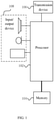
- FIG. 1 is a block diagram illustrating a hardware structure of a computer terminal performing a subframe position determination method according to an embodiment of the present disclosure.
- a computer terminal 10 may include one or more (only one is shown in FIG. 1 ) processors 102 (the processors 102 may include, but are not limited to, processing devices such as a microcontroller unit (MCU) or a field programmable gate array (FPGA)) and a memory 104 configured to store data.
- the mobile terminal may further include a transmission device 106 configured to perform communication and an input/output device 108.
- the memory 104 may be configured to store computer programs, for example, a software program and a module for application software, such as a computer program corresponding to the subframe position determination method in the embodiment of the present disclosure.
- the processor 102 executes a variety of functional applications and performs data processing by running the computer programs stored in the memory 104, that is, realizes the above-mentioned method.
- the memory 104 may include a high-speed random access memory, and may also include a non-volatile memory, such as one or more magnetic storage devices, a flash memory, or other non-volatile solid-state memory.
- the memory 104 may further include memories remotely provided from the processor 102, and these remote memories may be connected to the terminal 10 through a network. Examples of the aforementioned networks include, but are not limited to, the Internet, a corporate intranet, a local area network, a mobile communication network, and combinations thereof.
- the transmission device 106 is configured to receive or transmit data via a network.
- the example of the foregoing network may include a wireless network provided by a communication provider of the terminal 10.
- the transmission device 106 includes a network interface controller (NIC), which may be connected with other network devices through a base station so as to communicate with the Internet.
- the transmission device 106 may be a radio frequency (RF) module, and the RF module is configured to wirelessly communicate with the Internet.
- RF radio frequency
- FIG. 2 is a flowchart illustrating an optional subframe position determination method according to an embodiment of the present disclosure. As shown in FIG. 2 , the method includes the following steps:
- step S202 determining static intervals and semi-static intervals of a search space corresponding to a current subframe according to a position of the current subframe.
- step S204 determining a number of invalid subframes in the static intervals and the semi-static intervals, and determining a number of valid subframes in the static intervals and the semi-static intervals according to the number of invalid subframes.
- the static intervals and the semi-static intervals of the search space corresponding to the current subframe is determined according to the position of the current subframe.
- the number of invalid subframes in the static intervals and the semi-static intervals is determined, and the number of valid subframes in the static intervals and the semi-static intervals is determined according to the number of invalid subframes.
- the start subframe position and the end subframe position corresponding to the position of the current subframe are determined.
- the step S202 may be implemented in multiple ways.
- the maximum number of repetitions of subframe ispreconfigured and obtained.
- a position of a temporary end subframe of the current subframe is obtained by adding the maximum number of repetitions to the position of the current subframe; the static intervals and the semi-static intervals are determined according to the position of the current subframe and the position of the temporary end subframe. Determining the static intervals and the semi-static intervals according to the position of the current subframe and the position of the temporary end subframe may be performed based on a preset cycle.
- the preconfigured maximum number of repetitions of subframe is obtained.
- the position of a temporary end subframe of the current subframe is obtained by adding the maximum number of repetitions to the position of the current subframe.
- determining the number of invalid subframes in the static intervals and the semi-static intervals and determining the number of valid subframes in the static intervals and the semi-static intervals according to the number of invalid subframes may be achieved by the following technical solution in the embodiment of the present disclosure.
- a number of invalid subframes in the static intervals is determined, and a number of invalid subframes in the semi-static intervals is determined by traversing the semi-static intervals.
- the number of valid subframes in the static intervals and the semi-static intervals is determined according to the number of invalid subframes in the static intervals and the number of invalid subframes in the semi-static intervals.
- determining the number of invalid subframes in the static intervals and the semi-static intervals may also be achieved by the following technical scheme.
- a number of invalid subframes in first static intervals is determined according to a cycle of the static intervals and a type of the invalid subframes, and the number of invalid subframes in the first static intervals is taken as the number of invalid subframes in the static intervals.
- the semi-static intervals are divided into N second static intervals and M first semi-static intervals, where the M and the N are positive integers.
- a number of invalid subframes in the N second static intervals is determined according to a cycle of the N second static intervals and the type of the invalid subframes.
- a number of invalid subframes in the M first semi-static intervals is determined by traversing the semi-static intervals.
- the sequence of steps of determining the number of invalid subframes in the first static intervals, determining the number of invalid subframes in the N second static intervals and determining the number of invalid subframes in the M first semi-static intervals is not limited.
- Determining the number of valid subframes in the static intervals and the semi-static intervals according to the number of invalid subframes may be achieved by the following technical scheme.
- the number of valid subframes in the static intervals and the semi-static intervals is determined according to the number of invalid subframes in the first static intervals, the number of invalid subframes in the N second static intervals and the number of invalid subframes in the M first semi-static intervals.
- the technical scheme of the embodiment of the present disclosure mainly relates to a time-domain scheduling calculation of the NPDCCH and NPDSCH of the physical layer PHY downlink.
- a NPDCCH start time and a hybrid automatic repeat request (HARQ) feedback time it is determined to monitor positions of a start subframe and an end subframe of the NPDCCH or the NPDCCH are determined.
- HARQ hybrid automatic repeat request
- the so-called effective downlink subframes are downlink subframes except a synchronization subframe, a system information block 1 (SIB1) subframe, a system information (SI) subframe, a GAP subframe and an invalid subframe indicated by a mask bitmap).
- SIB1 system information block 1
- SI system information
- Some embodiments of the present disclosure further provide a subframe position determination apparatus, which is used to implement the above embodiments and optional implementations, and the description thereof may not be repeated if it has been described.
- the term "module” may be a combination of software and hardware that realizes a predetermined function.
- the apparatus described in the following embodiments may be implemented in software, the implementation by hardware or a combination of software and hardware is also possible and contemplated.
- FIG. 3 is a structural block diagram illustrating an optional subframe position determination apparatus according to an embodiment of the present disclosure.
- the apparatus includes a first determining module 30configured to determine static intervals and semi-static intervals of a search space corresponding to a current subframe according to a position of the current subframe; a second determining module 32configured to determine a number of invalid subframes in the static intervals and the semi-static intervals, and determine a number of valid subframes in the static intervals and the semi-static intervals according to the number of invalid subframes; and a third determining module 34 configured to determine a start subframe position and an end subframe position corresponding to the position of the current subframe according to the number of invalid subframes and the number of valid subframes.
- the static intervals and the semi-static intervals of the search space corresponding to the current subframe is determined according to the position of the current subframe.
- the number of invalid subframes in the static intervals and the semi-static intervals is determined, and the number of valid subframes in the static intervals and the semi-static intervals is determined according to the number of invalid subframes.
- the start subframe position and the end subframe position corresponding to the position of the current subframe are determined.
- the first determining module 30 is configured to obtain a preconfigured maximum number of repetitions of subframe; obtain a position of a temporary end subframe of the current subframe by adding the maximum number of repetitions to the position of the current subframe; and determine the static intervals and the semi-static intervals according to the position of the current subframe and the position of the temporary end subframe.
- the first determining module 30 is configured to determine the static intervals and the semi-static intervals according to the position of the current subframe and the position of the temporary end subframe in the following way.
- the static intervals and the semi-static intervals are determined between the position of the current subframe and the position of the end subframe according to a preset cycle.
- the second determining module 32 is configured to determine a number of invalid subframes in the static intervals and determine a number of invalid subframes in the semi-static intervals by traversing the semi-static intervals; and determine the number of valid subframes in the static intervals and the semi-static intervals according to the number of invalid subframes in the static intervals and the number of invalid subframes in the semi-static intervals.
- the second determining module 32 is configured to determine the number of invalid subframes in the static intervals and the semi-static intervals in the following way.
- a number of invalid subframes in first static intervals is determined according to a cycle of the static intervals and a type of the invalid subframes, and the number of invalid subframes in the first static intervals is taken as the number of invalid subframes in the static intervals.
- the semi-static intervals are divided into N second static intervals and M first semi-static intervals, where the M and the N are positive integers.
- a number of invalid subframes in the N second static intervals is determined according to a cycle of the N second static intervals and the type of the invalid subframes.
- a number of invalid subframes in the M first semi-static intervals is determined by traversing the first semi-static intervals.
- a space-for-time method may be used to calculate the validity of all subframes in a superframe (10240 subframes) in advance.
- a terminal side also has high requirements for space, so the space-for-time method may not be adopted.
- the calculation efficiency is greatly improved to meet the requirements of downlink processing on the terminal side.
- the first type is static (which has a fixed position), such as a subframe 0 of a physical broadcast channel (PBCH), a subframe 5 of a primary synchronization signal (PSS), and a subframe 9 of an even frame of a secondary synchronization signal (SSS).
- PBCH physical broadcast channel
- PSS primary synchronization signal
- SSS secondary synchronization signal
- the second type is semi-static (the position of which is related to configuration), such as a SIB1 subframe, a SI subframe, a GAP subframe and an invalid subframe indicated by a bitmap.
- Semi-static scenarios are also regular, that is, cyclic, and configuration parameters have a specified range.
- the embodiment of the present disclosure for both determining the end subframe position and calculating the number of valid subframes from the current subframe to the start subframe, only the number of valid subframes is required to obtain, and there is no need to accurately obtain the specific function of each subframe. Therefore, the embodiment of the present disclosure utilizes the cyclicity of invalid downlink subframes to simplify the calculation, and changes the way of traversing all intervals to a few designated semi-static intervals for calculation, while the number of invalid subframes in the static intervals can be quickly obtained. Finally, the number of traversals is reduced.
- the invalid downlink subframes herein are subframes with another characteristic, such as the SIB1 subframe.
- the occurrence times and positions of the invalid downlink subframes are fixed in a cycle. Therefore, the number of the invalid subframes may be determined, and it will not change with different configuration parameters and thus may be quickly obtained by multiplication.
- the calculation of a large interval to be may be decomposed into calculations of at most one large static interval and two small semi-static intervals.
- Each of the two semi-static intervals has one static boundary, that is, only one boundary is required to be calculated according to the configuration.
- the amount of calculation for a large interval is simplified to a single-boundary calculation for two small intervals, and other calculation for static intervals may be obtained by the most basic multiplication.
- the SIB1 is taken as an invalid subframe.
- a physical cell identity (PCID) is 0, and a repeated configuration of the SIB1 is 640 subframes; Rmax is configured as 2048 subframes.
- the current time is subframe 56, and the position of the ending subframe is calculated (i.e., counting from the current subframe to the time when the valid subframe is 2048).
- an initial value of the temporary end subframe is calculated as 2104 (2048+56) subframe first.
- the number of the SIB1 subframes in this interval is calculated, and the rest are all valid subframes.
- the position shown in FIG. 4 may be obtained by the operation of division and modulo.
- interval [56, 160] there are 8 frames in the subframe [0,160] carrying the SIB1.
- the division and modulo are performed again by taking 20 subframes as an interval.
- a simplified analysis is performed on the interval [56, 60, 160].
- [60,160] is a complete interval, and there are 5 SIB1 subframes whether it is an odd frame or an even frame.
- a remaining interval for analysis is [40, 56, 60].
- the SIB1 is fixedly carried by a 4 subframe.
- a position where the SIB1 is carried in this interval is subframe 44, so there is no SIB1 subframe in the interval [56, 60].
- the SIB1 subframes between the subframe 56 and the subframe 2104 are quickly calculated, that is, the number of invalid subframes is 21 (16+0+5+0).
- the temporary initial values established in the first round are all based on valid values, so that a second round of calculation is required.
- the number of invalid subframes obtained in the first round is added to the end position of the previous round as a new end position.
- the interval of this round is [2104, 2125 (2104+21)]. It can be seen that an interval length of the second round has been much shorter. This round of interval calculation may be performed by traversing the interval. If the interval length is still large after the second round, a quick determination similar to that of the first round continues to be used. After each round of determination, the interval required to be studied may be exponentially reduced, greatly reducing the amount of calculation.
- the algorithms for the SI subframe, the GAP subframe and the invalid subframe indicated by the bitmap are similar to that for SIB1. If these invalid subframes are configured, the determination on these invalid subframes may be made synchronously.
- the calculation efficiency can be greatly improved, and the efficiency increases as the interval for calculation becomes greater.
- the Rmax is configured to be 2048
- consumption on the instruction for calculating the end time can be reduced to 1/100, which fully meets the timing requirements for each subframe processing.
- the end subframe position can be calculated in advance while ensuring that the current processing is normal. In this way, an energy-saving mode can be entered early and the effect of power saving can be achieved.
- Some embodiments of the present disclosure further provide a computer-readable storage medium including a program stored therein.
- the program executes the method described in any one of the above.
- the storage medium may be set to store program codes for executing the following steps.
- step S1 static intervals and semi-static intervals of a search space corresponding to a current subframe is determined according to a position of the current subframe.
- step S2 a number of invalid subframes in the static intervals and the semi-static intervals is determined, and a number of valid subframes in the static intervals and the semi-static intervals is determined according to the number of invalid subframes.
- step S3 a start subframe position and an end subframe position corresponding to the position of the current subframe are determined according to the number of invalid subframes and the number of valid subframes.
- the storage medium may include but is not limited to a USB flash disk, a ROM, a RAM, a mobile hard disk, a magnetic disk or an optical disk, and other media that may store the program code.
- Some embodiments of the present disclosure further provide an electronic apparatus including a memory and a processor.
- a computer program is stored in the memory, and the processor is configured to run the computer program to execute the steps in any of the above method embodiments.
- the electronic apparatus may further include a transmission device and an input/output device, where the transmission device is connected with the processor and the input/output device is connected with the processor.
- the processor may be configured to execute the following steps through the computer program.
- step S1 static intervals and semi-static intervals of a search space corresponding to a current subframe is determined according to a position of the current subframe.
- step S2 a number of invalid subframes in the static intervals and the semi-static intervals is determined, and a number of valid subframes in the static intervals and the semi-static intervalsis determined according to the number of invalid subframes.
- step S3 a start subframe position and an end subframe position corresponding to the position of the current subframe are determined according to the number of invalid subframes and the number of valid subframes.
- a plurality of modules or steps of the present disclosure above may be realized by a general computing device, which may be concentrated on a single computing device or distributed on a network composed of a plurality of computing devices.
- the above multiple modules or steps may be realized by a program code executable by the computing device, so that they may be stored in a storage apparatus to be executed by the computing device.
- the steps shown or described may be executed in a different order from here, or they may be made into a plurality of integrated circuit modules respectively, or a plurality of modules or steps among them may be made into a single integrated circuit module. In this way, the present disclosure is not limited to any specified combination of hardware and software.
Landscapes
- Engineering & Computer Science (AREA)
- Signal Processing (AREA)
- Computer Networks & Wireless Communication (AREA)
- Mobile Radio Communication Systems (AREA)
Abstract
Description
- The present application claims priority to
Chinese patent application No. 201910937038.4, filed before China National Intellectual Property Administration on September 29, 2019 - The present disclosure relates to the field of computer technology, for example, to a subframe position determination method and apparatus, a storage medium and an electronic apparatus.
- The narrow band Internet of Things (NB-IOT) is designed to enhance the coverage by 20dB (unit of power gain) on the basis of global system for mobile communications (GSM). Taking 144dB as the maximum coupling path loss of the GSM, the maximum coupling loss (MCL) of the NB-IOT design is 164dB, and the downlink obtain coverage enhancement mainly by increasing the maximum retransmission times of each channel. In the 3rd generation partnership project (3GPP) standard, the maximum number of repetitions may be up to 2048.
- The value of the maximum number of repetitions (Rmax) in search space configuration in a narrow band (NB) may be set up to 2048, so the calculation amount required to calculate an end position based on a starting point or calculate the number of subframes between two points (starting point and current point) is quite large. It is similar when calculating the start time and end time of a narrowband physical downlink shared channel (NPDSCH). The start time of the NPDSCH is calculated based on an end subframe of a narrowband physical downlink control channel (NPDCCH) plus a configured delay time, and themaximumdelay time may be configured to be128. The maximum number of repetitions of the NPDSCH may be configured to be 2048, and the maximum number of subframes of the NPDSCH may be 10. In this way, the calculation amount required to calculate the end subframe of the NPDSCH based on a start subframe of the NPDSCH may be quite large.
- In view of the problems of large calculation amount, complex operation, etc. existing in determining the positions of the start subframe and the end subframe ofthe subframes (such as NPDCCH and NPDSCH) in the related art, no effective technical solutions has been proposed yet.
- Some embodiments of the present disclosure provide a subframe position determination method and apparatus, a storage medium, and an electronic apparatus, so as to at least solve the problems of large calculation amount, complex operation, etc. existing in determining the positions of a start subframe and an end subframe ofan subframe (such as NPDCCH and NPDSCH) in the related art.
- According to some embodiments of the present disclosure, a subframe position determination method is provided, which includes: determining static intervals and semi-static intervalsof a search space corresponding to a current subframe according to a position of the current subframe; determining a number of invalid subframes in the static intervals and the semi-static intervals, and determining a number of valid subframes in the static intervals and the semi-static intervals according to the number of invalid subframes; and determining a start subframe position and an end subframe position corresponding to the position of the current subframe according to the number of invalid subframes and the number of valid subframes.
- According to some embodiments of the present disclosure, a subframe position determination apparatus is further provided, which includes: a first determining module configured to determine static interval and semi-static intervals of a search space corresponding to a current subframe according to a position of the current subframe; a second determining module configured to determine a number of invalid subframes in the static intervals and the semi-static intervals, and determine a number of valid subframes in the static intervals and the semi-static intervals according to the number of invalid subframes; and a third determining module configured to determine a start subframe position and an end subframe position corresponding to the position of the current subframe according to the number of invalid subframes and the number of valid subframes.
- According to some embodiments of the present disclosure, a computer-readable storage medium is further provided. The storage medium includes a stored program, where the program, when running, executes the subframe position determination method described in any one of the above.
- According to some embodiments of the present disclosure, an electronic apparatus is further provided. The storage medium includes a stored program, where the program executes the subframe position determination method described in any one of the above when running on the electronic apparatus.
- The drawings described herein are used to provide an understanding of the present disclosure, which constitute a part of the present disclosure. The illustrative embodiments and descriptions of the present disclosure are used to explain the present disclosure, but do not constitute an improper limit to the present disclosure. In the accompanying drawings:
-
FIG. 1 is a block diagram illustrating a hardware structure of a computer terminal performing a subframe position determination method according to an embodiment of the present disclosure; -
FIG. 2 is a flowchart illustrating an optional subframe position determination method according to an embodiment of the present disclosure; -
FIG. 3 is a structural block diagram illustrating an optional subframe position determination apparatus according to an embodiment of the present disclosure; -
FIG. 4 is a schematic structural diagram illustrating an optional subframe position according to an embodiment of the present disclosure. - The present disclosure will be illustrated below with reference to the accompanying drawings and in combination with embodiments. The terms "first", "second", etc. in the specification and claims of the present disclosure and the above drawings are used to distinguish similar objects, but not necessarily used to describe the specified order or sequence.
- Some embodiments of the present disclosure relate to calculation of start time and end time of a NB physical downlink control channel (NPDCCH) and start time and end time of a NB physical downlink shared channel (NPDSCH) by a physical (PHY) layer in a NB-IoT coverage enhancement scenario.
- Some method embodiments provided by embodiments of the present disclosure may be executed in a computer terminal or similar computing apparatus. Taking running on the computer terminal as an example,
FIG. 1 is a block diagram illustrating a hardware structure of a computer terminal performing a subframe position determination method according to an embodiment of the present disclosure. As shown inFIG. 1 , acomputer terminal 10 may include one or more (only one is shown inFIG. 1 ) processors 102 (theprocessors 102 may include, but are not limited to, processing devices such as a microcontroller unit (MCU) or a field programmable gate array (FPGA)) and amemory 104 configured to store data. Optionally, the mobile terminal may further include atransmission device 106 configured to perform communication and an input/output device 108. Those having ordinary skill in the art may understand that the structure shown inFIG. 1 is only for illustration but does not limit the structure of the terminal. For example, themobile terminal 10 may further include more or fewer components than those shown inFIG. 1 , or have different configurations with equivalent functions or more functions than those shown inFIG. 1 . - The
memory 104 may be configured to store computer programs, for example, a software program and a module for application software, such as a computer program corresponding to the subframe position determination method in the embodiment of the present disclosure. Theprocessor 102 executes a variety of functional applications and performs data processing by running the computer programs stored in thememory 104, that is, realizes the above-mentioned method. Thememory 104 may include a high-speed random access memory, and may also include a non-volatile memory, such as one or more magnetic storage devices, a flash memory, or other non-volatile solid-state memory. In some examples, thememory 104 may further include memories remotely provided from theprocessor 102, and these remote memories may be connected to theterminal 10 through a network. Examples of the aforementioned networks include, but are not limited to, the Internet, a corporate intranet, a local area network, a mobile communication network, and combinations thereof. - The
transmission device 106 is configured to receive or transmit data via a network. The example of the foregoing network may include a wireless network provided by a communication provider of theterminal 10. In an example, thetransmission device 106 includes a network interface controller (NIC), which may be connected with other network devices through a base station so as to communicate with the Internet. In an example, thetransmission device 106 may be a radio frequency (RF) module, and the RF module is configured to wirelessly communicate with the Internet. - Some embodiments of the present disclosure provide a subframe position determination method running on the terminal shown in
FIG. 1 .FIG. 2 is a flowchart illustrating an optional subframe position determination method according to an embodiment of the present disclosure. As shown inFIG. 2 , the method includes the following steps: - at step S202, determining static intervals and semi-static intervals of a search space corresponding to a current subframe according to a position of the current subframe.
- at step S204, determining a number of invalid subframes in the static intervals and the semi-static intervals, and determining a number of valid subframes in the static intervals and the semi-static intervals according to the number of invalid subframes.
- at step S206, determining a start subframe position and an end subframe position corresponding to the position of the current subframe according to the number of invalid subframes and the number of valid subframes.
- According to the above technical scheme, the static intervals and the semi-static intervals of the search space corresponding to the current subframe is determined according to the position of the current subframe. The number of invalid subframes in the static intervals and the semi-static intervals is determined, and the number of valid subframes in the static intervals and the semi-static intervals is determined according to the number of invalid subframes. Further, the start subframe position and the end subframe position corresponding to the position of the current subframe are determined. By adopting the technical solution, the problems of large calculation amount, complex operation, etc. existing in determining the positions of the start subframe and the end subframe of the subframes (such as NPDCCH and NPDSCH) in the related art are solved. The present disclosure provides a scheme to determine the start subframe position and end subframe position of the subframe with a small amount of calculation and simple operation.
- Optionally, the step S202 may be implemented in multiple ways. In an optional implementation, the maximum number of repetitions of subframe ispreconfigured and obtained. A position of a temporary end subframe of the current subframe is obtained by adding the maximum number of repetitions to the position of the current subframe; the static intervals and the semi-static intervals are determined according to the position of the current subframe and the position of the temporary end subframe. Determining the static intervals and the semi-static intervals according to the position of the current subframe and the position of the temporary end subframe may be performed based on a preset cycle. The preconfigured maximum number of repetitions of subframe is obtained. The position of a temporary end subframe of the current subframe is obtained by adding the maximum number of repetitions to the position of the current subframe. The static intervals and the semi-static intervals are determined according to the position of the current subframe and the position of the temporary end subframe. Determining the static intervals and the semi-static intervals according to the position of the current subframe and the position of the temporarily end subframe may include determining the static intervals and the semi-static intervals between the position of the current subframe and the position of the temporary end subframe according to a preset cycle.
- After the static intervals and semi-static intervals are determined, determining the number of invalid subframes in the static intervals and the semi-static intervals and determining the number of valid subframes in the static intervals and the semi-static intervals according to the number of invalid subframes may be achieved by the following technical solution in the embodiment of the present disclosure. A number of invalid subframes in the static intervals is determined, and a number of invalid subframes in the semi-static intervals is determined by traversing the semi-static intervals. After the number of invalid subframes in the static intervals and the number of invalid subframes in the semi-static intervals are determined, the number of valid subframes in the static intervals and the semi-static intervals is determined according to the number of invalid subframes in the static intervals and the number of invalid subframes in the semi-static intervals.
- Optionally, determining the number of invalid subframes in the static intervals and the semi-static intervals may also be achieved by the following technical scheme. A number of invalid subframes in first static intervals is determined according to a cycle of the static intervals and a type of the invalid subframes, and the number of invalid subframes in the first static intervals is taken as the number of invalid subframes in the static intervals. The semi-static intervals are divided into N second static intervals and M first semi-static intervals, where the M and the N are positive integers. A number of invalid subframes in the N second static intervals is determined according to a cycle of the N second static intervals and the type of the invalid subframes. A number of invalid subframes in the M first semi-static intervals is determined by traversing the semi-static intervals.
- In the embodiment of the present disclosure, the sequence of steps of determining the number of invalid subframes in the first static intervals, determining the number of invalid subframes in the N second static intervals and determining the number of invalid subframes in the M first semi-static intervals is not limited.
- Determining the number of valid subframes in the static intervals and the semi-static intervals according to the number of invalid subframes may be achieved by the following technical scheme. The number of valid subframes in the static intervals and the semi-static intervals is determined according to the number of invalid subframes in the first static intervals, the number of invalid subframes in the N second static intervals and the number of invalid subframes in the M first semi-static intervals.
- The technical scheme of the embodiment of the present disclosure mainly relates to a time-domain scheduling calculation of the NPDCCH and NPDSCH of the physical layer PHY downlink. When calculating a NPDCCH search space, a NPDCCH start time and a hybrid automatic repeat request (HARQ) feedback time, it is determined to monitor positions of a start subframe and an end subframe of the NPDCCH or the NPDCCH are determined. In addition, it is further required to determine how many effective downlink subframes exist between the current subframe and the start subframe (the so-called effective downlink subframes are downlink subframes except a synchronization subframe, a system information block 1 (SIB1) subframe, a system information (SI) subframe, a GAP subframe and an invalid subframe indicated by a mask bitmap).
- Through the description of the above embodiments, those having ordinary skill in the art may understand that the method according to the above embodiments may be implemented by means of software plus a general hardware platform, and certainly, it may also be realized by hardware. Based on such understanding, the technical solution of the present disclosure may be embodied in the form of a software product. The computer software product is stored in a storage medium (such as a read-only memory (ROM)/ a random access memory (RAM), a magnetic disk, an optical disk) and includes a plurality of instructions to make a terminal device (which may be a mobile phone, a personal computer, a server, or a network device, etc.) to execute the method described in multiple embodiments of the present disclosure.
- Some embodiments of the present disclosure further provide a subframe position determination apparatus, which is used to implement the above embodiments and optional implementations, and the description thereof may not be repeated if it has been described. As used below, the term "module" may be a combination of software and hardware that realizes a predetermined function. Although the apparatus described in the following embodiments may be implemented in software, the implementation by hardware or a combination of software and hardware is also possible and contemplated.
-
FIG. 3 is a structural block diagram illustrating an optional subframe position determination apparatus according to an embodiment of the present disclosure. As shown inFIG. 3 , the apparatus includes a first determining module 30configured to determine static intervals and semi-static intervals of a search space corresponding to a current subframe according to a position of the current subframe; a second determining module 32configured to determine a number of invalid subframes in the static intervals and the semi-static intervals, and determine a number of valid subframes in the static intervals and the semi-static intervals according to the number of invalid subframes; and a third determiningmodule 34 configured to determine a start subframe position and an end subframe position corresponding to the position of the current subframe according to the number of invalid subframes and the number of valid subframes. - According to the above technical scheme, the static intervals and the semi-static intervals of the search space corresponding to the current subframe is determined according to the position of the current subframe. The number of invalid subframes in the static intervals and the semi-static intervals is determined, and the number of valid subframes in the static intervals and the semi-static intervals is determined according to the number of invalid subframes. Further, the start subframe position and the end subframe position corresponding to the position of the current subframe are determined. By adopting the technical solution, the problems of large calculation amount, complex operation, etc. existing in determining the positions of the start subframe and the end subframe of the subframes (such as NPDCCH and NPDSCH) in the related art are solved. The present disclosure provides a scheme to determine the start subframe position and end subframe position of the subframe with a small amount of calculation and simple operation.
- In the embodiment of the present disclosure, the first determining
module 30 is configured to obtain a preconfigured maximum number of repetitions of subframe; obtain a position of a temporary end subframe of the current subframe by adding the maximum number of repetitions to the position of the current subframe; and determine the static intervals and the semi-static intervals according to the position of the current subframe and the position of the temporary end subframe. - In the embodiment of the present disclosure, the first determining
module 30 is configured to determine the static intervals and the semi-static intervals according to the position of the current subframe and the position of the temporary end subframe in the following way. The static intervals and the semi-static intervals are determined between the position of the current subframe and the position of the end subframe according to a preset cycle. - In the embodiment of the present disclosure, the second determining
module 32 is configured to determine a number of invalid subframes in the static intervals and determine a number of invalid subframes in the semi-static intervals by traversing the semi-static intervals; and determine the number of valid subframes in the static intervals and the semi-static intervals according to the number of invalid subframes in the static intervals and the number of invalid subframes in the semi-static intervals. - In the embodiment of the present disclosure, the second determining
module 32 is configured to determine the number of invalid subframes in the static intervals and the semi-static intervals in the following way. A number of invalid subframes in first static intervals is determined according to a cycle of the static intervals and a type of the invalid subframes, and the number of invalid subframes in the first static intervals is taken as the number of invalid subframes in the static intervals. The semi-static intervals are divided into N second static intervals and M first semi-static intervals, where the M and the N are positive integers. A number of invalid subframes in the N second static intervals is determined according to a cycle of the N second static intervals and the type of the invalid subframes. A number of invalid subframes in the M first semi-static intervals is determined by traversing the first semi-static intervals. - In the embodiment of the present disclosure, the second determining
module 32 is configured to determine the number of valid subframes in the static intervals and semi-static intervals according to the number of invalid subframes in the following way. The number of valid subframes in the static intervals and the semi-static intervals is determined according to the number of invalid subframes in the first static intervals, the number of invalid subframes in the N second static intervals and the number of invalid subframes in the M first semi-static intervals. - In the embodiment of the present disclosure of the present disclosure, since NB has a repetitive function, for the computer terminal, if NPDCCH data or NPDSCH data may be obtained in advance, there is no need to continue to receive downlink data so as to save the power. Therefore, it is required to calculate the end time in advance. A conventional way for determining the valid subframes is performed subframe by subframe, so that the more subframes, the longer it takes. However, timing in the downlink processing is quite limit, and many complex processes need to be completed within 1ms, especially in a dual HARQ scheduling scenario. If the subframe-by-subframe determination method is adopted, the timing does not meet the requirements. For a base station side, a space-for-time method may be used to calculate the validity of all subframes in a superframe (10240 subframes) in advance. However, a terminal side also has high requirements for space, so the space-for-time method may not be adopted.
- Through the above technical schemes of the embodiment of the present disclosure, the calculation efficiency is greatly improved to meet the requirements of downlink processing on the terminal side.
- There are two types of so-called invalid subframes defined by a protocol. The first type is static (which has a fixed position), such as a
subframe 0 of a physical broadcast channel (PBCH), a subframe 5 of a primary synchronization signal (PSS), and a subframe 9 of an even frame of a secondary synchronization signal (SSS). - The second type is semi-static (the position of which is related to configuration), such as a SIB1 subframe, a SI subframe, a GAP subframe and an invalid subframe indicated by a bitmap.
- Semi-static scenarios are also regular, that is, cyclic, and configuration parameters have a specified range.
- In the embodiment of the present disclosure, for both determining the end subframe position and calculating the number of valid subframes from the current subframe to the start subframe, only the number of valid subframes is required to obtain, and there is no need to accurately obtain the specific function of each subframe. Therefore, the embodiment of the present disclosure utilizes the cyclicity of invalid downlink subframes to simplify the calculation, and changes the way of traversing all intervals to a few designated semi-static intervals for calculation, while the number of invalid subframes in the static intervals can be quickly obtained. Finally, the number of traversals is reduced.
- Actually, for the so-called static intervals, the number of valid downlink subframes in these intervals may be determined quickly. The invalid downlink subframes herein are subframes with another characteristic, such as the SIB1 subframe. The occurrence times and positions of the invalid downlink subframes are fixed in a cycle. Therefore, the number of the invalid subframes may be determined, and it will not change with different configuration parameters and thus may be quickly obtained by multiplication.
- In this way, the calculation of a large interval to be may be decomposed into calculations of at most one large static interval and two small semi-static intervals. Each of the two semi-static intervals has one static boundary, that is, only one boundary is required to be calculated according to the configuration. Finally, the amount of calculation for a large interval is simplified to a single-boundary calculation for two small intervals, and other calculation for static intervals may be obtained by the most basic multiplication.
- The following describes the determination process of the subframe position by way of illustration. As shown in
FIG. 4 , the SIB1 is taken as an invalid subframe. According to the current configuration, a physical cell identity (PCID) is 0, and a repeated configuration of the SIB1 is 640 subframes; Rmax is configured as 2048 subframes. The current time issubframe 56, and the position of the ending subframe is calculated (i.e., counting from the current subframe to the time when the valid subframe is 2048). - Based on the subframe56 at the current time, an initial value of the temporary end subframe is calculated as 2104 (2048+56) subframe first. In a first round, the number of the SIB1 subframes in this interval is calculated, and the rest are all valid subframes. The position shown in
FIG. 4 may be obtained by the operation of division and modulo. - There are stable cycles [640, 1280] and [1280, 1920] between the
subframe 56 and asubframe 2104 with a cycle of 640. The number of SIB1 subframes in this interval is 16 (8∗2, there are two schedules of a total of 16frames inFIG. 4 ), thus reducing1280 times for traversing, i.e. the traversing the interval [640, 1920] is avoided. The remaining intervals to be determined become [56, 640] and [1280, 2104]. - In the interval [56, 640], there is a
subframe 160 in the 640 subframe under the current SIB1 configuration. The location is different for different PCIDs. Taking PCID=0 as an example, a valid subframe range of the PCID is [0, 160], that is, the number of SIB1 subframe between [160, 640] is 0, and thus the times for traversing is reduced by 480. - In the interval [56, 160], there are 8 frames in the subframe [0,160] carrying the SIB1. The division and modulo are performed again by taking 20 subframes as an interval. A simplified analysis is performed on the interval [56, 60, 160]. [60,160] is a complete interval, and there are 5 SIB1 subframes whether it is an odd frame or an even frame.
- A remaining interval for analysis is [40, 56, 60]. The SIB1 is fixedly carried by a 4 subframe. When the PCID is 0, a position where the SIB1 is carried in this interval is subframe 44, so there is no SIB1 subframe in the interval [56, 60].
- In this way, the SIB1 subframes between the
subframe 56 and thesubframe 2104 are quickly calculated, that is, the number of invalid subframes is 21 (16+0+5+0). The temporary initial values established in the first round are all based on valid values, so that a second round of calculation is required. The number of invalid subframes obtained in the first round is added to the end position of the previous round as a new end position. The interval of this round is [2104, 2125 (2104+21)]. It can be seen that an interval length of the second round has been much shorter. This round of interval calculation may be performed by traversing the interval. If the interval length is still large after the second round, a quick determination similar to that of the first round continues to be used. After each round of determination, the interval required to be studied may be exponentially reduced, greatly reducing the amount of calculation. - The algorithms for the SI subframe, the GAP subframe and the invalid subframe indicated by the bitmap are similar to that for SIB1. If these invalid subframes are configured, the determination on these invalid subframes may be made synchronously.
- By adopting the above technical solution, the calculation efficiency can be greatly improved, and the efficiency increases as the interval for calculation becomes greater. When the Rmax is configured to be 2048, consumption on the instruction for calculating the end time can be reduced to 1/100, which fully meets the timing requirements for each subframe processing. With this method, the end subframe position can be calculated in advance while ensuring that the current processing is normal. In this way, an energy-saving mode can be entered early and the effect of power saving can be achieved.
- Some embodiments of the present disclosure further provide a computer-readable storage medium including a program stored therein. Herein, when running on the computer, the program executes the method described in any one of the above.
- Optionally, in this embodiment, the storage medium may be set to store program codes for executing the following steps. In step S1, static intervals and semi-static intervals of a search space corresponding to a current subframe is determined according to a position of the current subframe. In step S2, a number of invalid subframes in the static intervals and the semi-static intervals is determined, and a number of valid subframes in the static intervals and the semi-static intervals is determined according to the number of invalid subframes. In step S3, a start subframe position and an end subframe position corresponding to the position of the current subframe are determined according to the number of invalid subframes and the number of valid subframes.
- Optionally, in this embodiment, the storage medium may include but is not limited to a USB flash disk, a ROM, a RAM, a mobile hard disk, a magnetic disk or an optical disk, and other media that may store the program code.
- Some embodiments of the present disclosure further provide an electronic apparatus including a memory and a processor. A computer program is stored in the memory, and the processor is configured to run the computer program to execute the steps in any of the above method embodiments.
- Optionally, the electronic apparatus may further include a transmission device and an input/output device, where the transmission device is connected with the processor and the input/output device is connected with the processor.
- Optionally, in this embodiment, the processor may be configured to execute the following steps through the computer program. In step S1, static intervals and semi-static intervals of a search space corresponding to a current subframe is determined according to a position of the current subframe. In step S2, a number of invalid subframes in the static intervals and the semi-static intervals is determined, and a number of valid subframes in the static intervals and the semi-static intervalsis determined according to the number of invalid subframes. In step S3, a start subframe position and an end subframe position corresponding to the position of the current subframe are determined according to the number of invalid subframes and the number of valid subframes.
- Optionally, examples in this embodiment may refer to the examples described in the forgoing embodiments and optional implementations, which may not be repeated here.
- It should be understood by those having ordinary skill in the art that a plurality of modules or steps of the present disclosure above may be realized by a general computing device, which may be concentrated on a single computing device or distributed on a network composed of a plurality of computing devices. Alternatively, the above multiple modules or steps may be realized by a program code executable by the computing device, so that they may be stored in a storage apparatus to be executed by the computing device. In some cases, the steps shown or described may be executed in a different order from here, or they may be made into a plurality of integrated circuit modules respectively, or a plurality of modules or steps among them may be made into a single integrated circuit module. In this way, the present disclosure is not limited to any specified combination of hardware and software.
Claims (10)
- A subframe position determination method, comprising:determining static intervals and semi-static intervals of a search space corresponding to a current subframe according to a position of the current subframe;determining a number of invalid subframes in the static intervals and the semi-static intervals, and determining a number of valid subframes in the static intervals and the semi-static intervals according to the number of invalid subframes; anddetermining a start subframe position and an end subframe position corresponding to the position of the current subframe according to the number of invalid subframes and the number of valid subframes.
- The method according to claim 1, wherein determining the static intervals and the semi-static intervals of the search space corresponding to the current subframe according to the current subframe comprises:obtaining a preconfigured maximum number of repetitions of subframe;obtaining a position of a temporary end subframe of the current subframe by adding the maximum number of repetitions to the position of the current subframe; anddetermining the static intervals and the semi-static intervals according to the position of the current subframe and the position of the temporary end subframe.
- The method according to claim 2, wherein determining the static intervals and the semi-static intervals according to the position of the current subframe and the position of the temporary end subframe comprises:
determining the static intervals and the semi-static intervals between the position of the current subframe and the position of the temporary end subframe according to a preset cycle. - The method according to claim 1, wherein determining the number of invalid subframes in the static intervals and the semi-static intervals and determining the number of valid subframes in the static intervals and the semi-static intervals according to the number of invalid subframes comprises:determining a number of invalid subframes in the static intervals and determining a number of invalid subframes in the semi-static intervals by traversing the semi-static intervals; anddetermining the number of valid subframes in the static intervals and the semi-static intervals according to the number of invalid subframes in the static intervals and the number of invalid subframes in the semi-static intervals.
- The method according to claim 1, wherein determining the number of invalid subframes in the static intervals and the semi-static intervals comprises:determining a number of invalid subframes in first static intervals according to a cycle of the static intervals and a type of the invalid subframes, and taking the number of invalid subframes in the first static intervals as a number of invalid subframes in the static intervals;dividing the semi-static intervals into N second static intervals and M first semi-static intervals, wherein M and N are positive integers respectively;determining a number of invalid subframes in the N second static intervals according to a cycle of the N second static intervals and the type of the invalid subframes; anddetermining a number of invalid subframes in the M first semi-static intervals by traversing the first semi-static intervals.
- The method according to claim 5, wherein determining the number of valid subframes in the static intervals and the semi-static intervals according to the number of invalid subframes comprises:
determining the number of valid subframes in the static intervals and the semi-static intervals according to the number of invalid subframes in the first static intervals, the number of invalid subframes in the N second static intervals and the number of invalid subframes in the M first semi-static intervals. - A subframe position determination apparatus, comprising:a first determining module configured to determine static intervals and semi-static intervals of a search space corresponding to a current subframe according to a position of the current subframe;a second determining module configured to determine a number of invalid subframes in the static intervals and the semi-static intervals, and determine a number of valid subframes in the static intervals and the semi-static intervals according to the number of invalid subframes; anda third determining module configured to determine a start subframe position and an end subframe position corresponding to the position of the current subframe according to the number of invalid subframes and the number of valid subframes.
- The apparatus according to claim 7, wherein the first determining module is configured to obtain a preconfigured maximum number of repetitions of subframe; obtain a position of a temporary end subframe of the current subframe by adding the maximum number of repetitions to the position of the current subframe; and determine the static intervals and the semi-static intervals according to the position of the current subframe and the position of the temporary end subframe.
- A computer-readable storage medium storing a computer program therein, wherein, the computer program is configured to execute the method according to any one of claims 1 to 6 when running.
- An electronic apparatus comprising a memory and a processor, wherein a computer program is stored in the memory, and the processor is configured to run the computer program to execute the method according to any one of claims 1 to 6.
Applications Claiming Priority (2)
| Application Number | Priority Date | Filing Date | Title |
|---|---|---|---|
| CN201910937038.4A CN112584503B (en) | 2019-09-29 | 2019-09-29 | Method and device for determining subframe position, storage medium, and electronic device |
| PCT/CN2020/118827 WO2021058026A1 (en) | 2019-09-29 | 2020-09-29 | Subframe position determination method and apparatus, storage medium, and electronic apparatus |
Publications (3)
| Publication Number | Publication Date |
|---|---|
| EP3952545A1 true EP3952545A1 (en) | 2022-02-09 |
| EP3952545A4 EP3952545A4 (en) | 2022-08-03 |
| EP3952545B1 EP3952545B1 (en) | 2024-10-30 |
Family
ID=75110882
Family Applications (1)
| Application Number | Title | Priority Date | Filing Date |
|---|---|---|---|
| EP20869773.0A Active EP3952545B1 (en) | 2019-09-29 | 2020-09-29 | Subframe position determination method and apparatus, storage medium, and electronic apparatus |
Country Status (5)
| Country | Link |
|---|---|
| EP (1) | EP3952545B1 (en) |
| JP (1) | JP7209865B2 (en) |
| KR (1) | KR102575193B1 (en) |
| CN (1) | CN112584503B (en) |
| WO (1) | WO2021058026A1 (en) |
Family Cites Families (10)
| Publication number | Priority date | Publication date | Assignee | Title |
|---|---|---|---|---|
| CN102064877B (en) * | 2009-11-11 | 2015-01-28 | 中兴通讯股份有限公司 | Subframe scheduling information notifying method and device |
| JP6676070B2 (en) * | 2015-04-22 | 2020-04-08 | エルジー エレクトロニクス インコーポレイティド | Method for transmitting and receiving data channel and LC device |
| US10602488B2 (en) * | 2015-10-22 | 2020-03-24 | Qualocmm Incorporated | HARQ and control channel timing for enhanced machine type communications (EMTC) |
| US10321447B2 (en) * | 2015-10-26 | 2019-06-11 | Qualcomm Incorporated | Determining a DRX configuration parameter based in part on an M-PDCCH parameter |
| CN107509246B (en) * | 2016-06-14 | 2020-06-23 | 成都鼎桥通信技术有限公司 | Semi-static scheduling method and base station |
| EP3602898B1 (en) * | 2017-03-24 | 2024-02-28 | Apple Inc. | Design of early termination signal and harq-ack feedback for pusch |
| JP6882475B2 (en) * | 2017-03-24 | 2021-06-02 | エルジー エレクトロニクス インコーポレイティド | How to receive paging messages and wireless devices |
| KR20180121350A (en) * | 2017-04-28 | 2018-11-07 | 엘지전자 주식회사 | Method and wireless device for receiving paging message |
| WO2019028887A1 (en) * | 2017-08-11 | 2019-02-14 | 华为技术有限公司 | Resource allocation method and device and storage medium |
| CN109818712B (en) * | 2017-11-22 | 2021-02-19 | 大唐移动通信设备有限公司 | NPDCCH blind detection method and device based on narrowband Internet of things |
-
2019
- 2019-09-29 CN CN201910937038.4A patent/CN112584503B/en active Active
-
2020
- 2020-09-29 WO PCT/CN2020/118827 patent/WO2021058026A1/en not_active Ceased
- 2020-09-29 EP EP20869773.0A patent/EP3952545B1/en active Active
- 2020-09-29 JP JP2021561595A patent/JP7209865B2/en active Active
- 2020-09-29 KR KR1020217035271A patent/KR102575193B1/en active Active
Also Published As
| Publication number | Publication date |
|---|---|
| CN112584503A (en) | 2021-03-30 |
| JP2022531840A (en) | 2022-07-12 |
| KR20210142735A (en) | 2021-11-25 |
| EP3952545A4 (en) | 2022-08-03 |
| JP7209865B2 (en) | 2023-01-20 |
| KR102575193B1 (en) | 2023-09-06 |
| EP3952545B1 (en) | 2024-10-30 |
| WO2021058026A1 (en) | 2021-04-01 |
| CN112584503B (en) | 2024-11-15 |
Similar Documents
| Publication | Publication Date | Title |
|---|---|---|
| EP3941151B1 (en) | Reserved resource pool assisted access resource selection for small data transmission | |
| US20240397426A1 (en) | Discontinuous reception method, terminal device and network device | |
| EP3668216A1 (en) | Method for monitoring pdcch, network device, and terminal | |
| US11115955B2 (en) | Method for transmitting paging message, device, and storage medium | |
| AU2017430818B2 (en) | Discontinuous reception method, terminal device and network device | |
| US12245190B2 (en) | UE paging in NR unlicensed spectrum | |
| KR102306686B1 (en) | Wireless communication method and device | |
| AU2019265902B2 (en) | Apparatus and method for acquisition of on-demand system information in wireless communications | |
| JP7737361B2 (en) | Signal monitoring method, transmission method, terminal equipment, network equipment | |
| AU2020403028B2 (en) | Blind Detection And Descrambling Method And Device, Storage Medium, And Electronic Device | |
| US20210385785A1 (en) | Paging user equipment in new radio unlicensed spectrum | |
| WO2023138510A1 (en) | Configuration determination method and apparatus, terminal and network side device | |
| WO2017133462A1 (en) | System message update indication method, device, and system | |
| US20220256457A1 (en) | Method and device for transmitting data based on grant-free uplink scheduling, and storage medium | |
| EP4258583B1 (en) | Wireless communication method and device | |
| KR20170141792A (en) | System message acquisition determination method and terminal device | |
| CN115039478A (en) | Interval determination method and equipment | |
| EP3952545B1 (en) | Subframe position determination method and apparatus, storage medium, and electronic apparatus | |
| CN111479313A (en) | Method, terminal device and network device for paging | |
| AU2024205439A1 (en) | Apparatus and method for acquisition of periodically broadcasted system information in wireless communications | |
| WO2020133176A1 (en) | Information transmission method, terminal device and network device | |
| WO2021032049A1 (en) | Signal sending method and apparatus, signal receiving method and apparatus, first node, second node, and medium | |
| EP4415427A1 (en) | Communication method and device | |
| CN110299935A (en) | A kind of communication means, base station, terminal, storage medium, electronic device | |
| WO2025066884A1 (en) | Communication method and apparatus |
Legal Events
| Date | Code | Title | Description |
|---|---|---|---|
| STAA | Information on the status of an ep patent application or granted ep patent |
Free format text: STATUS: THE INTERNATIONAL PUBLICATION HAS BEEN MADE |
|
| PUAI | Public reference made under article 153(3) epc to a published international application that has entered the european phase |
Free format text: ORIGINAL CODE: 0009012 |
|
| STAA | Information on the status of an ep patent application or granted ep patent |
Free format text: STATUS: REQUEST FOR EXAMINATION WAS MADE |
|
| 17P | Request for examination filed |
Effective date: 20211105 |
|
| AK | Designated contracting states |
Kind code of ref document: A1 Designated state(s): AL AT BE BG CH CY CZ DE DK EE ES FI FR GB GR HR HU IE IS IT LI LT LU LV MC MK MT NL NO PL PT RO RS SE SI SK SM TR |
|
| A4 | Supplementary search report drawn up and despatched |
Effective date: 20220704 |
|
| RIC1 | Information provided on ipc code assigned before grant |
Ipc: H04L 1/18 20060101ALI20220628BHEP Ipc: H04W 72/04 20090101AFI20220628BHEP |
|
| DAV | Request for validation of the european patent (deleted) | ||
| DAX | Request for extension of the european patent (deleted) | ||
| RAP1 | Party data changed (applicant data changed or rights of an application transferred) |
Owner name: SANECHIPS TECHNOLOGY CO., LTD. |
|
| GRAP | Despatch of communication of intention to grant a patent |
Free format text: ORIGINAL CODE: EPIDOSNIGR1 |
|
| RIC1 | Information provided on ipc code assigned before grant |
Ipc: H04L 1/18 20060101ALI20240528BHEP Ipc: H04W 72/04 20090101AFI20240528BHEP |
|
| STAA | Information on the status of an ep patent application or granted ep patent |
Free format text: STATUS: GRANT OF PATENT IS INTENDED |
|
| INTG | Intention to grant announced |
Effective date: 20240704 |
|
| GRAS | Grant fee paid |
Free format text: ORIGINAL CODE: EPIDOSNIGR3 |
|
| GRAA | (expected) grant |
Free format text: ORIGINAL CODE: 0009210 |
|
| STAA | Information on the status of an ep patent application or granted ep patent |
Free format text: STATUS: THE PATENT HAS BEEN GRANTED |
|
| AK | Designated contracting states |
Kind code of ref document: B1 Designated state(s): AL AT BE BG CH CY CZ DE DK EE ES FI FR GB GR HR HU IE IS IT LI LT LU LV MC MK MT NL NO PL PT RO RS SE SI SK SM TR |
|
| REG | Reference to a national code |
Ref country code: GB Ref legal event code: FG4D |
|
| REG | Reference to a national code |
Ref country code: CH Ref legal event code: EP |
|
| REG | Reference to a national code |
Ref country code: IE Ref legal event code: FG4D |
|
| REG | Reference to a national code |
Ref country code: DE Ref legal event code: R096 Ref document number: 602020040536 Country of ref document: DE |
|
| REG | Reference to a national code |
Ref country code: LT Ref legal event code: MG9D |
|
| REG | Reference to a national code |
Ref country code: NL Ref legal event code: MP Effective date: 20241030 |
|
| PG25 | Lapsed in a contracting state [announced via postgrant information from national office to epo] |
Ref country code: PT Free format text: LAPSE BECAUSE OF FAILURE TO SUBMIT A TRANSLATION OF THE DESCRIPTION OR TO PAY THE FEE WITHIN THE PRESCRIBED TIME-LIMIT Effective date: 20250228 Ref country code: HR Free format text: LAPSE BECAUSE OF FAILURE TO SUBMIT A TRANSLATION OF THE DESCRIPTION OR TO PAY THE FEE WITHIN THE PRESCRIBED TIME-LIMIT Effective date: 20241030 Ref country code: IS Free format text: LAPSE BECAUSE OF FAILURE TO SUBMIT A TRANSLATION OF THE DESCRIPTION OR TO PAY THE FEE WITHIN THE PRESCRIBED TIME-LIMIT Effective date: 20250228 |
|
| PG25 | Lapsed in a contracting state [announced via postgrant information from national office to epo] |
Ref country code: FI Free format text: LAPSE BECAUSE OF FAILURE TO SUBMIT A TRANSLATION OF THE DESCRIPTION OR TO PAY THE FEE WITHIN THE PRESCRIBED TIME-LIMIT Effective date: 20241030 Ref country code: NL Free format text: LAPSE BECAUSE OF FAILURE TO SUBMIT A TRANSLATION OF THE DESCRIPTION OR TO PAY THE FEE WITHIN THE PRESCRIBED TIME-LIMIT Effective date: 20241030 |
|
| REG | Reference to a national code |
Ref country code: AT Ref legal event code: MK05 Ref document number: 1738180 Country of ref document: AT Kind code of ref document: T Effective date: 20241030 |
|
| PG25 | Lapsed in a contracting state [announced via postgrant information from national office to epo] |
Ref country code: BG Free format text: LAPSE BECAUSE OF FAILURE TO SUBMIT A TRANSLATION OF THE DESCRIPTION OR TO PAY THE FEE WITHIN THE PRESCRIBED TIME-LIMIT Effective date: 20241030 |
|
| PG25 | Lapsed in a contracting state [announced via postgrant information from national office to epo] |
Ref country code: ES Free format text: LAPSE BECAUSE OF FAILURE TO SUBMIT A TRANSLATION OF THE DESCRIPTION OR TO PAY THE FEE WITHIN THE PRESCRIBED TIME-LIMIT Effective date: 20241030 |
|
| PG25 | Lapsed in a contracting state [announced via postgrant information from national office to epo] |
Ref country code: NO Free format text: LAPSE BECAUSE OF FAILURE TO SUBMIT A TRANSLATION OF THE DESCRIPTION OR TO PAY THE FEE WITHIN THE PRESCRIBED TIME-LIMIT Effective date: 20250130 |
|
| PG25 | Lapsed in a contracting state [announced via postgrant information from national office to epo] |
Ref country code: AT Free format text: LAPSE BECAUSE OF FAILURE TO SUBMIT A TRANSLATION OF THE DESCRIPTION OR TO PAY THE FEE WITHIN THE PRESCRIBED TIME-LIMIT Effective date: 20241030 Ref country code: GR Free format text: LAPSE BECAUSE OF FAILURE TO SUBMIT A TRANSLATION OF THE DESCRIPTION OR TO PAY THE FEE WITHIN THE PRESCRIBED TIME-LIMIT Effective date: 20250131 Ref country code: LV Free format text: LAPSE BECAUSE OF FAILURE TO SUBMIT A TRANSLATION OF THE DESCRIPTION OR TO PAY THE FEE WITHIN THE PRESCRIBED TIME-LIMIT Effective date: 20241030 |
|
| PG25 | Lapsed in a contracting state [announced via postgrant information from national office to epo] |
Ref country code: PL Free format text: LAPSE BECAUSE OF FAILURE TO SUBMIT A TRANSLATION OF THE DESCRIPTION OR TO PAY THE FEE WITHIN THE PRESCRIBED TIME-LIMIT Effective date: 20241030 |
|
| PG25 | Lapsed in a contracting state [announced via postgrant information from national office to epo] |
Ref country code: RS Free format text: LAPSE BECAUSE OF FAILURE TO SUBMIT A TRANSLATION OF THE DESCRIPTION OR TO PAY THE FEE WITHIN THE PRESCRIBED TIME-LIMIT Effective date: 20250130 |
|
| PG25 | Lapsed in a contracting state [announced via postgrant information from national office to epo] |
Ref country code: SM Free format text: LAPSE BECAUSE OF FAILURE TO SUBMIT A TRANSLATION OF THE DESCRIPTION OR TO PAY THE FEE WITHIN THE PRESCRIBED TIME-LIMIT Effective date: 20241030 |
|
| PG25 | Lapsed in a contracting state [announced via postgrant information from national office to epo] |
Ref country code: DK Free format text: LAPSE BECAUSE OF FAILURE TO SUBMIT A TRANSLATION OF THE DESCRIPTION OR TO PAY THE FEE WITHIN THE PRESCRIBED TIME-LIMIT Effective date: 20241030 |
|
| PG25 | Lapsed in a contracting state [announced via postgrant information from national office to epo] |
Ref country code: EE Free format text: LAPSE BECAUSE OF FAILURE TO SUBMIT A TRANSLATION OF THE DESCRIPTION OR TO PAY THE FEE WITHIN THE PRESCRIBED TIME-LIMIT Effective date: 20241030 |
|
| PG25 | Lapsed in a contracting state [announced via postgrant information from national office to epo] |
Ref country code: RO Free format text: LAPSE BECAUSE OF FAILURE TO SUBMIT A TRANSLATION OF THE DESCRIPTION OR TO PAY THE FEE WITHIN THE PRESCRIBED TIME-LIMIT Effective date: 20241030 |
|
| PG25 | Lapsed in a contracting state [announced via postgrant information from national office to epo] |
Ref country code: SK Free format text: LAPSE BECAUSE OF FAILURE TO SUBMIT A TRANSLATION OF THE DESCRIPTION OR TO PAY THE FEE WITHIN THE PRESCRIBED TIME-LIMIT Effective date: 20241030 |
|
| PG25 | Lapsed in a contracting state [announced via postgrant information from national office to epo] |
Ref country code: CZ Free format text: LAPSE BECAUSE OF FAILURE TO SUBMIT A TRANSLATION OF THE DESCRIPTION OR TO PAY THE FEE WITHIN THE PRESCRIBED TIME-LIMIT Effective date: 20241030 |
|
| PG25 | Lapsed in a contracting state [announced via postgrant information from national office to epo] |
Ref country code: IT Free format text: LAPSE BECAUSE OF FAILURE TO SUBMIT A TRANSLATION OF THE DESCRIPTION OR TO PAY THE FEE WITHIN THE PRESCRIBED TIME-LIMIT Effective date: 20241030 |
|
| REG | Reference to a national code |
Ref country code: DE Ref legal event code: R097 Ref document number: 602020040536 Country of ref document: DE |
|
| PLBE | No opposition filed within time limit |
Free format text: ORIGINAL CODE: 0009261 |
|
| STAA | Information on the status of an ep patent application or granted ep patent |
Free format text: STATUS: NO OPPOSITION FILED WITHIN TIME LIMIT |
|
| PG25 | Lapsed in a contracting state [announced via postgrant information from national office to epo] |
Ref country code: SE Free format text: LAPSE BECAUSE OF FAILURE TO SUBMIT A TRANSLATION OF THE DESCRIPTION OR TO PAY THE FEE WITHIN THE PRESCRIBED TIME-LIMIT Effective date: 20241030 |
|
| 26N | No opposition filed |
Effective date: 20250731 |
|
| PGFP | Annual fee paid to national office [announced via postgrant information from national office to epo] |
Ref country code: DE Payment date: 20250805 Year of fee payment: 6 |
|
| PGFP | Annual fee paid to national office [announced via postgrant information from national office to epo] |
Ref country code: GB Payment date: 20250807 Year of fee payment: 6 |
|
| PGFP | Annual fee paid to national office [announced via postgrant information from national office to epo] |
Ref country code: FR Payment date: 20250808 Year of fee payment: 6 |
|
| REG | Reference to a national code |
Ref country code: CH Ref legal event code: H13 Free format text: ST27 STATUS EVENT CODE: U-0-0-H10-H13 (AS PROVIDED BY THE NATIONAL OFFICE) Effective date: 20260425 |