EP3952522A1 - Feedback resource determination method and apparatus for v2x service, and storage medium and terminal - Google Patents
Feedback resource determination method and apparatus for v2x service, and storage medium and terminal Download PDFInfo
- Publication number
- EP3952522A1 EP3952522A1 EP20778168.3A EP20778168A EP3952522A1 EP 3952522 A1 EP3952522 A1 EP 3952522A1 EP 20778168 A EP20778168 A EP 20778168A EP 3952522 A1 EP3952522 A1 EP 3952522A1
- Authority
- EP
- European Patent Office
- Prior art keywords
- resource
- time domain
- domain position
- slot
- candidate time
- Prior art date
- Legal status (The legal status is an assumption and is not a legal conclusion. Google has not performed a legal analysis and makes no representation as to the accuracy of the status listed.)
- Granted
Links
Images




Classifications
-
- H—ELECTRICITY
- H04—ELECTRIC COMMUNICATION TECHNIQUE
- H04L—TRANSMISSION OF DIGITAL INFORMATION, e.g. TELEGRAPHIC COMMUNICATION
- H04L1/00—Arrangements for detecting or preventing errors in the information received
- H04L1/12—Arrangements for detecting or preventing errors in the information received by using return channel
- H04L1/16—Arrangements for detecting or preventing errors in the information received by using return channel in which the return channel carries supervisory signals, e.g. repetition request signals
- H04L1/18—Automatic repetition systems, e.g. Van Duuren systems
- H04L1/1829—Arrangements specially adapted for the receiver end
- H04L1/1854—Scheduling and prioritising arrangements
-
- H—ELECTRICITY
- H04—ELECTRIC COMMUNICATION TECHNIQUE
- H04W—WIRELESS COMMUNICATION NETWORKS
- H04W72/00—Local resource management
- H04W72/02—Selection of wireless resources by user or terminal
-
- H—ELECTRICITY
- H04—ELECTRIC COMMUNICATION TECHNIQUE
- H04L—TRANSMISSION OF DIGITAL INFORMATION, e.g. TELEGRAPHIC COMMUNICATION
- H04L1/00—Arrangements for detecting or preventing errors in the information received
- H04L1/12—Arrangements for detecting or preventing errors in the information received by using return channel
- H04L1/16—Arrangements for detecting or preventing errors in the information received by using return channel in which the return channel carries supervisory signals, e.g. repetition request signals
- H04L1/1607—Details of the supervisory signal
-
- H—ELECTRICITY
- H04—ELECTRIC COMMUNICATION TECHNIQUE
- H04L—TRANSMISSION OF DIGITAL INFORMATION, e.g. TELEGRAPHIC COMMUNICATION
- H04L1/00—Arrangements for detecting or preventing errors in the information received
- H04L1/12—Arrangements for detecting or preventing errors in the information received by using return channel
- H04L1/16—Arrangements for detecting or preventing errors in the information received by using return channel in which the return channel carries supervisory signals, e.g. repetition request signals
- H04L1/18—Automatic repetition systems, e.g. Van Duuren systems
- H04L1/1812—Hybrid protocols; Hybrid automatic repeat request [HARQ]
-
- H—ELECTRICITY
- H04—ELECTRIC COMMUNICATION TECHNIQUE
- H04W—WIRELESS COMMUNICATION NETWORKS
- H04W72/00—Local resource management
- H04W72/04—Wireless resource allocation
- H04W72/044—Wireless resource allocation based on the type of the allocated resource
- H04W72/0446—Resources in time domain, e.g. slots or frames
-
- H—ELECTRICITY
- H04—ELECTRIC COMMUNICATION TECHNIQUE
- H04W—WIRELESS COMMUNICATION NETWORKS
- H04W4/00—Services specially adapted for wireless communication networks; Facilities therefor
- H04W4/30—Services specially adapted for particular environments, situations or purposes
- H04W4/40—Services specially adapted for particular environments, situations or purposes for vehicles, e.g. vehicle-to-pedestrians [V2P]
-
- H—ELECTRICITY
- H04—ELECTRIC COMMUNICATION TECHNIQUE
- H04W—WIRELESS COMMUNICATION NETWORKS
- H04W92/00—Interfaces specially adapted for wireless communication networks
- H04W92/16—Interfaces between hierarchically similar devices
- H04W92/18—Interfaces between hierarchically similar devices between terminal devices
Definitions
- the third resource is a reception resource based on the first resource being a sending resource
- the third resource is a sending resource based on the first resource being a reception resource.
- resources of the sidelink (including the first resource and the second resource) cannot multiplex downlink symbols of the Uu link.
- UE 61 and UE 62 cannot use slots 0, 1 and 5 for data transmission and HARQ feedback.
- the unavailable symbol includes the downlink symbol of the Uu link
- slot 0 of the system frame (n+1) corresponds to downlink of the Uu link
- symbols 11 to 12 of slot 0 cannot serve as a slot position of the PSFCH reception resource set.
- the determined PSFCH reception resource set includes symbols 11 to 12 of slots 4, 6 and 8, while symbols 11 to 12 of slots 9 and 0 in the PSFCH candidate reception resource set are dropped.
- FIG. 8 takes the PSSCH reception resource set as an example for description, however, in practice, those skilled in the art may use the PSCCH reception resource set as a screening standard to determine a suitable PSFCH reception resource set.
- S105 is performed, that is, the UE determines that the candidate time domain position is not the time domain position of the second resource.
- the candidate time domain positions whose corresponding slots do not contain the fourth resource may be excluded, so as to ensure the integrity of the transmission resources of the Uu link.
- the transmission resources of the Uu link multiplexed by the resources of the sidelink are prevented from being frequently interrupted.
- the first resource is a reception resource
- the second resource may be a sending resource
- the fourth resource may be a reception resource or a sending resource.
- the first resource set may be a PSSCH reception resource set
- the second resource may be a PSFCH sending resource
- the fourth resource may be a PSSCH reception resource, a PSCCH reception resource, a PSSCH sending resource or a PSCCH sending resource.
- the first resource set is the PSSCH reception resource set
- the second resource is the PSFCH sending resource
- the fourth resource is the sending resource in the PSSCH sending resource set or the PSSCH reception resource set.
- a slot structure of the Uu link in a period of 10ms is DDXUUDXXXU, where each letter represents a direction of one slot, D represents downlink, X represents flexible, and U represents uplink.
- D represents downlink
- X represents flexible
- U represents uplink.
- a direction of slot 0 is D, indicating that a data transmission direction of slot 0 is downlink, and symbols of this slot are all downlink symbols.
- a direction of slot 2 is X, indicating that a data transmission direction of slot 2 is flexible, and symbols of this slot are all flexible symbols.
- a direction of slot 3 is U, indicating that a data transmission direction of slot 3 is uplink, and symbols of this slot are all uplink symbols.
- resources of the sidelink cannot multiplex downlink symbols of the Uu link.
- UE 61 and UE 62 cannot use slots 0, 1 and 5 for data transmission and HARQ feedback.
- the base station configures feedback resources associated with the PSSCH reception resource set, and the associated feedback information indicates that a time difference between the PSSCH and the PSFCH is 2 slots.
- the time difference of 2 slots is added to slot 2 to acquire slot 4; the time difference of 2 slots is added to slot 4 to acquire slot 6; the time difference of 2 slots is added to slot 6 to acquire slot 8; the time difference of 2 slots is added to slot 7 to acquire slot 9; and the time difference of 2 slots is added to slot 8 to acquire slot 0 of a next system frame (i.e., a system frame (n+1)).
- a next system frame i.e., a system frame (n+1)
- symbols 11 to 12 of slot 4 of the system frame n symbols 11 to 12 of slot 6 of the system frame n, symbols 11 to 12 of slot 8 of the system frame n, symbols 11 to 12 of slot 9 of the system frame n, and symbol 11 to symbol 12 of slot 0 of the system frame (n+1) are the candidate time domain positions of the PSFCH sending resource in the embodiment.
- These slots may form the PSFCH candidate sending resource set in the embodiment.
- the unavailable symbol includes the downlink symbol of the Uu link
- slot 0 of the system frame (n+1) corresponds to downlink of the Uu link
- symbols 11 to 12 of slot 0 cannot serve as a slot position of the PSFCH sending resource set.
- slot 9 does not include a PSSCH sending resource or a PSSCH reception resource, symbols 11 to 12 of slot 9 cannot serve as a slot position of the PSFCH sending resource set.
- a slot structure of the Uu link in a period of 10ms is DDXUUDXXXU, where each letter represents a direction of one slot, D represents downlink, X represents flexible, and U represents uplink.
- D represents downlink
- X represents flexible
- U represents uplink.
- a direction of slot 0 is D, indicating that a data transmission direction of slot 0 is downlink, and symbols of this slot are all downlink symbols.
- a direction of slot 2 is X, indicating that a data transmission direction of slot 2 is flexible, and symbols of this slot are all flexible symbols.
- a direction of slot 3 is U, indicating that a data transmission direction of slot 3 is uplink, and symbols of this slot are all uplink symbols.
- UE 61 knows that time domain positions of its PSSCH sending resource set within 10 ms are slot 2, slot 4, and slots 6 to 8 through configuration of the base station. In addition, each PSSCH sending resource merely occupies symbol 3 to symbol 11 of the corresponding slot.
- the PSFCH reception resource in the PSFCH reception resource set may be determined to be located at symbol 11 to symbol 12 of a slot by configuration or pre-configuration.
- the PSFCH candidate reception resources that do not meet requirements can be excluded from symbols 11 to 12 of slots 4, 6, 8 and 9 based on the PSSCH reception resource set and the PSSCH sending resource set.
- slot 6 and slot 8 include both PSSCH reception resources and PSSCH sending resources, symbols 11 to 12 of slots 4 and 6 can serve as slot positions of the PSFCH reception resource set.
- slot 9 does not include a PSSCH reception resource or a PSSCH sending resource, symbols 11 to 12 of slot 9 cannot serve as a slot position of the PSFCH reception resource set.
- FIG. 11 takes the PSSCH reception resource set and the PSSCH sending resource set as an example for description, however, in practice, those skilled in the art may use the PSCCH reception resource set and the PSSCH sending resource set as a screening standard to determine a suitable PSFCH reception resource set.
- solutions provided in the embodiments as shown in FIG. 1 to FIG. 11 may be used to determine a time domain position of the feedback reception resource, and a frequency domain position of the feedback reception resource may be determined using other technologies. Further, feedback information corresponding to sidelink data sent is received on the determined time and frequency domain positions of the feedback reception resource.
- the symbols occupied by each candidate time domain position are available symbols. Accordingly, after S102 is performed to determine the candidate time domain position of the second resource, the determined candidate time domain position may be directly determined as the time domain position of the second resource.
- FIG. 12 is a structural diagram of a feedback resource determination apparatus for V2X service according to an embodiment.
- the feedback resource determination apparatus 3 for V2X service provided in the embodiment may be used to implement the method provided in the embodiments as shown in FIGS. 1 to 11 .
- the fourth resource is a reception resource or a sending resource based on the first resource being a sending resource
- the fourth resource is a reception resource or a sending resource based on the first resource being a reception resource
- the first judging circuitry 33 is called to perform corresponding operations based on the second judging circuitry 35 determining that the UE is within the network coverage.
- a storage medium having computer instructions stored therein is provided, wherein when the computer instructions are executed, the above method as shown in FIGS. 1 to 11 is performed.
- the storage medium may include a computer readable storage medium, such as a non-volatile memory or a non-transitory memory.
- the computer readable storage medium may include a Read Only Memory (ROM), a Random Access Memory (RAM), a magnetic disk or an optical disk.
- a terminal including a memory and a processor
- the memory has computer instructions stored therein, and when the processor executes the computer instructions, the above method as shown in FIGS. 1 to 11 is performed.
- the terminal may be a UE applied in an NR V2X scenario.
Landscapes
- Engineering & Computer Science (AREA)
- Computer Networks & Wireless Communication (AREA)
- Signal Processing (AREA)
- Mobile Radio Communication Systems (AREA)
Abstract
Description
- This application claims the priority to
Chinese Application No. 201910243661.X, filed on March 28, 2019 - The present disclosure generally relates to communication technology field, and more particularly, to a feedback resource determination method and apparatus for vehicle-to-everything (V2X) service, a storage medium and a terminal.
- With the development of the 3rd Generation Partnership Project (3GPP), New Radio (NR) V2X as a key technical direction of Release 16 (R16) of a standard is being studied. NR V2X, as an enhancement of Long Term Evolution (LTE) V2X, is a key technical means to enable the Internet of Vehicles.
- To meet various service needs of the Internet of Vehicles, NR V2X supports three data transmission modes including unicast, multicast and broadcast. To improve reliability of unicast and multicast communication, 3GPP has reached an agreement through discussion to introduce a feedback mechanism in unicast and multicast, such as Hybrid Automatic Repeat reQuest (HARQ) feedback mechanism. HARQ feedback content is included in Sidelink Feedback Control Information (SFCI) for transmission, and the SFCI is carried by a Physical Sidelink Feedback Channel (PSFCH, also referred to as Sidelink Feedback Channel).
- The latest standard further determines that a time difference between a Physical Sidelink Shared Channel (PSSCH, also referred to as Sidelink Shared Channel) and its associated PSFCH can be acquired by network configuration or pre-configuration.
- In LTE V2X, resource pools are configured for PSSCH and Physical Sidelink Control Channel (PSCCH, also referred to as Sidelink Control Channel) through network configuration or pre-configuration. The resource pools include multiple resources. In practice, User Equipment (UE) can transmit data or control signaling on one or more resources in a transmission resource pool, and receive data or control signaling on one or more resources in a reception resource pool.
- However, as LTE V2X does not support a feedback mechanism, there is no PSFCH. Therefore, there is no solution on how a UE acquires resources for PSFCH, which causes the UE in an NR V2X scenario to be unable to acquire the resources for PSFCH from resource pools configured by the network or pre-configured.
- By embodiments of the present disclosure, a UE in an NR V2X scenario may efficiently and accurately determine resources for PSFCH.
- In an embodiment of the present disclosure, a feedback resource determination method for V2X service is provided, including: acquiring a first resource set, wherein the first resource set includes a time domain position of at least one first resource which is a transmission resource for a PSSCH; for each of the at least one first resource, determining a candidate time domain position of a second resource corresponding to the first resource based on the time domain position of the first resource and associated feedback information, wherein the second resource is a transmission resource for a PSFCH, and the associated feedback information indicates a time difference between the PSSCH and the PSFCH; for each candidate time domain position, determining whether symbols occupied by the candidate time domain position include an unavailable symbol, wherein the unavailable symbol is a symbol that cannot be used to transmit the second resource; and determining the candidate time domain position as a time domain position of the second resource based on the symbols occupied by the candidate time domain position not including the unavailable symbol.
- Optionally, said determining the candidate time domain position as a time domain position of the second resource based on the symbols occupied by the candidate time domain position not including the unavailable symbol includes: determining whether a slot where the candidate time domain position is located includes a third resource based on the symbols occupied by the candidate time domain position not including the unavailable symbol, wherein the third resource is a transmission resource for the PSSCH or the PSCCH, and a data transmission direction of the third resource is different from a data transmission direction of the first resource; and determining the candidate time domain position as the time domain position of the second resource based on the slot where the candidate time domain position is located including the third resource.
- Optionally, the third resource is a reception resource based on the first resource being a sending resource, and the third resource is a sending resource based on the first resource being a reception resource.
- Optionally, said determining the candidate time domain position as a time domain position of the second resource based on the symbols occupied by the candidate time domain position not including the unavailable symbol includes: determining whether a slot where the candidate time domain position is located includes a fourth resource based on the symbols occupied by the candidate time domain position not including the unavailable symbol, wherein the fourth resource is a transmission resource for the PSSCH or the PSCCH, and a data transmission direction of the fourth resource is the same as or different from a data transmission direction of the first resource; and determining the candidate time domain position as the time domain position of the second resource based on the slot where the candidate time domain position is located including the fourth resource.
- Optionally, the fourth resource is a reception resource or a sending resource based on the first resource being a sending resource, and the fourth resource is a reception resource or a sending resource based on the first resource being a reception resource.
- Optionally, said determining a candidate time domain position of a second resource corresponding to the first resource based on the time domain position of the first resource and associated feedback information includes: determining a candidate slot where the second resource is located based on a slot where a termination position of the first resource is located and the associated feedback information; and determining the candidate time domain position of the second resource in the candidate slot based on configured or pre-configured position information of the second resource in the candidate slot.
- Optionally, the second resource is a reception resource based on the first resource being a sending resource, and the second resource is a sending resource based on the first resource being a reception resource.
- Optionally, the first resource set is acquired by configuration or pre-configuration, the associated feedback information is determined by configuration or pre-configuration, and the first resource set has a one-to-one correspondence with the associated feedback information.
- Optionally, the first resource and the second resource are resources of a sidelink and multiplex a transmission resource of a Uu link, and the unavailable symbol includes a downlink symbol of the Uu link.
- Optionally, the unavailable symbol further includes a flexible symbol of the Uu link.
- Optionally, the method further includes: prior to determining whether symbols occupied by the candidate time domain position include an unavailable symbol, determining whether a UE is within a network coverage; and determining each candidate time domain position as the time domain position of the second resource based on the UE being beyond the network coverage.
- In an embodiment of the present disclosure, a feedback resource determination apparatus for V2X service is provided, including: an acquiring circuitry configured to acquire a first resource set, wherein the first resource set includes a time domain position of at least one first resource which is a transmission resource for a PSSCH; a first determining circuitry configured to: for each of the at least one first resource, determine a candidate time domain position of a second resource corresponding to the first resource based on the time domain position of the first resource and associated feedback information, wherein the second resource is a transmission resource for a PSFCH, and the associated feedback information indicates a time difference between the PSSCH and the PSFCH; a first judging circuitry configured to: for each candidate time domain position, determine whether symbols occupied by the candidate time domain position include an unavailable symbol, wherein the unavailable symbol is a symbol that cannot be used to transmit the second resource; and a second determining circuitry configured to determine the candidate time domain position as a time domain position of the second resource based on the symbols occupied by the candidate time domain position not including the unavailable symbol.
- In an embodiment of the present disclosure, a storage medium having computer instructions stored therein is provided, wherein when the computer instructions are executed, the above method is performed.
- In an embodiment of the present disclosure, a terminal including a memory and a processor is provided, wherein the memory has computer instructions stored therein, and when the processor executes the computer instructions, the above method is performed.
- Embodiments of the present disclosure may provide following advantages.
- Embodiments of the present disclosure provide a feedback resource determination method for V2X service. The method includes: acquiring a first resource set, wherein the first resource set includes a time domain position of at least one first resource which is a transmission resource for a PSSCH; for each of the at least one first resource, determining a candidate time domain position of a second resource corresponding to the first resource based on the time domain position of the first resource and associated feedback information, wherein the second resource is a transmission resource for a PSFCH, and the associated feedback information indicates a time difference between the PSSCH and the PSFCH; for each candidate time domain position, determining whether symbols occupied by the candidate time domain position include an unavailable symbol, wherein the unavailable symbol is a symbol that cannot be used to transmit the second resource; and determining the candidate time domain position as a time domain position of the second resource based on the symbols occupied by the candidate time domain position not including the unavailable symbol. By embodiments of the present disclosure, a UE in an NR V2X scenario may efficiently and accurately determine resources for PSFCH without extra signaling configuration, thereby reducing signaling overhead. The time difference between the PSSCH and the PSFCH is determined based on the associated feedback information, and for each first resource, the time domain position of the first resource is added to the time difference to acquire the candidate time domain position of the corresponding second resource. Further, whether the candidate time domain position can be used as the time domain position of the second resource is determined based on the symbols occupied by the candidate time domain position, so as to exclude the candidate time domain that contains an unavailable symbol.
- Further, whether a slot where the candidate time domain position is located includes a fourth resource is determined based on the symbols occupied by the candidate time domain position not including the unavailable symbol, wherein the fourth resource is a transmission resource for the PSSCH or the PSCCH, and a data transmission direction of the fourth resource is the same as or different from a data transmission direction of the first resource; and the candidate time domain position is determined as the time domain position of the second resource based on the slot where the candidate time domain position is located including the fourth resource. Therefore, integrity of transmission resources of the Uu link and resource utilization may be improved. Specifically, by the determination step, the candidate time domain positions whose corresponding slots do not contain the fourth resource may be excluded, so as to ensure the integrity of the transmission resources of the Uu link. In other words, by using the candidate time domain position in the slot that contains the fourth resource as the time domain position of the second resource, the transmission resources of the Uu link multiplexed by the resources of the sidelink (especially the transmission resource of the Uu link that does not include the fourth resource) are prevented from being frequently interrupted.
- Further, whether a slot where the candidate time domain position is located includes a third resource is determined based on the symbols occupied by the candidate time domain position not including the unavailable symbol, wherein the third resource is a transmission resource for the PSSCH or the PSCCH, and a data transmission direction of the third resource is different from a data transmission direction of the first resource; and the candidate time domain position is determined as the time domain position of the second resource based on the slot where the candidate time domain position is located including the third resource. Therefore, integrity of transmission resources of the Uu link may be improved, and complexity of the UE may be reduced. Specifically, by the determination step, the candidate time domain positions whose corresponding slots do not contain the fourth resource may be excluded, so as to ensure the integrity of the transmission resources of the Uu link. In other words, by using the candidate time domain position in the slot that contains the third resource as the time domain position of the second resource, the transmission resources of the Uu link multiplexed by the resources of the sidelink (especially the transmission resource of the Uu link that does not include the third resource) are prevented from being frequently interrupted. Further, the data transmission direction of the third resource is the same as the data transmission direction of the first resource, that is, the data transmission direction of the third resource is different from the data transmission direction of the second resource. Therefore, the UE transmits data in the same direction in the slot, and does not need to frequently switch between receiving and transmitting operations in a single slot, which makes it possible to reduce the complexity of the UE.
-
-
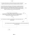
FIG. 1 is a flow chart of a feedback resource determination method for V2X service according to an embodiment; -
FIG. 2 is a flow chart of S102 as shown inFIG. 1 according to an embodiment; -
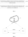
FIG. 3 is a communication diagram of an application scenario according to an embodiment; -
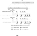
FIG. 4 is a diagram of a feedback resource determining process where the method as shown inFIG. 1 is applied to the scenario as shown inFIG. 3 according to an embodiment; -
FIG. 5 is a diagram of a feedback resource determining process where the method as shown inFIG. 1 is applied to the scenario as shown inFIG. 3 according to another embodiment; -
FIG. 6 is a flow chart of a feedback resource determination method for V2X service according to an embodiment; -
FIG. 7 is a diagram of a feedback resource determining process where the method as shown inFIG. 6 is applied to the scenario as shown inFIG. 3 according to an embodiment; -
FIG. 8 is a diagram of a feedback resource determining process where the method as shown inFIG. 6 is applied to the scenario as shown inFIG. 3 according to another embodiment; -
FIG. 9 is a flow chart of a feedback resource determination method for V2X service according to an embodiment; -
FIG. 10 is a diagram of a feedback resource determining process where the method as shown inFIG. 9 is applied to the scenario as shown inFIG. 3 according to an embodiment; -
FIG. 11 is a diagram of a feedback resource determining process where the method as shown inFIG. 9 is applied to the scenario as shown inFIG. 3 according to another embodiment; and -
FIG. 12 is a structural diagram of a feedback resource determination apparatus for V2X service according to an embodiment. - As described in the background, sidelink feedback mechanisms in NR V2X scenarios are imperfect, thus the UE in NR V2X scenarios is unable to acquire the resources for PSFCH from resource pools configured by the network or pre-configured.
- In an embodiment of the present disclosure, a feedback resource determination method for V2X service is provided, including: acquiring a first resource set, wherein the first resource set includes a time domain position of at least one first resource which is a transmission resource for a PSSCH; for each of the at least one first resource, determining a candidate time domain position of a second resource corresponding to the first resource based on the time domain position of the first resource and associated feedback information, wherein the second resource is a transmission resource for a PSFCH, and the associated feedback information indicates a time difference between the PSSCH and the PSFCH; for each candidate time domain position, determining whether symbols occupied by the candidate time domain position include an unavailable symbol, wherein the unavailable symbol is a symbol that cannot be used to transmit the second resource; and determining the candidate time domain position as a time domain position of the second resource based on the symbols occupied by the candidate time domain position not including the unavailable symbol.
- By embodiments of the present disclosure, a UE in an NR V2X scenario may efficiently and accurately determine resources for PSFCH without extra signaling configuration, thereby reducing signaling overhead.
- The time difference between the PSSCH and the PSFCH is determined based on the associated feedback information, and for each first resource, the time domain position of the first resource is added to the time difference to acquire the candidate time domain position of the corresponding second resource.
- Further, whether the candidate time domain position can be used as the time domain position of the second resource is determined based on the symbols occupied by the candidate time domain position, so as to exclude the candidate time domain that contains an unavailable symbol.
- In order to clarify the objects, characteristics and advantages of the disclosure, embodiments of present disclosure will be described in detail in conjunction with accompanying drawings.
-
FIG. 1 is a flow chart of a feedback resource determination method for V2X service according to an embodiment. The embodiment may be applied to Internet of Vehicles, such as an NR V2X scenario. The embodiment may be performed by a UE side, for example, by a UE as a sender and/or a receiver. The UE may perform HARQ feedback in a unicast or multicast mode using a feedback resource determined by solutions of the embodiment. - Referring to
FIG. 1 , the method may include S101 to S105. - In S101, a UE acquires a first resource set, wherein the first resource set includes a time domain position of at least one first resource which is a transmission resource for a PSSCH.
- In S102, for each of the at least one first resource, the UE determines a candidate time domain position of a second resource corresponding to the first resource based on the time domain position of the first resource and associated feedback information, wherein the second resource is a transmission resource for a PSFCH, and the associated feedback information indicates a time difference between the PSSCH and the PSFCH.
- In S103, for each candidate time domain position, the UE determines whether symbols occupied by the candidate time domain position include an unavailable symbol, wherein the unavailable symbol is a symbol that cannot be used to transmit the second resource.
- In S104, the UE determines the candidate time domain position as a time domain position of the second resource based on the symbols occupied by the candidate time domain position not including the unavailable symbol.
- In S105, the UE determines that the candidate time domain position is not the time domain position of the second resource based on the symbols occupied by the candidate time domain position including the unavailable symbol.
- In some embodiments, the first resource and the second resource are both resources of a sidelink, and the resources of the sidelink multiplex resources allocated by the base station to the UE for data transmission through a Uu interface (also referred to as transmission resources of a Uu link).
- For example, the base station may allocate resource pools for the UE in a configuration or pre-configuration manner, and the resource pools may be shared by the Uu link and the sidelink, where the resource pools may include a sending resource pool and a reception resource pool.
- Further, the first resource set may be acquired by configuration or pre-configuration. The first resource set may indicate time domain positions of first resources in the resource pools.
- For example, the first resource set may be indicated by downlink signaling (such as RRC signaling) transmitted in advance by the base station.
- For another example, the first resource set may be preconfigured in a Subscriber Identification Module (SIM card) associated with the UE.
- Further, the unavailable symbol may refer to a symbol occupied by a transmission resource of the Uu link that cannot be multiplexed by a sidelink.
- For example, the unavailable symbol may include a downlink symbol of the Uu link. Accordingly, in S103, if the symbols occupied by the candidate time domain position are all non-downlink symbols of the Uu link, it may be determined that the candidate time domain position is the time domain position of the second resource. The non-downlink symbols may include uplink symbols and flexible symbols. A data transmission direction on the flexible symbols can be adjusted based on configuration or a manner dynamical indicated by the base station.
- For another example, the unavailable symbol may include downlink symbols and flexible symbols of the Uu link. Accordingly, in S103, if the symbols occupied by the candidate time domain position are all uplink symbols of the Uu link, it may be determined that the candidate time domain position is the time domain position of the second resource.
- Further, the uplink symbols and the non-downlink symbols correspond to semi-static uplink and downlink slot structure configuration of the NR Uu link, including cell-specific semi-static DL/UL assignment and UE-specific semi-static DL/UL assignment.
- Further, based on provisions of standards, in the scenario where the Uu link and the sidelink share resources, the sidelink may not multiplex the downlink symbols of the Uu link. Therefore, the unavailable symbol may be a symbol that cannot be used to transmit the first resource.
- In some embodiments, the associated feedback information may include configured or pre-configured information about a time difference between the PSSCH and the PSFCH. For example, if a bit value of the associated feedback information is non-zero, the bit value is the time difference between the PSSCH and PSFCH. For another example, if the bit value of the associated feedback information is zero, it indicates that the base station has not configured a corresponding feedback resource for the UE.
- In some embodiments, the associated feedback information may include indication information on whether there is a corresponding feedback resource, and a time difference between the PSSCH and the PSFCH when the indication information indicates that there is a corresponding feedback resource. For example, the associated feedback information may include 3 bits, where the first bit indicates whether there is a corresponding feedback resource, and 0 means no and 1 means yes. Further, when the first bit is 1, the following two bits indicate the time difference between the PSSCH and the PSFCH. In some embodiments, 00 indicates that the time difference is 1 slot, 01 indicates that the time difference is 2 slots, 10 indicates that the time difference is 3 slots, and 11 indicates that the time difference is 4 slots.
- In practice, those skilled in the art can adjust a number of bits included in the associated feedback information and meaning of each bit according to practical requirements.
- Further, the associated feedback information may be determined by configuration or pre-configuration.
- Further, the first resource set may have a one-to-one correspondence with the associated feedback information. For different first resource sets, different associated feedback information may be configured or pre-configured. For example, the time difference included in the associated feedback information corresponding to first resource set 1 may be 1 slot, and the time difference included in the associated feedback information corresponding to first resource set 2 may be 2 slots.
- In some embodiments, the second resource may be a reception resource based on the first resource being a sending resource. For example, the first resource set may be a PSSCH sending resource set, and the second resource may be a PSFCH reception resource.
- In some embodiments, the second resource may be a sending resource based on the first resource being a reception resource. For example, the first resource set may be a PSSCH reception resource set, and the second resource may be a PSCCH sending resource.
- In some embodiments, referring to
FIG. 2 , S102 may include S1021 and S1022. - In S1021, the UE determines a candidate slot where the second resource is located based on a slot where a termination position of the first resource is located and the associated feedback information.
- In S1022, the UE determines the candidate time domain position of the second resource in the candidate slot based on configured or pre-configured position information of the second resource in the candidate slot.
- In some embodiments, the termination position of the first resource may be a position of a last symbol occupied by the first resource on the slot.
- In some embodiments, the time difference between the PSSCH and the PSFCH indicated in the associated feedback information may be a slot difference.
- Further, in S1021, a slot where the last symbol occupied by the first resource is located may be determined, and the slot is added to the slot difference indicated by the associated feedback information to acquire the candidate slot.
- Further, in S1022, it is assumed that the last symbol of the first resource is located in slot 5, the slot difference is 3 slots, and the second resource indicated by configuration or pre-configuration is located within
symbol 12 to symbol 13 in a slot, it is determined that the second resource is located insymbol 12 to symbol 13 ofslot 8. - Referring to
FIG. 3 , in an application scenario,UE 61 andUE 62 perform unicast communication.UE 61 transmits unicast data toUE 62, and after receiving unicast data fromUE 61,UE 62 transmits HARQ feedback information based on a decoding result of the unicast data. The unicast data is carried by a PSSCH, and the HARQ feedback information is carried by a PSFCH. - Further, both the unicast data communication and the HARQ feedback communication between
UE 61 andUE 62 use resources of a sidelink for transmission. The resources of the sidelink share transmission resources of the Uu link. Therefore, to determine the transmission resources available for the PSFCH,UE 62 and theUE 61 need to determine feedback resources for PSSCH transmission allocated bybase station 63. Thebase station 63 is used to maintain network communication ofcell 1. - In the below embodiment, the first resource set is a PSSCH reception resource set and the second resource is a PSFCH sending resource.
-
FIG. 4 exemplarily illustrates a time domain position of a transmission resource of the Uu link allocated bybase station 63 in a slot of 20 milliseconds (ms). The transmission resource of the Uu link repeats in a time domain with a period of 10 ms. - As shown in
FIG. 4 , taking a system frame n as an example, assume that a slot structure of the Uu link in a period of 10ms is DDXUUDXXXU, where each letter represents a direction of one slot, D represents downlink, X represents flexible, and U represents uplink. For example, a direction ofslot 0 is D, indicating that a data transmission direction ofslot 0 is downlink, and symbols of this slot are all downlink symbols. A direction ofslot 2 is X, indicating that a data transmission direction ofslot 2 is flexible, and symbols of this slot are all flexible symbols. A direction ofslot 3 is U, indicating that a data transmission direction ofslot 3 is uplink, and symbols of this slot are all uplink symbols. - Based on provisions of standards, resources of the sidelink (including the first resource and the second resource) cannot multiplex downlink symbols of the Uu link. In the example as shown in
FIG. 4 , during unicast communication betweenUE 61 andUE 62,UE 61 andUE 62 cannot useslots - Continuing to refer to
FIG. 4 , it is assumed thatUE 62 knows that time domain positions of its PSSCH reception resource set within 10 ms areslot 2,slot 4, andslots 6 to 8 through configuration of the base station. In addition, each PSSCH reception resource merely occupiessymbol 3 tosymbol 11 of the corresponding slot. - Further, the base station configures feedback resources associated with the PSSCH reception resource set, and the associated feedback information indicates that a time difference between the PSSCH and the PSFCH is 2 slots.
- Therefore, when
UE 62 receives data in the configured PSSCH reception resource set and needs to send a feedback, according to the feedback resource determination method as shown inFIG. 1 andFIG. 2 ,UE 62 may add the time difference to a slot where a termination position of each reception resource in the PSSCH reception resource set is located so as to acquire a candidate slot. Specifically, in the example as shown inFIG. 4 , the time difference of 2 slots is added toslot 2 to acquireslot 4; the time difference of 2 slots is added toslot 4 to acquireslot 6; the time difference of 2 slots is added toslot 6 to acquireslot 8; the time difference of 2 slots is added toslot 7 to acquireslot 9; and the time difference of 2 slots is added toslot 8 to acquireslot 0 of a next system frame (i.e., a system frame (n+1)). - Further, the PSFCH sending resource in the PSFCH sending resource set may be determined to be located at
symbol 11 tosymbol 12 of a slot by configuration or pre-configuration. - Therefore, it is determined that
symbols 11 to 12 ofslot 4 of the system frame n,symbols 11 to 12 ofslot 6 of the system frame n,symbols 11 to 12 ofslot 8 of the system frame n,symbols 11 to 12 ofslot 9 of the system frame n, andsymbol 11 tosymbol 12 ofslot 0 of the system frame (n+1) are the candidate time domain positions of the PSFCH sending resource in the embodiment. These slots may form the PSFCH candidate sending resource set in the embodiment. - When the unavailable symbol includes the downlink symbol of the Uu link, as
slot 4 andslot 9 of the system frame n correspond to uplink rather than downlink of the Uu link,symbols 11 to 12 ofslot 4 andslot 9 can serve as a slot position of the PSFCH sending resource set. Asslot 6 andslot 8 of the system frame n correspond to flexible rather than downlink of the Uu link,symbols 11 to 12 ofslot 6 andslot 8 can serve as a slot position of the PSFCH sending resource set. Asslot 0 of the system frame (n+1) corresponds to downlink of the Uu link,symbols 11 to 12 ofslot 0 cannot serve as a slot position of the PSFCH sending resource set. - Therefore, in the embodiment as shown in
FIG. 4 , the determined PSFCH sending resource set includessymbols 11 to 12 ofslots symbols 11 to 12 ofslot 0 in the PSFCH candidate sending resource set are dropped. - When the unavailable symbol includes the downlink symbols and flexible symbols of the Uu link, as merely
slot 4 andslot 9 correspond to uplink rather than downlink or flexible of the Uu link, the determined PSFCH sending resource set includessymbols 11 to 12 ofslots symbols 11 to 12 ofslots - In the below embodiment, the first resource set is a PSSCH sending resource set and the second resource is a PSFCH reception resource.
-
FIG. 5 exemplarily illustrates a time domain position of a transmission resource of the Uu link allocated bybase station 63 in a slot of 20 milliseconds (ms). The transmission resource of the Uu link repeats in the time domain with a period of 10 ms. - As shown in
FIG. 5 , taking a system frame n as an example, assume that a slot structure of the Uu link in a period of 10ms is DDXUUDXXXU, where each letter represents a direction of one slot, D represents downlink, X represents flexible, and U represents uplink. For example, a direction ofslot 0 is D, indicating that a data transmission direction ofslot 0 is downlink, and symbols of this slot are all downlink symbols. A direction ofslot 2 is X, indicating that a data transmission direction ofslot 2 is flexible, and symbols of this slot are all flexible symbols. A direction ofslot 3 is U, indicating that a data transmission direction ofslot 3 is uplink, and symbols of this slot are all uplink symbols. - Based on provisions of standards, resources of the sidelink (including the first resource and the second resource) cannot multiplex downlink symbols of the Uu link. In the example as shown in
FIG. 5 , during unicast communication betweenUE 61 andUE 62,UE 61 andUE 62 cannot useslots - Continuing to refer to
FIG. 5 , it is assumed thatUE 61 knows that time domain positions of its PSSCH sending resource set within 10 ms areslot 2,slot 4, andslots 6 to 8 through configuration of the base station. In addition, each PSSCH sending resource merely occupiessymbol 3 tosymbol 11 of the corresponding slot. - Further, the base station configures feedback resources associated with the PSSCH sending resource set, and the associated feedback information indicates that a time difference between the PSSCH and the PSFCH is 2 slots.
- Therefore, when
UE 61 transmits data in the configured PSSCH sending resource set and needs to receive a feedback, according to the feedback resource determination method as shown inFIG. 1 andFIG. 2 ,UE 61 may add the time difference to a slot where a termination position of each sending resource in the PSSCH sending resource set is located so as to acquire a candidate slot. Specifically, in the example as shown inFIG. 5 , the time difference of 2 slots is added toslot 2 to acquireslot 4; the time difference of 2 slots is added toslot 4 to acquireslot 6; the time difference of 2 slots is added toslot 6 to acquireslot 8; the time difference of 2 slots is added toslot 7 to acquireslot 9; and the time difference of 2 slots is added toslot 8 to acquireslot 0 of a next system frame (i.e., a system frame (n+1)). - Further, the PSFCH reception resource in the PSFCH reception resource set may be determined to be located at
symbol 11 tosymbol 12 of a slot by configuration or pre-configuration. - Therefore, it is determined that
symbols 11 to 12 ofslot 4 of the system frame n,symbols 11 to 12 ofslot 6 of the system frame n,symbols 11 to 12 ofslot 8 of the system frame n,symbols 11 to 12 ofslot 9 of the system frame n, andsymbol 11 tosymbol 12 ofslot 0 of the system frame (n+1) are the candidate time domain positions of the PSFCH reception resource in the embodiment. These slots may form the PSFCH candidate reception resource set in the embodiment. - When the unavailable symbol includes the downlink symbol of the Uu link, as
slot 4 andslot 9 of the system frame n correspond to uplink rather than downlink of the Uu link,symbols 11 to 12 ofslot 4 andslot 9 can serve as a slot position of the PSFCH reception resource set. Asslot 6 andslot 8 of the system frame n correspond to flexible rather than downlink of the Uu link,symbols 11 to 12 ofslot 6 andslot 8 can serve as a slot position of the PSFCH reception resource set. Asslot 0 of the system frame (n+1) corresponds to downlink of the Uu link,symbols 11 to 12 ofslot 0 cannot serve as a slot position of the PSFCH reception resource set. - Therefore, in the embodiment as shown in
FIG. 5 , the determined PSFCH reception resource set includessymbols 11 to 12 ofslots symbols 11 to 12 ofslot 0 in the PSFCH candidate reception resource set are dropped. - When the unavailable symbol includes the downlink symbols and flexible symbols of the Uu link, as merely
slot 4 andslot 9 correspond to uplink rather than downlink or flexible of the Uu link, the determined PSFCH reception resource set includessymbols 11 to 12 ofslots symbols 11 to 12 ofslots - From above, by embodiments of the present disclosure, a UE in an NR V2X scenario may efficiently and accurately determine resources for PSFCH without extra signaling configuration, thereby reducing signaling overhead. The time difference between the PSSCH and the PSFCH is determined based on the associated feedback information, and for each first resource, the time domain position of the first resource is added to the time difference to acquire the candidate time domain position of the corresponding second resource. Further, whether the candidate time domain position can be used as the time domain position of the second resource is determined based on the symbols occupied by the candidate time domain position, so as to exclude the candidate time domain that contains an unavailable symbol.
- Alternatively, referring to
FIG. 6 , in some embodiments, based on the symbols occupied by the candidate time domain position not including the unavailable symbol, the method may further include S106 prior to S104. - In S106, the UE determines whether a slot where the candidate time domain position is located includes a third resource based on the symbols occupied by the candidate time domain position not including the unavailable symbol, wherein the third resource is a transmission resource for the PSSCH or the PSCCH, and a data transmission direction of the third resource is different from a data transmission direction of the first resource.
- Based on a determination result of S106 being that the slot where the candidate time domain position is located includes the third resource, S104 is performed, that is, the UE determines the candidate time domain position as the time domain position of the second resource.
- Based on a determination result of S106 being that the slot where the candidate time domain position is located does not include the third resource, S105 is performed, that is, the UE determines that the candidate time domain position is not the time domain position of the second resource.
- Therefore, integrity of transmission resources of the Uu link may be improved, and complexity of the UE may be reduced. Specifically, by the determination step, the candidate time domain positions whose corresponding slots do not contain the fourth resource may be excluded, so as to ensure the integrity of the transmission resources of the Uu link. In other words, by using the candidate time domain position in the slot that contains the third resource as the time domain position of the second resource, the transmission resources of the Uu link multiplexed by the resources of the sidelink (especially the transmission resource of the Uu link that does not include the third resource) are prevented from being frequently interrupted. Further, the data transmission direction of the third resource is the same as the data transmission direction of the first resource, that is, the data transmission direction of the third resource is different from the data transmission direction of the second resource. Therefore, the UE transmits data in the same direction in the slot, and does not need to frequently switch between receiving and transmitting operations in a single slot, which makes it possible to reduce the complexity of the UE.
- In some embodiments, the third resource may be the resource of the sidelink.
- More specifically, the third resource may be acquired by configuration or pre-configuration. For example, by configuring or pre-configuring the third resource set, a time domain position of each third resource included in the third resource set in the resource pool is indicated.
- In some embodiments, when the first resource is a sending resource, the second resource may be a reception resource, and the third resource may be a reception resource. For example, the first resource set may be a PSSCH sending resource set, the second resource may be a PSFCH reception resource, and the third resource may be a PSSCH reception resource or a PSCCH reception resource.
- Alternatively, in some embodiments, if the first resource is a reception resource, the second resource may be a sending resource, and the third resource may be a sending resource. For example, the first resource set may be a PSSCH reception resource set, the second resource may be a PSFCH sending resource, and the third resource may be a PSSCH sending resource or a PSCCH sending resource.
- In the below embodiment, the first resource set is the PSSCH reception resource set, the second resource is the PSFCH sending resource, and the third resource is the sending resource in the PSSCH sending resource set.
-
FIG. 7 exemplarily illustrates a time domain position of a transmission resource of the Uu link allocated bybase station 63 in a slot of 20 milliseconds (ms). The transmission resource of the Uu link repeats in a time domain with a period of 10 ms. - As shown in
FIG. 7 , taking a system frame n as an example, assume that a slot structure of the Uu link in a period of 10ms is DDXUUDXXXU, where each letter represents a direction of one slot, D represents downlink, X represents flexible, and U represents uplink. For example, a direction ofslot 0 is D, indicating that a data transmission direction ofslot 0 is downlink, and symbols of this slot are all downlink symbols. A direction ofslot 2 is X, indicating that a data transmission direction ofslot 2 is flexible, and symbols of this slot are all flexible symbols. A direction ofslot 3 is U, indicating that a data transmission direction ofslot 3 is uplink, and symbols of this slot are all uplink symbols. - Based on provisions of standards, resources of the sidelink (including the first resource and the second resource) cannot multiplex downlink symbols of the Uu link. In the example as shown in
FIG. 7 , during unicast communication betweenUE 61 andUE 62,UE 61 andUE 62 cannot useslots - Continuing to refer to
FIG. 7 , it is assumed thatUE 62 knows that time domain positions of its PSSCH reception resource set within 10 ms areslot 2,slot 4, andslots 6 to 8 through configuration of the base station. In addition, each PSSCH reception resource merely occupiessymbol 3 tosymbol 11 of the corresponding slot. - Further, the base station configures feedback resources associated with the PSSCH reception resource set, and the associated feedback information indicates that a time difference between the PSSCH and the PSFCH is 2 slots.
- Therefore, when
UE 62 receives data in the configured PSSCH reception resource set and needs to send a feedback, according to the feedback resource determination method as shown inFIG. 1 andFIG. 2 ,UE 62 may add the time difference to a slot where a termination position of each reception resource in the PSSCH reception resource set is located so as to acquire a candidate slot. Specifically, in the example as shown inFIG. 7 , the time difference of 2 slots is added toslot 2 to acquireslot 4; the time difference of 2 slots is added toslot 4 to acquireslot 6; the time difference of 2 slots is added toslot 6 to acquireslot 8; the time difference of 2 slots is added toslot 7 to acquireslot 9; and the time difference of 2 slots is added toslot 8 to acquireslot 0 of a next system frame (i.e., a system frame (n+1)). - Further, the PSFCH sending resource in the PSFCH sending resource set may be determined to be located at
symbol 11 tosymbol 12 of a slot by configuration or pre-configuration. - Therefore, it is determined that
symbols 11 to 12 ofslot 4 of the system frame n,symbols 11 to 12 ofslot 6 of the system frame n,symbols 11 to 12 ofslot 8 of the system frame n,symbols 11 to 12 ofslot 9 of the system frame n, andsymbol 11 tosymbol 12 ofslot 0 of the system frame (n+1) are the candidate time domain positions of the PSFCH sending resource in the embodiment. These slots may form the PSFCH candidate sending resource set in the embodiment. - When the unavailable symbol includes the downlink symbol of the Uu link, as
slot 0 of the system frame (n+1) corresponds to downlink of the Uu link,symbols 11 to 12 ofslot 0 cannot serve as a slot position of the PSFCH sending resource set. - The time domain position of each PSSCH sending resource in the PSSCH sending resource set of
UE 62 may be determined by configuration or pre-configuration. Specifically, as shown inFIG. 7 , assume that a time domain position of the PSSCH sending resource included in the PSSCH sending resource set is consistent with a time domain position of the PSSCH reception resource included in the PSSCH reception resource set. - Further, by performing steps as shown in
FIG. 6 , the PSFCH candidate sending resources that do not meet requirements in the PSFCH candidate sending resource set can be excluded based on the PSSCH sending resource set. - As
slot 4,slot 6 andslot 8 include PSSCH sending resources,symbols 11 to 12 ofslots - As
slot 9 does not include a PSSCH sending resource,symbols 11 to 12 ofslot 9 cannot serve as a slot position of the PSFCH sending resource set. - Therefore, in the embodiment as shown in
FIG. 7 , the determined PSFCH sending resource set includessymbols 11 to 12 ofslots symbols 11 to 12 ofslots - When the unavailable symbol includes the downlink symbols and flexible symbols of the Uu link, as merely
slot 4 andslot 9 correspond to uplink rather than downlink or flexible of the Uu link, the determined PSFCH sending resource set includessymbols 11 to 12 ofslot 4, whilesymbols 11 to 12 ofslots - It should be noted that
FIG. 7 takes the PSSCH sending resource set as an example for description, however, in practice, those skilled in the art may use the PSCCH sending resource set as a screening standard to determine a suitable PSFCH sending resource set. - In the below embodiment, the first resource set is a PSSCH sending resource set, the second resource is a PSFCH reception resource, and the third resource is a resource in a PSSCH reception resource set.
-
FIG. 8 exemplarily illustrates a time domain position of a transmission resource of the Uu link allocated bybase station 63 in a slot of 20 milliseconds (ms). The transmission resource of the Uu link repeats in the time domain with a period of 10 ms. - As shown in
FIG. 8 , taking a system frame n as an example, assume that a slot structure of the Uu link in a period of 10ms is DDXUUDXXXU, where each letter represents a direction of one slot, D represents downlink, X represents flexible, and U represents uplink. For example, a direction ofslot 0 is D, indicating that a data transmission direction ofslot 0 is downlink, and symbols of this slot are all downlink symbols. A direction ofslot 2 is X, indicating that a data transmission direction ofslot 2 is flexible, and symbols of this slot are all flexible symbols. A direction ofslot 3 is U, indicating that a data transmission direction ofslot 3 is uplink, and symbols of this slot are all uplink symbols. - Based on provisions of standards, resources of the sidelink (including the first resource and the second resource) cannot multiplex downlink symbols of the Uu link. In the example as shown in
FIG. 8 , during unicast communication betweenUE 61 andUE 62,UE 61 andUE 62 cannot useslots - Continuing to refer to
FIG. 8 , it is assumed thatUE 61 knows that time domain positions of its PSSCH sending resource set within 10 ms areslot 2,slot 4, andslots 6 to 8 through configuration of the base station. In addition, each PSSCH sending resource merely occupiessymbol 3 tosymbol 11 of the corresponding slot. - Further, the base station configures feedback resources associated with the PSSCH sending resource set, and the associated feedback information indicates that a time difference between the PSSCH and the PSFCH is 2 slots.
- Therefore, when
UE 61 transmits data in the configured PSSCH sending resource set and needs to receive a feedback, according to the feedback resource determination method as shown inFIG. 1 andFIG. 2 ,UE 61 may add the time difference to a slot where a termination position of each sending resource in the PSSCH sending resource set is located so as to acquire a candidate slot. Specifically, in the example as shown inFIG. 8 , the time difference of 2 slots is added toslot 2 to acquireslot 4; the time difference of 2 slots is added toslot 4 to acquireslot 6; the time difference of 2 slots is added toslot 6 to acquireslot 8; the time difference of 2 slots is added toslot 7 to acquireslot 9; and the time difference of 2 slots is added toslot 8 to acquireslot 0 of a next system frame (i.e., a system frame (n+1)). - Further, the PSFCH reception resource in the PSFCH reception resource set may be determined to be located at
symbol 11 tosymbol 12 of a slot by configuration or pre-configuration. - Therefore, it is determined that
symbols 11 to 12 ofslot 4 of the system frame n,symbols 11 to 12 ofslot 6 of the system frame n,symbols 11 to 12 ofslot 8 of the system frame n,symbols 11 to 12 ofslot 9 of the system frame n, andsymbol 11 tosymbol 12 ofslot 0 of the system frame (n+1) are the candidate time domain positions of the PSFCH reception resource in the embodiment. These slots may form the PSFCH candidate reception resource set in the embodiment. - When the unavailable symbol includes the downlink symbol of the Uu link, as
slot 0 of the system frame (n+1) corresponds to downlink of the Uu link,symbols 11 to 12 ofslot 0 cannot serve as a slot position of the PSFCH reception resource set. - The time domain position of each PSSCH reception resource in the PSSCH reception resource set of
UE 61 may be determined by configuration or pre-configuration. Specifically, as shown inFIG. 8 , assume that a time domain position of the PSSCH reception resource included in the PSSCH reception resource set is consistent with a time domain position of the PSSCH sending resource included in the PSSCH sending resource set. - Further, by performing steps as shown in
FIG. 6 , the PSFCH candidate reception resources that do not meet requirements in the PSFCH candidate reception resource set can be excluded based on the PSSCH reception resource set. - As
slot 4,slot 6 andslot 8 include PSSCH reception resources,symbols 11 to 12 ofslots - As
slot 9 does not include a PSSCH reception resource,symbols 11 to 12 ofslot 9 cannot serve as a slot position of the PSFCH reception resource set. - Therefore, in the embodiment as shown in
FIG. 8 , the determined PSFCH reception resource set includessymbols 11 to 12 ofslots symbols 11 to 12 ofslots - When the unavailable symbol includes the downlink symbols and flexible symbols of the Uu link, as merely
slot 4 andslot 9 correspond to uplink rather than downlink or flexible of the Uu link, the determined PSFCH reception resource set includessymbols 11 to 12 ofslot 4, whilesymbols 11 to 12 ofslots - It should be noted that
FIG. 8 takes the PSSCH reception resource set as an example for description, however, in practice, those skilled in the art may use the PSCCH reception resource set as a screening standard to determine a suitable PSFCH reception resource set. - Alternatively, referring to
FIG. 9 , in some embodiments, based on the symbols occupied by the candidate time domain position not including the unavailable symbol, the method may further include S107 prior to S104. - In S107, the UE determines whether a slot where the candidate time domain position is located includes a fourth resource based on the symbols occupied by the candidate time domain position not including the unavailable symbol, wherein the fourth resource is a transmission resource for the PSSCH or the PSCCH, and a data transmission direction of the fourth resource is the same as or different from a data transmission direction of the first resource.
- Based on a determination result of S107 being that the slot where the candidate time domain position is located includes the fourth resource, S104 is performed, that is, the UE determines the candidate time domain position as the time domain position of the second resource.
- Based on a determination result of S107 being that the slot where the candidate time domain position is located does not include the third resource, S105 is performed, that is, the UE determines that the candidate time domain position is not the time domain position of the second resource.
- Therefore, integrity of transmission resources of the Uu link and resource utilization may be improved. Specifically, by the determination step, the candidate time domain positions whose corresponding slots do not contain the fourth resource may be excluded, so as to ensure the integrity of the transmission resources of the Uu link. In other words, by using the candidate time domain position in the slot that contains the fourth resource as the time domain position of the second resource, the transmission resources of the Uu link multiplexed by the resources of the sidelink (especially the transmission resource of the Uu link that does not include the fourth resource) are prevented from being frequently interrupted.
- In some embodiments, the fourth resource may be the resource of the sidelink.
- More specifically, the fourth resource may be acquired by configuration or pre-configuration. For example, by configuring or pre-configuring the fourth resource set, a time domain position of each fourth resource included in the fourth resource set in the resource pool is indicated.
- In some embodiments, when the first resource is a sending resource, the second resource may be a reception resource, and the fourth resource may be a reception resource or a sending resource. For example, the first resource set may be a PSSCH sending resource set, the second resource may be a PSFCH reception resource, and the fourth resource may be a PSSCH reception resource, a PSCCH reception resource, a PSSCH sending resource or a PSCCH sending resource.
- Alternatively, in some embodiments, if the first resource is a reception resource, the second resource may be a sending resource, and the fourth resource may be a reception resource or a sending resource. For example, the first resource set may be a PSSCH reception resource set, the second resource may be a PSFCH sending resource, and the fourth resource may be a PSSCH reception resource, a PSCCH reception resource, a PSSCH sending resource or a PSCCH sending resource.
- In the below embodiment, the first resource set is the PSSCH reception resource set, the second resource is the PSFCH sending resource, and the fourth resource is the sending resource in the PSSCH sending resource set or the PSSCH reception resource set.
-
FIG. 10 exemplarily illustrates a time domain position of a transmission resource of the Uu link allocated bybase station 63 in a slot of 20 milliseconds (ms). The transmission resource of the Uu link repeats in a time domain with a period of 10 ms. - As shown in
FIG. 10 , taking a system frame n as an example, assume that a slot structure of the Uu link in a period of 10ms is DDXUUDXXXU, where each letter represents a direction of one slot, D represents downlink, X represents flexible, and U represents uplink. For example, a direction ofslot 0 is D, indicating that a data transmission direction ofslot 0 is downlink, and symbols of this slot are all downlink symbols. A direction ofslot 2 is X, indicating that a data transmission direction ofslot 2 is flexible, and symbols of this slot are all flexible symbols. A direction ofslot 3 is U, indicating that a data transmission direction ofslot 3 is uplink, and symbols of this slot are all uplink symbols. - Based on provisions of standards, resources of the sidelink (including the first resource and the second resource) cannot multiplex downlink symbols of the Uu link. In the example as shown in
FIG. 10 , during unicast communication betweenUE 61 andUE 62,UE 61 andUE 62 cannot useslots - Continuing to refer to
FIG. 10 , it is assumed thatUE 62 knows that time domain positions of its PSSCH reception resource set within 10 ms areslot 2,slot 4, andslots 6 to 8 through configuration of the base station. In addition, each PSSCH reception resource merely occupiessymbol 3 tosymbol 11 of the corresponding slot. - Further, the base station configures feedback resources associated with the PSSCH reception resource set, and the associated feedback information indicates that a time difference between the PSSCH and the PSFCH is 2 slots.
- Therefore, when
UE 62 receives data in the configured PSSCH reception resource set and needs to send a feedback, according to the feedback resource determination method as shown inFIG. 1 andFIG. 2 ,UE 62 may add the time difference to a slot where a termination position of each reception resource in the PSSCH reception resource set is located so as to acquire a candidate slot. Specifically, in the example as shown inFIG. 10 , the time difference of 2 slots is added toslot 2 to acquireslot 4; the time difference of 2 slots is added toslot 4 to acquireslot 6; the time difference of 2 slots is added toslot 6 to acquireslot 8; the time difference of 2 slots is added toslot 7 to acquireslot 9; and the time difference of 2 slots is added toslot 8 to acquireslot 0 of a next system frame (i.e., a system frame (n+1)). - Further, the PSFCH sending resource in the PSFCH sending resource set may be determined to be located at
symbol 11 tosymbol 12 of a slot by configuration or pre-configuration. - Therefore, it is determined that
symbols 11 to 12 ofslot 4 of the system frame n,symbols 11 to 12 ofslot 6 of the system frame n,symbols 11 to 12 ofslot 8 of the system frame n,symbols 11 to 12 ofslot 9 of the system frame n, andsymbol 11 tosymbol 12 ofslot 0 of the system frame (n+1) are the candidate time domain positions of the PSFCH sending resource in the embodiment. These slots may form the PSFCH candidate sending resource set in the embodiment. - When the unavailable symbol includes the downlink symbol of the Uu link, as
slot 0 of the system frame (n+1) corresponds to downlink of the Uu link,symbols 11 to 12 ofslot 0 cannot serve as a slot position of the PSFCH sending resource set. - The time domain position of each PSSCH sending resource in the PSSCH sending resource set of
UE 62 may be determined by configuration or pre-configuration. Specifically, as shown inFIG. 10 , the PSSCH sending resources included in the PSSCH sending resource set are located atslots - Further, by performing steps as shown in
FIG. 9 , the PSFCH candidate sending resources that do not meet requirements can be excluded fromsymbols 11 to 12 ofslots - As
slots symbols 11 to 12 ofslots - As
slot 8 includes a PSSCH reception resource,symbols 11 to 12 ofslot 8 can also serve as a slot position of the PSFCH sending resource set. - As
slot 9 does not include a PSSCH sending resource or a PSSCH reception resource,symbols 11 to 12 ofslot 9 cannot serve as a slot position of the PSFCH sending resource set. - Therefore, in the embodiment as shown in
FIG. 10 , the determined PSFCH sending resource set includessymbols 11 to 12 ofslots symbols 11 to 12 ofslots - When the unavailable symbol includes the downlink symbols and flexible symbols of the Uu link, as merely
slot 4 andslot 9 correspond to uplink rather than downlink or flexible of the Uu link, and among them merelyslot 4 includes at least one of the PSSCH sending resource and the PSSCH reception resource, the determined PSFCH sending resource set includes merelysymbols 11 to 12 ofslot 4, whilesymbols 11 to 12 ofslots - It should be noted that
FIG. 10 takes the PSSCH sending resource set and the PSSCH reception resource set as an example for description, however, in practice, those skilled in the art may use the PSCCH sending resource set and the PSSCH reception resource set as a screening standard to determine a suitable PSFCH sending resource set. - In the below embodiment, the first resource set is a PSSCH sending resource set, the second resource is a PSFCH reception resource, and the fourth resource is a resource in a PSSCH reception resource set or in a PSSCH sending resource set.
-
FIG. 11 exemplarily illustrates a time domain position of a transmission resource of the Uu link allocated bybase station 63 in a slot of 20 milliseconds (ms). The transmission resource of the Uu link repeats in the time domain with a period of 10 ms. - As shown in
FIG. 11 , taking a system frame n as an example, assume that a slot structure of the Uu link in a period of 10ms is DDXUUDXXXU, where each letter represents a direction of one slot, D represents downlink, X represents flexible, and U represents uplink. For example, a direction ofslot 0 is D, indicating that a data transmission direction ofslot 0 is downlink, and symbols of this slot are all downlink symbols. A direction ofslot 2 is X, indicating that a data transmission direction ofslot 2 is flexible, and symbols of this slot are all flexible symbols. A direction ofslot 3 is U, indicating that a data transmission direction ofslot 3 is uplink, and symbols of this slot are all uplink symbols. - Based on provisions of standards, resources of the sidelink (including the first resource and the second resource) cannot multiplex downlink symbols of the Uu link. In the example as shown in
FIG. 11 , during unicast communication betweenUE 61 andUE 62,UE 61 andUE 62 cannot useslots - Continuing to refer to
FIG. 11 , it is assumed thatUE 61 knows that time domain positions of its PSSCH sending resource set within 10 ms areslot 2,slot 4, andslots 6 to 8 through configuration of the base station. In addition, each PSSCH sending resource merely occupiessymbol 3 tosymbol 11 of the corresponding slot. - Further, the base station configures feedback resources associated with the PSSCH sending resource set, and the associated feedback information indicates that a time difference between the PSSCH and the PSFCH is 2 slots.
- Therefore, when
UE 61 transmits data in the configured PSSCH sending resource set and needs to receive a feedback, according to the feedback resource determination method as shown inFIG. 1 andFIG. 2 ,UE 61 may add the time difference to a slot where a termination position of each sending resource in the PSSCH sending resource set is located so as to acquire a candidate slot. Specifically, in the example as shown inFIG. 11 , the time difference of 2 slots is added toslot 2 to acquireslot 4; the time difference of 2 slots is added toslot 4 to acquireslot 6; the time difference of 2 slots is added toslot 6 to acquireslot 8; the time difference of 2 slots is added toslot 7 to acquireslot 9; and the time difference of 2 slots is added toslot 8 to acquireslot 0 of a next system frame (i.e., a system frame (n+1)). - Further, the PSFCH reception resource in the PSFCH reception resource set may be determined to be located at
symbol 11 tosymbol 12 of a slot by configuration or pre-configuration. - Therefore, it is determined that
symbols 11 to 12 ofslot 4 of the system frame n,symbols 11 to 12 ofslot 6 of the system frame n,symbols 11 to 12 ofslot 8 of the system frame n,symbols 11 to 12 ofslot 9 of the system frame n, andsymbol 11 tosymbol 12 ofslot 0 of the system frame (n+1) are the candidate time domain positions of the PSFCH reception resource in the embodiment. These slots may form the PSFCH candidate reception resource set in the embodiment. - When the unavailable symbol includes the downlink symbol of the Uu link, as
slot 0 of the system frame (n+1) corresponds to downlink of the Uu link,symbols 11 to 12 ofslot 0 cannot serve as a slot position of the PSFCH reception resource set. - The time domain position of each PSSCH reception resource in the PSSCH reception resource set of
UE 61 may be determined by configuration or pre-configuration. Specifically, as shown inFIG. 11 , the PSSCH reception resources included in the PSSCH reception resource set are located atslots - Further, by performing steps as shown in
FIG. 9 , the PSFCH candidate reception resources that do not meet requirements can be excluded fromsymbols 11 to 12 ofslots - As
slot 4,slot 6 andslot 8 include both PSSCH reception resources and PSSCH sending resources,symbols 11 to 12 ofslots - As
slot 8 includes a PSSCH sending resource,symbols 11 to 12 ofslot 8 can also serve as a slot position of the PSFCH reception resource set. - As
slot 9 does not include a PSSCH reception resource or a PSSCH sending resource,symbols 11 to 12 ofslot 9 cannot serve as a slot position of the PSFCH reception resource set. - Therefore, in the embodiment as shown in
FIG. 11 , the determined PSFCH reception resource set includessymbols 11 to 12 ofslots symbols 11 to 12 ofslots - When the unavailable symbol includes the downlink symbols and flexible symbols of the Uu link, as merely
slot 4 andslot 9 correspond to uplink rather than downlink or flexible of the Uu link, and among them merelyslot 4 includes at least one of the PSSCH reception resource and the PSSCH sending resource, the determined PSFCH reception resource set includessymbols 11 to 12 ofslot 4, whilesymbols 11 to 12 ofslots - It should be noted that
FIG. 11 takes the PSSCH reception resource set and the PSSCH sending resource set as an example for description, however, in practice, those skilled in the art may use the PSCCH reception resource set and the PSSCH sending resource set as a screening standard to determine a suitable PSFCH reception resource set. - For a sender in an NR V2X service, solutions provided in the embodiments as shown in
FIG. 1 to FIG. 11 may be used to determine a time domain position of the feedback reception resource, and a frequency domain position of the feedback reception resource may be determined using other technologies. Further, feedback information corresponding to sidelink data sent is received on the determined time and frequency domain positions of the feedback reception resource. - Further, if the time domain position of the feedback reception resource cannot be found using the above method, no feedback is received.
- For a receiver in an NR V2X service, solutions provided in the embodiments as shown in
FIG. 1 to FIG. 11 may be used to determine a time domain position of the feedback sending resource, and a frequency domain position of the feedback sending resource may be determined using other technologies. Further, feedback information corresponding to received sidelink data is sent on the determined time and frequency domain positions of the feedback sending resource. - Further, if the time domain position of the feedback sending resource cannot be found using the above method, no feedback is sent.
- Alternatively, in some embodiments, the above embodiments as shown in
FIG. 1 to FIG. 11 may be performed by a UE within a network coverage area, while for a UE beyond the network coverage, S103 to S105 in the embodiment as shown inFIG. 1 may be omitted. - In other words, for the UE beyond the network coverage, the symbols occupied by each candidate time domain position are available symbols. Accordingly, after S102 is performed to determine the candidate time domain position of the second resource, the determined candidate time domain position may be directly determined as the time domain position of the second resource.
- In some embodiments, the method further includes: prior to determining whether symbols occupied by the candidate time domain position include an unavailable symbol, determining whether a UE is within a network coverage; and determining each candidate time domain position as the time domain position of the second resource based on the UE being beyond the network coverage.
- Therefore, solutions of the embodiments may be pointedly adapted to UEs in different positions.
-
FIG. 12 is a structural diagram of a feedback resource determination apparatus for V2X service according to an embodiment. Those skilled in the art could understand that the feedbackresource determination apparatus 3 for V2X service provided in the embodiment may be used to implement the method provided in the embodiments as shown inFIGS. 1 to 11 . - In the embodiment, the feedback
resource determination apparatus 3 may include: an acquiringcircuitry 31 configured to acquire a first resource set, wherein the first resource set includes a time domain position of at least one first resource which is a transmission resource for a PSSCH; a first determiningcircuitry 32 configured to: for each of the at least one first resource, determine a candidate time domain position of a second resource corresponding to the first resource based on the time domain position of the first resource and associated feedback information, wherein the second resource is a transmission resource for a PSFCH, and the associated feedback information indicates a time difference between the PSSCH and the PSFCH; a first judgingcircuitry 33 configured to: for each candidate time domain position, determine whether symbols occupied by the candidate time domain position include an unavailable symbol, wherein the unavailable symbol is a symbol that cannot be used to transmit the second resource; and a second determiningcircuitry 34 configured to determine the candidate time domain position as a time domain position of the second resource based on the symbols occupied by the candidate time domain position not including the unavailable symbol. - In some embodiments, the second determining
circuitry 34 includes: a first judging sub-circuitry 341 configured to determine whether a slot where the candidate time domain position is located includes a third resource based on the symbols occupied by the candidate time domain position not including the unavailable symbol, wherein the third resource is a transmission resource for the PSSCH or the PSCCH, and a data transmission direction of the third resource is different from a data transmission direction of the first resource; and a first determiningsub-circuitry 342 configured to determine the candidate time domain position as the time domain position of the second resource based on the slot where the candidate time domain position is located including the third resource. - In some embodiments, the third resource is a reception resource based on the first resource being a sending resource, and the third resource is a sending resource based on the first resource being a reception resource.
- In some embodiments, the second determining
circuitry 34 includes: a second judging sub-circuitry 343 configured to determine whether a slot where the candidate time domain position is located includes a fourth resource based on the symbols occupied by the candidate time domain position not including the unavailable symbol, wherein the fourth resource is a transmission resource for the PSSCH or the PSCCH, and a data transmission direction of the fourth resource is the same as or different from a data transmission direction of the first resource; and a second determining sub-circuitry 344 configured to determine the candidate time domain position as the time domain position of the second resource based on the slot where the candidate time domain position is located including the fourth resource. - In some embodiments, the fourth resource is a reception resource or a sending resource based on the first resource being a sending resource, and the fourth resource is a reception resource or a sending resource based on the first resource being a reception resource.
- In some embodiments, the first determining
circuitry 32 includes: a third determining sub-circuitry 321 configured to determine a candidate slot where the second resource is located based on a slot where a termination position of the first resource is located and the associated feedback information; and a fourth determining sub-circuitry 322 configured to determine the candidate time domain position of the second resource in the candidate slot based on configured or pre-configured position information of the second resource in the candidate slot. - In some embodiments, the second resource is a reception resource based on the first resource being a sending resource, and the second resource is a sending resource based on the first resource being a reception resource.
- In some embodiments, the first resource set is acquired by configuration or pre-configuration, the associated feedback information is determined by configuration or pre-configuration, and the first resource set has a one-to-one correspondence with the associated feedback information.
- In some embodiments, the first resource and the second resource are resources of a sidelink and multiplex a transmission resource of a Uu link, and the unavailable symbol includes a downlink symbol of the Uu link.
- In some embodiments, the unavailable symbol further includes a flexible symbol of the Uu link.
- In some embodiments, the feedback
resource determination apparatus 3 further includes a second judgingcircuitry 35 configured to determine whether a UE is within a network coverage before whether symbols occupied by the candidate time domain position include an unavailable symbol is determined; and a third determiningcircuitry 36 configured to determine each candidate time domain position as the time domain position of the second resource based on the UE being beyond the network coverage. - Further, the first judging
circuitry 33 is called to perform corresponding operations based on the second judgingcircuitry 35 determining that the UE is within the network coverage. - More details of working principles and working modes of the feedback
resource determination apparatus 3 can be found in the above descriptions ofFIG. 1 to FIG. 11 , and are not described here. - In an embodiment of the present disclosure, a storage medium having computer instructions stored therein is provided, wherein when the computer instructions are executed, the above method as shown in
FIGS. 1 to 11 is performed. In some embodiments, the storage medium may include a computer readable storage medium, such as a non-volatile memory or a non-transitory memory. The computer readable storage medium may include a Read Only Memory (ROM), a Random Access Memory (RAM), a magnetic disk or an optical disk. - In an embodiment of the present disclosure, a terminal including a memory and a processor is provided, wherein the memory has computer instructions stored therein, and when the processor executes the computer instructions, the above method as shown in
FIGS. 1 to 11 is performed. In some embodiments, the terminal may be a UE applied in an NR V2X scenario. - Although the present disclosure has been disclosed above with reference to preferred embodiments thereof, it should be understood that the disclosure is presented by way of example only, and not limitation. Those skilled in the art can modify and vary the embodiments without departing from the spirit and scope of the present disclosure.
Claims (13)
- A feedback resource determination method for vehicle-to-everything (V2X) service, characterized by comprising:acquiring a first resource set, wherein the first resource set comprises a time domain position of at least one first resource which is a transmission resource for a Physical Sidelink Shared Channel (PSSCH);for each of the at least one first resource, determining a candidate time domain position of a second resource corresponding to the first resource based on the time domain position of the first resource and associated feedback information, wherein the second resource is a transmission resource for a Physical Sidelink Feedback Channel (PSFCH), and the associated feedback information indicates a time difference between the PSSCH and the PSFCH;for each candidate time domain position, determining whether symbols occupied by the candidate time domain position comprise an unavailable symbol, wherein the unavailable symbol is a symbol that cannot be used to transmit the second resource; anddetermining the candidate time domain position as a time domain position of the second resource based on the symbols occupied by the candidate time domain position not comprising the unavailable symbol.
- The method according to claim 1, characterized in that said determining the candidate time domain position as a time domain position of the second resource based on the symbols occupied by the candidate time domain position not comprising the unavailable symbol comprises:determining whether a slot where the candidate time domain position is located comprises a third resource based on the symbols occupied by the candidate time domain position not comprising the unavailable symbol, wherein the third resource is a transmission resource for the PSSCH or the PSCCH, and a data transmission direction of the third resource is different from a data transmission direction of the first resource; anddetermining the candidate time domain position as the time domain position of the second resource based on the slot where the candidate time domain position is located comprising the third resource.
- The method according to claim 2, characterized in that the third resource is a reception resource based on the first resource being a sending resource, and the third resource is a sending resource based on the first resource being a reception resource.
- The method according to claim 1, characterized in that said determining the candidate time domain position as a time domain position of the second resource based on the symbols occupied by the candidate time domain position not comprising the unavailable symbol comprises:determining whether a slot where the candidate time domain position is located comprises a fourth resource based on the symbols occupied by the candidate time domain position not comprising the unavailable symbol, wherein the fourth resource is a transmission resource for the PSSCH or the PSCCH, and a data transmission direction of the fourth resource is the same as or different from a data transmission direction of the first resource; anddetermining the candidate time domain position as the time domain position of the second resource based on the slot where the candidate time domain position is located comprising the fourth resource.
- The method according to claim 4, characterized in that the fourth resource is a reception resource or a sending resource based on the first resource being a sending resource, and the fourth resource is a reception resource or a sending resource based on the first resource being a reception resource.
- The method according to claim 1, characterized in that said determining a candidate time domain position of a second resource corresponding to the first resource based on the time domain position of the first resource and associated feedback information comprises:determining a candidate slot where the second resource is located based on a slot where a termination position of the first resource is located and the associated feedback information; anddetermining the candidate time domain position of the second resource in the candidate slot based on configured or pre-configured position information of the second resource in the candidate slot.
- The method according to claim 1, characterized in that the second resource is a reception resource based on the first resource being a sending resource, and the second resource is a sending resource based on the first resource being a reception resource.
- The method according to claim 1, characterized in that the first resource set is acquired by configuration or pre-configuration, the associated feedback information is determined by configuration or pre-configuration, and the first resource set has a one-to-one correspondence with the associated feedback information.
- The method according to claim 1, characterized in that the first resource and the second resource are resources of a sidelink and multiplex a transmission resource of a Uu link, and the unavailable symbol comprises a downlink symbol of the Uu link.
- The method according to claim 1, characterized by further comprising:prior to determining whether symbols occupied by the candidate time domain position comprise an unavailable symbol, determining whether a User Equipment (UE) is within a network coverage; anddetermining each candidate time domain position as the time domain position of the second resource based on the UE being beyond the network coverage.
- A feedback resource determination apparatus for vehicle-to-everything (V2X) service, characterized by comprising:an acquiring circuitry configured to acquire a first resource set, wherein the first resource set comprises a time domain position of at least one first resource which is a transmission resource for a Physical Sidelink Shared Channel (PSSCH);a first determining circuitry configured to: for each of the at least one first resource, determine a candidate time domain position of a second resource corresponding to the first resource based on the time domain position of the first resource and associated feedback information, wherein the second resource is a transmission resource for a Physical Sidelink Feedback Channel (PSFCH), and the associated feedback information indicates a time difference between the PSSCH and the PSFCH;a first judging circuitry configured to: for each candidate time domain position, determine whether symbols occupied by the candidate time domain position comprise an unavailable symbol, wherein the unavailable symbol is a symbol that cannot be used to transmit the second resource; anda second determining circuitry configured to determine the candidate time domain position as a time domain position of the second resource based on the symbols occupied by the candidate time domain position not comprising the unavailable symbol.
- A storage medium having computer instructions stored therein, characterized in that when the computer instructions are executed, the method of any one of claims 1 to 10 is performed.
- A terminal comprising a memory and a processor, characterized in that the memory has computer instructions stored therein, and when the processor executes the computer instructions, the method of any one of claims 1 to 10 is performed.
Applications Claiming Priority (2)
| Application Number | Priority Date | Filing Date | Title |
|---|---|---|---|
| CN201910243661.XA CN111294941B (en) | 2019-03-28 | 2019-03-28 | Feedback resource determination method and device, storage medium, and terminal for V2X services |
| PCT/CN2020/078817 WO2020192425A1 (en) | 2019-03-28 | 2020-03-11 | Feedback resource determination method and apparatus for v2x service, and storage medium and terminal |
Publications (3)
| Publication Number | Publication Date |
|---|---|
| EP3952522A1 true EP3952522A1 (en) | 2022-02-09 |
| EP3952522A4 EP3952522A4 (en) | 2022-12-07 |
| EP3952522B1 EP3952522B1 (en) | 2025-04-30 |
Family
ID=71022254
Family Applications (1)
| Application Number | Title | Priority Date | Filing Date |
|---|---|---|---|
| EP20778168.3A Active EP3952522B1 (en) | 2019-03-28 | 2020-03-11 | Feedback resource determination method and apparatus for v2x service, and storage medium and terminal |
Country Status (4)
| Country | Link |
|---|---|
| US (1) | US12069619B2 (en) |
| EP (1) | EP3952522B1 (en) |
| CN (1) | CN111294941B (en) |
| WO (1) | WO2020192425A1 (en) |
Cited By (1)
| Publication number | Priority date | Publication date | Assignee | Title |
|---|---|---|---|---|
| EP4512173A4 (en) * | 2022-04-21 | 2025-11-12 | Nokia Technologies Oy | Allocation of secondary HARQ feedback resources for sidelink communication in an unlicensed spectrum |
Families Citing this family (9)
| Publication number | Priority date | Publication date | Assignee | Title |
|---|---|---|---|---|
| US11476982B2 (en) * | 2020-05-27 | 2022-10-18 | Qualcomm Incorporated | Multiplexing multicast and unicast feedback |
| JP7721869B2 (en) * | 2020-08-18 | 2025-08-13 | 株式会社Nttドコモ | Terminal, system, and communication method |
| US12356454B2 (en) * | 2020-10-09 | 2025-07-08 | Nokia Technologies Oy | HARQ feedback for NR sidelink communication in unlicensed spectrum |
| CN114553379B (en) * | 2020-11-24 | 2024-05-14 | 华为技术有限公司 | Resource processing method, device, system and storage medium |
| CN114697922B (en) * | 2020-12-31 | 2025-03-25 | 夏普株式会社 | Method performed by user equipment and user equipment |
| WO2022151437A1 (en) * | 2021-01-15 | 2022-07-21 | 华为技术有限公司 | Feedback information sending method and apparatus, and feedback information receiving method and apparatus |
| WO2022198666A1 (en) * | 2021-03-26 | 2022-09-29 | 华为技术有限公司 | Communication method, terminal apparatuses and system |
| CN115835414A (en) * | 2021-12-16 | 2023-03-21 | 中兴通讯股份有限公司 | Side link communication method, communication node, and storage medium |
| WO2024147646A1 (en) * | 2023-01-04 | 2024-07-11 | 주식회사 윌러스표준기술연구소 | Data transmission/reception method, device, and system in wireless communication system |
Family Cites Families (16)
| Publication number | Priority date | Publication date | Assignee | Title |
|---|---|---|---|---|
| WO2007050834A1 (en) * | 2005-10-27 | 2007-05-03 | Qualcomm Incorporated | A method and apparatus for processing overlapping ns broadcast and sticky assignments in wireless communication systems |
| US20110310789A1 (en) * | 2010-06-21 | 2011-12-22 | Teck Hu | Method of uplink control channel allocation for a relay backhaul link |
| US10615931B2 (en) * | 2011-12-22 | 2020-04-07 | Lg Electronics Inc. | Method for measuring a wireless communication state in a wireless access system, and apparatus therefor |
| CN104025673B (en) * | 2012-01-03 | 2018-06-19 | Lg电子株式会社 | Method and device for setting downlink transmission power in wireless access system |
| US11452121B2 (en) * | 2014-05-19 | 2022-09-20 | Qualcomm Incorporated | Apparatus and method for synchronous multiplexing and multiple access for different latency targets utilizing thin control |
| US20180049164A1 (en) * | 2016-01-11 | 2018-02-15 | Mediatek Singapore Pte. Ltd. | Transmission method based on physical downlink channel, user equipment, and base station |
| US10334586B2 (en) * | 2016-01-22 | 2019-06-25 | Qualcomm Incorporated | Hybrid automatic repeat request feedback for unicast sidelink communications |
| EP3240354A1 (en) * | 2016-04-27 | 2017-11-01 | ASUSTek Computer Inc. | Method and apparatus for improving uplink transmission in a wireless communication system |
| CN106792891B (en) * | 2016-08-12 | 2019-01-18 | 北京展讯高科通信技术有限公司 | Pedestrian, vehicle termination, data are sent and communication means |
| CN115002910A (en) * | 2016-09-30 | 2022-09-02 | 北京三星通信技术研究有限公司 | Method and equipment for determining transmission resources in V2X communication |
| CN108024266A (en) | 2016-11-04 | 2018-05-11 | 北京信威通信技术股份有限公司 | Resource method for removing based on monitoring in a kind of V2X communications |
| CN108289339B (en) * | 2017-01-09 | 2021-12-24 | 北京三星通信技术研究有限公司 | Method for sending and detecting random access response, base station and user equipment |
| CN108923894B (en) * | 2017-03-23 | 2023-04-18 | 中兴通讯股份有限公司 | Information transmission method, user equipment, base station, storage medium and system |
| CN109511169B (en) * | 2017-09-15 | 2024-01-05 | 华为技术有限公司 | A method, device and system for obtaining a collection of control resources |
| US20220094481A1 (en) * | 2018-11-10 | 2022-03-24 | Lg Electronics Inc. | Method and apparatus for transmitting feedback signal by means of sidelink terminal in wireless communication system |
| CN118174830A (en) * | 2019-01-09 | 2024-06-11 | 交互数字专利控股公司 | Side link feedback channel |
-
2019
- 2019-03-28 CN CN201910243661.XA patent/CN111294941B/en active Active
-
2020
- 2020-03-11 US US17/599,484 patent/US12069619B2/en active Active
- 2020-03-11 EP EP20778168.3A patent/EP3952522B1/en active Active
- 2020-03-11 WO PCT/CN2020/078817 patent/WO2020192425A1/en not_active Ceased
Cited By (1)
| Publication number | Priority date | Publication date | Assignee | Title |
|---|---|---|---|---|
| EP4512173A4 (en) * | 2022-04-21 | 2025-11-12 | Nokia Technologies Oy | Allocation of secondary HARQ feedback resources for sidelink communication in an unlicensed spectrum |
Also Published As
| Publication number | Publication date |
|---|---|
| US20220191833A1 (en) | 2022-06-16 |
| WO2020192425A1 (en) | 2020-10-01 |
| CN111294941A (en) | 2020-06-16 |
| EP3952522B1 (en) | 2025-04-30 |
| CN111294941B (en) | 2023-03-14 |
| EP3952522A4 (en) | 2022-12-07 |
| US12069619B2 (en) | 2024-08-20 |
Similar Documents
| Publication | Publication Date | Title |
|---|---|---|
| US12069619B2 (en) | Feedback resource determination method and apparatus for V2X service, and storage medium and terminal | |
| US12414131B2 (en) | Physical downlink control channel and physical hybrid automatic repeat request indicator channel enhancements | |
| US12207359B2 (en) | Terminal, base station, system, and feedback method | |
| US11159949B2 (en) | Support for frequency-overlapping carriers | |
| US9532369B2 (en) | Dynamic configuration of subframes in a radio communications system | |
| EP3606195A1 (en) | Beam configuration method and device | |
| US10764880B2 (en) | Configuration of downlink transmissions | |
| WO2020224969A1 (en) | Communications device, infrastructure equipment and methods | |
| US20180338306A1 (en) | Uplink information transmission method and apparatus | |
| US11582637B2 (en) | User equipment and communication method | |
| CN112771968A (en) | Method for transmitting uplink feedback information, terminal equipment and network equipment | |
| JP2016528776A (en) | Grouping-based reference signal transmission for large-scale MIMO systems | |
| CN107431991B (en) | User Devices and Base Stations | |
| CN111294139A (en) | Configuration authorization confirmation method, terminal and network side equipment | |
| EP3606104B1 (en) | Data transmission method and terminal | |
| CN114071760B (en) | Data communication method, device, electronic equipment and storage medium | |
| US11601960B2 (en) | Methods and arrangements for resource allocation | |
| EP3544347A1 (en) | Method for transmitting information, network device and terminal device | |
| EP4319396A1 (en) | Method transmitting uci on pusch, terminal, and device | |
| CN108271251A (en) | A kind of resource determining method of upload control, device, transmitting terminal and receiving terminal | |
| CN108141725A (en) | The base station used in a wireless communication system and wireless device | |
| WO2020160566A1 (en) | Method for v2x communication | |
| CN114342484B (en) | System information receiving method, sending method, device, terminal and storage medium | |
| CN114826513B (en) | Terminal identification method and equipment | |
| US20220416982A1 (en) | Dynamic Indication of Carrier and/or Bandwidth Part for Transmitting Control Information |
Legal Events
| Date | Code | Title | Description |
|---|---|---|---|
| STAA | Information on the status of an ep patent application or granted ep patent |
Free format text: STATUS: THE INTERNATIONAL PUBLICATION HAS BEEN MADE |
|
| PUAI | Public reference made under article 153(3) epc to a published international application that has entered the european phase |
Free format text: ORIGINAL CODE: 0009012 |
|
| STAA | Information on the status of an ep patent application or granted ep patent |
Free format text: STATUS: REQUEST FOR EXAMINATION WAS MADE |
|
| 17P | Request for examination filed |
Effective date: 20211027 |
|
| AK | Designated contracting states |
Kind code of ref document: A1 Designated state(s): AL AT BE BG CH CY CZ DE DK EE ES FI FR GB GR HR HU IE IS IT LI LT LU LV MC MK MT NL NO PL PT RO RS SE SI SK SM TR |
|
| DAV | Request for validation of the european patent (deleted) | ||
| DAX | Request for extension of the european patent (deleted) | ||
| A4 | Supplementary search report drawn up and despatched |
Effective date: 20221108 |
|
| RIC1 | Information provided on ipc code assigned before grant |
Ipc: H04L 1/18 20060101ALI20221102BHEP Ipc: H04W 72/04 20090101AFI20221102BHEP |
|
| REG | Reference to a national code |
Ref country code: DE Ref legal event code: R079 Free format text: PREVIOUS MAIN CLASS: H04W0072040000 Ipc: H04W0072044600 Ref country code: DE Ref legal event code: R079 Ref document number: 602020050481 Country of ref document: DE Free format text: PREVIOUS MAIN CLASS: H04W0072040000 Ipc: H04W0072044600 |
|
| GRAP | Despatch of communication of intention to grant a patent |
Free format text: ORIGINAL CODE: EPIDOSNIGR1 |
|
| STAA | Information on the status of an ep patent application or granted ep patent |
Free format text: STATUS: GRANT OF PATENT IS INTENDED |
|
| RIC1 | Information provided on ipc code assigned before grant |
Ipc: H04L 1/1829 20230101ALI20241008BHEP Ipc: H04W 72/0446 20230101AFI20241008BHEP |
|
| INTG | Intention to grant announced |
Effective date: 20241025 |
|
| GRAS | Grant fee paid |
Free format text: ORIGINAL CODE: EPIDOSNIGR3 |
|
| RAP3 | Party data changed (applicant data changed or rights of an application transferred) |
Owner name: BEIJING UNISOC COMMUNICATIONS TECHNOLOGY CO., LTD. |
|
| GRAA | (expected) grant |
Free format text: ORIGINAL CODE: 0009210 |
|
| STAA | Information on the status of an ep patent application or granted ep patent |
Free format text: STATUS: THE PATENT HAS BEEN GRANTED |
|
| AK | Designated contracting states |
Kind code of ref document: B1 Designated state(s): AL AT BE BG CH CY CZ DE DK EE ES FI FR GB GR HR HU IE IS IT LI LT LU LV MC MK MT NL NO PL PT RO RS SE SI SK SM TR |
|
| REG | Reference to a national code |
Ref country code: CH Ref legal event code: EP Ref country code: GB Ref legal event code: FG4D |
|
| REG | Reference to a national code |
Ref country code: IE Ref legal event code: FG4D |
|
| REG | Reference to a national code |
Ref country code: DE Ref legal event code: R096 Ref document number: 602020050481 Country of ref document: DE |
|
| REG | Reference to a national code |
Ref country code: NL Ref legal event code: MP Effective date: 20250430 |
|
| REG | Reference to a national code |
Ref country code: AT Ref legal event code: MK05 Ref document number: 1791284 Country of ref document: AT Kind code of ref document: T Effective date: 20250430 |
|
| PG25 | Lapsed in a contracting state [announced via postgrant information from national office to epo] |
Ref country code: FI Free format text: LAPSE BECAUSE OF FAILURE TO SUBMIT A TRANSLATION OF THE DESCRIPTION OR TO PAY THE FEE WITHIN THE PRESCRIBED TIME-LIMIT Effective date: 20250430 Ref country code: PT Free format text: LAPSE BECAUSE OF FAILURE TO SUBMIT A TRANSLATION OF THE DESCRIPTION OR TO PAY THE FEE WITHIN THE PRESCRIBED TIME-LIMIT Effective date: 20250901 Ref country code: ES Free format text: LAPSE BECAUSE OF FAILURE TO SUBMIT A TRANSLATION OF THE DESCRIPTION OR TO PAY THE FEE WITHIN THE PRESCRIBED TIME-LIMIT Effective date: 20250430 |
|
| REG | Reference to a national code |
Ref country code: LT Ref legal event code: MG9D |
|
| PG25 | Lapsed in a contracting state [announced via postgrant information from national office to epo] |
Ref country code: GR Free format text: LAPSE BECAUSE OF FAILURE TO SUBMIT A TRANSLATION OF THE DESCRIPTION OR TO PAY THE FEE WITHIN THE PRESCRIBED TIME-LIMIT Effective date: 20250731 Ref country code: NO Free format text: LAPSE BECAUSE OF FAILURE TO SUBMIT A TRANSLATION OF THE DESCRIPTION OR TO PAY THE FEE WITHIN THE PRESCRIBED TIME-LIMIT Effective date: 20250730 |
|
| PG25 | Lapsed in a contracting state [announced via postgrant information from national office to epo] |
Ref country code: PL Free format text: LAPSE BECAUSE OF FAILURE TO SUBMIT A TRANSLATION OF THE DESCRIPTION OR TO PAY THE FEE WITHIN THE PRESCRIBED TIME-LIMIT Effective date: 20250430 Ref country code: NL Free format text: LAPSE BECAUSE OF FAILURE TO SUBMIT A TRANSLATION OF THE DESCRIPTION OR TO PAY THE FEE WITHIN THE PRESCRIBED TIME-LIMIT Effective date: 20250430 |
|
| PG25 | Lapsed in a contracting state [announced via postgrant information from national office to epo] |
Ref country code: BG Free format text: LAPSE BECAUSE OF FAILURE TO SUBMIT A TRANSLATION OF THE DESCRIPTION OR TO PAY THE FEE WITHIN THE PRESCRIBED TIME-LIMIT Effective date: 20250430 |
|
| PG25 | Lapsed in a contracting state [announced via postgrant information from national office to epo] |
Ref country code: HR Free format text: LAPSE BECAUSE OF FAILURE TO SUBMIT A TRANSLATION OF THE DESCRIPTION OR TO PAY THE FEE WITHIN THE PRESCRIBED TIME-LIMIT Effective date: 20250430 |
|
| PG25 | Lapsed in a contracting state [announced via postgrant information from national office to epo] |
Ref country code: AT Free format text: LAPSE BECAUSE OF FAILURE TO SUBMIT A TRANSLATION OF THE DESCRIPTION OR TO PAY THE FEE WITHIN THE PRESCRIBED TIME-LIMIT Effective date: 20250430 |
|
| PG25 | Lapsed in a contracting state [announced via postgrant information from national office to epo] |
Ref country code: RS Free format text: LAPSE BECAUSE OF FAILURE TO SUBMIT A TRANSLATION OF THE DESCRIPTION OR TO PAY THE FEE WITHIN THE PRESCRIBED TIME-LIMIT Effective date: 20250731 |
|
| PG25 | Lapsed in a contracting state [announced via postgrant information from national office to epo] |
Ref country code: IS Free format text: LAPSE BECAUSE OF FAILURE TO SUBMIT A TRANSLATION OF THE DESCRIPTION OR TO PAY THE FEE WITHIN THE PRESCRIBED TIME-LIMIT Effective date: 20250830 |
|
| PG25 | Lapsed in a contracting state [announced via postgrant information from national office to epo] |
Ref country code: LV Free format text: LAPSE BECAUSE OF FAILURE TO SUBMIT A TRANSLATION OF THE DESCRIPTION OR TO PAY THE FEE WITHIN THE PRESCRIBED TIME-LIMIT Effective date: 20250430 |
|
| PG25 | Lapsed in a contracting state [announced via postgrant information from national office to epo] |
Ref country code: SM Free format text: LAPSE BECAUSE OF FAILURE TO SUBMIT A TRANSLATION OF THE DESCRIPTION OR TO PAY THE FEE WITHIN THE PRESCRIBED TIME-LIMIT Effective date: 20250430 Ref country code: DK Free format text: LAPSE BECAUSE OF FAILURE TO SUBMIT A TRANSLATION OF THE DESCRIPTION OR TO PAY THE FEE WITHIN THE PRESCRIBED TIME-LIMIT Effective date: 20250430 |
|
| PG25 | Lapsed in a contracting state [announced via postgrant information from national office to epo] |
Ref country code: CZ Free format text: LAPSE BECAUSE OF FAILURE TO SUBMIT A TRANSLATION OF THE DESCRIPTION OR TO PAY THE FEE WITHIN THE PRESCRIBED TIME-LIMIT Effective date: 20250430 |
|
| PG25 | Lapsed in a contracting state [announced via postgrant information from national office to epo] |
Ref country code: EE Free format text: LAPSE BECAUSE OF FAILURE TO SUBMIT A TRANSLATION OF THE DESCRIPTION OR TO PAY THE FEE WITHIN THE PRESCRIBED TIME-LIMIT Effective date: 20250430 |
|
| PG25 | Lapsed in a contracting state [announced via postgrant information from national office to epo] |
Ref country code: RO Free format text: LAPSE BECAUSE OF FAILURE TO SUBMIT A TRANSLATION OF THE DESCRIPTION OR TO PAY THE FEE WITHIN THE PRESCRIBED TIME-LIMIT Effective date: 20250430 Ref country code: SK Free format text: LAPSE BECAUSE OF FAILURE TO SUBMIT A TRANSLATION OF THE DESCRIPTION OR TO PAY THE FEE WITHIN THE PRESCRIBED TIME-LIMIT Effective date: 20250430 |
|
| PG25 | Lapsed in a contracting state [announced via postgrant information from national office to epo] |
Ref country code: IT Free format text: LAPSE BECAUSE OF FAILURE TO SUBMIT A TRANSLATION OF THE DESCRIPTION OR TO PAY THE FEE WITHIN THE PRESCRIBED TIME-LIMIT Effective date: 20250430 |
|
| REG | Reference to a national code |
Ref country code: DE Ref legal event code: R097 Ref document number: 602020050481 Country of ref document: DE |
|
| PLBE | No opposition filed within time limit |
Free format text: ORIGINAL CODE: 0009261 |
|
| STAA | Information on the status of an ep patent application or granted ep patent |
Free format text: STATUS: NO OPPOSITION FILED WITHIN TIME LIMIT |
|
| REG | Reference to a national code |
Ref country code: CH Ref legal event code: L10 Free format text: ST27 STATUS EVENT CODE: U-0-0-L10-L00 (AS PROVIDED BY THE NATIONAL OFFICE) Effective date: 20260311 |
|
| 26N | No opposition filed |
Effective date: 20260202 |
|
| PGFP | Annual fee paid to national office [announced via postgrant information from national office to epo] |
Ref country code: DE Payment date: 20260320 Year of fee payment: 7 |