EP3952226A1 - Network system - Google Patents
Network system Download PDFInfo
- Publication number
- EP3952226A1 EP3952226A1 EP20782194.3A EP20782194A EP3952226A1 EP 3952226 A1 EP3952226 A1 EP 3952226A1 EP 20782194 A EP20782194 A EP 20782194A EP 3952226 A1 EP3952226 A1 EP 3952226A1
- Authority
- EP
- European Patent Office
- Prior art keywords
- intermediary
- unit
- line
- communication
- layer
- Prior art date
- Legal status (The legal status is an assumption and is not a legal conclusion. Google has not performed a legal analysis and makes no representation as to the accuracy of the status listed.)
- Granted
Links
Images



Classifications
-
- F—MECHANICAL ENGINEERING; LIGHTING; HEATING; WEAPONS; BLASTING
- F24—HEATING; RANGES; VENTILATING
- F24F—AIR-CONDITIONING; AIR-HUMIDIFICATION; VENTILATION; USE OF AIR CURRENTS FOR SCREENING
- F24F11/00—Control or safety arrangements
- F24F11/30—Control or safety arrangements for purposes related to the operation of the system, e.g. for safety or monitoring
- F24F11/49—Control or safety arrangements for purposes related to the operation of the system, e.g. for safety or monitoring ensuring correct operation, e.g. by trial operation or configuration checks
-
- F—MECHANICAL ENGINEERING; LIGHTING; HEATING; WEAPONS; BLASTING
- F24—HEATING; RANGES; VENTILATING
- F24F—AIR-CONDITIONING; AIR-HUMIDIFICATION; VENTILATION; USE OF AIR CURRENTS FOR SCREENING
- F24F11/00—Control or safety arrangements
- F24F11/50—Control or safety arrangements characterised by user interfaces or communication
- F24F11/56—Remote control
- F24F11/58—Remote control using Internet communication
-
- F—MECHANICAL ENGINEERING; LIGHTING; HEATING; WEAPONS; BLASTING
- F24—HEATING; RANGES; VENTILATING
- F24F—AIR-CONDITIONING; AIR-HUMIDIFICATION; VENTILATION; USE OF AIR CURRENTS FOR SCREENING
- F24F11/00—Control or safety arrangements
- F24F11/50—Control or safety arrangements characterised by user interfaces or communication
- F24F11/54—Control or safety arrangements characterised by user interfaces or communication using one central controller connected to several sub-controllers
-
- F—MECHANICAL ENGINEERING; LIGHTING; HEATING; WEAPONS; BLASTING
- F24—HEATING; RANGES; VENTILATING
- F24F—AIR-CONDITIONING; AIR-HUMIDIFICATION; VENTILATION; USE OF AIR CURRENTS FOR SCREENING
- F24F11/00—Control or safety arrangements
- F24F11/88—Electrical aspects, e.g. circuits
-
- H—ELECTRICITY
- H04—ELECTRIC COMMUNICATION TECHNIQUE
- H04L—TRANSMISSION OF DIGITAL INFORMATION, e.g. TELEGRAPHIC COMMUNICATION
- H04L12/00—Data switching networks
- H04L12/28—Data switching networks characterised by path configuration, e.g. LAN [Local Area Networks] or WAN [Wide Area Networks]
- H04L12/40—Bus networks
- H04L12/407—Bus networks with decentralised control
- H04L12/413—Bus networks with decentralised control with random access, e.g. carrier-sense multiple-access with collision detection [CSMA-CD]
-
- H—ELECTRICITY
- H04—ELECTRIC COMMUNICATION TECHNIQUE
- H04L—TRANSMISSION OF DIGITAL INFORMATION, e.g. TELEGRAPHIC COMMUNICATION
- H04L12/00—Data switching networks
- H04L12/28—Data switching networks characterised by path configuration, e.g. LAN [Local Area Networks] or WAN [Wide Area Networks]
- H04L12/46—Interconnection of networks
-
- H—ELECTRICITY
- H04—ELECTRIC COMMUNICATION TECHNIQUE
- H04L—TRANSMISSION OF DIGITAL INFORMATION, e.g. TELEGRAPHIC COMMUNICATION
- H04L12/00—Data switching networks
- H04L12/28—Data switching networks characterised by path configuration, e.g. LAN [Local Area Networks] or WAN [Wide Area Networks]
- H04L12/46—Interconnection of networks
- H04L12/4604—LAN interconnection over a backbone network, e.g. Internet, Frame Relay
- H04L12/462—LAN interconnection over a bridge based backbone
- H04L12/4625—Single bridge functionality, e.g. connection of two networks over a single bridge
-
- F—MECHANICAL ENGINEERING; LIGHTING; HEATING; WEAPONS; BLASTING
- F24—HEATING; RANGES; VENTILATING
- F24F—AIR-CONDITIONING; AIR-HUMIDIFICATION; VENTILATION; USE OF AIR CURRENTS FOR SCREENING
- F24F3/00—Air-conditioning systems in which conditioned primary air is supplied from one or more central stations to distributing units in the rooms or spaces where it may receive secondary treatment; Apparatus specially designed for such systems
- F24F3/06—Air-conditioning systems in which conditioned primary air is supplied from one or more central stations to distributing units in the rooms or spaces where it may receive secondary treatment; Apparatus specially designed for such systems characterised by the arrangements for the supply of heat-exchange fluid for the subsequent treatment of primary air in the room units
- F24F3/065—Air-conditioning systems in which conditioned primary air is supplied from one or more central stations to distributing units in the rooms or spaces where it may receive secondary treatment; Apparatus specially designed for such systems characterised by the arrangements for the supply of heat-exchange fluid for the subsequent treatment of primary air in the room units with a plurality of evaporators or condensers
Definitions
- the present disclosure relates to a network system
- the plurality of devices may be divided into a plurality of layers, for example, a first layer and a second layer, with an intermediary device therebetween, the intermediary device being disposed in the middle of the network.
- a signal transmitted from a device belonging to the first layer may be received by a device belonging to the second layer, and communication desired to be performed among devices belonging to the first layer may not be successful.
- a signal transmitted from a device belonging to the second layer may be received by a device belonging to the first layer, and communication desired to be performed among devices belonging to the second layer may not be successful.
- the communication line is separated by an intermediary device and the intermediary device has a function of transferring a communication signal. If the intermediary device has a function of transferring a communication signal, however, in a case where it is desired to perform overall communication without distinguishing between devices belonging to the first layer and devices belonging to the second layer, a failure in the intermediary device may cause a failure in communication between devices belonging to different layers.
- a network system includes a first-layer device, a first line, a second-layer device, a second line, and a first intermediary device.
- the first line is connected to the first-layer device.
- the second line is connected to the second-layer device.
- the first intermediary device includes a first filter always connected to the first line and the second line, and is configured to communicate with the first-layer device and the second-layer device.
- the first filter is installed so as not to attenuate a high-frequency first signal used for communication among the first-layer device, the first intermediary device, and the second-layer device and so as to attenuate a low-frequency second signal used for communication between the first intermediary device and the second-layer device, other than the first-layer device.
- the network system since the first line and the second line can always be connected by the first filter, even if a failure has occurred in the first intermediary device, a state can be maintained in which communication is possible between the first-layer device and the second-layer device. As a result, the network system can improve the reliability of communication.
- a network system is the system according to the first aspect, in which the second-layer device is a plurality of indoor units that air-condition an inside of a room.
- a state can be maintained in which communication with the plurality of indoor units is possible, and it is possible to prevent a failure caused due to, for example, the plurality of indoor units being no longer controllable.
- a network system is the system according to the first aspect or the second aspect, further including a third-layer device, a third line, and a second intermediary device.
- the third line is connected to the third-layer device.
- the second intermediary device includes a second filter always connected to the second line and the third line, and is configured to communicate with the first intermediary device and the third-layer device.
- the second filter is installed so as not to attenuate the high-frequency first signal used for communication among the first-layer device, the first intermediary device, the second-layer device, the second intermediary device, and the third-layer device and so as to attenuate a low-frequency third signal used for communication between the second intermediary device and the third-layer device, other than the first-layer device, the first intermediary device, and the second-layer device.
- the second line and the third line can always be connected by the second filter, even if a failure has occurred in the second intermediary device, a state can be maintained in which communication is possible between the second-layer device and the third-layer device.
- a network system is the system according to the third aspect, in which the first-layer device is an outdoor unit or a centralized controller capable of controlling the second-layer device and the third-layer device.
- the outdoor unit or the centralized controller can communicate with the plurality of indoor units.
- a network system is the system according to any one of the first to fourth aspects, in which the first intermediary device recognizes the second-layer device using the second signal.
- the first-layer device recognizes the second-layer device via communication with the first intermediary device.
- the first-layer device can recognize the second-layer device connected to the first intermediary device by the second line through the first intermediary device. For example, even if another device is connected between the first-layer device and the first intermediary device, the first-layer device can recognize and manage the second-layer device in a way distinguishable from the other device.
- the air conditioning system 1 includes an outdoor unit 110, one first indoor unit 121, a first intermediary unit 150, a plurality of second indoor units 122, a first line 501, and a second line 502.
- the outdoor unit 110 and the first indoor unit 121 are first-layer devices.
- the first line 501 is a physical wire.
- the first line 501 is connected to the outdoor unit 110 and the first indoor unit 121.
- the plurality of second indoor units 122 are second-layer devices.
- the second line 502 is a physical wire.
- the second line 502 is connected to the plurality of second indoor units 122.
- the first line 501 and the second line 502 may be each constituted by a plurality of wires extending in parallel.
- the first intermediary unit 150 includes a first filter 151.
- the first filter 151 is always connected to the first line 501 and the second line 502.
- the first intermediary unit 150 is configured to be capable of communicating with the outdoor unit 110, which is a first-layer device, via a second signal.
- the first intermediary unit 150 is a first intermediary device.
- the first filter 151 does not attenuate a high-frequency first signal, which is used for communication among the outdoor unit 110, the first indoor unit 121, the first intermediary unit 150, and the plurality of second indoor units 122.
- the first filter 151 attenuates a low-frequency second signal, which is used for communication between the first intermediary unit 150 and the plurality of second indoor units 122, other than the outdoor unit 110 and the first indoor unit 121.
- high frequencies are defined to be frequencies higher than or equal to 100 kHz
- low frequencies are defined to be frequencies lower than or equal to 10 kHz.
- the low frequencies include 0 kHz (direct current).
- the first filter 151 is installed so as not to attenuate a high-frequency first signal and so as to attenuate a low-frequency second signal, which indicates that, for example, the first filter 151 is installed so that the attenuation factor for the high-frequency first signal is smaller than the attenuation factor for the low-frequency second signal.
- the first filter 151 is a device that passes high-frequency signals and blocks low-frequency signals. Examples of the filter that passively passes high-frequency signals and blocks low-frequency signals include a capacitor, and an attenuator that attenuates low-frequency signals.
- the filter used as the first filter 151 may be an active filter including an active element. For example, an inductive coupler that passes high-frequency signals and blocks direct-current signals can also be used as the filter 403.
- the switching device is a device that disconnects the first line 501 and the second line 502 from each other to carry a low-frequency signal over the first line 501 and the second line 502.
- a relay can be used to switch connection and disconnection between the first line 501 and the second line 502.
- Fig. 1 exemplarily illustrates a case where one first indoor unit 121 is used.
- the air conditioning system 1 may be configured to include a plurality of first indoor units 121.
- the air conditioning system 1 may be configured not to include the first indoor unit 121.
- refrigerant circulates among the outdoor unit 110, the first indoor unit 121, the first intermediary unit 150, and the plurality of second indoor units 122.
- the air conditioning system 1 includes refrigerant pipes 141, 142, 143, 144, and 145.
- the outdoor unit 110 and the first indoor unit 121 are connected by the refrigerant pipes 141 and 143.
- the outdoor unit 110 and the first intermediary unit 150 are connected by the refrigerant pipes 141, 142, and 143.
- the second indoor units 122 and the first intermediary unit 150 are connected by the refrigerant pipes 144 and 145.
- a vapor compression refrigeration cycle is performed by the circulation of the refrigerant.
- the circulation of the refrigerant causes thermal energy transfer between the outdoor unit 110, and the first indoor unit 121 and the plurality of second indoor units 122.
- the outdoor unit 110 is configured to include, for example, a compressor, a four-way valve, a heat exchanger, an expansion valve, and a fan.
- the outdoor unit 110 is a device that performs heat exchange between outdoor air and the refrigerant.
- the outdoor unit 110 sucks gaseous refrigerant flowing through the refrigerant pipe 143 and supplies low-temperature liquid refrigerant flowing through the refrigerant pipe 141 and high-temperature gaseous refrigerant flowing through the refrigerant pipe 142.
- each of the first indoor unit 121 and the second indoor units 122 includes, for example, a heat exchanger, an expansion valve, and a fan.
- the first indoor unit 121 and the second indoor units 122 are each a device that performs heat exchange between indoor air and the refrigerant.
- the heat exchanger exchanges heat between the refrigerant and the indoor air
- the fan blows heat-exchanged air to the outside.
- the first indoor unit 121 and the second indoor units 122 perform cooling using low-temperature refrigerant or perform heating using high-temperature refrigerant.
- the first intermediary unit 150 is a device that adjusts refrigerant to be caused to flow into the plurality of second indoor units 122 connected to the first intermediary unit 150, such as switching the flow of the refrigerant to be caused to flow into the plurality of second indoor units 122.
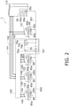
- the outdoor unit 110 includes an outdoor controller 55.
- the outdoor controller 55 includes a microcontroller unit (MCU) 55a, a transmitter 55b, and a transceiver 55c.
- the transmitter 55b and the transceiver 55c of the outdoor unit 110 are connected to the first line 501.
- the first indoor unit 121 includes an indoor controller 65.
- the indoor controller 65 includes a microcontroller unit (MCU) 65a, a receiver 65b, and a transceiver 65c.
- the receiver 65b and the transceiver 65c of the first indoor unit 121 are connected to the first line 501.
- Each of the second indoor units 122 includes an indoor controller 65.
- the indoor controller 65 includes a microcontroller unit (MCU) 65a, a receiver 65b, and a transceiver 65c.
- the receivers 65b and the transceivers 65c of the second indoor units 122 are connected to the second line 502.
- the first intermediary unit 150 includes an intermediary controller 70.
- the intermediary controller 70 includes a microcontroller unit (MCU) 70a, a receiver 70b, a transceiver 70c, and a transmitter 70d.
- the receiver 70b and the transceiver 70c of the first intermediary unit 150 are connected to the first line 501.
- the transmitter 70d of the first intermediary unit 150 is connected to the second line 502.
- the transceivers 55c, 65c, and 70c perform communication via high-frequency first signals.
- the transmitters 55b and 70d and the receivers 65b and 70b perform communication via low-frequency second signals.
- An MCU includes, for example, a control arithmetic unit and a storage device (memory).
- the control arithmetic unit can be implemented using a processor such as a CPU or a GPU.
- the control arithmetic unit reads a program stored in the storage device and performs predetermined image processing and arithmetic processing in accordance with the program. Further, the control arithmetic unit can write an arithmetic result to the storage device or read information stored in the storage device in accordance with the program.
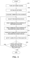
- the air conditioning system 1 circulates refrigerant to perform air conditioning. Before performing the air conditioning operation, the air conditioning system 1 recognizes a communication target in accordance with the circulation of the refrigerant. The recognition of the communication target in accordance with the circulation of the refrigerant is system recognition. Communication of the air conditioning system 1 for performing system recognition will be described with reference to Fig. 3 .
- the power source for the air conditioning system 1 is turned on (step ST1).
- the outdoor controller 55 uses the transceiver 55c to transmit and receive communication signals to and from the transceivers 65c of the plurality of indoor controllers 65 and the transceiver 70c of the intermediary controller 70 to establish a network.
- the outdoor unit 110, the first indoor unit 121, the plurality of second indoor units 122, and the first intermediary unit 150 each acquire a communication address (step ST3).
- the MCU 55a of the outdoor controller 55, the MCUs 65a of the plurality of indoor controllers 65, and the MCU 70a of the intermediary controller 70 have a function of, for example, automatically acquiring a communication address. Using this function, the outdoor unit 110, the first indoor unit 121, the plurality of second indoor units 122, and the first intermediary unit 150 can acquire communication addresses that do not overlap each other.
- the outdoor unit 110 and the first intermediary unit 150 cooperate with each other via communication using the transceiver 55c and the transceiver 70c and select one recognition device on the network (step ST4).
- the outdoor unit 110 is selected.
- the first intermediary unit 150 changes the role from a recognition device to a recognition-target device. Changing the role from a recognition device to a recognition-target device means entering a state in which the receiver 70b is ready to receive a second signal sent from the transmitter 55b of the outdoor unit 110.
- the selected recognition device uses the transmitter to transmit a second signal to devices in the layer to which the recognition device belongs for refrigerant system recognition (step ST5).
- the outdoor unit 110 uses the transmitter 55b to transmit a second signal to the first line 501 for refrigerant system recognition.
- the second signal transmitted from the transmitter 55b is a low-frequency signal and is thus difficult to pass through the first filter 151.
- the second signal is attenuated by the first filter 151 and thus is not received as a valid signal at the receivers 65b of the second indoor units 122.
- the second signal transmitted from the transmitter 55b of the outdoor controller 55 of the outdoor unit 110 is not receivable at the receivers 65b of the second indoor units 122.
- the outdoor unit 110 transmits its communication address via a first signal by using the transceiver 55c simultaneously with the transmission of the second signal or before or after the transmission of the second signal.
- the outdoor unit 110 may be configured to send the communication address via a low-frequency signal having a frequency other than 0.
- the first indoor unit 121 which has received the second signal at the receiver 65b and has received the communication address of the outdoor unit 110 at the transceiver 65c or the receiver 65b through the first line 501, stores the received communication address in a memory of the MCU 63a.
- the first intermediary unit 150 which has received the second signal at the receiver 70b and has received the communication address of the outdoor unit 110 at the transceiver 70c or the receiver 70b through the first line 501, stores the received communication address in a memory of the MCU 70a.
- a recognition-target device that has received the second signal and the communication address of the recognition device transmits its communication address to the communication address of the recognition device (step ST6).
- the first indoor unit 121 and the first intermediary unit 150 transmit their communication addresses to the communication address of the outdoor unit 110 through the first line 501 by using the transceiver 65c and the transceiver 70c.
- the selected recognition device registers the sent communication address of the recognition-target device in the same system list in which indoor units in the same layer are registered (step ST7).
- the outdoor unit 110 sequentially adds the communication addresses of the first indoor unit 121 and the first intermediary unit 150, which are sent to the communication address of the outdoor unit 110 through the first line 501, to the same system list.
- the outdoor unit 110 holds the same system list, thereby recognizing that the outdoor unit 110 is a first-layer device belonging to the first layer.
- the selected recognition device notifies, upon completion of the registration of all the recognition-target devices in the layer to which the recognition device belongs, the entire network that the system recognition for the layer to which the recognition device belongs is completed (step ST8).
- the outdoor unit 110 upon completion of the registration of the first indoor unit 121 in the first layer and the first intermediary unit 150, the outdoor unit 110 notifies the entire network that the system recognition for the first layer is completed, through the first line 501 and the second line 502 by using the transceiver 55c.
- step ST9 It is determined whether there is a recognition device that has not completed system recognition.
- the outdoor unit 110 is selected, even if the outdoor unit 110 has first completed the system recognition, the first intermediary unit 150 has not completed the system recognition for the second layer (Yes in step ST9).
- the outdoor unit 110 and the first intermediary unit 150 cooperate with each other via communication using the transceiver 55c and the transceiver 70c and select the first intermediary unit 150 as a recognition device (step ST4).
- the first intermediary unit 150 changes the role from a recognition-target device to a recognition device.
- the selected first intermediary unit 150 uses the transmitter 70d to transmit a second signal to devices in a layer lower than the layer of the first intermediary unit 150 through the second line 502 (step ST5).
- the second signal transmitted from the transmitter 55b is a low-frequency signal and is thus difficult to pass through the first filter 151.
- the second signal transmitted from the transmitter 70d of the intermediary controller 70 of the first intermediary unit 150 is not receivable at the receiver 65b of the first indoor unit 121.
- the first intermediary unit 150 uses the transceiver 70c to transmit its communication address via a first signal simultaneously with the transmission of the second signal or before or after the transmission of the second signal.
- the first intermediary unit 150 may be configured to send the communication address via a low-frequency signal having a frequency other than 0.
- the plurality of second indoor units 122 which have received the second signal at the receivers 65b and have received the communication address of the first intermediary unit 150 at the transceivers 65c or the receivers 65b through the second line 502, store the received communication address in memories of the respective MCUs 63a.
- the plurality of second indoor units 122 which have received the second signal and the communication address of the first intermediary unit 150, transmit their communication addresses to the communication address of the first intermediary unit 150 (step ST6).
- the first intermediary unit 150 registers the communication addresses of the plurality of second indoor units 122, which are sent through the second line 502, in the same system list in which second-layer devices in the second layer are registered (step ST7).
- the first intermediary unit 150 notifies, upon completion of the registration of all of the second indoor units 122 in the second layer, the entire network that the system recognition for the second layer is completed (step ST8).
- the first intermediary unit 150 notifies the entire network that the system recognition for the second layer is completed through the first line 501 and the second line 502 by using the transceiver 70c.
- the first intermediary unit 150 transmits the communication addresses of the second indoor units 122 in the second layer to the MCU 55a of the outdoor controller 55 of the outdoor unit 110 through the first line 501 by using the transceiver 70c.
- the outdoor unit 110 registers the communication addresses of the plurality of second indoor units 122, which are received from the first intermediary unit 150, in the same system list as the communication addresses of the second-layer devices.
- step ST9 The determination of whether there is a recognition device that has not completed system recognition (step ST9) is performed after the outdoor unit 110 and the first intermediary unit 150 have completed the system recognition. Accordingly, since all of the recognition devices illustrated in Fig. 1 , namely, the outdoor unit 110 and the first intermediary unit 150, have completed the system recognition (No in step ST9), the air conditioning system 1 terminates the communication for system recognition.
- the identification of a communication destination and/or a communication source is not limited to the identification using communication addresses.
- the air conditioning system 1 may be configured to identify a communication destination and/or a communication source using unique IDs of the outdoor unit 110, the first indoor unit 121, the plurality of second indoor units 122, and the first intermediary unit 150.
- the communication address of the first indoor unit 121 connected to the first line 501 is registered as a first-layer device, and the communication addresses of the second indoor units 122 are registered as second-layer devices, and the communication address of the first intermediary unit 150 is registered as a first intermediary device in the same system list in the MCU 55a of the outdoor unit 110.
- the outdoor unit 110 can use the same system list stored in the MCU 55a to identify the first indoor unit 121, the plurality of second indoor units 122, and the first intermediary unit 150 belonging to the same refrigerant system and control the vapor compression refrigeration cycle of the refrigerant system.
- the outdoor unit 110 can use the same system list to send instructions to the first indoor unit 121, which is a first-layer device, the plurality of second indoor units 122, which are second-layer devices, and the first intermediary unit 150, which is a first intermediary device, in a distinguishable manner using communication signals through the first line 501 and the second line 502.
- the outdoor unit 110 can use the transceiver 55c to instruct the first indoor unit 121, the plurality of second indoor units 122, and the first intermediary unit 150, which are registered in the same system list, to address the abnormal discharge temperature of the compressor using communication signals through the first line 501 and the second line 502.
- the outdoor unit 110 can use the transceiver 55c to instruct only the first indoor unit 121, which is a first-layer device registered in the same system list, to change the air conditioning capacity using a communication signal through the first line 501.
- the outdoor unit 110 can further use the transceiver 55c to instruct the plurality of second indoor units 122, which are second-layer devices, and the first intermediary unit 150, which are registered in the same system list, to change the air conditioning capacity using communication signals through the first line 501 and the second line 502.
- the first embodiment described above presents a case where the outdoor unit 110 and the first indoor unit 121 are first-layer devices, the first intermediary unit 150 is a first intermediary device, and the plurality of second indoor units 122 are second-layer devices.
- a first-layer device, a second-layer device, and a first intermediary device are not limited to those in the first embodiment.
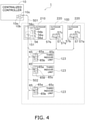
- an air conditioning system 1 according to a second embodiment illustrated in Fig. 4 may be used.
- the air conditioning system 1 includes a centralized controller 10, an outdoor unit 210, a plurality of outdoor units 220, a plurality of third indoor units 123, a first line 501, and a second line 502.
- the centralized controller 10 is a first-layer device
- the outdoor unit 210 is a first intermediary device
- the plurality of outdoor units 220 are second-layer devices.
- the first line 501 and the second line 502 are physical wires.
- the first line 501 is connected to the centralized controller 10 and the outdoor unit 210.
- the second line 502 is connected to the plurality of outdoor units 220 and the plurality of third indoor units 123.
- the outdoor unit 210 includes a first filter 151.
- the first filter 151 is always connected to the first line 501 and the second line 502.
- the outdoor unit 210 communicates with the centralized controller 10, which is a first-layer device, and also communicates with the plurality of outdoor units 220 and the plurality of third indoor units 123, which are second-layer devices.
- the relationship between a first signal and a second signal, which are used for communication in the air conditioning system 1, and the relationship between these signals and the first filter 151 are similar to those in the first embodiment.
- refrigerant circulates among the outdoor unit 210, the plurality of outdoor units 220, and the plurality of third indoor units 123.
- a vapor compression refrigeration cycle is performed by such circulation of the refrigerant.
- the circulation of the refrigerant causes thermal energy transfer between the outdoor units 210 and 220 and the third indoor units 123.
- Each of the third indoor units 123 includes a heat exchanger (not illustrated). In each of the third indoor units 123, the heat exchanger exchanges heat between the refrigerant and indoor air to perform at least one of cooling, heating, and dehumidification of the indoor space.
- the centralized controller 10 includes a microcontroller unit (MCU) 10a, a transmitter 10b, and a transceiver 10c.
- the transmitter 10b and the transceiver 10c of the centralized controller 10 are connected to the first line 501.
- the outdoor unit 210 includes an outdoor controller 56.
- the outdoor controller 56 includes a microcontroller unit (MCU) 56a, a receiver 56b, a transceiver 56c, and a transmitter 56d.
- the receiver 56b and the transceiver 56c of the outdoor unit 210 are connected to the first line 501.
- the transmitter 56d of the outdoor unit 210 is connected to the second line 502.
- Each of the outdoor units 220 includes an outdoor controller 57.
- the outdoor controller 57 includes a microcontroller unit (MCU) 57a, a receiver 57b, and a transceiver 57c.
- the receivers 57b and the transceivers 57c of the outdoor units 220 are connected to the second line 502.
- Each of the third indoor units 123 includes an indoor controller 65.
- the indoor controller 65 includes a microcontroller unit (MCU) 65a, a receiver 65b, and a transceiver 65c.
- the receivers 65b and the transceivers 65c of the third indoor units 123 are connected to the second line 502.
- the transceivers 10c, 56c, 57c, and 65c perform communication via high-frequency first signals.
- the transmitter 10b and the receiver 56b perform communication via low-frequency second signals, and the transmitter 56d and the receivers 57b and 65b perform communication via low-frequency second signals.
- Communication for system recognition according to the second embodiment can be performed by an operation similar to the operation of communication for system recognition according to the first embodiment.
- the operation of the transmitter 55b and the transceiver 55c of the outdoor controller 55 according to the first embodiment is performed by the transmitter 10b and the transceiver 10c of the centralized controller 10 according to the second embodiment.
- the operation of the receiver 70b, the transceiver 70c, and the transmitter 70d of the intermediary controller 70 according to the first embodiment is performed by the receiver 56b, the transceiver 56c, and the transmitter 56d of the outdoor controller 56 according to the second embodiment.
- the operation of the receivers 65b and the transceivers 65c of the indoor controllers 65 of the second indoor units 122 according to the first embodiment is performed by the receivers 57b and the transceivers 57c of the outdoor controllers 57 and the receivers 65b and the transceivers 65c of the indoor controllers 65 according to the second embodiment.
- the communication for system recognition can be performed in accordance with the flowchart illustrated in Fig. 3 .
- the centralized controller 10 is a recognition device, and the outdoor unit 210 is a device having two aspects, namely, a recognition device and a recognition-target device.
- the plurality of outdoor units 220 and the plurality of third indoor units 123 are recognition-target devices.
- the centralized controller 10 performs system recognition to recognize devices belonging to a refrigerant system 100. Although there is no first-layer device to be registered in the same system list in the centralized controller 10, the centralized controller 10 holds the same system list, thereby recognizing that the centralized controller 10 is a first-layer device belonging to the first layer.
- the centralized controller 10 may be configured to notify the outdoor units 210 and 220 of devices belonging to the refrigerant system 100 recognized by the centralized controller 10.
- the first embodiment and the second embodiment described above present a case where the air conditioning system 1 includes two layers including the first-layer device(s) and the second-layer devices.
- an air conditioning system according to the present disclosure may not necessarily include two layers, and may include three or more layers.
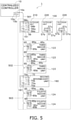
- a second intermediary unit 160 which is a second intermediary device
- fourth indoor units 124 which are third-layer devices, are installed in positions lower than the third indoor units 123, which are second-layer devices according to the second embodiment.
- An air conditioning system 1 according to the third embodiment is the same as the air conditioning system 1 according to the second embodiment in that the air conditioning system 1 according to the third embodiment includes the centralized controller 10 to the third indoor units 123, namely, a first-layer device, a first intermediary device, and second-layer devices.
- the fourth indoor units 124 which are third-layer devices
- the second intermediary unit 160 which is a second intermediary device
- a physical third line 503 are added to the air conditioning system 1 according to the second embodiment.
- the third line 503 is connected to the plurality of fourth indoor units 124.
- the second intermediary unit 160 includes a second filter 161.
- the second filter 161 is always connected to the second line 502 and the third line 503.
- the second intermediary unit 160 communicates with the centralized controller 10, which is a first-layer device, and also communicates with the outdoor unit 210, which is a first intermediary device, and the plurality of outdoor units 220 and the plurality of third indoor units 123, which are second-layer devices.
- the relationship between a first signal and a second signal, which are used for communication in the air conditioning system 1, and the relationship between these signals and the second filter 161 are similar to the relationship between the first signal and the second signal according to the second embodiment and the relationship between these signals and the first filter 151.
- the second filter 161 does not attenuate a high-frequency first signal, and attenuates a low-frequency second signal.
- the second filter 161 is installed so as not to attenuate a high-frequency first signal and so as to attenuate a low-frequency second signal, which indicates that, for example, the second filter 161 is installed so that the attenuation factor for the high-frequency first signal is smaller than the attenuation factor for the low-frequency second signal.
- the second intermediary unit 160 is configured to be capable of communicating with the first intermediary unit 150, which is a first intermediary device, via a second signal.
- the second filter 161 can include, for example, a capacitor, an attenuator that attenuates low-frequency signals, an active filter, and a switching device that disconnects the second line 502 and the third line 503 from each other to carry a low-frequency signal over the second line 502 and the third line 503.
- the switching device can be implemented using, for example, a relay.
- refrigerant circulates among the outdoor unit 210, the plurality of outdoor units 220, the plurality of third indoor units 123, the second intermediary unit 160, and the fourth indoor units 124.
- a vapor compression refrigeration cycle is performed by such circulation of the refrigerant.
- the circulation of the refrigerant causes thermal energy transfer between the outdoor units 210 and 220, the third indoor units 123, the second intermediary unit, and the fourth indoor units 124.
- the third indoor units 123 and the fourth indoor units 124 each includes a heat exchanger (not illustrated). In each of the third indoor units 123 and the fourth indoor units 124, the heat exchanger exchanges heat between the refrigerant and indoor air to perform at least one of cooling, heating, and dehumidification of the indoor space.
- the centralized controller 10, the outdoor controller 56 of the outdoor unit 210, the outdoor controllers 57 of the outdoor units 220, and the indoor controllers 65 of the third indoor units 123 have been described in the second embodiment, and the description thereof is thus omitted here.
- the intermediary controller 70 included in the second intermediary unit 160 has the same configuration as that of the intermediary controller 70 of the first intermediary unit 150, and the description thereof is thus omitted here.
- the transceivers 10c, 56c, 57c, 65c, and 70c perform communication via high-frequency first signals.
- the transmitter 10b and the receiver 56b perform communication via low-frequency second signals
- the transmitter 56d and the receivers 57b and 65b perform communication via low-frequency second signals
- the transmitter 70d and the receivers 65b perform communication via low-frequency second signals.
- the recognition of a first-layer device by the centralized controller 10 and the recognition of a second-layer device by the outdoor unit 210 can be performed in a way similar to that in the communication for system recognition according to the second embodiment described above.
- the recognition of a third-layer device by the second intermediary unit 160 can be performed by an operation similar to that in the recognition of a second-layer device by the first intermediary unit 150 according to the second embodiment.
- step ST9 in Fig. 3 for determining whether there is a recognition device that has not completed system recognition it is assumed that the centralized controller 10 and the outdoor unit 210 have completed system recognition and the second intermediary unit 160 has not completed system recognition.
- the centralized controller 10, the outdoor unit 210, and the second intermediary unit 160 cooperate with each other via communication using the transceivers 10c, 55c, and 70c and select the second intermediary unit 160 as a recognition device (step ST4).
- the second intermediary unit 160 When the second intermediary unit 160 is selected as a recognition device, the second intermediary unit 160 changes the role from a recognition-target device to a recognition device.
- the selected second intermediary unit 160 uses the transmitter 70d to transmit a second signal to devices in a layer lower than the layer of the second intermediary unit 160 through the third line 503 (step ST5). Due to the attenuation effect of the second filter 161, the receivers 65b of the third indoor units 123 are not allowed to receive the second signal transmitted from the transmitter 70d of the intermediary controller 70 of the second intermediary unit 160.
- the second intermediary unit 160 transmits its communication address via a first signal by using the transceiver 70c simultaneously with the transmission of the second signal or before or after the transmission of the second signal.
- the second intermediary unit 160 may be configured to send the communication address via a low-frequency signal having a frequency other than 0.
- the plurality of fourth indoor units 124 which have received the second signal at the receivers 65b through the third line 503 and have received the communication address of the second intermediary unit 160 at the transceivers 65c or the receivers 65b, store the received communication address in memories of the respective MCUs 63a.
- the plurality of fourth indoor units 124 which have received the second signal and the communication address of the second intermediary unit 160, transmit their communication addresses to the communication address of the second intermediary unit 160 (step ST6).
- the second intermediary unit 160 registers the communication addresses of the plurality of fourth indoor units 124, which are sent through the third line 503, in the same system list in which second-layer devices in the second layer are registered (step ST7).
- the second intermediary unit 160 notifies, upon completion of the registration of all of the fourth indoor units 124 in the second layer, the entire network that the system recognition for the second layer is completed (step ST8).
- the second intermediary unit 160 notifies the entire network that the system recognition for the second layer is completed through the first line 501, the second line 502, and the third line 503 by using the transceiver 70c.
- the second intermediary unit 160 transmits the communication addresses of the fourth indoor units 124 in the second layer to the MCU 56a of the outdoor controller 56 of the outdoor unit 210 through the second line 502 by using the transceiver 70c.
- the outdoor unit 210 registers the communication addresses of the plurality of fourth indoor units 124, which are received from the second intermediary unit 160, in the same system list as the communication addresses of third-layer devices.
- the MCU 56a of the outdoor controller 56 of the outdoor unit 210 transmits the communication addresses of the fourth indoor units 124 in the second layer to the MCU 10a of the centralized controller 10 through the first line 501 by using the transceiver 56c.
- the centralized controller 10 registers the communication addresses of the plurality of fourth indoor units 124, which are received from the outdoor unit 210, in the same system list as the communication addresses of third-layer devices.
- the centralized controller 10 is a recognition device
- the outdoor unit 210 and the second intermediary unit 160 are devices having two aspects, namely, a recognition device and a recognition-target device.
- the plurality of outdoor units 220, the plurality of third indoor units 123, and the plurality of fourth indoor units 124 are recognition-target devices.
- the air conditioning system 1 has been described as a network system, by way of example.
- the network system is not limited to an air conditioning system.
- Examples of the network system to which the technology of the present disclosure is applicable include a hot-water supply system and a ventilation system.
- a first intermediary device and second-layer devices are provided only in one row.
- a first intermediary device and second-layer devices can be configured to be provided in a plurality of rows in parallel.
- a first intermediary device and second-layer devices may be configured to be provided in a plurality of rows in parallel.
- two first intermediary units 150 which are first intermediary devices, are connected to the first line 501.
- Each of the first intermediary units 150 is connected to three second indoor units 122 by the second line 502.
- the first intermediary device is the first intermediary unit 150 or the outdoor unit 210.
- the first intermediary device is not limited to such devices.
- the first intermediary device may be implemented using a power supply unit that supplies a direct-current voltage or an alternating-current voltage to indoor units.
- the first intermediary unit 150 and/or the outdoor units 110 and 210 include the transmitters 55b, 56d, and 70d that transmit low-frequency signals.
- a device for performing recognition is not determined before the air conditioning system 1 is constructed.
- an outdoor unit 210 on the side that performs recognition and an outdoor unit 210 on the side that is recognized may be determined.
- each of the plurality of outdoor units 210 can be configured to include a low-frequency transceiver 56e, in place of a low-frequency transmitter, for system recognition (see Fig. 8 ).
- an intermediary device such as the first intermediary unit 150, can also be configured to include a low-frequency transceiver for system recognition.
- the centralized controller 10 includes the transmitter 10b that transmits a low-frequency signal.
- a device for performing recognition is not determined before the air conditioning system 1 is constructed.
- a centralized controller 10 on the side that performs recognition and a centralized controller 10 on the side that is recognized may be determined.
- each of the plurality of centralized controllers 10 can be configured to include a low-frequency transceiver 10e, in place of a low-frequency transmitter, for system recognition (see Fig. 9 ).
- a second intermediary device and third-layer devices can be configured to be provided in a plurality of rows in parallel.
- a second intermediary device and third-layer devices may be configured to be provided in a plurality of rows in parallel.
- two second intermediary units 160 which are second intermediary devices, are connected to the second line 502.
- Each of the second intermediary units 160 is connected to two fourth indoor units 124 by the third line 503.
- the second intermediary device is the second intermediary unit 160.
- the second intermediary device is not limited to this.
- the second intermediary device may be implemented using a power supply unit that supplies a direct-current voltage or an alternating-current voltage to indoor units.
- the first line 501 and the second line 502 can always be connected by the first filter 151.
- the air conditioning system 1 according to the first embodiment or the modification illustrated in Fig. 1 or Fig. 6 therefore, even if a failure has occurred in the first intermediary unit(s) 150, which is a first intermediary device, a state can be maintained in which communication is possible between the outdoor unit 110, which is a first-layer device, and the plurality of second indoor units 122, which are second-layer devices.
- the air conditioning system 1 can improve the reliability of communication.
- the outdoor unit 110 or the centralized controller 10 can maintain control.
- the outdoor unit 110 or the centralized controller 10 can use a first signal to stop the operation of the plurality of second indoor units 122 or the plurality of third indoor units 123 through the first line 501 and the second line 502 or change the opening degrees of the expansion valves while operating the plurality of second indoor units 122 or the plurality of third indoor units 123.
- the second line 502 and the third line 503 are always connected by the second filter(s) 161.
- the air conditioning system 1 according to the third embodiment or the modification thereof illustrated in Fig. 5 or Fig. 7 therefore, even if a failure has occurred in the second intermediary unit(s) 160, which is a second intermediary device, a state can be maintained in which communication is possible between the centralized controller 10, which is a first-layer device, and the outdoor unit 210 and the plurality of fourth indoor units 124, which are second-layer devices. Accordingly, the air conditioning system 1 according to the third embodiment or the modification thereof can improve the reliability of communication.
- the outdoor unit 110 or the centralized controller 10, which is a first-layer device, of the air conditioning system 1 can recognize the second indoor units 122 or the third indoor units 123, which are second-layer devices, connected to the first intermediary unit 150 or the outdoor unit 210, which is a first intermediary device, by the second line 502 by using the first intermediary unit 150 or the outdoor unit 210. Therefore, for example, even if another device is connected between the outdoor unit 110 or the centralized controller 10 and the first intermediary unit 150 or the outdoor unit 210, the outdoor unit 110 or the centralized controller 10 can recognize and manage the second indoor units 122 or the third indoor units 123 in a way distinguishable from the other device.
Landscapes
- Engineering & Computer Science (AREA)
- Chemical & Material Sciences (AREA)
- Combustion & Propulsion (AREA)
- Mechanical Engineering (AREA)
- General Engineering & Computer Science (AREA)
- Human Computer Interaction (AREA)
- Computer Networks & Wireless Communication (AREA)
- Signal Processing (AREA)
- Air Conditioning Control Device (AREA)
- Small-Scale Networks (AREA)
- Cable Transmission Systems, Equalization Of Radio And Reduction Of Echo (AREA)
Abstract
Description
- The present disclosure relates to a network system
- In the related art, there are known network systems for performing information transmission between devices, examples of which include, as described in PTL 1 (
Japanese Unexamined Patent Application Publication No. 2016-219983 - In a network in which a plurality of devices are connected by a communication line, the plurality of devices may be divided into a plurality of layers, for example, a first layer and a second layer, with an intermediary device therebetween, the intermediary device being disposed in the middle of the network. In such a network, in some cases, it is desired to perform overall communication using a common line without distinguishing between devices belonging to the first layer and devices belonging to the second layer. In such a network, furthermore, in some cases, it is desired to perform communication among only devices belonging to the first layer using the line described above. In such a network, furthermore, in some cases, it is desired to perform communication among only devices belonging to the second layer using the line described above.
- In such a network system, however, if the same communication line is used, a signal transmitted from a device belonging to the first layer may be received by a device belonging to the second layer, and communication desired to be performed among devices belonging to the first layer may not be successful. Likewise, if the same communication line is used, a signal transmitted from a device belonging to the second layer may be received by a device belonging to the first layer, and communication desired to be performed among devices belonging to the second layer may not be successful.
- Accordingly, it is conceivable that the communication line is separated by an intermediary device and the intermediary device has a function of transferring a communication signal. If the intermediary device has a function of transferring a communication signal, however, in a case where it is desired to perform overall communication without distinguishing between devices belonging to the first layer and devices belonging to the second layer, a failure in the intermediary device may cause a failure in communication between devices belonging to different layers.
- It is an object to improve the reliability of communication in a network in which a plurality of devices are classified into a plurality of layers, in a case where communication independent of the layers and communication within the layers are performed through physical lines.
- A network system according to a first aspect includes a first-layer device, a first line, a second-layer device, a second line, and a first intermediary device. The first line is connected to the first-layer device. The second line is connected to the second-layer device. The first intermediary device includes a first filter always connected to the first line and the second line, and is configured to communicate with the first-layer device and the second-layer device. The first filter is installed so as not to attenuate a high-frequency first signal used for communication among the first-layer device, the first intermediary device, and the second-layer device and so as to attenuate a low-frequency second signal used for communication between the first intermediary device and the second-layer device, other than the first-layer device.
- In the network system according to the first aspect, since the first line and the second line can always be connected by the first filter, even if a failure has occurred in the first intermediary device, a state can be maintained in which communication is possible between the first-layer device and the second-layer device. As a result, the network system can improve the reliability of communication.
- A network system according to a second aspect is the system according to the first aspect, in which the second-layer device is a plurality of indoor units that air-condition an inside of a room.
- In the network system according to the second aspect, even if a failure has occurred in the first intermediary device, a state can be maintained in which communication with the plurality of indoor units is possible, and it is possible to prevent a failure caused due to, for example, the plurality of indoor units being no longer controllable.
- A network system according to a third aspect is the system according to the first aspect or the second aspect, further including a third-layer device, a third line, and a second intermediary device. The third line is connected to the third-layer device. The second intermediary device includes a second filter always connected to the second line and the third line, and is configured to communicate with the first intermediary device and the third-layer device. The second filter is installed so as not to attenuate the high-frequency first signal used for communication among the first-layer device, the first intermediary device, the second-layer device, the second intermediary device, and the third-layer device and so as to attenuate a low-frequency third signal used for communication between the second intermediary device and the third-layer device, other than the first-layer device, the first intermediary device, and the second-layer device.
- In the network system according to the third aspect, since the second line and the third line can always be connected by the second filter, even if a failure has occurred in the second intermediary device, a state can be maintained in which communication is possible between the second-layer device and the third-layer device.
- A network system according to a fourth aspect is the system according to the third aspect, in which the first-layer device is an outdoor unit or a centralized controller capable of controlling the second-layer device and the third-layer device.
- In the network system according to the fourth aspect, even if a failure has occurred in the first intermediary device and/or the second intermediary device, a state can be maintained in which the outdoor unit or the centralized controller can communicate with the plurality of indoor units. In the network system according to the fourth aspect, it is possible to prevent a failure caused by, for example, the outdoor unit or the centralized controller being no longer able to control the plurality of indoor units.
- A network system according to a fifth aspect is the system according to any one of the first to fourth aspects, in which the first intermediary device recognizes the second-layer device using the second signal. The first-layer device recognizes the second-layer device via communication with the first intermediary device.
- In the network system according to the fifth aspect, the first-layer device can recognize the second-layer device connected to the first intermediary device by the second line through the first intermediary device. For example, even if another device is connected between the first-layer device and the first intermediary device, the first-layer device can recognize and manage the second-layer device in a way distinguishable from the other device.
-
- [
Fig. 1] Fig. 1 is a conceptual diagram illustrating an overview of an example configuration of an air conditioning system according to a first embodiment. - [
Fig. 2] Fig. 2 is a circuit diagram of the air conditioning system illustrated inFig. 1 . - [
Fig. 3] Fig. 3 is a flowchart for illustrating communication for system recognition in the air conditioning system. - [
Fig. 4] Fig. 4 is a circuit diagram illustrating an overview of an example configuration of an air conditioning system according to a second embodiment. - [
Fig. 5] Fig. 5 is a circuit diagram illustrating an overview of an example configuration of an air conditioning system according to a third embodiment. - [
Fig. 6] Fig. 6 is a circuit diagram illustrating an overview of an example configuration of an air conditioning system according to a modification. - [
Fig. 7] Fig. 7 is a circuit diagram illustrating an overview of another example configuration of an air conditioning system according to a modification. - [
Fig. 8] Fig. 8 is a block diagram for illustrating an overview of another example configuration of an air conditioning system according to a modification. - [
Fig. 9] Fig. 9 is a block diagram for illustrating an overview of another example configuration of an air conditioning system according to a modification. - A network system according to a first embodiment will be described with reference to an
air conditioning system 1 illustrated inFig. 1 . Theair conditioning system 1 according to the first embodiment includes anoutdoor unit 110, one firstindoor unit 121, afirst intermediary unit 150, a plurality of secondindoor units 122, afirst line 501, and asecond line 502. - The
outdoor unit 110 and the firstindoor unit 121 are first-layer devices. Thefirst line 501 is a physical wire. Thefirst line 501 is connected to theoutdoor unit 110 and the firstindoor unit 121. The plurality of secondindoor units 122 are second-layer devices. Thesecond line 502 is a physical wire. Thesecond line 502 is connected to the plurality of secondindoor units 122. Thefirst line 501 and thesecond line 502 may be each constituted by a plurality of wires extending in parallel. - The
first intermediary unit 150 includes afirst filter 151. Thefirst filter 151 is always connected to thefirst line 501 and thesecond line 502. Thefirst intermediary unit 150 is configured to be capable of communicating with theoutdoor unit 110, which is a first-layer device, via a second signal. Thefirst intermediary unit 150 is a first intermediary device. - The
first filter 151 does not attenuate a high-frequency first signal, which is used for communication among theoutdoor unit 110, the firstindoor unit 121, thefirst intermediary unit 150, and the plurality of secondindoor units 122. Thefirst filter 151 attenuates a low-frequency second signal, which is used for communication between thefirst intermediary unit 150 and the plurality of secondindoor units 122, other than theoutdoor unit 110 and the firstindoor unit 121. In the present disclosure, high frequencies are defined to be frequencies higher than or equal to 100 kHz, and low frequencies are defined to be frequencies lower than or equal to 10 kHz. The low frequencies include 0 kHz (direct current). Thefirst filter 151 is installed so as not to attenuate a high-frequency first signal and so as to attenuate a low-frequency second signal, which indicates that, for example, thefirst filter 151 is installed so that the attenuation factor for the high-frequency first signal is smaller than the attenuation factor for the low-frequency second signal. - The
first filter 151 is a device that passes high-frequency signals and blocks low-frequency signals. Examples of the filter that passively passes high-frequency signals and blocks low-frequency signals include a capacitor, and an attenuator that attenuates low-frequency signals. The filter used as thefirst filter 151 may be an active filter including an active element. For example, an inductive coupler that passes high-frequency signals and blocks direct-current signals can also be used as the filter 403. There is a switching device that switches connection and disconnection between thefirst line 501 and thesecond line 502. The switching device is a device that disconnects thefirst line 501 and thesecond line 502 from each other to carry a low-frequency signal over thefirst line 501 and thesecond line 502. In the switching device, for example, a relay can be used to switch connection and disconnection between thefirst line 501 and thesecond line 502. -
Fig. 1 exemplarily illustrates a case where one firstindoor unit 121 is used. However, theair conditioning system 1 may be configured to include a plurality of firstindoor units 121. Alternatively, theair conditioning system 1 may be configured not to include the firstindoor unit 121. - In the
air conditioning system 1 according to the first embodiment, refrigerant circulates among theoutdoor unit 110, the firstindoor unit 121, the firstintermediary unit 150, and the plurality of secondindoor units 122. To circulate refrigerant, theair conditioning system 1 includesrefrigerant pipes outdoor unit 110 and the firstindoor unit 121 are connected by therefrigerant pipes - The
outdoor unit 110 and the firstintermediary unit 150 are connected by therefrigerant pipes indoor units 122 and the firstintermediary unit 150 are connected by therefrigerant pipes air conditioning system 1, a vapor compression refrigeration cycle is performed by the circulation of the refrigerant. In theair conditioning system 1, the circulation of the refrigerant causes thermal energy transfer between theoutdoor unit 110, and the firstindoor unit 121 and the plurality of secondindoor units 122. - While the internal configuration of the
outdoor unit 110 is not illustrated, theoutdoor unit 110 is configured to include, for example, a compressor, a four-way valve, a heat exchanger, an expansion valve, and a fan. Theoutdoor unit 110 is a device that performs heat exchange between outdoor air and the refrigerant. Theoutdoor unit 110 sucks gaseous refrigerant flowing through therefrigerant pipe 143 and supplies low-temperature liquid refrigerant flowing through therefrigerant pipe 141 and high-temperature gaseous refrigerant flowing through therefrigerant pipe 142. - While the internal configuration of the first
indoor unit 121 and the secondindoor units 122 is not illustrated, each of the firstindoor unit 121 and the secondindoor units 122 includes, for example, a heat exchanger, an expansion valve, and a fan. The firstindoor unit 121 and the secondindoor units 122 are each a device that performs heat exchange between indoor air and the refrigerant. In each of the firstindoor unit 121 and the secondindoor units 122, for example, the heat exchanger exchanges heat between the refrigerant and the indoor air, and the fan blows heat-exchanged air to the outside. The firstindoor unit 121 and the secondindoor units 122 perform cooling using low-temperature refrigerant or perform heating using high-temperature refrigerant. - The first
intermediary unit 150 is a device that adjusts refrigerant to be caused to flow into the plurality of secondindoor units 122 connected to the firstintermediary unit 150, such as switching the flow of the refrigerant to be caused to flow into the plurality of secondindoor units 122. - The
outdoor unit 110 includes anoutdoor controller 55. Theoutdoor controller 55 includes a microcontroller unit (MCU) 55a, atransmitter 55b, and atransceiver 55c. Thetransmitter 55b and thetransceiver 55c of theoutdoor unit 110 are connected to thefirst line 501. - The first
indoor unit 121 includes anindoor controller 65. Theindoor controller 65 includes a microcontroller unit (MCU) 65a, areceiver 65b, and atransceiver 65c. Thereceiver 65b and thetransceiver 65c of the firstindoor unit 121 are connected to thefirst line 501. - Each of the second
indoor units 122 includes anindoor controller 65. Theindoor controller 65 includes a microcontroller unit (MCU) 65a, areceiver 65b, and atransceiver 65c. Thereceivers 65b and thetransceivers 65c of the secondindoor units 122 are connected to thesecond line 502. - The first
intermediary unit 150 includes anintermediary controller 70. Theintermediary controller 70 includes a microcontroller unit (MCU) 70a, areceiver 70b, atransceiver 70c, and atransmitter 70d. Thereceiver 70b and thetransceiver 70c of the firstintermediary unit 150 are connected to thefirst line 501. Thetransmitter 70d of the firstintermediary unit 150 is connected to thesecond line 502. - The
transceivers transmitters receivers - An MCU includes, for example, a control arithmetic unit and a storage device (memory). The control arithmetic unit can be implemented using a processor such as a CPU or a GPU. The control arithmetic unit reads a program stored in the storage device and performs predetermined image processing and arithmetic processing in accordance with the program. Further, the control arithmetic unit can write an arithmetic result to the storage device or read information stored in the storage device in accordance with the program.
- As described above, the
air conditioning system 1 circulates refrigerant to perform air conditioning. Before performing the air conditioning operation, theair conditioning system 1 recognizes a communication target in accordance with the circulation of the refrigerant. The recognition of the communication target in accordance with the circulation of the refrigerant is system recognition. Communication of theair conditioning system 1 for performing system recognition will be described with reference toFig. 3 . - First, to perform communication for system recognition, the power source for the
air conditioning system 1 is turned on (step ST1). Theoutdoor controller 55, the plurality ofindoor controllers 65, and theintermediary controller 70, which are connected to thefirst line 501 and thesecond line 502, establish a network (step ST2). For example, theoutdoor controller 55 uses thetransceiver 55c to transmit and receive communication signals to and from thetransceivers 65c of the plurality ofindoor controllers 65 and thetransceiver 70c of theintermediary controller 70 to establish a network. - After the network is established, the
outdoor unit 110, the firstindoor unit 121, the plurality of secondindoor units 122, and the firstintermediary unit 150 each acquire a communication address (step ST3). TheMCU 55a of theoutdoor controller 55, the MCUs 65a of the plurality ofindoor controllers 65, and theMCU 70a of theintermediary controller 70 have a function of, for example, automatically acquiring a communication address. Using this function, theoutdoor unit 110, the firstindoor unit 121, the plurality of secondindoor units 122, and the firstintermediary unit 150 can acquire communication addresses that do not overlap each other. - The
outdoor unit 110 and the firstintermediary unit 150 cooperate with each other via communication using thetransceiver 55c and thetransceiver 70c and select one recognition device on the network (step ST4). Here, for example, theoutdoor unit 110 is selected. When theoutdoor unit 110 is selected, the firstintermediary unit 150 changes the role from a recognition device to a recognition-target device. Changing the role from a recognition device to a recognition-target device means entering a state in which thereceiver 70b is ready to receive a second signal sent from thetransmitter 55b of theoutdoor unit 110. - The selected recognition device uses the transmitter to transmit a second signal to devices in the layer to which the recognition device belongs for refrigerant system recognition (step ST5). For example, in a case where the
outdoor unit 110 is selected, theoutdoor unit 110 uses thetransmitter 55b to transmit a second signal to thefirst line 501 for refrigerant system recognition. The second signal transmitted from thetransmitter 55b is a low-frequency signal and is thus difficult to pass through thefirst filter 151. In other words, the second signal is attenuated by thefirst filter 151 and thus is not received as a valid signal at thereceivers 65b of the secondindoor units 122. In other words, furthermore, due to the attenuation effect of thefirst filter 151, the second signal transmitted from thetransmitter 55b of theoutdoor controller 55 of theoutdoor unit 110 is not receivable at thereceivers 65b of the secondindoor units 122. Theoutdoor unit 110 transmits its communication address via a first signal by using thetransceiver 55c simultaneously with the transmission of the second signal or before or after the transmission of the second signal. In this case, theoutdoor unit 110 may be configured to send the communication address via a low-frequency signal having a frequency other than 0. - The first
indoor unit 121, which has received the second signal at thereceiver 65b and has received the communication address of theoutdoor unit 110 at thetransceiver 65c or thereceiver 65b through thefirst line 501, stores the received communication address in a memory of the MCU 63a. The firstintermediary unit 150, which has received the second signal at thereceiver 70b and has received the communication address of theoutdoor unit 110 at thetransceiver 70c or thereceiver 70b through thefirst line 501, stores the received communication address in a memory of theMCU 70a. - A recognition-target device that has received the second signal and the communication address of the recognition device transmits its communication address to the communication address of the recognition device (step ST6). In a case where the
outdoor unit 110 is selected, the firstindoor unit 121 and the firstintermediary unit 150 transmit their communication addresses to the communication address of theoutdoor unit 110 through thefirst line 501 by using thetransceiver 65c and thetransceiver 70c. - The selected recognition device registers the sent communication address of the recognition-target device in the same system list in which indoor units in the same layer are registered (step ST7). In a case where the
outdoor unit 110 is selected, theoutdoor unit 110 sequentially adds the communication addresses of the firstindoor unit 121 and the firstintermediary unit 150, which are sent to the communication address of theoutdoor unit 110 through thefirst line 501, to the same system list. Theoutdoor unit 110 holds the same system list, thereby recognizing that theoutdoor unit 110 is a first-layer device belonging to the first layer. - The selected recognition device notifies, upon completion of the registration of all the recognition-target devices in the layer to which the recognition device belongs, the entire network that the system recognition for the layer to which the recognition device belongs is completed (step ST8). In a case where the
outdoor unit 110 is selected, upon completion of the registration of the firstindoor unit 121 in the first layer and the firstintermediary unit 150, theoutdoor unit 110 notifies the entire network that the system recognition for the first layer is completed, through thefirst line 501 and thesecond line 502 by using thetransceiver 55c. - It is determined whether there is a recognition device that has not completed system recognition (step ST9). In a case where the
outdoor unit 110 is selected, even if theoutdoor unit 110 has first completed the system recognition, the firstintermediary unit 150 has not completed the system recognition for the second layer (Yes in step ST9). In such a case, theoutdoor unit 110 and the firstintermediary unit 150 cooperate with each other via communication using thetransceiver 55c and thetransceiver 70c and select the firstintermediary unit 150 as a recognition device (step ST4). - If the first
intermediary unit 150 is selected as a recognition device, the firstintermediary unit 150 changes the role from a recognition-target device to a recognition device. The selected firstintermediary unit 150 uses thetransmitter 70d to transmit a second signal to devices in a layer lower than the layer of the firstintermediary unit 150 through the second line 502 (step ST5). The second signal transmitted from thetransmitter 55b is a low-frequency signal and is thus difficult to pass through thefirst filter 151. In other words, due to the attenuation effect of thefirst filter 151, the second signal transmitted from thetransmitter 70d of theintermediary controller 70 of the firstintermediary unit 150 is not receivable at thereceiver 65b of the firstindoor unit 121. The firstintermediary unit 150 uses thetransceiver 70c to transmit its communication address via a first signal simultaneously with the transmission of the second signal or before or after the transmission of the second signal. In this case, the firstintermediary unit 150 may be configured to send the communication address via a low-frequency signal having a frequency other than 0. The plurality of secondindoor units 122, which have received the second signal at thereceivers 65b and have received the communication address of the firstintermediary unit 150 at thetransceivers 65c or thereceivers 65b through thesecond line 502, store the received communication address in memories of the respective MCUs 63a. - The plurality of second
indoor units 122, which have received the second signal and the communication address of the firstintermediary unit 150, transmit their communication addresses to the communication address of the first intermediary unit 150 (step ST6). The firstintermediary unit 150 registers the communication addresses of the plurality of secondindoor units 122, which are sent through thesecond line 502, in the same system list in which second-layer devices in the second layer are registered (step ST7). - The first
intermediary unit 150 notifies, upon completion of the registration of all of the secondindoor units 122 in the second layer, the entire network that the system recognition for the second layer is completed (step ST8). The firstintermediary unit 150 notifies the entire network that the system recognition for the second layer is completed through thefirst line 501 and thesecond line 502 by using thetransceiver 70c. At this time, the firstintermediary unit 150 transmits the communication addresses of the secondindoor units 122 in the second layer to theMCU 55a of theoutdoor controller 55 of theoutdoor unit 110 through thefirst line 501 by using thetransceiver 70c. Theoutdoor unit 110 registers the communication addresses of the plurality of secondindoor units 122, which are received from the firstintermediary unit 150, in the same system list as the communication addresses of the second-layer devices. - The determination of whether there is a recognition device that has not completed system recognition (step ST9) is performed after the
outdoor unit 110 and the firstintermediary unit 150 have completed the system recognition. Accordingly, since all of the recognition devices illustrated inFig. 1 , namely, theoutdoor unit 110 and the firstintermediary unit 150, have completed the system recognition (No in step ST9), theair conditioning system 1 terminates the communication for system recognition. - The foregoing description of an example of the communication for system recognition presents a case where a communication destination and/or a communication source is identified using communication addresses in communication performed by the
transceivers first line 501 and thesecond line 502. However, the identification of a communication destination and/or a communication source is not limited to the identification using communication addresses. For example, theair conditioning system 1 may be configured to identify a communication destination and/or a communication source using unique IDs of theoutdoor unit 110, the firstindoor unit 121, the plurality of secondindoor units 122, and the firstintermediary unit 150. - When the system recognition is completed, the communication address of the first
indoor unit 121 connected to thefirst line 501 is registered as a first-layer device, and the communication addresses of the secondindoor units 122 are registered as second-layer devices, and the communication address of the firstintermediary unit 150 is registered as a first intermediary device in the same system list in theMCU 55a of theoutdoor unit 110. - The
outdoor unit 110 can use the same system list stored in theMCU 55a to identify the firstindoor unit 121, the plurality of secondindoor units 122, and the firstintermediary unit 150 belonging to the same refrigerant system and control the vapor compression refrigeration cycle of the refrigerant system. In addition, theoutdoor unit 110 can use the same system list to send instructions to the firstindoor unit 121, which is a first-layer device, the plurality of secondindoor units 122, which are second-layer devices, and the firstintermediary unit 150, which is a first intermediary device, in a distinguishable manner using communication signals through thefirst line 501 and thesecond line 502. - For example, if the discharge temperature of the compressor of the
outdoor unit 110 becomes abnormally high, theoutdoor unit 110 can use thetransceiver 55c to instruct the firstindoor unit 121, the plurality of secondindoor units 122, and the firstintermediary unit 150, which are registered in the same system list, to address the abnormal discharge temperature of the compressor using communication signals through thefirst line 501 and thesecond line 502. - For example, the
outdoor unit 110 can use thetransceiver 55c to instruct only the firstindoor unit 121, which is a first-layer device registered in the same system list, to change the air conditioning capacity using a communication signal through thefirst line 501. Theoutdoor unit 110 can further use thetransceiver 55c to instruct the plurality of secondindoor units 122, which are second-layer devices, and the firstintermediary unit 150, which are registered in the same system list, to change the air conditioning capacity using communication signals through thefirst line 501 and thesecond line 502. - The first embodiment described above presents a case where the
outdoor unit 110 and the firstindoor unit 121 are first-layer devices, the firstintermediary unit 150 is a first intermediary device, and the plurality of secondindoor units 122 are second-layer devices. However, a first-layer device, a second-layer device, and a first intermediary device are not limited to those in the first embodiment. For example, anair conditioning system 1 according to a second embodiment illustrated inFig. 4 may be used. - The
air conditioning system 1 according to the second embodiment includes acentralized controller 10, anoutdoor unit 210, a plurality ofoutdoor units 220, a plurality of thirdindoor units 123, afirst line 501, and asecond line 502. In theair conditioning system 1 according to the second embodiment, thecentralized controller 10 is a first-layer device, theoutdoor unit 210 is a first intermediary device, and the plurality ofoutdoor units 220 are second-layer devices. Thefirst line 501 and thesecond line 502 are physical wires. Thefirst line 501 is connected to thecentralized controller 10 and theoutdoor unit 210. Thesecond line 502 is connected to the plurality ofoutdoor units 220 and the plurality of thirdindoor units 123. - The
outdoor unit 210 includes afirst filter 151. Thefirst filter 151 is always connected to thefirst line 501 and thesecond line 502. Theoutdoor unit 210 communicates with thecentralized controller 10, which is a first-layer device, and also communicates with the plurality ofoutdoor units 220 and the plurality of thirdindoor units 123, which are second-layer devices. The relationship between a first signal and a second signal, which are used for communication in theair conditioning system 1, and the relationship between these signals and thefirst filter 151 are similar to those in the first embodiment. - In the
air conditioning system 1 according to the second embodiment, refrigerant circulates among theoutdoor unit 210, the plurality ofoutdoor units 220, and the plurality of thirdindoor units 123. In theair conditioning system 1, a vapor compression refrigeration cycle is performed by such circulation of the refrigerant. In theair conditioning system 1, the circulation of the refrigerant causes thermal energy transfer between theoutdoor units indoor units 123. Each of the thirdindoor units 123 includes a heat exchanger (not illustrated). In each of the thirdindoor units 123, the heat exchanger exchanges heat between the refrigerant and indoor air to perform at least one of cooling, heating, and dehumidification of the indoor space. - The
centralized controller 10 includes a microcontroller unit (MCU) 10a, atransmitter 10b, and atransceiver 10c. Thetransmitter 10b and thetransceiver 10c of thecentralized controller 10 are connected to thefirst line 501. - The
outdoor unit 210 includes anoutdoor controller 56. Theoutdoor controller 56 includes a microcontroller unit (MCU) 56a, areceiver 56b, atransceiver 56c, and atransmitter 56d. Thereceiver 56b and thetransceiver 56c of theoutdoor unit 210 are connected to thefirst line 501. Thetransmitter 56d of theoutdoor unit 210 is connected to thesecond line 502. - Each of the
outdoor units 220 includes anoutdoor controller 57. Theoutdoor controller 57 includes a microcontroller unit (MCU) 57a, areceiver 57b, and atransceiver 57c. Thereceivers 57b and thetransceivers 57c of theoutdoor units 220 are connected to thesecond line 502. - Each of the third
indoor units 123 includes anindoor controller 65. Theindoor controller 65 includes a microcontroller unit (MCU) 65a, areceiver 65b, and atransceiver 65c. Thereceivers 65b and thetransceivers 65c of the thirdindoor units 123 are connected to thesecond line 502. - The
transceivers transmitter 10b and thereceiver 56b perform communication via low-frequency second signals, and thetransmitter 56d and thereceivers - Communication for system recognition according to the second embodiment can be performed by an operation similar to the operation of communication for system recognition according to the first embodiment. In the
air conditioning system 1 according to the second embodiment, the operation of thetransmitter 55b and thetransceiver 55c of theoutdoor controller 55 according to the first embodiment is performed by thetransmitter 10b and thetransceiver 10c of thecentralized controller 10 according to the second embodiment. The operation of thereceiver 70b, thetransceiver 70c, and thetransmitter 70d of theintermediary controller 70 according to the first embodiment is performed by thereceiver 56b, thetransceiver 56c, and thetransmitter 56d of theoutdoor controller 56 according to the second embodiment. The operation of thereceivers 65b and thetransceivers 65c of theindoor controllers 65 of the secondindoor units 122 according to the first embodiment is performed by thereceivers 57b and thetransceivers 57c of theoutdoor controllers 57 and thereceivers 65b and thetransceivers 65c of theindoor controllers 65 according to the second embodiment. Also in theair conditioning system 1 according to the second embodiment, the communication for system recognition can be performed in accordance with the flowchart illustrated inFig. 3 . - In the
air conditioning system 1 according to the second embodiment, thecentralized controller 10 is a recognition device, and theoutdoor unit 210 is a device having two aspects, namely, a recognition device and a recognition-target device. In the second embodiment, the plurality ofoutdoor units 220 and the plurality of thirdindoor units 123 are recognition-target devices. In the second embodiment, thecentralized controller 10 performs system recognition to recognize devices belonging to arefrigerant system 100. Although there is no first-layer device to be registered in the same system list in thecentralized controller 10, thecentralized controller 10 holds the same system list, thereby recognizing that thecentralized controller 10 is a first-layer device belonging to the first layer. Thecentralized controller 10 may be configured to notify theoutdoor units refrigerant system 100 recognized by thecentralized controller 10. - The first embodiment and the second embodiment described above present a case where the
air conditioning system 1 includes two layers including the first-layer device(s) and the second-layer devices. However, an air conditioning system according to the present disclosure may not necessarily include two layers, and may include three or more layers. In the third embodiment described above, as illustrated inFig. 5 , a secondintermediary unit 160, which is a second intermediary device, and fourthindoor units 124, which are third-layer devices, are installed in positions lower than the thirdindoor units 123, which are second-layer devices according to the second embodiment. - An
air conditioning system 1 according to the third embodiment is the same as theair conditioning system 1 according to the second embodiment in that theair conditioning system 1 according to the third embodiment includes thecentralized controller 10 to the thirdindoor units 123, namely, a first-layer device, a first intermediary device, and second-layer devices. In theair conditioning system 1 according to the third embodiment, the fourthindoor units 124, which are third-layer devices, the secondintermediary unit 160, which is a second intermediary device, and a physicalthird line 503 are added to theair conditioning system 1 according to the second embodiment. - In the
air conditioning system 1 according to the third embodiment, thethird line 503 is connected to the plurality of fourthindoor units 124. - The second
intermediary unit 160 includes asecond filter 161. Thesecond filter 161 is always connected to thesecond line 502 and thethird line 503. The secondintermediary unit 160 communicates with thecentralized controller 10, which is a first-layer device, and also communicates with theoutdoor unit 210, which is a first intermediary device, and the plurality ofoutdoor units 220 and the plurality of thirdindoor units 123, which are second-layer devices. The relationship between a first signal and a second signal, which are used for communication in theair conditioning system 1, and the relationship between these signals and thesecond filter 161 are similar to the relationship between the first signal and the second signal according to the second embodiment and the relationship between these signals and thefirst filter 151. Thesecond filter 161 does not attenuate a high-frequency first signal, and attenuates a low-frequency second signal. Thesecond filter 161 is installed so as not to attenuate a high-frequency first signal and so as to attenuate a low-frequency second signal, which indicates that, for example, thesecond filter 161 is installed so that the attenuation factor for the high-frequency first signal is smaller than the attenuation factor for the low-frequency second signal. The secondintermediary unit 160 is configured to be capable of communicating with the firstintermediary unit 150, which is a first intermediary device, via a second signal. - Like the
first filter 151, thesecond filter 161 can include, for example, a capacitor, an attenuator that attenuates low-frequency signals, an active filter, and a switching device that disconnects thesecond line 502 and thethird line 503 from each other to carry a low-frequency signal over thesecond line 502 and thethird line 503. The switching device can be implemented using, for example, a relay. - In the
air conditioning system 1 according to the third embodiment, refrigerant circulates among theoutdoor unit 210, the plurality ofoutdoor units 220, the plurality of thirdindoor units 123, the secondintermediary unit 160, and the fourthindoor units 124. In theair conditioning system 1, a vapor compression refrigeration cycle is performed by such circulation of the refrigerant. In theair conditioning system 1, the circulation of the refrigerant causes thermal energy transfer between theoutdoor units indoor units 123, the second intermediary unit, and the fourthindoor units 124. The thirdindoor units 123 and the fourthindoor units 124 each includes a heat exchanger (not illustrated). In each of the thirdindoor units 123 and the fourthindoor units 124, the heat exchanger exchanges heat between the refrigerant and indoor air to perform at least one of cooling, heating, and dehumidification of the indoor space. - The
centralized controller 10, theoutdoor controller 56 of theoutdoor unit 210, theoutdoor controllers 57 of theoutdoor units 220, and theindoor controllers 65 of the thirdindoor units 123 have been described in the second embodiment, and the description thereof is thus omitted here. Further, theintermediary controller 70 included in the secondintermediary unit 160 has the same configuration as that of theintermediary controller 70 of the firstintermediary unit 150, and the description thereof is thus omitted here. Thetransceivers transmitter 10b and thereceiver 56b perform communication via low-frequency second signals, thetransmitter 56d and thereceivers transmitter 70d and thereceivers 65b perform communication via low-frequency second signals. - In communication for system recognition according to the third embodiment, the recognition of a first-layer device by the
centralized controller 10 and the recognition of a second-layer device by theoutdoor unit 210 can be performed in a way similar to that in the communication for system recognition according to the second embodiment described above. In the communication for system recognition according to the third embodiment, the recognition of a third-layer device by the secondintermediary unit 160 can be performed by an operation similar to that in the recognition of a second-layer device by the firstintermediary unit 150 according to the second embodiment. - In step ST9 in
Fig. 3 for determining whether there is a recognition device that has not completed system recognition, it is assumed that thecentralized controller 10 and theoutdoor unit 210 have completed system recognition and the secondintermediary unit 160 has not completed system recognition. In this case (Yes in step ST9), thecentralized controller 10, theoutdoor unit 210, and the secondintermediary unit 160 cooperate with each other via communication using thetransceivers intermediary unit 160 as a recognition device (step ST4). - When the second
intermediary unit 160 is selected as a recognition device, the secondintermediary unit 160 changes the role from a recognition-target device to a recognition device. The selected secondintermediary unit 160 uses thetransmitter 70d to transmit a second signal to devices in a layer lower than the layer of the secondintermediary unit 160 through the third line 503 (step ST5). Due to the attenuation effect of thesecond filter 161, thereceivers 65b of the thirdindoor units 123 are not allowed to receive the second signal transmitted from thetransmitter 70d of theintermediary controller 70 of the secondintermediary unit 160. The secondintermediary unit 160 transmits its communication address via a first signal by using thetransceiver 70c simultaneously with the transmission of the second signal or before or after the transmission of the second signal. In this case, the secondintermediary unit 160 may be configured to send the communication address via a low-frequency signal having a frequency other than 0. The plurality of fourthindoor units 124, which have received the second signal at thereceivers 65b through thethird line 503 and have received the communication address of the secondintermediary unit 160 at thetransceivers 65c or thereceivers 65b, store the received communication address in memories of the respective MCUs 63a. - The plurality of fourth
indoor units 124, which have received the second signal and the communication address of the secondintermediary unit 160, transmit their communication addresses to the communication address of the second intermediary unit 160 (step ST6). The secondintermediary unit 160 registers the communication addresses of the plurality of fourthindoor units 124, which are sent through thethird line 503, in the same system list in which second-layer devices in the second layer are registered (step ST7). - The second
intermediary unit 160 notifies, upon completion of the registration of all of the fourthindoor units 124 in the second layer, the entire network that the system recognition for the second layer is completed (step ST8). The secondintermediary unit 160 notifies the entire network that the system recognition for the second layer is completed through thefirst line 501, thesecond line 502, and thethird line 503 by using thetransceiver 70c. At this time, the secondintermediary unit 160 transmits the communication addresses of the fourthindoor units 124 in the second layer to theMCU 56a of theoutdoor controller 56 of theoutdoor unit 210 through thesecond line 502 by using thetransceiver 70c. Theoutdoor unit 210 registers the communication addresses of the plurality of fourthindoor units 124, which are received from the secondintermediary unit 160, in the same system list as the communication addresses of third-layer devices. TheMCU 56a of theoutdoor controller 56 of theoutdoor unit 210 transmits the communication addresses of the fourthindoor units 124 in the second layer to theMCU 10a of thecentralized controller 10 through thefirst line 501 by using thetransceiver 56c. Thecentralized controller 10 registers the communication addresses of the plurality of fourthindoor units 124, which are received from theoutdoor unit 210, in the same system list as the communication addresses of third-layer devices. - In the
air conditioning system 1 according to the third embodiment, thecentralized controller 10 is a recognition device, and theoutdoor unit 210 and the secondintermediary unit 160 are devices having two aspects, namely, a recognition device and a recognition-target device. In the third embodiment, the plurality ofoutdoor units 220, the plurality of thirdindoor units 123, and the plurality of fourthindoor units 124 are recognition-target devices. - In the first embodiment, the second embodiment, and the third embodiment described above, the
air conditioning system 1 has been described as a network system, by way of example. However, the network system is not limited to an air conditioning system. Examples of the network system to which the technology of the present disclosure is applicable include a hot-water supply system and a ventilation system. - In the first embodiment, the second embodiment, and the third embodiment described above, a case has been described in which a first intermediary device and second-layer devices are provided only in one row. Alternatively, a first intermediary device and second-layer devices can be configured to be provided in a plurality of rows in parallel. For example, as in an
air conditioning system 1 illustrated inFig. 6 , a first intermediary device and second-layer devices may be configured to be provided in a plurality of rows in parallel. In theair conditioning system 1 inFig. 6 , two firstintermediary units 150, which are first intermediary devices, are connected to thefirst line 501. Each of the firstintermediary units 150 is connected to three secondindoor units 122 by thesecond line 502. - In the first embodiment, the second embodiment, and the third embodiment described above, a case has been described in which the first intermediary device is the first
intermediary unit 150 or theoutdoor unit 210. However, the first intermediary device is not limited to such devices. For example, the first intermediary device may be implemented using a power supply unit that supplies a direct-current voltage or an alternating-current voltage to indoor units. - In the first embodiment, the second embodiment, and the third embodiment described above, a case has been described in which the first
intermediary unit 150 and/or theoutdoor units transmitters air conditioning system 1 is constructed. For example, as illustrated inFig. 8 , after a plurality ofoutdoor units 210 are connected, anoutdoor unit 210 on the side that performs recognition and anoutdoor unit 210 on the side that is recognized may be determined. To address this case, each of the plurality ofoutdoor units 210 can be configured to include a low-frequency transceiver 56e, in place of a low-frequency transmitter, for system recognition (seeFig. 8 ). In theair conditioning system 1, an intermediary device, such as the firstintermediary unit 150, can also be configured to include a low-frequency transceiver for system recognition. - In the second embodiment and the third embodiment described above, a case has been described in which the
centralized controller 10 includes thetransmitter 10b that transmits a low-frequency signal. However, in some cases, a device for performing recognition is not determined before theair conditioning system 1 is constructed. For example, as illustrated inFig. 9 , after a plurality ofcentralized controllers 10 are connected, acentralized controller 10 on the side that performs recognition and acentralized controller 10 on the side that is recognized may be determined. To address this case, each of the plurality ofcentralized controllers 10 can be configured to include a low-frequency transceiver 10e, in place of a low-frequency transmitter, for system recognition (seeFig. 9 ). - In the third embodiment described above, a case has been described in which a second intermediary device and third-layer devices are provided only in one row. However, a second intermediary device and third-layer devices can be configured to be provided in a plurality of rows in parallel. For example, as in an
air conditioning system 1 illustrated inFig. 7 , a second intermediary device and third-layer devices may be configured to be provided in a plurality of rows in parallel. In theair conditioning system 1 inFig. 6 , two secondintermediary units 160, which are second intermediary devices, are connected to thesecond line 502. Each of the secondintermediary units 160 is connected to two fourthindoor units 124 by thethird line 503. - In the third embodiment described above, a case has been described in which the second intermediary device is the second
intermediary unit 160. However, the second intermediary device is not limited to this. For example, the second intermediary device may be implemented using a power supply unit that supplies a direct-current voltage or an alternating-current voltage to indoor units. - (11-1)
In theair conditioning system 1, which is a network system according to the embodiments described above or the modifications thereof, thefirst line 501 and thesecond line 502 can always be connected by thefirst filter 151. In theair conditioning system 1 according to the first embodiment or the modification illustrated inFig. 1 orFig. 6 , therefore, even if a failure has occurred in the first intermediary unit(s) 150, which is a first intermediary device, a state can be maintained in which communication is possible between theoutdoor unit 110, which is a first-layer device, and the plurality of secondindoor units 122, which are second-layer devices. Further, in theair conditioning system 1 according to the second embodiment, the third embodiment, or the modification illustrated inFig. 4 ,Fig. 5 , orFig. 7 , even if a failure has occurred in theoutdoor unit 210, which is a first intermediary device, a state can be maintained in which communication is possible between thecentralized controller 10, which is a first-layer device, and the plurality ofoutdoor units 220 and the plurality of thirdindoor units 123, which are second-layer devices. Accordingly, theair conditioning system 1 can improve the reliability of communication. - (11-2)
In particular, in a case where second-layer devices are the plurality of secondindoor units 122 or the plurality of thirdindoor units 123, for example, even if a failure such as a breakdown occurs in the firstintermediary unit 150 or theoutdoor unit 210, which is a first intermediary device, theoutdoor unit 110 or thecentralized controller 10 can maintain control. For example, theoutdoor unit 110 or thecentralized controller 10 can use a first signal to stop the operation of the plurality of secondindoor units 122 or the plurality of thirdindoor units 123 through thefirst line 501 and thesecond line 502 or change the opening degrees of the expansion valves while operating the plurality of secondindoor units 122 or the plurality of thirdindoor units 123. - (11-3)
In theair conditioning system 1 according to the third embodiment described above or the modifications thereof, thesecond line 502 and thethird line 503 are always connected by the second filter(s) 161. In theair conditioning system 1 according to the third embodiment or the modification thereof illustrated inFig. 5 orFig. 7 , therefore, even if a failure has occurred in the second intermediary unit(s) 160, which is a second intermediary device, a state can be maintained in which communication is possible between thecentralized controller 10, which is a first-layer device, and theoutdoor unit 210 and the plurality of fourthindoor units 124, which are second-layer devices. Accordingly, theair conditioning system 1 according to the third embodiment or the modification thereof can improve the reliability of communication. - (11-4)
In theair conditioning system 1 according to the embodiments described above or the modifications thereof, in particular, in a case where a first-layer device is theoutdoor unit 110 or thecentralized controller 10, even if a failure has occurred in the firstintermediary unit 150 or theoutdoor unit 210, which is a first intermediary device and/or a second intermediary device, a state can be maintained in which theoutdoor unit 110 or thecentralized controller 10 can communicate with the firstindoor unit 121, the secondindoor units 122, the thirdindoor units 123, and the fourthindoor units 124. As a result, it is possible to prevent a failure caused by theoutdoor unit 110 or thecentralized controller 10 being no longer able to control the firstindoor unit 121, the secondindoor units 122, the thirdindoor units 123, and the fourthindoor units 124. - (11-5)
Theoutdoor unit 110 or thecentralized controller 10, which is a first-layer device, of theair conditioning system 1 can recognize the secondindoor units 122 or the thirdindoor units 123, which are second-layer devices, connected to the firstintermediary unit 150 or theoutdoor unit 210, which is a first intermediary device, by thesecond line 502 by using the firstintermediary unit 150 or theoutdoor unit 210. Therefore, for example, even if another device is connected between theoutdoor unit 110 or thecentralized controller 10 and the firstintermediary unit 150 or theoutdoor unit 210, theoutdoor unit 110 or thecentralized controller 10 can recognize and manage the secondindoor units 122 or the thirdindoor units 123 in a way distinguishable from the other device. - While embodiments of the present disclosure have been described, it will be understood that forms and details can be changed in various ways without departing from the spirit and scope of the present disclosure as recited in the claims.
-
- 1
- air conditioning system (example of network system)
- 10
- centralized controller (example of first-layer device)
- 110
- outdoor unit (example of first-layer device)
- 121
- first indoor unit (example of first-layer device)
- 122
- second indoor unit (example of second-layer device)
- 123
- third indoor unit (example of second-layer device)
- 150
- first intermediary unit (example of first intermediary device)
- 151
- first filter
- 160
- second intermediary unit (example of second intermediary device)
- 161
- second filter
- 210
- outdoor unit (example of first intermediary device)
- 220
- outdoor unit (example of second-layer device)
- 501
- first line
- 502
- second line
- 503
- third line
- PTL 1:
Japanese Unexamined Patent Application Publication No. 2016-219983
Claims (5)
- A network system (1) comprising:a first-layer device (10, 110, 121);a first line (501) connected to the first-layer device;a second-layer device (122, 123, 220);a second line (502) connected to the second-layer device; anda first intermediary device (150, 210) including a first filter (151) always connected to the first line and the second line, the first intermediary device being configured to communicate with the first-layer device and the second-layer device, whereinthe first filter is installed so as not to attenuate a high-frequency first signal used for communication among the first-layer device, the first intermediary device, and the second-layer device and so as to attenuate a low-frequency second signal used for communication between the first intermediary device and the second-layer device, other than the first-layer device.
- The network system (1) according to Claim 1, wherein
the second-layer device is a plurality of indoor units (122, 123) that air-condition an inside of a room. - The network system (1) according to Claim 1 or Claim 2, further comprising:a third-layer device;a third line (503) connected to the third-layer device; anda second intermediary device (160) including a second filter (161) always connected to the second line and the third line, the second intermediary device being configured to communicate with the first intermediary device and the third-layer device, whereinthe second filter is installed so as not to attenuate the high-frequency first signal used for communication among the first-layer device, the first intermediary device, the second-layer device, the second intermediary device, and the third-layer device and so as to attenuate a low-frequency third signal used for communication between the second intermediary device and the third-layer device, other than the first-layer device, the first intermediary device, and the second-layer device.
- The network system (1) according to Claim 3, wherein
the first-layer device is an outdoor unit (110) or a centralized controller (10) capable of controlling the second-layer device and the third-layer device. - The network system (1) according to any one of Claims 1 to 4, whereinthe first intermediary device recognizes the second-layer device using the second signal, andthe first-layer device recognizes the second-layer device via communication with the first intermediary device.
Applications Claiming Priority (2)
| Application Number | Priority Date | Filing Date | Title |
|---|---|---|---|
| JP2019067795A JP6844645B2 (en) | 2019-03-29 | 2019-03-29 | Network system |
| PCT/JP2020/013128 WO2020203494A1 (en) | 2019-03-29 | 2020-03-24 | Network system |
Publications (3)
| Publication Number | Publication Date |
|---|---|
| EP3952226A1 true EP3952226A1 (en) | 2022-02-09 |
| EP3952226A4 EP3952226A4 (en) | 2022-05-18 |
| EP3952226B1 EP3952226B1 (en) | 2024-11-13 |
Family
ID=72668008
Family Applications (1)
| Application Number | Title | Priority Date | Filing Date |
|---|---|---|---|
| EP20782194.3A Active EP3952226B1 (en) | 2019-03-29 | 2020-03-24 | Network system |
Country Status (8)
| Country | Link |
|---|---|
| US (1) | US11585556B2 (en) |
| EP (1) | EP3952226B1 (en) |
| JP (1) | JP6844645B2 (en) |
| CN (1) | CN113632425B (en) |
| AU (1) | AU2020255663B2 (en) |
| ES (1) | ES2999082T3 (en) |
| MY (1) | MY189729A (en) |
| WO (1) | WO2020203494A1 (en) |
Families Citing this family (2)
| Publication number | Priority date | Publication date | Assignee | Title |
|---|---|---|---|---|
| JP7698190B2 (en) * | 2021-06-02 | 2025-06-25 | ダイキン工業株式会社 | Equipment network system and system recognition method for the equipment network system |
| CN114484770B (en) * | 2022-01-24 | 2023-05-30 | 珠海格力电器股份有限公司 | Air Conditioning Control System |
Family Cites Families (18)
| Publication number | Priority date | Publication date | Assignee | Title |
|---|---|---|---|---|
| JP3454217B2 (en) * | 1999-12-28 | 2003-10-06 | 日本電気株式会社 | Communication path control method, device control device, and bridge |
| US6704579B2 (en) * | 2001-02-15 | 2004-03-09 | Ensemble Communications | System and method of automatically calibrating the gain for a distributed wireless communication system |
| JP4129594B2 (en) * | 2003-04-15 | 2008-08-06 | 株式会社日立製作所 | Air conditioning system |
| JP4333995B2 (en) | 2004-07-14 | 2009-09-16 | 日立アプライアンス株式会社 | Air conditioner |
| JP4910306B2 (en) * | 2005-05-16 | 2012-04-04 | パナソニック株式会社 | Electrical equipment and remote control device |
| JP4696859B2 (en) * | 2005-11-07 | 2011-06-08 | パナソニック電工株式会社 | Outlet control system |
| JP5186760B2 (en) * | 2006-11-28 | 2013-04-24 | パナソニック株式会社 | Gas shut-off device |
| KR101587066B1 (en) * | 2010-08-05 | 2016-01-21 | 삼성전자 주식회사 | Air conditioner and communication method thereof |
| JP2012100073A (en) * | 2010-11-02 | 2012-05-24 | Sharp Corp | Communication adapter |
| EP2679925B1 (en) * | 2011-02-21 | 2020-04-08 | Mitsubishi Electric Corporation | Air conditioning apparatus and air conditioning system |
| WO2013186811A1 (en) * | 2012-06-13 | 2013-12-19 | 三菱電機株式会社 | Air-conditioning system and relay device |
| KR102129294B1 (en) * | 2013-06-28 | 2020-07-06 | 삼성전자주식회사 | Air conditioning apparatus and controlling method thereof |
| US9172354B2 (en) * | 2013-11-19 | 2015-10-27 | Analog Devices, Inc. | Analog active low-pass filters |
| JP5949832B2 (en) * | 2014-05-30 | 2016-07-13 | ダイキン工業株式会社 | Air conditioning system |
| JP6497207B2 (en) * | 2015-05-19 | 2019-04-10 | ダイキン工業株式会社 | Link establishment method and transmission apparatus |
| DK3116087T3 (en) * | 2015-07-07 | 2019-09-09 | Siemens Gamesa Renewable Energy As | Wind turbine connected to a supply network via an HVDC power connection through a network bridge controller with power and voltage control |
| US9886234B2 (en) * | 2016-01-28 | 2018-02-06 | Sonos, Inc. | Systems and methods of distributing audio to one or more playback devices |
| CN106440052B (en) * | 2016-11-03 | 2022-03-15 | 广东美的制冷设备有限公司 | Air conditioner and control method thereof |
-
2019
- 2019-03-29 JP JP2019067795A patent/JP6844645B2/en active Active
-
2020
- 2020-03-24 US US17/599,240 patent/US11585556B2/en active Active
- 2020-03-24 EP EP20782194.3A patent/EP3952226B1/en active Active
- 2020-03-24 ES ES20782194T patent/ES2999082T3/en active Active
- 2020-03-24 WO PCT/JP2020/013128 patent/WO2020203494A1/en not_active Ceased
- 2020-03-24 AU AU2020255663A patent/AU2020255663B2/en active Active
- 2020-03-24 MY MYPI2021005615A patent/MY189729A/en unknown
- 2020-03-24 CN CN202080024835.4A patent/CN113632425B/en active Active
Also Published As
| Publication number | Publication date |
|---|---|
| EP3952226B1 (en) | 2024-11-13 |
| ES2999082T3 (en) | 2025-02-24 |
| AU2020255663B2 (en) | 2021-11-25 |
| US20220099324A1 (en) | 2022-03-31 |
| CN113632425B (en) | 2022-07-08 |
| MY189729A (en) | 2022-02-28 |
| AU2020255663A1 (en) | 2021-11-11 |
| WO2020203494A1 (en) | 2020-10-08 |
| EP3952226A4 (en) | 2022-05-18 |
| JP2020167579A (en) | 2020-10-08 |
| US11585556B2 (en) | 2023-02-21 |
| JP6844645B2 (en) | 2021-03-17 |
| CN113632425A (en) | 2021-11-09 |
Similar Documents
| Publication | Publication Date | Title |
|---|---|---|
| JP5258962B2 (en) | Refrigeration air conditioner information transmission system | |
| EP3952226B1 (en) | Network system | |
| US12467655B2 (en) | Indoor unit | |
| US20240401840A1 (en) | Air conditioner | |
| US12098858B2 (en) | Device network system recognizing devices connected to an identical network system | |
| JP2013185739A (en) | Air conditioner | |
| JP6844644B2 (en) | Equipment network system | |
| CN115095958A (en) | Non-electric control air conditioning system, control method and device thereof and readable storage medium | |
| EP3327364B1 (en) | Transmission relay and air-conditioning apparatus using same | |
| US20250044003A1 (en) | Ventilation apparatus and ventilation method | |
| EP3875863B1 (en) | Air conditioning system and method for setting control subject of air conditioning system | |
| CN119687544B (en) | A central air conditioning system and its control method | |
| JP7256376B2 (en) | air conditioning system | |
| US20230235912A1 (en) | Air-conditioning system, air conditioner, and method for recognizing air conditioner | |
| JP2000111215A (en) | Refrigeration equipment | |
| CN121383309A (en) | Air conditioning system | |
| CN115111819A (en) | Multi-connected air conditioning system, air conditioning control method, controller and storage medium |
Legal Events
| Date | Code | Title | Description |
|---|---|---|---|
| STAA | Information on the status of an ep patent application or granted ep patent |
Free format text: STATUS: THE INTERNATIONAL PUBLICATION HAS BEEN MADE |
|
| PUAI | Public reference made under article 153(3) epc to a published international application that has entered the european phase |
Free format text: ORIGINAL CODE: 0009012 |
|
| STAA | Information on the status of an ep patent application or granted ep patent |
Free format text: STATUS: REQUEST FOR EXAMINATION WAS MADE |
|
| 17P | Request for examination filed |
Effective date: 20211012 |
|
| AK | Designated contracting states |
Kind code of ref document: A1 Designated state(s): AL AT BE BG CH CY CZ DE DK EE ES FI FR GB GR HR HU IE IS IT LI LT LU LV MC MK MT NL NO PL PT RO RS SE SI SK SM TR |
|
| A4 | Supplementary search report drawn up and despatched |
Effective date: 20220421 |
|
| RIC1 | Information provided on ipc code assigned before grant |
Ipc: H04L 12/46 20060101AFI20220413BHEP |
|
| DAV | Request for validation of the european patent (deleted) | ||
| DAX | Request for extension of the european patent (deleted) | ||
| STAA | Information on the status of an ep patent application or granted ep patent |
Free format text: STATUS: EXAMINATION IS IN PROGRESS |
|
| RAP3 | Party data changed (applicant data changed or rights of an application transferred) |
Owner name: DAIKIN INDUSTRIES, LTD. |
|
| 17Q | First examination report despatched |
Effective date: 20230111 |
|
| P01 | Opt-out of the competence of the unified patent court (upc) registered |
Effective date: 20230525 |
|
| GRAP | Despatch of communication of intention to grant a patent |
Free format text: ORIGINAL CODE: EPIDOSNIGR1 |
|
| STAA | Information on the status of an ep patent application or granted ep patent |
Free format text: STATUS: GRANT OF PATENT IS INTENDED |
|
| INTG | Intention to grant announced |
Effective date: 20240619 |
|
| GRAS | Grant fee paid |
Free format text: ORIGINAL CODE: EPIDOSNIGR3 |
|
| GRAA | (expected) grant |
Free format text: ORIGINAL CODE: 0009210 |
|
| STAA | Information on the status of an ep patent application or granted ep patent |
Free format text: STATUS: THE PATENT HAS BEEN GRANTED |
|
| AK | Designated contracting states |
Kind code of ref document: B1 Designated state(s): AL AT BE BG CH CY CZ DE DK EE ES FI FR GB GR HR HU IE IS IT LI LT LU LV MC MK MT NL NO PL PT RO RS SE SI SK SM TR |
|
| REG | Reference to a national code |
Ref country code: GB Ref legal event code: FG4D |
|
| REG | Reference to a national code |
Ref country code: CH Ref legal event code: EP |
|
| REG | Reference to a national code |
Ref country code: IE Ref legal event code: FG4D |
|
| REG | Reference to a national code |
Ref country code: DE Ref legal event code: R096 Ref document number: 602020041367 Country of ref document: DE |
|
| REG | Reference to a national code |
Ref country code: ES Ref legal event code: FG2A Ref document number: 2999082 Country of ref document: ES Kind code of ref document: T3 Effective date: 20250224 |
|
| REG | Reference to a national code |
Ref country code: LT Ref legal event code: MG9D |
|
| REG | Reference to a national code |
Ref country code: NL Ref legal event code: MP Effective date: 20241113 |
|
| PG25 | Lapsed in a contracting state [announced via postgrant information from national office to epo] |
Ref country code: IS Free format text: LAPSE BECAUSE OF FAILURE TO SUBMIT A TRANSLATION OF THE DESCRIPTION OR TO PAY THE FEE WITHIN THE PRESCRIBED TIME-LIMIT Effective date: 20250313 Ref country code: PT Free format text: LAPSE BECAUSE OF FAILURE TO SUBMIT A TRANSLATION OF THE DESCRIPTION OR TO PAY THE FEE WITHIN THE PRESCRIBED TIME-LIMIT Effective date: 20250313 Ref country code: HR Free format text: LAPSE BECAUSE OF FAILURE TO SUBMIT A TRANSLATION OF THE DESCRIPTION OR TO PAY THE FEE WITHIN THE PRESCRIBED TIME-LIMIT Effective date: 20241113 |
|
| PG25 | Lapsed in a contracting state [announced via postgrant information from national office to epo] |
Ref country code: FI Free format text: LAPSE BECAUSE OF FAILURE TO SUBMIT A TRANSLATION OF THE DESCRIPTION OR TO PAY THE FEE WITHIN THE PRESCRIBED TIME-LIMIT Effective date: 20241113 Ref country code: NL Free format text: LAPSE BECAUSE OF FAILURE TO SUBMIT A TRANSLATION OF THE DESCRIPTION OR TO PAY THE FEE WITHIN THE PRESCRIBED TIME-LIMIT Effective date: 20241113 |
|
| REG | Reference to a national code |
Ref country code: AT Ref legal event code: MK05 Ref document number: 1742498 Country of ref document: AT Kind code of ref document: T Effective date: 20241113 |
|
| PG25 | Lapsed in a contracting state [announced via postgrant information from national office to epo] |
Ref country code: BG Free format text: LAPSE BECAUSE OF FAILURE TO SUBMIT A TRANSLATION OF THE DESCRIPTION OR TO PAY THE FEE WITHIN THE PRESCRIBED TIME-LIMIT Effective date: 20241113 |
|
| PG25 | Lapsed in a contracting state [announced via postgrant information from national office to epo] |
Ref country code: NO Free format text: LAPSE BECAUSE OF FAILURE TO SUBMIT A TRANSLATION OF THE DESCRIPTION OR TO PAY THE FEE WITHIN THE PRESCRIBED TIME-LIMIT Effective date: 20250213 |
|
| PG25 | Lapsed in a contracting state [announced via postgrant information from national office to epo] |
Ref country code: LV Free format text: LAPSE BECAUSE OF FAILURE TO SUBMIT A TRANSLATION OF THE DESCRIPTION OR TO PAY THE FEE WITHIN THE PRESCRIBED TIME-LIMIT Effective date: 20241113 Ref country code: GR Free format text: LAPSE BECAUSE OF FAILURE TO SUBMIT A TRANSLATION OF THE DESCRIPTION OR TO PAY THE FEE WITHIN THE PRESCRIBED TIME-LIMIT Effective date: 20250214 Ref country code: AT Free format text: LAPSE BECAUSE OF FAILURE TO SUBMIT A TRANSLATION OF THE DESCRIPTION OR TO PAY THE FEE WITHIN THE PRESCRIBED TIME-LIMIT Effective date: 20241113 |
|
| PG25 | Lapsed in a contracting state [announced via postgrant information from national office to epo] |
Ref country code: PL Free format text: LAPSE BECAUSE OF FAILURE TO SUBMIT A TRANSLATION OF THE DESCRIPTION OR TO PAY THE FEE WITHIN THE PRESCRIBED TIME-LIMIT Effective date: 20241113 |
|
| PG25 | Lapsed in a contracting state [announced via postgrant information from national office to epo] |
Ref country code: RS Free format text: LAPSE BECAUSE OF FAILURE TO SUBMIT A TRANSLATION OF THE DESCRIPTION OR TO PAY THE FEE WITHIN THE PRESCRIBED TIME-LIMIT Effective date: 20250213 |
|
| PG25 | Lapsed in a contracting state [announced via postgrant information from national office to epo] |
Ref country code: SM Free format text: LAPSE BECAUSE OF FAILURE TO SUBMIT A TRANSLATION OF THE DESCRIPTION OR TO PAY THE FEE WITHIN THE PRESCRIBED TIME-LIMIT Effective date: 20241113 |
|
| PG25 | Lapsed in a contracting state [announced via postgrant information from national office to epo] |
Ref country code: DK Free format text: LAPSE BECAUSE OF FAILURE TO SUBMIT A TRANSLATION OF THE DESCRIPTION OR TO PAY THE FEE WITHIN THE PRESCRIBED TIME-LIMIT Effective date: 20241113 |
|
| PGFP | Annual fee paid to national office [announced via postgrant information from national office to epo] |
Ref country code: ES Payment date: 20250429 Year of fee payment: 6 |
|
| PG25 | Lapsed in a contracting state [announced via postgrant information from national office to epo] |
Ref country code: EE Free format text: LAPSE BECAUSE OF FAILURE TO SUBMIT A TRANSLATION OF THE DESCRIPTION OR TO PAY THE FEE WITHIN THE PRESCRIBED TIME-LIMIT Effective date: 20241113 |
|
| PG25 | Lapsed in a contracting state [announced via postgrant information from national office to epo] |
Ref country code: RO Free format text: LAPSE BECAUSE OF FAILURE TO SUBMIT A TRANSLATION OF THE DESCRIPTION OR TO PAY THE FEE WITHIN THE PRESCRIBED TIME-LIMIT Effective date: 20241113 |
|
| PG25 | Lapsed in a contracting state [announced via postgrant information from national office to epo] |
Ref country code: SK Free format text: LAPSE BECAUSE OF FAILURE TO SUBMIT A TRANSLATION OF THE DESCRIPTION OR TO PAY THE FEE WITHIN THE PRESCRIBED TIME-LIMIT Effective date: 20241113 |
|
| PG25 | Lapsed in a contracting state [announced via postgrant information from national office to epo] |
Ref country code: CZ Free format text: LAPSE BECAUSE OF FAILURE TO SUBMIT A TRANSLATION OF THE DESCRIPTION OR TO PAY THE FEE WITHIN THE PRESCRIBED TIME-LIMIT Effective date: 20241113 |
|
| REG | Reference to a national code |
Ref country code: DE Ref legal event code: R097 Ref document number: 602020041367 Country of ref document: DE |
|
| PG25 | Lapsed in a contracting state [announced via postgrant information from national office to epo] |
Ref country code: SE Free format text: LAPSE BECAUSE OF FAILURE TO SUBMIT A TRANSLATION OF THE DESCRIPTION OR TO PAY THE FEE WITHIN THE PRESCRIBED TIME-LIMIT Effective date: 20241113 |
|
| PLBE | No opposition filed within time limit |
Free format text: ORIGINAL CODE: 0009261 |
|
| STAA | Information on the status of an ep patent application or granted ep patent |
Free format text: STATUS: NO OPPOSITION FILED WITHIN TIME LIMIT |
|
| PG25 | Lapsed in a contracting state [announced via postgrant information from national office to epo] |
Ref country code: MC Free format text: LAPSE BECAUSE OF FAILURE TO SUBMIT A TRANSLATION OF THE DESCRIPTION OR TO PAY THE FEE WITHIN THE PRESCRIBED TIME-LIMIT Effective date: 20241113 |
|
| 26N | No opposition filed |
Effective date: 20250814 |
|
| REG | Reference to a national code |
Ref country code: CH Ref legal event code: H13 Free format text: ST27 STATUS EVENT CODE: U-0-0-H10-H13 (AS PROVIDED BY THE NATIONAL OFFICE) Effective date: 20251023 |
|
| PG25 | Lapsed in a contracting state [announced via postgrant information from national office to epo] |
Ref country code: LU Free format text: LAPSE BECAUSE OF NON-PAYMENT OF DUE FEES Effective date: 20250324 |
|
| REG | Reference to a national code |
Ref country code: BE Ref legal event code: MM Effective date: 20250331 |
|
| PG25 | Lapsed in a contracting state [announced via postgrant information from national office to epo] |
Ref country code: BE Free format text: LAPSE BECAUSE OF NON-PAYMENT OF DUE FEES Effective date: 20250331 |
|
| PG25 | Lapsed in a contracting state [announced via postgrant information from national office to epo] |
Ref country code: CH Free format text: LAPSE BECAUSE OF NON-PAYMENT OF DUE FEES Effective date: 20250331 |
|
| PG25 | Lapsed in a contracting state [announced via postgrant information from national office to epo] |
Ref country code: IE Free format text: LAPSE BECAUSE OF NON-PAYMENT OF DUE FEES Effective date: 20250324 |
|
| PGFP | Annual fee paid to national office [announced via postgrant information from national office to epo] |
Ref country code: GB Payment date: 20260324 Year of fee payment: 7 |
|
| PGFP | Annual fee paid to national office [announced via postgrant information from national office to epo] |
Ref country code: DE Payment date: 20260319 Year of fee payment: 7 |
|
| PGFP | Annual fee paid to national office [announced via postgrant information from national office to epo] |
Ref country code: IT Payment date: 20260324 Year of fee payment: 7 |
|
| PGFP | Annual fee paid to national office [announced via postgrant information from national office to epo] |
Ref country code: FR Payment date: 20260323 Year of fee payment: 7 |