EP3952209A1 - Method for network restoration when communication failure occurs in rapienet system - Google Patents
Method for network restoration when communication failure occurs in rapienet system Download PDFInfo
- Publication number
- EP3952209A1 EP3952209A1 EP19920769.7A EP19920769A EP3952209A1 EP 3952209 A1 EP3952209 A1 EP 3952209A1 EP 19920769 A EP19920769 A EP 19920769A EP 3952209 A1 EP3952209 A1 EP 3952209A1
- Authority
- EP
- European Patent Office
- Prior art keywords
- network
- network devices
- lnm
- devices
- line
- Prior art date
- Legal status (The legal status is an assumption and is not a legal conclusion. Google has not performed a legal analysis and makes no representation as to the accuracy of the status listed.)
- Pending
Links
- 238000004891 communication Methods 0.000 title claims abstract description 62
- 238000000034 method Methods 0.000 title claims abstract description 32
- 230000004044 response Effects 0.000 claims description 15
- 230000002457 bidirectional effect Effects 0.000 claims description 10
- 230000015572 biosynthetic process Effects 0.000 claims description 2
- 230000005540 biological transmission Effects 0.000 abstract description 4
- 230000000737 periodic effect Effects 0.000 abstract description 3
- 238000011084 recovery Methods 0.000 abstract 1
- 238000010586 diagram Methods 0.000 description 6
- 230000008859 change Effects 0.000 description 5
- 230000000694 effects Effects 0.000 description 5
- 230000006870 function Effects 0.000 description 4
- 230000003287 optical effect Effects 0.000 description 2
- 238000004590 computer program Methods 0.000 description 1
- 230000006866 deterioration Effects 0.000 description 1
- 238000004519 manufacturing process Methods 0.000 description 1
- 238000012986 modification Methods 0.000 description 1
- 230000004048 modification Effects 0.000 description 1
- 238000002360 preparation method Methods 0.000 description 1
- 239000004065 semiconductor Substances 0.000 description 1
- 238000003860 storage Methods 0.000 description 1
- 239000000126 substance Substances 0.000 description 1
Images



Classifications
-
- H—ELECTRICITY
- H04—ELECTRIC COMMUNICATION TECHNIQUE
- H04L—TRANSMISSION OF DIGITAL INFORMATION, e.g. TELEGRAPHIC COMMUNICATION
- H04L43/00—Arrangements for monitoring or testing data switching networks
- H04L43/08—Monitoring or testing based on specific metrics, e.g. QoS, energy consumption or environmental parameters
- H04L43/0805—Monitoring or testing based on specific metrics, e.g. QoS, energy consumption or environmental parameters by checking availability
-
- H—ELECTRICITY
- H04—ELECTRIC COMMUNICATION TECHNIQUE
- H04L—TRANSMISSION OF DIGITAL INFORMATION, e.g. TELEGRAPHIC COMMUNICATION
- H04L12/00—Data switching networks
- H04L12/02—Details
- H04L12/16—Arrangements for providing special services to substations
- H04L12/18—Arrangements for providing special services to substations for broadcast or conference, e.g. multicast
-
- H—ELECTRICITY
- H04—ELECTRIC COMMUNICATION TECHNIQUE
- H04L—TRANSMISSION OF DIGITAL INFORMATION, e.g. TELEGRAPHIC COMMUNICATION
- H04L12/00—Data switching networks
- H04L12/28—Data switching networks characterised by path configuration, e.g. LAN [Local Area Networks] or WAN [Wide Area Networks]
- H04L12/40—Bus networks
- H04L12/40169—Flexible bus arrangements
- H04L12/40176—Flexible bus arrangements involving redundancy
- H04L12/40182—Flexible bus arrangements involving redundancy by using a plurality of communication lines
-
- H—ELECTRICITY
- H04—ELECTRIC COMMUNICATION TECHNIQUE
- H04L—TRANSMISSION OF DIGITAL INFORMATION, e.g. TELEGRAPHIC COMMUNICATION
- H04L12/00—Data switching networks
- H04L12/28—Data switching networks characterised by path configuration, e.g. LAN [Local Area Networks] or WAN [Wide Area Networks]
- H04L12/42—Loop networks
- H04L12/437—Ring fault isolation or reconfiguration
-
- H—ELECTRICITY
- H04—ELECTRIC COMMUNICATION TECHNIQUE
- H04L—TRANSMISSION OF DIGITAL INFORMATION, e.g. TELEGRAPHIC COMMUNICATION
- H04L41/00—Arrangements for maintenance, administration or management of data switching networks, e.g. of packet switching networks
- H04L41/06—Management of faults, events, alarms or notifications
- H04L41/0631—Management of faults, events, alarms or notifications using root cause analysis; using analysis of correlation between notifications, alarms or events based on decision criteria, e.g. hierarchy, tree or time analysis
- H04L41/064—Management of faults, events, alarms or notifications using root cause analysis; using analysis of correlation between notifications, alarms or events based on decision criteria, e.g. hierarchy, tree or time analysis involving time analysis
-
- H—ELECTRICITY
- H04—ELECTRIC COMMUNICATION TECHNIQUE
- H04L—TRANSMISSION OF DIGITAL INFORMATION, e.g. TELEGRAPHIC COMMUNICATION
- H04L41/00—Arrangements for maintenance, administration or management of data switching networks, e.g. of packet switching networks
- H04L41/06—Management of faults, events, alarms or notifications
- H04L41/0631—Management of faults, events, alarms or notifications using root cause analysis; using analysis of correlation between notifications, alarms or events based on decision criteria, e.g. hierarchy, tree or time analysis
- H04L41/0645—Management of faults, events, alarms or notifications using root cause analysis; using analysis of correlation between notifications, alarms or events based on decision criteria, e.g. hierarchy, tree or time analysis by additionally acting on or stimulating the network after receiving notifications
-
- H—ELECTRICITY
- H04—ELECTRIC COMMUNICATION TECHNIQUE
- H04L—TRANSMISSION OF DIGITAL INFORMATION, e.g. TELEGRAPHIC COMMUNICATION
- H04L41/00—Arrangements for maintenance, administration or management of data switching networks, e.g. of packet switching networks
- H04L41/06—Management of faults, events, alarms or notifications
- H04L41/0654—Management of faults, events, alarms or notifications using network fault recovery
-
- H—ELECTRICITY
- H04—ELECTRIC COMMUNICATION TECHNIQUE
- H04L—TRANSMISSION OF DIGITAL INFORMATION, e.g. TELEGRAPHIC COMMUNICATION
- H04L41/00—Arrangements for maintenance, administration or management of data switching networks, e.g. of packet switching networks
- H04L41/06—Management of faults, events, alarms or notifications
- H04L41/0654—Management of faults, events, alarms or notifications using network fault recovery
- H04L41/0659—Management of faults, events, alarms or notifications using network fault recovery by isolating or reconfiguring faulty entities
-
- H—ELECTRICITY
- H04—ELECTRIC COMMUNICATION TECHNIQUE
- H04L—TRANSMISSION OF DIGITAL INFORMATION, e.g. TELEGRAPHIC COMMUNICATION
- H04L43/00—Arrangements for monitoring or testing data switching networks
- H04L43/08—Monitoring or testing based on specific metrics, e.g. QoS, energy consumption or environmental parameters
- H04L43/0805—Monitoring or testing based on specific metrics, e.g. QoS, energy consumption or environmental parameters by checking availability
- H04L43/0811—Monitoring or testing based on specific metrics, e.g. QoS, energy consumption or environmental parameters by checking availability by checking connectivity
-
- H—ELECTRICITY
- H04—ELECTRIC COMMUNICATION TECHNIQUE
- H04L—TRANSMISSION OF DIGITAL INFORMATION, e.g. TELEGRAPHIC COMMUNICATION
- H04L43/00—Arrangements for monitoring or testing data switching networks
- H04L43/10—Active monitoring, e.g. heartbeat, ping or trace-route
-
- H—ELECTRICITY
- H04—ELECTRIC COMMUNICATION TECHNIQUE
- H04L—TRANSMISSION OF DIGITAL INFORMATION, e.g. TELEGRAPHIC COMMUNICATION
- H04L12/00—Data switching networks
- H04L12/28—Data switching networks characterised by path configuration, e.g. LAN [Local Area Networks] or WAN [Wide Area Networks]
- H04L12/40—Bus networks
- H04L2012/4026—Bus for use in automation systems
Definitions
- the present disclosure relates to a RAPIEnet system. More particularly, the present disclosure relates to a network recovering method when communication failure has occurred in the RAPIEnet system, in which periodic transmission of a message to check whether network communication failure has occurred between line network manager (LNM) devices or ring network manager (RNM) devices on a ring or line-shaped network in the RAPIEnet system is performed to more accurately determine whether communication failure of the network has occurred and recover the network while not burdening the network.
- LNM line network manager
- RPM ring network manager
- RAPIEnet stands for Real-time Automation Protocols for Industrial Ethernet. Applications thereof include automation of manufacturing processes of semiconductors and automobiles, automation of power facilities, etc. RAPIEnet may be applied to an environment which is poor in terms of temperature/chemical/noise/vibration, etc. For this reason, failures such as loss of communication function due to deterioration of the network equipment or disconnection of network cables may occur at arbitrary times.
- conventional RAPIEnet has a function to notify the failure to the network.
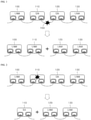
- FIGS. 1 to 4 show a concept of an operation for recovering the network when communication failure has occurred on the network in the conventional RAPIEnet system.
- FIG. 1 illustrates the network recovering operation when the cable is disconnected or removed in the RAPIEnet line network line network composed of 4 network devices.
- a cable 150 connected to and disposed between the devices in the RAPIEnet line network composed of 4 network devices 100, 110, 120, and 130 is disconnected or removed.
- two adjacent devices 110 and 120 to the cable 150 may recognize the changed state of the link. Then, the two adjacent devices 110 and 120 may broadcast to the network that they have become ends (LMN) of the network, and thus inform the devices 100 and 130 existing on the network that the network have become a new line network state.
- LDN ends
- FIG. 2 illustrates network recovering operation when a device is powered off in the RAPIEnet line network composed of 4 network devices.
- one device 110 is powered off in the RAPIEnet line network composed of four network devices network devices 100, 110, 120, and 130.
- two network devices 100 and 120 adjacent to the device 110 whose power is turned off recognize the changed state of the link.
- the two network devices 100 and 120 adjacent to the device 110 may broadcast to the network that they have become the ends (LMN) of the network, and thus inform the devices 130 existing on the network that the network have become a new line network state.
- LDN ends
- the network device 100 changes its state to SA (Stand Alone) because there are no other devices respectively connected to left and right sides of the network device 100.
- FIG. 3 illustrates network recovering operation when the cable is disconnected or removed in the RAPIEnet ring network composed of 4 network devices.
- a cable 250 connected to and disposed between devices in the RAPIEnet ring network composed of four network devices 200, 210, 220, and 230 is disconnected or removed.
- two devices 200 and 230 adjacent to the cable 250 may recognize the changed state of the link. Then, the two devices 200 and 230 may broadcast to the network that they have become ends (LNM) of the network, and thus inform the devices 210 and 220 existing on the network that the network have become a new line network state.
- LNM ends
- FIG. 4 illustrates network recovering operation when a device is powered off in the RAPIEnet ring network composed of 4 network devices.
- one device 230 is powered off in the RAPIEnet line network composed of four network devices network devices 200, 210, 220, and 230.
- two network devices 200 and 220 adjacent to the device 230 that are powered off recognize the changed state of the link. Then, the two network devices 200 and 220 may broadcast to the network that they have become ends (LNM) of the network, and thus inform the devices 210 existing on the network that the network have become a new line network state.
- LNM ends
- the conventional RAPIEnet system provides a function to automatically recover the state of the network when the state of the network has changed due to link disconnection or power failure of the device.
- the conventional network recovering method in the RAPIEnet system as described above may recover the network when the cable is disconnected or removed or the device is powered off.
- the conventional network recovering method may not recover the network when the communication failure is caused by device failure rather than by the communication failure between the devices or the power off of the device.
- a purpose of the present disclosure is to provide a network recovering method when communication failure has occurred in the RAPIEnet system, in which periodic transmission of a message to check whether network communication failure has occurred between line network manager (LNM) devices or ring network manager (RNM) devices on a ring or line-shaped network in the RAPIEnet system is performed to more accurately determine whether communication failure of the network has occurred and recover the network while not burdening the network.
- LNM line network manager
- RPM ring network manager
- a method for recovering a network when communication failure has occurred in a RAPIEnet line network composed of a plurality of network devices comprises transmitting, first and second LNM (line network manager) network devices respectively positioned at both opposing ends of the line network, a network integrity check message (NICM) to the second and first LNM network devices, respectively; when the first and/or second LNM network devices fail to receive the NICM transmitted from the second and/or first LNM network devices, respectively, instructing, by each of the first and second LNM network devices, each of all network devices on the line network route to perform communication check with a network device of a neighboring node thereto; in response to the instruction, transmitting, by each of all network devices on the line network route, a family request message to the network device of the neighboring node thereto to identify a connection state therebetween; and changing, by the network device failing to not receive a response message to the family request message, a state thereof to LNM or SA (stand alone).
- LNM line network manager
- the method may further comprise transmitting, by the network device which has received the response message to the family request message, the family request message to the network device of the neighboring node thereto to identify a connection state therebetween.
- the instructing of performing the communication check may include waiting, by the first and second LNM network devices, for the reception of the NICM transmitted from the second and first LNM network devices, respectively, for a preset time duration; and when the first and/or second LNM network devices fail to receive the NICM transmitted from the second and/or first LNM network devices, respectively, for the present time duration, broadcasting, by each of the first and second LNM network devices, a neighbor check command message (NCCM) to each of all network devices on the line network route.
- NCM neighbor check command message
- the method may further comprise broadcasting, by the network device whose state has been changed to the LNM among the network devices, a line start message for notifying that a new line network starts to the LNM network devices of the line network.
- the NICM may be repeatedly created according to a preset period and by each of the first and second LNM network devices respectively positioned at both opposing ends of the line network, and then may be transmitted to each of the second and first LNM network devices.
- the network device may be equipped with a RAPIEnet protocol and may have two communication ports to be able to transmit data in both opposite directions of the line network.
- a method for recovering a network when communication failure has occurred in a RAPIEnet ring network composed of a plurality of network devices comprises transmitting, each of first and second RNM (ring network manager) network devices on the ring network, a network integrity check message (NICM) along bidirectional routes of the ring network; when the first and/or second RNM network devices fail to receive the NICM transmitted from the second and/or first RNM network devices, respectively, instructing, by each of the first and second RNM network devices, each of all network devices on the bidirectional routes of the ring network to perform communication check with a network device of a neighboring node thereto; in response to the instruction, transmitting, by each of all network devices on the line network route, a family request message to the network device of the neighboring node thereto to identify a connection state therebetween; and changing, by the network device failing to not receive a response message to the family request message, a state thereof to LNM.
- first and second RNM ring network manager
- the method may further comprise transmitting, by the network device which has received the response message to the family request message, the family request message to the network device of the neighboring node thereto to identify a connection state therebetween.
- the instructing of performing the communication check may include waiting, by the first and second RNM network devices, for the reception of the NICM transmitted from the second and first RNM network devices, respectively, for a preset time duration; and when the first and/or second RNM network devices fail to receive the NICM transmitted from the second and/or first RNM network devices, respectively, for the present time duration, broadcasting, by each of the first and second RNM network devices, a neighbor check command message (NCCM) to each of all network devices on the bidirectional routes of the ring network.
- NCM neighbor check command message
- the method may further comprise broadcasting, by the network device whose state has been changed to the LNM, a line start message for notifying formation of a new line network to the RNM network devices.
- the NICM may be repeatedly created according to a preset period and by each of the first and second RNM network devices, and then may be transmitted to each of the second and first LNM network devices.
- the network recovering method periodically transmits the message to check whether network communication failure has occurred between line network manager (LNM) devices or ring network manager (RNM) devices on a ring or line-shaped network in the RAPIEnet system to more accurately determine whether communication failure of the network has occurred and recover the network while not burdening the network.
- LNM line network manager
- RPM ring network manager
- the network recovering method may effectively detect not only the link state change such as cable disconnection and removal but also the communication failure of the network device or the communication line failure to more accurately determine whether communication failure of the network has occurred and recover the network.
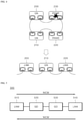
- FIG. 5 is a conceptual diagram of an operation for recovering the network when communication failure has occurred on the line network in the RAPIEnet system according to one embodiment of the present disclosure.
- FIG. 5 illustrates the network recovering operation when communication failure has occurred on the network in the RAPIEnet line network composed of four network devices 510, 520, 530, 540 according to one embodiment of the present disclosure.
- the present disclosure is not limited thereto.
- two LNM network devices 510 and 540 respectively positioned at both ends of the line network may periodically transmit a network integrity check message (NICM) to the counterpart LNM network devices 540 and 510.
- NVM network integrity check message
- the two LNM network devices 510 and 540 may periodically receive the NICM from the counterpart LNM network devices 540 and 510, and identify whether there is a problem such as communication failure in the network devices 510, 520, 530, and 540 existing on the network route.
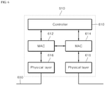
- FIG. 6 shows the internal configuration of the network device shown in FIG. 5 .
- the network device 510 may be equipped with a protocol such as RAPIEnet. Further, the network device 510 may have two communication ports and may be capable of transmitting data in both directions of the network implemented as a line network or a ring network.
- the network device 510 may be an input/output device of a PLC (programmable logic controller).
- the network device 510 may include two physical layers 616 and 618 and media access controllers (MAC) 612 and 614, and a controller 610.
- MAC media access controller
- the physical layers 616 and 618 receive data from the network bus 650 and provide the data to the media access controllers 612 and 614. Further, the physical layers 616 and 618 transmit data applied from the media access controllers 612 and 614 to the network bus 650 .
- the media access controllers 612 and 614 receive data from the controller 610.
- the media access controllers 612 and 614 transmit the data received from the controller 610 to the network bus 650 via the physical layers 616 and 618.
- the media access controllers 612 and 614 determine a type of the data received via the physical layers 616 and 618 .
- the media access controllers 612 and 614 may not transmit the data to the controller 610, but may transmit the data to the network bus 650 via the physical layers 616 and 618.
- the data may be transmitted to another network device on the network.
- the data that does not need to be transmitted to the controller 610 may be NICM.
- the NICM may refer to a message transmitted to check whether there is a problem in the network route between LNM network devices 510 and 540 or between RNM network devices 810 and 840 of the line network or ring network according to one embodiment of the present disclosure. This NICM may not pass through the controller 610 but may be transmitted to a next network device in devices other than the LNM network device, and may not burden all of the network devices.
- the media access controllers 612 and 614 determine a type of data received via the physical layers 616 and 618. When the media access controllers 612 and 614 determine that the data needs to be transmitted to the controller 610, the media access controllers 612 and 614 transmit the data to the controller 610.
- the data that needs to be transmitted to the controller 610 may be a neighbor check command message (NCCM) or a family request message.
- the NCCM or family request message may be used to detect a network device in which communication failure has occurred when the communication failure has occurred due to disconnection or removal of the cable, the power off of the device, or the device failure in the line network or ring network. In all network devices, the NCCM or family request message may be set to be transmitted to the controller 610. The controller 610 may check whether communication failure has occurred in the network device of a neighbor node, based on a response message to the family request message.
- the controller 610 performs data transmission/reception to and from the media access controllers 612 and 614.
- the controller 610 uses the transmitted and received data to determine whether communication failure has occurred on the network and whether the network device 510 having the controller 610 has become an end in the line network or the ring network.
- the controller 610 may change the state of the network device 510 to LNM or SA (Stand Alone). Then, the controller 610 transmits the changed state information to the LNM network device 540 or the RNM network device 840.
- Such state information may be converted into a line start message notifying that a new line network starts.
- the line start message may be broadcast to the network, and may be received by the LNM network device 540 or the RNM network device 840.
- FIG. 7 shows a signal processing flow between network devices for detecting a communication failure of a network device and recovering the network in a line network including a plurality of network devices of FIG. 5 according to one embodiment of the present disclosure.
- two LNM network devices 510 and 540 respectively positioned at both ends of the line network 500 transmit NICM to the counterpart LNM network devices 540 and 510 of the line network 500, respectively (S700 and S750).
- each of the LNM network devices 510 and 540 does not receive the NICM transmitted from each of the counterpart LNM network device 540 and 510, thus resulting in a time-out (S702, S752).
- each of the LNM network devices 510 and 540 may transmit NCCM to all network devices 520 and 530 on the line network in a broadcast manner to instruct each of all network devices 520 and 530 on the line network route to check communication with a network device of a neighboring node thereto (S704, S754).
- each of the network devices 520 and 530 may transmit the family request message to a network device of a neighboring node thereto, and may check whether the network device of the neighboring node operates a normally.
- the communication failure has occurred in the network device 520 on the line network.
- the LNM network device 510 at a left end of FIG. 7 does not normally receive the family response message to the family request message (S706) and thus a timeout occurs (S708).
- the LNM network device 510 may determine that a problem has occurred in the route with the network device 520 of the neighbor node thereto, the LNM network device 510 changes its state to LNM or SA (S710).
- the LNM network device 510 at the left end of FIG. 7 changes its state to SA because there are no network devices respectively connected to the left and right sides of the network device 510.
- the LNM network device 540 at the right end of FIG. 7 normally receives the family response message to the family request message S756 because the network device 530 adjacent to the LNM network device 540 normally operates (S758).
- the network device 530 transmits a family request message to the network device 520 of a neighboring node thereto (S760).
- a timeout occurs in the network device 530 (S762).
- the network device 530 in which the timeout has occurred may determine that a problem has occurred in the route with the network device 520 of the neighbor node thereto, and thus may change a state thereof to LNM or SA.
- the network device 530 is connected to the LNM network device 540 and thus changes a state thereof to the LNM (S764).
- the network device 530 whose state has changed to the LNM transmits a line start message to the LNM network device 540 to inform that a new line network starts (S766).
- FIG. 8 shows a concept of an operation for recovering the network when communication failure has occurred on the ring network in the RAPIEnet system according to one embodiment of the present disclosure.
- FIG. 8 illustrates the network recovering operation when communication failure has occurred on the network in the RAPIEnet ring network composed of four network devices 810, 820, 830, and 840 according to one embodiment of the present disclosure.
- the present disclosure is not limited thereto.
- two RNM network devices 810 and 840 on the ring network periodically transmit NICM to the counterpart two RNM network devices 840 and 810 in a bidirectional route of the ring network, respectively.
- the two RNM network devices 810 and 840 may periodically receive NICM from the counter RNM network devices 840 and 810, and may identify whether there is a problem such as communication failure in each of the network devices 810, 820, 830, and 840 existing on the network route.
- FIG. 9 shows a signal processing flow between network devices for detecting a communication failure of a network device and recovering the network in a ring network including the plurality of network devices of FIG. 8 according to one embodiment of the present disclosure.
- each of two RNM network devices 810 and 840 respectively positioned at both bidirectional route ends of the ring network 800 transmits NICM along the bidirectional route of the ring network 800 (S900, S950).
- each of the RNM network devices 810 and 840 cannot receive the NICM transmitted from each of the counterpart RNM network devices, and thus a time-out occurs (S902, S952).
- each of the RNM network devices 810 and 840 transmits NCCM, in a broadcast manner, to all network devices 820 and 830 on the ring network to instruct each of all network devices 820 and 830 on the bidirectional route of the ring network to check communication with the network device of a neighboring node thereto (S904, S954).
- FIG. 9 does not show a network device on a network 900 in the ring network. This is only for convenience of description. The present disclosure is equally applicable to the network device in the network 900.
- each of the network devices 820 and 830 Upon receiving the NCCM, each of the network devices 820 and 830 transmits a family request message to the network device of the neighboring node thereto to check whether the network device of the neighboring node normally operates.
- a left RNM network device 810 of FIG. 9 fails to receive the family response message to the family request message (S906) and thus a timeout occurs (S908).
- the RNM network device 810 may determine that there is a problem in the route with the network device 820 of the neighboring node thereto, and may change a state thereof to LNM (S910). In this connection, because the communication failure has occurred in the network device 820 and the state of the network has changed to the line network, the RNM network device 810 changes a state thereof to the LNM.
- the network device 810 whose state has changed to the LNM transmits a line start message to the RNM network device 840 via the network (reference number 900) of the ring network to inform that a new line network starts (S912).
- the RNM network device 840 at the right side of FIG. 9 normally receives the family response message to the family request message (S956) because the network device 830 adjacent to the RNM network device 840 is operating normally (S958).
- the network device 830 transmits a family request message to the network device 820 of a neighboring node thereto (S960).
- a timeout occurs in the network device 830 (S962).
- the network device 830 in which the timeout has occurred may determine that a problem has occurred in the route with the network device 820 of the neighbor node thereto, and thus may change a state thereof LNM (S964).
- the network device 830 is connected to the RNM network device 840 and changes a state thereof to LNM.
- the network device 830 whose state has changed to the LNM transmits a line start message to the LNM network device 840 to inform that a new line network starts (S966).
- the network recovering method periodically transmits the message to check whether network communication failure has occurred between line network manager (LNM) devices or ring network manager (RNM) devices on a ring or line-shaped network in the RAPIEnet system to more accurately determine whether communication failure of the network has occurred and recover the network while not burdening the network.
- LNM line network manager
- RPM ring network manager
- All methods and procedures disclosed herein may be implemented, at least in part, using one or more computer programs or components. These components may be provided as a series of computer instructions stored in any conventional computer-readable medium or machine-readable medium, including volatile and non-volatile memory such as RAM, ROM, flash memory, magnetic or optical disks, optical memory or other storage devices.
- the instructions may be provided as software or firmware, and may be implemented in whole or in part in a hardware component such as an ASIC, FPGA, DSP or other similar device.
- the instructions may be configured to be executed by one or more processors or other hardware components to perform or facilitate the performance of all or some of steps of the disclosed method and procedure.
Landscapes
- Engineering & Computer Science (AREA)
- Computer Networks & Wireless Communication (AREA)
- Signal Processing (AREA)
- Environmental & Geological Engineering (AREA)
- Health & Medical Sciences (AREA)
- Cardiology (AREA)
- General Health & Medical Sciences (AREA)
- Small-Scale Networks (AREA)
Abstract
Description
- The present disclosure relates to a RAPIEnet system. More particularly, the present disclosure relates to a network recovering method when communication failure has occurred in the RAPIEnet system, in which periodic transmission of a message to check whether network communication failure has occurred between line network manager (LNM) devices or ring network manager (RNM) devices on a ring or line-shaped network in the RAPIEnet system is performed to more accurately determine whether communication failure of the network has occurred and recover the network while not burdening the network.
- RAPIEnet stands for Real-time Automation Protocols for Industrial Ethernet. Applications thereof include automation of manufacturing processes of semiconductors and automobiles, automation of power facilities, etc. RAPIEnet may be applied to an environment which is poor in terms of temperature/chemical/noise/vibration, etc. For this reason, failures such as loss of communication function due to deterioration of the network equipment or disconnection of network cables may occur at arbitrary times.
- In preparation for the failures such as loss of communication function as described above, conventional RAPIEnet has a function to notify the failure to the network.
-
FIGS. 1 to 4 show a concept of an operation for recovering the network when communication failure has occurred on the network in the conventional RAPIEnet system. -
FIG. 1 illustrates the network recovering operation when the cable is disconnected or removed in the RAPIEnet line network line network composed of 4 network devices. - Referring to
FIG. 1 , it may be identified that acable 150 connected to and disposed between the devices in the RAPIEnet line network composed of 4network devices - In this case, in the conventional RAPIEnet system, two
adjacent devices cable 150 may recognize the changed state of the link. Then, the twoadjacent devices devices -
FIG. 2 illustrates network recovering operation when a device is powered off in the RAPIEnet line network composed of 4 network devices. - Referring to
FIG. 2 , it may be identified that onedevice 110 is powered off in the RAPIEnet line network composed of four networkdevices network devices - In this case, in the conventional RAPIEnet system, two
network devices device 110 whose power is turned off recognize the changed state of the link. In addition, the twonetwork devices device 110 may broadcast to the network that they have become the ends (LMN) of the network, and thus inform thedevices 130 existing on the network that the network have become a new line network state. - In this connection, in
FIG. 2 , thenetwork device 100 changes its state to SA (Stand Alone) because there are no other devices respectively connected to left and right sides of thenetwork device 100. -
FIG. 3 illustrates network recovering operation when the cable is disconnected or removed in the RAPIEnet ring network composed of 4 network devices. - Referring to
FIG. 3 , it may be identified that acable 250 connected to and disposed between devices in the RAPIEnet ring network composed of fournetwork devices - In this case, in the conventional RAPIEnet system, two
devices cable 250 may recognize the changed state of the link. Then, the twodevices devices -
FIG. 4 illustrates network recovering operation when a device is powered off in the RAPIEnet ring network composed of 4 network devices. - Referring to
FIG. 4 , it may be identified that onedevice 230 is powered off in the RAPIEnet line network composed of four networkdevices network devices - In this case, in the conventional RAPIEnet system, two
network devices device 230 that are powered off recognize the changed state of the link. Then, the twonetwork devices devices 210 existing on the network that the network have become a new line network state. - That is, as described in
FIGS. 1 to 4 above, the conventional RAPIEnet system provides a function to automatically recover the state of the network when the state of the network has changed due to link disconnection or power failure of the device. - The conventional network recovering method in the RAPIEnet system as described above may recover the network when the cable is disconnected or removed or the device is powered off. However, the conventional network recovering method may not recover the network when the communication failure is caused by device failure rather than by the communication failure between the devices or the power off of the device.
- A purpose of the present disclosure is to provide a network recovering method when communication failure has occurred in the RAPIEnet system, in which periodic transmission of a message to check whether network communication failure has occurred between line network manager (LNM) devices or ring network manager (RNM) devices on a ring or line-shaped network in the RAPIEnet system is performed to more accurately determine whether communication failure of the network has occurred and recover the network while not burdening the network.
- Purposes of the present disclosure are not limited to the above-mentioned purpose. Other purposes and advantages of the present disclosure that are not mentioned above may be understood based on following descriptions, and will be more clearly understood with reference to embodiments of the present disclosure. Further, it will be readily apparent that the purposes and advantages of the present disclosure may be realized using means and combinations thereof indicated in the Claims.
- A method for recovering a network when communication failure has occurred in a RAPIEnet line network composed of a plurality of network devices comprises transmitting, first and second LNM (line network manager) network devices respectively positioned at both opposing ends of the line network, a network integrity check message (NICM) to the second and first LNM network devices, respectively; when the first and/or second LNM network devices fail to receive the NICM transmitted from the second and/or first LNM network devices, respectively, instructing, by each of the first and second LNM network devices, each of all network devices on the line network route to perform communication check with a network device of a neighboring node thereto; in response to the instruction, transmitting, by each of all network devices on the line network route, a family request message to the network device of the neighboring node thereto to identify a connection state therebetween; and changing, by the network device failing to not receive a response message to the family request message, a state thereof to LNM or SA (stand alone).
- Further, the method may further comprise transmitting, by the network device which has received the response message to the family request message, the family request message to the network device of the neighboring node thereto to identify a connection state therebetween.
- Further, the instructing of performing the communication check may include waiting, by the first and second LNM network devices, for the reception of the NICM transmitted from the second and first LNM network devices, respectively, for a preset time duration; and when the first and/or second LNM network devices fail to receive the NICM transmitted from the second and/or first LNM network devices, respectively, for the present time duration, broadcasting, by each of the first and second LNM network devices, a neighbor check command message (NCCM) to each of all network devices on the line network route.
- Further, the method may further comprise broadcasting, by the network device whose state has been changed to the LNM among the network devices, a line start message for notifying that a new line network starts to the LNM network devices of the line network.
- Further, the NICM may be repeatedly created according to a preset period and by each of the first and second LNM network devices respectively positioned at both opposing ends of the line network, and then may be transmitted to each of the second and first LNM network devices.
- Further, the network device may be equipped with a RAPIEnet protocol and may have two communication ports to be able to transmit data in both opposite directions of the line network.
- Further, a method for recovering a network when communication failure has occurred in a RAPIEnet ring network composed of a plurality of network devices comprises transmitting, each of first and second RNM (ring network manager) network devices on the ring network, a network integrity check message (NICM) along bidirectional routes of the ring network; when the first and/or second RNM network devices fail to receive the NICM transmitted from the second and/or first RNM network devices, respectively, instructing, by each of the first and second RNM network devices, each of all network devices on the bidirectional routes of the ring network to perform communication check with a network device of a neighboring node thereto; in response to the instruction, transmitting, by each of all network devices on the line network route, a family request message to the network device of the neighboring node thereto to identify a connection state therebetween; and changing, by the network device failing to not receive a response message to the family request message, a state thereof to LNM.
- Further, the method may further comprise transmitting, by the network device which has received the response message to the family request message, the family request message to the network device of the neighboring node thereto to identify a connection state therebetween.
- Further, the instructing of performing the communication check may include waiting, by the first and second RNM network devices, for the reception of the NICM transmitted from the second and first RNM network devices, respectively, for a preset time duration; and when the first and/or second RNM network devices fail to receive the NICM transmitted from the second and/or first RNM network devices, respectively, for the present time duration, broadcasting, by each of the first and second RNM network devices, a neighbor check command message (NCCM) to each of all network devices on the bidirectional routes of the ring network.
- Further, the method may further comprise broadcasting, by the network device whose state has been changed to the LNM, a line start message for notifying formation of a new line network to the RNM network devices.
- Further, the NICM may be repeatedly created according to a preset period and by each of the first and second RNM network devices, and then may be transmitted to each of the second and first LNM network devices.
- According to the present disclosure, the network recovering method periodically transmits the message to check whether network communication failure has occurred between line network manager (LNM) devices or ring network manager (RNM) devices on a ring or line-shaped network in the RAPIEnet system to more accurately determine whether communication failure of the network has occurred and recover the network while not burdening the network.
- Further, according to the present disclosure, the network recovering method may effectively detect not only the link state change such as cable disconnection and removal but also the communication failure of the network device or the communication line failure to more accurately determine whether communication failure of the network has occurred and recover the network.
- The above-described effects, and specific effects of the present disclosure as not mentioned above will be described based on specific details for carrying out the disclosure.
-
-
FIGS. 1 to 4 are conceptual diagrams of an operation for recovering the network when communication failure has occurred on the network in the conventional RAPIEnet system. -
FIG. 5 is a conceptual diagram of an operation for recovering the network when communication failure has occurred on the line network in the RAPIEnet system according to one embodiment of the present disclosure. -
FIG. 6 is an internal configuration diagram of a network device shown inFIG. 5 . -
FIG. 7 is a signal processing flow diagram between network devices in a line network including a plurality of network devices according to one embodiment of the present disclosure. -
FIG. 8 is a conceptual diagram of an operation for recovering the network when communication failure has occurred on the ring network in the RAPIEnet system according to one embodiment of the present disclosure. -
FIG. 9 is a flowchart of signal processing between network devices in a ring network including a plurality of network devices according to one embodiment of the present disclosure. - The above objects, features and advantages will be described in detail later with reference to the accompanying drawings. Accordingly, a person with ordinary knowledge in the technical field to which the present disclosure belongs will be able to easily implement the technical idea of the present disclosure. In describing the present disclosure, when it is determined that a detailed description of a known component related to the present disclosure may unnecessarily obscure gist the present disclosure, the detailed description is omitted. Hereinafter, a preferred embodiment according to the present disclosure will be described in detail with reference to the accompanying drawings. In the drawings, the same reference numerals are used to indicate the same or similar elements.
-
FIG. 5 is a conceptual diagram of an operation for recovering the network when communication failure has occurred on the line network in the RAPIEnet system according to one embodiment of the present disclosure. - Further,
FIG. 5 illustrates the network recovering operation when communication failure has occurred on the network in the RAPIEnet line network composed of fournetwork devices - Referring to
FIG. 5 , in the line network according to one embodiment of the present disclosure, twoLNM network devices LNM network devices - Next, the two
LNM network devices LNM network devices network devices -
FIG. 6 shows the internal configuration of the network device shown inFIG. 5 . - The
network device 510 may be equipped with a protocol such as RAPIEnet. Further, thenetwork device 510 may have two communication ports and may be capable of transmitting data in both directions of the network implemented as a line network or a ring network. Thenetwork device 510 may be an input/output device of a PLC (programmable logic controller). - Referring to
FIG. 6 , thenetwork device 510 may include twophysical layers controller 610. - The
physical layers network bus 650 and provide the data to themedia access controllers physical layers media access controllers network bus 650 . - The
media access controllers controller 610. Themedia access controllers controller 610 to thenetwork bus 650 via thephysical layers - Further, the
media access controllers physical layers controller 610, themedia access controllers controller 610, but may transmit the data to thenetwork bus 650 via thephysical layers controller 610 may be NICM. The NICM may refer to a message transmitted to check whether there is a problem in the network route betweenLNM network devices RNM network devices controller 610 but may be transmitted to a next network device in devices other than the LNM network device, and may not burden all of the network devices. - Further, the
media access controllers physical layers media access controllers controller 610, themedia access controllers controller 610. In this connection, the data that needs to be transmitted to thecontroller 610 may be a neighbor check command message (NCCM) or a family request message. According to one embodiment of the present disclosure, the NCCM or family request message may be used to detect a network device in which communication failure has occurred when the communication failure has occurred due to disconnection or removal of the cable, the power off of the device, or the device failure in the line network or ring network. In all network devices, the NCCM or family request message may be set to be transmitted to thecontroller 610. Thecontroller 610 may check whether communication failure has occurred in the network device of a neighbor node, based on a response message to the family request message. - The
controller 610 performs data transmission/reception to and from themedia access controllers controller 610 uses the transmitted and received data to determine whether communication failure has occurred on the network and whether thenetwork device 510 having thecontroller 610 has become an end in the line network or the ring network. - In this connection, when the
controller 610 determines that thenetwork device 510 having thecontroller 610 has become the end in the line network or ring network upon the occurrence of the communication failure on the network, thecontroller 610 may change the state of thenetwork device 510 to LNM or SA (Stand Alone). Then, thecontroller 610 transmits the changed state information to theLNM network device 540 or theRNM network device 840. Such state information may be converted into a line start message notifying that a new line network starts. The line start message may be broadcast to the network, and may be received by theLNM network device 540 or theRNM network device 840. -
FIG. 7 shows a signal processing flow between network devices for detecting a communication failure of a network device and recovering the network in a line network including a plurality of network devices ofFIG. 5 according to one embodiment of the present disclosure. - Hereinafter, with reference to
FIG. 7 , one embodiment of the present disclosure will be described in more detail. - First, two
LNM network devices line network 500 transmit NICM to the counterpartLNM network devices line network 500, respectively (S700 and S750). - In this connection, as shown in
FIG. 7 , communication failure has occurred in thenetwork device 520 on the line network. Therefore, each of theLNM network devices LNM network device - Then, each of the
LNM network devices network devices network devices - Then, upon receiving the NCCM, each of the
network devices - In this connection, the communication failure has occurred in the
network device 520 on the line network. Thus, theLNM network device 510 at a left end ofFIG. 7 does not normally receive the family response message to the family request message (S706) and thus a timeout occurs (S708). - Then, the
LNM network device 510 may determine that a problem has occurred in the route with thenetwork device 520 of the neighbor node thereto, theLNM network device 510 changes its state to LNM or SA (S710). In this connection, theLNM network device 510 at the left end ofFIG. 7 changes its state to SA because there are no network devices respectively connected to the left and right sides of thenetwork device 510. - On the other hand, the
LNM network device 540 at the right end ofFIG. 7 normally receives the family response message to the family request message S756 because thenetwork device 530 adjacent to theLNM network device 540 normally operates (S758). - Then, the
network device 530 transmits a family request message to thenetwork device 520 of a neighboring node thereto (S760). In this connection, because the communication failure has occurred in thenetwork device 520, a timeout occurs in the network device 530 (S762). - Then, the
network device 530 in which the timeout has occurred may determine that a problem has occurred in the route with thenetwork device 520 of the neighbor node thereto, and thus may change a state thereof to LNM or SA. - In this connection, the
network device 530 is connected to theLNM network device 540 and thus changes a state thereof to the LNM (S764). Next, thenetwork device 530 whose state has changed to the LNM transmits a line start message to theLNM network device 540 to inform that a new line network starts (S766). -
FIG. 8 shows a concept of an operation for recovering the network when communication failure has occurred on the ring network in the RAPIEnet system according to one embodiment of the present disclosure. - Further,
FIG. 8 illustrates the network recovering operation when communication failure has occurred on the network in the RAPIEnet ring network composed of fournetwork devices - Referring to
FIG. 8 , in the ring network according to one embodiment of the present disclosure, twoRNM network devices RNM network devices - Next, the two
RNM network devices RNM network devices network devices -
FIG. 9 shows a signal processing flow between network devices for detecting a communication failure of a network device and recovering the network in a ring network including the plurality of network devices ofFIG. 8 according to one embodiment of the present disclosure. - Hereinafter, one embodiment of the present disclosure will be described in more detail with reference to
FIG. 9 . - First, each of two
RNM network devices ring network 800 transmits NICM along the bidirectional route of the ring network 800 (S900, S950). - In this connection, as shown in
FIG. 9 , communication failure has occurred in thenetwork device 820 on the ring network. Therefore, each of theRNM network devices - Then, each of the
RNM network devices network devices network devices FIG. 9 does not show a network device on anetwork 900 in the ring network. This is only for convenience of description. The present disclosure is equally applicable to the network device in thenetwork 900. - Then, Upon receiving the NCCM, each of the
network devices - In this connection, because communication failure has occurred in the
network device 820 on the ring network, a leftRNM network device 810 ofFIG. 9 fails to receive the family response message to the family request message (S906) and thus a timeout occurs (S908). - Then, the
RNM network device 810 may determine that there is a problem in the route with thenetwork device 820 of the neighboring node thereto, and may change a state thereof to LNM (S910). In this connection, because the communication failure has occurred in thenetwork device 820 and the state of the network has changed to the line network, theRNM network device 810 changes a state thereof to the LNM. - Next, the
network device 810 whose state has changed to the LNM transmits a line start message to theRNM network device 840 via the network (reference number 900) of the ring network to inform that a new line network starts (S912). - On the other hand, the
RNM network device 840 at the right side ofFIG. 9 normally receives the family response message to the family request message (S956) because thenetwork device 830 adjacent to theRNM network device 840 is operating normally (S958). - Then, the
network device 830 transmits a family request message to thenetwork device 820 of a neighboring node thereto (S960). In this connection, because the communication failure has occurred in thenetwork device 820, a timeout occurs in the network device 830 (S962). - Then, the
network device 830 in which the timeout has occurred may determine that a problem has occurred in the route with thenetwork device 820 of the neighbor node thereto, and thus may change a state thereof LNM (S964). - In this connection, the
network device 830 is connected to theRNM network device 840 and changes a state thereof to LNM. Next, thenetwork device 830 whose state has changed to the LNM transmits a line start message to theLNM network device 840 to inform that a new line network starts (S966). - As described above, according to the present disclosure, the network recovering method periodically transmits the message to check whether network communication failure has occurred between line network manager (LNM) devices or ring network manager (RNM) devices on a ring or line-shaped network in the RAPIEnet system to more accurately determine whether communication failure of the network has occurred and recover the network while not burdening the network.
- All methods and procedures disclosed herein may be implemented, at least in part, using one or more computer programs or components. These components may be provided as a series of computer instructions stored in any conventional computer-readable medium or machine-readable medium, including volatile and non-volatile memory such as RAM, ROM, flash memory, magnetic or optical disks, optical memory or other storage devices. The instructions may be provided as software or firmware, and may be implemented in whole or in part in a hardware component such as an ASIC, FPGA, DSP or other similar device. The instructions may be configured to be executed by one or more processors or other hardware components to perform or facilitate the performance of all or some of steps of the disclosed method and procedure.
- As described above, the present disclosure has been described with reference to the illustrated drawings, but the present disclosure is not limited by the embodiments and drawings disclosed in the present specification. It is obvious that various modifications may be made by those skilled in the art within the scope of the technical idea of the present disclosure. In addition, when effects according to the configuration of the present disclosure are not explicitly described in describing the embodiments of the present disclosure, it is natural that predictable effects from the configuration should also be recognized.
Claims (9)
- A method for recovering a network when communication failure has occurred in a RAPIEnet line network composed of a plurality of network devices, the method comprising:transmitting, first and second LNM (line network manager) network devices (510, 540) respectively positioned at both opposing ends of the line network, a network integrity check message (NICM) to the second and first LNM network devices (510, 540), respectively;when the first and/or second LNM network devices (510, 540) fail to receive the NICM transmitted from the second and/or first LNM network devices (510, 540), respectively, instructing, by each of the first and second LNM network devices (510, 540), each of all network devices (520, 530) on the line network route to perform communication check with a network device of a neighboring node thereto;in response to the instruction, transmitting, by each of all network devices (520, 530) on the line network route, a family request message to the network device of the neighboring node thereto to identify a connection state therebetween; andchanging, by the network device failing to not receive a response message to the family request message, a state thereof to LNM or SA (stand alone).
- The method of claim 1, wherein the instructing of performing the communication check includes:waiting, by the first and second LNM network devices (510, 540), for the reception of the NICM transmitted from the second and first LNM network devices (510, 540), respectively, for a preset time duration; andwhen the first and/or second LNM network devices (510, 540) fail to receive the NICM transmitted from the second and/or first LNM network devices (510, 540), respectively, for the present time duration, broadcasting, by each of the first and second LNM network devices (510, 540), a neighbor check command message (NCCM) to each of all network devices (520, 530) on the line network route.
- The method of claim 1, wherein the method further comprises broadcasting, by the network device whose state has been changed to the LNM among the network devices, a line start message for notifying that a new line network starts to the LNM network devices of the line network.
- The method of claim 1, wherein the NICM is repeatedly created according to a preset period and by each of the first and second LNM network devices (510, 540) respectively positioned at both opposing ends of the line network, and then is transmitted to each of the second and first LNM network devices (510, 540).
- The method of claim 1, wherein the network device is equipped with a RAPIEnet protocol and has two communication ports to be able to transmit data in both opposite directions of the line network.
- A method for recovering a network when communication failure has occurred in a RAPIEnet ring network composed of a plurality of network devices, the method comprising:transmitting, each of first and second RNM (ring network manager) network devices (810, 840) on the ring network, a network integrity check message (NICM) along bidirectional routes of the ring network;when the first and/or second RNM network devices (810, 840) fail to receive the NICM transmitted from the second and/or first RNM network devices (810, 840), respectively, instructing, by each of the first and second RNM network devices (810, 840), each of all network devices (820, 830) on the bidirectional routes of the ring network to perform communication check with a network device of a neighboring node thereto;in response to the instruction, transmitting, by each of all network devices (820, 830) on the line network route, a family request message to the network device of the neighboring node thereto to identify a connection state therebetween; andchanging, by the network device failing to not receive a response message to the family request message, a state thereof to LNM.
- The method of claim 6, wherein the instructing of performing the communication check includes:waiting, by the first and second RNM network devices (810, 840), for the reception of the NICM transmitted from the second and first RNM network devices (810, 840), respectively, for a preset time duration; andwhen the first and/or second RNM network devices (810, 840) fail to receive the NICM transmitted from the second and/or first RNM network devices (810, 840), respectively, for the present time duration, broadcasting, by each of the first and second RNM network devices (810, 840), a neighbor check command message (NCCM) to each of all network devices (820, 830) on the bidirectional routes of the ring network.
- The method of claim 6, wherein the method further comprises broadcasting, by the network device whose state has been changed to the LNM, a line start message for notifying formation of a new line network to the RNM network devices.
- The method of claim 6, wherein the NICM is repeatedly created according to a preset period and by each of the first and second RNM network devices (810, 840), and then is transmitted to each of the second and first LNM network devices (810, 840).
Applications Claiming Priority (2)
| Application Number | Priority Date | Filing Date | Title |
|---|---|---|---|
| KR1020190033535A KR102102113B1 (en) | 2019-03-25 | 2019-03-25 | METHOD FOR RESTORING NETWORK COMMUNICATION FAILURE IN RAPIEnet SYSTEM |
| PCT/KR2019/010877 WO2020197008A1 (en) | 2019-03-25 | 2019-08-27 | Method for network restoration when communication failure occurs in rapienet system |
Publications (2)
| Publication Number | Publication Date |
|---|---|
| EP3952209A1 true EP3952209A1 (en) | 2022-02-09 |
| EP3952209A4 EP3952209A4 (en) | 2022-05-04 |
Family
ID=70467314
Family Applications (1)
| Application Number | Title | Priority Date | Filing Date |
|---|---|---|---|
| EP19920769.7A Pending EP3952209A4 (en) | 2019-03-25 | 2019-08-27 | PROCEDURE FOR NETWORK RECOVERY IN THE EVENT OF A LOSS OF COMMUNICATION IN A RAPIENET SYSTEM |
Country Status (6)
| Country | Link |
|---|---|
| US (1) | US11996975B2 (en) |
| EP (1) | EP3952209A4 (en) |
| JP (1) | JP7209109B2 (en) |
| KR (1) | KR102102113B1 (en) |
| CN (1) | CN113491086B (en) |
| WO (1) | WO2020197008A1 (en) |
Families Citing this family (2)
| Publication number | Priority date | Publication date | Assignee | Title |
|---|---|---|---|---|
| CN112260897A (en) * | 2020-10-19 | 2021-01-22 | 海尔优家智能科技(北京)有限公司 | Method and device for identifying connection abnormity |
| KR102539612B1 (en) | 2021-12-24 | 2023-06-02 | 엘에스일렉트릭(주) | Communication device for RAPIEnet over IP and the system including the same |
Family Cites Families (18)
| Publication number | Priority date | Publication date | Assignee | Title |
|---|---|---|---|---|
| US7483398B1 (en) * | 2001-05-18 | 2009-01-27 | Cisco Technology, Inc. | Method and system for detecting ring link provisioning mismatch |
| US7277631B1 (en) * | 2001-07-20 | 2007-10-02 | Meriton Networks Us Inc. | Method and apparatus for processing protection switching mechanism in optical channel shared protection rings |
| CN101262401B (en) * | 2007-12-28 | 2010-12-29 | 上海自动化仪表股份有限公司 | A method for realizing network recovery in loop network |
| US7801028B2 (en) * | 2007-12-31 | 2010-09-21 | Schneider Automation Inc. | Method and apparatus for transparent auto-recovery in chain and ring networks |
| KR101299443B1 (en) * | 2009-05-15 | 2013-08-22 | 한국전자통신연구원 | Method for protection switching |
| US8228946B2 (en) | 2009-07-29 | 2012-07-24 | General Electric Company | Method for fail-safe communication |
| JP5441566B2 (en) | 2009-08-28 | 2014-03-12 | 三菱電機株式会社 | Communication terminal, communication system, and node switching method |
| JP4944986B2 (en) | 2010-10-06 | 2012-06-06 | 株式会社日立製作所 | Transmission path system and transmission path construction method |
| KR101720347B1 (en) * | 2011-01-20 | 2017-03-27 | 엘에스산전 주식회사 | Adaptive multi redundant ring topology system and Method for selecting the detour |
| US8769158B2 (en) | 2011-07-08 | 2014-07-01 | Rockwell Automation Technologies, Inc. | High availability device level ring backplane |
| JP5165093B2 (en) | 2011-08-08 | 2013-03-21 | 三菱電機株式会社 | Communication management apparatus and data communication method |
| US9979595B2 (en) * | 2012-12-18 | 2018-05-22 | Juniper Networks, Inc. | Subscriber management and network service integration for software-defined networks having centralized control |
| KR101933447B1 (en) | 2014-03-17 | 2018-12-28 | 엘에스산전 주식회사 | Monitoring device of two channels bus data in network system |
| CN105897453A (en) * | 2014-07-18 | 2016-08-24 | 现代自动车株式会社 | Method for diagnosing network and apparatus for the same |
| JP2017034463A (en) | 2015-07-31 | 2017-02-09 | 富士通株式会社 | Protection method, communication system, and end node |
| KR20180100935A (en) * | 2017-03-03 | 2018-09-12 | 엘에스산전 주식회사 | A method for switching communication line in ring network |
| KR20180103478A (en) * | 2017-03-10 | 2018-09-19 | 엘에스산전 주식회사 | Method of calculating waiting time for node response in topology adaptation network management protocol |
| KR102241687B1 (en) | 2019-04-22 | 2021-04-19 | 인제대학교 산학협력단 | Device to assist inserting of circular stapler |
-
2019
- 2019-03-25 KR KR1020190033535A patent/KR102102113B1/en active Active
- 2019-08-27 WO PCT/KR2019/010877 patent/WO2020197008A1/en not_active Ceased
- 2019-08-27 US US17/442,667 patent/US11996975B2/en active Active
- 2019-08-27 JP JP2021556892A patent/JP7209109B2/en active Active
- 2019-08-27 EP EP19920769.7A patent/EP3952209A4/en active Pending
- 2019-08-27 CN CN201980093109.5A patent/CN113491086B/en active Active
Also Published As
| Publication number | Publication date |
|---|---|
| WO2020197008A1 (en) | 2020-10-01 |
| EP3952209A4 (en) | 2022-05-04 |
| CN113491086A (en) | 2021-10-08 |
| JP7209109B2 (en) | 2023-01-19 |
| JP2022528044A (en) | 2022-06-08 |
| CN113491086B (en) | 2024-06-11 |
| US20220200842A1 (en) | 2022-06-23 |
| KR102102113B1 (en) | 2020-04-20 |
| US11996975B2 (en) | 2024-05-28 |
Similar Documents
| Publication | Publication Date | Title |
|---|---|---|
| US8711686B2 (en) | Packet transmission system and fault recovery method | |
| JP7372972B2 (en) | Reconstruction of a personal area network or system after a network or system failure | |
| WO1989011187A1 (en) | Reconfigurable local area network | |
| CN108631873B (en) | Method and device for transmitting and receiving network management information, transmitting equipment and receiving equipment | |
| EP3952209A1 (en) | Method for network restoration when communication failure occurs in rapienet system | |
| CN109361597B (en) | A multi-routing method and device | |
| CN102710438B (en) | Node management method, device and system | |
| US9871616B2 (en) | Error detection and recovery in a DMX512 network | |
| CN105591817A (en) | Negotiation mode processing method and intelligent network device | |
| WO2017000096A1 (en) | Link recovery method and network device | |
| JP4102060B2 (en) | Data receiver | |
| JP3789295B2 (en) | Message transmission method and apparatus | |
| JP2009296293A (en) | Communication apparatus | |
| EP4459939B1 (en) | Channel resource adjustment method and apparatus, and communication device | |
| JPS58170247A (en) | Automatic loop back controlling system | |
| JP2003273781A (en) | Duplex communication control method | |
| JPH10303914A (en) | Protocol state synchronization system | |
| JP3679066B2 (en) | Line information table generation method | |
| CN105763246B (en) | Pretection switch method, system and node | |
| CN106936679B (en) | A kind of method and apparatus of loop network fault recovery | |
| CN108933696A (en) | OAM allocation machinery of consultation, device, management entity and storage medium | |
| JP2000316017A (en) | Optical double loop network system | |
| JPH06120964A (en) | Ring transmission device and ring transmission line failure point detection method | |
| JPH0669910A (en) | Path changeover control system | |
| JPH04108225A (en) | Redundant changeover system for two-way changeover type redundancy system for transmission line |
Legal Events
| Date | Code | Title | Description |
|---|---|---|---|
| STAA | Information on the status of an ep patent application or granted ep patent |
Free format text: STATUS: THE INTERNATIONAL PUBLICATION HAS BEEN MADE |
|
| PUAI | Public reference made under article 153(3) epc to a published international application that has entered the european phase |
Free format text: ORIGINAL CODE: 0009012 |
|
| STAA | Information on the status of an ep patent application or granted ep patent |
Free format text: STATUS: REQUEST FOR EXAMINATION WAS MADE |
|
| 17P | Request for examination filed |
Effective date: 20211019 |
|
| AK | Designated contracting states |
Kind code of ref document: A1 Designated state(s): AL AT BE BG CH CY CZ DE DK EE ES FI FR GB GR HR HU IE IS IT LI LT LU LV MC MK MT NL NO PL PT RO RS SE SI SK SM TR |
|
| REG | Reference to a national code |
Ref country code: DE Ref legal event code: R079 Free format text: PREVIOUS MAIN CLASS: H04L0012240000 Ipc: H04L0041065900 |
|
| A4 | Supplementary search report drawn up and despatched |
Effective date: 20220404 |
|
| RIC1 | Information provided on ipc code assigned before grant |
Ipc: H04L 43/10 20220101ALI20220329BHEP Ipc: H04L 43/0805 20220101ALI20220329BHEP Ipc: H04L 41/0659 20220101AFI20220329BHEP |
|
| DAV | Request for validation of the european patent (deleted) | ||
| DAX | Request for extension of the european patent (deleted) | ||
| STAA | Information on the status of an ep patent application or granted ep patent |
Free format text: STATUS: EXAMINATION IS IN PROGRESS |
|
| 17Q | First examination report despatched |
Effective date: 20231204 |