EP3952087A1 - Safety shutdown apparatus with self-driven control, power supply system, and method of controlling the same - Google Patents
Safety shutdown apparatus with self-driven control, power supply system, and method of controlling the same Download PDFInfo
- Publication number
- EP3952087A1 EP3952087A1 EP21177486.4A EP21177486A EP3952087A1 EP 3952087 A1 EP3952087 A1 EP 3952087A1 EP 21177486 A EP21177486 A EP 21177486A EP 3952087 A1 EP3952087 A1 EP 3952087A1
- Authority
- EP
- European Patent Office
- Prior art keywords
- voltage
- coupled
- power
- switch
- controllable switch
- Prior art date
- Legal status (The legal status is an assumption and is not a legal conclusion. Google has not performed a legal analysis and makes no representation as to the accuracy of the status listed.)
- Pending
Links
- 238000000034 method Methods 0.000 title claims description 10
- 238000001514 detection method Methods 0.000 claims abstract description 64
- 238000012790 confirmation Methods 0.000 claims description 26
- 230000033228 biological regulation Effects 0.000 claims description 22
- 238000010586 diagram Methods 0.000 description 26
- 230000009471 action Effects 0.000 description 9
- 230000005540 biological transmission Effects 0.000 description 3
- 238000004891 communication Methods 0.000 description 2
- 230000008878 coupling Effects 0.000 description 2
- 238000010168 coupling process Methods 0.000 description 2
- 238000005859 coupling reaction Methods 0.000 description 2
- 239000004065 semiconductor Substances 0.000 description 2
- 230000004913 activation Effects 0.000 description 1
- 239000003990 capacitor Substances 0.000 description 1
- 230000015556 catabolic process Effects 0.000 description 1
- 230000000694 effects Effects 0.000 description 1
- 230000005611 electricity Effects 0.000 description 1
- 230000005669 field effect Effects 0.000 description 1
- 229910044991 metal oxide Inorganic materials 0.000 description 1
- 150000004706 metal oxides Chemical class 0.000 description 1
- 230000008439 repair process Effects 0.000 description 1
- 230000001629 suppression Effects 0.000 description 1
- 230000001052 transient effect Effects 0.000 description 1
Images






Classifications
-
- H—ELECTRICITY
- H02—GENERATION; CONVERSION OR DISTRIBUTION OF ELECTRIC POWER
- H02H—EMERGENCY PROTECTIVE CIRCUIT ARRANGEMENTS
- H02H3/00—Emergency protective circuit arrangements for automatic disconnection directly responsive to an undesired change from normal electric working condition with or without subsequent reconnection ; integrated protection
- H02H3/12—Emergency protective circuit arrangements for automatic disconnection directly responsive to an undesired change from normal electric working condition with or without subsequent reconnection ; integrated protection responsive to underload or no-load
-
- H—ELECTRICITY
- H02—GENERATION; CONVERSION OR DISTRIBUTION OF ELECTRIC POWER
- H02H—EMERGENCY PROTECTIVE CIRCUIT ARRANGEMENTS
- H02H7/00—Emergency protective circuit arrangements specially adapted for specific types of electric machines or apparatus or for sectionalised protection of cable or line systems, and effecting automatic switching in the event of an undesired change from normal working conditions
- H02H7/10—Emergency protective circuit arrangements specially adapted for specific types of electric machines or apparatus or for sectionalised protection of cable or line systems, and effecting automatic switching in the event of an undesired change from normal working conditions for converters; for rectifiers
- H02H7/12—Emergency protective circuit arrangements specially adapted for specific types of electric machines or apparatus or for sectionalised protection of cable or line systems, and effecting automatic switching in the event of an undesired change from normal working conditions for converters; for rectifiers for static converters or rectifiers
- H02H7/1213—Emergency protective circuit arrangements specially adapted for specific types of electric machines or apparatus or for sectionalised protection of cable or line systems, and effecting automatic switching in the event of an undesired change from normal working conditions for converters; for rectifiers for static converters or rectifiers for DC-DC converters
-
- H—ELECTRICITY
- H02—GENERATION; CONVERSION OR DISTRIBUTION OF ELECTRIC POWER
- H02H—EMERGENCY PROTECTIVE CIRCUIT ARRANGEMENTS
- H02H3/00—Emergency protective circuit arrangements for automatic disconnection directly responsive to an undesired change from normal electric working condition with or without subsequent reconnection ; integrated protection
- H02H3/02—Details
- H02H3/021—Details concerning the disconnection itself, e.g. at a particular instant, particularly at zero value of current, disconnection in a predetermined order
- H02H3/023—Details concerning the disconnection itself, e.g. at a particular instant, particularly at zero value of current, disconnection in a predetermined order by short-circuiting
-
- H—ELECTRICITY
- H02—GENERATION; CONVERSION OR DISTRIBUTION OF ELECTRIC POWER
- H02H—EMERGENCY PROTECTIVE CIRCUIT ARRANGEMENTS
- H02H3/00—Emergency protective circuit arrangements for automatic disconnection directly responsive to an undesired change from normal electric working condition with or without subsequent reconnection ; integrated protection
- H02H3/08—Emergency protective circuit arrangements for automatic disconnection directly responsive to an undesired change from normal electric working condition with or without subsequent reconnection ; integrated protection responsive to excess current
Definitions
- the present disclosure relates to a safety shutdown apparatus with self-driven control, a power supply system, and a method of controlling the same.
- a shutdown apparatus 4 is usually installed between a power supply apparatus 2 and a load 3 for safety considerations when the conventional power supply apparatus supplies power to the load 3 so as to avoid that there is still electricity on transmission lines between the power supply apparatus 2 and the load 3 once the load 3 occurs unexpected problems.
- the conventional shutdown apparatus 4 may operate in the following manners. 1. Both the load 3 and the shutdown apparatus 4 need additional communication units 5, and the communication units 5 are coupled and communicate to each other by a signal line L so that the shutdown apparatus 4 is provided to connect or disconnect the power supply apparatus 2 with the load 3. 2.
- the shutdown apparatus 4 is a manual switch, and the operator manipulates the shutdown apparatus 4 according to the condition of the load 3.
- the present disclosure provides a safety shutdown apparatus with self-driven control.
- the safety shutdown apparatus with self-driven control is coupled to a power-supplying path between a power supply apparatus and a load.
- the safety shutdown apparatus includes a detection unit, a controllable switch, and a drive circuit.
- the detection unit is coupled to the power-supplying path, and generates a current confirmation signal according to a current flowing through the power-supplying path.
- the controllable switch is coupled between a positive node and a negative node of the power-supplying path, and provides a short-circuit path passing through the positive node, the controllable switch, and the negative node.
- the drive circuit is coupled to the detection unit, the power-supplying path, and the controllable switch, and receives an output voltage provided from the power supply apparatus to turn on the controllable switch, and turns off the controllable switch according to the current confirmation signal.
- the present disclosure provides a power supply system.
- the power supply system includes a plurality of power supplies, and each power supply is coupled to a load through a safety shutdown apparatus.
- the present disclosure provides a power supply system.
- the power supply system includes a plurality of power supplies, and each power supply includes a plurality of power supply units with outputs connected in series, and each power supply is coupled to a load through a safety shutdown apparatus.
- the present disclosure provides a method of controlling a safety shutdown apparatus.
- the method includes steps of: (a) detecting whether a current flowing through a power-supplying path between a power supply apparatus and a load, (b) turning off a controllable switch coupled between a positive node and a negative node of the power-supplying path when the current flowing through the power-supplying path is detected, and (c) turning on the controllable switch when the current is not detected.
- the safety shutdown apparatus is self-driven to provide the short-circuit path and operates in a safe operation mode when the power supply apparatus outputs voltage but the load does not draw current so that the output voltage of the power supply apparatus can be maintained at a low voltage. Also, the safety shutdown apparatus is self-driven to disconnect the short-circuit path and operates in a normal operation mode when the power supply apparatus outputs voltage and the load draws current.
- FIG. 2 shows a block circuit diagram of a safety shutdown apparatus with self-driven control according to the present disclosure.
- the safety shutdown apparatus 1 is coupled to a power-supplying path L1 between a power supply apparatus 2 and a load 3. According to operation conditions of the power supply apparatus 2 and the load 3, the safety shutdown apparatus 1 operates in a safe operation mode or a normal operation mode.
- the power supply apparatus 2 may be, for example but not limited to, a power supply or a solar panel with a plurality of photovoltaic cells.
- the safety shutdown apparatus 1 includes a detection unit 10, a controllable switch 12, and a drive circuit 14.
- the detection unit 10 is coupled to the power-supplying path L1.
- the detection unit 10 may be, for example but not limited to, a Hall sensor, current transformer, a current shunt for detecting a current flowing through the power-supplying path L1.
- the controllable switch 12 is coupled between a positive node A and a negative node G of the power-supplying path L1, and a short-circuit path L2 is provided passing through the positive node A, the controllable switch 12, and the negative node G.
- the positive node A here refers to any node on a positive-voltage transmission line of the power supply apparatus 2
- the negative node G here refers to any node on a negative-voltage transmission line of the power supply apparatus 2.
- the positive node A and the negative node G are preferably closer to the power supply apparatus 2.
- the drive circuit 14 is coupled to the detection unit 10, the power-supplying path L1, and the controllable switch 12, and the short-circuit path L2 is connected or disconnected according to whether a current I flowing through the power-supplying path L1 is detected by the detection unit 10 or not.
- the safety shutdown apparatus 1 is provided to turn on the controllable switch 12 to operate in the safe operation mode when the power supply apparatus 2 provides an output voltage Vo but the load 3 does not draw current (for example, out of order or under repair) so that the output voltage Vo can be maintained at a low voltage, for example but not limited to 1 volt.
- the output voltage Vo is substantially equal to a voltage VC across two ends of the controllable switch 12.
- the drive circuit 14 is coupled to the power-supplying path L1, and receives an output voltage Vo provided from the power supply apparatus 2 to turn on the controllable switch 12.
- the detection unit 10 does not detect the current I flowing through the power-supplying path L1, the detection unit 10 does not output any signal or outputs a no-load signal S2.
- a pull-down resistor may be used to output a signal with a low level as the no-load signal S2. Therefore, the drive circuit 14 is unaffected and the controllable switch 12 is still turned on. At this condition, the power supply apparatus 2, the positive node A, the controllable switch 12, and the negative node G form a closed loop. The output voltage Vo of the power supply apparatus 2 is pulled to be substantially equal to the voltage Vc across two ends of the controllable switch 12.
- the load 3 still can draw current to generate the current I.
- the detection unit 10 detects the current I flowing through the power-supplying path L1
- the detection unit 10 generates a current confirmation signal S1 according to the current I, such as a voltage signal with a high level
- the drive circuit 14 turns off the controllable switch 12 according to the current confirmation signal S1 so that the short-circuit path L2 is disconnected.
- the output voltage Vo of the power supply apparatus 2 is provided to the load 3 so that the safety shutdown apparatus 1 operates in the normal operation mode.
- the safety shutdown apparatus 1 further includes a path switch 16, and the path switch 16 is coupled to the power-supplying path L1 and its coupling position is not limited.
- the path switch 16 is an optional safety component for connecting or disconnecting the power supply apparatus 2 with the load 3.
- the path switch 16 for example but not limited to a relay, a tactile switch, a knife switch, and so forth, can be directly or indirectly manipulated to be turned on or turned off.
- FIG. 3 shows a block circuit diagram of the safety shutdown apparatus with self-driven control according to a first embodiment of the present disclosure, and also refer to FIG. 2 .
- the drive circuit 14 includes a first switch 142 and a regulation circuit 144.
- the first switch 142 is coupled to the detection unit 10 and the regulation circuit 144, and the regulation circuit 144 is coupled to the controllable switch 12 and the power-supplying path L1.
- the first switch 142 is turned on according to the current confirmation signal S1 so that the regulation circuit 144 generates the first voltage V1 or the second voltage V2 according to the state of the first switch 142. Therefore, the first voltage V1 and the second voltage V2 are provided to turn on or turn off the controllable switch 12, thereby connecting or disconnecting the short-circuit path L2.
- the first switch 142 may be, for example but not limited to, a semiconductor switch component, such as a bipolar junction transistor (BJT) or a metal-oxide semiconductor field-effect transistor (MOSFET).
- the regulation circuit 144 includes a first resistor R1 and a regulation unit ZD. One end of the first resistor R1 is coupled to one end of the regulation unit ZD, the first switch 142, and the controllable switch 12.
- the regulation unit ZD may be, for example but not limited to, a regulation component, such as a transient voltage suppression (TVS) diode or a Zener diode.
- TVS transient voltage suppression
- Zener diode a Zener diode
- the controllable switch 12 may be, for example but not limited to, a switch component, such as a BJT, a MOSFET, or a relay, also further includes other electronic components, such as a resistor, a capacitor, or a diode.
- a switch component such as a BJT, a MOSFET, or a relay
- other electronic components such as a resistor, a capacitor, or a diode.
- the detection unit 10 In the normal operation mode, as shown in FIG. 3 , when the detection unit 10 does not detect the current I, the detection unit 10 outputs the no-load signal S2 to turn off the first switch 142 since the load 3 has stopped drawing current. At this condition, the output voltage Vo of the power supply apparatus 2 results in a second voltage V2 at a node between the first resistor R1 and the regulation unit ZD.
- the second voltage V2 is a reverse breakdown voltage of the regulation unit ZD.
- the second voltage V2 drives the controllable switch 12 to be turned on so that the short-circuit path L2 is connected.
- the controllable switch 12 When the controllable switch 12 is turned on, the power supply apparatus 2, the positive node A, the controllable switch 12, and the negative node G form a closed loop so that the output voltage Vo of the power supply apparatus 2 is pulled to be substantially equal to the voltage Vc across two ends of the controllable switch 12. At this condition, the controllable switch 12 keeps turning on. In this embodiment, since the controllable switch 12 is the MOSFET, a voltage Vc across two ends of the controllable switch 12 is the drain-source voltage Vds of the MOSFET which is turned on. When the load 3 stops drawing current, the safety shutdown apparatus 1 operates from the normal operation mode to the safe operation mode so that the output voltage Vo of the power supply apparatus 2 can be maintained at a low voltage, such as 1 volt.
- the detection unit 10 detects the current I and provides the current confirmation signal S1 to the first switch 142, that is, the load 3 draws current
- the first switch 142 is turned on by the current confirmation signal S1 so that the node between the first resistor R1 and the regulation unit ZD is connected to the negative node G and a first voltage V1 is generated at the node between the first resistor R1 and the regulation unit ZD, and the first voltage V1 drives the controllable switch 12 to be turned off so that the short-circuit path L2 is disconnected.
- the output voltage Vo of the power supply apparatus 2 is provided to the load 3.
- FIG. 4A through FIG. 4D show block circuit diagrams of operating the safety shutdown apparatus according to the first embodiment of the present disclosure, and also refer to FIG. 3 .
- the controllable switch 12 shown in FIG. 4A through FIG. 4D takes an enhancement-type MOSFET as an example. If the controllable switch 12 takes a depletion-type MOSFET as an example, the operation principle is similar except that it is originally turned on.
- FIG. 4A if the output voltage Vo of the power supply apparatus 2 is zero volt, the components inside the safety shutdown apparatus 1 do not work (are not in operation), and therefore these components are represented by dashed lines.
- FIG. 4B the components in operation are represented by solid lines and the components not in operation are represented by dashed lines.
- the controllable switch 12 is turned on by the second voltage V2 at the node between the first resistor R1 and the regulation unit ZD so that the controllable switch 12 works in a linear region. Since the controllable switch 12 is turned on, the output voltage Vo of the power supply apparatus 2 is pulled to be substantially equal to the voltage Vc, for example but not limited to 1 volt, across two ends of the controllable switch 12.
- the voltage Vc can supply the detection unit 10 to make the detection unit 10 operate. Accordingly, the components inside the safety shutdown apparatus 1 can be self-driven without external signals or external power supply so that the safety shutdown apparatus 1 can operate in the safe operation mode or the normal operation mode. As long as the load 3 does not draw current, the safety shutdown apparatus 1 operates in the safe operation mode automatically.
- the components in operation are represented by solid lines and the components not in operation are represented by dashed lines.
- the voltage Vc can provide the voltage for the load 3 although the voltage Vc is not high.
- the detection unit 10 detects the current I and generates the current confirmation signal S1 to drive the first switch 142 to be turned on.
- the components in operation are represented by solid lines and the components not in operation are represented by dashed lines.
- the controllable switch 12 Since the first switch 142 is turned on, the controllable switch 12 is turned off by the first voltage V1 at the node between the first resistor R1 and the regulation unit ZD so that the controllable switch 12 is in an open-circuit condition. At this condition, the output voltage Vo is restored to 10 volts.
- the resistance of the first resistor R1 may be designed to a high resistance so that most of the current will flow through the load 3.
- FIG. 5 shows a block circuit diagram of the safety shutdown apparatus with self-driven control according to a second embodiment of the present disclosure, and also refer to FIG. 1 through FIG. 4D .
- the drive circuit 14' of the safety shutdown apparatus 1' includes a comparison unit 146 having a first input end A1, a second input end A2, and an output end O.
- the first input end A1 receives a reference voltage Vref
- the second input end A2 is coupled to the detection unit 10
- the output end O is coupled to the controllable switch 12.
- the reference voltage Vref may be acquired by dividing the output voltage Vo of the power supply apparatus 2 through a voltage divider circuit.
- the comparison unit 146 compares the signal outputted from the detection unit 10 with the reference voltage Vref, and the controllable switch 12 is turned on or turned off according to the comparison result, thereby connecting or disconnecting the short-circuit path L2.
- the drive circuit 14' further includes a clamping circuit 148.
- the clamping circuit 148 is coupled to the drive circuit 14', the controllable switch 12, and the power-supplying path L1.
- the clamping circuit 148 makes the power-supplying path L1 connect or provides a clamping voltage Vcl to the short-circuit path L2 according to whether the detection unit 10 detects the current I.
- the clamping circuit 148 provides the clamping voltage Vcl to the short-circuit path L2 so that a total voltage of the voltage Vc across the controllable switch 12 plus the clamping voltage Vcl is sufficient to drive the comparison unit 146 (or the detection unit 10).
- the clamping circuit 148 is also used to limit the current flowing through the short-circuit path L2 to avoid excessive current flowing through the controllable switch 12.
- the clamping circuit 148 makes the power-supplying path L1 connect without providing the clamping voltage Vcl.
- the clamping circuit 148 includes a voltage divider circuit Cvd, a second switch Q, and a second resistor R2.
- the voltage divider circuit Cvd includes a first voltage-dividing resistor Rd1 and a second voltage-dividing resistor Rd2 connected in series.
- the first voltage-dividing resistor Rd1 is coupled to a node B on the power-supplying path L1, and the node B is between the positive node A and the power supply apparatus 2;
- the second voltage-dividing resistor Rd2 is coupled to the drive circuit 14' and the controllable switch 12.
- the second switch Q has a first end X, a second end Y, and a control end Z.
- the first end X is coupled to the node B
- the second end Y is coupled to the positive node A
- the control end Z is coupled to the first voltage-dividing resistor Rd1 and the second voltage-dividing resistor Rd2.
- One end of the second resistor R2 is coupled to the first end X
- the other end of the second resistor R2 is coupled to the second end Y.
- the action of the second switch Q is opposite to that of the controllable switch 12, that is, when the controllable switch 12 is turned on, the second switch Q is turned off, and vice-versa.
- the comparison unit 146 compares the no-load signal S2 with the reference voltage Vref to generate the second voltage V2.
- the controllable switch 12 is driven by the second voltage V2 to be turned on.
- the comparison unit 146 compares the current confirmation signal S1 with the reference voltage Vref to generate the first voltage V1.
- the controllable switch 12 is driven by the first voltage V1 to be turned off.
- the second switch Q As shown in FIG. 5 , take the second switch Q as a P-type MOSFET as an example.
- the drive circuit 14' provides the second voltage V2
- a smaller voltage is generated between the first end X and the control end Z so that the second switch Q is turned off.
- the short-circuit path L2 passes through the second resistor R2 to generate the clamping voltage Vcl on the second resistor R2, and the second resistor R2 provides the resistance to the short-circuit path L2 to limit the current flowing through the controllable switch 12.
- a total voltage of the clamping voltage Vcl plus the voltage Vc across the controllable switch 12 is provided to the comparison unit 146 so that the output voltage Vo, the clamping voltage Vcl plus the voltage Vc, is easier to drive the comparison unit 146 when the controllable switch 12 is turned on (short-circuit).
- the drive circuit 14' provides the first voltage V1
- a greater voltage is generated between the first end X and the control end Z so that the second switch Q is turned on.
- the power-supplying path L1 passes through the second switch Q so that the second resistor R2 is bypassed without providing the clamping voltage Vcl, thereby reducing the resistance loss of the power-supplying path L1.
- clamping circuit 148 in this embodiment is also applicable to the safety shutdown apparatus 1 shown in FIG. 3 to increase self-driven voltage (for driving the detection unit 10 and the comparison unit 146) and provide the current-limiting function.
- FIG. 6A through FIG. 6C show block circuit diagrams of operating the safety shutdown apparatus according to the second embodiment of the present disclosure.
- the output voltage Vo of the power supply apparatus 2 is zero volt
- the components inside the safety shutdown apparatus 1' do not work (are not in operation), and therefore these components are represented by dashed lines.
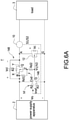
- the components in operation are represented by solid lines and the components not in operation are represented by dashed lines.
- the detection unit 10 outputs the no-load signal S2 with a low level. Since the reference voltage Vref is greater than the no-load signal S2, the comparison unit 146 provides the second voltage V2.
- the comparison unit 146 can be directly supplied power by the output voltage Vo or by a regulation circuit, such as a linear regulator or a step-down module. Therefore, the comparison unit 146 outputs the second voltage V2 according to the received output voltage Vo to turn on the controllable switch 12 and turn off the second switch Q.
- the node B, the second resistor R2, the positive node A, the controllable switch 12, and the negative node G form a loop so that the positive node A can provide a voltage for the load 3 to draw current when the second switch Q is turned off.
- the resistance of the second resistor R2 can be large to ensure that the output voltage Vo is sufficient to drive the comparison unit 146.
- the components in operation are represented by solid lines and the components not in operation are represented by dashed lines.
- the detection unit 10 Since the load 3 draws current, the detection unit 10 outputs the current confirmation signal S1. Since the current confirmation signal S1 is greater than the reference voltage Vref, the comparison unit 146 provides the first voltage V1 to turn off the controllable switch 12. In addition, the output voltage Vo is divided by the first voltage-dividing resistor Rd1 and the second voltage-dividing resistor Rd2 to turn on the second switch Q to complete the activation (startup).
- FIG. 7A to FIG. 7C show circuit diagrams of three embodiments of the detection unit of the present disclosure, and also refer to FIG. 2 through FIG. 6C .
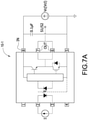
- the detection unit 10-1 is a Hall sensor, and a power input terminal IN of the Hall sensor receives a work voltage for the current detection.
- the signal output ends OUT of the Hall sensor provide the result of current detection, i.e., the current confirmation signal S1 or the no-load signal S2.
- the power input terminal IN which is coupled between two ends of the controllable switch 12 or between the node B and the negative node G, receives the output voltage Vo so that the detection unit 10-1 can be driven by the voltage Vc across the controllable switch 12 or by the total voltage of the voltage Vc across the controllable switch 12 plus the clamping voltage Vcl when the controllable switch 12 is turned on.
- the controllable switch 12 is turned off, the output voltage Vo is supplied to the load 3 and the detection unit 10-1.
- the Hall sensor When the Hall sensor is driven and the current I flows through the Hall sensor, the Hall sensor provides the current confirmation signal S1 corresponding to the magnitude of the current I to the drive circuit 14, and otherwise the no-load signal S2 is provided by using a pull-down resistor to output the no-load signal S2 with a low level.
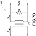
- the detection unit 10-2 is a through-type current transformer or a Rogowski coil. Since the detection unit 10-2 is the through-type current transformer, the detection unit 10-2 is not driven by a voltage. When a current I flows through the detection unit 10-2, an induced current Ii is induced. A voltage generated by the induced current Ii flowing through a resistor R is used as the current confirmation signal S1, and the current confirmation signal S1 is provided to the drive circuit 14, and otherwise the no-load signal S2 is provided.
- the detection unit 10-3 includes a sense resistor Rs and a comparison circuit 102, and the sense resistor Rs is coupled to the power-supplying path L1.
- the comparison circuit 102 has a first input end A1, a second input end A2, and an output end O.
- the first input end A1 and the second input end A2 are respectively coupled to two ends of the sense resistor and the output end O is coupled to the drive circuit 14.
- a voltage Vrs across two ends of the sense resistor Rs is zero volt so that the comparison circuit 102 outputs the no-load signal S2 with a low level.
- the voltage Vrs makes the comparison circuit 102 output the current confirmation signal S1.
- the comparison circuit 102 can be also driven by the voltage Vc across the controllable switch 12 or by the total voltage of the voltage Vc across the controllable switch 12 plus the clamping voltage Vcl.
- FIG. 8 shows a block circuit diagram of the safety shutdown apparatus with self-driven control according to a third embodiment of the present disclosure, and also refer to FIG. 2 through FIG. 7C .
- the safety shutdown apparatus 1 further includes a diode D, and the diode D is coupled between the positive node A and the negative node G.
- the diode D When the short-circuit path L2 is connected, the diode D is forward biased in a direction from the positive node A to the negative node G, and a forward voltage Vf across the diode D is produced.
- the diode D is used to increase a voltage from the positive node A to the negative node G if the voltage Vc is insufficient to drive the detection unit 10, the comparison unit 146, and/or the comparison circuit 102 when the controllable switch 12 is turned on.
- the output voltage Vo of the power supply apparatus 2 is increased to the sum of the voltage Vc and the forward voltage Vf. Therefore, the selection of components such as the detection unit 10, the comparison unit 146, and/or the comparison circuit is easier.
- FIG. 9A to FIG. 9C show block diagrams of a power supply system having a plurality of safety shutdown apparatuses according to different embodiments of the present disclosure.
- the power supply apparatus 2 which is coupled to the load 3, has multiple power supplies 22 connected in series, and each of the power supplies 22 is coupled to one safety shutdown apparatus 1. When the load 3 does not draw current, each power supply 22 can operate in the safe operation mode.
- FIG. 9B multiple power supply apparatuses 2 are provided, and the internal configuration of each power supply apparatus 2 is the same as that shown in FIG. 9A .
- FIG. 9C the power supply apparatus 2 is also provided.
- the difference between the FIG. 9C and the FIG. 9A is that the power supply apparatus 2 has multiple power supplies 22 and each power supply 22 has multiple power supply units 20.
- two power supply units 20 jointly use one safety shutdown apparatus 1 so as to save the number of components and reduce the circuit cost and volume.
Landscapes
- Engineering & Computer Science (AREA)
- Power Engineering (AREA)
- Emergency Protection Circuit Devices (AREA)
- Direct Current Feeding And Distribution (AREA)
- Protection Of Static Devices (AREA)
- Electric Propulsion And Braking For Vehicles (AREA)
- Charge And Discharge Circuits For Batteries Or The Like (AREA)
- Safety Devices In Control Systems (AREA)
Abstract
Description
- The present disclosure relates to a safety shutdown apparatus with self-driven control, a power supply system, and a method of controlling the same.
- The statements in this section merely provide background information related to the present disclosure and do not necessarily constitute prior art.
- As shown in
FIG. 1 , ashutdown apparatus 4 is usually installed between apower supply apparatus 2 and aload 3 for safety considerations when the conventional power supply apparatus supplies power to theload 3 so as to avoid that there is still electricity on transmission lines between thepower supply apparatus 2 and theload 3 once theload 3 occurs unexpected problems. Theconventional shutdown apparatus 4 may operate in the following manners. 1. Both theload 3 and theshutdown apparatus 4 needadditional communication units 5, and thecommunication units 5 are coupled and communicate to each other by a signal line L so that theshutdown apparatus 4 is provided to connect or disconnect thepower supply apparatus 2 with theload 3. 2. Theshutdown apparatus 4 is a manual switch, and the operator manipulates theshutdown apparatus 4 according to the condition of theload 3. - No matter which manner is used, the costs of the power supply system, including labor cost, circuit cost, and so forth are significantly increased. Therefore, how to design a safety shutdown apparatus with self-driven control, a power supply system, and a method of controlling the same to operate in a safe operation mode or a normal operation mode is a major issue that the inventors of the present disclosure want to overcome and solve.
- In order to solve the above-mentioned problems, the present disclosure provides a safety shutdown apparatus with self-driven control. The safety shutdown apparatus with self-driven control is coupled to a power-supplying path between a power supply apparatus and a load. The safety shutdown apparatus includes a detection unit, a controllable switch, and a drive circuit. The detection unit is coupled to the power-supplying path, and generates a current confirmation signal according to a current flowing through the power-supplying path. The controllable switch is coupled between a positive node and a negative node of the power-supplying path, and provides a short-circuit path passing through the positive node, the controllable switch, and the negative node. The drive circuit is coupled to the detection unit, the power-supplying path, and the controllable switch, and receives an output voltage provided from the power supply apparatus to turn on the controllable switch, and turns off the controllable switch according to the current confirmation signal.
- In order to solve the above-mentioned problems, the present disclosure provides a power supply system. The power supply system includes a plurality of power supplies, and each power supply is coupled to a load through a safety shutdown apparatus.
- In order to solve the above-mentioned problems, the present disclosure provides a power supply system. The power supply system includes a plurality of power supplies, and each power supply includes a plurality of power supply units with outputs connected in series, and each power supply is coupled to a load through a safety shutdown apparatus.
- In order to solve the above-mentioned problems, the present disclosure provides a method of controlling a safety shutdown apparatus. The method includes steps of: (a) detecting whether a current flowing through a power-supplying path between a power supply apparatus and a load, (b) turning off a controllable switch coupled between a positive node and a negative node of the power-supplying path when the current flowing through the power-supplying path is detected, and (c) turning on the controllable switch when the current is not detected.
- The main purpose and effect of the present disclosure are that the safety shutdown apparatus is self-driven to provide the short-circuit path and operates in a safe operation mode when the power supply apparatus outputs voltage but the load does not draw current so that the output voltage of the power supply apparatus can be maintained at a low voltage. Also, the safety shutdown apparatus is self-driven to disconnect the short-circuit path and operates in a normal operation mode when the power supply apparatus outputs voltage and the load draws current.
- It is to be understood that both the foregoing general description and the following detailed description are exemplary, and are intended to provide further explanation of the present disclosure as claimed. Other advantages and features of the present disclosure will be apparent from the following description, drawings and claims.
- The present disclosure can be more fully understood by reading the following detailed description of the embodiment, with reference made to the accompanying drawing as follows:
-
FIG. 1 is a block diagram of a conventional power supply system. -
FIG. 2 is a block circuit diagram of a safety shutdown apparatus with self-driven control according to the present disclosure. -
FIG. 3 is a block circuit diagram of the safety shutdown apparatus with self-driven control according to a first embodiment of the present disclosure. -
FIG. 4A is a block circuit diagram of operating the safety shutdown apparatus in a first action according to the first embodiment of the present disclosure. -
FIG. 4B is a block circuit diagram of operating the safety shutdown apparatus in a second action according to the first embodiment of the present disclosure. -
FIG. 4C is a block circuit diagram of operating the safety shutdown apparatus in a third action according to the first embodiment of the present disclosure. -
FIG. 4D is a block circuit diagram of operating the safety shutdown apparatus in a fourth action according to the first embodiment of the present disclosure. -
FIG. 5 is a block circuit diagram of the safety shutdown apparatus with self-driven control according to a second embodiment of the present disclosure. -
FIG. 6A is a block circuit diagram of operating the safety shutdown apparatus in a first action according to the second embodiment of the present disclosure. -
FIG. 6B is a block circuit diagram of operating the safety shutdown apparatus in a second action according to the second embodiment of the present disclosure. -
FIG. 6C is a block circuit diagram of operating the safety shutdown apparatus in a third action according to the second embodiment of the present disclosure. -
FIG. 7A is a circuit diagram of a first embodiment of the detection unit of the present disclosure. -
FIG. 7B is a circuit diagram of a second embodiment of the detection unit of the present disclosure. -
FIG. 7C is a circuit diagram of a third embodiment of the detection unit of the present disclosure. -
FIG. 8 is a block circuit diagram of the safety shutdown apparatus with self-driven control according to a third embodiment of the present disclosure. -
FIG. 9A is a block diagram of a power supply system having a plurality of safety shutdown apparatuses according to a first embodiment of the present disclosure. -
FIG. 9B is a block diagram of the power supply system having a plurality of safety shutdown apparatuses according to a second embodiment of the present disclosure. -
FIG. 9C is a block diagram of the power supply system having a plurality of safety shutdown apparatuses according to a third embodiment of the present disclosure. - Reference will now be made to the drawing figures to describe the present disclosure in detail. It will be understood that the drawing figures and exemplified embodiments of present disclosure are not limited to the details thereof.
- Please refer to
FIG. 2 , which shows a block circuit diagram of a safety shutdown apparatus with self-driven control according to the present disclosure. Thesafety shutdown apparatus 1 is coupled to a power-supplying path L1 between apower supply apparatus 2 and aload 3. According to operation conditions of thepower supply apparatus 2 and theload 3, thesafety shutdown apparatus 1 operates in a safe operation mode or a normal operation mode. In different embodiments, thepower supply apparatus 2 may be, for example but not limited to, a power supply or a solar panel with a plurality of photovoltaic cells. Thesafety shutdown apparatus 1 includes adetection unit 10, acontrollable switch 12, and adrive circuit 14. Thedetection unit 10 is coupled to the power-supplying path L1. In different embodiments, thedetection unit 10 may be, for example but not limited to, a Hall sensor, current transformer, a current shunt for detecting a current flowing through the power-supplying path L1. Thecontrollable switch 12 is coupled between a positive node A and a negative node G of the power-supplying path L1, and a short-circuit path L2 is provided passing through the positive node A, thecontrollable switch 12, and the negative node G. The positive node A here refers to any node on a positive-voltage transmission line of thepower supply apparatus 2, and the negative node G here refers to any node on a negative-voltage transmission line of thepower supply apparatus 2. In particular, the positive node A and the negative node G are preferably closer to thepower supply apparatus 2. Thedrive circuit 14 is coupled to thedetection unit 10, the power-supplying path L1, and thecontrollable switch 12, and the short-circuit path L2 is connected or disconnected according to whether a current I flowing through the power-supplying path L1 is detected by thedetection unit 10 or not. - Specifically, the
safety shutdown apparatus 1 is provided to turn on thecontrollable switch 12 to operate in the safe operation mode when thepower supply apparatus 2 provides an output voltage Vo but theload 3 does not draw current (for example, out of order or under repair) so that the output voltage Vo can be maintained at a low voltage, for example but not limited to 1 volt. The output voltage Vo is substantially equal to a voltage VC across two ends of thecontrollable switch 12. Thedrive circuit 14 is coupled to the power-supplying path L1, and receives an output voltage Vo provided from thepower supply apparatus 2 to turn on thecontrollable switch 12. When thedetection unit 10 does not detect the current I flowing through the power-supplying path L1, thedetection unit 10 does not output any signal or outputs a no-load signal S2. For example, a pull-down resistor may be used to output a signal with a low level as the no-load signal S2. Therefore, thedrive circuit 14 is unaffected and thecontrollable switch 12 is still turned on. At this condition, thepower supply apparatus 2, the positive node A, thecontrollable switch 12, and the negative node G form a closed loop. The output voltage Vo of thepower supply apparatus 2 is pulled to be substantially equal to the voltage Vc across two ends of thecontrollable switch 12. - Although a low voltage, the
load 3 still can draw current to generate the current I. When thedetection unit 10 detects the current I flowing through the power-supplying path L1, thedetection unit 10 generates a current confirmation signal S1 according to the current I, such as a voltage signal with a high level, and thedrive circuit 14 turns off thecontrollable switch 12 according to the current confirmation signal S1 so that the short-circuit path L2 is disconnected. At this condition, the output voltage Vo of thepower supply apparatus 2 is provided to theload 3 so that thesafety shutdown apparatus 1 operates in the normal operation mode. Also refer toFIG. 2 again, thesafety shutdown apparatus 1 further includes apath switch 16, and the path switch 16 is coupled to the power-supplying path L1 and its coupling position is not limited. The path switch 16 is an optional safety component for connecting or disconnecting thepower supply apparatus 2 with theload 3. The path switch 16, for example but not limited to a relay, a tactile switch, a knife switch, and so forth, can be directly or indirectly manipulated to be turned on or turned off. - Please refer to
FIG. 3 , which shows a block circuit diagram of the safety shutdown apparatus with self-driven control according to a first embodiment of the present disclosure, and also refer toFIG. 2 . Thedrive circuit 14 includes afirst switch 142 and aregulation circuit 144. Thefirst switch 142 is coupled to thedetection unit 10 and theregulation circuit 144, and theregulation circuit 144 is coupled to thecontrollable switch 12 and the power-supplying path L1. Thefirst switch 142 is turned on according to the current confirmation signal S1 so that theregulation circuit 144 generates the first voltage V1 or the second voltage V2 according to the state of thefirst switch 142. Therefore, the first voltage V1 and the second voltage V2 are provided to turn on or turn off thecontrollable switch 12, thereby connecting or disconnecting the short-circuit path L2. - As shown in
FIG. 3 , thefirst switch 142 may be, for example but not limited to, a semiconductor switch component, such as a bipolar junction transistor (BJT) or a metal-oxide semiconductor field-effect transistor (MOSFET). Theregulation circuit 144 includes a first resistor R1 and a regulation unit ZD. One end of the first resistor R1 is coupled to one end of the regulation unit ZD, thefirst switch 142, and thecontrollable switch 12. The regulation unit ZD may be, for example but not limited to, a regulation component, such as a transient voltage suppression (TVS) diode or a Zener diode. In different embodiments, the positions of the first resistor R1 and the regulation unit ZD can be interchanged. Thecontrollable switch 12 may be, for example but not limited to, a switch component, such as a BJT, a MOSFET, or a relay, also further includes other electronic components, such as a resistor, a capacitor, or a diode. - In the normal operation mode, as shown in
FIG. 3 , when thedetection unit 10 does not detect the current I, thedetection unit 10 outputs the no-load signal S2 to turn off thefirst switch 142 since theload 3 has stopped drawing current. At this condition, the output voltage Vo of thepower supply apparatus 2 results in a second voltage V2 at a node between the first resistor R1 and the regulation unit ZD. In this embodiment, the second voltage V2 is a reverse breakdown voltage of the regulation unit ZD. The second voltage V2 drives thecontrollable switch 12 to be turned on so that the short-circuit path L2 is connected. When thecontrollable switch 12 is turned on, thepower supply apparatus 2, the positive node A, thecontrollable switch 12, and the negative node G form a closed loop so that the output voltage Vo of thepower supply apparatus 2 is pulled to be substantially equal to the voltage Vc across two ends of thecontrollable switch 12. At this condition, thecontrollable switch 12 keeps turning on. In this embodiment, since thecontrollable switch 12 is the MOSFET, a voltage Vc across two ends of thecontrollable switch 12 is the drain-source voltage Vds of the MOSFET which is turned on. When theload 3 stops drawing current, thesafety shutdown apparatus 1 operates from the normal operation mode to the safe operation mode so that the output voltage Vo of thepower supply apparatus 2 can be maintained at a low voltage, such as 1 volt. - When the
detection unit 10 detects the current I and provides the current confirmation signal S1 to thefirst switch 142, that is, theload 3 draws current, thefirst switch 142 is turned on by the current confirmation signal S1 so that the node between the first resistor R1 and the regulation unit ZD is connected to the negative node G and a first voltage V1 is generated at the node between the first resistor R1 and the regulation unit ZD, and the first voltage V1 drives thecontrollable switch 12 to be turned off so that the short-circuit path L2 is disconnected. At this condition, the output voltage Vo of thepower supply apparatus 2 is provided to theload 3. - Please refer to
FIG. 4A through FIG. 4D , which show block circuit diagrams of operating the safety shutdown apparatus according to the first embodiment of the present disclosure, and also refer toFIG. 3 . Thecontrollable switch 12 shown inFIG. 4A through FIG. 4D takes an enhancement-type MOSFET as an example. If thecontrollable switch 12 takes a depletion-type MOSFET as an example, the operation principle is similar except that it is originally turned on. InFIG. 4A , if the output voltage Vo of thepower supply apparatus 2 is zero volt, the components inside thesafety shutdown apparatus 1 do not work (are not in operation), and therefore these components are represented by dashed lines. InFIG. 4B , the components in operation are represented by solid lines and the components not in operation are represented by dashed lines. If the output voltage Vo is 10 volts and theload 3 does not draw current, thecontrollable switch 12 is turned on by the second voltage V2 at the node between the first resistor R1 and the regulation unit ZD so that thecontrollable switch 12 works in a linear region. Since thecontrollable switch 12 is turned on, the output voltage Vo of thepower supply apparatus 2 is pulled to be substantially equal to the voltage Vc, for example but not limited to 1 volt, across two ends of thecontrollable switch 12. The voltage Vc can supply thedetection unit 10 to make thedetection unit 10 operate. Accordingly, the components inside thesafety shutdown apparatus 1 can be self-driven without external signals or external power supply so that thesafety shutdown apparatus 1 can operate in the safe operation mode or the normal operation mode. As long as theload 3 does not draw current, thesafety shutdown apparatus 1 operates in the safe operation mode automatically. - In
FIG. 4C , the components in operation are represented by solid lines and the components not in operation are represented by dashed lines. When theload 3 draws current to generate the current I flowing through the power-supplying path L1, the voltage Vc can provide the voltage for theload 3 although the voltage Vc is not high. At this condition, thedetection unit 10 detects the current I and generates the current confirmation signal S1 to drive thefirst switch 142 to be turned on. InFIG. 4D , the components in operation are represented by solid lines and the components not in operation are represented by dashed lines. Since thefirst switch 142 is turned on, thecontrollable switch 12 is turned off by the first voltage V1 at the node between the first resistor R1 and the regulation unit ZD so that thecontrollable switch 12 is in an open-circuit condition. At this condition, the output voltage Vo is restored to 10 volts. In one embodiment, the resistance of the first resistor R1 may be designed to a high resistance so that most of the current will flow through theload 3. - Please refer to
FIG. 5 , which shows a block circuit diagram of the safety shutdown apparatus with self-driven control according to a second embodiment of the present disclosure, and also refer toFIG. 1 through FIG. 4D . The drive circuit 14' of the safety shutdown apparatus 1' includes acomparison unit 146 having a first input end A1, a second input end A2, and an output end O. The first input end A1 receives a reference voltage Vref, the second input end A2 is coupled to thedetection unit 10, and the output end O is coupled to thecontrollable switch 12. In one embodiment, the reference voltage Vref may be acquired by dividing the output voltage Vo of thepower supply apparatus 2 through a voltage divider circuit. Thecomparison unit 146 compares the signal outputted from thedetection unit 10 with the reference voltage Vref, and thecontrollable switch 12 is turned on or turned off according to the comparison result, thereby connecting or disconnecting the short-circuit path L2. - The drive circuit 14' further includes a
clamping circuit 148. Theclamping circuit 148 is coupled to the drive circuit 14', thecontrollable switch 12, and the power-supplying path L1. Theclamping circuit 148 makes the power-supplying path L1 connect or provides a clamping voltage Vcl to the short-circuit path L2 according to whether thedetection unit 10 detects the current I. When thedetection unit 10 does not detect the current I, theclamping circuit 148 provides the clamping voltage Vcl to the short-circuit path L2 so that a total voltage of the voltage Vc across thecontrollable switch 12 plus the clamping voltage Vcl is sufficient to drive the comparison unit 146 (or the detection unit 10). In addition, theclamping circuit 148 is also used to limit the current flowing through the short-circuit path L2 to avoid excessive current flowing through thecontrollable switch 12. When thedetection unit 10 detects the current I, theclamping circuit 148 makes the power-supplying path L1 connect without providing the clamping voltage Vcl. - As shown in
FIG. 5 , theclamping circuit 148 includes a voltage divider circuit Cvd, a second switch Q, and a second resistor R2. The voltage divider circuit Cvd includes a first voltage-dividing resistor Rd1 and a second voltage-dividing resistor Rd2 connected in series. The first voltage-dividing resistor Rd1 is coupled to a node B on the power-supplying path L1, and the node B is between the positive node A and thepower supply apparatus 2; the second voltage-dividing resistor Rd2 is coupled to the drive circuit 14' and thecontrollable switch 12. The second switch Q has a first end X, a second end Y, and a control end Z. The first end X is coupled to the node B, the second end Y is coupled to the positive node A, and the control end Z is coupled to the first voltage-dividing resistor Rd1 and the second voltage-dividing resistor Rd2. One end of the second resistor R2 is coupled to the first end X, and the other end of the second resistor R2 is coupled to the second end Y. In particular, the action of the second switch Q is opposite to that of thecontrollable switch 12, that is, when thecontrollable switch 12 is turned on, the second switch Q is turned off, and vice-versa. - As shown in
FIG. 5 , when thedetection unit 10 does not detect the current I and provides the no-load signal S2 to the second input end A2, that is, theload 3 does not draw current, thecomparison unit 146 compares the no-load signal S2 with the reference voltage Vref to generate the second voltage V2. Thecontrollable switch 12 is driven by the second voltage V2 to be turned on. When thedetection unit 10 detects the current I and provides the current confirmation signal S1 to the second input end A2, that is, theload 3 draws current, thecomparison unit 146 compares the current confirmation signal S1 with the reference voltage Vref to generate the first voltage V1. Thecontrollable switch 12 is driven by the first voltage V1 to be turned off. - As shown in
FIG. 5 , take the second switch Q as a P-type MOSFET as an example. When the drive circuit 14' provides the second voltage V2, a smaller voltage is generated between the first end X and the control end Z so that the second switch Q is turned off. At this condition, the short-circuit path L2 passes through the second resistor R2 to generate the clamping voltage Vcl on the second resistor R2, and the second resistor R2 provides the resistance to the short-circuit path L2 to limit the current flowing through thecontrollable switch 12. A total voltage of the clamping voltage Vcl plus the voltage Vc across thecontrollable switch 12 is provided to thecomparison unit 146 so that the output voltage Vo, the clamping voltage Vcl plus the voltage Vc, is easier to drive thecomparison unit 146 when thecontrollable switch 12 is turned on (short-circuit). When the drive circuit 14' provides the first voltage V1, a greater voltage is generated between the first end X and the control end Z so that the second switch Q is turned on. At this condition, the power-supplying path L1 passes through the second switch Q so that the second resistor R2 is bypassed without providing the clamping voltage Vcl, thereby reducing the resistance loss of the power-supplying path L1. The components, coupling relationships, and operation actions not mentioned in this embodiment are all similar to those inFIG. 3 , and will not be repeated here. In addition, theclamping circuit 148 in this embodiment is also applicable to thesafety shutdown apparatus 1 shown inFIG. 3 to increase self-driven voltage (for driving thedetection unit 10 and the comparison unit 146) and provide the current-limiting function. - Please refer to
FIG. 6A through FIG. 6C , which show block circuit diagrams of operating the safety shutdown apparatus according to the second embodiment of the present disclosure. InFIG. 6A , if the output voltage Vo of thepower supply apparatus 2 is zero volt, the components inside the safety shutdown apparatus 1' do not work (are not in operation), and therefore these components are represented by dashed lines. InFIG. 6B , the components in operation are represented by solid lines and the components not in operation are represented by dashed lines. If the output voltage Vo is 10 volts and theload 3 does not draw current, thedetection unit 10 outputs the no-load signal S2 with a low level. Since the reference voltage Vref is greater than the no-load signal S2, thecomparison unit 146 provides the second voltage V2. Thecomparison unit 146 can be directly supplied power by the output voltage Vo or by a regulation circuit, such as a linear regulator or a step-down module. Therefore, thecomparison unit 146 outputs the second voltage V2 according to the received output voltage Vo to turn on thecontrollable switch 12 and turn off the second switch Q. At this condition, the node B, the second resistor R2, the positive node A, thecontrollable switch 12, and the negative node G form a loop so that the positive node A can provide a voltage for theload 3 to draw current when the second switch Q is turned off. In one embodiment, the resistance of the second resistor R2 can be large to ensure that the output voltage Vo is sufficient to drive thecomparison unit 146. - In
FIG. 6C , the components in operation are represented by solid lines and the components not in operation are represented by dashed lines. Since theload 3 draws current, thedetection unit 10 outputs the current confirmation signal S1. Since the current confirmation signal S1 is greater than the reference voltage Vref, thecomparison unit 146 provides the first voltage V1 to turn off thecontrollable switch 12. In addition, the output voltage Vo is divided by the first voltage-dividing resistor Rd1 and the second voltage-dividing resistor Rd2 to turn on the second switch Q to complete the activation (startup). - Please refer to
FIG. 7A to FIG. 7C , which show circuit diagrams of three embodiments of the detection unit of the present disclosure, and also refer toFIG. 2 through FIG. 6C . InFIG. 7A , the detection unit 10-1 is a Hall sensor, and a power input terminal IN of the Hall sensor receives a work voltage for the current detection. The signal output ends OUT of the Hall sensor provide the result of current detection, i.e., the current confirmation signal S1 or the no-load signal S2. Since thesafety shutdown apparatus 1 is self-driven, the power input terminal IN, which is coupled between two ends of thecontrollable switch 12 or between the node B and the negative node G, receives the output voltage Vo so that the detection unit 10-1 can be driven by the voltage Vc across thecontrollable switch 12 or by the total voltage of the voltage Vc across thecontrollable switch 12 plus the clamping voltage Vcl when thecontrollable switch 12 is turned on. When thecontrollable switch 12 is turned off, the output voltage Vo is supplied to theload 3 and the detection unit 10-1. When the Hall sensor is driven and the current I flows through the Hall sensor, the Hall sensor provides the current confirmation signal S1 corresponding to the magnitude of the current I to thedrive circuit 14, and otherwise the no-load signal S2 is provided by using a pull-down resistor to output the no-load signal S2 with a low level. - In
FIG. 7B , the detection unit 10-2 is a through-type current transformer or a Rogowski coil. Since the detection unit 10-2 is the through-type current transformer, the detection unit 10-2 is not driven by a voltage. When a current I flows through the detection unit 10-2, an induced current Ii is induced. A voltage generated by the induced current Ii flowing through a resistor R is used as the current confirmation signal S1, and the current confirmation signal S1 is provided to thedrive circuit 14, and otherwise the no-load signal S2 is provided. InFIG. 7C , the detection unit 10-3 includes a sense resistor Rs and acomparison circuit 102, and the sense resistor Rs is coupled to the power-supplying path L1. Thecomparison circuit 102 has a first input end A1, a second input end A2, and an output end O. The first input end A1 and the second input end A2 are respectively coupled to two ends of the sense resistor and the output end O is coupled to thedrive circuit 14. When theload 3 does not draw current, a voltage Vrs across two ends of the sense resistor Rs is zero volt so that thecomparison circuit 102 outputs the no-load signal S2 with a low level. When theload 3 draws current, the voltage Vrs makes thecomparison circuit 102 output the current confirmation signal S1. In particular, thecomparison circuit 102 can be also driven by the voltage Vc across thecontrollable switch 12 or by the total voltage of the voltage Vc across thecontrollable switch 12 plus the clamping voltage Vcl. - Please refer to
FIG. 8 , which shows a block circuit diagram of the safety shutdown apparatus with self-driven control according to a third embodiment of the present disclosure, and also refer toFIG. 2 through FIG. 7C . Thesafety shutdown apparatus 1 further includes a diode D, and the diode D is coupled between the positive node A and the negative node G. When the short-circuit path L2 is connected, the diode D is forward biased in a direction from the positive node A to the negative node G, and a forward voltage Vf across the diode D is produced. The diode D is used to increase a voltage from the positive node A to the negative node G if the voltage Vc is insufficient to drive thedetection unit 10, thecomparison unit 146, and/or thecomparison circuit 102 when thecontrollable switch 12 is turned on. In other words, when thecontrollable switch 12 is turned on, the output voltage Vo of thepower supply apparatus 2 is increased to the sum of the voltage Vc and the forward voltage Vf. Therefore, the selection of components such as thedetection unit 10, thecomparison unit 146, and/or the comparison circuit is easier. - Please refer to
FIG. 9A to FIG. 9C , which show block diagrams of a power supply system having a plurality of safety shutdown apparatuses according to different embodiments of the present disclosure. InFIG. 9A , thepower supply apparatus 2, which is coupled to theload 3, hasmultiple power supplies 22 connected in series, and each of the power supplies 22 is coupled to onesafety shutdown apparatus 1. When theload 3 does not draw current, eachpower supply 22 can operate in the safe operation mode. InFIG. 9B , multiplepower supply apparatuses 2 are provided, and the internal configuration of eachpower supply apparatus 2 is the same as that shown inFIG. 9A . InFIG. 9C , thepower supply apparatus 2 is also provided. The difference between theFIG. 9C and theFIG. 9A is that thepower supply apparatus 2 hasmultiple power supplies 22 and eachpower supply 22 has multiplepower supply units 20. InFIG. 9C , twopower supply units 20 jointly use onesafety shutdown apparatus 1 so as to save the number of components and reduce the circuit cost and volume.
Claims (15)
- A safety shutdown apparatus with self-driven control (1,1') coupled to a power-supplying path (L1) between a power supply apparatus (2) and a load (3), characterized in that the safety shutdown apparatus (1,1') comprising:a detection unit (10,10-1,10-2,103) coupled to the power-supplying path (L1), and configured to generate a current confirmation signal (S1) according to a current flowing through the power-supplying path (L1),a controllable switch (12) coupled between a positive node (A) and a negative node (G) of the power-supplying path (L1), and configured to provide a short-circuit path (L2) passing through the positive node (A), the controllable switch (12), and the negative node (G), anda drive circuit (14,14') coupled to the detection unit (10,10-1,10-2,103), the power-supplying path (L1), and the controllable switch (12), and configured to receive an output voltage (Vo) provided from the power supply apparatus (2) to turn on the controllable switch (12), and configured to turn off the controllable switch (12) according to the current confirmation signal (S1).
- The safety shutdown apparatus (1,1') as claimed in claim 1, wherein the drive circuit (14,14') comprises:a first switch (142) coupled to the detection unit (10,10-1,10-2,103), and being turned on according to the current confirmation signal (S1), and being turned off by a no-load signal (S2) provided by the detection unit (10,10-1,10-2,103) when the current is not detected by the detection unit (10,10-1,10-2,103), anda regulation circuit (144) coupled to the first switch (142) and the controllable switch (12), and configured to generate a first voltage (V1) according to the first switch (142) which is turned on and generate a second voltage (V2) according to the first switch (142) which is turned off,wherein the controllable switch (12) is configured to disconnect the short-circuit path (L2) according to the first voltage (V1) and connect the short-circuit path (L2) according to the second voltage (V2).
- The safety shutdown apparatus (1,1') as claimed in claim 2, wherein the regulation circuit (144) comprises:a first resistor (R1) having a first end and a second end, anda regulation unit (ZD) having a first end and a second end, the first end of the regulation unit (ZD) coupled to the first end of the first resistor (R1), the first switch (142), and the controllable switch (12),wherein the second end of the first resistor (R1) is coupled to the positive node (A), and the second end of the regulation unit (ZD) is coupled to the negative node (G).
- The safety shutdown apparatus (1,1') as claimed in claim 1, wherein the drive circuit (14,14') comprises:a comparison unit (146) coupled to the detection unit (10,10-1,10-2,103) and the controllable switch (12), and configured to generate a first voltage (V1) by comparing the current confirmation signal (S1) with a reference voltage (Vref), and generate a second voltage (V2) by comparing a no-load signal (S2) provided by the detection unit (10,10-1,10-2,103) with the reference voltage (Vref) when the current is not detected by the detection unit (10,10-1,10-2,103),wherein the controllable switch (12) is configured to disconnect the short-circuit path (L2) according to the first voltage (V1) and connect the short-circuit path (L2) according to the second voltage (V2).
- The safety shutdown apparatus (1,1') as claimed in claim 1, wherein the drive circuit (14,14') comprises:
a clamping circuit (148) coupled to the drive circuit (14,14'), the controllable switch (12), and the power-supplying path (L1), and configured to connect the power-supplying path (L1) according to the current confirmation signal (S1) and provide a clamping voltage (Vcl) to the short-circuit path (L2) when the current is not detected by the detection unit (10,10-1,10-2,103). - The safety shutdown apparatus (1,1') as claimed in claim 5, wherein the clamping circuit (148) comprises:a voltage divider circuit (Cvd) comprising a first voltage-dividing resistor (Rd1) and a second voltage-dividing resistor (Rd2) connected in series; the first voltage-dividing resistor (Rd1) coupled to a node of the power-supplying path (L1), and the second voltage-dividing resistor (Rd2) coupled to the drive circuit (14,14') and the controllable switch (12),a second switch (Q) having a first end (X), a second end (Y), and a control end (Z); the first end (X) coupled to the node, the second end (Y) coupled to the positive node (A), and the control end (Z) coupled to the first voltage-dividing resistor (Rd1) and the second voltage-dividing resistor (Rd2), anda second resistor (R2) having a first end and a second end; the first end coupled to the first end (X) of the second switch (Q) and the second end coupled to the second end (Y) of the second switch (Q),wherein the voltage divider circuit (Cvd) is configured to turn on the second switch (Q) according to the current confirmation signal (S1) and turn off the second switch (Q) by a no-load signal (S2) provided by the detection unit (10,10-1,10-2,103) when the current is not detected by the detection unit (10,10-1,10-2,103).
- The safety shutdown apparatus (1,1') as claimed in claim 1, wherein the detection unit (10,10-1,10-2,103) comprises:a sense resistor (Rs) coupled to the power-supplying path (L1), anda comparison circuit (102) having a first input end (A1), a second input end (A2), and an output end (O); the first input end (A1) and the second input end (A2) respectively coupled to two ends of the sense resistor (Rs) and the output end (O) coupled to the drive circuit (14,14').
- The safety shutdown apparatus (1,1') as claimed in claim 1, further comprising:
a diode (D) coupled between the positive node (A) and the negative node (G), and a forward-biased direction being defined from the positive node (A) to the negative node (G). - The safety shutdown apparatus (1,1') as claimed in claim 1, further comprising:
a path switch (16) coupled to the power-supplying path (L1), and configured to connect or disconnect the power supply apparatus (2) with the load (3). - A power supply system coupled to a load (3), characterized in that the power supply system comprising:a power supply apparatus (2) comprising a plurality of power supplies (22) connected in series, and a power-supplying path (L1) being formed between the power supply apparatus (2) and the load (3), anda plurality of safety shutdown apparatuses (1,1') respectively coupled to outputs of the power supplies (22), and each safety shutdown apparatus (1,1') comprising:a detection unit (10,10-1,10-2,103) coupled to the power-supplying path (L1), and configured to generate a current confirmation signal (S1) according to a current flowing through the power-supplying path (L1),a controllable switch (12) coupled between a positive node (A) and a negative node (G) of the power-supplying path (L1), and configured to provide a short-circuit path (L2) passing through the positive node (A), the controllable switch (12), and the negative node (G), anda drive circuit (14,14') coupled to the detection unit (10,10-1,10-2,103), the power-supplying path (L1), and the controllable switch (12), and configured to receive an output voltage (Vo) provided from the corresponding power supply to turn on the controllable switch (12), and configured to turn off the controllable switch (12) according to the current confirmation signal (S 1).
- The power supply system as claimed in claim 10, wherein each power supply comprises a plurality of power supply units with outputs connected in series.
- A method of controlling a safety shutdown apparatus (1,1'), characterized in that the method comprising steps of:(a) detecting whether a current flowing through a power-supplying path (L1) between a power supply apparatus (2) and a load (3),(b) turning off a controllable switch (12) coupled between a positive node (A) and a negative node (G) of the power-supplying path (L1) when the current flowing through the power-supplying path (L1) is detected, and(c) turning on the controllable switch (12) when the current is not detected.
- The method of controlling the safety shutdown apparatus (1,1') as claimed in claim 12, wherein the step (b) comprises steps of:(b11) providing a current confirmation signal (S1) to turn on a first switch (142) when the current flows through the power-supplying path (L1),(b12) generating a first voltage (V1) according to the first switch (142) which is turned on, and(b13) turning off the controllable switch (12) according to the first voltage (V1).
- The method of controlling the safety shutdown apparatus (1,1') as claimed in claim 13, wherein the step (c) comprises steps of:(c11) providing a signal with a low level to turn off the first switch (142) when the current does not flow through the power-supplying path (L1),(c12) generating a second voltage (V2) according to the first switch (142) which is turned off, and(c13) turning on the controllable switch (12) according to the second voltage (V2).
- The method of controlling the safety shutdown apparatus (1,1') as claimed in claim 14, further comprising steps of:turning on a second switch (Q) coupled to the power-supplying path (L1) according to the first voltage (V1), andturning off the second switch (Q) according to the second voltage (V2).
Applications Claiming Priority (2)
| Application Number | Priority Date | Filing Date | Title |
|---|---|---|---|
| US202063062906P | 2020-08-07 | 2020-08-07 | |
| US17/166,260 US11600986B2 (en) | 2020-08-07 | 2021-02-03 | Safety shutdown apparatus with self-driven control, power supply system, and method of controlling the same |
Publications (1)
| Publication Number | Publication Date |
|---|---|
| EP3952087A1 true EP3952087A1 (en) | 2022-02-09 |
Family
ID=76250254
Family Applications (1)
| Application Number | Title | Priority Date | Filing Date |
|---|---|---|---|
| EP21177486.4A Pending EP3952087A1 (en) | 2020-08-07 | 2021-06-02 | Safety shutdown apparatus with self-driven control, power supply system, and method of controlling the same |
Country Status (5)
| Country | Link |
|---|---|
| US (1) | US11600986B2 (en) |
| EP (1) | EP3952087A1 (en) |
| JP (1) | JP7177216B2 (en) |
| CN (1) | CN114069559B (en) |
| TW (2) | TWI792177B (en) |
Families Citing this family (1)
| Publication number | Priority date | Publication date | Assignee | Title |
|---|---|---|---|---|
| WO2025245831A1 (en) * | 2024-05-31 | 2025-12-04 | 台达电子工业股份有限公司 | Decoupling system and direct-current power supply system |
Citations (6)
| Publication number | Priority date | Publication date | Assignee | Title |
|---|---|---|---|---|
| EP0096915A1 (en) * | 1982-06-04 | 1983-12-28 | Koninklijke Philips Electronics N.V. | Power supply system comprising an a.c. voltage supply source, a load and a connecting cable between the source and the load |
| WO1985000933A1 (en) * | 1983-08-11 | 1985-02-28 | Astec Components, Ltd. | Self-driven proportional dc-dc converter with overcurrent protection |
| US20110063759A1 (en) * | 2009-09-14 | 2011-03-17 | Electronic Systems Protection, Inc. | Hybrid Switch Circuit |
| US20160056715A1 (en) * | 2013-04-02 | 2016-02-25 | Mitsubishi Electric Corporation | Power conversion apparatus and refrigeration air-conditioning apparatus |
| US20180366945A1 (en) * | 2017-03-29 | 2018-12-20 | Solaredge Technologies Ltd. | Bypass Circuit and Method to Bypass Power Modules in Power System |
| WO2020119332A1 (en) * | 2018-12-14 | 2020-06-18 | 广州金升阳科技有限公司 | Power supply circuit and photovoltaic power generation system comprising same |
Family Cites Families (25)
| Publication number | Priority date | Publication date | Assignee | Title |
|---|---|---|---|---|
| US3056393A (en) * | 1961-12-05 | 1962-10-02 | Stewart & Stevenson Serv Inc | Safety shutdown apparatus |
| JPH0720952A (en) | 1993-06-23 | 1995-01-24 | Canon Inc | Power supply |
| JP3368124B2 (en) * | 1995-10-26 | 2003-01-20 | キヤノン株式会社 | Overcharge prevention circuit |
| JP3416461B2 (en) * | 1997-05-30 | 2003-06-16 | キヤノン株式会社 | Solar battery charge control device |
| US6952355B2 (en) * | 2002-07-22 | 2005-10-04 | Ops Power Llc | Two-stage converter using low permeability magnetics |
| WO2008132975A1 (en) * | 2007-04-13 | 2008-11-06 | Kabushiki Kaisha Yaskawa Denki | Power converter |
| JP2011024303A (en) | 2009-07-14 | 2011-02-03 | Toyota Motor Corp | Charge/discharge control device |
| US8859884B2 (en) * | 2009-10-19 | 2014-10-14 | Helios Focus Llc | Solar photovoltaic module safety shutdown system |
| US8779675B2 (en) * | 2010-12-16 | 2014-07-15 | Cooper Technologies Company | Controlling current flowing through LEDs in a LED lighting fixture |
| JP5683400B2 (en) * | 2011-07-22 | 2015-03-11 | 京セラ株式会社 | Power control apparatus and power system |
| DE102011110682A1 (en) * | 2011-08-19 | 2013-02-21 | Phoenix Contact Gmbh & Co. Kg | Junction box for a solar panel with a protection circuit |
| JP2013074749A (en) * | 2011-09-28 | 2013-04-22 | Seiko Instruments Inc | Overcharge prevention circuit and semiconductor device |
| EP2587670A1 (en) * | 2011-10-26 | 2013-05-01 | ABB Technology AG | Control contact driving system |
| JP5989532B2 (en) * | 2012-03-23 | 2016-09-07 | エスアイアイ・セミコンダクタ株式会社 | Semiconductor device provided with charging system |
| TW201349731A (en) | 2012-05-30 | 2013-12-01 | 台達電子工業股份有限公司 | Solar power generation system with power generation module and output power control method thereof |
| JP5984514B2 (en) * | 2012-05-31 | 2016-09-06 | キヤノン株式会社 | Power supply device and image forming apparatus having the same |
| TWI458233B (en) * | 2013-01-07 | 2014-10-21 | Richtek Technology Corp | Switch power conversion device |
| DE102013101314A1 (en) * | 2013-02-11 | 2014-08-14 | Phoenix Contact Gmbh & Co. Kg | Safe photovoltaic system |
| CN104716815B (en) * | 2013-12-16 | 2018-09-04 | 台达电子企业管理(上海)有限公司 | Power Circuit and Power System |
| EP2958402A1 (en) * | 2014-06-19 | 2015-12-23 | Nxp B.V. | Dimmable LED lighting circuit |
| US10355473B2 (en) * | 2015-04-30 | 2019-07-16 | Eton Solutions Limited | Power safety devices and devices and appliances comprising same |
| JP6962687B2 (en) * | 2016-03-29 | 2021-11-05 | ローム株式会社 | Switching power supply |
| CN206611172U (en) * | 2017-04-11 | 2017-11-03 | 丰郅(上海)新能源科技有限公司 | Photovoltaic module rapidly switches off circuit |
| CN207283498U (en) * | 2017-10-19 | 2018-04-27 | 丰郅(上海)新能源科技有限公司 | Monitoring and cutoff device for photovoltaic module |
| CN110299727A (en) * | 2019-07-09 | 2019-10-01 | 海宁昱能电子有限公司 | A kind of component switching off device and photovoltaic generating system safety system |
-
2021
- 2021-02-03 US US17/166,260 patent/US11600986B2/en active Active
- 2021-02-05 CN CN202110162118.4A patent/CN114069559B/en active Active
- 2021-02-05 TW TW110104385A patent/TWI792177B/en active
- 2021-02-05 TW TW112100246A patent/TWI854428B/en active
- 2021-06-01 JP JP2021092250A patent/JP7177216B2/en active Active
- 2021-06-02 EP EP21177486.4A patent/EP3952087A1/en active Pending
Patent Citations (6)
| Publication number | Priority date | Publication date | Assignee | Title |
|---|---|---|---|---|
| EP0096915A1 (en) * | 1982-06-04 | 1983-12-28 | Koninklijke Philips Electronics N.V. | Power supply system comprising an a.c. voltage supply source, a load and a connecting cable between the source and the load |
| WO1985000933A1 (en) * | 1983-08-11 | 1985-02-28 | Astec Components, Ltd. | Self-driven proportional dc-dc converter with overcurrent protection |
| US20110063759A1 (en) * | 2009-09-14 | 2011-03-17 | Electronic Systems Protection, Inc. | Hybrid Switch Circuit |
| US20160056715A1 (en) * | 2013-04-02 | 2016-02-25 | Mitsubishi Electric Corporation | Power conversion apparatus and refrigeration air-conditioning apparatus |
| US20180366945A1 (en) * | 2017-03-29 | 2018-12-20 | Solaredge Technologies Ltd. | Bypass Circuit and Method to Bypass Power Modules in Power System |
| WO2020119332A1 (en) * | 2018-12-14 | 2020-06-18 | 广州金升阳科技有限公司 | Power supply circuit and photovoltaic power generation system comprising same |
Also Published As
| Publication number | Publication date |
|---|---|
| TWI854428B (en) | 2024-09-01 |
| JP7177216B2 (en) | 2022-11-22 |
| TW202207565A (en) | 2022-02-16 |
| US20220045499A1 (en) | 2022-02-10 |
| US11600986B2 (en) | 2023-03-07 |
| CN114069559A (en) | 2022-02-18 |
| CN114069559B (en) | 2024-03-22 |
| JP2022031128A (en) | 2022-02-18 |
| TWI792177B (en) | 2023-02-11 |
| TW202318752A (en) | 2023-05-01 |
Similar Documents
| Publication | Publication Date | Title |
|---|---|---|
| US7339359B2 (en) | Terminal for multiple functions in a power supply | |
| US8537574B2 (en) | Power source controlling semiconductor integrated circuit and insulated direct-current power source device | |
| CN109342973B (en) | Direct current power supply input state monitoring circuit and system | |
| US12328063B2 (en) | Totem pole power factor correction circuit | |
| US6198259B1 (en) | Non-insulating DC—DC converter | |
| US11600986B2 (en) | Safety shutdown apparatus with self-driven control, power supply system, and method of controlling the same | |
| US5724235A (en) | Overcurrent protecting device for use in DC--DC converter | |
| CN113506706B (en) | Contactor driving circuit with high reliability and working method | |
| CN102339082B (en) | Power level control circuit | |
| EP3952086B1 (en) | Power supply system with self-excited drive function | |
| CN114156839B (en) | Overvoltage and overcurrent protection device | |
| US20210351580A1 (en) | Power adapter and electronic device | |
| CN224249433U (en) | Power supply circuit and IGBT driver | |
| EP3993249A1 (en) | Advanced power supply to insure safe behavior of an inverter application | |
| CN222706241U (en) | Under-voltage protection circuit and flyback power supply circuit | |
| CN222735868U (en) | Current backflow prevention circuit, dual power supply current backflow prevention circuit and electronic equipment | |
| CN223514608U (en) | Overvoltage protection circuit, power supply system and energy storage equipment | |
| CN120474352B (en) | Flyback power supply circuit and power supply system | |
| CN116073503B (en) | Multi-input photovoltaic equipment, systems and their standby voltage control methods | |
| CN223322065U (en) | High-side intelligent electronic switches, integrated circuit chips, chip products and automobiles | |
| CN220368604U (en) | Redundant circuit based on ideal diode | |
| JP2002354812A (en) | Parallel operation system | |
| CN120033641A (en) | A power protection circuit and automobile circuit based on ideal diode controller | |
| JPH0534228Y2 (en) | ||
| GB2539889A (en) | Optocoupler driver circuit |
Legal Events
| Date | Code | Title | Description |
|---|---|---|---|
| PUAI | Public reference made under article 153(3) epc to a published international application that has entered the european phase |
Free format text: ORIGINAL CODE: 0009012 |
|
| STAA | Information on the status of an ep patent application or granted ep patent |
Free format text: STATUS: THE APPLICATION HAS BEEN PUBLISHED |
|
| AK | Designated contracting states |
Kind code of ref document: A1 Designated state(s): AL AT BE BG CH CY CZ DE DK EE ES FI FR GB GR HR HU IE IS IT LI LT LU LV MC MK MT NL NO PL PT RO RS SE SI SK SM TR |
|
| STAA | Information on the status of an ep patent application or granted ep patent |
Free format text: STATUS: REQUEST FOR EXAMINATION WAS MADE |
|
| 17P | Request for examination filed |
Effective date: 20220809 |
|
| RBV | Designated contracting states (corrected) |
Designated state(s): AL AT BE BG CH CY CZ DE DK EE ES FI FR GB GR HR HU IE IS IT LI LT LU LV MC MK MT NL NO PL PT RO RS SE SI SK SM TR |
|
| STAA | Information on the status of an ep patent application or granted ep patent |
Free format text: STATUS: EXAMINATION IS IN PROGRESS |
|
| 17Q | First examination report despatched |
Effective date: 20240502 |