EP3952043A1 - Arc apparatus for an air insulated switchgear - Google Patents
Arc apparatus for an air insulated switchgear Download PDFInfo
- Publication number
- EP3952043A1 EP3952043A1 EP20189410.2A EP20189410A EP3952043A1 EP 3952043 A1 EP3952043 A1 EP 3952043A1 EP 20189410 A EP20189410 A EP 20189410A EP 3952043 A1 EP3952043 A1 EP 3952043A1
- Authority
- EP
- European Patent Office
- Prior art keywords
- flap
- compartment
- switch
- medium voltage
- movement
- Prior art date
- Legal status (The legal status is an assumption and is not a legal conclusion. Google has not performed a legal analysis and makes no representation as to the accuracy of the status listed.)
- Pending
Links
- 230000000116 mitigating effect Effects 0.000 claims abstract description 17
- 230000004913 activation Effects 0.000 claims description 3
- 239000007789 gas Substances 0.000 description 27
- 230000000694 effects Effects 0.000 description 5
- 238000005516 engineering process Methods 0.000 description 3
- 230000001419 dependent effect Effects 0.000 description 2
- 230000001960 triggered effect Effects 0.000 description 2
- 239000002184 metal Substances 0.000 description 1
- 239000002245 particle Substances 0.000 description 1
- 238000013022 venting Methods 0.000 description 1
Images
Classifications
-
- H—ELECTRICITY
- H02—GENERATION; CONVERSION OR DISTRIBUTION OF ELECTRIC POWER
- H02B—BOARDS, SUBSTATIONS OR SWITCHING ARRANGEMENTS FOR THE SUPPLY OR DISTRIBUTION OF ELECTRIC POWER
- H02B13/00—Arrangement of switchgear in which switches are enclosed in, or structurally associated with, a casing, e.g. cubicle
- H02B13/02—Arrangement of switchgear in which switches are enclosed in, or structurally associated with, a casing, e.g. cubicle with metal casing
- H02B13/025—Safety arrangements, e.g. in case of excessive pressure or fire due to electrical defect
-
- H—ELECTRICITY
- H01—ELECTRIC ELEMENTS
- H01H—ELECTRIC SWITCHES; RELAYS; SELECTORS; EMERGENCY PROTECTIVE DEVICES
- H01H33/00—High-tension or heavy-current switches with arc-extinguishing or arc-preventing means
- H01H33/60—Switches wherein the means for extinguishing or preventing the arc do not include separate means for obtaining or increasing flow of arc-extinguishing fluid
- H01H33/66—Vacuum switches
- H01H33/664—Contacts; Arc-extinguishing means, e.g. arcing rings
-
- H—ELECTRICITY
- H02—GENERATION; CONVERSION OR DISTRIBUTION OF ELECTRIC POWER
- H02B—BOARDS, SUBSTATIONS OR SWITCHING ARRANGEMENTS FOR THE SUPPLY OR DISTRIBUTION OF ELECTRIC POWER
- H02B13/00—Arrangement of switchgear in which switches are enclosed in, or structurally associated with, a casing, e.g. cubicle
- H02B13/02—Arrangement of switchgear in which switches are enclosed in, or structurally associated with, a casing, e.g. cubicle with metal casing
- H02B13/035—Gas-insulated switchgear
-
- H—ELECTRICITY
- H02—GENERATION; CONVERSION OR DISTRIBUTION OF ELECTRIC POWER
- H02H—EMERGENCY PROTECTIVE CIRCUIT ARRANGEMENTS
- H02H9/00—Emergency protective circuit arrangements for limiting excess current or voltage without disconnection
- H02H9/02—Emergency protective circuit arrangements for limiting excess current or voltage without disconnection responsive to excess current
-
- H—ELECTRICITY
- H02—GENERATION; CONVERSION OR DISTRIBUTION OF ELECTRIC POWER
- H02H—EMERGENCY PROTECTIVE CIRCUIT ARRANGEMENTS
- H02H9/00—Emergency protective circuit arrangements for limiting excess current or voltage without disconnection
- H02H9/08—Limitation or suppression of earth fault currents, e.g. Petersen coil
Definitions
- the present invention relates to an arc mitigation apparatus for an air insulated switchgear, an arc mitigation system for an air insulated switchgear, a compartment for an air insulated switchgear, as well as to air insulated switchgear.
- An internal arc fault is one of the most challenging condition for a medium voltage (MV) Air insulated Switchgear (AIS).
- MV medium voltage
- AIS Air insulated Switchgear
- Such MV AIS also called panels, must meet internal arc classification (IAC) requirements.
- IAC internal arc classification
- the compartment or compartments of the air insulated switchgear are either built so sturdily that they can withstand the pressure build up due to an internal arc, or pressure relief flaps must open to vent hot gases and particles safely out of the compartment in order that the integrity of the compartment or compartments is maintained.
- Ith limitors or limiters are utilized. These are switches, which when operated or triggered when an internal arc fault occurs, ensures that a control system then rapidly shuts down the power source, limiting the damage of the switchgear and/or switch station.
- an arc mitigation apparatus for an air insulated switchgear comprising:
- control mechanism comprises a control spring.
- the switch is configured to activate based on movement of the flap from the closed position to the open position.
- the switch is configured to activate based on movement of the flap away from the closed position.
- the switch is configured to activate based on a magnitude of movement of the flap away from the closed position.
- the switch when activated is configured to trigger a current limiter.
- an arc mitigation system for an air insulated switchgear comprising:
- control mechanism comprises a control spring.
- the switch is configured to activate based on movement of the flap from the closed position to the open position.
- the switch is configured to activate based on movement of the flap away from the closed position.
- the switch is configured to activate based on a magnitude of movement of the flap away from the closed position.
- a compartment for an air insulated switchgear comprising:
- a medium voltage air insulated switchgear comprising an apparatus according to the first aspect.
- a medium voltage air insulated switchgear comprising a system according to the second aspect.
- a medium voltage air insulated switchgear comprising a current limiting apparatus according to the third aspect.
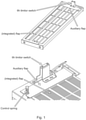
- FIG. 1 shows an example of a flap, switch and control mechanism of an arc mitigation apparatus for an air insulated switchgear and/or of an arc mitigation system for an air insulated switchgear, and where the apparatus and system can be installed in a compartment of an air insulated switchgear.
- Fig. 1 relates to an apparatus that mitigates the effects of an internal arc in a compartment of an air insulated switchgear, a system that mitigates the effects of an internal arc in a compartment of an air insulated switchgear, a compartment for an air insulated switchgear having such internal arc mitigation technologies, as well as to air insulated switchgear that has such internal arc mitigation technologies.
- the arc mitigation apparatus for an air insulated switchgear comprises:
- the new apparatus has a flap installed in a wall of the compartment, and that can be smaller than a normal gas release flap and be auxiliary to the gas release flap, or replace the gas release flap itself.
- the new flap can act alone in mitigating the effect of overpressure or can be auxiliary to other gas release flaps in the compartment. By being auxiliary, it can be smaller and less massive than normal gas release flaps and therefore move more rapidly.
- the movement of the new flap also triggers a switch that can be used to shut down the power source to utilisation of a current limiter, thereby mitigating the effects of the arc itself.
- a control mechanism is usable to adjust how the flap reacts to pressure within the compartment, enabling fine adjustment of the system such that the flap moves and triggers power shutdown at a controlled pressure, that can be a relatively low overpressure enabling the mitigation of low-energy internal arc events that otherwise would not be caught, because such events might not open the normal overpressure gas release flaps but the new adjustable, and if necessary less massive, flap can be adjusted to move at these low pressures and trigger at the same time a current limiting system.
- the switch is an Ith Switch as part of an Ith Limiter, as provided by ABB.
- control mechanism is configured to set a flap threshold pressure for the flap with respect to the pressure difference that will move the flap from the closed position to the open position.
- the flap is an auxiliary flap of a gas-release flap.
- the flap is configured to act as an auxiliary flap of a gas-release flap.
- control mechanism comprises a control spring.
- a simple mechanism is provided by a spring that can be used to set a pressure difference at which the flap begins to move, and/or set how far the flap will move as a function of overpressure or pressure difference thereby enabling precise adjustment of when the flap starts to enables gas to pass and when the switch will be triggered thereby enabling power shutdown to be initiated.
- the switch is configured to activate based on movement of the flap from the closed position to the open position.
- the switch is configured to activate based on movement of the flap away from the closed position.
- the switch is configured to activate based on a magnitude of movement of the flap away from the closed position.
- the switch can be activated as soon as the flap begins to move, or after the flap has moved a certain distance on its movement from the close to open position, or when the flap is moved all the way from close to the open position. This enables, complete control for an operator with respect to when system shutdown will occur and under what circumstances.
- the switch when activated is configured to trigger a current limiter.
- the current limiter is part of a control system configured to rapidly shut down a power source for the switchgear.
- the arc mitigation system for an air insulated switchgear comprises:
- the switch is an Ith Switch.
- control mechanism is configured to set a flap threshold pressure for the flap with respect to the pressure difference that will move the flap from the closed position to the open position.
- the current limiter is part of a control system configured to rapidly shut down a power source for the switchgear.
- the flap is an auxiliary flap of a gas-release flap.
- the flap is configured to act as an auxiliary flap of a gas-release flap.
- control mechanism comprises a control spring.
- the switch is configured to activate based on movement of the flap from the closed position to the open position.
- the switch is configured to activate based on a magnitude of movement of the flap away from the closed position.
- the compartment for an air insulated switchgear comprises:
- the switch is an Ith Switch.
- control mechanism is configured to set a flap threshold pressure for the flap with respect to the pressure difference that will move the flap from the closed position to the open position.
- control mechanism comprises a control spring.
- the flap is an auxiliary flap of a gas-release flap.
- the flap is configured to act as an auxiliary flap of a gas-release flap.
- the switch is configured to activate based on movement of the flap from the closed position to the open position.
- the switch is configured to activate based on movement of the flap away from the closed position.
- the switch is configured to activate based on a magnitude of movement of the flap away from the closed position.
- the switch when activated is configured to trigger a current limiter.
- the current limiter is part of a control system configured to rapidly shut down a power source for the switchgear.
- a medium voltage air insulated switchgear can comprises the above described apparatus.
- a medium voltage air insulated switchgear can comprises the above described system.
- a medium voltage air insulated switchgear can comprises the above described apparatus.
- the flap can for example be a sheet metal part, and can be smaller than normally used to gas release flaps, as shown in figure 1 where the new flap is shown as an auxiliary flap integrated into an existing gas release flap at the top end of the gas release flap adjacent to the switch, which in this case is an Ith limiter switch.
- the flap need not be integrated into an existing gas relief flap, but can be placed into any part of a compartment envelope to provide optimal functionality.
Landscapes
- Engineering & Computer Science (AREA)
- Power Engineering (AREA)
- Gas-Insulated Switchgears (AREA)
Abstract
- a flap;
- a switch; and
- a control mechanism.
Description
- The present invention relates to an arc mitigation apparatus for an air insulated switchgear, an arc mitigation system for an air insulated switchgear, a compartment for an air insulated switchgear, as well as to air insulated switchgear.
- An internal arc fault is one of the most challenging condition for a medium voltage (MV) Air insulated Switchgear (AIS).
- Such MV AIS, also called panels, must meet internal arc classification (IAC) requirements.
- The compartment or compartments of the air insulated switchgear are either built so sturdily that they can withstand the pressure build up due to an internal arc, or pressure relief flaps must open to vent hot gases and particles safely out of the compartment in order that the integrity of the compartment or compartments is maintained.
- Furthermore, current limiters, such an Ith limitors or limiters, are utilized. These are switches, which when operated or triggered when an internal arc fault occurs, ensures that a control system then rapidly shuts down the power source, limiting the damage of the switchgear and/or switch station.
- However, there is a need to provide for better protection in the situation when a low-energy arc fault occurs, which may not lead to operation of the pressure relief flap and/or to operation of the current limiter.
- Therefore, it would be advantageous to have an improved technology that is suitable for the protection of low energy arc faults.
- The object of the present invention is solved with the subject matter of the independent claims, wherein further embodiments are incorporated in the dependent claims.
- In a first aspect, there is provided an arc mitigation apparatus for an air insulated switchgear. The apparatus comprises:
- a flap;
- a switch; and
- a control mechanism.
- In an example, the control mechanism comprises a control spring.
- In an example, the switch is configured to activate based on movement of the flap from the closed position to the open position.
- In an example, the switch is configured to activate based on movement of the flap away from the closed position.
- In an example, the switch is configured to activate based on a magnitude of movement of the flap away from the closed position.
- In an example, the switch when activated is configured to trigger a current limiter.
- In a second aspect, there is provided an arc mitigation system for an air insulated switchgear. The system comprises:
- a flap;
- a switch;
- a control mechanism; and
- a current limiter.
- In an example, the control mechanism comprises a control spring.
- In an example, the switch is configured to activate based on movement of the flap from the closed position to the open position.
- In an example, the switch is configured to activate based on movement of the flap away from the closed position.
- In an example, the switch is configured to activate based on a magnitude of movement of the flap away from the closed position.
- In a third aspect, there is provided a compartment for an air insulated switchgear. The compartment comprises:
- a flap;
- a switch; and
- a control mechanism.
- In a fourth aspect, there is provided a medium voltage air insulated switchgear comprising an apparatus according to the first aspect.
- In a fifth aspect, there is provided a medium voltage air insulated switchgear comprising a system according to the second aspect.
- In a sixth aspect, there is provided a medium voltage air insulated switchgear comprising a current limiting apparatus according to the third aspect.
- The above aspects and examples will become apparent from and be elucidated with reference to the embodiments described hereinafter.
- Exemplary embodiments will be described in the following with reference to the following drawing:
Fig. 1 shows an example of a flap, switch and control mechanism of an arc mitigation apparatus for an air insulated switchgear and/or of an arc mitigation system for an air insulated switchgear, and where the apparatus and system can be installed in a compartment of an air insulated switchgear. -
Fig. 1 relates to an apparatus that mitigates the effects of an internal arc in a compartment of an air insulated switchgear, a system that mitigates the effects of an internal arc in a compartment of an air insulated switchgear, a compartment for an air insulated switchgear having such internal arc mitigation technologies, as well as to air insulated switchgear that has such internal arc mitigation technologies. - The arc mitigation apparatus for an air insulated switchgear comprises:
- a flap;
- a switch; and
- a control mechanism.
- Thus, when an internal arc event fault occurs within a compartment of an air insulated switchgear, there is an extremely rapid rise in temperature, gases are released and the air and gases are heated to very high temperatures very rapidly, leading to very high pressures that can be dangerous. At the same time the arc itself can lead to damage of the switchgear and other systems. The new apparatus, has a flap installed in a wall of the compartment, and that can be smaller than a normal gas release flap and be auxiliary to the gas release flap, or replace the gas release flap itself. However, the pressure increasing the compartment leads to movement of the flap from a closed position to an open position, thereby venting gas from the compartment and mitigating the effects of overpressure and a compartment - as discussed, the new flap can act alone in mitigating the effect of overpressure or can be auxiliary to other gas release flaps in the compartment. By being auxiliary, it can be smaller and less massive than normal gas release flaps and therefore move more rapidly. The movement of the new flap also triggers a switch that can be used to shut down the power source to utilisation of a current limiter, thereby mitigating the effects of the arc itself. A control mechanism is usable to adjust how the flap reacts to pressure within the compartment, enabling fine adjustment of the system such that the flap moves and triggers power shutdown at a controlled pressure, that can be a relatively low overpressure enabling the mitigation of low-energy internal arc events that otherwise would not be caught, because such events might not open the normal overpressure gas release flaps but the new adjustable, and if necessary less massive, flap can be adjusted to move at these low pressures and trigger at the same time a current limiting system.
- In an example, the switch is an Ith Switch as part of an Ith Limiter, as provided by ABB.
- In an example, the control mechanism is configured to set a flap threshold pressure for the flap with respect to the pressure difference that will move the flap from the closed position to the open position.
- In an example, the flap is an auxiliary flap of a gas-release flap.
- In an example, the flap is configured to act as an auxiliary flap of a gas-release flap.
- According to an example, the control mechanism comprises a control spring.
- Thus, a simple mechanism is provided by a spring that can be used to set a pressure difference at which the flap begins to move, and/or set how far the flap will move as a function of overpressure or pressure difference thereby enabling precise adjustment of when the flap starts to enables gas to pass and when the switch will be triggered thereby enabling power shutdown to be initiated.
- According to an example, the switch is configured to activate based on movement of the flap from the closed position to the open position.
- According to an example, the switch is configured to activate based on movement of the flap away from the closed position.
- According to an example, the switch is configured to activate based on a magnitude of movement of the flap away from the closed position.
- Thus, the switch can be activated as soon as the flap begins to move, or after the flap has moved a certain distance on its movement from the close to open position, or when the flap is moved all the way from close to the open position. This enables, complete control for an operator with respect to when system shutdown will occur and under what circumstances.
- According to an example, the switch when activated is configured to trigger a current limiter.
- In an example, the current limiter is part of a control system configured to rapidly shut down a power source for the switchgear.
- The arc mitigation system for an air insulated switchgear comprises:
- a flap;
- a switch;
- a control mechanism; and
- a current limiter.
- In an example, the switch is an Ith Switch.
- In an example, the control mechanism is configured to set a flap threshold pressure for the flap with respect to the pressure difference that will move the flap from the closed position to the open position.
- In an example, the current limiter is part of a control system configured to rapidly shut down a power source for the switchgear.
- In an example, the flap is an auxiliary flap of a gas-release flap.
- In an example, the flap is configured to act as an auxiliary flap of a gas-release flap.
- According to an example, the control mechanism comprises a control spring.
- According to an example, the switch is configured to activate based on movement of the flap from the closed position to the open position.
- System according to any of claims 7-9, wherein the switch is configured to activate based on movement of the flap away from the closed position.
- According to an example, the switch is configured to activate based on a magnitude of movement of the flap away from the closed position.
- The compartment for an air insulated switchgear comprises:
- a flap;
- a switch; and
- a control mechanism.
- In an example, the switch is an Ith Switch.
- In an example, the control mechanism is configured to set a flap threshold pressure for the flap with respect to the pressure difference that will move the flap from the closed position to the open position.
- In an example, the control mechanism comprises a control spring.
- In an example, the flap is an auxiliary flap of a gas-release flap.
- In an example, the flap is configured to act as an auxiliary flap of a gas-release flap.
- In an example, the switch is configured to activate based on movement of the flap from the closed position to the open position.
- In an example, the switch is configured to activate based on movement of the flap away from the closed position.
- In an example, the switch is configured to activate based on a magnitude of movement of the flap away from the closed position.
- In an example, the switch when activated is configured to trigger a current limiter.
- In an example, the current limiter is part of a control system configured to rapidly shut down a power source for the switchgear.
- From the above description, it is clear that a medium voltage air insulated switchgear can comprises the above described apparatus.
- From the above description, it is clear that a medium voltage air insulated switchgear can comprises the above described system.
- From the above description, it is clear that a medium voltage air insulated switchgear can comprises the above described apparatus.
- Thus, a response in terms of pressure and speed is improved with respect to addressing an internal arc event, where the control mechanism that can be in the form of a spring can be used to control this response. A faster and/or more sensitive response is achieved.
- By having an improved response, low-energy internal arc events can be mitigated and for all internal arc fault events, the energy released in the compartment during the internal arc is reduced, limiting the damage to the compartment and/or switchgear and improving the safety to personnel.
- The flap can for example be a sheet metal part, and can be smaller than normally used to gas release flaps, as shown in
figure 1 where the new flap is shown as an auxiliary flap integrated into an existing gas release flap at the top end of the gas release flap adjacent to the switch, which in this case is an Ith limiter switch. The flap need not be integrated into an existing gas relief flap, but can be placed into any part of a compartment envelope to provide optimal functionality. - While the invention has been illustrated and described in detail in the drawing and foregoing description, such illustration and description are to be considered illustrative or exemplary and not restrictive. The invention is not limited to the disclosed embodiments. Other variations to the disclosed embodiments can be understood and effected by those skilled in the art in practicing a claimed invention, from a study of the drawings, the disclosure, and the dependent claims.
Claims (15)
- An arc mitigation apparatus for an air insulated switchgear, the apparatus comprising:- a flap;- a switch; and- a control mechanism;
wherein, the flap is configured to be installed in a wall of a compartment of a medium voltage switchgear;
wherein, when the flap is installed in the wall of the compartment of the medium voltage switchgear the flap is configured to permit when open air and/or gas to pass through the flap from inside the compartment to outside the compartment;
wherein, when the flap is installed in the wall of the compartment of a medium voltage switchgear the flap is configured to move from a closed position to an open position due to a pressure difference between the inside of the compartment and the outside of the compartment;
wherein, the switch is configured to activate based on movement of the flap; and
wherein, the control mechanism is configured to set a flap threshold pressure for the flap with respect to the pressure difference that will move the flap. - Apparatus according to claim 1, wherein the control mechanism comprises a control spring.
- Apparatus according to any of claims 1-2, wherein the switch is configured to activate based on movement of the flap from the closed position to the open position.
- Apparatus according to any of claims 1-3, wherein the switch is configured to activate based on movement of the flap away from the closed position.
- Apparatus according to any of claims 1-4, wherein the switch is configured to activate based on a magnitude of movement of the flap away from the closed position.
- Apparatus according to any of claims 1-5, wherein the switch when activated is configured to trigger a current limiter.
- An arc mitigation system for an air insulated switchgear, the system comprising:- a flap;- a switch;- a control mechanism; and- a current limiter;
wherein, the flap is configured to be installed in a wall of a compartment of a medium voltage switchgear;
wherein, when the flap is installed in the wall of the compartment of a medium voltage switchgear the flap is configured to permit when open air and/or gas to pass through the flap from inside the compartment to outside the compartment;
wherein, when the flap is installed in the wall of the compartment of a medium voltage switchgear the flap is configured to move from a closed position to an open position due to a pressure difference between the inside of the compartment and the outside of the compartment;
wherein, the control mechanism is configured to set a flap threshold pressure for the flap with respect to the pressure difference that will move the flap;
wherein, the switch is configured to activate based on movement of the flap; and
wherein, activation of the switch is configured to trigger the current limiter. - System according to claim 7, wherein the control mechanism comprises a control spring.
- System according to any of claims 7-8, wherein the switch is configured to activate based on movement of the flap from the closed position to the open position.
- System according to any of claims 7-9, wherein the switch is configured to activate based on movement of the flap away from the closed position.
- System according to any of claims 7-10, wherein the switch is configured to activate based on a magnitude of movement of the flap away from the closed position.
- A compartment for an air insulated switchgear, the compartment comprising:- a flap;- a switch; and- a control mechanism;
wherein, the flap is installed in a wall of the compartment;
wherein, the flap is configured to permit when open air and/or gas to pass through the flap from inside the compartment to outside the compartment;
wherein, the flap is configured to move from a closed position to an open position due to a pressure difference between the inside of the compartment and the outside of the compartment;
wherein, the switch is configured to activate based on movement of the flap; and
wherein, the control mechanism is configured to set a flap threshold pressure for the flap with respect to the pressure difference that will move the flap. - A medium voltage air insulated switchgear comprising an apparatus according to any of claims 1-5.
- A medium voltage air insulated switchgear comprising a system according to any of claims 7-11.
- A medium voltage air insulated switchgear comprising a compartment according to claim 12.
Priority Applications (3)
| Application Number | Priority Date | Filing Date | Title |
|---|---|---|---|
| EP20189410.2A EP3952043A1 (en) | 2020-08-04 | 2020-08-04 | Arc apparatus for an air insulated switchgear |
| US17/384,828 US11824329B2 (en) | 2020-08-04 | 2021-07-26 | Arc apparatus for an air insulated switchgear |
| CN202110880905.2A CN114068235B (en) | 2020-08-04 | 2021-08-02 | Arc device for air-insulated switchgear |
Applications Claiming Priority (1)
| Application Number | Priority Date | Filing Date | Title |
|---|---|---|---|
| EP20189410.2A EP3952043A1 (en) | 2020-08-04 | 2020-08-04 | Arc apparatus for an air insulated switchgear |
Publications (1)
| Publication Number | Publication Date |
|---|---|
| EP3952043A1 true EP3952043A1 (en) | 2022-02-09 |
Family
ID=71948513
Family Applications (1)
| Application Number | Title | Priority Date | Filing Date |
|---|---|---|---|
| EP20189410.2A Pending EP3952043A1 (en) | 2020-08-04 | 2020-08-04 | Arc apparatus for an air insulated switchgear |
Country Status (3)
| Country | Link |
|---|---|
| US (1) | US11824329B2 (en) |
| EP (1) | EP3952043A1 (en) |
| CN (1) | CN114068235B (en) |
Citations (5)
| Publication number | Priority date | Publication date | Assignee | Title |
|---|---|---|---|---|
| SU691972A1 (en) * | 1977-07-05 | 1979-10-15 | Предприятие П/Я В-8833 | Outfit distribution arrangement |
| JPS5889008A (en) * | 1981-11-19 | 1983-05-27 | 株式会社東芝 | Enclosed switchboard |
| KR101381848B1 (en) * | 2013-12-24 | 2014-04-10 | 주식회사 리폼테크 | Pressure exhaust apparatus for metal-clad switchgear |
| US20150372463A1 (en) * | 2014-06-24 | 2015-12-24 | General Electric Company | Switchgear housing including a floating exhaust flap assembly |
| EP3671788A1 (en) * | 2018-12-17 | 2020-06-24 | ABB Schweiz AG | Overpressure relief flap apparatus for a medium or high voltage switchgear |
Family Cites Families (8)
| Publication number | Priority date | Publication date | Assignee | Title |
|---|---|---|---|---|
| JP5889008B2 (en) | 2012-01-31 | 2016-03-22 | 三菱電機株式会社 | Information display device and information display method |
| WO2014172886A1 (en) * | 2013-04-26 | 2014-10-30 | General Electric Company | Switchgear housing including pressure relief member |
| US10431963B2 (en) * | 2015-02-19 | 2019-10-01 | Abb Schweiz Ag | Exhaust system for switchgear enclosure, and switchgear enclosure having the same |
| US9899810B2 (en) * | 2015-11-24 | 2018-02-20 | Abb Schweiz Ag | Switchgear enclosure with improved venting |
| US10347437B2 (en) * | 2015-12-04 | 2019-07-09 | Abb Schweiz Ag | Disconnector device and arrangement for disconnecting a contactor |
| US10332704B2 (en) * | 2016-04-19 | 2019-06-25 | Abb Schweiz Ag | Devices, systems, and methods for protection of switchgear against electrical arcs |
| KR102488657B1 (en) * | 2018-02-20 | 2023-01-16 | 엘에스일렉트릭(주) | switchboard |
| EP3582347A1 (en) * | 2018-06-13 | 2019-12-18 | ABB Schweiz AG | Electrical connection assembly in an electrical switchgear |
-
2020
- 2020-08-04 EP EP20189410.2A patent/EP3952043A1/en active Pending
-
2021
- 2021-07-26 US US17/384,828 patent/US11824329B2/en active Active
- 2021-08-02 CN CN202110880905.2A patent/CN114068235B/en active Active
Patent Citations (5)
| Publication number | Priority date | Publication date | Assignee | Title |
|---|---|---|---|---|
| SU691972A1 (en) * | 1977-07-05 | 1979-10-15 | Предприятие П/Я В-8833 | Outfit distribution arrangement |
| JPS5889008A (en) * | 1981-11-19 | 1983-05-27 | 株式会社東芝 | Enclosed switchboard |
| KR101381848B1 (en) * | 2013-12-24 | 2014-04-10 | 주식회사 리폼테크 | Pressure exhaust apparatus for metal-clad switchgear |
| US20150372463A1 (en) * | 2014-06-24 | 2015-12-24 | General Electric Company | Switchgear housing including a floating exhaust flap assembly |
| EP3671788A1 (en) * | 2018-12-17 | 2020-06-24 | ABB Schweiz AG | Overpressure relief flap apparatus for a medium or high voltage switchgear |
Non-Patent Citations (1)
| Title |
|---|
| FARIED SAMY ET AL: "Arc flash - New regulations and the advantages of the ultra fast grounding switch", 2017 PETROLEUM AND CHEMICAL INDUSTRY TECHNICAL CONFERENCE (PCIC), IEEE, 18 September 2017 (2017-09-18), pages 245 - 252, XP033268619, DOI: 10.1109/PCICON.2017.8188743 * |
Also Published As
| Publication number | Publication date |
|---|---|
| US20220045488A1 (en) | 2022-02-10 |
| CN114068235B (en) | 2024-10-11 |
| US11824329B2 (en) | 2023-11-21 |
| CN114068235A (en) | 2022-02-18 |
Similar Documents
| Publication | Publication Date | Title |
|---|---|---|
| EP3667677A1 (en) | Depressurisation valve | |
| JP6299507B2 (en) | Protection device for solar power generation system and protection method for solar power generation system | |
| EP3952043A1 (en) | Arc apparatus for an air insulated switchgear | |
| CN111585256B (en) | Control method and device for hybrid cascade multi-end converter valve | |
| JP2000215768A (en) | Vacuum switchgear | |
| CN121172628B (en) | Self-adaptive protection device for ring main unit | |
| KR101619605B1 (en) | Device for preventing over pressure of fuel cell cooling system | |
| US2584710A (en) | Protective system for series capacitors | |
| EP4084251B1 (en) | Power source reverse connection prevention circuit, power distribution apparatus, and power supply and distribution system | |
| KR101837649B1 (en) | Apparatus and method for controlling a circuit breaker of STATCOM | |
| WO2020197516A1 (en) | Double secured safety valve | |
| JPS58164163A (en) | Stop control method of fuel cell generator | |
| EP4109481B1 (en) | Overpressure relief flap apparatus for a medium or high voltage switchgear | |
| GB2252671A (en) | High power switching arrangement | |
| GB2060982A (en) | Arrangement for shutting off a safety valve equipped with a blowoff conduit | |
| EP3399533B1 (en) | Method and device for controlling opening/closing of circuit breaker | |
| JP4120540B2 (en) | DC feeding network protection method and DC feeding network protection system | |
| EP4462620A1 (en) | Fault arc protection: circuit breaker system to interrupt faulty section | |
| EP4107831B1 (en) | Shoot through current detection and protection circuit | |
| AU2003244542B2 (en) | Current switching | |
| JPH03144182A (en) | Control for vacuum protecting device | |
| CN121843021A (en) | Explosion-proof device and method capable of realizing instantaneous separation and self-recovery | |
| JPH0534483A (en) | Pressure relieving device of nuclear reactor containment vessel | |
| WO2024235787A1 (en) | Circuit breaker system with reduced own time: fault protection | |
| JP2005085869A (en) | Electrical equipment |
Legal Events
| Date | Code | Title | Description |
|---|---|---|---|
| PUAI | Public reference made under article 153(3) epc to a published international application that has entered the european phase |
Free format text: ORIGINAL CODE: 0009012 |
|
| STAA | Information on the status of an ep patent application or granted ep patent |
Free format text: STATUS: THE APPLICATION HAS BEEN PUBLISHED |
|
| AK | Designated contracting states |
Kind code of ref document: A1 Designated state(s): AL AT BE BG CH CY CZ DE DK EE ES FI FR GB GR HR HU IE IS IT LI LT LU LV MC MK MT NL NO PL PT RO RS SE SI SK SM TR |
|
| STAA | Information on the status of an ep patent application or granted ep patent |
Free format text: STATUS: REQUEST FOR EXAMINATION WAS MADE |
|
| 17P | Request for examination filed |
Effective date: 20220704 |
|
| RBV | Designated contracting states (corrected) |
Designated state(s): AL AT BE BG CH CY CZ DE DK EE ES FI FR GB GR HR HU IE IS IT LI LT LU LV MC MK MT NL NO PL PT RO RS SE SI SK SM TR |
|
| STAA | Information on the status of an ep patent application or granted ep patent |
Free format text: STATUS: EXAMINATION IS IN PROGRESS |
|
| 17Q | First examination report despatched |
Effective date: 20240402 |