EP3952038A1 - Laser device - Google Patents
Laser device Download PDFInfo
- Publication number
- EP3952038A1 EP3952038A1 EP20777511.5A EP20777511A EP3952038A1 EP 3952038 A1 EP3952038 A1 EP 3952038A1 EP 20777511 A EP20777511 A EP 20777511A EP 3952038 A1 EP3952038 A1 EP 3952038A1
- Authority
- EP
- European Patent Office
- Prior art keywords
- optical
- combiners
- laser apparatus
- ablation
- laser
- Prior art date
- Legal status (The legal status is an assumption and is not a legal conclusion. Google has not performed a legal analysis and makes no representation as to the accuracy of the status listed.)
- Granted
Links
Images


Classifications
-
- H—ELECTRICITY
- H01—ELECTRIC ELEMENTS
- H01S—DEVICES USING THE PROCESS OF LIGHT AMPLIFICATION BY STIMULATED EMISSION OF RADIATION [LASER] TO AMPLIFY OR GENERATE LIGHT; DEVICES USING STIMULATED EMISSION OF ELECTROMAGNETIC RADIATION IN WAVE RANGES OTHER THAN OPTICAL
- H01S5/00—Semiconductor lasers
- H01S5/40—Arrangement of two or more semiconductor lasers, not provided for in groups H01S5/02 - H01S5/30
- H01S5/4012—Beam combining, e.g. by the use of fibres, gratings, polarisers, prisms
-
- A—HUMAN NECESSITIES
- A61—MEDICAL OR VETERINARY SCIENCE; HYGIENE
- A61B—DIAGNOSIS; SURGERY; IDENTIFICATION
- A61B18/00—Surgical instruments, devices or methods for transferring non-mechanical forms of energy to or from the body
- A61B18/18—Surgical instruments, devices or methods for transferring non-mechanical forms of energy to or from the body by applying electromagnetic radiation, e.g. microwaves
- A61B18/20—Surgical instruments, devices or methods for transferring non-mechanical forms of energy to or from the body by applying electromagnetic radiation, e.g. microwaves using laser
- A61B18/22—Surgical instruments, devices or methods for transferring non-mechanical forms of energy to or from the body by applying electromagnetic radiation, e.g. microwaves using laser the beam being directed along or through a flexible conduit, e.g. an optical fibre; Couplings or hand-pieces therefor
- A61B18/24—Surgical instruments, devices or methods for transferring non-mechanical forms of energy to or from the body by applying electromagnetic radiation, e.g. microwaves using laser the beam being directed along or through a flexible conduit, e.g. an optical fibre; Couplings or hand-pieces therefor with a catheter
-
- H—ELECTRICITY
- H01—ELECTRIC ELEMENTS
- H01S—DEVICES USING THE PROCESS OF LIGHT AMPLIFICATION BY STIMULATED EMISSION OF RADIATION [LASER] TO AMPLIFY OR GENERATE LIGHT; DEVICES USING STIMULATED EMISSION OF ELECTROMAGNETIC RADIATION IN WAVE RANGES OTHER THAN OPTICAL
- H01S5/00—Semiconductor lasers
- H01S5/005—Optical components external to the laser cavity, specially adapted therefor, e.g. for homogenisation or merging of the beams or for manipulating laser pulses, e.g. pulse shaping
-
- H—ELECTRICITY
- H01—ELECTRIC ELEMENTS
- H01S—DEVICES USING THE PROCESS OF LIGHT AMPLIFICATION BY STIMULATED EMISSION OF RADIATION [LASER] TO AMPLIFY OR GENERATE LIGHT; DEVICES USING STIMULATED EMISSION OF ELECTROMAGNETIC RADIATION IN WAVE RANGES OTHER THAN OPTICAL
- H01S5/00—Semiconductor lasers
- H01S5/02—Structural details or components not essential to laser action
- H01S5/022—Mountings; Housings
- H01S5/0239—Combinations of electrical or optical elements
-
- A—HUMAN NECESSITIES
- A61—MEDICAL OR VETERINARY SCIENCE; HYGIENE
- A61B—DIAGNOSIS; SURGERY; IDENTIFICATION
- A61B18/00—Surgical instruments, devices or methods for transferring non-mechanical forms of energy to or from the body
- A61B2018/00571—Surgical instruments, devices or methods for transferring non-mechanical forms of energy to or from the body for achieving a particular surgical effect
- A61B2018/00577—Ablation
-
- A—HUMAN NECESSITIES
- A61—MEDICAL OR VETERINARY SCIENCE; HYGIENE
- A61B—DIAGNOSIS; SURGERY; IDENTIFICATION
- A61B18/00—Surgical instruments, devices or methods for transferring non-mechanical forms of energy to or from the body
- A61B18/18—Surgical instruments, devices or methods for transferring non-mechanical forms of energy to or from the body by applying electromagnetic radiation, e.g. microwaves
- A61B18/20—Surgical instruments, devices or methods for transferring non-mechanical forms of energy to or from the body by applying electromagnetic radiation, e.g. microwaves using laser
- A61B2018/2035—Beam shaping or redirecting; Optical components therefor
- A61B2018/20554—Arrangements for particular intensity distribution, e.g. tophat
-
- A—HUMAN NECESSITIES
- A61—MEDICAL OR VETERINARY SCIENCE; HYGIENE
- A61B—DIAGNOSIS; SURGERY; IDENTIFICATION
- A61B18/00—Surgical instruments, devices or methods for transferring non-mechanical forms of energy to or from the body
- A61B18/18—Surgical instruments, devices or methods for transferring non-mechanical forms of energy to or from the body by applying electromagnetic radiation, e.g. microwaves
- A61B18/20—Surgical instruments, devices or methods for transferring non-mechanical forms of energy to or from the body by applying electromagnetic radiation, e.g. microwaves using laser
- A61B18/22—Surgical instruments, devices or methods for transferring non-mechanical forms of energy to or from the body by applying electromagnetic radiation, e.g. microwaves using laser the beam being directed along or through a flexible conduit, e.g. an optical fibre; Couplings or hand-pieces therefor
- A61B2018/2205—Characteristics of fibres
- A61B2018/2211—Plurality of fibres
-
- A—HUMAN NECESSITIES
- A61—MEDICAL OR VETERINARY SCIENCE; HYGIENE
- A61B—DIAGNOSIS; SURGERY; IDENTIFICATION
- A61B18/00—Surgical instruments, devices or methods for transferring non-mechanical forms of energy to or from the body
- A61B18/18—Surgical instruments, devices or methods for transferring non-mechanical forms of energy to or from the body by applying electromagnetic radiation, e.g. microwaves
- A61B18/20—Surgical instruments, devices or methods for transferring non-mechanical forms of energy to or from the body by applying electromagnetic radiation, e.g. microwaves using laser
- A61B18/22—Surgical instruments, devices or methods for transferring non-mechanical forms of energy to or from the body by applying electromagnetic radiation, e.g. microwaves using laser the beam being directed along or through a flexible conduit, e.g. an optical fibre; Couplings or hand-pieces therefor
- A61B2018/2244—Features of optical fibre cables, e.g. claddings
-
- G—PHYSICS
- G02—OPTICS
- G02B—OPTICAL ELEMENTS, SYSTEMS OR APPARATUS
- G02B6/00—Light guides; Structural details of arrangements comprising light guides and other optical elements, e.g. couplings
- G02B6/24—Coupling light guides
- G02B6/42—Coupling light guides with opto-electronic elements
- G02B6/4201—Packages, e.g. shape, construction, internal or external details
- G02B6/4249—Packages, e.g. shape, construction, internal or external details comprising arrays of active devices and fibres
- G02B6/425—Optical features
-
- G—PHYSICS
- G02—OPTICS
- G02B—OPTICAL ELEMENTS, SYSTEMS OR APPARATUS
- G02B6/00—Light guides; Structural details of arrangements comprising light guides and other optical elements, e.g. couplings
- G02B6/24—Coupling light guides
- G02B6/42—Coupling light guides with opto-electronic elements
- G02B6/4201—Packages, e.g. shape, construction, internal or external details
- G02B6/4287—Optical modules with tapping or launching means through the surface of the waveguide
-
- H—ELECTRICITY
- H01—ELECTRIC ELEMENTS
- H01S—DEVICES USING THE PROCESS OF LIGHT AMPLIFICATION BY STIMULATED EMISSION OF RADIATION [LASER] TO AMPLIFY OR GENERATE LIGHT; DEVICES USING STIMULATED EMISSION OF ELECTROMAGNETIC RADIATION IN WAVE RANGES OTHER THAN OPTICAL
- H01S2301/00—Functional characteristics
- H01S2301/20—Lasers with a special output beam profile or cross-section, e.g. non-Gaussian
- H01S2301/206—Top hat profile
-
- H—ELECTRICITY
- H01—ELECTRIC ELEMENTS
- H01S—DEVICES USING THE PROCESS OF LIGHT AMPLIFICATION BY STIMULATED EMISSION OF RADIATION [LASER] TO AMPLIFY OR GENERATE LIGHT; DEVICES USING STIMULATED EMISSION OF ELECTROMAGNETIC RADIATION IN WAVE RANGES OTHER THAN OPTICAL
- H01S5/00—Semiconductor lasers
- H01S5/02—Structural details or components not essential to laser action
- H01S5/022—Mountings; Housings
- H01S5/0225—Out-coupling of light
- H01S5/02251—Out-coupling of light using optical fibres
-
- H—ELECTRICITY
- H01—ELECTRIC ELEMENTS
- H01S—DEVICES USING THE PROCESS OF LIGHT AMPLIFICATION BY STIMULATED EMISSION OF RADIATION [LASER] TO AMPLIFY OR GENERATE LIGHT; DEVICES USING STIMULATED EMISSION OF ELECTROMAGNETIC RADIATION IN WAVE RANGES OTHER THAN OPTICAL
- H01S5/00—Semiconductor lasers
- H01S5/40—Arrangement of two or more semiconductor lasers, not provided for in groups H01S5/02 - H01S5/30
- H01S5/4025—Array arrangements, e.g. constituted by discrete laser diodes or laser bar
Definitions
- the present invention relates to a laser apparatus.
- laser apparatus for providing a medical treatment by inserting a catheter into the patient's body and irradiating a target area, such as an affected area, with a laser light from the tip of an optical fiber inside the catheter.
- a target area such as an affected area
- laser light flatness there is a case where a beam of a laser light high in flatness of the beam profile is used, other than Gaussian light. Note that, hereinafter, the flatness of the beam profile of a laser light will be simply referred to as "laser light flatness”.
- Patent Literature 1 discloses a configuration that improves the laser light flatness by inputting lights guided through a plurality of optical waveguides into the incident end of an optical transmitter, and transmitting the lights while confining the lights in the optical transmission region of the optical transmitter.
- Patent Literature 2 discloses a configuration for converting a Gaussian beam at a multi-mode optical fiber output into a flat top beam.
- Patent Literature 3 discloses a configuration equipped with a beam shaping optical element that redistributes the light emitted by a high-brightness light source into an emission optical beam having a far-field beam sectional profile with a spatially flat optical intensity distribution.
- each of Patent Literatures 1 to 3 entails problems in that, for example, the configuration cannot be used in a thin tube, such as a medical catheter or the like, because the apparatus configuration is complicated or requires a large placement space.
- the present invention has been made in consideration of the above, and has an object to provide a laser apparatus that is excellent in space saving property and can improve the laser light flatness.
- a laser apparatus includes: one or more laser diodes and two or more optical combiners. Further, an output side of the laser diodes is connected to an input side of one of the optical combiners, and an output side of the one of the optical combiners is connected to an input side of another optical combiner.
- the optical combiners include an input/output provided with a multi-mode optical fiber.
- the optical combiners are a 2:1 optical combiner.
- the optical combiners include two optical combiners, of which an output side of a first optical combiner is connected to an input side of a second optical combiner.
- the optical combiners include three optical combiners, of which an output side of a first optical combiner is connected to an input side of a second optical combiner, and an output side of the second optical combiner is connected to an input side of a third optical combiner.
- the laser diodes includes an output provided with a multi-mode optical fiber.
- the laser diodes include two or more laser diodes, in which the laser diodes are individually connected to input sides of separate optical combiners.
- a number of the laser diodes is smaller than the total number of input ports of the optical combiners.
- the laser apparatus includes an asymmetric tap coupler. Further, an input side of the asymmetric tap coupler is connected to an output side of one of the optical combiners arranged in a rearmost stage.
- the present invention it is possible to improve the laser light flatness without requiring a large space, by connecting a plurality of optical combiners in a cascade state.
- a laser apparatus is characterized in that the laser apparatus includes one or more ablation-related laser diodes (each of which will be referred to as "ablation-related LD", hereinafter) and two or more optical combiners, and that the optical combiners are connected to each other in series (cascade connection).
- ablation-related LD ablation-related laser diodes
- optical combiners are connected to each other in series (cascade connection).
- a laser apparatus 1 includes, as illustrated in FIG. 1 , two ablation-related LDs 11a and 11b, two optical combiners 12a and 12b, and optical fibers 13 arranged between the ablation-related LDs 11a and 11b and the optical combiners 12a and 12b.
- the plurality of ablation-related LDs are expressed as "ablation-related LDs 11" when being collectively referred to
- the plurality of optical combiners are expressed as "optical combiners 12", when being collectively referred to.
- the ablation-related light output from each ablation-related LD 11 is a light in a wavelength bandwidth, which is the so-called "living window", that is, a light in a wavelength bandwidth of 600 nm to 1,500 nm. Further, the output of each ablation-related LD 11 is set to 0.1 W or more, for example.
- the respective ablation-related LDs 11 may be connected to each other, for example, in series, and may be configured to be supplied with a common current from the same power supply, or may be configured to be supplied with different currents from separate power supplies. In this respect, when the ablation-related LDs 11 are supplied with currents from separate power supplies, there is an advantage that the mixing ratio of the laser lights from the respective ablation-related LDs 11 can be changed.
- the ablation-related LD 11a is connected to the input side of the optical combiner 12b via an optical fiber 13. Further, the ablation-related LD 11b is connected to the input side of the optical combiner 12a via an optical fiber 13.
- the optical fiber 13 used as the output port of each ablation-related LD 11 is formed of a multi-mode optical fiber or single-mode optical fiber. Here, the length of the optical fiber 13 is about 1 m, for example.
- the two ablation-related LDs 11 are individually connected to the separate optical combiners 12, and, further, the number of ablation-related LDs 11 connected to each optical combiner 12 is minimized, by which the decrease in the efficiency can be suppressed. Further, when the two ablation-related LDs 11 are individually connected to the separate optical combiners 12, lights that have been made different in propagation mode type are mixed by the optical combiner 12 in the subsequent stage, and the laser light flatness is thereby improved.
- the number of ablation-related LDs 11 is preferably smaller than the total number of input ports of the optical combiners 12.
- the optical combiners 12 preferably include one or more input ports to which no ablation-related LD 11 is connected.
- the "input port” means a port other than the port connected to another optical combiner 12 among the ports on the input side of each optical combiner 12.
- the laser apparatus 1 illustrated in FIG. 1 is configured such that the number of ablation-related LDs 11 is two, and the total number of input ports of the optical combiners 12 is three.
- Each of the optical combiners 12 serves to multiplex (synthesize) a plurality of lights.
- Each of the optical fibers 13 used as the input port and the output port of each optical combiner 12 is formed of a multi-mode optical fiber.
- This optical fiber 13 has, for example, a core diameter of 105 ⁇ m and a clad diameter of 125 ⁇ m, and is composed of a step-index type optical fiber including a coating, such as an acrylate coating film or polyimide coating film.
- Each of the optical combiners 12 is an N:1 optical combiner, and preferably a 2:1 optical combiner. Further, each optical combiner 12 is a combiner of an end couple type or side couple type. Further, the respective optical combiners 12 are mounted on the same plate made of a metal. This metal plate also functions as a heat dissipation plate.
- the output side of the optical combiner 12a is connected to the input side of the optical combiner 12b via an optical fiber 13. Further, the output side of the optical combiner 12b is connected to an optical output section 21 via an optical fiber 13.
- a light source for example, a monitor-related LD or the like
- other than the ablation-related LDs 11 may be connected thereto.
- the number of continuous connection stages of the optical combiners 12 is set to be not more than two, by which the decrease in the efficiency can be suppressed as much as possible.
- the optical combiner 12b which is in the subsequent stage, of the optical combiners 12a and 12b, may be equipped with a heat dissipation mechanism (for example, a heat dissipation plate) to suppress heat generation.
- the optical output section 21 serves to output the light multiplexed by the optical combiner 12b.
- the specific configuration of the optical output section 21 depends on the application of the laser apparatus 1. For example, when the laser apparatus 1 is used for a laser medical treatment by a medical catheter, the optical output section 21 is composed of an optical probe or the like.
- the laser apparatus 1 configured as described above, since the plurality of optical combiners 12a and 12b are connected in a cascade state, it is possible to improve the laser light flatness without requiring a large space. Further, in the laser apparatus 1, since the two ablation-related LDs 11a and 11b are individually connected to the separate optical combiners 12a and 12b, lights that have been made different in propagation mode type are mixed by the optical combiner 12b in the subsequent stage, so it is possible to improve the laser light flatness.
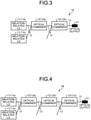
- a laser apparatus 1A includes, as illustrated in FIG. 3 , two ablation-related LDs 11a and 11b, two optical combiners 12a and 12b, and optical fibers 13 arranged between the ablation-related LDs 11a and 11b and the optical combiners 12a and 12b.
- the configurations of the ablation-related LDs 11, the optical combiners 12, the optical fibers 13, and the optical output section 21, illustrated in FIG. 3 are the same as those of the first embodiment described above.
- the ablation-related LDs 11a and 11b are connected to the input side of the optical combiner 12a via optical fibers 13. Further, the output side of the optical combiner 12a is connected to the input side of the optical combiner 12b via an optical fiber 13. Further, the output side of the optical combiner 12b is connected to the optical output section 21 via an optical fiber 13. In this way, in the laser apparatus 1A according to this embodiment, the two ablation-related LDs 11a and 11b are connected to the input side of the same optical combiner 12a, and no ablation-related LD 11 is connected to the optical combiner 12b arranged in the second stage.
- the plurality of optical combiners 12a and 12b are connected in a cascade state, it is possible to improve the laser light flatness without requiring a large space.
- a laser apparatus 1B includes, as illustrated in FIG. 4 , two ablation-related LDs 11a and 11b, three optical combiners 12a, 12b, and 12c, and optical fibers 13 arranged between the ablation-related LDs 11a and 11b and the optical combiners 12a, 12b, and 12c.
- the configurations of the ablation-related LDs 11, the optical combiners 12, the optical fibers 13, and the optical output section 21, illustrated in FIG. 4 are the same as those of the first embodiment described above.
- the ablation-related LDs 11a and 11b are connected to the input side of the optical combiner 12a via optical fibers 13. Further, the output side of the optical combiner 12a is connected to the input side of the optical combiner 12b via an optical fiber 13. Further, the output side of the optical combiner 12b is connected to the input side of the optical combiner 12c via an optical fiber 13. Further, the output side of the optical combiner 12c is connected to the optical output section 21 via an optical fiber 13. In this way, in the laser apparatus 1B according to this embodiment, the number of continuous connection stages of the optical combiners 12 is three.
- the laser apparatus 1B configured as described above, since the plurality of optical combiners 12a and 12b are connected in a cascade state, it is possible to improve the laser light flatness without requiring a large space. Further, in the laser apparatus 1B, since the number of continuous connection stages of the optical combiners 12 is three, higher-order modes can be excited at the respective optical combiners 12. Therefore, as compared to a case where the number of continuous connection stages of the optical combiners 12 is set to two or less, it is possible to obtain a laser light with more higher-order modes.
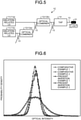
- a laser apparatus 1C includes, as illustrated in FIG. 5 , two ablation-related LDs 11a and 11b, two optical combiners 12a and 12b, optical fibers 13 arranged between the ablation-related LDs 11a and 11b and the optical combiners 12a and 12b, and an asymmetric tap coupler 14.
- the configurations of the ablation-related LDs 11, the optical combiners 12, the optical fibers 13, and the optical output section 21, illustrated in FIG. 4 are the same as those of the first embodiment described above.
- the ablation-related LD 11a is connected to the input side of the optical combiner 12b via an optical fiber 13. Further, the ablation-related LD 11b is connected to the input side of the optical combiner 12a via an optical fiber 13. Further, the output side of the optical combiner 12a is connected to the input side of the optical combiner 12b via an optical fiber 13. Further, the output side of the optical combiner 12b is connected to the input side of the asymmetric tap coupler 14 via an optical fiber 13.
- the output side of the asymmetric tap coupler 14 is connected to the optical output section 21 via an optical fiber 13.
- the optical combiner 12b arranged in the rearmost stage is provided with the asymmetric tap coupler 14.
- the composition ratio of the asymmetric tap coupler 14 can be set to, for example, 99:1, 95:5, 90:10, 75:25, etc. Further, in the asymmetric tap coupler 14 illustrated in FIG. 5 , the ratio of input ports to output ports is 2:1, but the ratio of input ports to output ports may be set to 1:2 or 2:2.
- a light source such as a monitor-related PD or the like, which outputs a wavelength different from those of the ablation-related LDs 11, may be connected thereto.
- the laser apparatus 1C configured as described above, since the plurality of optical combiners 12a and 12b are connected in a cascade state, it is possible to improve the laser light flatness without requiring a large space. Further, in the laser apparatus 1C, since the asymmetric tap coupler 14 is connected to the optical combiner 12b in the rearmost stage, the higher-order mode light excited by the optical combiner 12b is removed by the asymmetric tap coupler 14, and a ring beam is formed from the position of the tap port. Consequently, the light at the main port can be rid of higher-order mode light at a rate depending on the composition ratio, so it is possible to further improve the flatness.
- the full width at half maximum of a laser light decreases in the order of Nos. 4, 1, 2, and 3. Specifically, when the number of optical combiners is zero to two, as the number of optical combiners is larger, the full width at half maximum is smaller and the flatness is higher. On the other hand, when the number of optical combiners is three, the full width at half maximum is smaller than that of when the number of optical combiners is zero. This is because the optical combiner has a mode converter function that excites a higher-order mode light, and, when the number of optical combiners exceeds a certain level, the ratio of higher-order mode lights is increased and the flatness is deteriorated.
- the number of optical combiners that deteriorates the flatness also depends on the characteristics of the optical combiners.
- the optical intensity maximum value of a laser light decreases in the order of Nos. 1, 2, 3, and 4, that is, the value is smaller as the number of optical combiners is larger.
- connection method of ablation-related LDs and the number of optical combiners with the laser light flatness and intensity in a laser apparatus in which the optical combiners are connected in a cascade state, with reference to Table 2.
- Table 2 No. LD connection method Number of optical combiners Full width at half maximum Optical intensity maximum value 5 - 0 1.19 8.51 6 Parallel connection 1 1.15 8.34 7 Parallel connection 2 1.12 8.00 8 Individual connection 2 1.09 8.05 9 Parallel connection 3 1.38 7.75 10 Individual connection 3 0.983 7.82
- Nos. 5 to 10 in Table 2 represent the following configurations, respectively.
- No. 5 represents a configuration in which only one ablation-related LD is arranged and no optical combiner is included.
- No. 6 represents a configuration in which two ablation-related LDs are connected to one optical combiner.
- No. 7 represents the configuration of FIG. 3 .
- No. 8 represents the configuration of FIG. 1 .
- No. 9 represents the configuration of FIG. 4 .
- No. 10 represents a configuration in which the ablation-related LDs 11b are individually connected to the respective input sides of the optical combiners 12b in FIG. 4 .
- the full width at half maximum of a laser light decreases in the order of Nos. 9, 5, 6, 7, 8, and 10.
- the configuration in which the number of continuous connection stages of optical combiners is three and the ablation-related LDs are individually connected to the respective input sides of the optical combiners in the first stage and the second stage, is the smallest in the full width at half maximum and thus is the highest in the flatness.
- the optical intensity maximum value of a laser light decreases in the order of Nos. 5, 6, 8, 7, 10, and 9.
- the configuration in which the number of continuous connection stages of optical combiners is three and the two ablation-related LDs are connected to the input side of the optical combiner in the first stage, is the smallest in the optical intensity.
- FIGS. 6 and 7 an explanation will be given of the relationship of the positions of ablation-related LDs and the number of optical combiners with the laser light flatness in a laser apparatus in which the optical combiners are connected in a cascade state, with reference to FIGS. 6 and 7 .
- the optical intensity maps of laser lights emitted from laser apparatuses with a plurality of configurations, were created, and the optical intensity data of the respective pixels of these optical intensity maps were combined to form a histogram, by which the graph illustrated in FIGS. 6 and 7 were created.
- the horizontal axis indicates the optical intensity of a laser light
- the vertical axis indicates the probability density of having the optical intensity indicated on the horizontal axis. Therefore, in FIGS. 6 and 7 , the laser light flatness becomes higher as the graph stands more upright, and the laser light flatness becomes lower as the graph is flatter.
- the comparative examples 1 and 2 and the present invention examples 1 to 4 in FIGS. 6 and 7 represent the following configurations, respectively.
- the comparative example 1 represents a configuration in which only one ablation-related LD is arranged and no optical combiner is included.
- the comparative example 2 represents a configuration in which two ablation-related LDs are connected to one optical combiner.
- the present invention example 1 represents the configuration of FIG. 3 .
- the present invention example 2 represents the configuration of FIG. 4 .
- the present invention example 3 represents the configuration of FIG. 1 .
- the present invention example 4 represents the configuration of FIG. 5 .
- the present invention example 4 which includes two optical combiners and an asymmetric tap coupler connected to the optical combiner in the rearmost stage, is the highest in the flatness.
- the number of optical combiners 12 connected in a cascade state is three (see FIG. 4 ).
- the number of optical combiners 12 may be set to four or more.
- the explanations have been given on the assumption that the laser apparatus 1, 1A, 1B, or 1C is used for a medical catheter or the like, but the application of the laser apparatus 1, 1A, 1B, or 1C is not limited to the medical use.
- the present invention is suitable for the application to a laser apparatus that provides a medical treatment by irradiating a target area, such as an affected area, with a laser light from the tip of an optical fiber inside a catheter.
Landscapes
- Physics & Mathematics (AREA)
- Optics & Photonics (AREA)
- Electromagnetism (AREA)
- General Physics & Mathematics (AREA)
- Condensed Matter Physics & Semiconductors (AREA)
- Health & Medical Sciences (AREA)
- Surgery (AREA)
- Life Sciences & Earth Sciences (AREA)
- Engineering & Computer Science (AREA)
- Otolaryngology (AREA)
- Nuclear Medicine, Radiotherapy & Molecular Imaging (AREA)
- Biomedical Technology (AREA)
- Heart & Thoracic Surgery (AREA)
- Medical Informatics (AREA)
- Molecular Biology (AREA)
- Animal Behavior & Ethology (AREA)
- General Health & Medical Sciences (AREA)
- Public Health (AREA)
- Veterinary Medicine (AREA)
- Optical Couplings Of Light Guides (AREA)
- Semiconductor Lasers (AREA)
Abstract
Description
- The present invention relates to a laser apparatus.
- There is a known laser apparatus for providing a medical treatment by inserting a catheter into the patient's body and irradiating a target area, such as an affected area, with a laser light from the tip of an optical fiber inside the catheter. In such ablation by a laser light, there is a case where a beam of a laser light high in flatness of the beam profile is used, other than Gaussian light. Note that, hereinafter, the flatness of the beam profile of a laser light will be simply referred to as "laser light flatness".
- As a technique for improving such laser light flatness, for example,
Patent Literature 1 discloses a configuration that improves the laser light flatness by inputting lights guided through a plurality of optical waveguides into the incident end of an optical transmitter, and transmitting the lights while confining the lights in the optical transmission region of the optical transmitter. - In addition, Patent Literature 2 discloses a configuration for converting a Gaussian beam at a multi-mode optical fiber output into a flat top beam. Further,
- Patent Literature 3 discloses a configuration equipped with a beam shaping optical element that redistributes the light emitted by a high-brightness light source into an emission optical beam having a far-field beam sectional profile with a spatially flat optical intensity distribution.
-
- Patent Literature 1:
Japanese Laid-open Patent Publication No. 2005-15722 - Patent Literature 2:
Japanese Translation of PCT International Application Publication No. 2018-534110 - Patent Literature 3:
Japanese Translation of PCT International Application Publication No. 2018-521478 - However, the configuration disclosed in each of
Patent Literatures 1 to 3 entails problems in that, for example, the configuration cannot be used in a thin tube, such as a medical catheter or the like, because the apparatus configuration is complicated or requires a large placement space. - The present invention has been made in consideration of the above, and has an object to provide a laser apparatus that is excellent in space saving property and can improve the laser light flatness.
- To address the above problem and attain the object, a laser apparatus according to an embodiment of the present invention includes: one or more laser diodes and two or more optical combiners. Further, an output side of the laser diodes is connected to an input side of one of the optical combiners, and an output side of the one of the optical combiners is connected to an input side of another optical combiner.
- In the laser apparatus according to an embodiment of the present invention, the optical combiners include an input/output provided with a multi-mode optical fiber.
- In the laser apparatus according to an embodiment of the present invention, the optical combiners are a 2:1 optical combiner.
- In the laser apparatus according to an embodiment of the present invention, the optical combiners include two optical combiners, of which an output side of a first optical combiner is connected to an input side of a second optical combiner.
- In the laser apparatus according to an embodiment of the present invention, the optical combiners include three optical combiners, of which an output side of a first optical combiner is connected to an input side of a second optical combiner, and an output side of the second optical combiner is connected to an input side of a third optical combiner.
- In the laser apparatus according to an embodiment of the present invention, the laser diodes includes an output provided with a multi-mode optical fiber.
- In the laser apparatus according to an embodiment of the present invention, the laser diodes include two or more laser diodes, in which the laser diodes are individually connected to input sides of separate optical combiners.
- In the laser apparatus according to an embodiment of the present invention, a number of the laser diodes is smaller than the total number of input ports of the optical combiners.
- The laser apparatus according to an embodiment of the present invention includes an asymmetric tap coupler. Further, an input side of the asymmetric tap coupler is connected to an output side of one of the optical combiners arranged in a rearmost stage.
- According to the present invention, it is possible to improve the laser light flatness without requiring a large space, by connecting a plurality of optical combiners in a cascade state.
-
-
FIG. 1 is a schematic diagram illustrating the configuration of a laser apparatus according to a first embodiment of the present invention. -
FIG. 2 is an explanatory diagram for explaining the efficiency in a case where optical combiners are connected in a plurality of stages. -
FIG. 3 is a schematic diagram illustrating the configuration of a laser apparatus according to a second embodiment of the present invention. -
FIG. 4 is a schematic diagram illustrating the configuration of a laser apparatus according to a third embodiment of the present invention. -
FIG. 5 is a schematic diagram illustrating the configuration of a laser apparatus according to a fourth embodiment of the present invention. -
FIG. 6 is a graph for explaining the relationship of the number of ablation-related laser diodes and the number of optical combiners with the laser light flatness in a laser apparatus with the optical combiners connected in a cascade state, according to working examples of the present invention. -
FIG. 7 is a graph for explaining the relationship of the number of ablation-related laser diodes and the number of optical combiners with the laser light flatness in a laser apparatus with the optical combiners connected in a cascade state, according to working examples of the present invention. - A laser apparatus according to the present invention will be explained below with reference to the accompanying drawings. Note that the present invention is not limited to the following embodiments. Further, the constituent elements in the following embodiments encompass those which can be easily used as replacements by a person skilled in the art, or which are substantially equivalent thereto.
- A laser apparatus according to the present invention is characterized in that the laser apparatus includes one or more ablation-related laser diodes (each of which will be referred to as "ablation-related LD", hereinafter) and two or more optical combiners, and that the optical combiners are connected to each other in series (cascade connection). Hereinafter, explanations will be given of embodiments of a laser apparatus according to the present invention, with reference to
FIGS. 1 to 5 . - A
laser apparatus 1 according to this embodiment includes, as illustrated inFIG. 1 , two ablation-related LDs optical combiners optical fibers 13 arranged between the ablation-related LDs optical combiners related LDs 11" when being collectively referred to, and the plurality of optical combiners are expressed as "optical combiners 12", when being collectively referred to. - When the
laser apparatus 1 is used for a laser medical treatment by a medical catheter, the ablation-related light output from each ablation-related LD 11 is a light in a wavelength bandwidth, which is the so-called "living window", that is, a light in a wavelength bandwidth of 600 nm to 1,500 nm. Further, the output of each ablation-related LD 11 is set to 0.1 W or more, for example. Here, the respective ablation-related LDs 11 may be connected to each other, for example, in series, and may be configured to be supplied with a common current from the same power supply, or may be configured to be supplied with different currents from separate power supplies. In this respect, when the ablation-related LDs 11 are supplied with currents from separate power supplies, there is an advantage that the mixing ratio of the laser lights from the respective ablation-related LDs 11 can be changed. - The ablation-
related LD 11a is connected to the input side of theoptical combiner 12b via anoptical fiber 13. Further, the ablation-related LD 11b is connected to the input side of theoptical combiner 12a via anoptical fiber 13. Theoptical fiber 13 used as the output port of each ablation-related LD 11 is formed of a multi-mode optical fiber or single-mode optical fiber. Here, the length of theoptical fiber 13 is about 1 m, for example. - Now, as illustrated in
FIG. 2 , when a plurality ofoptical combiners 12 are connected in a cascade state, as the number of stages of this cascade connection is larger, the efficiency (the power of the laser light) becomes lower. Therefore, as illustrated inFIG. 1 , the two ablation-related LDs 11 are individually connected to the separateoptical combiners 12, and, further, the number of ablation-related LDs 11 connected to eachoptical combiner 12 is minimized, by which the decrease in the efficiency can be suppressed. Further, when the two ablation-related LDs 11 are individually connected to the separateoptical combiners 12, lights that have been made different in propagation mode type are mixed by theoptical combiner 12 in the subsequent stage, and the laser light flatness is thereby improved. - The number of ablation-
related LDs 11 is preferably smaller than the total number of input ports of theoptical combiners 12. In other words, theoptical combiners 12 preferably include one or more input ports to which no ablation-related LD 11 is connected. Here, the "input port" means a port other than the port connected to anotheroptical combiner 12 among the ports on the input side of eachoptical combiner 12. Thelaser apparatus 1 illustrated inFIG. 1 is configured such that the number of ablation-related LDs 11 is two, and the total number of input ports of theoptical combiners 12 is three. - Each of the
optical combiners 12 serves to multiplex (synthesize) a plurality of lights. Each of theoptical fibers 13 used as the input port and the output port of eachoptical combiner 12 is formed of a multi-mode optical fiber. Thisoptical fiber 13 has, for example, a core diameter of 105 µm and a clad diameter of 125 µm, and is composed of a step-index type optical fiber including a coating, such as an acrylate coating film or polyimide coating film. - Each of the
optical combiners 12 is an N:1 optical combiner, and preferably a 2:1 optical combiner. Further, eachoptical combiner 12 is a combiner of an end couple type or side couple type. Further, the respectiveoptical combiners 12 are mounted on the same plate made of a metal. This metal plate also functions as a heat dissipation plate. - The output side of the
optical combiner 12a is connected to the input side of theoptical combiner 12b via anoptical fiber 13. Further, the output side of theoptical combiner 12b is connected to an optical output section 21 via anoptical fiber 13. Here, as regards the vacant port of theoptical combiner 12a to which no ablation-relatedLD 11 is connected, a light source (for example, a monitor-related LD or the like) other than the ablation-relatedLDs 11 may be connected thereto. - As described above, when the plurality of
optical combiners 12 are connected in a cascade state, as the number of stages of this cascade connection is larger, the efficiency (the power of the laser light) becomes lower. Therefore, as illustrated inFIG. 1 , the number of continuous connection stages of theoptical combiners 12 is set to be not more than two, by which the decrease in the efficiency can be suppressed as much as possible. Further, there is a case where theoptical combiner 12 connected to the subsequent stage generates heat as the efficiency decreases. Therefore, theoptical combiner 12b, which is in the subsequent stage, of theoptical combiners - The optical output section 21 serves to output the light multiplexed by the
optical combiner 12b. The specific configuration of the optical output section 21 depends on the application of thelaser apparatus 1. For example, when thelaser apparatus 1 is used for a laser medical treatment by a medical catheter, the optical output section 21 is composed of an optical probe or the like. - In the
laser apparatus 1 configured as described above, since the plurality ofoptical combiners laser apparatus 1, since the two ablation-relatedLDs optical combiners optical combiner 12b in the subsequent stage, so it is possible to improve the laser light flatness. - In addition, for example, in the configuration disclosed in Patent Literature 2 mentioned above, it is necessary to use an optical fiber with a length of 5 m or more in order to convert the mode of a laser light. However, in the
laser apparatus 1 according to this embodiment, since the mode of laser light is converted by theoptical combiners 12, it is not necessary to elongate theoptical fibers 13. Therefore, thelaser apparatus 1 can achieve space saving more than the configuration disclosed in Patent Literature 2. - A
laser apparatus 1A according to this embodiment includes, as illustrated inFIG. 3 , two ablation-relatedLDs optical combiners optical fibers 13 arranged between the ablation-relatedLDs optical combiners LDs 11, theoptical combiners 12, theoptical fibers 13, and the optical output section 21, illustrated inFIG. 3 , are the same as those of the first embodiment described above. - The ablation-related
LDs optical combiner 12a viaoptical fibers 13. Further, the output side of theoptical combiner 12a is connected to the input side of theoptical combiner 12b via anoptical fiber 13. Further, the output side of theoptical combiner 12b is connected to the optical output section 21 via anoptical fiber 13. In this way, in thelaser apparatus 1A according to this embodiment, the two ablation-relatedLDs optical combiner 12a, and no ablation-relatedLD 11 is connected to theoptical combiner 12b arranged in the second stage. - In the
laser apparatus 1A configured as described above, since the plurality ofoptical combiners - A
laser apparatus 1B according to this embodiment includes, as illustrated inFIG. 4 , two ablation-relatedLDs optical combiners optical fibers 13 arranged between the ablation-relatedLDs optical combiners LDs 11, theoptical combiners 12, theoptical fibers 13, and the optical output section 21, illustrated inFIG. 4 , are the same as those of the first embodiment described above. - The ablation-related
LDs optical combiner 12a viaoptical fibers 13. Further, the output side of theoptical combiner 12a is connected to the input side of theoptical combiner 12b via anoptical fiber 13. Further, the output side of theoptical combiner 12b is connected to the input side of theoptical combiner 12c via anoptical fiber 13. Further, the output side of theoptical combiner 12c is connected to the optical output section 21 via anoptical fiber 13. In this way, in thelaser apparatus 1B according to this embodiment, the number of continuous connection stages of theoptical combiners 12 is three. - In the
laser apparatus 1B configured as described above, since the plurality ofoptical combiners laser apparatus 1B, since the number of continuous connection stages of theoptical combiners 12 is three, higher-order modes can be excited at the respectiveoptical combiners 12. Therefore, as compared to a case where the number of continuous connection stages of theoptical combiners 12 is set to two or less, it is possible to obtain a laser light with more higher-order modes. - A
laser apparatus 1C according to this embodiment includes, as illustrated inFIG. 5 , two ablation-relatedLDs optical combiners optical fibers 13 arranged between the ablation-relatedLDs optical combiners LDs 11, theoptical combiners 12, theoptical fibers 13, and the optical output section 21, illustrated inFIG. 4 , are the same as those of the first embodiment described above. - The ablation-related
LD 11a is connected to the input side of theoptical combiner 12b via anoptical fiber 13. Further, the ablation-relatedLD 11b is connected to the input side of theoptical combiner 12a via anoptical fiber 13. Further, the output side of theoptical combiner 12a is connected to the input side of theoptical combiner 12b via anoptical fiber 13. Further, the output side of theoptical combiner 12b is connected to the input side of the asymmetric tap coupler 14 via anoptical fiber 13. - Further, the output side of the asymmetric tap coupler 14 is connected to the optical output section 21 via an
optical fiber 13. In this way, in thelaser apparatus 1C according to this embodiment, theoptical combiner 12b arranged in the rearmost stage is provided with the asymmetric tap coupler 14. - The composition ratio of the asymmetric tap coupler 14 can be set to, for example, 99:1, 95:5, 90:10, 75:25, etc. Further, in the asymmetric tap coupler 14 illustrated in
FIG. 5 , the ratio of input ports to output ports is 2:1, but the ratio of input ports to output ports may be set to 1:2 or 2:2. Here, as regards the vacant port of the asymmetric tap coupler 14, for example, a light source, such as a monitor-related PD or the like, which outputs a wavelength different from those of the ablation-relatedLDs 11, may be connected thereto. - In the
laser apparatus 1C configured as described above, since the plurality ofoptical combiners laser apparatus 1C, since the asymmetric tap coupler 14 is connected to theoptical combiner 12b in the rearmost stage, the higher-order mode light excited by theoptical combiner 12b is removed by the asymmetric tap coupler 14, and a ring beam is formed from the position of the tap port. Consequently, the light at the main port can be rid of higher-order mode light at a rate depending on the composition ratio, so it is possible to further improve the flatness. - Hereinafter, the present invention will be described more specifically by taking working examples. First, an explanation will be given of the relationship of the number of optical combiners with the laser light flatness and intensity in a laser apparatus in which the optical combiners are connected in a cascade state, with reference to Table 1. Here, in general, as the full width at half maximum in the intensity distribution in the beam profile (which will be simply referred to as "full width at half maximum", hereinafter) of a laser light is smaller, the flatness tends to be higher. Therefore, in the following explanation, the full width at half maximum is used as an index to judge the laser light flatness.
Table 1 No. Number of optical combiners Full width at half maximum Optical intensity maximum value 1 0 1.19 8.51 2 1 1.15 8.34 3 2 1.12 8.00 4 3 1.38 7.75 - As illustrated in Table 1, the full width at half maximum of a laser light decreases in the order of Nos. 4, 1, 2, and 3. Specifically, when the number of optical combiners is zero to two, as the number of optical combiners is larger, the full width at half maximum is smaller and the flatness is higher. On the other hand, when the number of optical combiners is three, the full width at half maximum is smaller than that of when the number of optical combiners is zero. This is because the optical combiner has a mode converter function that excites a higher-order mode light, and, when the number of optical combiners exceeds a certain level, the ratio of higher-order mode lights is increased and the flatness is deteriorated. Here, the number of optical combiners that deteriorates the flatness also depends on the characteristics of the optical combiners.
- Further, as illustrated in Table 1, the optical intensity maximum value of a laser light decreases in the order of Nos. 1, 2, 3, and 4, that is, the value is smaller as the number of optical combiners is larger.
- Next, an explanation will be given of the relationship of the connection method of ablation-related LDs and the number of optical combiners with the laser light flatness and intensity in a laser apparatus in which the optical combiners are connected in a cascade state, with reference to Table 2.
Table 2 No. LD connection method Number of optical combiners Full width at half maximum Optical intensity maximum value 5 - 0 1.19 8.51 6 Parallel connection 1 1.15 8.34 7 Parallel connection 2 1.12 8.00 8 Individual connection 2 1.09 8.05 9 Parallel connection 3 1.38 7.75 10 Individual connection 3 0.983 7.82 - Here, Nos. 5 to 10 in Table 2 represent the following configurations, respectively.
- No. 5 represents a configuration in which only one ablation-related LD is arranged and no optical combiner is included.
- No. 6 represents a configuration in which two ablation-related LDs are connected to one optical combiner.
- No. 7 represents the configuration of
FIG. 3 . - No. 8 represents the configuration of
FIG. 1 . - No. 9 represents the configuration of
FIG. 4 . - No. 10 represents a configuration in which the ablation-related
LDs 11b are individually connected to the respective input sides of theoptical combiners 12b inFIG. 4 . - As illustrated in Table 2, the full width at half maximum of a laser light decreases in the order of Nos. 9, 5, 6, 7, 8, and 10. Specifically, the configuration, in which the number of continuous connection stages of optical combiners is three and the ablation-related LDs are individually connected to the respective input sides of the optical combiners in the first stage and the second stage, is the smallest in the full width at half maximum and thus is the highest in the flatness.
- Further, as illustrated in Table 2, the optical intensity maximum value of a laser light decreases in the order of Nos. 5, 6, 8, 7, 10, and 9. Specifically, the configuration (see
FIG. 4 ), in which the number of continuous connection stages of optical combiners is three and the two ablation-related LDs are connected to the input side of the optical combiner in the first stage, is the smallest in the optical intensity. - Next, an explanation will be given of the relationship of the positions of ablation-related LDs and the number of optical combiners with the laser light flatness in a laser apparatus in which the optical combiners are connected in a cascade state, with reference to
FIGS. 6 and7 . In these working examples, the optical intensity maps of laser lights, emitted from laser apparatuses with a plurality of configurations, were created, and the optical intensity data of the respective pixels of these optical intensity maps were combined to form a histogram, by which the graph illustrated inFIGS. 6 and7 were created. InFIGS. 6 and7 , the horizontal axis indicates the optical intensity of a laser light, and the vertical axis indicates the probability density of having the optical intensity indicated on the horizontal axis. Therefore, inFIGS. 6 and7 , the laser light flatness becomes higher as the graph stands more upright, and the laser light flatness becomes lower as the graph is flatter. - Here, the comparative examples 1 and 2 and the present invention examples 1 to 4 in
FIGS. 6 and7 represent the following configurations, respectively. - The comparative example 1 represents a configuration in which only one ablation-related LD is arranged and no optical combiner is included.
- The comparative example 2 represents a configuration in which two ablation-related LDs are connected to one optical combiner.
- The present invention example 1 represents the configuration of
FIG. 3 . - The present invention example 2 represents the configuration of
FIG. 4 . - The present invention example 3 represents the configuration of
FIG. 1 . - The present invention example 4 represents the configuration of
FIG. 5 . - As illustrated in
FIGS. 6 and7 , by comparing the comparative example 1 including no optical combiner with the comparative example 2 and the present invention examples 1 to 4 each of which includes an optical combiner, it can be seen that the flatness of the latter examples is higher. Further, by comparing the comparative example 2 including one optical combiner with the present invention examples 1, 3, and 4 each of which includes two optical combiners, it can be seen that the flatness of the latter examples is higher. Further, by comparing the present invention examples 1, 3, and 4 each of which includes two optical combiners with the present invention example 2 including three optical combiners, it can be seen that the flatness of the former examples is higher. Further, by comparing the comparative examples 1 and 2 with the present invention examples 1 to 4, it can be seen that the present invention example 4, which includes two optical combiners and an asymmetric tap coupler connected to the optical combiner in the rearmost stage, is the highest in the flatness. - In the above descriptions, the laser apparatus according to each of the embodiments of the present invention has been specifically explained in the form for implementing the invention and by taking working examples. However, the gist of the present invention is not limited to these descriptions, and should be broadly interpreted on the basis of the scope of the claims. Further, it goes without saying that various changes, modifications, and so forth based on these descriptions are also included in the gist of the present invention.
- For example, in the third embodiment described above, an explanation has been given of the configuration in which the number of
optical combiners 12 connected in a cascade state is three (seeFIG. 4 ). However, in order to obtain a laser light with more higher-order modes, the number ofoptical combiners 12 may be set to four or more. - Further, in the embodiments described above, the explanations have been given on the assumption that the
laser apparatus laser apparatus - The present invention is suitable for the application to a laser apparatus that provides a medical treatment by irradiating a target area, such as an affected area, with a laser light from the tip of an optical fiber inside a catheter.
-
- 1, 1A, 1B, 1C Laser apparatus
- 11, 11a, 11b Ablation-related LD
- 12, 12a, 12b, 12c Optical combiner
- 13 Optical fiber
- 14 Asymmetric tap coupler
- 21 Optical output section
Claims (9)
- A laser apparatus comprising:one or more laser diodes and two or more optical combiners, whereinan output side of the laser diodes is connected to an input side of one of the optical combiners, andan output side of the one of the optical combiners is connected to an input side of another optical combiner.
- The laser apparatus according to claim 1, wherein the optical combiners include an input/output provided with a multi-mode optical fiber.
- The laser apparatus according to claim 1 or 2, wherein the optical combiners are a 2:1 optical combiner.
- The laser apparatus according to any one of claims 1 to 3, wherein the optical combiners include two optical combiners, of which
an output side of a first optical combiner is connected to an input side of a second optical combiner. - The laser apparatus according to any one of claims 1 to 3, wherein the optical combiners include three optical combiners, of whichan output side of a first optical combiner is connected to an input side of a second optical combiner, andan output side of the second optical combiner is connected to an input side of a third optical combiner.
- The laser apparatus according to any one of claims 1 to 5, wherein the laser diodes includes an output provided with a multi-mode optical fiber.
- The laser apparatus according to any one of claims 1 to 6, wherein the laser diodes include two or more laser diodes, in which
the laser diodes are individually connected to input sides of separate optical combiners. - The laser apparatus according to any one of claims 1 to 7, wherein a number of the laser diodes is smaller than the total number of input ports of the optical combiners.
- The laser apparatus according to any one of claims 1 to 8, comprising an asymmetric tap coupler, wherein
an input side of the asymmetric tap coupler is connected to an output side of one of the optical combiners arranged in a rearmost stage.
Applications Claiming Priority (2)
| Application Number | Priority Date | Filing Date | Title |
|---|---|---|---|
| JP2019060396A JP7203658B2 (en) | 2019-03-27 | 2019-03-27 | laser device |
| PCT/JP2020/013017 WO2020196521A1 (en) | 2019-03-27 | 2020-03-24 | Laser device |
Publications (3)
| Publication Number | Publication Date |
|---|---|
| EP3952038A1 true EP3952038A1 (en) | 2022-02-09 |
| EP3952038A4 EP3952038A4 (en) | 2022-12-21 |
| EP3952038B1 EP3952038B1 (en) | 2024-05-01 |
Family
ID=72612017
Family Applications (1)
| Application Number | Title | Priority Date | Filing Date |
|---|---|---|---|
| EP20777511.5A Active EP3952038B1 (en) | 2019-03-27 | 2020-03-24 | Laser device |
Country Status (5)
| Country | Link |
|---|---|
| US (1) | US12184038B2 (en) |
| EP (1) | EP3952038B1 (en) |
| JP (1) | JP7203658B2 (en) |
| CN (1) | CN113615015B (en) |
| WO (1) | WO2020196521A1 (en) |
Families Citing this family (1)
| Publication number | Priority date | Publication date | Assignee | Title |
|---|---|---|---|---|
| WO2019230713A1 (en) * | 2018-06-01 | 2019-12-05 | 古河電気工業株式会社 | Detection system, catheter device, and laser cauterizing device |
Family Cites Families (22)
| Publication number | Priority date | Publication date | Assignee | Title |
|---|---|---|---|---|
| US4981138A (en) * | 1988-06-30 | 1991-01-01 | Yale University | Endoscopic fiberoptic fluorescence spectrometer |
| US6785440B1 (en) * | 1992-04-16 | 2004-08-31 | Coherent, Inc. | Assembly for focusing and coupling the radiation produced by a semiconductor laser into optical fibers |
| DE4238434A1 (en) * | 1992-04-16 | 1993-10-21 | Adlas Gmbh & Co Kg | Arrangement for bundling and coupling the radiation generated by a semiconductor laser into optical fibers |
| US6212310B1 (en) | 1996-10-22 | 2001-04-03 | Sdl, Inc. | High power fiber gain media system achieved through power scaling via multiplexing |
| JP4213402B2 (en) * | 2002-05-23 | 2009-01-21 | 富士フイルム株式会社 | Condensing lens, combined laser light source and exposure apparatus |
| JP2005015722A (en) | 2003-06-27 | 2005-01-20 | Gifu Prefecture | Wood / bamboo vinegar or its manufacturing method and its manufacturing equipment |
| US7376293B2 (en) | 2003-07-18 | 2008-05-20 | Network Intergrity Systems Inc. | Remote location of active section of fiber in a multimode intrusion detection system |
| US7403674B2 (en) | 2003-07-18 | 2008-07-22 | Network Integrity Systems Inc. | Intrusion detection system for a multimode optical fiber using a bulk optical wavelength division multiplexer for maintaining modal power distribution |
| KR101032222B1 (en) | 2003-07-18 | 2011-05-02 | 네트워크 인테그리티 시스템스 인코퍼레이티드 | Multimode Fiber Intrusion Detection System |
| US7403675B2 (en) | 2003-07-18 | 2008-07-22 | Network Integrity Systems Inc. | Method of high order mode excitation for multimode intrusion detection |
| JP2005157225A (en) | 2003-11-06 | 2005-06-16 | Sumitomo Electric Ind Ltd | Optical transmitter module |
| JP2007041342A (en) | 2005-08-04 | 2007-02-15 | Fujifilm Corp | Combined light source |
| DE102008052475A1 (en) | 2008-10-20 | 2010-04-29 | Raab, Volker, Dr. | A polarization |
| GB2490354A (en) | 2011-04-28 | 2012-10-31 | Univ Southampton | Laser with axially-symmetric beam profile |
| US10568692B2 (en) | 2012-11-09 | 2020-02-25 | Boston Scientific Scimed, Inc. | Surgical laser tool |
| US9560358B2 (en) | 2013-07-22 | 2017-01-31 | Qualcomm Incorporated | Device and method for scalable coding of video information |
| WO2017005604A1 (en) | 2015-07-07 | 2017-01-12 | Koninklijke Philips N.V. | Light emitting apparatus |
| ITUB20155092A1 (en) | 2015-11-02 | 2017-05-02 | Quanta System Spa | LASER SYSTEM FOR SELECTIVE ACNE TREATMENT |
| JPWO2017175391A1 (en) | 2016-04-08 | 2019-03-28 | オリンパス株式会社 | Illuminating device and endoscope provided with the same |
| US10261329B2 (en) | 2016-08-26 | 2019-04-16 | Nlight, Inc. | Fiber combiner with input port dump |
| US10522963B2 (en) | 2016-08-30 | 2019-12-31 | Corning Incorporated | Laser cutting of materials with intensity mapping optical system |
| WO2018140638A1 (en) | 2017-01-25 | 2018-08-02 | Lawrence Livermore National Security, Llc | System and method for laser system having non-planar thin disc gain media |
-
2019
- 2019-03-27 JP JP2019060396A patent/JP7203658B2/en active Active
-
2020
- 2020-03-24 EP EP20777511.5A patent/EP3952038B1/en active Active
- 2020-03-24 WO PCT/JP2020/013017 patent/WO2020196521A1/en not_active Ceased
- 2020-03-24 CN CN202080022691.9A patent/CN113615015B/en active Active
-
2021
- 2021-09-17 US US17/478,193 patent/US12184038B2/en active Active
Also Published As
| Publication number | Publication date |
|---|---|
| CN113615015A (en) | 2021-11-05 |
| JP7203658B2 (en) | 2023-01-13 |
| US20220006266A1 (en) | 2022-01-06 |
| CN113615015B (en) | 2024-04-30 |
| EP3952038B1 (en) | 2024-05-01 |
| JP2020160310A (en) | 2020-10-01 |
| US12184038B2 (en) | 2024-12-31 |
| EP3952038A4 (en) | 2022-12-21 |
| WO2020196521A1 (en) | 2020-10-01 |
Similar Documents
| Publication | Publication Date | Title |
|---|---|---|
| US7649914B2 (en) | Optical fibre laser | |
| EP2951625B1 (en) | Fibre optical laser combiner | |
| JP5738275B2 (en) | Fiber-based laser combiner | |
| US10620448B2 (en) | Speckle-free imaging light source based on random fiber laser using strong-coupling multi-core optical fiber | |
| WO2015182025A1 (en) | Illumination apparatus, method and medical imaging system | |
| US8983259B2 (en) | Multi-function beam delivery fibers and related system and method | |
| JP6348861B2 (en) | Optical transmission apparatus and optical transmission method | |
| CN114597762A (en) | A kind of blue light semiconductor laser beam combining device and high brightness blue light output method | |
| WO2022122016A1 (en) | Optical amplification apparatus and mode division multiplexing system comprising optical amplification apparatus | |
| CN1211700C (en) | Thulium doped optical fibre amplifier for raising conversion efficiency of S-bandwidth by pumping light | |
| EP3279556A1 (en) | Fiber optic light source | |
| US12184038B2 (en) | Laser apparatus | |
| CN105811229A (en) | Supercontinuum laser generating device | |
| US10892603B2 (en) | Arrayed waveguide grating beam combiner | |
| WO2021111103A1 (en) | Light source | |
| JP4032648B2 (en) | Optical fiber amplifier and optical fiber used therefor | |
| JPWO2020071262A1 (en) | Optical amplifier and optical amplifier method | |
| CN206059905U (en) | Semiconductor laser | |
| US20250098943A1 (en) | Beam-shaping lens, beam-shaping element, light source device for an endoscope, and endoscope | |
| US20240181099A1 (en) | Ultraviolet light irradiation system and ultraviolet light irradiation method | |
| CN209496171U (en) | WDM device | |
| CN223079549U (en) | Laser and high-brightness fiber laser processing equipment | |
| CN214957790U (en) | High-consistency multi-path light splitting amplification optical fiber laser amplifier | |
| WO2002073253A2 (en) | Fiber delivery system for laser diodes | |
| CN120511544B (en) | laser |
Legal Events
| Date | Code | Title | Description |
|---|---|---|---|
| STAA | Information on the status of an ep patent application or granted ep patent |
Free format text: STATUS: THE INTERNATIONAL PUBLICATION HAS BEEN MADE |
|
| PUAI | Public reference made under article 153(3) epc to a published international application that has entered the european phase |
Free format text: ORIGINAL CODE: 0009012 |
|
| STAA | Information on the status of an ep patent application or granted ep patent |
Free format text: STATUS: REQUEST FOR EXAMINATION WAS MADE |
|
| 17P | Request for examination filed |
Effective date: 20210922 |
|
| AK | Designated contracting states |
Kind code of ref document: A1 Designated state(s): AL AT BE BG CH CY CZ DE DK EE ES FI FR GB GR HR HU IE IS IT LI LT LU LV MC MK MT NL NO PL PT RO RS SE SI SK SM TR |
|
| DAV | Request for validation of the european patent (deleted) | ||
| DAX | Request for extension of the european patent (deleted) | ||
| A4 | Supplementary search report drawn up and despatched |
Effective date: 20221121 |
|
| RIC1 | Information provided on ipc code assigned before grant |
Ipc: A61B 18/22 20060101ALN20221115BHEP Ipc: A61B 18/20 20060101ALN20221115BHEP Ipc: A61B 18/00 20060101ALN20221115BHEP Ipc: H01S 5/02251 20210101ALN20221115BHEP Ipc: H01S 5/00 20060101ALI20221115BHEP Ipc: H01S 5/40 20060101ALI20221115BHEP Ipc: A61B 18/24 20060101AFI20221115BHEP |
|
| REG | Reference to a national code |
Ref country code: DE Ipc: H01S0005400000 Ref legal event code: R079 Ref document number: 602020030240 Country of ref document: DE Free format text: PREVIOUS MAIN CLASS: H01S0005022000 |
|
| GRAP | Despatch of communication of intention to grant a patent |
Free format text: ORIGINAL CODE: EPIDOSNIGR1 |
|
| STAA | Information on the status of an ep patent application or granted ep patent |
Free format text: STATUS: GRANT OF PATENT IS INTENDED |
|
| RIC1 | Information provided on ipc code assigned before grant |
Ipc: A61B 18/22 20060101ALN20231016BHEP Ipc: A61B 18/20 20060101ALN20231016BHEP Ipc: A61B 18/00 20060101ALN20231016BHEP Ipc: H01S 5/02251 20210101ALN20231016BHEP Ipc: A61B 18/24 20060101ALI20231016BHEP Ipc: H01S 5/0239 20210101ALI20231016BHEP Ipc: H01S 5/00 20060101ALI20231016BHEP Ipc: H01S 5/40 20060101AFI20231016BHEP |
|
| INTG | Intention to grant announced |
Effective date: 20231107 |
|
| GRAS | Grant fee paid |
Free format text: ORIGINAL CODE: EPIDOSNIGR3 |
|
| GRAA | (expected) grant |
Free format text: ORIGINAL CODE: 0009210 |
|
| STAA | Information on the status of an ep patent application or granted ep patent |
Free format text: STATUS: THE PATENT HAS BEEN GRANTED |
|
| P01 | Opt-out of the competence of the unified patent court (upc) registered |
Effective date: 20240306 |
|
| AK | Designated contracting states |
Kind code of ref document: B1 Designated state(s): AL AT BE BG CH CY CZ DE DK EE ES FI FR GB GR HR HU IE IS IT LI LT LU LV MC MK MT NL NO PL PT RO RS SE SI SK SM TR |
|
| REG | Reference to a national code |
Ref country code: GB Ref legal event code: FG4D |
|
| REG | Reference to a national code |
Ref country code: CH Ref legal event code: EP |
|
| REG | Reference to a national code |
Ref country code: IE Ref legal event code: FG4D |
|
| REG | Reference to a national code |
Ref country code: DE Ref legal event code: R096 Ref document number: 602020030240 Country of ref document: DE |
|
| REG | Reference to a national code |
Ref country code: LT Ref legal event code: MG9D |
|
| REG | Reference to a national code |
Ref country code: NL Ref legal event code: MP Effective date: 20240501 |
|
| PG25 | Lapsed in a contracting state [announced via postgrant information from national office to epo] |
Ref country code: IS Free format text: LAPSE BECAUSE OF FAILURE TO SUBMIT A TRANSLATION OF THE DESCRIPTION OR TO PAY THE FEE WITHIN THE PRESCRIBED TIME-LIMIT Effective date: 20240901 |
|
| PG25 | Lapsed in a contracting state [announced via postgrant information from national office to epo] |
Ref country code: BG Free format text: LAPSE BECAUSE OF FAILURE TO SUBMIT A TRANSLATION OF THE DESCRIPTION OR TO PAY THE FEE WITHIN THE PRESCRIBED TIME-LIMIT Effective date: 20240501 |
|
| PG25 | Lapsed in a contracting state [announced via postgrant information from national office to epo] |
Ref country code: FI Free format text: LAPSE BECAUSE OF FAILURE TO SUBMIT A TRANSLATION OF THE DESCRIPTION OR TO PAY THE FEE WITHIN THE PRESCRIBED TIME-LIMIT Effective date: 20240501 Ref country code: HR Free format text: LAPSE BECAUSE OF FAILURE TO SUBMIT A TRANSLATION OF THE DESCRIPTION OR TO PAY THE FEE WITHIN THE PRESCRIBED TIME-LIMIT Effective date: 20240501 |
|
| PG25 | Lapsed in a contracting state [announced via postgrant information from national office to epo] |
Ref country code: GR Free format text: LAPSE BECAUSE OF FAILURE TO SUBMIT A TRANSLATION OF THE DESCRIPTION OR TO PAY THE FEE WITHIN THE PRESCRIBED TIME-LIMIT Effective date: 20240802 |
|
| PG25 | Lapsed in a contracting state [announced via postgrant information from national office to epo] |
Ref country code: PT Free format text: LAPSE BECAUSE OF FAILURE TO SUBMIT A TRANSLATION OF THE DESCRIPTION OR TO PAY THE FEE WITHIN THE PRESCRIBED TIME-LIMIT Effective date: 20240902 |
|
| REG | Reference to a national code |
Ref country code: AT Ref legal event code: MK05 Ref document number: 1683727 Country of ref document: AT Kind code of ref document: T Effective date: 20240501 |
|
| PG25 | Lapsed in a contracting state [announced via postgrant information from national office to epo] |
Ref country code: NL Free format text: LAPSE BECAUSE OF FAILURE TO SUBMIT A TRANSLATION OF THE DESCRIPTION OR TO PAY THE FEE WITHIN THE PRESCRIBED TIME-LIMIT Effective date: 20240501 |
|
| PG25 | Lapsed in a contracting state [announced via postgrant information from national office to epo] |
Ref country code: ES Free format text: LAPSE BECAUSE OF FAILURE TO SUBMIT A TRANSLATION OF THE DESCRIPTION OR TO PAY THE FEE WITHIN THE PRESCRIBED TIME-LIMIT Effective date: 20240501 |
|
| PG25 | Lapsed in a contracting state [announced via postgrant information from national office to epo] |
Ref country code: AT Free format text: LAPSE BECAUSE OF FAILURE TO SUBMIT A TRANSLATION OF THE DESCRIPTION OR TO PAY THE FEE WITHIN THE PRESCRIBED TIME-LIMIT Effective date: 20240501 |
|
| PG25 | Lapsed in a contracting state [announced via postgrant information from national office to epo] |
Ref country code: PL Free format text: LAPSE BECAUSE OF FAILURE TO SUBMIT A TRANSLATION OF THE DESCRIPTION OR TO PAY THE FEE WITHIN THE PRESCRIBED TIME-LIMIT Effective date: 20240501 |
|
| PG25 | Lapsed in a contracting state [announced via postgrant information from national office to epo] |
Ref country code: LV Free format text: LAPSE BECAUSE OF FAILURE TO SUBMIT A TRANSLATION OF THE DESCRIPTION OR TO PAY THE FEE WITHIN THE PRESCRIBED TIME-LIMIT Effective date: 20240501 |
|
| PG25 | Lapsed in a contracting state [announced via postgrant information from national office to epo] |
Ref country code: PT Free format text: LAPSE BECAUSE OF FAILURE TO SUBMIT A TRANSLATION OF THE DESCRIPTION OR TO PAY THE FEE WITHIN THE PRESCRIBED TIME-LIMIT Effective date: 20240902 Ref country code: PL Free format text: LAPSE BECAUSE OF FAILURE TO SUBMIT A TRANSLATION OF THE DESCRIPTION OR TO PAY THE FEE WITHIN THE PRESCRIBED TIME-LIMIT Effective date: 20240501 Ref country code: NO Free format text: LAPSE BECAUSE OF FAILURE TO SUBMIT A TRANSLATION OF THE DESCRIPTION OR TO PAY THE FEE WITHIN THE PRESCRIBED TIME-LIMIT Effective date: 20240801 Ref country code: NL Free format text: LAPSE BECAUSE OF FAILURE TO SUBMIT A TRANSLATION OF THE DESCRIPTION OR TO PAY THE FEE WITHIN THE PRESCRIBED TIME-LIMIT Effective date: 20240501 Ref country code: LV Free format text: LAPSE BECAUSE OF FAILURE TO SUBMIT A TRANSLATION OF THE DESCRIPTION OR TO PAY THE FEE WITHIN THE PRESCRIBED TIME-LIMIT Effective date: 20240501 Ref country code: IS Free format text: LAPSE BECAUSE OF FAILURE TO SUBMIT A TRANSLATION OF THE DESCRIPTION OR TO PAY THE FEE WITHIN THE PRESCRIBED TIME-LIMIT Effective date: 20240901 Ref country code: HR Free format text: LAPSE BECAUSE OF FAILURE TO SUBMIT A TRANSLATION OF THE DESCRIPTION OR TO PAY THE FEE WITHIN THE PRESCRIBED TIME-LIMIT Effective date: 20240501 Ref country code: GR Free format text: LAPSE BECAUSE OF FAILURE TO SUBMIT A TRANSLATION OF THE DESCRIPTION OR TO PAY THE FEE WITHIN THE PRESCRIBED TIME-LIMIT Effective date: 20240802 Ref country code: FI Free format text: LAPSE BECAUSE OF FAILURE TO SUBMIT A TRANSLATION OF THE DESCRIPTION OR TO PAY THE FEE WITHIN THE PRESCRIBED TIME-LIMIT Effective date: 20240501 Ref country code: ES Free format text: LAPSE BECAUSE OF FAILURE TO SUBMIT A TRANSLATION OF THE DESCRIPTION OR TO PAY THE FEE WITHIN THE PRESCRIBED TIME-LIMIT Effective date: 20240501 Ref country code: BG Free format text: LAPSE BECAUSE OF FAILURE TO SUBMIT A TRANSLATION OF THE DESCRIPTION OR TO PAY THE FEE WITHIN THE PRESCRIBED TIME-LIMIT Effective date: 20240501 Ref country code: AT Free format text: LAPSE BECAUSE OF FAILURE TO SUBMIT A TRANSLATION OF THE DESCRIPTION OR TO PAY THE FEE WITHIN THE PRESCRIBED TIME-LIMIT Effective date: 20240501 Ref country code: RS Free format text: LAPSE BECAUSE OF FAILURE TO SUBMIT A TRANSLATION OF THE DESCRIPTION OR TO PAY THE FEE WITHIN THE PRESCRIBED TIME-LIMIT Effective date: 20240801 |
|
| PG25 | Lapsed in a contracting state [announced via postgrant information from national office to epo] |
Ref country code: DK Free format text: LAPSE BECAUSE OF FAILURE TO SUBMIT A TRANSLATION OF THE DESCRIPTION OR TO PAY THE FEE WITHIN THE PRESCRIBED TIME-LIMIT Effective date: 20240501 |
|
| PG25 | Lapsed in a contracting state [announced via postgrant information from national office to epo] |
Ref country code: EE Free format text: LAPSE BECAUSE OF FAILURE TO SUBMIT A TRANSLATION OF THE DESCRIPTION OR TO PAY THE FEE WITHIN THE PRESCRIBED TIME-LIMIT Effective date: 20240501 |
|
| PG25 | Lapsed in a contracting state [announced via postgrant information from national office to epo] |
Ref country code: CZ Free format text: LAPSE BECAUSE OF FAILURE TO SUBMIT A TRANSLATION OF THE DESCRIPTION OR TO PAY THE FEE WITHIN THE PRESCRIBED TIME-LIMIT Effective date: 20240501 |
|
| PG25 | Lapsed in a contracting state [announced via postgrant information from national office to epo] |
Ref country code: RO Free format text: LAPSE BECAUSE OF FAILURE TO SUBMIT A TRANSLATION OF THE DESCRIPTION OR TO PAY THE FEE WITHIN THE PRESCRIBED TIME-LIMIT Effective date: 20240501 Ref country code: SK Free format text: LAPSE BECAUSE OF FAILURE TO SUBMIT A TRANSLATION OF THE DESCRIPTION OR TO PAY THE FEE WITHIN THE PRESCRIBED TIME-LIMIT Effective date: 20240501 |
|
| PG25 | Lapsed in a contracting state [announced via postgrant information from national office to epo] |
Ref country code: SM Free format text: LAPSE BECAUSE OF FAILURE TO SUBMIT A TRANSLATION OF THE DESCRIPTION OR TO PAY THE FEE WITHIN THE PRESCRIBED TIME-LIMIT Effective date: 20240501 |
|
| PG25 | Lapsed in a contracting state [announced via postgrant information from national office to epo] |
Ref country code: SM Free format text: LAPSE BECAUSE OF FAILURE TO SUBMIT A TRANSLATION OF THE DESCRIPTION OR TO PAY THE FEE WITHIN THE PRESCRIBED TIME-LIMIT Effective date: 20240501 Ref country code: SK Free format text: LAPSE BECAUSE OF FAILURE TO SUBMIT A TRANSLATION OF THE DESCRIPTION OR TO PAY THE FEE WITHIN THE PRESCRIBED TIME-LIMIT Effective date: 20240501 Ref country code: RO Free format text: LAPSE BECAUSE OF FAILURE TO SUBMIT A TRANSLATION OF THE DESCRIPTION OR TO PAY THE FEE WITHIN THE PRESCRIBED TIME-LIMIT Effective date: 20240501 Ref country code: EE Free format text: LAPSE BECAUSE OF FAILURE TO SUBMIT A TRANSLATION OF THE DESCRIPTION OR TO PAY THE FEE WITHIN THE PRESCRIBED TIME-LIMIT Effective date: 20240501 Ref country code: DK Free format text: LAPSE BECAUSE OF FAILURE TO SUBMIT A TRANSLATION OF THE DESCRIPTION OR TO PAY THE FEE WITHIN THE PRESCRIBED TIME-LIMIT Effective date: 20240501 Ref country code: CZ Free format text: LAPSE BECAUSE OF FAILURE TO SUBMIT A TRANSLATION OF THE DESCRIPTION OR TO PAY THE FEE WITHIN THE PRESCRIBED TIME-LIMIT Effective date: 20240501 |
|
| REG | Reference to a national code |
Ref country code: DE Ref legal event code: R097 Ref document number: 602020030240 Country of ref document: DE |
|
| PG25 | Lapsed in a contracting state [announced via postgrant information from national office to epo] |
Ref country code: IT Free format text: LAPSE BECAUSE OF FAILURE TO SUBMIT A TRANSLATION OF THE DESCRIPTION OR TO PAY THE FEE WITHIN THE PRESCRIBED TIME-LIMIT Effective date: 20240501 |
|
| PLBE | No opposition filed within time limit |
Free format text: ORIGINAL CODE: 0009261 |
|
| STAA | Information on the status of an ep patent application or granted ep patent |
Free format text: STATUS: NO OPPOSITION FILED WITHIN TIME LIMIT |
|
| 26N | No opposition filed |
Effective date: 20250204 |
|
| PG25 | Lapsed in a contracting state [announced via postgrant information from national office to epo] |
Ref country code: SI Free format text: LAPSE BECAUSE OF FAILURE TO SUBMIT A TRANSLATION OF THE DESCRIPTION OR TO PAY THE FEE WITHIN THE PRESCRIBED TIME-LIMIT Effective date: 20240501 |
|
| PG25 | Lapsed in a contracting state [announced via postgrant information from national office to epo] |
Ref country code: SE Free format text: LAPSE BECAUSE OF FAILURE TO SUBMIT A TRANSLATION OF THE DESCRIPTION OR TO PAY THE FEE WITHIN THE PRESCRIBED TIME-LIMIT Effective date: 20240501 |
|
| PG25 | Lapsed in a contracting state [announced via postgrant information from national office to epo] |
Ref country code: MC Free format text: LAPSE BECAUSE OF FAILURE TO SUBMIT A TRANSLATION OF THE DESCRIPTION OR TO PAY THE FEE WITHIN THE PRESCRIBED TIME-LIMIT Effective date: 20240501 |
|
| REG | Reference to a national code |
Ref country code: CH Ref legal event code: H13 Free format text: ST27 STATUS EVENT CODE: U-0-0-H10-H13 (AS PROVIDED BY THE NATIONAL OFFICE) Effective date: 20251023 |
|
| PG25 | Lapsed in a contracting state [announced via postgrant information from national office to epo] |
Ref country code: LU Free format text: LAPSE BECAUSE OF NON-PAYMENT OF DUE FEES Effective date: 20250324 |
|
| REG | Reference to a national code |
Ref country code: BE Ref legal event code: MM Effective date: 20250331 |
|
| PG25 | Lapsed in a contracting state [announced via postgrant information from national office to epo] |
Ref country code: FR Free format text: LAPSE BECAUSE OF NON-PAYMENT OF DUE FEES Effective date: 20250331 |
|
| PG25 | Lapsed in a contracting state [announced via postgrant information from national office to epo] |
Ref country code: BE Free format text: LAPSE BECAUSE OF NON-PAYMENT OF DUE FEES Effective date: 20250331 |
|
| PG25 | Lapsed in a contracting state [announced via postgrant information from national office to epo] |
Ref country code: CH Free format text: LAPSE BECAUSE OF NON-PAYMENT OF DUE FEES Effective date: 20250331 |
|
| PG25 | Lapsed in a contracting state [announced via postgrant information from national office to epo] |
Ref country code: IE Free format text: LAPSE BECAUSE OF NON-PAYMENT OF DUE FEES Effective date: 20250324 |
|
| PGFP | Annual fee paid to national office [announced via postgrant information from national office to epo] |
Ref country code: GB Payment date: 20260202 Year of fee payment: 7 |
|
| PGFP | Annual fee paid to national office [announced via postgrant information from national office to epo] |
Ref country code: DE Payment date: 20260128 Year of fee payment: 7 |
|
| PG25 | Lapsed in a contracting state [announced via postgrant information from national office to epo] |
Ref country code: CY Free format text: LAPSE BECAUSE OF FAILURE TO SUBMIT A TRANSLATION OF THE DESCRIPTION OR TO PAY THE FEE WITHIN THE PRESCRIBED TIME-LIMIT Effective date: 20240501 |
|
| PG25 | Lapsed in a contracting state [announced via postgrant information from national office to epo] |
Ref country code: LT Free format text: LAPSE BECAUSE OF FAILURE TO SUBMIT A TRANSLATION OF THE DESCRIPTION OR TO PAY THE FEE WITHIN THE PRESCRIBED TIME-LIMIT Effective date: 20240501 |
|
| PG25 | Lapsed in a contracting state [announced via postgrant information from national office to epo] |
Ref country code: TR Free format text: LAPSE BECAUSE OF FAILURE TO SUBMIT A TRANSLATION OF THE DESCRIPTION OR TO PAY THE FEE WITHIN THE PRESCRIBED TIME-LIMIT Effective date: 20240501 |