EP3952034A1 - Adapter for rj 45 connector - Google Patents
Adapter for rj 45 connector Download PDFInfo
- Publication number
- EP3952034A1 EP3952034A1 EP21185301.5A EP21185301A EP3952034A1 EP 3952034 A1 EP3952034 A1 EP 3952034A1 EP 21185301 A EP21185301 A EP 21185301A EP 3952034 A1 EP3952034 A1 EP 3952034A1
- Authority
- EP
- European Patent Office
- Prior art keywords
- connector plug
- adapter
- connector
- releasably engaging
- plug
- Prior art date
- Legal status (The legal status is an assumption and is not a legal conclusion. Google has not performed a legal analysis and makes no representation as to the accuracy of the status listed.)
- Granted
Links
Images




Classifications
-
- H—ELECTRICITY
- H01—ELECTRIC ELEMENTS
- H01R—ELECTRICALLY-CONDUCTIVE CONNECTIONS; STRUCTURAL ASSOCIATIONS OF A PLURALITY OF MUTUALLY-INSULATED ELECTRICAL CONNECTING ELEMENTS; COUPLING DEVICES; CURRENT COLLECTORS
- H01R13/00—Details of coupling devices of the kinds covered by groups H01R12/70 or H01R24/00 - H01R33/00
- H01R13/46—Bases; Cases
- H01R13/516—Means for holding or embracing insulating body, e.g. casing, hoods
-
- H—ELECTRICITY
- H01—ELECTRIC ELEMENTS
- H01R—ELECTRICALLY-CONDUCTIVE CONNECTIONS; STRUCTURAL ASSOCIATIONS OF A PLURALITY OF MUTUALLY-INSULATED ELECTRICAL CONNECTING ELEMENTS; COUPLING DEVICES; CURRENT COLLECTORS
- H01R31/00—Coupling parts supported only by co-operation with counterpart
- H01R31/06—Intermediate parts for linking two coupling parts, e.g. adapter
-
- H—ELECTRICITY
- H01—ELECTRIC ELEMENTS
- H01R—ELECTRICALLY-CONDUCTIVE CONNECTIONS; STRUCTURAL ASSOCIATIONS OF A PLURALITY OF MUTUALLY-INSULATED ELECTRICAL CONNECTING ELEMENTS; COUPLING DEVICES; CURRENT COLLECTORS
- H01R2107/00—Four or more poles
-
- H—ELECTRICITY
- H01—ELECTRIC ELEMENTS
- H01R—ELECTRICALLY-CONDUCTIVE CONNECTIONS; STRUCTURAL ASSOCIATIONS OF A PLURALITY OF MUTUALLY-INSULATED ELECTRICAL CONNECTING ELEMENTS; COUPLING DEVICES; CURRENT COLLECTORS
- H01R2201/00—Connectors or connections adapted for particular applications
- H01R2201/04—Connectors or connections adapted for particular applications for network, e.g. LAN connectors
-
- H—ELECTRICITY
- H01—ELECTRIC ELEMENTS
- H01R—ELECTRICALLY-CONDUCTIVE CONNECTIONS; STRUCTURAL ASSOCIATIONS OF A PLURALITY OF MUTUALLY-INSULATED ELECTRICAL CONNECTING ELEMENTS; COUPLING DEVICES; CURRENT COLLECTORS
- H01R24/00—Two-part coupling devices, or either of their cooperating parts, characterised by their overall structure
- H01R24/60—Contacts spaced along planar side wall transverse to longitudinal axis of engagement
- H01R24/62—Sliding engagements with one side only, e.g. modular jack coupling devices
- H01R24/64—Sliding engagements with one side only, e.g. modular jack coupling devices for high frequency, e.g. RJ 45
Definitions
- the present invention relates to adapter for releasibly engaging electrical connector plugs. Specifically, this invention relates to a connector adapter for Registered Jack (RJ) type connector plugs, and more specifically for a RJ45 type connector plug.
- RJ Registered Jack
- Electrical connectors that are commonly used in telecommunication systems provide an interface between successive runs of cables and/or between cables and electronic devices of the system.
- An accessory may communicate with a portable electronic device using a connector system.
- This connector system may include a plug connector that is associated with the accessory and a receptacle connector that is associated with the portable electronic device.
- RJ modular connectors have been widely used in telecommunication systems ever since they were first created and adopted by the industry.
- An RJ45 modular connector which includes a total of eight terminals has been widely used in the network systems.
- a user may connect the plug connector of the accessory to the receptacle connector of the portable electronic device thereby forming physical and electrical connections between the contacts of each of the connectors.
- the host device and the accessory may then exchange data and/or send/receive power using the connectors.
- the adapter defines the interface between an outside box connector and an inside box connector.
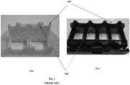
- FIG. 1 One outstanding drawback of the existing connector adapter is illustrated in figure 1 of the accompanying drawings.
- a single flat is provided in the adapter at the protrusion for receiving the connection plug.
- the single flat constitute both the snap and bearing area. Due to this the connector anchored in the adapter will be having excessive play/loose causing inconvenience to the user.
- the present invention focuses of robust fixation of connector while ensuring annular clearance between the connector plug and centre plate opening. Accordingly the present invention provides an adapter for releasably engaging a connector plug, said adapter comprising:
- said connector bearing surfaces are disposed in both side of said cantilever snap to anchor said connector plug into said adapter.
- said extended cantilever portion has a wedged top surface which upon applying positive pressure resiliently bends to increase the size of the opening to assemble said connector plug.
- said stopper ribs have a planer surface attached to the ribs to locate and support the connector plug.
- said stopper ribs are positioned about the middle of the top wall.
- said connector bearing surface supports said connector plug and restricts the movement of said connector plug.
- said pair of guiding protrusions extends perpendicular to said side walls defining a passage in both sides of said stopper ribs to guide the ribs of said connector plug.
- said housing comprises a pair of fixing protrusion at the top and bottom portion of said adapter to removable fix with a fixing frame.
- said connector plug is a RJ45 type connector plug.
- said adapter providing a housing for said connector plug.
- an adapter (100) for releasably engaging a connector plug (200) is disclosed herein.
- the adapter in general is engaged to a fixing frame (30) on a wall box, or may be installed in power racks.
- Said adapter (100) is used to anchor the connector plug, here a Registered Jack (RJ)-type connector plug (200), more specifically a RJ45 connector plug.
- RJ Registered Jack
- said adapter provides a housing for said connector plug (200).
- the adapter (100) as illustrated in figures 2-5 comprises a first surface a second surface and two opposing side walls (108).
- the first surface can be considered to be a top wall (105) and the second surface can be considered as bottom wall (106).
- the side surfaces, as seen in the figure have matching planner profile with the connector plug (200) to be housed in said adapter (100).
- the top wall (105) and the bottom wall (106) are provided with fixing structures to anchor said connector plug (200).
- the fixing structures of the top wall (105) and the bottom wall (106) functions in conjunction with each other providing a robust fixation to the connector plug (200).
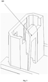
- top wall (105) of the adapter (100) is depicted in figure 4 of the accompanying drawings.
- the top wall (105) is provided with feature of stopper ribs and the feature of guiding protrusions (107).
- the stopper rib(s) (104) could be a single extension from the top wall (105). Alternatively, two extensions can be provided that protrude from the top wall (105) ( Fig. 5 ).
- the extended ends of the ribs forms a planner surface which enables the stopper feature.
- the planner surface is of matching profile with the clearance available at the top surface of RJ45 connector plug (200) as illustrated in figure 5 of the accompanying drawings.
- the fixing structure of the bottom wall (106) of the adapter (100) is shown in figure 3 of the accompanying drawings.
- the extension of the cantilever is parallel to the plane surface of the stopper ribs (104) of said top wall (105).
- the fixed end is attached to said bottom wall (106) such that upon action of any positive force the extended end bends resiliently.
- the extended end (103) has a slope for the ease of anchoring the connector plug (200).
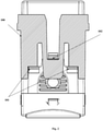
- FIG. 2 , 8 and 9 the feature of connector bearing surface (101) and cantilever snap (102) feature are depicted. These two feature diligently solves the problems in the existing adapters (100') for connector plug (200) shown in figure 1 (a&b).
- the single flat constitute both the snap (105') and bearing area (106').
- the invented adapter (100) the single flat wall for anchoring the connector plug (200) has been removed and instead an adapter bearing surface (101) and cantilever snap (102) feature is introduced.
- the anchoring of the connector plug within the adapter (100) is illustrated in figure 8 with the arrow signs directing the direction of insertion of the connector plug (200).
- the extended cantilever portion (103) of the bottom wall (106) the stopper ribs (104) feature of the top wall (105) receives the connector plug (200).
- the connector bearing surface (101) as seen in figure 8 makes sure that the connector rests on the surface and bears the load of the connector.
- Figures 1 , 2 , 9 and 10 depicts the connector plug (200) engaged with the invented adapter (100).
- the RJ45 type of connector plugs are provided with bearing surface (211).
- the connector bearing surface (101) is of matching profile to that of the bearing surface (212) of the of connector plug (200).
- the bearing surface of the adapter (100) controls the movement of the RJ45 adapter plug along the +Z axis.
- the adapter (100) is provided with a cantilever snap (102) functioning congruently with said connector bearing surface (101) as depicted in fugue 1.
- the top wall (105), the bottom wall (106) and the side walls (108) defines a rectangular opening for the insertion of said connector plug (200).
- a pair of guiding protrusions (107) are provided at the top wall (105) of the adapter (100).
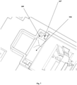
- Figure 7 of the accompanying drawings depicts how the features of stopper ribs (104), the guiding projections (107) of the top wall (105) works in conjunction with the guiding protrusions (107) of the adapter (100) to anchor said connector plug (200).
- the top and/or bottom housing portion of said adapter (100) is provided with a fixing protrusion (109) for attaching with wall box. Fist the connector plug (200) is engaged with the adapter ( Fig 9 ) and then the adapter assembly is assembled with a fixing frame (30) of a wall-box (not show explicitly) as seen in the figure 11 . As seen in the figure 5 , for anchoring the connector plug with the adapter (100), the guiding protrusions (107) of the RJ45 connector plug (200) are aligned with respect to the guiding protrusions (107) of said adapter (100).
- the predetermined gap kept between the guiding protrusions (107) and the stopper ribs (104) matched with the guiding protrusions (29) of the RJ45 connector plug (200).
- the guiding protrusions (107) provided at the top wall of the adapter receives the RJ45 connector plug (200) and a robust fixation is achieved.
- the invented connector adapter (100) have a modular solution for engaging more than one connector plug in parallel succession.
- this modular design depends on the type of wall box or racks used for engaging the adapter (100) onto them.
- Figure 6 in specific depicts a constitution of the adapter (100) for housing two connector plugs (200).
- the top walls (105) and the bottom walls (106) of the adapter (100) are constructed in a continuous manner.
- a shared side wall (108) is provided for segregating two slots for anchoring two connector plug (2) as illustrated in the figure.
- the shared side wall (108) of the adapter (100) is provided with plurality of lips for receiving the connector plugs (200).
- the adapter bearing surface the snap feature is also depicted in the figure which is provided at both section of the adapter providing robust support to the connector plugs (200).
Landscapes
- Details Of Connecting Devices For Male And Female Coupling (AREA)
- Connector Housings Or Holding Contact Members (AREA)
Abstract
Description
- The present invention relates to adapter for releasibly engaging electrical connector plugs. Specifically, this invention relates to a connector adapter for Registered Jack (RJ) type connector plugs, and more specifically for a RJ45 type connector plug.
- Electrical connectors that are commonly used in telecommunication systems provide an interface between successive runs of cables and/or between cables and electronic devices of the system. An accessory may communicate with a portable electronic device using a connector system. This connector system may include a plug connector that is associated with the accessory and a receptacle connector that is associated with the portable electronic device. RJ modular connectors have been widely used in telecommunication systems ever since they were first created and adopted by the industry. An RJ45 modular connector, which includes a total of eight terminals has been widely used in the network systems.
- A user may connect the plug connector of the accessory to the receptacle connector of the portable electronic device thereby forming physical and electrical connections between the contacts of each of the connectors. The host device and the accessory may then exchange data and/or send/receive power using the connectors. Often, the adapter defines the interface between an outside box connector and an inside box connector.
- The adapters for anchoring the RJ type connector plugs known in the art fail to provide the adequate play to the connectors. One outstanding drawback of the existing connector adapter is illustrated in
figure 1 of the accompanying drawings. As seen in the figure, a single flat is provided in the adapter at the protrusion for receiving the connection plug. The single flat constitute both the snap and bearing area. Due to this the connector anchored in the adapter will be having excessive play/loose causing inconvenience to the user. - Further, some of the problems in existing adapter include:
- No dedicated support features for the connector plug;
- Connector are pushed inside the wall-box while inserting plug;
- Loose/play in connector leads to the tiling of connector and resulting to shutter stuck-up.
- With a view therefore to the problem associated with the conventional anchoring/fixing techniques of connector adapter system the inventors felt to need to develop a novel connector adapter for releasably attach a connector plug, particularly for a RJ45 type of connector plug anchored in said connector adapter and providing a connector bearing surface in conjunction with cantilever snap to anchor said connector plug into said adapter which restricts any loose movement of the connector plug. With the top wall of the adapter provided with stopper ribs to locate the insertion of said connector plug and bottom wall is provided with extended cantilever which at insertion of connector plug resiliently bend and receive said connector plug. Thus the invented adapter provides a safe and convenient modular solution to the problem addressed.
- Present invention focuses of robust fixation of connector while ensuring annular clearance between the connector plug and centre plate opening. Accordingly the present invention provides an adapter for releasably engaging a connector plug, said adapter comprising:
- connector bearing surfaces, a cantilever snap, a first surface defining a top wall, a second surface defining a bottom wall and two opposing side walls, said walls defining an opening for said connector plug,
- According to a most preferred embodiment of the invention said top wall is provided with
- stopper ribs extending from said top wall to locate the insertion of said connector plug; and
- pair of guiding protrusions to receive the connector plug in a guided manner;
- According to the most preferred embodiment said connector bearing surfaces are disposed in both side of said cantilever snap to anchor said connector plug into said adapter.
- According to one embodiment of the invention, said extended cantilever portion has a wedged top surface which upon applying positive pressure resiliently bends to increase the size of the opening to assemble said connector plug.
- According to one object of the invention, said stopper ribs have a planer surface attached to the ribs to locate and support the connector plug.
- According to one embodiment of the invented adapter said stopper ribs are positioned about the middle of the top wall.
- According to another object of the invention, said connector bearing surface supports said connector plug and restricts the movement of said connector plug.
- According to one embodiment of the invented adapter for releasably engaging a connector plug said pair of guiding protrusions extends perpendicular to said side walls defining a passage in both sides of said stopper ribs to guide the ribs of said connector plug.
- According to one embodiment of the invention said housing comprises a pair of fixing protrusion at the top and bottom portion of said adapter to removable fix with a fixing frame.
- According to one embodiment of the invention, said connector plug is a RJ45 type connector plug.
- According to yet another object of the invention said adapter providing a housing for said connector plug.
- For better understanding, an illustrative embodiment of the invention will now be described with reference to the accompanying drawings. It will however be appreciated that the embodiment exemplified in the drawings are merely illustrative and not limitative to the scope of the invention, because it is quite possible, indeed often desirable, to introduce a number of variations in the embodiment that have been shown in the drawings. In the accompanying drawings:
-
Figure 1 depict the existing adapter assembly showing the drawbacks of the embodiments; -
Figure 2 depicts the connector bearing surface and the snapping feature of the invented connector adapter according to one embodiment of the invention; -
Figure 3 depicts the extended cantilever portion at the bottom wall of the adapter according to one embodiment of the invention; -
Figure 4 depicts the feature of stopper ribs at the top wall of the adapter according to one embodiment of the invention; -
Figure 5 depicts the perspective view of the invented adapter and the connector plug aligned with each other according to one embodiment of the invention; -
Figure 6 depicts a modular solution for attaching more than one connector plug with the invented adapter according to one embodiment of the invention; -
Figure 7 is a view inside the adapter showing the interconnection of the features of the adapter. -
Figure 8 illustrates the insertion of the connector plug inside the adapter; -
Figure 9 depicts a first side the assembly of the connector plug and the adapter when the connector plug is anchored according to one embodiment of the invention; -
Figure 10 depicts a second side the assembly of the connector plug and the adapter when the connector plug is anchored according to one embodiment of the invention; -
Figure 11 depicts the assembly of the invented adapter on a fixing frame according to one embodiment of the invention. - With reference to
figures 2-11 of the accompanying drawings, an adapter (100) for releasably engaging a connector plug (200) is disclosed herein. The adapter, in general is engaged to a fixing frame (30) on a wall box, or may be installed in power racks. Said adapter (100) is used to anchor the connector plug, here a Registered Jack (RJ)-type connector plug (200), more specifically a RJ45 connector plug. As discussed, said adapter provides a housing for said connector plug (200). - The adapter (100) as illustrated in
figures 2-5 comprises a first surface a second surface and two opposing side walls (108). In a particular arrangement of the adapter (100) as depicted infigure 5 , the first surface can be considered to be a top wall (105) and the second surface can be considered as bottom wall (106). The side surfaces, as seen in the figure have matching planner profile with the connector plug (200) to be housed in said adapter (100). The top wall (105) and the bottom wall (106) are provided with fixing structures to anchor said connector plug (200). The fixing structures of the top wall (105) and the bottom wall (106) functions in conjunction with each other providing a robust fixation to the connector plug (200). - The fixing structures of top wall (105) of the adapter (100) is depicted in
figure 4 of the accompanying drawings. The top wall (105) is provided with feature of stopper ribs and the feature of guiding protrusions (107). The stopper rib(s) (104) could be a single extension from the top wall (105). Alternatively, two extensions can be provided that protrude from the top wall (105) (Fig. 5 ). The extended ends of the ribs forms a planner surface which enables the stopper feature. The planner surface is of matching profile with the clearance available at the top surface of RJ45 connector plug (200) as illustrated infigure 5 of the accompanying drawings. - The fixing structure of the bottom wall (106) of the adapter (100) is shown in
figure 3 of the accompanying drawings. The bottom wall (106) with feature of extended cantilever portion (103). The extension of the cantilever is parallel to the plane surface of the stopper ribs (104) of said top wall (105). The fixed end is attached to said bottom wall (106) such that upon action of any positive force the extended end bends resiliently. As seenfigures 3 and5 , the extended end (103) has a slope for the ease of anchoring the connector plug (200). - In the
figures 2 ,8 and9 the feature of connector bearing surface (101) and cantilever snap (102) feature are depicted. These two feature diligently solves the problems in the existing adapters (100') for connector plug (200) shown infigure 1 (a&b). The single flat constitute both the snap (105') and bearing area (106'). In the invented adapter (100), the single flat wall for anchoring the connector plug (200) has been removed and instead an adapter bearing surface (101) and cantilever snap (102) feature is introduced. - The anchoring of the connector plug within the adapter (100) is illustrated in
figure 8 with the arrow signs directing the direction of insertion of the connector plug (200). Upon applying positive pressure with the connector plug, the extended cantilever portion (103) of the bottom wall (106) the stopper ribs (104) feature of the top wall (105) receives the connector plug (200). The connector bearing surface (101) as seen infigure 8 makes sure that the connector rests on the surface and bears the load of the connector. -
Figures 1 ,2 ,9 and10 depicts the connector plug (200) engaged with the invented adapter (100). In general the RJ45 type of connector plugs are provided with bearing surface (211). As seen infigure 10 of the accompanying drawings the connector bearing surface (101) is of matching profile to that of the bearing surface (212) of the of connector plug (200). While attaching wire and the conduits with the connector, the bearing surface of the adapter (100) controls the movement of the RJ45 adapter plug along the +Z axis. The adapter (100) is provided with a cantilever snap (102) functioning congruently with said connector bearing surface (101) as depicted infugue 1. These two features prevents any pushing force or twists applied on the connector at the time of assembly as illustrated infigure 9 of the accompanying drawings. - With reference to
figure 5 of the corresponding drawings, the top wall (105), the bottom wall (106) and the side walls (108) defines a rectangular opening for the insertion of said connector plug (200). As seen in the figure, a pair of guiding protrusions (107) are provided at the top wall (105) of the adapter (100). The guiding protrusions (107), in this particular embodiment of the invention of provide at both side of the stopper ribs (104) feature. Predetermined gaps are introduced between the plane surface of the stopper ribs (104) and the guiding protrusions. The gap kept at both sides of the stopper ribs are identical.Figure 7 of the accompanying drawings depicts how the features of stopper ribs (104), the guiding projections (107) of the top wall (105) works in conjunction with the guiding protrusions (107) of the adapter (100) to anchor said connector plug (200). - In the orientation of said connector plug (200), the top and/or bottom housing portion of said adapter (100) is provided with a fixing protrusion (109) for attaching with wall box. Fist the connector plug (200) is engaged with the adapter (
Fig 9 ) and then the adapter assembly is assembled with a fixing frame (30) of a wall-box (not show explicitly) as seen in thefigure 11 . As seen in thefigure 5 , for anchoring the connector plug with the adapter (100), the guiding protrusions (107) of the RJ45 connector plug (200) are aligned with respect to the guiding protrusions (107) of said adapter (100). The predetermined gap kept between the guiding protrusions (107) and the stopper ribs (104) matched with the guiding protrusions (29) of the RJ45 connector plug (200). Thus the guiding protrusions (107) provided at the top wall of the adapter receives the RJ45 connector plug (200) and a robust fixation is achieved. - According to the embodiment shown in the
figure 6 of the accompanying drawings the invented connector adapter (100) have a modular solution for engaging more than one connector plug in parallel succession. In general this modular design depends on the type of wall box or racks used for engaging the adapter (100) onto them. The length of the adapter by the slot provided at the rack or wall box.Figure 6 in specific depicts a constitution of the adapter (100) for housing two connector plugs (200). The top walls (105) and the bottom walls (106) of the adapter (100) are constructed in a continuous manner. A shared side wall (108) is provided for segregating two slots for anchoring two connector plug (2) as illustrated in the figure. The shared side wall (108) of the adapter (100) is provided with plurality of lips for receiving the connector plugs (200). The adapter bearing surface the snap feature is also depicted in the figure which is provided at both section of the adapter providing robust support to the connector plugs (200).
Claims (9)
- An adapter (100) for releasably engaging with a connector plug (200), said adapter (100) comprising:connector bearing surfaces (101), a cantilever snap (102), a first surface defining a top wall (105), a second surface defining a bottom wall (106) and two opposing side walls (108), said walls (105,106,108) defining an opening for engaging said connector plug (200), wherein said top wall (105) is provided with- stopper ribs (104) extending from said top wall (105) to locate the insertion of said connector plug (200); and- pair of guiding protrusions (107) to receive the connector plug (200) in a guided manner;and said bottom wall (106) is provided with extended cantilever portion (103) which upon insertion of said connector plug (200) is configured to resiliently bend and receive said connector plug;and wherein said connector bearing surfaces (101) are disposed in both side of said cantilever snap (102) to anchor said connector plug (200) into said adapter (100).
- The adapter (100) for releasably engaging a connector plug (200) as claimed in claim 1, wherein said extended cantilever portion (103) has a wedged top surface which upon applying positive pressure resiliently bends to increase the size of the opening to assemble said connector plug (200).
- The adapter (100) for releasably engaging a connector plug (200) as claimed in claim 1, wherein said stopper ribs (104) have a planer surface attached to the ribs to locate and support the connector plug (200).
- The adapter (100) for releasably engaging a connector plug (200) as claimed in claim 3, wherein said stopper ribs (104) are positioned about the middle of the top wall (105).
- The adapter (100) for releasably engaging a connector plug (200) as claimed in claim 1, wherein said connector bearing surface (101) supports said connector plug (200) and restricts the movement of said connector plug (200).
- The adapter (100) for releasably engaging a connector plug (200) as claimed in claim 1, wherein said pair of guiding protrusions (107) extends perpendicular to said side walls (108) defining a passage in both sides of said stopper ribs (104) to guide the ribs of said connector plug (200).
- The adapter (100) for releasably engaging a connector plug (200) as claimed in claim 1, wherein said connector plug is a RJ45 type connector plug (200).
- The adapter (100) for releasably engaging a connector plug (200) as claimed in claim 1, wherein said adapter (100) comprises a pair of fixing protrusion (109) at the top and/or bottom portion of said adapter (100) to removable fix with a fixing frame (30).
- The adapter (100) for releasably engaging a connector plug (200) as claimed in claim 1, wherein said adapter provides a housing for said connector plug (200).
Applications Claiming Priority (1)
| Application Number | Priority Date | Filing Date | Title |
|---|---|---|---|
| IN202031033722 | 2020-08-06 |
Publications (3)
| Publication Number | Publication Date |
|---|---|
| EP3952034A1 true EP3952034A1 (en) | 2022-02-09 |
| EP3952034C0 EP3952034C0 (en) | 2024-08-21 |
| EP3952034B1 EP3952034B1 (en) | 2024-08-21 |
Family
ID=76920564
Family Applications (1)
| Application Number | Title | Priority Date | Filing Date |
|---|---|---|---|
| EP21185301.5A Active EP3952034B1 (en) | 2020-08-06 | 2021-07-13 | Adapter for rj 45 connector |
Country Status (1)
| Country | Link |
|---|---|
| EP (1) | EP3952034B1 (en) |
Cited By (2)
| Publication number | Priority date | Publication date | Assignee | Title |
|---|---|---|---|---|
| WO2025099752A1 (en) * | 2023-11-07 | 2025-05-15 | Enermore Technologies Llp | Casing for electrical connectors |
| WO2025119422A1 (en) * | 2023-12-05 | 2025-06-12 | Harting Electric Stiftung & Co. Kg | Connector module for a modular industrial connector |
Citations (4)
| Publication number | Priority date | Publication date | Assignee | Title |
|---|---|---|---|---|
| US5096439A (en) * | 1991-08-28 | 1992-03-17 | At&T Bell Laboratories | Wall plate having jack-release slots |
| EP0887893A2 (en) * | 1997-05-30 | 1998-12-30 | Lucent Technologies Inc. | Multi-position jack frame |
| US6394844B1 (en) * | 2000-02-21 | 2002-05-28 | Tyco Electronics Amp Espanola, S.A. | Electrical connector for high speed signal transmission |
| US9577396B2 (en) * | 2015-04-24 | 2017-02-21 | Belden Canada Inc. | Keystone jack adaptor |
-
2021
- 2021-07-13 EP EP21185301.5A patent/EP3952034B1/en active Active
Patent Citations (4)
| Publication number | Priority date | Publication date | Assignee | Title |
|---|---|---|---|---|
| US5096439A (en) * | 1991-08-28 | 1992-03-17 | At&T Bell Laboratories | Wall plate having jack-release slots |
| EP0887893A2 (en) * | 1997-05-30 | 1998-12-30 | Lucent Technologies Inc. | Multi-position jack frame |
| US6394844B1 (en) * | 2000-02-21 | 2002-05-28 | Tyco Electronics Amp Espanola, S.A. | Electrical connector for high speed signal transmission |
| US9577396B2 (en) * | 2015-04-24 | 2017-02-21 | Belden Canada Inc. | Keystone jack adaptor |
Cited By (2)
| Publication number | Priority date | Publication date | Assignee | Title |
|---|---|---|---|---|
| WO2025099752A1 (en) * | 2023-11-07 | 2025-05-15 | Enermore Technologies Llp | Casing for electrical connectors |
| WO2025119422A1 (en) * | 2023-12-05 | 2025-06-12 | Harting Electric Stiftung & Co. Kg | Connector module for a modular industrial connector |
Also Published As
| Publication number | Publication date |
|---|---|
| EP3952034C0 (en) | 2024-08-21 |
| EP3952034B1 (en) | 2024-08-21 |
Similar Documents
| Publication | Publication Date | Title |
|---|---|---|
| US4103985A (en) | Connector adapter constructions with improved connection and connector mounting arrangement | |
| US5096439A (en) | Wall plate having jack-release slots | |
| US4220391A (en) | Connector adapter constructions with improved connector and connector mounting arrangement | |
| US6307997B1 (en) | Termination block for optical fiber cables | |
| CN103257407B (en) | Connector and connector assembly | |
| US12355196B2 (en) | Latch for telecommunications connector | |
| KR100238930B1 (en) | Pluggable modular splicing connectors and bridging adapters | |
| RU2406194C1 (en) | Adapter and plug-and-socket connection system | |
| US5562493A (en) | Network interface assembly and mounting frame | |
| US8439708B2 (en) | Electrical connector with cantilevered arm integrally formed on metal shell | |
| US5041018A (en) | Electrical connector receptacle | |
| CN111328450B (en) | Telecommunications board with patch device mounting features | |
| CN114730058A (en) | Optical module, communication equipment and PoE equipment | |
| CN111403933B (en) | Wire end connector | |
| EP3952034B1 (en) | Adapter for rj 45 connector | |
| JPH04233022A (en) | Female type electric connector having shield | |
| CN214954260U (en) | Optical fiber distribution box | |
| US5228869A (en) | Panel yoke and snap locking mounting scheme for securing wire connectors | |
| EP3739694A1 (en) | Connector housing, mating connector housing and system | |
| US6019641A (en) | Electric connector | |
| CN111628328B (en) | Electrical connector | |
| CN101458381B (en) | Optical signal distribution assembly with optical connector holder | |
| US6315589B1 (en) | Connector for combined DC/data bus | |
| US20230236376A1 (en) | Network interface device bracket | |
| CN113196578B (en) | Plug-in connector components for contacting in several spatial directions |
Legal Events
| Date | Code | Title | Description |
|---|---|---|---|
| PUAI | Public reference made under article 153(3) epc to a published international application that has entered the european phase |
Free format text: ORIGINAL CODE: 0009012 |
|
| STAA | Information on the status of an ep patent application or granted ep patent |
Free format text: STATUS: REQUEST FOR EXAMINATION WAS MADE |
|
| 17P | Request for examination filed |
Effective date: 20210713 |
|
| AK | Designated contracting states |
Kind code of ref document: A1 Designated state(s): AL AT BE BG CH CY CZ DE DK EE ES FI FR GB GR HR HU IE IS IT LI LT LU LV MC MK MT NL NO PL PT RO RS SE SI SK SM TR |
|
| GRAP | Despatch of communication of intention to grant a patent |
Free format text: ORIGINAL CODE: EPIDOSNIGR1 |
|
| STAA | Information on the status of an ep patent application or granted ep patent |
Free format text: STATUS: GRANT OF PATENT IS INTENDED |
|
| RIC1 | Information provided on ipc code assigned before grant |
Ipc: H01R 24/64 20110101ALN20240214BHEP Ipc: H01R 13/516 20060101ALI20240214BHEP Ipc: H01R 31/06 20060101AFI20240214BHEP |
|
| INTG | Intention to grant announced |
Effective date: 20240229 |
|
| RIC1 | Information provided on ipc code assigned before grant |
Ipc: H01R 24/64 20110101ALN20240219BHEP Ipc: H01R 13/516 20060101ALI20240219BHEP Ipc: H01R 31/06 20060101AFI20240219BHEP |
|
| GRAS | Grant fee paid |
Free format text: ORIGINAL CODE: EPIDOSNIGR3 |
|
| GRAA | (expected) grant |
Free format text: ORIGINAL CODE: 0009210 |
|
| STAA | Information on the status of an ep patent application or granted ep patent |
Free format text: STATUS: THE PATENT HAS BEEN GRANTED |
|
| AK | Designated contracting states |
Kind code of ref document: B1 Designated state(s): AL AT BE BG CH CY CZ DE DK EE ES FI FR GB GR HR HU IE IS IT LI LT LU LV MC MK MT NL NO PL PT RO RS SE SI SK SM TR |
|
| REG | Reference to a national code |
Ref country code: GB Ref legal event code: FG4D |
|
| REG | Reference to a national code |
Ref country code: CH Ref legal event code: EP |
|
| REG | Reference to a national code |
Ref country code: IE Ref legal event code: FG4D |
|
| REG | Reference to a national code |
Ref country code: DE Ref legal event code: R096 Ref document number: 602021017423 Country of ref document: DE |
|
| U01 | Request for unitary effect filed |
Effective date: 20240910 |
|
| U07 | Unitary effect registered |
Designated state(s): AT BE BG DE DK EE FI FR IT LT LU LV MT NL PT RO SE SI Effective date: 20240926 |
|
| PG25 | Lapsed in a contracting state [announced via postgrant information from national office to epo] |
Ref country code: NO Free format text: LAPSE BECAUSE OF FAILURE TO SUBMIT A TRANSLATION OF THE DESCRIPTION OR TO PAY THE FEE WITHIN THE PRESCRIBED TIME-LIMIT Effective date: 20241121 |
|
| PG25 | Lapsed in a contracting state [announced via postgrant information from national office to epo] |
Ref country code: PL Free format text: LAPSE BECAUSE OF FAILURE TO SUBMIT A TRANSLATION OF THE DESCRIPTION OR TO PAY THE FEE WITHIN THE PRESCRIBED TIME-LIMIT Effective date: 20240821 Ref country code: GR Free format text: LAPSE BECAUSE OF FAILURE TO SUBMIT A TRANSLATION OF THE DESCRIPTION OR TO PAY THE FEE WITHIN THE PRESCRIBED TIME-LIMIT Effective date: 20241122 |
|
| PG25 | Lapsed in a contracting state [announced via postgrant information from national office to epo] |
Ref country code: IS Free format text: LAPSE BECAUSE OF FAILURE TO SUBMIT A TRANSLATION OF THE DESCRIPTION OR TO PAY THE FEE WITHIN THE PRESCRIBED TIME-LIMIT Effective date: 20241221 |
|
| PG25 | Lapsed in a contracting state [announced via postgrant information from national office to epo] |
Ref country code: HR Free format text: LAPSE BECAUSE OF FAILURE TO SUBMIT A TRANSLATION OF THE DESCRIPTION OR TO PAY THE FEE WITHIN THE PRESCRIBED TIME-LIMIT Effective date: 20240821 |
|
| PG25 | Lapsed in a contracting state [announced via postgrant information from national office to epo] |
Ref country code: RS Free format text: LAPSE BECAUSE OF FAILURE TO SUBMIT A TRANSLATION OF THE DESCRIPTION OR TO PAY THE FEE WITHIN THE PRESCRIBED TIME-LIMIT Effective date: 20241121 Ref country code: ES Free format text: LAPSE BECAUSE OF FAILURE TO SUBMIT A TRANSLATION OF THE DESCRIPTION OR TO PAY THE FEE WITHIN THE PRESCRIBED TIME-LIMIT Effective date: 20240821 |
|
| PG25 | Lapsed in a contracting state [announced via postgrant information from national office to epo] |
Ref country code: RS Free format text: LAPSE BECAUSE OF FAILURE TO SUBMIT A TRANSLATION OF THE DESCRIPTION OR TO PAY THE FEE WITHIN THE PRESCRIBED TIME-LIMIT Effective date: 20241121 Ref country code: PL Free format text: LAPSE BECAUSE OF FAILURE TO SUBMIT A TRANSLATION OF THE DESCRIPTION OR TO PAY THE FEE WITHIN THE PRESCRIBED TIME-LIMIT Effective date: 20240821 Ref country code: NO Free format text: LAPSE BECAUSE OF FAILURE TO SUBMIT A TRANSLATION OF THE DESCRIPTION OR TO PAY THE FEE WITHIN THE PRESCRIBED TIME-LIMIT Effective date: 20241121 Ref country code: IS Free format text: LAPSE BECAUSE OF FAILURE TO SUBMIT A TRANSLATION OF THE DESCRIPTION OR TO PAY THE FEE WITHIN THE PRESCRIBED TIME-LIMIT Effective date: 20241221 Ref country code: HR Free format text: LAPSE BECAUSE OF FAILURE TO SUBMIT A TRANSLATION OF THE DESCRIPTION OR TO PAY THE FEE WITHIN THE PRESCRIBED TIME-LIMIT Effective date: 20240821 Ref country code: GR Free format text: LAPSE BECAUSE OF FAILURE TO SUBMIT A TRANSLATION OF THE DESCRIPTION OR TO PAY THE FEE WITHIN THE PRESCRIBED TIME-LIMIT Effective date: 20241122 Ref country code: ES Free format text: LAPSE BECAUSE OF FAILURE TO SUBMIT A TRANSLATION OF THE DESCRIPTION OR TO PAY THE FEE WITHIN THE PRESCRIBED TIME-LIMIT Effective date: 20240821 |
|
| PG25 | Lapsed in a contracting state [announced via postgrant information from national office to epo] |
Ref country code: SM Free format text: LAPSE BECAUSE OF FAILURE TO SUBMIT A TRANSLATION OF THE DESCRIPTION OR TO PAY THE FEE WITHIN THE PRESCRIBED TIME-LIMIT Effective date: 20240821 |
|
| PG25 | Lapsed in a contracting state [announced via postgrant information from national office to epo] |
Ref country code: CZ Free format text: LAPSE BECAUSE OF FAILURE TO SUBMIT A TRANSLATION OF THE DESCRIPTION OR TO PAY THE FEE WITHIN THE PRESCRIBED TIME-LIMIT Effective date: 20240821 |
|
| PG25 | Lapsed in a contracting state [announced via postgrant information from national office to epo] |
Ref country code: SK Free format text: LAPSE BECAUSE OF FAILURE TO SUBMIT A TRANSLATION OF THE DESCRIPTION OR TO PAY THE FEE WITHIN THE PRESCRIBED TIME-LIMIT Effective date: 20240821 |
|
| PLBE | No opposition filed within time limit |
Free format text: ORIGINAL CODE: 0009261 |
|
| STAA | Information on the status of an ep patent application or granted ep patent |
Free format text: STATUS: NO OPPOSITION FILED WITHIN TIME LIMIT |
|
| 26N | No opposition filed |
Effective date: 20250522 |
|
| U20 | Renewal fee for the european patent with unitary effect paid |
Year of fee payment: 5 Effective date: 20250711 |
|
| REG | Reference to a national code |
Ref country code: CH Ref legal event code: H13 Free format text: ST27 STATUS EVENT CODE: U-0-0-H10-H13 (AS PROVIDED BY THE NATIONAL OFFICE) Effective date: 20260224 |
|
| GBPC | Gb: european patent ceased through non-payment of renewal fee |
Effective date: 20250713 |
|
| PG25 | Lapsed in a contracting state [announced via postgrant information from national office to epo] |
Ref country code: GB Free format text: LAPSE BECAUSE OF NON-PAYMENT OF DUE FEES Effective date: 20250713 |
|
| PG25 | Lapsed in a contracting state [announced via postgrant information from national office to epo] |
Ref country code: CH Free format text: LAPSE BECAUSE OF NON-PAYMENT OF DUE FEES Effective date: 20250731 |