EP3951921A1 - Fabrication method of positive electrode for secondary battery and secondary battery including the positive electrode - Google Patents
Fabrication method of positive electrode for secondary battery and secondary battery including the positive electrode Download PDFInfo
- Publication number
- EP3951921A1 EP3951921A1 EP21189192.4A EP21189192A EP3951921A1 EP 3951921 A1 EP3951921 A1 EP 3951921A1 EP 21189192 A EP21189192 A EP 21189192A EP 3951921 A1 EP3951921 A1 EP 3951921A1
- Authority
- EP
- European Patent Office
- Prior art keywords
- positive electrode
- slurry composition
- active material
- secondary battery
- slurry
- Prior art date
- Legal status (The legal status is an assumption and is not a legal conclusion. Google has not performed a legal analysis and makes no representation as to the accuracy of the status listed.)
- Pending
Links
Images

Classifications
-
- H—ELECTRICITY
- H01—ELECTRIC ELEMENTS
- H01M—PROCESSES OR MEANS, e.g. BATTERIES, FOR THE DIRECT CONVERSION OF CHEMICAL ENERGY INTO ELECTRICAL ENERGY
- H01M4/00—Electrodes
- H01M4/02—Electrodes composed of, or comprising, active material
- H01M4/13—Electrodes for accumulators with non-aqueous electrolyte, e.g. for lithium-accumulators; Processes of manufacture thereof
- H01M4/139—Processes of manufacture
-
- H—ELECTRICITY
- H01—ELECTRIC ELEMENTS
- H01M—PROCESSES OR MEANS, e.g. BATTERIES, FOR THE DIRECT CONVERSION OF CHEMICAL ENERGY INTO ELECTRICAL ENERGY
- H01M10/00—Secondary cells; Manufacture thereof
- H01M10/04—Construction or manufacture in general
-
- H—ELECTRICITY
- H01—ELECTRIC ELEMENTS
- H01M—PROCESSES OR MEANS, e.g. BATTERIES, FOR THE DIRECT CONVERSION OF CHEMICAL ENERGY INTO ELECTRICAL ENERGY
- H01M10/00—Secondary cells; Manufacture thereof
- H01M10/05—Accumulators with non-aqueous electrolyte
-
- H—ELECTRICITY
- H01—ELECTRIC ELEMENTS
- H01M—PROCESSES OR MEANS, e.g. BATTERIES, FOR THE DIRECT CONVERSION OF CHEMICAL ENERGY INTO ELECTRICAL ENERGY
- H01M4/00—Electrodes
- H01M4/02—Electrodes composed of, or comprising, active material
- H01M4/04—Processes of manufacture in general
- H01M4/0402—Methods of deposition of the material
- H01M4/0404—Methods of deposition of the material by coating on electrode collectors
-
- H—ELECTRICITY
- H01—ELECTRIC ELEMENTS
- H01M—PROCESSES OR MEANS, e.g. BATTERIES, FOR THE DIRECT CONVERSION OF CHEMICAL ENERGY INTO ELECTRICAL ENERGY
- H01M4/00—Electrodes
- H01M4/02—Electrodes composed of, or comprising, active material
- H01M4/04—Processes of manufacture in general
- H01M4/0471—Processes of manufacture in general involving thermal treatment, e.g. firing, sintering, backing particulate active material, thermal decomposition, pyrolysis
-
- H—ELECTRICITY
- H01—ELECTRIC ELEMENTS
- H01M—PROCESSES OR MEANS, e.g. BATTERIES, FOR THE DIRECT CONVERSION OF CHEMICAL ENERGY INTO ELECTRICAL ENERGY
- H01M4/00—Electrodes
- H01M4/02—Electrodes composed of, or comprising, active material
- H01M4/13—Electrodes for accumulators with non-aqueous electrolyte, e.g. for lithium-accumulators; Processes of manufacture thereof
-
- H—ELECTRICITY
- H01—ELECTRIC ELEMENTS
- H01M—PROCESSES OR MEANS, e.g. BATTERIES, FOR THE DIRECT CONVERSION OF CHEMICAL ENERGY INTO ELECTRICAL ENERGY
- H01M4/00—Electrodes
- H01M4/02—Electrodes composed of, or comprising, active material
- H01M4/13—Electrodes for accumulators with non-aqueous electrolyte, e.g. for lithium-accumulators; Processes of manufacture thereof
- H01M4/131—Electrodes based on mixed oxides or hydroxides, or on mixtures of oxides or hydroxides, e.g. LiCoOx
-
- H—ELECTRICITY
- H01—ELECTRIC ELEMENTS
- H01M—PROCESSES OR MEANS, e.g. BATTERIES, FOR THE DIRECT CONVERSION OF CHEMICAL ENERGY INTO ELECTRICAL ENERGY
- H01M4/00—Electrodes
- H01M4/02—Electrodes composed of, or comprising, active material
- H01M4/13—Electrodes for accumulators with non-aqueous electrolyte, e.g. for lithium-accumulators; Processes of manufacture thereof
- H01M4/139—Processes of manufacture
- H01M4/1391—Processes of manufacture of electrodes based on mixed oxides or hydroxides, or on mixtures of oxides or hydroxides, e.g. LiCoOx
-
- H—ELECTRICITY
- H01—ELECTRIC ELEMENTS
- H01M—PROCESSES OR MEANS, e.g. BATTERIES, FOR THE DIRECT CONVERSION OF CHEMICAL ENERGY INTO ELECTRICAL ENERGY
- H01M4/00—Electrodes
- H01M4/02—Electrodes composed of, or comprising, active material
- H01M4/36—Selection of substances as active materials, active masses, active liquids
- H01M4/48—Selection of substances as active materials, active masses, active liquids of inorganic oxides or hydroxides
- H01M4/50—Selection of substances as active materials, active masses, active liquids of inorganic oxides or hydroxides of manganese
- H01M4/505—Selection of substances as active materials, active masses, active liquids of inorganic oxides or hydroxides of manganese of mixed oxides or hydroxides containing manganese for inserting or intercalating light metals, e.g. LiMn2O4 or LiMn2OxFy
-
- H—ELECTRICITY
- H01—ELECTRIC ELEMENTS
- H01M—PROCESSES OR MEANS, e.g. BATTERIES, FOR THE DIRECT CONVERSION OF CHEMICAL ENERGY INTO ELECTRICAL ENERGY
- H01M4/00—Electrodes
- H01M4/02—Electrodes composed of, or comprising, active material
- H01M4/36—Selection of substances as active materials, active masses, active liquids
- H01M4/48—Selection of substances as active materials, active masses, active liquids of inorganic oxides or hydroxides
- H01M4/52—Selection of substances as active materials, active masses, active liquids of inorganic oxides or hydroxides of nickel, cobalt or iron
- H01M4/525—Selection of substances as active materials, active masses, active liquids of inorganic oxides or hydroxides of nickel, cobalt or iron of mixed oxides or hydroxides containing iron, cobalt or nickel for inserting or intercalating light metals, e.g. LiNiO2, LiCoO2 or LiCoOxFy
-
- H—ELECTRICITY
- H01—ELECTRIC ELEMENTS
- H01M—PROCESSES OR MEANS, e.g. BATTERIES, FOR THE DIRECT CONVERSION OF CHEMICAL ENERGY INTO ELECTRICAL ENERGY
- H01M4/00—Electrodes
- H01M4/02—Electrodes composed of, or comprising, active material
- H01M4/62—Selection of inactive substances as ingredients for active masses, e.g. binders, fillers
- H01M4/621—Binders
-
- H—ELECTRICITY
- H01—ELECTRIC ELEMENTS
- H01M—PROCESSES OR MEANS, e.g. BATTERIES, FOR THE DIRECT CONVERSION OF CHEMICAL ENERGY INTO ELECTRICAL ENERGY
- H01M4/00—Electrodes
- H01M4/02—Electrodes composed of, or comprising, active material
- H01M4/62—Selection of inactive substances as ingredients for active masses, e.g. binders, fillers
- H01M4/621—Binders
- H01M4/622—Binders being polymers
-
- H—ELECTRICITY
- H01—ELECTRIC ELEMENTS
- H01M—PROCESSES OR MEANS, e.g. BATTERIES, FOR THE DIRECT CONVERSION OF CHEMICAL ENERGY INTO ELECTRICAL ENERGY
- H01M4/00—Electrodes
- H01M4/02—Electrodes composed of, or comprising, active material
- H01M4/62—Selection of inactive substances as ingredients for active masses, e.g. binders, fillers
- H01M4/621—Binders
- H01M4/622—Binders being polymers
- H01M4/623—Binders being polymers fluorinated polymers
-
- H—ELECTRICITY
- H01—ELECTRIC ELEMENTS
- H01M—PROCESSES OR MEANS, e.g. BATTERIES, FOR THE DIRECT CONVERSION OF CHEMICAL ENERGY INTO ELECTRICAL ENERGY
- H01M4/00—Electrodes
- H01M4/02—Electrodes composed of, or comprising, active material
- H01M2004/026—Electrodes composed of, or comprising, active material characterised by the polarity
- H01M2004/028—Positive electrodes
-
- H—ELECTRICITY
- H01—ELECTRIC ELEMENTS
- H01M—PROCESSES OR MEANS, e.g. BATTERIES, FOR THE DIRECT CONVERSION OF CHEMICAL ENERGY INTO ELECTRICAL ENERGY
- H01M2220/00—Batteries for particular applications
- H01M2220/20—Batteries in motive systems, e.g. vehicle, ship, plane
-
- H—ELECTRICITY
- H01—ELECTRIC ELEMENTS
- H01M—PROCESSES OR MEANS, e.g. BATTERIES, FOR THE DIRECT CONVERSION OF CHEMICAL ENERGY INTO ELECTRICAL ENERGY
- H01M2220/00—Batteries for particular applications
- H01M2220/30—Batteries in portable systems, e.g. mobile phone, laptop
-
- Y—GENERAL TAGGING OF NEW TECHNOLOGICAL DEVELOPMENTS; GENERAL TAGGING OF CROSS-SECTIONAL TECHNOLOGIES SPANNING OVER SEVERAL SECTIONS OF THE IPC; TECHNICAL SUBJECTS COVERED BY FORMER USPC CROSS-REFERENCE ART COLLECTIONS [XRACs] AND DIGESTS
- Y02—TECHNOLOGIES OR APPLICATIONS FOR MITIGATION OR ADAPTATION AGAINST CLIMATE CHANGE
- Y02E—REDUCTION OF GREENHOUSE GAS [GHG] EMISSIONS, RELATED TO ENERGY GENERATION, TRANSMISSION OR DISTRIBUTION
- Y02E60/00—Enabling technologies; Technologies with a potential or indirect contribution to GHG emissions mitigation
- Y02E60/10—Energy storage using batteries
-
- Y—GENERAL TAGGING OF NEW TECHNOLOGICAL DEVELOPMENTS; GENERAL TAGGING OF CROSS-SECTIONAL TECHNOLOGIES SPANNING OVER SEVERAL SECTIONS OF THE IPC; TECHNICAL SUBJECTS COVERED BY FORMER USPC CROSS-REFERENCE ART COLLECTIONS [XRACs] AND DIGESTS
- Y02—TECHNOLOGIES OR APPLICATIONS FOR MITIGATION OR ADAPTATION AGAINST CLIMATE CHANGE
- Y02P—CLIMATE CHANGE MITIGATION TECHNOLOGIES IN THE PRODUCTION OR PROCESSING OF GOODS
- Y02P70/00—Climate change mitigation technologies in the production process for final industrial or consumer products
- Y02P70/50—Manufacturing or production processes characterised by the final manufactured product
Definitions
- the following disclosure relates to a fabrication method of a positive electrode for a secondary battery and a secondary battery including the positive electrode.
- an electrode for the secondary battery is fabricated by applying an electrode slurry prepared by mixing an electrode active material, a conductive material, and a binder with each other in a solvent and dispersing the mixed electrode active material, conductive material, and binder using a strong shear force onto a current collector and then drying the electrode slurry.
- an electrode slurry prepared by mixing an electrode active material, a conductive material, and a binder with each other in a solvent and dispersing the mixed electrode active material, conductive material, and binder using a strong shear force onto a current collector and then drying the electrode slurry.
- a solvent flow from an inner portion of an electrode slurry layer to a surface of the electrode slurry layer occurs by a capillary force generated due to exposure of particles of the electrode active material or the like to a surface of the solvent in the drying process.
- the conductive material or the binder having a relatively smaller particle size than the electrode active material migrates, such that a large amount of conductive material or binder is distributed on a surface of the electrode.
- Such non-uniform distributions of the conductive material and the binder cause an increase in resistance of the secondary battery or a decrease in adhesive force between a substrate (current collector) and an electrode active material layer.
- An object of the present invention is to solve a problem caused by migration of a conductive material and a binder due to a flow of a low-viscosity solvent at the time of drying a positive electrode slurry containing a positive electrode active material, the conductive material, the binder and a solvent, that is, a problem that an adhesive force between a current collector and a positive electrode active material layer is decreased, in a process of forming the positive electrode active material layer by applying the positive electrode slurry onto the current collector and drying the positive electrode slurry.
- a fabrication method of a positive electrode for a secondary battery includes: (a) heating a slurry composition for a positive electrode containing a positive electrode active material, a binder, and a solvent to a temperature lower than a boiling point (T b ) of the solvent; (b) applying the heated slurry composition for a positive electrode onto a current collector; and (c) cooling the applied slurry composition for a positive electrode.
- a solid in the slurry composition for a positive electrode may be contained in an amount of more than 74 parts by weight and 90 parts by weight or less based on 100 parts by weight of the slurry composition for a positive electrode.
- a viscosity (A 1 ) of the slurry composition for a positive electrode before being heated may be 13,000 to 80,000 cP.
- a temperature (T) of the heating of the slurry composition for a positive electrode may satisfy the following Relational Equation 1: 0.3 T b ⁇ T ⁇ 0.9 T b wherein T b is the boiling point of the solvent.
- the cooling may be performed at a temperature of 10 to 30°C for 1 to 60 seconds.
- the slurry composition for a positive electrode may satisfy the following Relational Equations 2 and 3: 1.3 ⁇ A 1 / A 2 ⁇ 12 1.1 ⁇ A 3 / A 2 ⁇ 10 wherein A 1 is a viscosity of the slurry composition for a positive electrode before being heated, A 2 is a viscosity of the heated slurry composition for a positive electrode, and A 3 is a viscosity of the cooled slurry composition for a positive electrode.
- the fabrication method of a positive electrode for a secondary battery may further include (d) drying the cooled slurry composition for a positive electrode.
- the drying may be performed at a temperature of 110°C or more and less than 145°C for 20 to 150 seconds.
- a positive electrode for a secondary battery is fabricated by a fabrication method of a positive electrode for a secondary battery including: (a) heating a slurry composition for a positive electrode containing a positive electrode active material, a binder, and a solvent to a temperature lower than a boiling point (T b ) of the solvent; (b) applying the heated slurry composition for a positive electrode onto a current collector; and (c) cooling the applied slurry composition for a positive electrode, and includes: the current collector; and a positive electrode active material layer formed on the current collector and containing a positive electrode active material, a conductive material, and a binder.
- An adhesive force of the positive electrode active material layer to the current collector may be 0.35 N/cm or more.
- a difference between a maximum loading value and a minimum loading value of the positive electrode active material layer at five or more positions having regular intervals in a length direction may be 10% or less of a total loading average value.
- a secondary battery includes: a positive electrode; a negative electrode; a separator positioned between the positive electrode and the negative electrode; and an electrolyte, wherein the positive electrode is fabricated by a fabrication method of a positive electrode for a secondary battery including: (a) heating a slurry composition for a positive electrode containing a positive electrode active material, a binder, and a solvent to a temperature lower than a boiling point (T b ) of the solvent; (b) applying the heated slurry composition for a positive electrode onto a current collector; and (c) cooling the applied slurry composition for a positive electrode, and the positive electrode includes: the current collector; and a positive electrode active material layer formed on the current collector and containing a positive electrode active material, a conductive material, and a binder.
- an element such as a layer, a film, a region, or a plate
- it may be directly on another element or may be on another element with the other element interposed therebetween.
- a "viscosity” is a value measured at a shear rate of 5s -1 using a Brookfield rotary viscometer at a corresponding slurry temperature of each process, and has a tolerance of ⁇ 5 cP.
- An embodiment of the present invention provides a fabrication method of a positive electrode for a secondary battery, including: (a) heating a slurry composition for a positive electrode containing a positive electrode active material, a binder, and a solvent to a temperature lower than a boiling point (T b ) of the solvent; (b) applying the heated slurry composition for a positive electrode onto a current collector; and (c) cooling the applied slurry composition for a positive electrode.
- the slurry composition for a positive electrode containing the positive electrode active material, the binder, a conductive material, and the solvent is prepared.
- a solid (a positive electrode active material, a binder, and a conductive material) in the slurry composition for a positive electrode may be contained in an amount of more than 74 parts by weight, specifically more than 74 parts by weight and 90 parts by weight or less, and more specifically more than 74 parts by weight and 85 parts by weight or less, based on 100 parts by weight of the slurry composition for a positive electrode.
- a slurry in a fabrication process of the positive electrode for a secondary battery, should have a viscosity of about 1,000 cp to 10,000 cp at 25°C in order to facilitate a slurry applying work and fabricate the positive electrode having a uniform thickness.
- the slurry composition for a positive electrode is prepared so that a content of the solid in the slurry composition for a positive electrode is 80 wt % (parts by weight) or more by decreasing a content of the solvent in the slurry composition for a positive electrode by a conventional method, a viscosity of the slurry becomes 53,000 cP or more, such that fluidity of the slurry decreases rapidly, resulting in lower workability, the positive electrode having a non-uniform thickness is fabricated, and an adhesive force between the current collector and a positive electrode active material layer in the positive electrode decreases. Therefore, the conventional slurry composition for a positive electrode contains a solid of about 74 wt% (parts by weight).
- a fluidity problem may be solved by heating a high-viscosity slurry for a positive electrode.
- the slurry composition for a positive electrode when the slurry composition for a positive electrode is prepared, the slurry composition does not contain a minimum solvent required for dispersing solid particles, such that a shear force for dispersing the solid particles is not sufficiently at work, and the solid particles in the slurry composition may thus be applied onto the current collector in a state in which they are non-uniformly dispersed, and in a case where the solid is less than the above-mentioned weight range, fluidity of the slurry composition is sufficient, such that there is no need to apply a technology proposed in the present invention.
- a viscosity (A 1 ) of the slurry composition for a positive electrode before being heated may be 13,000 to 80,000 cP, preferably 15,000 to 75,000 cP, 20,000 to 75,000 cP, or 25,000 to 75,000 cP, and more preferably 35,000 to 70,000 cP, 45,000 to 70,000 cP, 50,000 to 70,000 cP, or 55,000 to 70,000 cP, at 25°C.
- the viscosity (A 1 ) of the slurry composition for a positive electrode is less than 13,000 cP at 25°C due to an increase in the content the solvent in the slurry composition for a positive electrode, an amount of the solvent contained in the slurry composition is large, such that an adhesion force between the positive electrode active material layer and the current collector is weakened due to a binder migration phenomenon, and long-term stability may thus be decreased.
- the slurry composition for a positive electrode is applied onto the current collector in a state in which a viscosity of the slurry composition for a positive electrode is decreased by heating the slurry composition for a positive electrode, such that the binder in an applied film (applied slurry composition for a positive electrode) does not migrate to a surface of an electrode. Therefore, even though the slurry composition for a positive electrode contains the binder in a small amount, the slurry composition for a positive electrode may have an excellent adhesive force to a substrate (current collector). As a result, the slurry composition for a positive electrode may contain the binder in a smaller amount than a conventional slurry composition for a positive electrode. Therefore, the slurry composition for a positive electrode may contain the positive electrode active material in a larger amount than the conventional slurry composition for a positive electrode to provide a positive electrode having an improved electrode capacity.
- a weight ratio (content ratio) of the positive electrode active material: the binder in the solid may be 1: 0.01 to 0.1, specifically 1: 0.01 to 0.05, and more specifically 1: 0.01 to 0.03.
- the positive electrode active material may be used without limitation as long as it is a positive electrode active material usually used for the secondary battery.
- the positive electrode active material may be a composite oxide of a metal selected from cobalt, manganese, nickel, and combinations thereof and lithium, but is not limited thereto.
- the binder is not particularly limited as long as it is a conventional binder capable of serving to bind the positive electrode active material to the current collector well while binding positive electrode active material particles to each other well.
- the binder may be polyvinyl alcohol, carboxymethyl cellulose, hydroxypropyl cellulose, diacetyl cellulose, polyvinyl chloride, carboxylated polyvinyl chloride, polyvinyl fluoride, a polymer including ethylene oxide, polyvinylpyrrolidone, polyurethane, polytetrafluoroethylene, polyvinylidene fluoride, polyethylene, polypropylene, styrene-butadiene rubber, acrylated styrene-butadiene rubber, epoxy resin, nylon, or the like, but is not limited thereto.
- the solvent may be at least one selected from the group consisting of an amine-based solvent such as N,N-dimethylaminopropylamine and diethylenetriamine; an ether-based solvent such as ethylene oxide and tetrahydrofuran; a ketone-based solvent such as methyl ethyl ketone; an ester-based solvent such as methyl acetate; and a polar aprotic solvent such as dimethylacetamide and N-methyl-2-pyrrolidone, but is not limited thereto.
- an amine-based solvent such as N,N-dimethylaminopropylamine and diethylenetriamine
- an ether-based solvent such as ethylene oxide and tetrahydrofuran
- ketone-based solvent such as methyl ethyl ketone
- an ester-based solvent such as methyl acetate
- a polar aprotic solvent such as dimethylacetamide and N-methyl-2-pyrrolidone
- the conductive material is used to impart conductivity to the positive electrode, and is not particularly limited as long as it is a conventional electrically conductive material that does not cause a chemical change in the secondary battery.
- the conductive material may be natural graphite, artificial graphite, carbon black, acetylene black, ketjen black, carbon fiber, carbon nanotube, and combinations thereof, but is not limited thereto.
- the current collector may be stainless steel, aluminum, nickel, titanium, calcined carbon, or stainless steel whose surface is treated with carbon, nickel, titanium, silver, or the like, but is not limited thereto.
- the prepared high-viscosity slurry composition for a positive electrode is heated to the temperature lower than the boiling point (T b ) of the solvent.
- the high-viscosity slurry composition for a positive electrode is heated at the temperature lower than the boiling point, such that the viscosity of the slurry composition for a positive electrode may be decreased to a viscosity at which a work is easy and the positive electrode having a uniform thickness may be formed. Therefore, in the fabrication method of a positive electrode for a secondary battery according to the present invention, the high-viscosity slurry composition for a positive electrode containing the solid in a large amount is used, but the slurry composition for a positive electrode may be applied onto the current collector in a state in which the viscosity of the slurry composition for a positive electrode is decreased by heating the slurry composition for a positive electrode.
- a heating temperature of the slurry composition for a positive electrode is higher than or equal to the boiling point of the solvent, when the heated slurry composition for a positive electrode is transferred and stored, a strong vapor pressure is generated in a pipe or a storage container for transferring the slurry composition, which may cause a risk such as slurry leakage or explosion.
- the heating may be performed at the temperature lower than the boiling point of the solvent contained in the slurry composition for a positive electrode.
- the heating temperature (T) may satisfy the following Relational Equation 1. 0.3 T b ⁇ T ⁇ 0.9 T b
- T b is the boiling point of the solvent.
- a viscosity (A 2 ) of the heated slurry composition may be 6,000 to 10,000 cP, preferably 7,000 to 9,800 cP, and more preferably 7,500 to 9,600 cP at a corresponding temperature of each slurry composition.
- step (b) the heated slurry composition for a positive electrode is applied onto the current collector.
- the applying may be performed without heating (raising a temperature of) the slurry composition and the substrate (current collector).
- the applying may be performed using any applying method known to be used for forming a film by generally applying a liquid phase.
- the applying may be performed using spray coating, dip coating, spin coating, gravure coating, slot die coating, doctor blade coating, roll coating, inkjet printing, flexography printing, screen printing, electrohydrodynamic inkjet printing, micro contact printing, imprinting, reverse offset printing, bar-coating, gravure offset printing, and the like, but is not limited thereto.
- step (c) the applied slurry composition for a positive electrode is cooled.
- the cooling is performed at a temperature of 10 to 30°C, specifically 10 to 25°C, and more specifically 15 to 25°C, for 1 to 60 seconds, specifically 1 to 30 seconds, and more specifically 3 to 7 seconds, immediately after the slurry composition for a positive electrode is heated and applied onto the current collector.
- the heated slurry composition for a positive electrode is cooled, such that the viscosity of the slurry composition for a positive electrode may be restored to a high viscosity again. Therefore, in the fabrication method of a positive electrode for a secondary battery according to the present invention, the high-viscosity slurry composition for a positive electrode containing the solid in the large amount is used, but the slurry composition for a positive electrode is applied onto the current collector in a state in which the viscosity of the slurry composition for a positive electrode is decreased by heating the slurry composition for a positive electrode, and the slurry composition for a positive electrode is cooled immediate after the slurry composition for a positive electrode is applied, such that the viscosity of the slurry composition for a positive electrode may be restored to the high viscosity again, and a migration phenomenon of the solid (the binder or the conductive material) occurring in a subsequent drying process may thus be suppressed.
- the present invention may provide the positive electrode for a secondary battery having an improved adhesive force between the current collector and the positive electrode active material layer and prevent a problem such as a decrease in fluidity and non-uniformity of a thickness of the electrode that may be caused by the high viscosity.
- a viscosity (A 3 ) of the cooled slurry composition may be 8,000 cP to 60,000 cP, preferably 10,000 cP to 55,000 cP, more preferably 13,000 cP to 50,000 cP, and even more preferably 35,000 cP to 45,000 cP at a corresponding temperature of each slurry composition.
- the slurry composition for a positive electrode may satisfy the following Relational Equations 2' and 3' .
- a 1 is the viscosity of the slurry composition for a positive electrode before being heated
- a 2 is the viscosity of the heated slurry composition for a positive electrode
- a 3 is the viscosity of the cooled applied film (slurry composition for a positive electrode).
- the heated slurry composition for a positive electrode may not be cooled to the temperature of the slurry composition for a positive electrode before being heated, and the viscosity of the slurry composition for a positive electrode restored by cooling the heated slurry composition for a positive electrode may thus be lower than that of the slurry composition for a positive electrode before being heated. Therefore, the above Relational Equations 2' and 3' may be organized as A 2 ⁇ A 3 ⁇ A 1 , but are not limited thereto.
- the viscosity of the slurry composition for a positive electrode is decreased to 1/3 or less after the slurry composition for a positive electrode is heated, and may be restored to a viscosity similar to an original viscosity again when the heated slurry composition for a positive electrode is cooled.
- the fabrication method of a positive electrode for a secondary battery according to the present invention may further include (d) drying the cooled slurry composition for a positive electrode.
- the drying may be performed at a temperature of 100°C or more and less than 180°C, preferably 110 to 145°C, more preferably at 110 to 135°C, and more specifically 110 to 125°C, for 20 to 150 seconds, preferably 50 to 130 seconds, more preferably 70 to 120 seconds, and most preferably 90 to 110 seconds.
- a positive electrode for a secondary battery fabricated according to the fabrication method described above and including: a current collector; and a positive electrode active material layer formed on the current collector and containing a positive electrode active material, a conductive material, and a binder.
- the slurry composition for a positive electrode is simply heated to decrease the viscosity of the slurry composition for a positive electrode, is applied onto the current collector, and is then dried as it is in a high viscosity state
- the conductive material and the binder light due to a particle size relatively smaller than that of the positive electrode active material may easily migrate toward a surface of a slurry layer for a positive electrode by a flow of the solvent.
- an adhesive force of the positive electrode active material layer to the substrate (current collector) may be significantly decreased.
- the positive electrode for a secondary battery fabricated according to the present invention is fabricated by applying the slurry composition for a positive electrode onto the current collector in a state in which the viscosity of the slurry composition for a positive electrode is decreased by heating the high-viscosity slurry composition for a positive electrode, cooling the applied slurry composition for a positive electrode immediately after the slurry composition for a positive electrode is applied to restore the viscosity of the slurry composition for a positive electrode to the high viscosity again, and then drying the cooled slurry composition for a positive electrode, and a migration phenomenon of the solid (the binder or the conductive material) may thus be suppressed.
- the binder and the conductive material may not have a concentration gradient in a thickness direction of the positive electrode active material layer.
- a concentration deviation of contents of the solids (the binders or the conductive materials) contained in the respective regions may be 0.4 wt% or less, specifically 0.01 to 0.4 wt%, and more specifically 0.05 to 0.35 wt%.
- first region, the second region, and the third region may have the same thickness, but the present invention is not limited thereto.
- the present invention is to solve a problem such as a decrease in fluidity of a slurry and non-uniformity of a thickness of the positive electrode that may be caused by using a high-viscosity slurry, and may improve fluidity of a slurry in spite of using a high-viscosity slurry for a positive electrode as compared with the related art to form the positive electrode at a uniform thickness (uniformly load the slurry) at the time of applying the slurry.
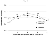
- the positive electrode active material layer may be uniformly formed in a length direction (width direction), and specifically, a loading level of the positive electrode active material layer may be uniform.
- a difference between a maximum loading value and a minimum loading value of the positive electrode active material layer at five or more positions having regular intervals in the length direction may be 10% or less, for example, 9% or less, 8% or less, or 6% or less, of a total loading average value. Accordingly, the above-described effect may be further improved.
- the loading may refer to a weight of a solid in a positive electrode active material slurry or a weight of a positive electrode active material layer of a positive electrode finally formed after a positive electrode slurry applied onto a positive electrode current collector is dried, and as a non-restrictive example, after a specimen is obtained by punching at least five points having regular intervals in a length direction (width direction) of the positive electrode in a circular shape, the weight of the solid in the positive electrode active material slurry or the positive electrode active material layer in the specimen may be measured.
- the positive electrode for a secondary battery fabricated according to the present invention may have an improved adhesive force to the substrate (current collector) due to the solid uniformly dispersed in the positive electrode active material layer.
- an adhesive force of the positive electrode active material layer to the current collector may be 0.35 N/cm or more, specifically 0.35 to 1.5 N/cm, and more specifically 0.45 to 0.8 N/cm.
- the present invention provides a secondary battery including: the positive electrode; a negative electrode; a separator positioned between the positive electrode and the negative electrode; and an electrolyte.
- the positive electrode fabricated according to the present invention may have an improved adhesive force to a substrate and uniformity of a thickness. Therefore, the secondary battery including the positive electrode may have further improved long-term stability.
- the negative electrode may include a current collector and a negative electrode active material layer disposed on the current collector.
- a material of the current collector may be copper or nickel, but is not limited thereto.
- a negative electrode active material may be used without limitation as long as it is a negative electrode active material usually used for the secondary battery.
- the negative electrode active material may be a carbon-based negative electrode active material, a silicon-based negative electrode active material, or a mixture thereof, but is not limited thereto.
- the carbon-based negative electrode active material may be one or more selected among artificial graphite, natural graphite, and hard carbon.
- the silicon-based negative electrode active material may be Si, SiO x (0 ⁇ x ⁇ 2), a Si-Q alloy (here, Q is an element selected from the group consisting of alkali metals, alkaline earth metals, Group XIII elements, Group XIV elements, Group XV elements, Group XVI elements, transition metals, rare earth elements, and combinations thereof and is not Si), a Si-carbon composite, or a mixture of at least one of them and SiO 2 .
- Q is an element selected from the group consisting of alkali metals, alkaline earth metals, Group XIII elements, Group XIV elements, Group XV elements, Group XVI elements, transition metals, rare earth elements, and combinations thereof and is not Si
- Q is an element selected from the group consisting of alkali metals, alkaline earth metals, Group XIII elements, Group XIV elements, Group XV elements, Group XVI elements, transition metals, rare earth elements, and combinations thereof and is not Si
- the separator is not particularly limited as long as it is a separator known in the art.
- the separator may be selected among glass fiber, polyester, polyethylene, polypropylene, polytetrafluoroethylene, or a combination thereof, may be in the form of a non-woven fabric or a woven fabric, and may optionally be used in a single-layer or multi-layer structure.
- the electrolyte includes a non-aqueous organic solvent and an electrolytic salt.
- the non-aqueous organic solvent may be ethylene carbonate (EC), propylene carbonate (PC), dimethyl carbonate (DMC), diethyl carbonate (DEC), ethylmethyl carbonate (EMC), 1,2-dimethoxyethane (DME), ⁇ -butyrolactone (BL), tetrahydrofuran (THF), 1,3-dioxolane (DOL), diethyl ester (DEE), methyl formate (MF), methyl propionate (MP), sulfolane (S), dimethyl sulfoxide (DMSO), acetonitrile (AN), or a mixture thereof, but is not limited thereto.
- the electrolytic salt is a material dissolved in the non-aqueous organic solvent, acting as a supply source of electrolytic metal ions in the secondary battery to enable a basic operation of the secondary battery, and promoting movement of the electrolytic metal ions between the positive electrode and the negative electrode.
- the electrolytic salt may be LiPF 6 , LiBF 4 , LiTFSI, LiSbF 6 , LiAsF 6 , LiClO 4 , LiCF 3 SO 3 , Li(CF 3 SO 2 ) 2 N, LiC 4 F 9 SO 3 , LiSbF 6 , LiAlO 4 , LiAlCl 4 , LiN(C x F 2x+1 SO 2 )(CyF 2 y +1 SO 2 ) (here, x and y are natural numbers), LiCl, LiI, or a mixture thereof, but is not limited thereto.
- the electrolyte salt may be a known material used in a concentration suitable for the purpose, and may further, if necessary, include a known solvent or additive in order to improve charging/discharging characteristics, flame-retardant characteristics, and the like.
- Step 1 preparation of positive electrode slurry
- NCM nickel cobalt manganese oxide
- NMP N-methyl pyrrolidone
- the positive electrode slurry (in a state in which it is heated to 80°C) prepared in Step 1 was applied onto an aluminum current collector (an aluminum foil having a thickness of 12 ⁇ m) using a slot die coater.
- the applied positive electrode slurry was left at 25°C for 5 seconds, cooled to 50°C, and dried in a drying furnace heated with hot air of 140°C for 1 minute to complete a positive electrode active material layer.
- a thickness of the positive electrode active material layer was set to 50 um.
- a positive electrode was fabricated in the same manner as in Example 1 except that drying was performed immediately after the heated positive electrode slurry was applied without performing a process of cooling the applied positive electrode slurry in Step 2 of Example 1.
- Example 2 The same method as in Example 1 was used except that the applied positive electrode slurry was dried and used as it is without performing a process of heating and cooling the positive electrode slurry in Step 2 of Example 1.
- Example 1 and Comparative Example 1 In order to analyze homogeneity of the positive electrode active material layers fabricated in Example 1 and Comparative Example 1, as illustrated in FIG. 2 , five points having regular intervals in a length direction of the positive electrode active material layers were selected and punched in a circular shape having a diameter of 38 mm, and weights of the positive electrode active material layers in punched specimens were then measured to analyze loading levels of the positive electrode active material layers in the positive electrodes. The weights of the positive electrode active material layers (loading levels of positive electrode active material layer compositions) measured for each position were divided by total weights of the positive electrode active material layers to be normalized, and results of the normalization are illustrated in FIG. 3 .
- Each viscosity of the slurry composition for a positive electrode before and after being heated and after being cooled was measured at a shear rate of 5s -1 at a corresponding temperature of each slurry composition using a rotary viscometer after preparing slurry compositions for a positive electrode at corresponding temperatures.
- the positive electrodes prepared in Example 1 and Comparative Example 1 were cut at a width of 18 mm and a length of 150 mm, and tapes having a width of 18 mm were attached to foil layers of the positive electrodes and then allowed to be sufficiently adhered to the foil layers with a roller having a load of 2 kg.
- the active material layers of the positive electrodes were attached to one side of a tensile tester using a double-sided tape.
- the tapes attached to the foil layers were fastened to the other side of the tensile tester, measurement of adhesive forces was performed, and measurement results are illustrated in Table 1.
- the positive electrode according to Example 1 was fabricated using the slurry composition for a positive electrode having the highest viscosity by containing a solid in a large amount (81.5 wt%), the positive electrode according to Example 1 had a high adhesive force to a substrate.
- the electrode according to Comparative Example 1 used a slurry composition for a positive electrode containing a solid content in the same large amount (81.5 wt%) as in Example 1, but was fabricated by drying a slurry composition for a positive electrode heated to have a decreased viscosity as it is immediately after the slurry composition for a positive electrode is applied without performing a cooling process unlike Embodiment 1, and thus had an adhesive force to a substrate lower than that in Example 1.
- a binder concentration was increased in a region adjacent to a surface of a positive electrode active material layer as compared with a region adjacent to the substrate owing to migration of a binder and a conductive material to an electrode surface layer due to a flow of a solvent in a case where the slurry composition for a positive electrode is dried as it is in a low-viscosity state.
- the slurry according to Comparative Example 2 contained a solid in the same amount as in Example 1 to have a high viscosity, but a process of decreasing a viscosity of the slurry by heating the slurry is not performed, such that the viscosity of the slurry is too high to fabricate a positive electrode. Therefore, an adhesive force to a substrate in Comparative Example 2 might not be evaluated.
- the concentration gradient of the binder and the conductive material in the thickness direction of the positive electrode active material layer of Example 1 did not substantially appear. It is analyzed that this is due to suppression of a migration phenomenon of the binder and the conductive material occurring in a slurry drying process.
- the slurry was dried immediately in a low-viscosity state, such that concentrations of the binder and the conductive material were increased in the region adjacent to the surface of the positive electrode active material layer as compared with the region adjacent to the substrate.
- Positive electrodes were fabricated in the same manner as in Example 1 except that the viscosity of the positive electrode slurry was changed as described in Table 2 by changing a content of the solid in the positive electrode slurry and a heating temperature of the positive electrode slurry at the time of preparing of the positive electrode slurry, in Step 1 of Example 1.
- the heating temperatures of Examples 2 to 4 were adjusted so that the viscosities of each slurry were 7,800 to 8,700 cP, and in Comparative Example 3, a slurry at room temperature (25°C) on which heating is not performed was used.
- Embodiments 3 and 4 showed a tendency to have adhesive forces somewhat lower than those of Examples 1 and 2 due to a relatively small content of a solid in the slurry, and a content of the solid in the slurry composition for a positive electrode was more than 74 parts by weight and 90 parts by weight or less based on 100 parts by weight of the slurry composition for a positive electrode.
- Positive electrodes were fabricated in the same manner as in Example 1 except that the drying process of the applied positive electrode slurry was changed as described in Table 3, in Step 2 of Example 1.
- a positive electrode was fabricated in the same manner as in Comparative Example 3 except that the drying process of Comparative Example 3 was changed as described in Table 3.
- a drying temperature is a low temperature of 140°C or less (Examples 1, 5, and 6)
- a drying time is increased in order to evaporate the solvent, but a migration phenomenon of the binder is suppressed, such that an adhesive force between the substrate and the active material layer is increased.
- a drying temperature is excessively high (Examples 7 and 8)
- active material particles are easily exposed to a surface of the solvent in the drying process due to rapid drying, and as a result, a migration phenomenon due to a capillary phenomenon is intensified, such that an adhesive force between the substrate and the active material layer is decreased.
- the high-viscosity slurry composition for a positive electrode is used, but the positive electrode is fabricated through a process of applying the high-viscosity slurry composition for a positive electrode onto the current collector in a state in which the viscosity of the high-viscosity slurry composition for a positive electrode is decreased by heating the high-viscosity slurry composition for a positive electrode, cooling the applied slurry composition for a positive electrode at room temperature again, and then drying the cooled s
Landscapes
- Chemical & Material Sciences (AREA)
- Chemical Kinetics & Catalysis (AREA)
- Electrochemistry (AREA)
- General Chemical & Material Sciences (AREA)
- Engineering & Computer Science (AREA)
- Manufacturing & Machinery (AREA)
- Materials Engineering (AREA)
- Inorganic Chemistry (AREA)
- Battery Electrode And Active Subsutance (AREA)
- Secondary Cells (AREA)
Abstract
Description
- This application claims priority under 35 U.S.C. §119 to
Korean Patent Application No. 10-2020-0097885, filed on Aug 5, 2020 - The following disclosure relates to a fabrication method of a positive electrode for a secondary battery and a secondary battery including the positive electrode.
- Recently, in accordance with an increase in a demand for electronic devices such as mobile devices, the development of technologies for weight reduction and miniaturization of electrochemical batteries (secondary batteries) for increasing portability of the electronic devices has been expanded. In addition to such a trend, in accordance with a global trend toward tightening regulations on fuel efficiency and exhaust gas of automobiles, the growth of an electric vehicle (EV) market has been accelerated, such that the development of high-output and large-capacity batteries to be used in such electric vehicles has been demanded.
- In such an electrochemical battery (secondary battery), generally, an electrode for the secondary battery is fabricated by applying an electrode slurry prepared by mixing an electrode active material, a conductive material, and a binder with each other in a solvent and dispersing the mixed electrode active material, conductive material, and binder using a strong shear force onto a current collector and then drying the electrode slurry. In this case, when a solvent used to dissolve the binder while dispersing the electrode active material and the conductive material remains after a drying process, the solvent causes an electrochemical side reaction in the secondary battery to adversely affect performance of the secondary battery. Meanwhile, a solvent flow from an inner portion of an electrode slurry layer to a surface of the electrode slurry layer occurs by a capillary force generated due to exposure of particles of the electrode active material or the like to a surface of the solvent in the drying process. As a result, the conductive material or the binder having a relatively smaller particle size than the electrode active material migrates, such that a large amount of conductive material or binder is distributed on a surface of the electrode. Such non-uniform distributions of the conductive material and the binder cause an increase in resistance of the secondary battery or a decrease in adhesive force between a substrate (current collector) and an electrode active material layer. Therefore, in order to solve the problems described above, a method of suppressing migration of small particles (the binder and the conductive material) in the electrode slurry while decreasing a content of the solvent remaining in the secondary battery by decreasing a content of the solvent in the electrode slurry to increase a viscosity of the electrode slurry has been studied. However, in a case where the content of the solvent in the electrode slurry is decreased to increase the viscosity of the electrode slurry, fluidity of the electrode slurry rapidly decreases, such that workability decreases, an electrode having a non-uniform thickness is fabricated, and an adhesive force between the current collector and the electrode active material layer in the electrode decreases. Therefore, research and development for solving a problem that an adhesive force of the substrate is decreased due to fluidity of a high-viscosity solvent while decreasing the content of the solvent are required.
- An object of the present invention is to solve a problem caused by migration of a conductive material and a binder due to a flow of a low-viscosity solvent at the time of drying a positive electrode slurry containing a positive electrode active material, the conductive material, the binder and a solvent, that is, a problem that an adhesive force between a current collector and a positive electrode active material layer is decreased, in a process of forming the positive electrode active material layer by applying the positive electrode slurry onto the current collector and drying the positive electrode slurry.
- In one general aspect, a fabrication method of a positive electrode for a secondary battery includes: (a) heating a slurry composition for a positive electrode containing a positive electrode active material, a binder, and a solvent to a temperature lower than a boiling point (Tb) of the solvent; (b) applying the heated slurry composition for a positive electrode onto a current collector; and (c) cooling the applied slurry composition for a positive electrode.
- A solid in the slurry composition for a positive electrode may be contained in an amount of more than 74 parts by weight and 90 parts by weight or less based on 100 parts by weight of the slurry composition for a positive electrode.
- A viscosity (A1) of the slurry composition for a positive electrode before being heated may be 13,000 to 80,000 cP.
- A temperature (T) of the heating of the slurry composition for a positive electrode may satisfy the following Relational Equation 1:

- The cooling may be performed at a temperature of 10 to 30°C for 1 to 60 seconds.
- The slurry composition for a positive electrode may satisfy the following
Relational Equations 2 and 3:

- The fabrication method of a positive electrode for a secondary battery may further include (d) drying the cooled slurry composition for a positive electrode. The drying may be performed at a temperature of 110°C or more and less than 145°C for 20 to 150 seconds.
- In another general aspect, a positive electrode for a secondary battery is fabricated by a fabrication method of a positive electrode for a secondary battery including: (a) heating a slurry composition for a positive electrode containing a positive electrode active material, a binder, and a solvent to a temperature lower than a boiling point (Tb) of the solvent; (b) applying the heated slurry composition for a positive electrode onto a current collector; and (c) cooling the applied slurry composition for a positive electrode, and includes: the current collector; and a positive electrode active material layer formed on the current collector and containing a positive electrode active material, a conductive material, and a binder.
- An adhesive force of the positive electrode active material layer to the current collector may be 0.35 N/cm or more.
- In the positive electrode, a difference between a maximum loading value and a minimum loading value of the positive electrode active material layer at five or more positions having regular intervals in a length direction may be 10% or less of a total loading average value.
- In still another general aspect, a secondary battery includes: a positive electrode; a negative electrode; a separator positioned between the positive electrode and the negative electrode; and an electrolyte, wherein the positive electrode is fabricated by a fabrication method of a positive electrode for a secondary battery including: (a) heating a slurry composition for a positive electrode containing a positive electrode active material, a binder, and a solvent to a temperature lower than a boiling point (Tb) of the solvent; (b) applying the heated slurry composition for a positive electrode onto a current collector; and (c) cooling the applied slurry composition for a positive electrode, and the positive electrode includes: the current collector; and a positive electrode active material layer formed on the current collector and containing a positive electrode active material, a conductive material, and a binder.
-
-
FIG. 1 is graphs illustrating results of distributions of binders in positive electrode active material layers according to a thickness direction through results obtained by analyzing cross sections of positive electrodes according to Example 1 and Comparative Example 1 by a scanning electron microscope-energy dispersive X-ray spectroscopy (SEM-EDS). -
FIG. 2 is a schematic diagram of a specimen obtained by selecting five points having regular intervals in a width direction of the positive electrode active material layer and punching the selected five points in a circular shape having a diameter of 38 mm in order to evaluate homogeneity of the positive electrode active material layer. -
FIG. 3 is graphs illustrating results obtained by dividing weights of positive electrode active material layers (loading levels of positive electrode active material layer compositions) measured for each position of positive electrodes according to Example 1 and Comparative Example 2 according to a width direction by total weights of the positive electrode active material layers to normalize the weights. - Various advantages and features of the present invention and methods accomplishing them will become apparent from the following detailed description of embodiments with reference to the accompanying drawings. However, the present invention is not limited to embodiments to be described below, but may be implemented in various different forms, these embodiments will be provided only in order to make the present invention complete and allow those skilled in the art to completely recognize the scope of the present invention, and the present invention will be defined by the scope of the claims. Hereinafter, detailed contents for carrying out the present invention will be described in detail with reference to the accompanying drawings. Throughout the drawings, the same reference numbers denote the same components, and "and/or" includes each and all of one or more combinations of the mentioned items.
- Unless defined otherwise, all terms (including technical and scientific terms) used in the present specification have the same meaning as meanings commonly understood by those skilled in the art to which the present invention pertains. Throughout the present specification, unless described to the contrary, "including" any component will be understood to imply the inclusion of other elements rather than the exclusion of other elements. In addition, a singular form includes a plural form unless specially described in the text.
- In the present specification, when an element such as a layer, a film, a region, or a plate is referred to as being "on" another element, it may be directly on another element or may be on another element with the other element interposed therebetween.
- In the present specification, a "viscosity" is a value measured at a shear rate of 5s-1 using a Brookfield rotary viscometer at a corresponding slurry temperature of each process, and has a tolerance of ±5 cP.
- An embodiment of the present invention provides a fabrication method of a positive electrode for a secondary battery, including: (a) heating a slurry composition for a positive electrode containing a positive electrode active material, a binder, and a solvent to a temperature lower than a boiling point (Tb) of the solvent; (b) applying the heated slurry composition for a positive electrode onto a current collector; and (c) cooling the applied slurry composition for a positive electrode.
- First, the slurry composition for a positive electrode containing the positive electrode active material, the binder, a conductive material, and the solvent is prepared.
- A solid (a positive electrode active material, a binder, and a conductive material) in the slurry composition for a positive electrode may be contained in an amount of more than 74 parts by weight, specifically more than 74 parts by weight and 90 parts by weight or less, and more specifically more than 74 parts by weight and 85 parts by weight or less, based on 100 parts by weight of the slurry composition for a positive electrode.
- In general, in a fabrication process of the positive electrode for a secondary battery, a slurry should have a viscosity of about 1,000 cp to 10,000 cp at 25°C in order to facilitate a slurry applying work and fabricate the positive electrode having a uniform thickness. However, in a case where the slurry composition for a positive electrode is prepared so that a content of the solid in the slurry composition for a positive electrode is 80 wt % (parts by weight) or more by decreasing a content of the solvent in the slurry composition for a positive electrode by a conventional method, a viscosity of the slurry becomes 53,000 cP or more, such that fluidity of the slurry decreases rapidly, resulting in lower workability, the positive electrode having a non-uniform thickness is fabricated, and an adhesive force between the current collector and a positive electrode active material layer in the positive electrode decreases. Therefore, the conventional slurry composition for a positive electrode contains a solid of about 74 wt% (parts by weight).
- On the other hand, in the present invention, a fluidity problem may be solved by heating a high-viscosity slurry for a positive electrode. However, in a case where the solid exceeds the above-mentioned weight range, when the slurry composition for a positive electrode is prepared, the slurry composition does not contain a minimum solvent required for dispersing solid particles, such that a shear force for dispersing the solid particles is not sufficiently at work, and the solid particles in the slurry composition may thus be applied onto the current collector in a state in which they are non-uniformly dispersed, and in a case where the solid is less than the above-mentioned weight range, fluidity of the slurry composition is sufficient, such that there is no need to apply a technology proposed in the present invention.
- A viscosity (A1) of the slurry composition for a positive electrode before being heated may be 13,000 to 80,000 cP, preferably 15,000 to 75,000 cP, 20,000 to 75,000 cP, or 25,000 to 75,000 cP, and more preferably 35,000 to 70,000 cP, 45,000 to 70,000 cP, 50,000 to 70,000 cP, or 55,000 to 70,000 cP, at 25°C.
- In a case where the viscosity (A1) of the slurry composition for a positive electrode is less than 13,000 cP at 25°C due to an increase in the content the solvent in the slurry composition for a positive electrode, an amount of the solvent contained in the slurry composition is large, such that an adhesion force between the positive electrode active material layer and the current collector is weakened due to a binder migration phenomenon, and long-term stability may thus be decreased.
- In a case where the viscosity (A1) of the slurry composition for a positive electrode exceeds 80,000 cP at 25°C, even though the content of the solid (particularly, the positive electrode active material and the binder) increases, an increase in the adhesive force between the positive electrode active material layer and the current collector is insignificant.
- In addition, as described below, the slurry composition for a positive electrode is applied onto the current collector in a state in which a viscosity of the slurry composition for a positive electrode is decreased by heating the slurry composition for a positive electrode, such that the binder in an applied film (applied slurry composition for a positive electrode) does not migrate to a surface of an electrode. Therefore, even though the slurry composition for a positive electrode contains the binder in a small amount, the slurry composition for a positive electrode may have an excellent adhesive force to a substrate (current collector). As a result, the slurry composition for a positive electrode may contain the binder in a smaller amount than a conventional slurry composition for a positive electrode. Therefore, the slurry composition for a positive electrode may contain the positive electrode active material in a larger amount than the conventional slurry composition for a positive electrode to provide a positive electrode having an improved electrode capacity.
- Specifically, a weight ratio (content ratio) of the positive electrode active material: the binder in the solid may be 1: 0.01 to 0.1, specifically 1: 0.01 to 0.05, and more specifically 1: 0.01 to 0.03.
- The positive electrode active material may be used without limitation as long as it is a positive electrode active material usually used for the secondary battery. As an example, the positive electrode active material may be a composite oxide of a metal selected from cobalt, manganese, nickel, and combinations thereof and lithium, but is not limited thereto.
- The binder is not particularly limited as long as it is a conventional binder capable of serving to bind the positive electrode active material to the current collector well while binding positive electrode active material particles to each other well. As an example, the binder may be polyvinyl alcohol, carboxymethyl cellulose, hydroxypropyl cellulose, diacetyl cellulose, polyvinyl chloride, carboxylated polyvinyl chloride, polyvinyl fluoride, a polymer including ethylene oxide, polyvinylpyrrolidone, polyurethane, polytetrafluoroethylene, polyvinylidene fluoride, polyethylene, polypropylene, styrene-butadiene rubber, acrylated styrene-butadiene rubber, epoxy resin, nylon, or the like, but is not limited thereto.
- The solvent may be at least one selected from the group consisting of an amine-based solvent such as N,N-dimethylaminopropylamine and diethylenetriamine; an ether-based solvent such as ethylene oxide and tetrahydrofuran; a ketone-based solvent such as methyl ethyl ketone; an ester-based solvent such as methyl acetate; and a polar aprotic solvent such as dimethylacetamide and N-methyl-2-pyrrolidone, but is not limited thereto.
- The conductive material is used to impart conductivity to the positive electrode, and is not particularly limited as long as it is a conventional electrically conductive material that does not cause a chemical change in the secondary battery. As an example, the conductive material may be natural graphite, artificial graphite, carbon black, acetylene black, ketjen black, carbon fiber, carbon nanotube, and combinations thereof, but is not limited thereto.
- The current collector may be stainless steel, aluminum, nickel, titanium, calcined carbon, or stainless steel whose surface is treated with carbon, nickel, titanium, silver, or the like, but is not limited thereto.
- Then, the prepared high-viscosity slurry composition for a positive electrode is heated to the temperature lower than the boiling point (Tb) of the solvent.
- Therefore, the high-viscosity slurry composition for a positive electrode is heated at the temperature lower than the boiling point, such that the viscosity of the slurry composition for a positive electrode may be decreased to a viscosity at which a work is easy and the positive electrode having a uniform thickness may be formed. Therefore, in the fabrication method of a positive electrode for a secondary battery according to the present invention, the high-viscosity slurry composition for a positive electrode containing the solid in a large amount is used, but the slurry composition for a positive electrode may be applied onto the current collector in a state in which the viscosity of the slurry composition for a positive electrode is decreased by heating the slurry composition for a positive electrode.
- However, in a case where a heating temperature of the slurry composition for a positive electrode is higher than or equal to the boiling point of the solvent, when the heated slurry composition for a positive electrode is transferred and stored, a strong vapor pressure is generated in a pipe or a storage container for transferring the slurry composition, which may cause a risk such as slurry leakage or explosion.
- Therefore, the heating may be performed at the temperature lower than the boiling point of the solvent contained in the slurry composition for a positive electrode.
- Specifically, the heating temperature (T) may satisfy the following
Relational Equation 1.
- In the
above Relational Equation 1, Tb is the boiling point of the solvent. - In
Relational Equation 1, 0.35 Tb < T < 0.9 Tb, preferably 0.4 Tb < T < 0.85 Tb, and more preferably 0.5 Tb < T < 0.8 Tb. - A viscosity (A2) of the heated slurry composition may be 6,000 to 10,000 cP, preferably 7,000 to 9,800 cP, and more preferably 7,500 to 9,600 cP at a corresponding temperature of each slurry composition.
- In step (b), the heated slurry composition for a positive electrode is applied onto the current collector. In this case, the applying may be performed without heating (raising a temperature of) the slurry composition and the substrate (current collector).
- As a non-restrictive example, the applying may be performed using any applying method known to be used for forming a film by generally applying a liquid phase. For example, the applying may be performed using spray coating, dip coating, spin coating, gravure coating, slot die coating, doctor blade coating, roll coating, inkjet printing, flexography printing, screen printing, electrohydrodynamic inkjet printing, micro contact printing, imprinting, reverse offset printing, bar-coating, gravure offset printing, and the like, but is not limited thereto.
- In step (c), the applied slurry composition for a positive electrode is cooled.
- The cooling is performed at a temperature of 10 to 30°C, specifically 10 to 25°C, and more specifically 15 to 25°C, for 1 to 60 seconds, specifically 1 to 30 seconds, and more specifically 3 to 7 seconds, immediately after the slurry composition for a positive electrode is heated and applied onto the current collector.
- The heated slurry composition for a positive electrode is cooled, such that the viscosity of the slurry composition for a positive electrode may be restored to a high viscosity again. Therefore, in the fabrication method of a positive electrode for a secondary battery according to the present invention, the high-viscosity slurry composition for a positive electrode containing the solid in the large amount is used, but the slurry composition for a positive electrode is applied onto the current collector in a state in which the viscosity of the slurry composition for a positive electrode is decreased by heating the slurry composition for a positive electrode, and the slurry composition for a positive electrode is cooled immediate after the slurry composition for a positive electrode is applied, such that the viscosity of the slurry composition for a positive electrode may be restored to the high viscosity again, and a migration phenomenon of the solid (the binder or the conductive material) occurring in a subsequent drying process may thus be suppressed. Therefore, the present invention may provide the positive electrode for a secondary battery having an improved adhesive force between the current collector and the positive electrode active material layer and prevent a problem such as a decrease in fluidity and non-uniformity of a thickness of the electrode that may be caused by the high viscosity.
- A viscosity (A3) of the cooled slurry composition may be 8,000 cP to 60,000 cP, preferably 10,000 cP to 55,000 cP, more preferably 13,000 cP to 50,000 cP, and even more preferably 35,000 cP to 45,000 cP at a corresponding temperature of each slurry composition.
- That is, the slurry composition for a positive electrode may satisfy the following Relational Equations 2' and 3' .


- In the above Relational Equations 2' and 3', A1 is the viscosity of the slurry composition for a positive electrode before being heated, A2 is the viscosity of the heated slurry composition for a positive electrode, and A3 is the viscosity of the cooled applied film (slurry composition for a positive electrode).
- However, even though the heated slurry composition for a positive electrode is cooled within a limited time, the heated slurry composition for a positive electrode may not be cooled to the temperature of the slurry composition for a positive electrode before being heated, and the viscosity of the slurry composition for a positive electrode restored by cooling the heated slurry composition for a positive electrode may thus be lower than that of the slurry composition for a positive electrode before being heated. Therefore, the above Relational Equations 2' and 3' may be organized as A2 < A3 ≤ A1, but are not limited thereto.
- In an embodiment, the viscosity of the slurry composition for a positive electrode is decreased to 1/3 or less after the slurry composition for a positive electrode is heated, and may be restored to a viscosity similar to an original viscosity again when the heated slurry composition for a positive electrode is cooled.
- That is, the above Relational Equations 2' and 3' may be organized again as the following
Relational Equations 
- In the
above Relational Equation 2, 1.8 ≤ A1/A2 ≤ 11, specifically 3 ≤ A1/A2 ≤ 10, and more specifically, 6 ≤ A1/A2 ≤ 7.
- In the
above Relational Equation 3, 1.3 ≤ A3/A2 ≤ 9, specifically 3 ≤ A3/A2 ≤ 7, and more specifically, 4 ≤ A3/A2 ≤ 5. - In addition, the fabrication method of a positive electrode for a secondary battery according to the present invention may further include (d) drying the cooled slurry composition for a positive electrode. In this case, the drying may be performed at a temperature of 100°C or more and less than 180°C, preferably 110 to 145°C, more preferably at 110 to 135°C, and more specifically 110 to 125°C, for 20 to 150 seconds, preferably 50 to 130 seconds, more preferably 70 to 120 seconds, and most preferably 90 to 110 seconds.
- Another embodiment of the present invention provides a positive electrode for a secondary battery fabricated according to the fabrication method described above and including: a current collector; and a positive electrode active material layer formed on the current collector and containing a positive electrode active material, a conductive material, and a binder.
- In general, in a case where the slurry composition for a positive electrode is simply heated to decrease the viscosity of the slurry composition for a positive electrode, is applied onto the current collector, and is then dried as it is in a high viscosity state, the conductive material and the binder light due to a particle size relatively smaller than that of the positive electrode active material may easily migrate toward a surface of a slurry layer for a positive electrode by a flow of the solvent. In this case, an adhesive force of the positive electrode active material layer to the substrate (current collector) may be significantly decreased.
- However, the positive electrode for a secondary battery fabricated according to the present invention is fabricated by applying the slurry composition for a positive electrode onto the current collector in a state in which the viscosity of the slurry composition for a positive electrode is decreased by heating the high-viscosity slurry composition for a positive electrode, cooling the applied slurry composition for a positive electrode immediately after the slurry composition for a positive electrode is applied to restore the viscosity of the slurry composition for a positive electrode to the high viscosity again, and then drying the cooled slurry composition for a positive electrode, and a migration phenomenon of the solid (the binder or the conductive material) may thus be suppressed.
- Therefore, the binder and the conductive material may not have a concentration gradient in a thickness direction of the positive electrode active material layer. In detail, in a case where the positive electrode active material layer is divided into a first region adjacent to the current collector, a second region positioned at a central portion of the positive electrode active material layer, and a third region adjacent to a surface of the positive electrode active material layer and is divided so that the respective regions have the same thickness, a concentration deviation of contents of the solids (the binders or the conductive materials) contained in the respective regions may be 0.4 wt% or less, specifically 0.01 to 0.4 wt%, and more specifically 0.05 to 0.35 wt%.
- Meanwhile, the first region, the second region, and the third region may have the same thickness, but the present invention is not limited thereto.
- In addition, the present invention is to solve a problem such as a decrease in fluidity of a slurry and non-uniformity of a thickness of the positive electrode that may be caused by using a high-viscosity slurry, and may improve fluidity of a slurry in spite of using a high-viscosity slurry for a positive electrode as compared with the related art to form the positive electrode at a uniform thickness (uniformly load the slurry) at the time of applying the slurry.
- In the positive electrode according to an embodiment of the present invention, the positive electrode active material layer may be uniformly formed in a length direction (width direction), and specifically, a loading level of the positive electrode active material layer may be uniform.
- Specifically, in the positive electrode, a difference between a maximum loading value and a minimum loading value of the positive electrode active material layer at five or more positions having regular intervals in the length direction may be 10% or less, for example, 9% or less, 8% or less, or 6% or less, of a total loading average value. Accordingly, the above-described effect may be further improved.
- In this case, the loading may refer to a weight of a solid in a positive electrode active material slurry or a weight of a positive electrode active material layer of a positive electrode finally formed after a positive electrode slurry applied onto a positive electrode current collector is dried, and as a non-restrictive example, after a specimen is obtained by punching at least five points having regular intervals in a length direction (width direction) of the positive electrode in a circular shape, the weight of the solid in the positive electrode active material slurry or the positive electrode active material layer in the specimen may be measured.
- Therefore, the positive electrode for a secondary battery fabricated according to the present invention may have an improved adhesive force to the substrate (current collector) due to the solid uniformly dispersed in the positive electrode active material layer.
- In a preferred embodiment, an adhesive force of the positive electrode active material layer to the current collector may be 0.35 N/cm or more, specifically 0.35 to 1.5 N/cm, and more specifically 0.45 to 0.8 N/cm.
- In addition, the present invention provides a secondary battery including: the positive electrode; a negative electrode; a separator positioned between the positive electrode and the negative electrode; and an electrolyte.
- In detail, the positive electrode fabricated according to the present invention may have an improved adhesive force to a substrate and uniformity of a thickness. Therefore, the secondary battery including the positive electrode may have further improved long-term stability.
- The negative electrode may include a current collector and a negative electrode active material layer disposed on the current collector. A material of the current collector may be copper or nickel, but is not limited thereto.
- A negative electrode active material may be used without limitation as long as it is a negative electrode active material usually used for the secondary battery. For example, the negative electrode active material may be a carbon-based negative electrode active material, a silicon-based negative electrode active material, or a mixture thereof, but is not limited thereto. The carbon-based negative electrode active material may be one or more selected among artificial graphite, natural graphite, and hard carbon. The silicon-based negative electrode active material may be Si, SiOx (0 < x < 2), a Si-Q alloy (here, Q is an element selected from the group consisting of alkali metals, alkaline earth metals, Group XIII elements, Group XIV elements, Group XV elements, Group XVI elements, transition metals, rare earth elements, and combinations thereof and is not Si), a Si-carbon composite, or a mixture of at least one of them and SiO2.
- The separator is not particularly limited as long as it is a separator known in the art. For example, the separator may be selected among glass fiber, polyester, polyethylene, polypropylene, polytetrafluoroethylene, or a combination thereof, may be in the form of a non-woven fabric or a woven fabric, and may optionally be used in a single-layer or multi-layer structure.
- The electrolyte includes a non-aqueous organic solvent and an electrolytic salt. The non-aqueous organic solvent may be ethylene carbonate (EC), propylene carbonate (PC), dimethyl carbonate (DMC), diethyl carbonate (DEC), ethylmethyl carbonate (EMC), 1,2-dimethoxyethane (DME), γ-butyrolactone (BL), tetrahydrofuran (THF), 1,3-dioxolane (DOL), diethyl ester (DEE), methyl formate (MF), methyl propionate (MP), sulfolane (S), dimethyl sulfoxide (DMSO), acetonitrile (AN), or a mixture thereof, but is not limited thereto. The electrolytic salt is a material dissolved in the non-aqueous organic solvent, acting as a supply source of electrolytic metal ions in the secondary battery to enable a basic operation of the secondary battery, and promoting movement of the electrolytic metal ions between the positive electrode and the negative electrode. As a non-restrictive example, in a case where an electrolytic metal is lithium, the electrolytic salt may be LiPF6, LiBF4, LiTFSI, LiSbF6, LiAsF6, LiClO4, LiCF3SO3, Li(CF3SO2)2N, LiC4F9SO3, LiSbF6, LiAlO4, LiAlCl4, LiN(CxF2x+1SO2)(CyF2y+1SO2) (here, x and y are natural numbers), LiCl, LiI, or a mixture thereof, but is not limited thereto. In addition, the electrolyte salt may be a known material used in a concentration suitable for the purpose, and may further, if necessary, include a known solvent or additive in order to improve charging/discharging characteristics, flame-retardant characteristics, and the like.
- 79.5 wt% of nickel cobalt manganese oxide (NCM) (specifically CSG131, Ni: Co: Mn=8: 1: 1), 1.2 wt% of polyvinylidene fluoride, 0.8 wt% of carbon black, and 18.5 w% of N-methyl pyrrolidone (NMP) were mixed with each other to prepare a positive electrode slurry (81.5 wt% of solid based on a total slurry), and the prepared positive electrode slurry was stirred in a stirring tank heated to 80°C for 30 minutes to maintain a temperature of the positive electrode slurry at 80°C.
- The positive electrode slurry (in a state in which it is heated to 80°C) prepared in
Step 1 was applied onto an aluminum current collector (an aluminum foil having a thickness of 12 µm) using a slot die coater. - Then, the applied positive electrode slurry was left at 25°C for 5 seconds, cooled to 50°C, and dried in a drying furnace heated with hot air of 140°C for 1 minute to complete a positive electrode active material layer.
- In this case, a thickness of the positive electrode active material layer was set to 50 um.
- A positive electrode was fabricated in the same manner as in Example 1 except that drying was performed immediately after the heated positive electrode slurry was applied without performing a process of cooling the applied positive electrode slurry in
Step 2 of Example 1. - The same method as in Example 1 was used except that the applied positive electrode slurry was dried and used as it is without performing a process of heating and cooling the positive electrode slurry in
Step 2 of Example 1. - Cross sections of positive electrodes prepared according to Example 1 and Comparative Example 1 were cut with an ion-milling device and fluorine distributions of binders in the positive electrodes were then measured through a scanning electron microscope-energy dispersive X-ray spectroscopy (SEM-EDS), and measurement results were compared and illustrated in
FIG. 1 . - In order to analyze homogeneity of the positive electrode active material layers fabricated in Example 1 and Comparative Example 1, as illustrated in
FIG. 2 , five points having regular intervals in a length direction of the positive electrode active material layers were selected and punched in a circular shape having a diameter of 38 mm, and weights of the positive electrode active material layers in punched specimens were then measured to analyze loading levels of the positive electrode active material layers in the positive electrodes. The weights of the positive electrode active material layers (loading levels of positive electrode active material layer compositions) measured for each position were divided by total weights of the positive electrode active material layers to be normalized, and results of the normalization are illustrated inFIG. 3 . - As illustrated in
FIG. 3 , it can be seen that when the positive electrode active material layer is fabricated, in a case where the positive electrode slurry is applied in a state in which a viscosity of the positive electrode slurry is decreased to about 9,500 cp by heating the positive electrode slurry (Example 1), a difference between loading values (maximum value - minimum value) of the positive electrode active material layer was 6%, which is very low, of a total loading average value measured at five points, while in a case where the positive electrode slurry is applied in a state in which it has a high viscosity of 64,000 cp (Comparative Example 2), a difference between loading values of the positive electrode active material layer was 15% of a total loading average value measured at five points, which shows a non-uniform distribution in which a loading level of a central portion is high and a loading level of an outer side portion is low. - Each viscosity of the slurry composition for a positive electrode before and after being heated and after being cooled was measured at a shear rate of 5s-1 at a corresponding temperature of each slurry composition using a rotary viscometer after preparing slurry compositions for a positive electrode at corresponding temperatures.
- The positive electrodes prepared in Example 1 and Comparative Example 1 were cut at a width of 18 mm and a length of 150 mm, and tapes having a width of 18 mm were attached to foil layers of the positive electrodes and then allowed to be sufficiently adhered to the foil layers with a roller having a load of 2 kg. The active material layers of the positive electrodes were attached to one side of a tensile tester using a double-sided tape. The tapes attached to the foil layers were fastened to the other side of the tensile tester, measurement of adhesive forces was performed, and measurement results are illustrated in Table 1.
[Table 1] Viscosity (cP) of positive electrode slurry Adhesive force (N/cm) Before being heated (@ 25°C) After being heated (@ 80°C) After being cooled (@ 50°C) Example 1 64,000 9,500 42,000 0.52 Comparative Example 1 64,000 9,500 - 0.39 Comparative Example 2 64.000 - - - - Referring to Table 1, when looking at a change in a viscosity of the slurry composition for a positive electrode according to a temperature, it can be seen that the viscosity of the slurry composition for a positive electrode was decreased immediately after the slurry composition was heated and then restored to a high viscosity after the slurry composition was cooled.
- It can be seen that even though the positive electrode according to Example 1 was fabricated using the slurry composition for a positive electrode having the highest viscosity by containing a solid in a large amount (81.5 wt%), the positive electrode according to Example 1 had a high adhesive force to a substrate. It can be seen that the electrode according to Comparative Example 1 used a slurry composition for a positive electrode containing a solid content in the same large amount (81.5 wt%) as in Example 1, but was fabricated by drying a slurry composition for a positive electrode heated to have a decreased viscosity as it is immediately after the slurry composition for a positive electrode is applied without performing a cooling process unlike
Embodiment 1, and thus had an adhesive force to a substrate lower than that in Example 1. This is because a binder concentration was increased in a region adjacent to a surface of a positive electrode active material layer as compared with a region adjacent to the substrate owing to migration of a binder and a conductive material to an electrode surface layer due to a flow of a solvent in a case where the slurry composition for a positive electrode is dried as it is in a low-viscosity state. - Meanwhile, the slurry according to Comparative Example 2 contained a solid in the same amount as in Example 1 to have a high viscosity, but a process of decreasing a viscosity of the slurry by heating the slurry is not performed, such that the viscosity of the slurry is too high to fabricate a positive electrode. Therefore, an adhesive force to a substrate in Comparative Example 2 might not be evaluated.
- In addition, referring to
FIG. 1 , it could be confirmed that the concentration gradient of the binder and the conductive material in the thickness direction of the positive electrode active material layer of Example 1 did not substantially appear. It is analyzed that this is due to suppression of a migration phenomenon of the binder and the conductive material occurring in a slurry drying process. On the other hand, in Comparative Example 1, the slurry was dried immediately in a low-viscosity state, such that concentrations of the binder and the conductive material were increased in the region adjacent to the surface of the positive electrode active material layer as compared with the region adjacent to the substrate. - Positive electrodes were fabricated in the same manner as in Example 1 except that the viscosity of the positive electrode slurry was changed as described in Table 2 by changing a content of the solid in the positive electrode slurry and a heating temperature of the positive electrode slurry at the time of preparing of the positive electrode slurry, in
Step 1 of Example 1. In this case, the heating temperatures of Examples 2 to 4 were adjusted so that the viscosities of each slurry were 7,800 to 8,700 cP, and in Comparative Example 3, a slurry at room temperature (25°C) on which heating is not performed was used. - Evaluation of interfacial adhesive forces between the active material layers and the current collectors and evaluation of viscosities were performed in the same manner as in Evaluation Example 1, and evaluations results were illustrated in Table 2.
[Table 2] Division (Content (%) of solid Viscosity (cP) of positive electrode slurry Adhesive force (N/cm) A1 before being heated A2 after being heated A3 after being cooled Viscosit y ratio (A1/A2) Viscosit y ratio (A3/A2) Example 1 81.5 64,000 9,500 42,000 6.7 4.4 0.52 Example 2 80.0 53,000 7,800 37,000 6.8 4.7 0.48 Example 3 76.0 13,000 8,700 9,800 1.5 1.1 0.35 Example 4 78.0 18,000 8,500 12,000 2.1 1.4 0.36 Comparative Example 3 74.0 2,600 2,600 2,600 1.0 1.0 0.32 - Referring to Table 2, it could be seen that in a case of Examples 1 and 2 having a preferable content range of solid, fluidity of a solvent was decreased due to a high viscosity of the applied slurry, such that a migration phenomenon of the binder in a drying process is suppressed, and as a result, an adhesive force between the substrate and the active material layer was increased.
- On the other hand, it could be confirmed that in Comparative Example 3, an adhesive force was very low, and it was analyzed that the positive electrode was formed using a slurry at room temperature that is not subjected to a heating step, a content of the solid in the slurry was not sufficiently high, such that the slurry contained a solvent in a relatively large amount, and a concentration gradient in which a content of the binder is higher in a surface of the positive electrode due to a migration phenomenon of the binder under the same drying condition was formed.
- Meanwhile, it could be confirmed that
Embodiments - Positive electrodes were fabricated in the same manner as in Example 1 except that the drying process of the applied positive electrode slurry was changed as described in Table 3, in
Step 2 of Example 1. - A positive electrode was fabricated in the same manner as in Comparative Example 3 except that the drying process of Comparative Example 3 was changed as described in Table 3.
- Evaluation of interfacial adhesive forces between the active material layers and the current collectors was performed in the same manner as in Evaluation Example 1, and evaluations results were illustrated in Table 3.
[Table 3] Division (Content (%) of solid Drying condition Adhesive force (N) Drying temperature (°C) Drying time (second) Example 1 81.5 140 60 0.52 Example 5 81.5 130 80 0.54 Example 6 81.5 120 100 0.55 Example 7 81.5 150 45 0.48 Example 8 81.5 160 30 0.46 Comparative Example 4 74 120 100 0.32 - Referring to Table 3, it can be confirmed that in a case where a drying temperature is a low temperature of 140°C or less (Examples 1, 5, and 6), a drying time is increased in order to evaporate the solvent, but a migration phenomenon of the binder is suppressed, such that an adhesive force between the substrate and the active material layer is increased. On the other hand, it can be confirmed that in a case where a drying temperature is excessively high (Examples 7 and 8), active material particles are easily exposed to a surface of the solvent in the drying process due to rapid drying, and as a result, a migration phenomenon due to a capillary phenomenon is intensified, such that an adhesive force between the substrate and the active material layer is decreased. In addition, it can be confirmed that in a case of a conventional positive electrode slurry in which a content of a solid is 74 wt% (Comparative Example 4), an adhesive force between the substrate and the active material layer is the lowest in spite of performing the same drying process as in Example 6, which is a condition in which the adhesive strength is the most excellent.
- In the fabrication method of a positive electrode for a secondary battery according to the present invention, in order to solve a problem of a conventional fabrication method of a positive electrode using a low-viscosity slurry composition for a positive electrode, that is, a problem that the adhesive force between the current collector and the positive electrode active material layer is decreased due to migration of the conductive material and the binder to the surface of the positive electrode active material layer owing to a flow of a low-viscosity solvent at the time of drying the slurry composition, the high-viscosity slurry composition for a positive electrode is used, but the positive electrode is fabricated through a process of applying the high-viscosity slurry composition for a positive electrode onto the current collector in a state in which the viscosity of the high-viscosity slurry composition for a positive electrode is decreased by heating the high-viscosity slurry composition for a positive electrode, cooling the applied slurry composition for a positive electrode at room temperature again, and then drying the cooled slurry composition for a positive electrode. Therefore, it is possible to prevent a problem such as the decrease in fluidity and the non-uniformity of the thickness of the positive electrode that may be caused by the high viscosity while providing the positive electrode for a secondary battery having an improved adhesive force between the current collector and the positive electrode active material layer.
- The present invention has been described hereinabove, but the present invention is not limited to the above embodiments, but may be implemented in various different forms, and those skilled in the art to which the present invention pertains may understand that the present invention may be implemented in other specific forms without changing the technical spirit or essential features of the present invention. Therefore, it is to be understood that the embodiments described above are illustrative rather than being restrictive in all aspects.
Claims (12)
- A fabrication method of a positive electrode for a secondary battery, comprising:(a) heating a slurry composition for a positive electrode containing a positive electrode active material, a binder, and a solvent to a temperature lower than a boiling point (Tb) of the solvent;(b) applying the heated slurry composition for a positive electrode onto a current collector; and(c) cooling the applied slurry composition for a positive electrode.
- The fabrication method of a positive electrode for a secondary battery of claim 1, wherein a solid in the slurry composition for a positive electrode is contained in an amount of more than 74 parts by weight and 90 parts by weight or less based on 100 parts by weight of the slurry composition for a positive electrode.
- The fabrication method of a positive electrode for a secondary battery of claim 1, wherein a viscosity (A1) of the slurry composition for a positive electrode before being heated is 13,000 to 80,000 cP.
- The fabrication method of a positive electrode for a secondary battery of claim 1, wherein a temperature (T) of the heating of the slurry composition for a positive electrode satisfies the following Relational Equation 1:

- The fabrication method of a positive electrode for a secondary battery of claim 1, wherein the cooling is performed at a temperature of 10 to 30°C for 1 to 60 seconds.
- The fabrication method of a positive electrode for a secondary battery of claim 1, wherein the slurry composition for a positive electrode satisfies the following Relational Equations 2 and 3:
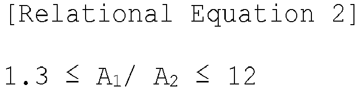

- The fabrication method of a positive electrode for a secondary battery of claim 1, further comprising (d) drying the cooled slurry composition for a positive electrode.
- The fabrication method of a positive electrode for a secondary battery of claim 7, wherein the drying is performed at a temperature of 110°C or more and less than 145°C for 20 to 150 seconds.
- A positive electrode for a secondary battery, fabricated by a fabrication method of a positive electrode for a secondary battery including: (a) heating a slurry composition for a positive electrode containing a positive electrode active material, a binder, and a solvent to a temperature lower than a boiling point (Tb) of the solvent; (b) applying the heated slurry composition for a positive electrode onto a current collector; and (c) cooling the applied slurry composition for a positive electrode, the positive electrode comprising:the current collector; anda positive electrode active material layer formed on the current collector and containing a positive electrode active material, a conductive material, and a binder.
- The positive electrode for a secondary battery of claim 9, wherein an adhesive force of the positive electrode active material layer to the current collector is 0.35 N/cm or more.
- The positive electrode for a secondary battery of claim 9, wherein in the positive electrode, a difference between a maximum loading value and a minimum loading value of the positive electrode active material layer at five or more positions having regular intervals in a length direction is 10% or less of a total loading average value.
- A secondary battery comprising:a positive electrode;a negative electrode;a separator positioned between the positive electrode and the negative electrode; andan electrolyte,wherein the positive electrode is fabricated by a fabrication method of a positive electrode for a secondary battery including: (a) heating a slurry composition for a positive electrode containing a positive electrode active material, a binder, and a solvent to a temperature lower than a boiling point (Tb) of the solvent; (b) applying the heated slurry composition for a positive electrode onto a current collector; and (c) cooling the applied slurry composition for a positive electrode, andthe positive electrode includes:the current collector; anda positive electrode active material layer formed on the current collector and containing a positive electrode active material, a conductive material, and a binder.
Applications Claiming Priority (1)
| Application Number | Priority Date | Filing Date | Title |
|---|---|---|---|
| KR1020200097885A KR20220017652A (en) | 2020-08-05 | 2020-08-05 | Fabrication method of positive electrode for battery and secondary battery including same |
Publications (1)
| Publication Number | Publication Date |
|---|---|
| EP3951921A1 true EP3951921A1 (en) | 2022-02-09 |
Family
ID=77179923
Family Applications (1)
| Application Number | Title | Priority Date | Filing Date |
|---|---|---|---|
| EP21189192.4A Pending EP3951921A1 (en) | 2020-08-05 | 2021-08-02 | Fabrication method of positive electrode for secondary battery and secondary battery including the positive electrode |
Country Status (5)
| Country | Link |
|---|---|
| US (1) | US12341179B2 (en) |
| EP (1) | EP3951921A1 (en) |
| JP (1) | JP2022031222A (en) |
| KR (1) | KR20220017652A (en) |
| CN (1) | CN114068876A (en) |
Families Citing this family (4)
| Publication number | Priority date | Publication date | Assignee | Title |
|---|---|---|---|---|
| CN115493716B (en) * | 2022-08-16 | 2025-04-25 | 湖北亿纬动力有限公司 | Method for determining slurry discharge temperature and readable storage medium |
| JP7756399B2 (en) * | 2022-09-22 | 2025-10-20 | 三桜工業株式会社 | Electrode manufacturing method |
| KR102838987B1 (en) * | 2022-09-28 | 2025-07-24 | 한국에너지기술연구원 | Method for manufacturing a dry electrode that include rapid low-temperature freezing and rapid solvent removal, and electrode manufactured through the same |
| CN121219850A (en) * | 2023-05-31 | 2025-12-26 | 株式会社Lg化学 | Methods for preparing positive electrode slurry compositions and methods for preparing positive electrodes |
Citations (3)
| Publication number | Priority date | Publication date | Assignee | Title |
|---|---|---|---|---|
| CN104692352A (en) * | 2013-12-05 | 2015-06-10 | 中国电子科技集团公司第十八研究所 | Method for surface coating of lithium ion battery anode material with nanoscale iron phosphate |
| CN106299269A (en) * | 2016-08-18 | 2017-01-04 | 山东精工电子科技有限公司 | A kind of lithium ion battery anode glue size preparation method |
| CN107611338A (en) * | 2017-08-25 | 2018-01-19 | 金川集团股份有限公司 | The preparation method of Snap-type cell positive slurry used in a kind of check and evaluation material electrical property |
Family Cites Families (10)
| Publication number | Priority date | Publication date | Assignee | Title |
|---|---|---|---|---|
| KR980012685A (en) * | 1996-07-09 | 1998-04-30 | 홍건희 | Method for manufacturing electrode of lithium ion secondary battery |
| JP5834898B2 (en) * | 2011-12-27 | 2015-12-24 | 日産自動車株式会社 | Electrode manufacturing method and electrode manufacturing apparatus |
| JP6168148B2 (en) * | 2013-07-31 | 2017-07-26 | 日産自動車株式会社 | Solid solution lithium-containing transition metal oxide, and non-aqueous electrolyte secondary battery using the solid solution lithium-containing transition metal oxide as a positive electrode |
| US20160118666A1 (en) * | 2014-10-24 | 2016-04-28 | Semiconductor Energy Laboratory Co., Ltd. | Storage battery electrode, manufacturing method thereof, storage battery, and electronic device |
| KR102040511B1 (en) * | 2016-09-09 | 2019-11-05 | 주식회사 엘지화학 | Electrode coating apparatus |
| CN109873119B (en) * | 2017-12-01 | 2022-02-01 | 中国科学院大连化学物理研究所 | Drying method for preparing electrode based on blade coating method, electrode and application thereof |
| KR102507632B1 (en) * | 2018-06-08 | 2023-03-08 | 주식회사 엘지에너지솔루션 | Separator coating slurry composition for secondary battery and seperator for secondary battery comprising the same |
| CN109301250B (en) * | 2018-09-17 | 2020-07-17 | 内蒙古蒙集新碳材有限公司 | Lithium battery negative electrode slurry and preparation process thereof |
| CN111354949B (en) * | 2018-12-24 | 2021-12-07 | 宁德时代新能源科技股份有限公司 | Lithium ion battery |
| CN210700857U (en) * | 2019-09-20 | 2020-06-09 | 般若涅利(北京)装备技术有限公司 | Lithium ion battery pole piece coating machine |
-
2020
- 2020-08-05 KR KR1020200097885A patent/KR20220017652A/en not_active Ceased
-
2021
- 2021-08-02 CN CN202110880114.XA patent/CN114068876A/en active Pending
- 2021-08-02 EP EP21189192.4A patent/EP3951921A1/en active Pending
- 2021-08-05 JP JP2021128649A patent/JP2022031222A/en active Pending
- 2021-08-05 US US17/395,141 patent/US12341179B2/en active Active
Patent Citations (3)
| Publication number | Priority date | Publication date | Assignee | Title |
|---|---|---|---|---|
| CN104692352A (en) * | 2013-12-05 | 2015-06-10 | 中国电子科技集团公司第十八研究所 | Method for surface coating of lithium ion battery anode material with nanoscale iron phosphate |
| CN106299269A (en) * | 2016-08-18 | 2017-01-04 | 山东精工电子科技有限公司 | A kind of lithium ion battery anode glue size preparation method |
| CN107611338A (en) * | 2017-08-25 | 2018-01-19 | 金川集团股份有限公司 | The preparation method of Snap-type cell positive slurry used in a kind of check and evaluation material electrical property |
Also Published As
| Publication number | Publication date |
|---|---|
| CN114068876A (en) | 2022-02-18 |
| JP2022031222A (en) | 2022-02-18 |
| KR20220017652A (en) | 2022-02-14 |
| US12341179B2 (en) | 2025-06-24 |
| US20220045308A1 (en) | 2022-02-10 |
Similar Documents
| Publication | Publication Date | Title |
|---|---|---|
| US12341179B2 (en) | Fabrication method of positive electrode for secondary battery and secondary battery including the positive electrode | |
| EP3863084B1 (en) | Negative electrode and secondary battery including same | |
| US12176513B2 (en) | Multilayer electrode for secondary battery and fabrication method thereof | |
| EP3038193B1 (en) | Negative active material and lithium battery including negative active material | |
| US11502302B2 (en) | Process for producing a composite material | |
| EP4044274A1 (en) | Anode and secondary battery comprising same | |
| KR102134299B1 (en) | Negative electrode active material slurry for lithium secondary battery, and preparing method thereof | |
| EP4109593A1 (en) | Anode and secondary battery comprising same | |
| EP4020632A1 (en) | Anode active material, preparation method therefor, and anode and secondary battery which comprise same | |
| EP4184652A1 (en) | Method for charging and discharging secondary battery | |
| EP3863105B1 (en) | Secondary battery | |
| EP4261936B1 (en) | Negative electrode and secondary battery including the same | |
| EP3951920A1 (en) | Fabrication method of negative electrode for secondary battery and secondary battery including negative electrode | |
| EP3951955A1 (en) | Binder composition for anode, anode, and secondary battery | |
| EP4037010A1 (en) | Electrode for secondary battery, and secondary battery comprising same | |
| JP2000021407A (en) | Lithium secondary battery | |
| KR20190001564A (en) | Method of preparing cathode slurry for lithium secondary battery and cathodes for lithium secondary battery manufactured therefrom | |
| EP3863082A1 (en) | Method for manufacturing negative electrode active material for secondary battery, negative electrode for secondary battery, and lithium secondary battery comprising same | |
| EP4651236A1 (en) | Cathode active material, cathode containing same, and lithium secondary battery | |
| EP4525067A1 (en) | Electrode for secondary battery, method for manufacturing same, and secondary battery including same | |
| EP4625545A1 (en) | Positive electrode active material, positive electrode comprising same, and lithium secondary battery | |
| EP4557387A1 (en) | Method for manufacturing electrode for secondary battery | |
| EP4708388A1 (en) | Positive electrode active material, and positive electrode and lithium secondary battery comprising same | |
| EP4435882A1 (en) | Positive electrode for lithium secondary battery, and lithium secondary battery comprising same | |
| EP4738468A1 (en) | Cathode active material for lithium secondary battery and lithium secondary battery comprising same |
Legal Events
| Date | Code | Title | Description |
|---|---|---|---|
| PUAI | Public reference made under article 153(3) epc to a published international application that has entered the european phase |
Free format text: ORIGINAL CODE: 0009012 |
|
| STAA | Information on the status of an ep patent application or granted ep patent |
Free format text: STATUS: REQUEST FOR EXAMINATION WAS MADE |
|
| 17P | Request for examination filed |
Effective date: 20210802 |
|
| AK | Designated contracting states |
Kind code of ref document: A1 Designated state(s): AL AT BE BG CH CY CZ DE DK EE ES FI FR GB GR HR HU IE IS IT LI LT LU LV MC MK MT NL NO PL PT RO RS SE SI SK SM TR |
|
| RAP1 | Party data changed (applicant data changed or rights of an application transferred) |
Owner name: SK ON CO., LTD. |
|
| P01 | Opt-out of the competence of the unified patent court (upc) registered |
Effective date: 20230602 |
|
| STAA | Information on the status of an ep patent application or granted ep patent |
Free format text: STATUS: EXAMINATION IS IN PROGRESS |
|
| 17Q | First examination report despatched |
Effective date: 20260331 |