EP3951826A1 - Arc-extinguishing unit structure for direct current air circuit breaker - Google Patents
Arc-extinguishing unit structure for direct current air circuit breaker Download PDFInfo
- Publication number
- EP3951826A1 EP3951826A1 EP20782115.8A EP20782115A EP3951826A1 EP 3951826 A1 EP3951826 A1 EP 3951826A1 EP 20782115 A EP20782115 A EP 20782115A EP 3951826 A1 EP3951826 A1 EP 3951826A1
- Authority
- EP
- European Patent Office
- Prior art keywords
- arc
- magnet
- arc guide
- guide
- fixing means
- Prior art date
- Legal status (The legal status is an assumption and is not a legal conclusion. Google has not performed a legal analysis and makes no representation as to the accuracy of the status listed.)
- Granted
Links
Images





Classifications
-
- H—ELECTRICITY
- H01—ELECTRIC ELEMENTS
- H01H—ELECTRIC SWITCHES; RELAYS; SELECTORS; EMERGENCY PROTECTIVE DEVICES
- H01H73/00—Protective overload circuit-breaking switches in which excess current opens the contacts by automatic release of mechanical energy stored by previous operation of a hand reset mechanism
- H01H73/02—Details
- H01H73/18—Means for extinguishing or suppressing arc
-
- H—ELECTRICITY
- H01—ELECTRIC ELEMENTS
- H01H—ELECTRIC SWITCHES; RELAYS; SELECTORS; EMERGENCY PROTECTIVE DEVICES
- H01H9/00—Details of switching devices, not covered by groups H01H1/00 - H01H7/00
- H01H9/30—Means for extinguishing or preventing arc between current-carrying parts
- H01H9/34—Stationary parts for restricting or subdividing the arc, e.g. barrier plate
- H01H9/36—Metal parts
- H01H9/362—Mounting of plates in arc chamber
-
- H—ELECTRICITY
- H01—ELECTRIC ELEMENTS
- H01H—ELECTRIC SWITCHES; RELAYS; SELECTORS; EMERGENCY PROTECTIVE DEVICES
- H01H33/00—High-tension or heavy-current switches with arc-extinguishing or arc-preventing means
- H01H33/02—Details
- H01H33/04—Means for extinguishing or preventing arc between current-carrying parts
- H01H33/18—Means for extinguishing or preventing arc between current-carrying parts using blow-out magnet
- H01H33/182—Means for extinguishing or preventing arc between current-carrying parts using blow-out magnet using permanent magnets
-
- H—ELECTRICITY
- H01—ELECTRIC ELEMENTS
- H01H—ELECTRIC SWITCHES; RELAYS; SELECTORS; EMERGENCY PROTECTIVE DEVICES
- H01H31/00—Air-break switches for high tension without arc-extinguishing or arc-preventing means
- H01H31/02—Details
-
- H—ELECTRICITY
- H01—ELECTRIC ELEMENTS
- H01H—ELECTRIC SWITCHES; RELAYS; SELECTORS; EMERGENCY PROTECTIVE DEVICES
- H01H33/00—High-tension or heavy-current switches with arc-extinguishing or arc-preventing means
- H01H33/02—Details
- H01H33/53—Cases; Reservoirs, tanks, piping or valves, for arc-extinguishing fluid; Accessories therefor, e.g. safety arrangements, pressure relief devices
-
- H—ELECTRICITY
- H01—ELECTRIC ELEMENTS
- H01H—ELECTRIC SWITCHES; RELAYS; SELECTORS; EMERGENCY PROTECTIVE DEVICES
- H01H9/00—Details of switching devices, not covered by groups H01H1/00 - H01H7/00
- H01H9/30—Means for extinguishing or preventing arc between current-carrying parts
-
- H—ELECTRICITY
- H01—ELECTRIC ELEMENTS
- H01H—ELECTRIC SWITCHES; RELAYS; SELECTORS; EMERGENCY PROTECTIVE DEVICES
- H01H9/00—Details of switching devices, not covered by groups H01H1/00 - H01H7/00
- H01H9/30—Means for extinguishing or preventing arc between current-carrying parts
- H01H9/44—Means for extinguishing or preventing arc between current-carrying parts using blow-out magnet
- H01H9/443—Means for extinguishing or preventing arc between current-carrying parts using blow-out magnet using permanent magnets
Definitions
- the present disclosure relates to an arc-extinguishing structure for a direct-current air circuit breaker.
- an air circuit breaker (ACB) is installed in a low voltage distribution line and performs transmission, switching, switching, and stop of low voltage system power in a planned manner, and uses air as extinguishing medium to break a circuit in an event of abnormalities such as overcurrent, short circuit and ground fault and thus protect people and a load.
- ACB air circuit breaker
- a direct-current air circuit breaker includes an extinguishing part and an electrical conducting part inside the circuit breaker.
- a mechanical part operates via a relay such that a fixed contact and a movable contact are removed from each other.
- an arc is generated when the fixed contact and the movable contact are removed from each other. Accordingly, the arc as generated travels from the fixed contact and the movable contact to a cooling plate via a Lorentz force (an arc magnetic field-based driving force) generated orthogonally by arc current and a magnetic flux density and is cooled and extinguished by the cooling plate.
- a Lorentz force an arc magnetic field-based driving force
- an arc guide is coupled to an arc chute assay, and the arc guide serves to guide the arc to a center of the cooling plate so that arc extinguishing occurs quickly.
- One aspect of the present disclosure has a purpose to provide an arc-extinguishing structure for a direct-current air circuit breaker that generates an arc magnetic field-based driving force using a magnetic field of a magnet, and quickly discharges the arc to an extinguishing unit.
- Another aspect of the present disclosure has a purpose to provide an arc-extinguishing structure for a direct-current air circuit breaker in which upper and lower portions of a magnet have different poles in a vertical direction in which the arc guide is positioned below a grid in an arc chute assay, thereby preventing reverse flow of the arc.
- Another aspect of the present disclosure has a purpose to provide an arc-extinguishing structure for a direct-current air circuit breaker that may maximize a magnetic field magnitude of the magnet inserted into the arc guide to maximize an arc magnetic field-based driving force.
- Another aspect of the present disclosure has a purpose to provide an arc-extinguishing structure for a direct-current air circuit breaker that may secure small current interruption performance while shortening an arc duration.
- An arc-extinguishing structure for a direct-current air circuit breaker includes a plurality of grids; both opposing side plates respectively coupled to both opposing sides of each of the plurality of grids so that the plurality of the grids are arranged horizontally and spaced from each other; a discharge cover positioned on tops of the side plates and the plurality of grids; each arc guide coupled to each of the side plates such that the guide is positioned below the plurality of grids; and each magnet coupled to each arc guide, wherein the magnet had upper and lower portions in a vertical arrangement of the plurality of grids and the arc guide, wherein the upper and lower portions have different poles.
- each magnet receiving groove is defined in the arc guide, wherein the magnet is received in the groove, wherein the magnet extends in the arrangement direction of the grids, wherein the magnet receiving groove extends in the arrangement direction of the grids.
- side plate fixing means is defined in the arc guide in an area of the magnet receiving groove, wherein arc guide fixing means corresponding to the side plate fixing means is defined in the side plate.
- each of the side plate fixing means and the arc guide fixing means is embodied as a through-hole.
- the magnet extends in a longitudinal direction of the arc guide, and a mounting hole corresponding to the through-hole is defined in the magnet, wherein a fastener fastens the arc guide fixing means, the mounting hole, and the side plate fixing means to each other, wherein the fastener fastens the arc guide to the side plate while the magnet is received in the magnet receiving groove.
- an upper portion of the magnet is magnetized as a S pole and a lower portion thereof is magnetized as an N pole.
- the guide plate of the arc guide in which the magnet receiving groove is defined is formed such that a dimension of one side of the guide plate is larger than a dimension of an opposite side thereof, wherein a dimension of one side of the magnet receiving groove is larger than a dimension of an opposite side thereof, wherein a dimension of one side of the magnet coupled to the magnet receiving hole is larger than a dimension of an opposite side thereof.
- the magnet includes a plurality of magnets, wherein the arc guide has a plurality of magnet receiving grooves for receiving the plurality of the magnets, wherein side plate fixing means is defined in the arc guide in an area of each of the magnet receiving grooves, wherein arc guide fixing means corresponding to the side plate fixing means is defined in the side plate.
- each of the side plate fixing means and the arc guide fixing means is embodied as a through-hole.
- a fastener fastens the arc guide fixing means and the side plate fixing means to each other, wherein the fastener fastens the arc guide to the side plate while the magnet is received in the magnet receiving groove.
- each magnet is magnetized as a S pole and a lower portion thereof is magnetized as an N pole.
- the arc guide extends in a longitudinal direction from one side to an opposite side thereof and, further, extends downwards from one side
- the magnet receiving groove includes a first magnet receiving groove extending downwards from one side of the arc guide, and a second magnet receiving groove extending from one side of the arc guide to the opposite side thereof, wherein the magnet includes a first magnet extending downwards in a corresponding manner to the first magnet receiving groove, and a second magnet extending in the longitudinal direction in a corresponding manner to the second magnet receiving groove.
- the grid has a downwardly-inclined portion at a bottom of the grid, wherein the downwardly-inclined portion has an inner side face inclined outwardly as the portion extends from a center toward each of both opposing ends, wherein the arc guide further includes a guide plate having an upwardly-inclined portion facing toward the downwardly-inclined portion.
- the arc magnetic field-based driving force may be generated by the magnetic field of the magnet, and thus, the arc may be quickly discharged to the extinguishing structure.
- the upper and lower portions of the magnet have different poles in a vertical direction in which the arc guide is positioned below a grid in an arc chute assay, thereby preventing reverse flow of the arc.
- the arc-extinguishing structure may maximize a magnetic field magnitude of the magnet inserted into the arc guide to maximize the arc magnetic field-based driving force.
- the arc-extinguishing structure may secure small current interruption performance while shortening an arc duration.
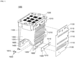
- FIG. 1 is a configuration diagram schematically showing an arc-extinguishing structure for a direct-current air circuit breaker according to a first embodiment of the present disclosure.
- FIG. 2 is a schematic diagram showing an arc guide in the arc-extinguishing structure shown in FIG. 1 .
- FIG. 3 is a schematic diagram showing a magnet in the arc-extinguishing structure shown in FIG. 1 .
- An arc-extinguishing structure 1000 may allow a direct-current air circuit breaker used in various direct-current interruption facilities including solar power generation facilities to secure small current interruption performance.
- the arc-extinguishing structure 1000 includes side plates 1100, a grid 1200, a discharge cover 1300, an arc guide 1400 and a magnet 1500.
- the grid 1200 acts as a cooling plate that divides and cools incoming arc.
- the grid 1200 includes a plurality of grids spaced apart from each other and disposed between both opposing side plates 1100 positioned at both opposing sides of the discharge cover 1300.
- a fixing protrusion 1210 is formed on each of both opposing ends of the grid 1200, and a through-hole 1110 corresponding to the fixing protrusion 1210 is formed in each side plate 1100.
- the grid 1200 has a downwardly inclined portion 1220 so that a lower portion thereof extends from a center toward each of both opposing ends in an inclined manner.
- the discharge cover 1300 is coupled to a top of each of the side plates 1100, and the arc guide 1400 is coupled to a bottom of each of the side plates 1100.
- arc guide fixing means 1120 and discharge cover coupling means 1130 are formed in each of the side plates 1100.
- the discharge cover 1300 is positioned on tops of the side plates 1100 and the plurality of grids.
- Side plate coupling means 1310 corresponding to the discharge cover coupling means 1130 of the side plate is formed on the discharge cover 1300.
- FIG. 1 shows an example in which the side plate coupling means 1310 is embodied as a protrusion, and the discharge cover coupling means 1130 is embodied as a through-hole.
- the arc guide 1400 is fixed to the side plate so as to be positioned under the plurality of grids 1200.
- the arc guide 1400 includes a magnet receiving groove 1410, a guide plate 1420 and side plate fixing means 1430.
- the magnet receiving groove 1410 has a shape corresponding to that of the magnet 1500.
- the magnet receiving groove 1410 extends in the arrangement direction of the grids 1200, and the guide plate 1420 extends toward the grid 1200.
- the side plate fixing means 1430 may be formed in the magnet receiving groove 1410.
- the guide plate 1420 may be embodied as an upwardly inclined portion corresponding to the downwardly inclined portion 1220 of the grid 1200.
- the side plate fixing means 1430 is constructed for fixing the arc guide 1400 to the side plate 1100, and corresponds to the arc guide fixing means 1120. Further, each of the arc guide fixing means 1120 and the side plate fixing means 1430 may be embodied as a through-hole.
- the magnet 1500 extends in a longitudinal direction of the arc guide 1400 as the arrangement direction of the grids. Different poles are magnetized at upper and lower portions of the magnet in an orthogonal direction to the extension direction, that is, an arrangement direction of the grid 1200 and the arc guide 1400.
- the upper portion is magnetized as a S pole as a first pole 1500a
- a lower portion is magnetized as a N pole as a second pole 1500b.
- the magnetic field-based driving force increases to a maximum level, thereby enabling rapid cooling and extinguishing of the arc.
- a mounting hole 1510 is formed in the magnet 1500.
- the mounting hole 1510 is formed to correspond to the side plate fixing means and the arc guide fixing means embodied as the through-hole.
- the guide plate of the arc guide 1400 in which the magnet receiving groove 1410 is formed has a dimension of one side thereof which is larger than a dimension of the opposite side thereof. This is based on an overall structure of the arc-extinguishing structure 1000 mounted on the circuit breaker.
- the magnet receiving groove 1410 is formed so that a dimension of one side thereof is larger than a dimension of the opposite side thereof in a corresponding manner to the above structure.
- the magnet 1500 coupled to the magnet receiving hole 1410 is formed so that a dimension of one side thereof is larger than a dimension of the opposite side thereof in a corresponding manner to the above structure.
- the arc-extinguishing structure 1000 further includes a fastener 1600.
- the fastener 1600 combines the arc guide fixing means 1120, the mounting hole 1510 and the side plate fixing means 1430 to each other.
- the arc guide may be fixed to the side plate in a state in which the magnet is coupled to the arc guide.
- the fastener 1600 may have an insulating layer 1610 made of silicon or the like coated thereon.
- FIG. 4 is a configuration diagram schematically showing an arc-extinguishing structure for a direct-current air circuit breaker according to a second embodiment of the present disclosure.
- FIG. 5 is a schematic diagram showing an arc guide in the arc-extinguishing structure shown in FIG. 4 .
- FIG. 6 is a schematic diagram showing a magnet in the arc-extinguishing structure shown in FIG. 4 .
- an arc-extinguishing structure 2000 differs from the arc-extinguishing structure 1000 shown in FIG. 1 to FIG. 3 only in terms of the magnet and the magnet receiving groove 1410 accommodating therein the magnet.
- the arc-extinguishing structure 2000 includes both side plates 2100, a grid 2200, a discharge cover 2300, an arc guide 2400, and magnets 2500a and 2500b.
- the magnet includes a first magnet 2500a and a second magnet 2500b.
- side plates 2100, the grid 2200, and the discharge cover 2300 are respectively identical with the side plates 1100, the grid 2200, and the discharge cover 2300 of the arc-extinguishing structure 1000 according to the first embodiment as described above, and detailed descriptions thereof will be omitted.
- the arc guide 2400 has a magnet receiving groove 2410, a guide plate 2420, and side plate fixing means 2430.
- the magnet receiving groove 2410 includes a first magnet receiving groove 2410a into and to which the first magnet 2500a is inserted and coupled and a second magnet receiving groove 2410b into and to which the second magnet 2500b is inserted and coupled.
- each of the first magnet receiving groove 2410a and the second magnet receiving groove 2410b is formed in an area where the side plate fixing means 2430 is not formed.
- the arc guide 2400 is formed to extend in the longitudinal direction from one side to the opposite side and at the same time, to extend downward from one side. Accordingly, the arc guide 2400 may have the first magnet receiving groove 2410a extending from one side downwardly and the second magnet receiving groove 2410b extending from one side to the opposite side.
- the first magnet 2500a extends downward so as to correspond to the first magnet receiving groove 2410a, while the second magnet 2500b extends in a longitudinal direction so as to correspond to the second magnet receiving groove 2410b.
- a upper portion of each of the first poles 2500a' and 2500b' is magnetized as the S pole, while a lower portion of each of the second poles 2500a" and 2500b" is magnetized as the N pole.
- the arc guide 2400 is fixed to the side plate 2100 by fastening a fastener 2600 to the arc guide fixing means 2120 and the side plate fixing means 2430.
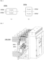
- FIG. 7 is a block diagram schematically showing a direct-current air circuit breaker having an arc-extinguishing structure according to the present disclosure.
- the arc-extinguishing structure 1000 or 2000, a fixed conductor assay 3000 and a movable conductor assay 4000 are mounted on a body of the direct-current air circuit breaker.
- the movable conductor assay 4000 is mounted to face toward the fixed conductor assay 3000.
- the arc-extinguishing structure 1000 or 2000 is positioned above the fixed conductor assay 3000 and the movable conductor assay 4000 to extinguish the arc generated when the contacts are removed from each other.
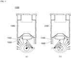
- FIG. 8 is a schematic first use state diagram of the arc-extinguishing structure according to the first embodiment in the direct-current air circuit breaker shown in FIG. 7 .
- FIG. 9 is a schematic second use state diagram of the arc-extinguishing structure according to the first embodiment in the direct-current air circuit breaker shown in FIG. 7 .
- the direct-current air circuit breaker performs the small current interruption, the magnetic field is uniformly distributed around the magnet.
- a magnitude of the arc magnetic field-based driving force is determined based on a magnetic field magnitude of the magnet, and a direction of the force is orthogonal to a direction of the magnetic field and a current direction.
- the arc magnetic field-based driving force F acts toward the grid 1200 as shown by an arrow, based on the magnetic field distribution and a connection direction of the small current. Further, (a) in FIG. 9 shows the driving force F when the current is output in an extension direction of the arc guide 1400, while (b) in FIG. 9 shows the driving force F when the current is input in the extension direction of the arc guide 1400.
- the arc magnetic field-based driving force acts in a lateral direction of the grid 1200, based on the magnetic field distribution and the small current connection direction.
- the arc magnetic field-based driving force F is generated in this way, not only arc extinguishing occurs quickly, but also arc backflow does not occur and arc stagnation does not occur.
- FIG. 10 is a schematic first use state diagram of the arc-extinguishing structure according to the second embodiment in the direct-current air circuit breaker shown in FIG. 7 .
- FIG. 11 is a schematic second use state diagram of the arc-extinguishing structure according to the second embodiment in the direct-current air circuit breaker shown in FIG. 7 .
- the direct-current air circuit breaker performs the small current interruption, the magnetic field is uniformly distributed around the magnet.
- a magnitude of the arc magnetic field-based driving force is determined based on a magnetic field magnitude of the magnet, and a direction of the force is orthogonal to a direction of the magnetic field and a current direction.
- the arc magnetic field-based driving force F acts toward the grid 2200 as shown by an arrow, based on the magnetic field distribution and a connection direction of the small current. Further, (a) in FIG. 11 shows the driving force F when the current is output in an extension direction of the arc guide 2400, while (b) in FIG. 11 shows the driving force F when the current is input in the extension direction of the arc guide 2400.
- the arc magnetic field-based driving force acts in a lateral direction of the grid 2200, based on the magnetic field distribution and the small current connection direction.
- the arc magnetic field-based driving force F is generated in this way, not only arc extinguishing occurs quickly, but also arc backflow does not occur and arc stagnation does not occur.
- the arc extinguishing may be achieved quickly, the arc backflow does not occur, and the arc stagnation does not occur.
- the magnet may have a maximum size to maximize the arc magnetic field-based driving force F.
- the arc-extinguishing structure 2000 may be easily installed regardless of the side plate fixing means 2430, and thus, assembly and productivity thereof may be improved.
Landscapes
- Arc-Extinguishing Devices That Are Switches (AREA)
- Breakers (AREA)
Abstract
Description
- The present disclosure relates to an arc-extinguishing structure for a direct-current air circuit breaker.
- In general, an air circuit breaker (ACB) is installed in a low voltage distribution line and performs transmission, switching, switching, and stop of low voltage system power in a planned manner, and uses air as extinguishing medium to break a circuit in an event of abnormalities such as overcurrent, short circuit and ground fault and thus protect people and a load.
- More specifically, a direct-current air circuit breaker according to a prior art includes an extinguishing part and an electrical conducting part inside the circuit breaker. When abnormal current occurs due to overcurrent, short circuit, or ground fault of a line, a mechanical part operates via a relay such that a fixed contact and a movable contact are removed from each other.
- Further, an arc is generated when the fixed contact and the movable contact are removed from each other. Accordingly, the arc as generated travels from the fixed contact and the movable contact to a cooling plate via a Lorentz force (an arc magnetic field-based driving force) generated orthogonally by arc current and a magnetic flux density and is cooled and extinguished by the cooling plate.
- Further, an arc guide is coupled to an arc chute assay, and the arc guide serves to guide the arc to a center of the cooling plate so that arc extinguishing occurs quickly.
- However, in an event of interruption of a small current based on IEC 60947-3 ANNEX D standard, a very small magnetic field-based driving force is generated from the arc due to the small current and magnetic field. Further, arc stagnation occurs between the fixed contact and the movable contact.
- Further, high temperature arc stagnation causes serious structural and electrical damage to the extinguishing part and the conducting part, and thus causes deterioration of performance of the breaker and equipment accidents.
- One aspect of the present disclosure has a purpose to provide an arc-extinguishing structure for a direct-current air circuit breaker that generates an arc magnetic field-based driving force using a magnetic field of a magnet, and quickly discharges the arc to an extinguishing unit.
- Another aspect of the present disclosure has a purpose to provide an arc-extinguishing structure for a direct-current air circuit breaker in which upper and lower portions of a magnet have different poles in a vertical direction in which the arc guide is positioned below a grid in an arc chute assay, thereby preventing reverse flow of the arc.
- Another aspect of the present disclosure has a purpose to provide an arc-extinguishing structure for a direct-current air circuit breaker that may maximize a magnetic field magnitude of the magnet inserted into the arc guide to maximize an arc magnetic field-based driving force.
- Another aspect of the present disclosure has a purpose to provide an arc-extinguishing structure for a direct-current air circuit breaker that may secure small current interruption performance while shortening an arc duration.
- An arc-extinguishing structure for a direct-current air circuit breaker according to one embodiment of the present disclosure includes a plurality of grids; both opposing side plates respectively coupled to both opposing sides of each of the plurality of grids so that the plurality of the grids are arranged horizontally and spaced from each other; a discharge cover positioned on tops of the side plates and the plurality of grids; each arc guide coupled to each of the side plates such that the guide is positioned below the plurality of grids; and each magnet coupled to each arc guide, wherein the magnet had upper and lower portions in a vertical arrangement of the plurality of grids and the arc guide, wherein the upper and lower portions have different poles.
- In one implementation of the arc-extinguishing structure, each magnet receiving groove is defined in the arc guide, wherein the magnet is received in the groove, wherein the magnet extends in the arrangement direction of the grids, wherein the magnet receiving groove extends in the arrangement direction of the grids.
- In one implementation of the arc-extinguishing structure, side plate fixing means is defined in the arc guide in an area of the magnet receiving groove, wherein arc guide fixing means corresponding to the side plate fixing means is defined in the side plate.
- In one implementation of the arc-extinguishing structure, each of the side plate fixing means and the arc guide fixing means is embodied as a through-hole.
- In one implementation of the arc-extinguishing structure, the magnet extends in a longitudinal direction of the arc guide, and a mounting hole corresponding to the through-hole is defined in the magnet, wherein a fastener fastens the arc guide fixing means, the mounting hole, and the side plate fixing means to each other, wherein the fastener fastens the arc guide to the side plate while the magnet is received in the magnet receiving groove.
- In one implementation of the arc-extinguishing structure, an upper portion of the magnet is magnetized as a S pole and a lower portion thereof is magnetized as an N pole.
- In one implementation of the arc-extinguishing structure, the guide plate of the arc guide in which the magnet receiving groove is defined is formed such that a dimension of one side of the guide plate is larger than a dimension of an opposite side thereof, wherein a dimension of one side of the magnet receiving groove is larger than a dimension of an opposite side thereof, wherein a dimension of one side of the magnet coupled to the magnet receiving hole is larger than a dimension of an opposite side thereof.
- In one implementation of the arc-extinguishing structure, the magnet includes a plurality of magnets, wherein the arc guide has a plurality of magnet receiving grooves for receiving the plurality of the magnets, wherein side plate fixing means is defined in the arc guide in an area of each of the magnet receiving grooves, wherein arc guide fixing means corresponding to the side plate fixing means is defined in the side plate.
- In one implementation of the arc-extinguishing structure, each of the side plate fixing means and the arc guide fixing means is embodied as a through-hole.
- In one implementation of the arc-extinguishing structure,
a fastener fastens the arc guide fixing means and the side plate fixing means to each other, wherein the fastener fastens the arc guide to the side plate while the magnet is received in the magnet receiving groove. - In one implementation of the arc-extinguishing structure, an upper portion of each magnet is magnetized as a S pole and a lower portion thereof is magnetized as an N pole.
- In one implementation of the arc-extinguishing structure, the arc guide extends in a longitudinal direction from one side to an opposite side thereof and, further, extends downwards from one side, wherein the magnet receiving groove includes a first magnet receiving groove extending downwards from one side of the arc guide, and a second magnet receiving groove extending from one side of the arc guide to the opposite side thereof, wherein the magnet includes a first magnet extending downwards in a corresponding manner to the first magnet receiving groove, and a second magnet extending in the longitudinal direction in a corresponding manner to the second magnet receiving groove.
- In one implementation of the arc-extinguishing structure, the grid has a downwardly-inclined portion at a bottom of the grid, wherein the downwardly-inclined portion has an inner side face inclined outwardly as the portion extends from a center toward each of both opposing ends, wherein the arc guide further includes a guide plate having an upwardly-inclined portion facing toward the downwardly-inclined portion.
- According to the present disclosure, the arc magnetic field-based driving force may be generated by the magnetic field of the magnet, and thus, the arc may be quickly discharged to the extinguishing structure. According to another aspect of the present disclosure, the upper and lower portions of the magnet have different poles in a vertical direction in which the arc guide is positioned below a grid in an arc chute assay, thereby preventing reverse flow of the arc. Further, the arc-extinguishing structure may maximize a magnetic field magnitude of the magnet inserted into the arc guide to maximize the arc magnetic field-based driving force. Further, the arc-extinguishing structure may secure small current interruption performance while shortening an arc duration.
-
-
FIG. 1 is a configuration diagram schematically showing an arc-extinguishing structure for a direct-current air circuit breaker according to a first embodiment of the present disclosure. -
FIG. 2 is a schematic diagram showing an arc guide in the arc-extinguishing structure shown inFIG. 1 . -
FIG. 3 is a schematic diagram showing a magnet in the arc-extinguishing structure shown inFIG. 1 . -
FIG. 4 is a configuration diagram schematically showing an arc-extinguishing structure for a direct-current air circuit breaker according to a second embodiment of the present disclosure. -
FIG. 5 is a schematic diagram showing an arc guide in the arc-extinguishing structure shown inFIG. 4 . -
FIG. 6 is a schematic diagram showing a magnet in the arc-extinguishing structure shown inFIG. 4 . -
FIG. 7 is a block diagram schematically showing a direct-current air circuit breaker equipped with an arc-extinguishing structure according to the present disclosure. -
FIG. 8 is a schematic first use state diagram of the arc-extinguishing structure according to the first embodiment in the direct-current air circuit breaker shown inFIG. 7 . -
FIG. 9 is a schematic second use state diagram of the arc-extinguishing structure according to the first embodiment in the direct-current air circuit breaker shown inFIG. 7 . -
FIG. 10 is a schematic first use state diagram of the arc-extinguishing structure according to the second embodiment in the direct-current air circuit breaker shown inFIG. 7 . -
FIG. 11 is a schematic second use state diagram of the arc-extinguishing structure according to the second embodiment in the direct-current air circuit breaker shown inFIG. 7 . -
FIG. 1 is a configuration diagram schematically showing an arc-extinguishing structure for a direct-current air circuit breaker according to a first embodiment of the present disclosure.FIG. 2 is a schematic diagram showing an arc guide in the arc-extinguishing structure shown inFIG. 1 .FIG. 3 is a schematic diagram showing a magnet in the arc-extinguishing structure shown inFIG. 1 . - An arc-
extinguishing structure 1000 may allow a direct-current air circuit breaker used in various direct-current interruption facilities including solar power generation facilities to secure small current interruption performance. - As shown, the arc-
extinguishing structure 1000 includesside plates 1100, agrid 1200, adischarge cover 1300, anarc guide 1400 and amagnet 1500. - More specifically, the
grid 1200 acts as a cooling plate that divides and cools incoming arc. Thegrid 1200 includes a plurality of grids spaced apart from each other and disposed between bothopposing side plates 1100 positioned at both opposing sides of thedischarge cover 1300. - For this purpose, a
fixing protrusion 1210 is formed on each of both opposing ends of thegrid 1200, and a through-hole 1110 corresponding to thefixing protrusion 1210 is formed in eachside plate 1100. - The
grid 1200 has a downwardlyinclined portion 1220 so that a lower portion thereof extends from a center toward each of both opposing ends in an inclined manner. - The
discharge cover 1300 is coupled to a top of each of theside plates 1100, and thearc guide 1400 is coupled to a bottom of each of theside plates 1100. - To this end, arc guide fixing means 1120 and discharge cover coupling means 1130 are formed in each of the
side plates 1100. - The
discharge cover 1300 is positioned on tops of theside plates 1100 and the plurality of grids. Side plate coupling means 1310 corresponding to the discharge cover coupling means 1130 of the side plate is formed on thedischarge cover 1300. -
FIG. 1 shows an example in which the side plate coupling means 1310 is embodied as a protrusion, and the discharge cover coupling means 1130 is embodied as a through-hole. - The
arc guide 1400 is fixed to the side plate so as to be positioned under the plurality ofgrids 1200. - Further, the
arc guide 1400 includes amagnet receiving groove 1410, aguide plate 1420 and side plate fixing means 1430. Themagnet receiving groove 1410 has a shape corresponding to that of themagnet 1500. - Further, the
magnet receiving groove 1410 extends in the arrangement direction of thegrids 1200, and theguide plate 1420 extends toward thegrid 1200. - The side plate fixing means 1430 may be formed in the
magnet receiving groove 1410. - The
guide plate 1420 may be embodied as an upwardly inclined portion corresponding to the downwardlyinclined portion 1220 of thegrid 1200. - The side plate fixing means 1430 is constructed for fixing the
arc guide 1400 to theside plate 1100, and corresponds to the arc guide fixing means 1120. Further, each of the arc guide fixing means 1120 and the side plate fixing means 1430 may be embodied as a through-hole. - The
magnet 1500 extends in a longitudinal direction of thearc guide 1400 as the arrangement direction of the grids. Different poles are magnetized at upper and lower portions of the magnet in an orthogonal direction to the extension direction, that is, an arrangement direction of thegrid 1200 and thearc guide 1400. - In an example, in
FIG. 3 , the upper portion is magnetized as a S pole as afirst pole 1500a, and a lower portion is magnetized as a N pole as asecond pole 1500b. - As described above, as the magnet is mounted and coupled to the
arc guide 1400, the magnetic field-based driving force increases to a maximum level, thereby enabling rapid cooling and extinguishing of the arc. - Further, a mounting
hole 1510 is formed in themagnet 1500. The mountinghole 1510 is formed to correspond to the side plate fixing means and the arc guide fixing means embodied as the through-hole. - Further, the guide plate of the
arc guide 1400 in which themagnet receiving groove 1410 is formed has a dimension of one side thereof which is larger than a dimension of the opposite side thereof. This is based on an overall structure of the arc-extinguishingstructure 1000 mounted on the circuit breaker. - Further, the
magnet receiving groove 1410 is formed so that a dimension of one side thereof is larger than a dimension of the opposite side thereof in a corresponding manner to the above structure. Themagnet 1500 coupled to themagnet receiving hole 1410 is formed so that a dimension of one side thereof is larger than a dimension of the opposite side thereof in a corresponding manner to the above structure. - The arc-extinguishing
structure 1000 further includes afastener 1600. Thefastener 1600 combines the arc guide fixing means 1120, the mountinghole 1510 and the side plate fixing means 1430 to each other. Thus, the arc guide may be fixed to the side plate in a state in which the magnet is coupled to the arc guide. - Further, the
fastener 1600 may have an insulatinglayer 1610 made of silicon or the like coated thereon. -
FIG. 4 is a configuration diagram schematically showing an arc-extinguishing structure for a direct-current air circuit breaker according to a second embodiment of the present disclosure.FIG. 5 is a schematic diagram showing an arc guide in the arc-extinguishing structure shown inFIG. 4 .FIG. 6 is a schematic diagram showing a magnet in the arc-extinguishing structure shown inFIG. 4 . - As shown, an arc-extinguishing
structure 2000 differs from the arc-extinguishingstructure 1000 shown inFIG. 1 to FIG. 3 only in terms of the magnet and themagnet receiving groove 1410 accommodating therein the magnet. - More specifically, the arc-extinguishing
structure 2000 includes bothside plates 2100, agrid 2200, adischarge cover 2300, anarc guide 2400, andmagnets - The magnet includes a
first magnet 2500a and asecond magnet 2500b. - In addition, the
side plates 2100, thegrid 2200, and thedischarge cover 2300 are respectively identical with theside plates 1100, thegrid 2200, and thedischarge cover 2300 of the arc-extinguishingstructure 1000 according to the first embodiment as described above, and detailed descriptions thereof will be omitted. - The
arc guide 2400 has amagnet receiving groove 2410, aguide plate 2420, and side plate fixing means 2430. Themagnet receiving groove 2410 includes a firstmagnet receiving groove 2410a into and to which thefirst magnet 2500a is inserted and coupled and a secondmagnet receiving groove 2410b into and to which thesecond magnet 2500b is inserted and coupled. - Further, each of the first
magnet receiving groove 2410a and the secondmagnet receiving groove 2410b is formed in an area where the side plate fixing means 2430 is not formed. - The
arc guide 2400 is formed to extend in the longitudinal direction from one side to the opposite side and at the same time, to extend downward from one side. Accordingly, thearc guide 2400 may have the firstmagnet receiving groove 2410a extending from one side downwardly and the secondmagnet receiving groove 2410b extending from one side to the opposite side. - The
first magnet 2500a extends downward so as to correspond to the firstmagnet receiving groove 2410a, while thesecond magnet 2500b extends in a longitudinal direction so as to correspond to the secondmagnet receiving groove 2410b. - Upper and lower portions of each of the
first magnet 2500a and thesecond magnet 2500b are magnetized to have different poles in an orthogonal direction to the extension direction of thearc guide 2400, that is, in an arrangement direction of thegrid 2200 and thearc guide 2400. - In an example of
FIG. 6 , a upper portion of each of thefirst poles 2500a' and 2500b' is magnetized as the S pole, while a lower portion of each of thesecond poles 2500a" and 2500b" is magnetized as the N pole. - Further, while the
first magnet 2500a is inserted into the firstmagnet receiving groove 2410a, and thesecond magnet 2500b is inserted into the secondmagnet receiving groove 2410b, thearc guide 2400 is fixed to theside plate 2100 by fastening afastener 2600 to the arc guide fixing means 2120 and the side plate fixing means 2430. -
FIG. 7 is a block diagram schematically showing a direct-current air circuit breaker having an arc-extinguishing structure according to the present disclosure. - As shown, the arc-extinguishing
structure conductor assay 3000 and amovable conductor assay 4000 are mounted on a body of the direct-current air circuit breaker. - Further, the
movable conductor assay 4000 is mounted to face toward the fixedconductor assay 3000. The arc-extinguishingstructure conductor assay 3000 and themovable conductor assay 4000 to extinguish the arc generated when the contacts are removed from each other. -
FIG. 8 is a schematic first use state diagram of the arc-extinguishing structure according to the first embodiment in the direct-current air circuit breaker shown inFIG. 7 .FIG. 9 is a schematic second use state diagram of the arc-extinguishing structure according to the first embodiment in the direct-current air circuit breaker shown inFIG. 7 . - As shown in
FIG. 8 , when themagnet 1500 is installed on thearc guide 1400, a magnetic field is distributed as shown by an arrow in small current interruption. - Further, when the direct-current air circuit breaker performs the small current interruption, the magnetic field is uniformly distributed around the magnet.
- Further, as shown in
FIG. 9 , a magnitude of the arc magnetic field-based driving force is determined based on a magnetic field magnitude of the magnet, and a direction of the force is orthogonal to a direction of the magnetic field and a current direction. - That is, the arc magnetic field-based driving force F acts toward the
grid 1200 as shown by an arrow, based on the magnetic field distribution and a connection direction of the small current. Further, (a) inFIG. 9 shows the driving force F when the current is output in an extension direction of thearc guide 1400, while (b) inFIG. 9 shows the driving force F when the current is input in the extension direction of thearc guide 1400. - Eventually, when the small current interruption occurs, the arc magnetic field-based driving force acts in a lateral direction of the
grid 1200, based on the magnetic field distribution and the small current connection direction. as the arc magnetic field-based driving force F is generated in this way, not only arc extinguishing occurs quickly, but also arc backflow does not occur and arc stagnation does not occur. -
FIG. 10 is a schematic first use state diagram of the arc-extinguishing structure according to the second embodiment in the direct-current air circuit breaker shown inFIG. 7 .FIG. 11 is a schematic second use state diagram of the arc-extinguishing structure according to the second embodiment in the direct-current air circuit breaker shown inFIG. 7 . - As shown in
FIG. 10 , when themagnet 2500 is installed on thearc guide 2400, the magnetic field is distributed as shown in an arrow in the small current interruption. - Further, when the direct-current air circuit breaker performs the small current interruption, the magnetic field is uniformly distributed around the magnet.
- Further, as shown in
FIG. 11 , a magnitude of the arc magnetic field-based driving force is determined based on a magnetic field magnitude of the magnet, and a direction of the force is orthogonal to a direction of the magnetic field and a current direction. - That is, the arc magnetic field-based driving force F acts toward the
grid 2200 as shown by an arrow, based on the magnetic field distribution and a connection direction of the small current. Further, (a) inFIG. 11 shows the driving force F when the current is output in an extension direction of thearc guide 2400, while (b) inFIG. 11 shows the driving force F when the current is input in the extension direction of thearc guide 2400. - Eventually, when the small current interruption occurs, the arc magnetic field-based driving force acts in a lateral direction of the
grid 2200, based on the magnetic field distribution and the small current connection direction. as the arc magnetic field-based driving force F is generated in this way, not only arc extinguishing occurs quickly, but also arc backflow does not occur and arc stagnation does not occur. - As described above, in both the arc-extinguishing
structure 1000 according to the first embodiment of the present disclosure and the arc-extinguishingstructure 2000 according to the second embodiment, the arc extinguishing may be achieved quickly, the arc backflow does not occur, and the arc stagnation does not occur. In the arc-extinguishingstructure 2000, the magnet may have a maximum size to maximize the arc magnetic field-based driving force F. The arc-extinguishingstructure 2000 may be easily installed regardless of the side plate fixing means 2430, and thus, assembly and productivity thereof may be improved. - Although the preferred embodiments of the present disclosure have been described with reference to the accompanying drawings, those of ordinary skill in the art to which the present disclosure pertains to the present disclosure will be understood that the disclosure may be embodied in specific forms without changing the technical idea or essential features of the disclosure. Therefore, it should be understood that the embodiment as described above is illustrative in all respects and not restrictive.
Claims (14)
- An arc-extinguishing structure for a direct-current air circuit breaker, the structure comprising:a plurality of grids;both opposing side plates respectively coupled to both opposing sides of each of the plurality of grids so that the plurality of the grids are arranged horizontally and spaced from each other;a discharge cover positioned on tops of the side plates and the plurality of grids;each arc guide coupled to each of the side plates such that the guide is positioned below the plurality of grids; andeach magnet coupled to each arc guide,wherein the magnet had upper and lower portions in a vertical arrangement of the plurality of grids and the arc guide, wherein the upper and lower portions have different poles.
- The arc-extinguishing structure of claim 1, wherein each magnet receiving groove is defined in the arc guide, wherein the magnet is received in the groove,wherein the magnet extends in the arrangement direction of the grids,wherein the magnet receiving groove extends in the arrangement direction of the grids.
- The arc-extinguishing structure of claim 2, wherein the grid has a downwardly-inclined portion at a bottom of the grid, wherein the downwardly-inclined portion has an inner side face inclined outwardly as the portion extends from a center toward each of both opposing ends,
wherein the arc guide further includes a guide plate having an upwardly-inclined portion facing toward the downwardly-inclined portion. - The arc-extinguishing structure of claim 2, wherein side plate fixing means is defined in the arc guide in an area of the magnet receiving groove,
wherein arc guide fixing means corresponding to the side plate fixing means is defined in the side plate. - The arc-extinguishing structure of claim 2, wherein each of the side plate fixing means and the arc guide fixing means is embodied as a through-hole.
- The arc-extinguishing structure of claim 5, wherein the magnet extends in a longitudinal direction of the arc guide, and a mounting hole corresponding to the through-hole is defined in the magnet,wherein a fastener fastens the arc guide fixing means, the mounting hole, and the side plate fixing means to each other,wherein the fastener fastens the arc guide to the side plate while the magnet is received in the magnet receiving groove.
- The arc-extinguishing structure of claim 2, wherein an upper portion of the magnet is magnetized as a S pole and a lower portion thereof is magnetized as an N pole.
- The arc-extinguishing structure of claim 1, wherein the guide plate of the arc guide in which the magnet receiving groove is defined is formed such that a dimension of one side of the guide plate is larger than a dimension of an opposite side thereof,wherein a dimension of one side of the magnet receiving groove is larger than a dimension of an opposite side thereof,wherein a dimension of one side of the magnet coupled to the magnet receiving hole is larger than a dimension of an opposite side thereof.
- The arc-extinguishing structure of claim 1, wherein the magnet includes a plurality of magnets,wherein the arc guide has a plurality of magnet receiving grooves for receiving the plurality of the magnets,wherein side plate fixing means is defined in the arc guide in an area of each of the magnet receiving grooves,wherein arc guide fixing means corresponding to the side plate fixing means is defined in the side plate.
- The arc-extinguishing structure of claim 8, wherein each of the side plate fixing means and the arc guide fixing means is embodied as a through-hole.
- The arc-extinguishing structure of claim 10, wherein a fastener fastens the arc guide fixing means and the side plate fixing means to each other,
wherein the fastener fastens the arc guide to the side plate while the magnet is received in the magnet receiving groove. - The arc-extinguishing structure of claim 8, wherein an upper portion of each magnet is magnetized as a S pole and a lower portion thereof is magnetized as an N pole.
- The arc-extinguishing structure of claim 9, wherein the arc guide extends in a longitudinal direction from one side to an opposite side thereof and, further, extends downwards from one side,wherein the magnet receiving groove includes a first magnet receiving groove extending downwards from one side of the arc guide, and a second magnet receiving groove extending from one side of the arc guide to the opposite side thereof,wherein the magnet includes a first magnet extending downwards in a corresponding manner to the first magnet receiving groove, and a second magnet extending in the longitudinal direction in a corresponding manner to the second magnet receiving groove.
- The arc-extinguishing structure of claim 9, wherein the grid has a downwardly-inclined portion at a bottom of the grid, wherein the downwardly-inclined portion has an inner side face inclined outwardly as the portion extends from a center toward each of both opposing ends,
wherein the arc guide further includes a guide plate having an upwardly-inclined portion facing toward the downwardly-inclined portion.
Applications Claiming Priority (2)
| Application Number | Priority Date | Filing Date | Title |
|---|---|---|---|
| KR1020190039919A KR102196740B1 (en) | 2019-04-05 | 2019-04-05 | Arc extinguishing unit for air circuit breaker for direct current |
| PCT/KR2020/003413 WO2020204388A1 (en) | 2019-04-05 | 2020-03-11 | Arc-extinguishing unit structure for direct current air circuit breaker |
Publications (3)
| Publication Number | Publication Date |
|---|---|
| EP3951826A1 true EP3951826A1 (en) | 2022-02-09 |
| EP3951826A4 EP3951826A4 (en) | 2022-05-25 |
| EP3951826B1 EP3951826B1 (en) | 2025-09-03 |
Family
ID=72667387
Family Applications (1)
| Application Number | Title | Priority Date | Filing Date |
|---|---|---|---|
| EP20782115.8A Active EP3951826B1 (en) | 2019-04-05 | 2020-03-11 | Arc-extinguishing unit structure for direct current air circuit breaker |
Country Status (7)
| Country | Link |
|---|---|
| US (1) | US11830690B2 (en) |
| EP (1) | EP3951826B1 (en) |
| JP (1) | JP7296480B2 (en) |
| KR (1) | KR102196740B1 (en) |
| CN (1) | CN113678223B (en) |
| ES (1) | ES3042150T3 (en) |
| WO (1) | WO2020204388A1 (en) |
Cited By (1)
| Publication number | Priority date | Publication date | Assignee | Title |
|---|---|---|---|---|
| EP4339981A4 (en) * | 2021-05-14 | 2025-06-25 | LS Electric Co., Ltd. | Arc extinguishing unit, interruption unit, and air circuit breaker comprising same |
Families Citing this family (4)
| Publication number | Priority date | Publication date | Assignee | Title |
|---|---|---|---|---|
| KR102666104B1 (en) * | 2021-05-06 | 2024-05-20 | 엘에스일렉트릭(주) | Arc extinguish part and air circuit breaker include the same |
| CN113745073B (en) * | 2021-09-03 | 2024-10-01 | 浙江巨邦电器股份有限公司 | Plastic case circuit breaker with zero arcing device |
| KR102788607B1 (en) * | 2022-03-03 | 2025-03-28 | 엘에스일렉트릭(주) | Air circuit breaker having insulation paper to prevent terminal short circuit |
| US20250259804A1 (en) * | 2024-02-14 | 2025-08-14 | Eaton Intelligent Power Limited | Arc chute for an electrical switch |
Family Cites Families (21)
| Publication number | Priority date | Publication date | Assignee | Title |
|---|---|---|---|---|
| JPS63129932A (en) | 1986-11-19 | 1988-06-02 | 三洋電機株式会社 | Classification of cultured mushroom |
| JPS63129932U (en) * | 1987-02-17 | 1988-08-25 | ||
| JPH081551Y2 (en) * | 1987-10-15 | 1996-01-17 | 三菱電機株式会社 | Arc breaker for circuit breaker |
| AT509277A1 (en) * | 2008-03-05 | 2011-07-15 | Moeller Gebaeudeautomation Gmbh | SWITCHGEAR |
| CN102893360B (en) * | 2010-05-28 | 2015-12-16 | Abb研究有限公司 | DC switching device |
| KR101386582B1 (en) | 2010-06-04 | 2014-04-18 | 엘에스산전 주식회사 | A circuit braker |
| PL2431989T3 (en) | 2010-09-20 | 2015-03-31 | Secheron Sa | Electromechanical circuit breaker |
| JP5682450B2 (en) | 2011-05-23 | 2015-03-11 | 富士電機機器制御株式会社 | Circuit breaker |
| EP2600371A1 (en) * | 2011-11-29 | 2013-06-05 | Eaton Industries GmbH | Switch suitable for direct current operation |
| EP2600367A1 (en) * | 2011-11-29 | 2013-06-05 | Eaton Industries GmbH | Switching device for DC applications |
| JP6044927B2 (en) | 2012-09-13 | 2016-12-14 | パナソニックIpマネジメント株式会社 | DC switch and DC circuit breaker |
| JP6042756B2 (en) * | 2013-03-21 | 2016-12-14 | 株式会社日立産機システム | Circuit breaker |
| EP2980821B1 (en) * | 2013-03-27 | 2019-05-15 | Mitsubishi Electric Corporation | Switchgear |
| KR101412593B1 (en) | 2013-05-14 | 2014-06-26 | 엘에스산전 주식회사 | Arc extinguishing mechanism for molded case circuit breaker |
| JP6336847B2 (en) | 2014-07-31 | 2018-06-06 | 河村電器産業株式会社 | DC circuit breaker |
| CN205140913U (en) * | 2015-11-27 | 2016-04-06 | 常熟开关制造有限公司(原常熟开关厂) | Current -limiting type low -voltage circuit breaker |
| US9653237B1 (en) | 2015-12-03 | 2017-05-16 | Eaton Corporation | Electrical switching apparatus and slot motor therefor |
| FR3050311B1 (en) * | 2016-04-15 | 2020-12-04 | Schneider Electric Ind Sas | DIRECT CURRENT ELECTRIC CIRCUIT BREAKER |
| FR3050566B1 (en) * | 2016-04-21 | 2019-08-30 | Schneider Electric Industries Sas | BREAKER IN THE AIR WITH AN IMPROVED ELECTRIC ARC BREAK CHAMBER |
| KR20180048151A (en) * | 2016-11-02 | 2018-05-10 | 엘에스산전 주식회사 | Arc Extinguishing Unit of Air Circuit Breaker for Direct Current |
| CN207319963U (en) * | 2017-09-19 | 2018-05-04 | 一二三电气有限公司 | Direct-current dual power automatic change-over |
-
2019
- 2019-04-05 KR KR1020190039919A patent/KR102196740B1/en active Active
-
2020
- 2020-03-11 CN CN202080026234.7A patent/CN113678223B/en active Active
- 2020-03-11 EP EP20782115.8A patent/EP3951826B1/en active Active
- 2020-03-11 US US17/601,578 patent/US11830690B2/en active Active
- 2020-03-11 JP JP2021559217A patent/JP7296480B2/en active Active
- 2020-03-11 WO PCT/KR2020/003413 patent/WO2020204388A1/en not_active Ceased
- 2020-03-11 ES ES20782115T patent/ES3042150T3/en active Active
Cited By (1)
| Publication number | Priority date | Publication date | Assignee | Title |
|---|---|---|---|---|
| EP4339981A4 (en) * | 2021-05-14 | 2025-06-25 | LS Electric Co., Ltd. | Arc extinguishing unit, interruption unit, and air circuit breaker comprising same |
Also Published As
| Publication number | Publication date |
|---|---|
| US11830690B2 (en) | 2023-11-28 |
| KR102196740B1 (en) | 2020-12-30 |
| JP2022528133A (en) | 2022-06-08 |
| EP3951826A4 (en) | 2022-05-25 |
| EP3951826B1 (en) | 2025-09-03 |
| KR20200117592A (en) | 2020-10-14 |
| CN113678223A (en) | 2021-11-19 |
| ES3042150T3 (en) | 2025-11-18 |
| JP7296480B2 (en) | 2023-06-22 |
| WO2020204388A1 (en) | 2020-10-08 |
| US20220208488A1 (en) | 2022-06-30 |
| CN113678223B (en) | 2025-02-18 |
Similar Documents
| Publication | Publication Date | Title |
|---|---|---|
| EP3951826B1 (en) | Arc-extinguishing unit structure for direct current air circuit breaker | |
| CN102893360B (en) | DC switching device | |
| US20120211469A1 (en) | Circuit breaker with arc extinguishing mechanism | |
| CN103515153A (en) | Reliable arcing system of non-polarity high-voltage direct current contactor | |
| US11521817B2 (en) | Switching device and method for operating a switching device | |
| US8853586B2 (en) | Electrical switching apparatus including magnet assembly and first and second arc chambers | |
| EP2561534A1 (en) | Circuit interrupter with enhanced arc quenching capabilities | |
| US10381186B2 (en) | High voltage compact fusible disconnect switch device with magnetic arc deflection assembly | |
| CN203398028U (en) | Non-polar high-voltage direct current contactor arc extinguishing system of reliable arc extinguishing | |
| CN114551131A (en) | Direct current arc extinguishing device and motor type direct current switch equipment | |
| KR101608685B1 (en) | Circuit breaker comprising ventilation channels for efficient heat dissipation | |
| JP7689280B2 (en) | Breaker | |
| US20060180575A1 (en) | Electrical service device having an arc prechamber area, arc guide rails and a current-limiting arc-quenching device | |
| CN221927922U (en) | Base structure of molded case circuit breaker | |
| CN107622928B (en) | High-voltage direct-current circuit breaker capable of improving arc extinguishing capacity | |
| CN220172052U (en) | A DC dual-channel arc extinguishing structure of a circuit breaker | |
| CN222914695U (en) | Circuit breakers and electrical systems for electrical equipment | |
| CN223884316U (en) | Contact arc extinguishing system of switch | |
| CN118888406B (en) | A modular assembled DC frame circuit breaker | |
| CN222637103U (en) | Arc extinguishing device and switching device | |
| CN224110236U (en) | An arc-blocking wall, an arc-extinguishing system, and a circuit breaker | |
| CN223785021U (en) | Switching devices and power systems | |
| CN223884319U (en) | A stationary contact of a switch | |
| KR101696289B1 (en) | Vacuum circuit breaker | |
| KR101689658B1 (en) | Vacuum circuit breaker |
Legal Events
| Date | Code | Title | Description |
|---|---|---|---|
| STAA | Information on the status of an ep patent application or granted ep patent |
Free format text: STATUS: THE INTERNATIONAL PUBLICATION HAS BEEN MADE |
|
| PUAI | Public reference made under article 153(3) epc to a published international application that has entered the european phase |
Free format text: ORIGINAL CODE: 0009012 |
|
| STAA | Information on the status of an ep patent application or granted ep patent |
Free format text: STATUS: REQUEST FOR EXAMINATION WAS MADE |
|
| 17P | Request for examination filed |
Effective date: 20211102 |
|
| AK | Designated contracting states |
Kind code of ref document: A1 Designated state(s): AL AT BE BG CH CY CZ DE DK EE ES FI FR GB GR HR HU IE IS IT LI LT LU LV MC MK MT NL NO PL PT RO RS SE SI SK SM TR |
|
| A4 | Supplementary search report drawn up and despatched |
Effective date: 20220425 |
|
| RIC1 | Information provided on ipc code assigned before grant |
Ipc: H01H 9/36 20060101ALI20220419BHEP Ipc: H01H 31/02 20060101ALI20220419BHEP Ipc: H01H 73/18 20060101AFI20220419BHEP |
|
| DAV | Request for validation of the european patent (deleted) | ||
| DAX | Request for extension of the european patent (deleted) | ||
| STAA | Information on the status of an ep patent application or granted ep patent |
Free format text: STATUS: EXAMINATION IS IN PROGRESS |
|
| 17Q | First examination report despatched |
Effective date: 20230227 |
|
| GRAP | Despatch of communication of intention to grant a patent |
Free format text: ORIGINAL CODE: EPIDOSNIGR1 |
|
| STAA | Information on the status of an ep patent application or granted ep patent |
Free format text: STATUS: GRANT OF PATENT IS INTENDED |
|
| INTG | Intention to grant announced |
Effective date: 20250425 |
|
| GRAS | Grant fee paid |
Free format text: ORIGINAL CODE: EPIDOSNIGR3 |
|
| GRAA | (expected) grant |
Free format text: ORIGINAL CODE: 0009210 |
|
| STAA | Information on the status of an ep patent application or granted ep patent |
Free format text: STATUS: THE PATENT HAS BEEN GRANTED |
|
| AK | Designated contracting states |
Kind code of ref document: B1 Designated state(s): AL AT BE BG CH CY CZ DE DK EE ES FI FR GB GR HR HU IE IS IT LI LT LU LV MC MK MT NL NO PL PT RO RS SE SI SK SM TR |
|
| REG | Reference to a national code |
Ref country code: CH Ref legal event code: EP |
|
| REG | Reference to a national code |
Ref country code: DE Ref legal event code: R096 Ref document number: 602020058082 Country of ref document: DE |
|
| REG | Reference to a national code |
Ref country code: IE Ref legal event code: FG4D |
|
| REG | Reference to a national code |
Ref country code: ES Ref legal event code: FG2A Ref document number: 3042150 Country of ref document: ES Kind code of ref document: T3 Effective date: 20251118 |
|
| REG | Reference to a national code |
Ref country code: NL Ref legal event code: MP Effective date: 20250903 |
|
| PG25 | Lapsed in a contracting state [announced via postgrant information from national office to epo] |
Ref country code: NO Free format text: LAPSE BECAUSE OF FAILURE TO SUBMIT A TRANSLATION OF THE DESCRIPTION OR TO PAY THE FEE WITHIN THE PRESCRIBED TIME-LIMIT Effective date: 20251203 |
|
| REG | Reference to a national code |
Ref country code: LT Ref legal event code: MG9D |
|
| PG25 | Lapsed in a contracting state [announced via postgrant information from national office to epo] |
Ref country code: FI Free format text: LAPSE BECAUSE OF FAILURE TO SUBMIT A TRANSLATION OF THE DESCRIPTION OR TO PAY THE FEE WITHIN THE PRESCRIBED TIME-LIMIT Effective date: 20250903 |
|
| PG25 | Lapsed in a contracting state [announced via postgrant information from national office to epo] |
Ref country code: HR Free format text: LAPSE BECAUSE OF FAILURE TO SUBMIT A TRANSLATION OF THE DESCRIPTION OR TO PAY THE FEE WITHIN THE PRESCRIBED TIME-LIMIT Effective date: 20250903 |
|
| PG25 | Lapsed in a contracting state [announced via postgrant information from national office to epo] |
Ref country code: GR Free format text: LAPSE BECAUSE OF FAILURE TO SUBMIT A TRANSLATION OF THE DESCRIPTION OR TO PAY THE FEE WITHIN THE PRESCRIBED TIME-LIMIT Effective date: 20251204 |
|
| PG25 | Lapsed in a contracting state [announced via postgrant information from national office to epo] |
Ref country code: SE Free format text: LAPSE BECAUSE OF FAILURE TO SUBMIT A TRANSLATION OF THE DESCRIPTION OR TO PAY THE FEE WITHIN THE PRESCRIBED TIME-LIMIT Effective date: 20250903 |
|
| PG25 | Lapsed in a contracting state [announced via postgrant information from national office to epo] |
Ref country code: LV Free format text: LAPSE BECAUSE OF FAILURE TO SUBMIT A TRANSLATION OF THE DESCRIPTION OR TO PAY THE FEE WITHIN THE PRESCRIBED TIME-LIMIT Effective date: 20250903 |
|
| PG25 | Lapsed in a contracting state [announced via postgrant information from national office to epo] |
Ref country code: PL Free format text: LAPSE BECAUSE OF FAILURE TO SUBMIT A TRANSLATION OF THE DESCRIPTION OR TO PAY THE FEE WITHIN THE PRESCRIBED TIME-LIMIT Effective date: 20250903 Ref country code: BG Free format text: LAPSE BECAUSE OF FAILURE TO SUBMIT A TRANSLATION OF THE DESCRIPTION OR TO PAY THE FEE WITHIN THE PRESCRIBED TIME-LIMIT Effective date: 20250903 |
|
| PG25 | Lapsed in a contracting state [announced via postgrant information from national office to epo] |
Ref country code: RS Free format text: LAPSE BECAUSE OF FAILURE TO SUBMIT A TRANSLATION OF THE DESCRIPTION OR TO PAY THE FEE WITHIN THE PRESCRIBED TIME-LIMIT Effective date: 20251203 |
|
| REG | Reference to a national code |
Ref country code: AT Ref legal event code: MK05 Ref document number: 1834218 Country of ref document: AT Kind code of ref document: T Effective date: 20250903 |
|
| PG25 | Lapsed in a contracting state [announced via postgrant information from national office to epo] |
Ref country code: NL Free format text: LAPSE BECAUSE OF FAILURE TO SUBMIT A TRANSLATION OF THE DESCRIPTION OR TO PAY THE FEE WITHIN THE PRESCRIBED TIME-LIMIT Effective date: 20250903 |
|
| PG25 | Lapsed in a contracting state [announced via postgrant information from national office to epo] |
Ref country code: SM Free format text: LAPSE BECAUSE OF FAILURE TO SUBMIT A TRANSLATION OF THE DESCRIPTION OR TO PAY THE FEE WITHIN THE PRESCRIBED TIME-LIMIT Effective date: 20250903 |
|
| PGFP | Annual fee paid to national office [announced via postgrant information from national office to epo] |
Ref country code: DE Payment date: 20260305 Year of fee payment: 7 |
|
| PG25 | Lapsed in a contracting state [announced via postgrant information from national office to epo] |
Ref country code: AT Free format text: LAPSE BECAUSE OF FAILURE TO SUBMIT A TRANSLATION OF THE DESCRIPTION OR TO PAY THE FEE WITHIN THE PRESCRIBED TIME-LIMIT Effective date: 20250903 |
|
| PG25 | Lapsed in a contracting state [announced via postgrant information from national office to epo] |
Ref country code: IT Free format text: LAPSE BECAUSE OF FAILURE TO SUBMIT A TRANSLATION OF THE DESCRIPTION OR TO PAY THE FEE WITHIN THE PRESCRIBED TIME-LIMIT Effective date: 20250903 |
|
| PG25 | Lapsed in a contracting state [announced via postgrant information from national office to epo] |
Ref country code: IS Free format text: LAPSE BECAUSE OF FAILURE TO SUBMIT A TRANSLATION OF THE DESCRIPTION OR TO PAY THE FEE WITHIN THE PRESCRIBED TIME-LIMIT Effective date: 20260103 |
|
| PGFP | Annual fee paid to national office [announced via postgrant information from national office to epo] |
Ref country code: FR Payment date: 20260309 Year of fee payment: 7 |
|
| PG25 | Lapsed in a contracting state [announced via postgrant information from national office to epo] |
Ref country code: CZ Free format text: LAPSE BECAUSE OF FAILURE TO SUBMIT A TRANSLATION OF THE DESCRIPTION OR TO PAY THE FEE WITHIN THE PRESCRIBED TIME-LIMIT Effective date: 20250903 Ref country code: PT Free format text: LAPSE BECAUSE OF FAILURE TO SUBMIT A TRANSLATION OF THE DESCRIPTION OR TO PAY THE FEE WITHIN THE PRESCRIBED TIME-LIMIT Effective date: 20260105 |
|
| PG25 | Lapsed in a contracting state [announced via postgrant information from national office to epo] |
Ref country code: SK Free format text: LAPSE BECAUSE OF FAILURE TO SUBMIT A TRANSLATION OF THE DESCRIPTION OR TO PAY THE FEE WITHIN THE PRESCRIBED TIME-LIMIT Effective date: 20250903 Ref country code: EE Free format text: LAPSE BECAUSE OF FAILURE TO SUBMIT A TRANSLATION OF THE DESCRIPTION OR TO PAY THE FEE WITHIN THE PRESCRIBED TIME-LIMIT Effective date: 20250903 |