EP3951562A1 - Electronic apparatus that generates illusion of diagonal traction - Google Patents
Electronic apparatus that generates illusion of diagonal traction Download PDFInfo
- Publication number
- EP3951562A1 EP3951562A1 EP20779439.7A EP20779439A EP3951562A1 EP 3951562 A1 EP3951562 A1 EP 3951562A1 EP 20779439 A EP20779439 A EP 20779439A EP 3951562 A1 EP3951562 A1 EP 3951562A1
- Authority
- EP
- European Patent Office
- Prior art keywords
- electronic equipment
- actuators
- axis
- actuator
- parallel
- Prior art date
- Legal status (The legal status is an assumption and is not a legal conclusion. Google has not performed a legal analysis and makes no representation as to the accuracy of the status listed.)
- Granted
Links
Images





Classifications
-
- G—PHYSICS
- G06—COMPUTING OR CALCULATING; COUNTING
- G06F—ELECTRIC DIGITAL DATA PROCESSING
- G06F3/00—Input arrangements for transferring data to be processed into a form capable of being handled by the computer; Output arrangements for transferring data from processing unit to output unit, e.g. interface arrangements
- G06F3/01—Input arrangements or combined input and output arrangements for interaction between user and computer
- G06F3/016—Input arrangements with force or tactile feedback as computer generated output to the user
-
- A—HUMAN NECESSITIES
- A63—SPORTS; GAMES; AMUSEMENTS
- A63F—CARD, BOARD, OR ROULETTE GAMES; INDOOR GAMES USING SMALL MOVING PLAYING BODIES; VIDEO GAMES; GAMES NOT OTHERWISE PROVIDED FOR
- A63F13/00—Video games, i.e. games using an electronically generated display having two or more dimensions
- A63F13/25—Output arrangements for video game devices
- A63F13/28—Output arrangements for video game devices responding to control signals received from the game device for affecting ambient conditions, e.g. for vibrating players' seats, activating scent dispensers or affecting temperature or light
- A63F13/285—Generating tactile feedback signals via the game input device, e.g. force feedback
-
- A—HUMAN NECESSITIES
- A63—SPORTS; GAMES; AMUSEMENTS
- A63F—CARD, BOARD, OR ROULETTE GAMES; INDOOR GAMES USING SMALL MOVING PLAYING BODIES; VIDEO GAMES; GAMES NOT OTHERWISE PROVIDED FOR
- A63F13/00—Video games, i.e. games using an electronically generated display having two or more dimensions
- A63F13/90—Constructional details or arrangements of video game devices not provided for in groups A63F13/20 or A63F13/25, e.g. housing, wiring, connections or cabinets
- A63F13/92—Video game devices specially adapted to be hand-held while playing
-
- G—PHYSICS
- G06—COMPUTING OR CALCULATING; COUNTING
- G06F—ELECTRIC DIGITAL DATA PROCESSING
- G06F3/00—Input arrangements for transferring data to be processed into a form capable of being handled by the computer; Output arrangements for transferring data from processing unit to output unit, e.g. interface arrangements
- G06F3/01—Input arrangements or combined input and output arrangements for interaction between user and computer
- G06F3/048—Interaction techniques based on graphical user interfaces [GUI]
- G06F3/0487—Interaction techniques based on graphical user interfaces [GUI] using specific features provided by the input device, e.g. functions controlled by the rotation of a mouse with dual sensing arrangements, or of the nature of the input device, e.g. tap gestures based on pressure sensed by a digitiser
- G06F3/0488—Interaction techniques based on graphical user interfaces [GUI] using specific features provided by the input device, e.g. functions controlled by the rotation of a mouse with dual sensing arrangements, or of the nature of the input device, e.g. tap gestures based on pressure sensed by a digitiser using a touch-screen or digitiser, e.g. input of commands through traced gestures
- G06F3/04883—Interaction techniques based on graphical user interfaces [GUI] using specific features provided by the input device, e.g. functions controlled by the rotation of a mouse with dual sensing arrangements, or of the nature of the input device, e.g. tap gestures based on pressure sensed by a digitiser using a touch-screen or digitiser, e.g. input of commands through traced gestures for inputting data by handwriting, e.g. gesture or text
-
- B—PERFORMING OPERATIONS; TRANSPORTING
- B06—GENERATING OR TRANSMITTING MECHANICAL VIBRATIONS IN GENERAL
- B06B—METHODS OR APPARATUS FOR GENERATING OR TRANSMITTING MECHANICAL VIBRATIONS OF INFRASONIC, SONIC, OR ULTRASONIC FREQUENCY, e.g. FOR PERFORMING MECHANICAL WORK IN GENERAL
- B06B1/00—Methods or apparatus for generating mechanical vibrations of infrasonic, sonic, or ultrasonic frequency
- B06B1/10—Methods or apparatus for generating mechanical vibrations of infrasonic, sonic, or ultrasonic frequency making use of mechanical energy
- B06B1/12—Methods or apparatus for generating mechanical vibrations of infrasonic, sonic, or ultrasonic frequency making use of mechanical energy operating with systems involving reciprocating masses
Definitions
- the present invention relates to a traction illusion generating technique in electronic equipment, which generates a traction illusion by vibration of an actuator.
- a so-called haptic device has been proposed as a pseudo-haptic touch generator that causes a person to sense a pseudo-haptic touch by asymmetric vibration of an actuator (oscillator) (e.g., see Patent Literature 1).
- This type of haptic device is a device using human illusions and can produce a traction illusion that a hand is being pulled in a particular direction even though the hand is not physically being pulled.
- Patent Literature 1 Japanese domestic republication of PCT international application No. 2017-115729
- Such a haptic device has been considered to be mounted on small portable electronic equipment having a flat rectangular parallelepiped shape with a space inside, such as a smartphone, a tablet, and a portable game machine.
- small portable electronic equipment having a flat rectangular parallelepiped shape with a space inside, such as a smartphone, a tablet, and a portable game machine.
- a display screen is disposed in the center of a rectangular upper surface, and when a user operates an application such as a game, it is assumed that the user holds the two short sides on the right and left-sides with the right and left hands, respectively, so that the long side of the upper surface is in the right and left direction with both arms in front.
- a general actuator used in a haptic device has a quadrangular prism shape as a whole, and it is desirable to dispose the actuator in a direction parallel or perpendicular to all six surfaces constituting a housing in consideration of the miniaturization of the housing and the placement space of the actuator.
- vibration is generated in the longitudinal direction, and such placement thus has a problem that only a traction illusion in a direction perpendicular to any of the six surfaces can be generated and that a traction illusion cannot be generated in an oblique direction having an inclination with these surfaces.
- the present invention is intended to solve such a problem, and an object of the present invention is to provide a traction illusion generating technique capable of generating a traction illusion in an arbitrary oblique direction.
- a portable housing that has a substantially rectangular parallelepiped shape with six surfaces of an upper surface, a lower surface, a front surface, a rear surface, a left-side surface, and a right-side surface; a first actuator that is mounted inside the housing and configured to generate vibration along a first axis; and a control circuit configured to drive the first actuator to generate a traction illusion.
- the first actuator is mounted in a direction in which the first axis is non-parallel and non-perpendicular to at least one of the six surfaces.
- One configuration example of the electronic equipment according to the present invention is further provided with a second actuator that is mounted inside the housing and configured to generate vibration along a second axis.
- the control circuit is configured to drive the first and second actuators to generate a traction illusion, and the second actuator is mounted in a direction in which the second axis is non-parallel and non-perpendicular to at least one of the six surfaces.
- the first and second actuators are disposed near the left-side surface and the right-side surface of the six surfaces, respectively.
- the first and second actuators are mounted in a direction in which the first and second axes are each non-parallel and non-perpendicular to a common one of the six surfaces.
- the first and second actuators are mounted in a direction in which the first and second axes have opposite inclinations to each other by an equal angle across the common surface.
- the first and second actuators are mounted in a direction in which the first and second axes are each non-parallel and non-perpendicular to at least the left-side surface or the right-side surface of the six surfaces.
- the first and second actuators are mounted in a direction in which the first and second axes are each non-parallel and non-perpendicular to at least the upper surface or the lower surface of the six surfaces.
- the first and second actuators are mounted in a direction in which the first and second axes are each non-parallel and non-perpendicular to both of at least the left-side surface or the right-side surface and at least the upper surface or the lower surface of the six surfaces.
- the first and second actuators are mounted in a direction in which the first and second axes are non-parallel to each other, and the first and second actuators are driven by the control circuit with different vibration intensities from each other.
- a portable housing having a space inside; a first actuator that is mounted inside the housing and configured to generate vibration along a first axis; and a control circuit configured to drive the first actuator to generate a traction illusion.
- the first actuator is mounted in a direction in which the first axis is non-perpendicular to a direction along at least one axis of a three-dimensional local coordinate system defined in advance for the housing.
- the present invention it is possible to generate a traction illusion in an arbitrary oblique direction in the housing of the electronic equipment. Hence it is possible to make the user feel a richer traction illusion and to enhance expressive power in an application, such as a game, performed by the electronic equipment.
- Fig. 1 is a three-side view showing a configuration of the electronic equipment according to the first embodiment.
- Fig. 2 is a block diagram showing a circuit configuration of the electronic equipment.
- Fig. 3 is a top view showing a placement example of actuators according to the first embodiment.
- the electronic equipment 1 has a small portable housing 10 having a substantially rectangular parallelepiped shape of a flat plate with six surfaces of an upper surface 11T, a lower surface 11B, a front surface 11F, a rear surface 11H, a left-side surface 11L, and a right-side surface 11R.
- directions along the X, Y, and Z axes orthogonal to each other will be referred to as the directions X Y, and Z, respectively.
- the left-side surface 11L and the right-side surface 11R are assumed to face each other in parallel along the direction X
- the front surface 11F and the rear surface 11H are assumed to face each other in parallel along the direction Y
- the upper surface 11T and the lower surface 11B are assumed to face each other in parallel along the direction Z.
- Virtual planes parallel to the upper surface 11T and lower surface 11B, the front surface 11F and rear surface 11H, and the left-side surface 11L and the right-side surface 11R are referred to as a virtual plane XY, a virtual plane XZ (ZX), and a virtual plane YZ.
- the electronic equipment 1 is mounted with, as main circuit components, a communication interface (I/F) circuit 2, an operation input circuit 3, a display circuit 4, a storage circuit 5, a control circuit 6, a first actuator A1, and a second actuator A2, and these circuit units are mounted in a space inside the housing 10.
- I/F communication interface
- the communication I/F circuit 2 is a circuit unit that performs data communication with an external apparatus (not shown) via a wireless line or a wired line.
- the operation input circuit 3 includes an operation input apparatus, such as a touch key, an operation button, and an operation switch, and is a circuit unit for detecting a user's operation and outputting the operation to the control circuit 6.
- an operation input apparatus such as a touch key, an operation button, and an operation switch
- the display circuit 4 includes a display apparatus, such as a liquid crystal display (LCD) or a light-emitting diode (LED), and is a circuit unit for visually displaying the display content output from the control circuit 6.
- a display apparatus such as a liquid crystal display (LCD) or a light-emitting diode (LED)
- LCD liquid crystal display
- LED light-emitting diode
- the display circuit 4 is shown in each drawing for ease of understanding, but the present invention is not limited to this, and the display circuit 4 may not be provided.
- the storage circuit 5 includes a storage apparatus, such as a semiconductor memory, and is a circuit unit for storing processing data and a program used for various processing to be executed by the control circuit 6.
- the control circuit 6 has a central processing unit (CPU) and its peripheral circuits and has a function of executing various processing, such as various applications and control for generating a traction illusion, by cooperating the CPU with the program of the storage circuit 5.
- CPU central processing unit
- a first actuator (oscillator) A1 is a circuit unit that generates vibration V1 along a first axis O1.
- a second actuator (oscillator) A2 is a circuit unit that generates vibration V2 along a second axis 02.
- first and second actuators A1, A2 for example, an oscillator having a known configuration as described in above-mentioned Patent Literature 1 may be used.
- the first actuator A1 is mounted in a direction in which the first axis O1 is non-parallel and non-perpendicular to at least one of the six surfaces
- the second actuator A2 is mounted in a direction in which the second axis 02 is non-parallel and non-perpendicular to at least one of the six surfaces.
- the electronic equipment 1 includes both the first actuator A1 and the second actuator A2
- the present invention is not limited to this.
- only one actuator such as only the first actuator A1
- similar effects to those described below can be obtained.
- the first actuator A1 is mounted at a position near the left-side surface 11L of the six surfaces in a direction in which the first axis O1 is non-parallel and non-perpendicular to the left-side surface 11L, that is, the virtual plane YZ, and the first actuator A1 generates vibration V1 along the first axis O1. Since the left-side surface 11L is parallel to the right-side surface 11R and orthogonal to the front surface 11F and the rear surface 11H along the direction Z, the first axis O1 is non-parallel and non-perpendicular to the virtual plane XZ, in addition to the virtual plane YZ, but is parallel to the virtual plane XY.
- the second actuator A2 is mounted at a position near the right-side surface 11R of the six surfaces in a direction in which the second axis 02 is non-parallel and non-perpendicular to the right-side surface 11R, that is, the virtual plane YZ, and the second actuator A2 generates vibration V2 along the second axis 02. Since the right-side surface 11R is parallel to the left-side surface 11L and orthogonal to the front surface 11F and the rear surface 11H along the direction Z, the second axis 02 is non-parallel and non-perpendicular to the virtual plane XZ, in addition to the virtual plane YZ, but is parallel to the virtual plane XY.
- the first and second actuators A1, A2 are mounted in a direction in which the first and second axes O1, 02 are each non-parallel and non-perpendicular to a common one of the six surfaces, that is, the left-side surface 11L (right-side surface 11R), in other words, the same virtual plane YZ.
- the first axis O1 obliquely intersects the left-side surface 11L, that is, the virtual plane YZ at an angle ⁇ 1 at a point P1
- the second axis 02 obliquely intersects the right-side surface 11R, that is, the virtual plane YZ at an angle ⁇ 2 at a point P2.
- the values of the angle ⁇ 1 and the angle ⁇ 2 are equal.
- the first and second actuators A1, A2 may be disposed in an inverted shape of the Chinese character for eight as seen from the rear surface 11H.
- the vibration V1 along the first axis O1 is generated only by driving the first actuator A1, so that the traction illusion can be generated in a direction oblique to the right-side surface 11R and the left-side surface 11L, that is, the virtual plane YZ.
- the vibration V2 along the second axis 02 is generated only by driving the second actuator A2, so that the traction illusion can be generated in the direction oblique to the right-side surface 11R and the left-side surface 11L, that is, the virtual plane YZ.
- a traction illusion can be generated with respect to an angular direction intermediate between the first axis O1 and the second axis 02, for example. Therefore, adjusting the intensity balance of the vibration V1, V2 with time enables a gradual change in the direction of the traction illusion.
- a traction illusion along the direction Y can be generated in the same manner as in the conventional case.
- Fig. 4 is a three-side view showing a placement example of conventional actuators.
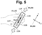
- Fig. 5 is a right-side view showing a placement example of the conventional actuators.
- Fig. 4 shows an example where the first and second actuators A1, A2 are mounted in a direction in which the first and second axes O1, 02 are parallel to all of the right-side surface 11R, the left-side surface 11L, the upper surface 11T, and the lower surface 11B, that is, the virtual plane XY, the virtual plane XZ (ZX), and the virtual plane YZ, and are perpendicular to the front surface 11F and the rear surface 11H.
- each of the vibration V1, V2 of the first and second actuators A1, A2 is in the direction Y, and hence a traction illusion is generated only in the direction Y. Therefore, in a state where the user holds the electronic equipment 1 with both hands in front of both arms, an illusion that the electronic equipment 1 is pulled obliquely to the direction Y, an illusion that the electronic equipment 1 is pulled backward, or an illusion that the electronic equipment 1 is pulled forward cannot be generated. Hence it is not possible to make the user feel a richer traction illusion or to enhance expressive power in an application, such as a game, performed by the electronic equipment 1.
- the first actuator A1 for generating the vibration V1 along the first axis O1 is mounted inside the housing 10 of the electronic equipment 1, and the first actuator A1 is mounted in a direction in which the first axis O1 is non-parallel and non-perpendicular to at least one of the six surfaces.
- the second actuator A2 for generating the vibration V2 along the second axis 02 is mounted inside the housing 10 of the electronic equipment 1, and the second actuator A2 is mounted in a direction in which the second axis 02 is non-parallel and non-perpendicular to at least one of the six surfaces.
- the first and second actuators A1, A2 may be disposed near the left-side surface 11L and the right-side surface 11R of the six surfaces, respectively. This makes it possible to effectively generate a traction illusion at a position close to a portion of the electronic equipment 1 which is held by the user.
- the first and second actuators A1, A2 may be mounted in a direction in which the first and second axes O1, 02 are each non-parallel and non-perpendicular to a common one of the six surfaces. This can enhance the intensity of the traction illusion to be generated.
- the first and second actuators A1, A2 may be mounted in a direction in which the first and second axes O1, O2 have opposite inclinations to each other by an equal angle across the common surface. Thereby, traction illusions can be efficiently generated in more directions.
- the first and second actuators A1, A2 may be mounted in a direction in which the first and second axes O1, O2 are each non-parallel and non-perpendicular to at least the left-side surface 11L or the right-side surface 11R of the six surfaces. This makes it possible to generate a traction illusion in a direction oblique to the directions X and Y, that is, the virtual planes YZ and XZ.
- the first and second actuators A1, A2 may be mounted in a direction in which the first and second axes O1, O2 are non-parallel to each other, and the first and second actuators A1, A2 may be driven by the control circuit 6 with different vibration intensities from each other. It is thereby possible to generate a traction illusion with respect to an angular direction intermediate between the first and second axes O1, O2. Adjusting the vibration intensities of the first and second actuators A1, A2 with time enables a gradual change in the direction of the traction illusion. Hence it is possible to make the user feel an extremely rich traction illusion and to greatly enhance expressive power in an application, such as a game, performed by electronic equipment 1.
- Fig. 6 is a three-side view showing the configuration of the electronic equipment according to the second embodiment.
- Fig. 7 is a right-side view showing a placement example of actuators according to the second embodiment.
- Fig. 8 is a right-side view showing an example of generation of a traction illusion in the electronic equipment according to the second embodiment.
- the first actuator A1 is mounted at a position near the left-side surface 11L of the six surfaces in a direction in which the first axis O1 is non-parallel and non-perpendicular to the lower surface 11B, that is, the virtual plane XY, and the first actuator A1 generates vibration V1 along the first axis O1. Since the lower surface 11B is parallel to the upper surface 11T and orthogonal to the front surface 11F and the rear surface 11H along the direction Z, the first axis O1 is non-parallel and non-perpendicular to the virtual plane XZ, in addition to the virtual plane XY, but is parallel to the virtual plane YZ.
- the second actuator A2 is mounted at a position near the right-side surface 11R of the six surfaces in a direction in which the second axis 02 is non-parallel and non-perpendicular to the lower surface 11B, that is, the virtual plane XY, and the second actuator A2 generates vibration V2 along the second axis 02. Since the lower surface 11B is parallel to the upper surface 11T and orthogonal to the front surface 11F and the rear surface 11H along the direction Z, the second axis 02 is non-parallel and non-perpendicular to the virtual plane XZ, in addition to the virtual plane XY, but is parallel to the virtual plane YZ.
- the first axis O1 obliquely intersects the lower surface 11B, that is, the virtual plane XY at an angle ⁇ 1 at a point P1
- the second axis 02 obliquely intersects the lower surface 11B, that is, the virtual plane XY at an angle ⁇ 2 at a point P2.
- the values of the angle ⁇ 1 and the angle ⁇ 2 are equal.
- the first and second actuators A1, A2 are mounted in a direction in which the first and second axes O1, O2 are each non-parallel and non-perpendicular to a common one of the six surfaces, that is, the lower surface 11B (upper surface 11T), in other words, the virtual plane XY.
- Fig. 9 is a right-side view showing another placement example of the actuators according to the second embodiment.
- Fig. 10 is a right-side view showing another example of generation of a traction illusion in the electronic equipment according to the second embodiment.
- Fig. 7 described above the case has been described as an example where the first and second actuators A1, A2 are mounted obliquely to the virtual plane XY so that the end of the front surface 11F is close to the lower surface 11B, but the present invention is not limited to this.
- the first and second actuators A1, A2 may be mounted obliquely to the virtual plane XY so that the end of the front surface 11F is close to the upper surface 11T.
- the first and second actuators A1, A2 are mounted in a direction in which the first and second axes O1, O2 are each non-parallel and non-perpendicular to the lower surface 11B or the upper surface 11T. This makes it possible to generate a traction illusion in a direction oblique to the virtual plane XY made up of the directions X and Y.
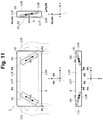
- Fig. 11 is a three-side view showing the configuration of the electronic equipment according to the third embodiment.
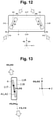
- Fig. 12 is a top view showing a placement example of actuators according to the third embodiment.
- Fig. 13 is a right-side view showing a placement example of the actuators according to the third embodiment.
- Fig. 14 is a rear view showing a placement example of the actuators according to the third embodiment.
- the first actuator A1 is mounted at a position near the left-side surface 11L of the six surfaces in a direction in which the first axis O1 is non-parallel and non-perpendicular to both the left-side surface 11L, that is, the virtual plane YZ and the lower surface 11B, that is, the virtual plane XY.
- the first actuator A1 generates vibration V1 along the first axis O1.
- the left-side surface 11L is parallel to the right-side surface 11R
- the lower surface 11B is parallel to the upper surface 11T
- the left-side surface 11L and the lower surface 11B are each orthogonal to the front surface 11F and the rear surface 11H, so that the first axis O1 is non-parallel and non-perpendicular to the virtual plane XZ in addition to the virtual plane YZ and the virtual plane XY.
- the second actuator A2 is mounted at a position near the right-side surface 11R of the six surfaces in a direction in which the second axis 02 is non-parallel and non-perpendicular to both the right-side surface 11R, that is, the virtual plane YZ, and the lower surface 11B, that is, the virtual plane XY. Thereby, the second actuator A2 generates vibration V2 along the second axis 02.
- the left-side surface 11L is parallel to the right-side surface 11R
- the lower surface 11B is parallel to the upper surface 11T
- the left-side surface 11L and the lower surface 11B are orthogonal to the front surface 11F and the rear surface 11H, so that the second axis 02 is non-parallel and non-perpendicular to the virtual plane XZ in addition to the virtual plane YZ and the virtual plane XY.
- the first and second actuators A1, A2 are mounted in a direction in which the first and second axes O1, O2 are each non-parallel and non-perpendicular to both the left-side surface 11L (right-side surface 11R) and the upper surface 11T (lower surface 11B) of the six surfaces, that is, the virtual plane YZ and the virtual plane XY.
- the first axis O1 obliquely intersects the left-side surface 11L, that is, the virtual plane YZ at an angle ⁇ 1 at a point P1 in the top view
- the second axis 02 obliquely intersects the right-side surface 11R, that is, the virtual plane YZ at an angle ⁇ 2 at a point P2 in the top view.
- the values of the angle ⁇ 1 and the angle ⁇ 2 are equal.
- the first axis O1 obliquely intersects the lower surface 11B, that is, the virtual plane XY at an angle ⁇ 3 at a point P3 in the side view
- the second axis O2 obliquely intersects the lower surface 11B, that is, the virtual plane XY at an angle ⁇ 4 at a point P4 in the side view.
- the values of the angle ⁇ 3 and the angle ⁇ 4 are equal.
- the first axis O1 obliquely intersects the lower surface 11B, that is, the virtual plane XY at an angle ⁇ 5 at a point P5 in the rear view
- the second axis 02 obliquely intersects the lower surface 11B, that is, the virtual plane XY at an angle ⁇ 6 at a point P6 in the rear view.
- the values of the angle ⁇ 5 and the angle ⁇ 6 are equal.
- the first and second actuators A1, A2 are mounted in a direction in which the first and second axes O1, O2 are each non-parallel and non-perpendicular to both the left-side surface 11L or the right-side surface 11R and the lower surface 11B or the upper surface 11T.
- This makes it possible to generate a traction illusion in a direction oblique to all of the directions X Y, and Z, that is, the virtual planes XY, YZ, and XZ.
- the housing 10 has the substantially rectangular parallelepiped shape of the flat plate with the six surfaces of the upper surface 11T, the lower surface 11B, the front surface 11F, the rear surface 11H, the left-side surface 11L, and the right-side surface 11R, and the directions of the first and second axes O1, O2 of the first actuators A1, A2 are defined by the positional relationship with these six surfaces.
- the present invention is not limited to this, and the directions of the first and second axes O1, O2 may be defined by the positional relationships with the orthogonal three axes defined for the electronic equipment 1, that is, the directions along the respective axes of the three-dimensional local coordinate system.
- a method for efficiently calculating coordinates has been adopted by defining a three-dimensional local coordinate system unique to each object existing in the space independently of the world coordinate system or the global coordinate system of the entire space.
- the three-dimensional local coordinate system is defined based on the shape and posture of each object.
- the three-dimensional local coordinate system may be defined for the electronic equipment 1, and directions along the respective axes of the three-dimensional local coordinate system may be assigned to the directions X Y, and Z described above.
- virtual planes parallel to each of the six surfaces constituting the housing 10, that is, the upper surface 11T and the lower surface 11B, the front surface 11F and the rear surface 11H, the left-side surface 11L, and the right-side surface 11R may be defined as the virtual plane XY, the virtual plane XZ, and the virtual plane YZ, and the perpendicular directions of these virtual plane XY, the virtual plane XZ, and the virtual plane YZ may be defined as the directions X Y, and Z.
- the three-dimensional local coordinate system can be defined based on the reference plane and the reference direction.
- the plane of the electronic equipment 1 can be defined as the reference plane.
- a flat member such as an LCD display or an operation panel is disposed in the electronic equipment 1
- the plane of the flat member can be defined as the reference plane.
- a direction in which both ends of the electronic equipment 1, which are held by the user with both hands, face each other can be defined as the reference direction.
- the horizontal direction (or vertical direction) of the electronic equipment 1 may be defined as the reference direction.
- the reference plane may be defined as the virtual plane XY
- the reference direction may be defined as the direction X on the virtual plane XY.
- a direction orthogonal to the direction X can be defined as the direction Y
- a perpendicular direction to the virtual plane XY can be defined as the direction Z.
- the positional relationship between the first and second axes O1, O2 of the first actuators A1, A2 and the six surfaces can be rephrased as a positional relationship with the directions along the respective axes of the three-dimensional local coordinate system defined for the electronic equipment 1.
- the positional relationship in which the first axis O1 is non-parallel to the left-side surface 11L, that is, the virtual plane YZ can be rephrased as a relationship in which the first axis O1 is non-orthogonal to the direction X.
- the positional relationship in which the first axis O1 is non-parallel to the lower surface 11B, that is, the virtual plane XY can be rephrased as a relationship in which the first axis O1 is non-orthogonal to the direction Z.
Landscapes
- Engineering & Computer Science (AREA)
- General Engineering & Computer Science (AREA)
- Multimedia (AREA)
- Theoretical Computer Science (AREA)
- Human Computer Interaction (AREA)
- Physics & Mathematics (AREA)
- General Physics & Mathematics (AREA)
- User Interface Of Digital Computer (AREA)
- Apparatuses For Generation Of Mechanical Vibrations (AREA)
Abstract
Description
- The present invention relates to a traction illusion generating technique in electronic equipment, which generates a traction illusion by vibration of an actuator.
- Conventionally, a so-called haptic device has been proposed as a pseudo-haptic touch generator that causes a person to sense a pseudo-haptic touch by asymmetric vibration of an actuator (oscillator) (e.g., see Patent Literature 1). This type of haptic device is a device using human illusions and can produce a traction illusion that a hand is being pulled in a particular direction even though the hand is not physically being pulled.
- Patent Literature 1:
Japanese domestic republication of PCT international application No. 2017-115729 - Such a haptic device has been considered to be mounted on small portable electronic equipment having a flat rectangular parallelepiped shape with a space inside, such as a smartphone, a tablet, and a portable game machine. Normally, in this type of electronic equipment, a display screen is disposed in the center of a rectangular upper surface, and when a user operates an application such as a game, it is assumed that the user holds the two short sides on the right and left-sides with the right and left hands, respectively, so that the long side of the upper surface is in the right and left direction with both arms in front.
- A general actuator used in a haptic device has a quadrangular prism shape as a whole, and it is desirable to dispose the actuator in a direction parallel or perpendicular to all six surfaces constituting a housing in consideration of the miniaturization of the housing and the placement space of the actuator. However, in many actuators, vibration is generated in the longitudinal direction, and such placement thus has a problem that only a traction illusion in a direction perpendicular to any of the six surfaces can be generated and that a traction illusion cannot be generated in an oblique direction having an inclination with these surfaces.
- The present invention is intended to solve such a problem, and an object of the present invention is to provide a traction illusion generating technique capable of generating a traction illusion in an arbitrary oblique direction.
- For achieving such an object, electronic equipment according to the present invention is provided with: a portable housing that has a substantially rectangular parallelepiped shape with six surfaces of an upper surface, a lower surface, a front surface, a rear surface, a left-side surface, and a right-side surface; a first actuator that is mounted inside the housing and configured to generate vibration along a first axis; and a control circuit configured to drive the first actuator to generate a traction illusion. The first actuator is mounted in a direction in which the first axis is non-parallel and non-perpendicular to at least one of the six surfaces.
- One configuration example of the electronic equipment according to the present invention is further provided with a second actuator that is mounted inside the housing and configured to generate vibration along a second axis. The control circuit is configured to drive the first and second actuators to generate a traction illusion, and the second actuator is mounted in a direction in which the second axis is non-parallel and non-perpendicular to at least one of the six surfaces.
- In one configuration example of the electronic equipment according to the present invention, the first and second actuators are disposed near the left-side surface and the right-side surface of the six surfaces, respectively.
- In one configuration example of the electronic equipment according to the present invention, the first and second actuators are mounted in a direction in which the first and second axes are each non-parallel and non-perpendicular to a common one of the six surfaces.
- In one configuration example of the electronic equipment according to the present invention, the first and second actuators are mounted in a direction in which the first and second axes have opposite inclinations to each other by an equal angle across the common surface.
- In one configuration example of the electronic equipment according to the present invention, the first and second actuators are mounted in a direction in which the first and second axes are each non-parallel and non-perpendicular to at least the left-side surface or the right-side surface of the six surfaces.
- In one configuration example of the electronic equipment according to the present invention, the first and second actuators are mounted in a direction in which the first and second axes are each non-parallel and non-perpendicular to at least the upper surface or the lower surface of the six surfaces.
- In one configuration example of the electronic equipment according to the present invention, the first and second actuators are mounted in a direction in which the first and second axes are each non-parallel and non-perpendicular to both of at least the left-side surface or the right-side surface and at least the upper surface or the lower surface of the six surfaces.
- In one configuration example of the electronic equipment according to the present invention, the first and second actuators are mounted in a direction in which the first and second axes are non-parallel to each other, and the first and second actuators are driven by the control circuit with different vibration intensities from each other.
- Another electronic equipment according to the present invention is provided with: a portable housing having a space inside; a first actuator that is mounted inside the housing and configured to generate vibration along a first axis; and a control circuit configured to drive the first actuator to generate a traction illusion. The first actuator is mounted in a direction in which the first axis is non-perpendicular to a direction along at least one axis of a three-dimensional local coordinate system defined in advance for the housing.
- According to the present invention, it is possible to generate a traction illusion in an arbitrary oblique direction in the housing of the electronic equipment. Hence it is possible to make the user feel a richer traction illusion and to enhance expressive power in an application, such as a game, performed by the electronic equipment.
-
- [
Fig. 1] Fig. 1 is a three-side view showing a configuration of electronic equipment according to a first embodiment. - [
Fig. 2] Fig. 2 is a block diagram showing a circuit configuration of the electronic equipment. - [
Fig. 3] Fig. 3 is a top view showing a placement example of actuators according to the first embodiment. - [
Fig. 4] Fig. 4 is a three-side view showing a placement example of conventional actuators. - [
Fig. 5] Fig. 5 is a right-side view showing a placement example of the conventional actuators. - [
Fig. 6] Fig. 6 is a three-side view showing a configuration of electronic equipment according to a second embodiment. - [
Fig. 7] Fig. 7 is a right-side view showing a placement example of actuators according to the second embodiment. - [
Fig. 8] Fig. 8 is a right-side view showing an example of generation of a traction illusion in the electronic equipment according to the second embodiment. - [
Fig. 9] Fig. 9 is a right-side view showing another placement example of the actuators according to the second embodiment. - [
Fig. 10] Fig. 10 is a right-side view showing another example of generation of a traction illusion in the electronic equipment according to the second embodiment. - [
Fig. 11] Fig. 11 is a three-side view showing a configuration of electronic equipment according to a third embodiment. - [
Fig. 12] Fig. 12 is a top view showing a placement example of actuators according to the third embodiment. - [
Fig. 13] Fig. 13 is a right-side view showing a placement example of the actuators according to the third embodiment. - [
Fig. 14] Fig. 14 is a rear view showing a placement example of the actuators according to the third embodiment. - Next, embodiments of the present invention will be described with reference to the drawings.
- First,
electronic equipment 1 according to a first embodiment of the present invention will be described with reference toFigs. 1 ,2 , and3 .Fig. 1 is a three-side view showing a configuration of the electronic equipment according to the first embodiment.Fig. 2 is a block diagram showing a circuit configuration of the electronic equipment.Fig. 3 is a top view showing a placement example of actuators according to the first embodiment. - Like a smartphone, a tablet, and a portable game machine, the
electronic equipment 1 according to the present invention has a smallportable housing 10 having a substantially rectangular parallelepiped shape of a flat plate with six surfaces of anupper surface 11T, alower surface 11B, afront surface 11F, arear surface 11H, a left-side surface 11L, and a right-side surface 11R. - In the following description, directions along the X, Y, and Z axes orthogonal to each other will be referred to as the directions X Y, and Z, respectively. Further, of the six surfaces constituting the
housing 10, the left-side surface 11L and the right-side surface 11R are assumed to face each other in parallel along the direction X, thefront surface 11F and therear surface 11H are assumed to face each other in parallel along the direction Y, and theupper surface 11T and thelower surface 11B are assumed to face each other in parallel along the direction Z. Virtual planes parallel to theupper surface 11T andlower surface 11B, thefront surface 11F andrear surface 11H, and the left-side surface 11L and the right-side surface 11R are referred to as a virtual plane XY, a virtual plane XZ (ZX), and a virtual plane YZ. - As shown in
Fig. 2 , theelectronic equipment 1 is mounted with, as main circuit components, a communication interface (I/F)circuit 2, anoperation input circuit 3, adisplay circuit 4, astorage circuit 5, acontrol circuit 6, a first actuator A1, and a second actuator A2, and these circuit units are mounted in a space inside thehousing 10. - The communication I/
F circuit 2 is a circuit unit that performs data communication with an external apparatus (not shown) via a wireless line or a wired line. - The
operation input circuit 3 includes an operation input apparatus, such as a touch key, an operation button, and an operation switch, and is a circuit unit for detecting a user's operation and outputting the operation to thecontrol circuit 6. - The
display circuit 4 includes a display apparatus, such as a liquid crystal display (LCD) or a light-emitting diode (LED), and is a circuit unit for visually displaying the display content output from thecontrol circuit 6. In the following description, thedisplay circuit 4 is shown in each drawing for ease of understanding, but the present invention is not limited to this, and thedisplay circuit 4 may not be provided. - The
storage circuit 5 includes a storage apparatus, such as a semiconductor memory, and is a circuit unit for storing processing data and a program used for various processing to be executed by thecontrol circuit 6. - The
control circuit 6 has a central processing unit (CPU) and its peripheral circuits and has a function of executing various processing, such as various applications and control for generating a traction illusion, by cooperating the CPU with the program of thestorage circuit 5. - A first actuator (oscillator) A1 is a circuit unit that generates vibration V1 along a first axis O1.
- A second actuator (oscillator) A2 is a circuit unit that generates vibration V2 along a
second axis 02. - As specific examples of the first and second actuators A1, A2, for example, an oscillator having a known configuration as described in above-mentioned
Patent Literature 1 may be used. - In the present invention, the first actuator A1 is mounted in a direction in which the first axis O1 is non-parallel and non-perpendicular to at least one of the six surfaces, and the second actuator A2 is mounted in a direction in which the
second axis 02 is non-parallel and non-perpendicular to at least one of the six surfaces. - For ease of understanding, in the following description, a case where the
electronic equipment 1 includes both the first actuator A1 and the second actuator A2 will be described as an example, but the present invention is not limited to this. For example, even when only one actuator, such as only the first actuator A1, is mounted, similar effects to those described below can be obtained. - As shown in
Fig. 1 , in the present embodiment, the first actuator A1 is mounted at a position near the left-side surface 11L of the six surfaces in a direction in which the first axis O1 is non-parallel and non-perpendicular to the left-side surface 11L, that is, the virtual plane YZ, and the first actuator A1 generates vibration V1 along the first axis O1. Since the left-side surface 11L is parallel to the right-side surface 11R and orthogonal to thefront surface 11F and therear surface 11H along the direction Z, the first axis O1 is non-parallel and non-perpendicular to the virtual plane XZ, in addition to the virtual plane YZ, but is parallel to the virtual plane XY. - Further, in the present embodiment, the second actuator A2 is mounted at a position near the right-
side surface 11R of the six surfaces in a direction in which thesecond axis 02 is non-parallel and non-perpendicular to the right-side surface 11R, that is, the virtual plane YZ, and the second actuator A2 generates vibration V2 along thesecond axis 02. Since the right-side surface 11R is parallel to the left-side surface 11L and orthogonal to thefront surface 11F and therear surface 11H along the direction Z, thesecond axis 02 is non-parallel and non-perpendicular to the virtual plane XZ, in addition to the virtual plane YZ, but is parallel to the virtual plane XY. - Thus, in the present embodiment, the first and second actuators A1, A2 are mounted in a direction in which the first and second axes O1, 02 are each non-parallel and non-perpendicular to a common one of the six surfaces, that is, the left-
side surface 11L (right-side surface 11R), in other words, the same virtual plane YZ. - Specifically, as shown in
Fig. 3 , the first axis O1 obliquely intersects the left-side surface 11L, that is, the virtual plane YZ at an angle θ1 at a point P1, and thesecond axis 02 obliquely intersects the right-side surface 11R, that is, the virtual plane YZ at an angle θ2 at a point P2. In the present embodiment, the values of the angle θ1 and the angle θ2 are equal. Thus, the first and second actuators A1, A2 are disposed in a direction in which the first and second axes O1, 02 have opposite inclinations to each other by an equal angle θ1 (= θ2) with respect to the right-side surface 11R or the left-side surface 11L, that is, the virtual plane YZ, in other words, the first and second actuators A1, A2 are disposed in a shape of the Chinese character for eight as seen from therear surface 11H. In this case, the first and second actuators A1, A2 may be disposed in an inverted shape of the Chinese character for eight as seen from therear surface 11H. - Therefore, in the traction illusion generation control of the
control circuit 6, the vibration V1 along the first axis O1 is generated only by driving the first actuator A1, so that the traction illusion can be generated in a direction oblique to the right-side surface 11R and the left-side surface 11L, that is, the virtual plane YZ. Further, the vibration V2 along thesecond axis 02 is generated only by driving the second actuator A2, so that the traction illusion can be generated in the direction oblique to the right-side surface 11R and the left-side surface 11L, that is, the virtual plane YZ. - Moreover, by unbalancing the intensities of the vibration V1, V2 of the first and second actuators A1, A2, a traction illusion can be generated with respect to an angular direction intermediate between the first axis O1 and the
second axis 02, for example. Therefore, adjusting the intensity balance of the vibration V1, V2 with time enables a gradual change in the direction of the traction illusion. In addition, when the first and second actuators A1, A2 are simultaneously driven with the same intensity, a traction illusion along the direction Y can be generated in the same manner as in the conventional case. -
Fig. 4 is a three-side view showing a placement example of conventional actuators.Fig. 5 is a right-side view showing a placement example of the conventional actuators.Fig. 4 shows an example where the first and second actuators A1, A2 are mounted in a direction in which the first and second axes O1, 02 are parallel to all of the right-side surface 11R, the left-side surface 11L, theupper surface 11T, and thelower surface 11B, that is, the virtual plane XY, the virtual plane XZ (ZX), and the virtual plane YZ, and are perpendicular to thefront surface 11F and therear surface 11H. - With the mounting in such a direction, as shown in
Fig. 5 , each of the vibration V1, V2 of the first and second actuators A1, A2 is in the direction Y, and hence a traction illusion is generated only in the direction Y. Therefore, in a state where the user holds theelectronic equipment 1 with both hands in front of both arms, an illusion that theelectronic equipment 1 is pulled obliquely to the direction Y, an illusion that theelectronic equipment 1 is pulled backward, or an illusion that theelectronic equipment 1 is pulled forward cannot be generated. Hence it is not possible to make the user feel a richer traction illusion or to enhance expressive power in an application, such as a game, performed by theelectronic equipment 1. - As described above, in the present embodiment, the first actuator A1 for generating the vibration V1 along the first axis O1 is mounted inside the
housing 10 of theelectronic equipment 1, and the first actuator A1 is mounted in a direction in which the first axis O1 is non-parallel and non-perpendicular to at least one of the six surfaces. Further, in the present embodiment, the second actuator A2 for generating the vibration V2 along thesecond axis 02 is mounted inside thehousing 10 of theelectronic equipment 1, and the second actuator A2 is mounted in a direction in which thesecond axis 02 is non-parallel and non-perpendicular to at least one of the six surfaces. - This makes it possible to generate a traction illusion not in a direction horizontal or vertical to the six surfaces of the
housing 10 but in a direction oblique to any of the six surfaces. Hence it is possible to make the user feel a richer traction illusion and to enhance expressive power in an application, such as a game, performed by theelectronic equipment 1. - In the present embodiment, the first and second actuators A1, A2 may be disposed near the left-
side surface 11L and the right-side surface 11R of the six surfaces, respectively. This makes it possible to effectively generate a traction illusion at a position close to a portion of theelectronic equipment 1 which is held by the user. - In the present embodiment, the first and second actuators A1, A2 may be mounted in a direction in which the first and second axes O1, 02 are each non-parallel and non-perpendicular to a common one of the six surfaces. This can enhance the intensity of the traction illusion to be generated.
- In the present embodiment, the first and second actuators A1, A2 may be mounted in a direction in which the first and second axes O1, O2 have opposite inclinations to each other by an equal angle across the common surface. Thereby, traction illusions can be efficiently generated in more directions.
- Further, in the present embodiment, the first and second actuators A1, A2 may be mounted in a direction in which the first and second axes O1, O2 are each non-parallel and non-perpendicular to at least the left-
side surface 11L or the right-side surface 11R of the six surfaces. This makes it possible to generate a traction illusion in a direction oblique to the directions X and Y, that is, the virtual planes YZ and XZ. - In the present embodiment, the first and second actuators A1, A2 may be mounted in a direction in which the first and second axes O1, O2 are non-parallel to each other, and the first and second actuators A1, A2 may be driven by the
control circuit 6 with different vibration intensities from each other. It is thereby possible to generate a traction illusion with respect to an angular direction intermediate between the first and second axes O1, O2. Adjusting the vibration intensities of the first and second actuators A1, A2 with time enables a gradual change in the direction of the traction illusion. Hence it is possible to make the user feel an extremely rich traction illusion and to greatly enhance expressive power in an application, such as a game, performed byelectronic equipment 1. - Next,
electronic equipment 1 according to a second embodiment of the present invention will be described with reference toFigs. 6 ,7 , and8 .Fig. 6 is a three-side view showing the configuration of the electronic equipment according to the second embodiment.Fig. 7 is a right-side view showing a placement example of actuators according to the second embodiment.Fig. 8 is a right-side view showing an example of generation of a traction illusion in the electronic equipment according to the second embodiment. - As shown in
Figs. 6 and7 , in the present embodiment, the first actuator A1 is mounted at a position near the left-side surface 11L of the six surfaces in a direction in which the first axis O1 is non-parallel and non-perpendicular to thelower surface 11B, that is, the virtual plane XY, and the first actuator A1 generates vibration V1 along the first axis O1. Since thelower surface 11B is parallel to theupper surface 11T and orthogonal to thefront surface 11F and therear surface 11H along the direction Z, the first axis O1 is non-parallel and non-perpendicular to the virtual plane XZ, in addition to the virtual plane XY, but is parallel to the virtual plane YZ. - Further, in the present embodiment, the second actuator A2 is mounted at a position near the right-
side surface 11R of the six surfaces in a direction in which thesecond axis 02 is non-parallel and non-perpendicular to thelower surface 11B, that is, the virtual plane XY, and the second actuator A2 generates vibration V2 along thesecond axis 02. Since thelower surface 11B is parallel to theupper surface 11T and orthogonal to thefront surface 11F and therear surface 11H along the direction Z, thesecond axis 02 is non-parallel and non-perpendicular to the virtual plane XZ, in addition to the virtual plane XY, but is parallel to the virtual plane YZ. - Specifically, as shown in
Fig. 7 , the first axis O1 obliquely intersects thelower surface 11B, that is, the virtual plane XY at an angle θ1 at a point P1, and thesecond axis 02 obliquely intersects thelower surface 11B, that is, the virtual plane XY at an angle θ2 at a point P2. In the present embodiment, the values of the angle θ1 and the angle θ2 are equal. Hence the first and second actuators A1, A2 are disposed parallel to each other in a direction in which the first and second axes O1, 02 are inclined by an equal angle θ1 (= θ2) with respect to thelower surface 11B or theupper surface 11T, that is, the virtual plane XY. - Thus, in the present embodiment, the first and second actuators A1, A2 are mounted in a direction in which the first and second axes O1, O2 are each non-parallel and non-perpendicular to a common one of the six surfaces, that is, the
lower surface 11B (upper surface 11T), in other words, the virtual plane XY. - Therefore, as shown in
Fig. 8 , in a state where the user holds theelectronic equipment 1 with both hands in front of both arms, it is possible to generate an illusion that theelectronic equipment 1 is pulled backward and an illusion that theelectronic equipment 1 is pulled forward, not in the direction along the virtual plane XY. -
Fig. 9 is a right-side view showing another placement example of the actuators according to the second embodiment.Fig. 10 is a right-side view showing another example of generation of a traction illusion in the electronic equipment according to the second embodiment. InFig. 7 described above, the case has been described as an example where the first and second actuators A1, A2 are mounted obliquely to the virtual plane XY so that the end of thefront surface 11F is close to thelower surface 11B, but the present invention is not limited to this. - In the present embodiment, as shown in
Fig. 9 , the first and second actuators A1, A2 may be mounted obliquely to the virtual plane XY so that the end of thefront surface 11F is close to theupper surface 11T. - Thus, as shown in
Fig. 10 , in a state where the user holds theelectronic equipment 1 with both hands in front of both arms, it is possible to generate an illusion that theelectronic equipment 1 is pulled upward or downward, not in the direction along the virtual plane XY. - As described above, in the present embodiment, the first and second actuators A1, A2 are mounted in a direction in which the first and second axes O1, O2 are each non-parallel and non-perpendicular to the
lower surface 11B or theupper surface 11T. This makes it possible to generate a traction illusion in a direction oblique to the virtual plane XY made up of the directions X and Y. - Therefore, in a state where the user holds the
electronic equipment 1 with both hands in front of both arms, it is possible to generate illusions that theelectronic equipment 1 is pulled in various directions as described below in addition to the direction along the virtual plane XY as shown inFig. 5 . Specifically, such illusions are an illusion that theelectronic equipment 1 is pulled in a direction oblique to the virtual plane XY, that is, backward or forward as shown inFig. 8 , and an illusion that theelectronic equipment 1 is pulled upward or downward. Hence it is possible to make the user feel a richer traction illusion and to enhance expressive power in an application, such as a game, performed by theelectronic equipment 1. - Next,
electronic equipment 1 according to a third embodiment of the present invention will be described with reference toFigs. 11 ,12 ,13 , and14 .Fig. 11 is a three-side view showing the configuration of the electronic equipment according to the third embodiment.Fig. 12 is a top view showing a placement example of actuators according to the third embodiment.Fig. 13 is a right-side view showing a placement example of the actuators according to the third embodiment.Fig. 14 is a rear view showing a placement example of the actuators according to the third embodiment. - As shown in
Fig. 11 , in the present embodiment, the first actuator A1 is mounted at a position near the left-side surface 11L of the six surfaces in a direction in which the first axis O1 is non-parallel and non-perpendicular to both the left-side surface 11L, that is, the virtual plane YZ and thelower surface 11B, that is, the virtual plane XY. Thus, the first actuator A1 generates vibration V1 along the first axis O1. The left-side surface 11L is parallel to the right-side surface 11R, thelower surface 11B is parallel to theupper surface 11T, and the left-side surface 11L and thelower surface 11B are each orthogonal to thefront surface 11F and therear surface 11H, so that the first axis O1 is non-parallel and non-perpendicular to the virtual plane XZ in addition to the virtual plane YZ and the virtual plane XY. - Further, in the present embodiment, the second actuator A2 is mounted at a position near the right-
side surface 11R of the six surfaces in a direction in which thesecond axis 02 is non-parallel and non-perpendicular to both the right-side surface 11R, that is, the virtual plane YZ, and thelower surface 11B, that is, the virtual plane XY. Thereby, the second actuator A2 generates vibration V2 along thesecond axis 02. The left-side surface 11L is parallel to the right-side surface 11R, thelower surface 11B is parallel to theupper surface 11T, and the left-side surface 11L and thelower surface 11B are orthogonal to thefront surface 11F and therear surface 11H, so that thesecond axis 02 is non-parallel and non-perpendicular to the virtual plane XZ in addition to the virtual plane YZ and the virtual plane XY. - Thus, in the present embodiment, the first and second actuators A1, A2 are mounted in a direction in which the first and second axes O1, O2 are each non-parallel and non-perpendicular to both the left-
side surface 11L (right-side surface 11R) and theupper surface 11T (lower surface 11B) of the six surfaces, that is, the virtual plane YZ and the virtual plane XY. - Specifically, as shown in
Fig. 12 , the first axis O1 obliquely intersects the left-side surface 11L, that is, the virtual plane YZ at an angle θ1 at a point P1 in the top view, and thesecond axis 02 obliquely intersects the right-side surface 11R, that is, the virtual plane YZ at an angle θ2 at a point P2 in the top view. In the present embodiment, the values of the angle θ1 and the angle θ2 are equal. Thus, the first and second actuators A1, A2 are disposed in a direction in which the first and second axes O1, O2 have opposite inclinations to each other by an equal angle θ1 (= θ2) in the top view with respect to the right-side surface 11R or the left-side surface 11L, that is, the virtual plane YZ, in other words, the first and second actuators A1, A2 are disposed in a shape of the Chinese character for eight as seen from therear surface 11H. - Further, as shown in
Fig. 13 , the first axis O1 obliquely intersects thelower surface 11B, that is, the virtual plane XY at an angle θ3 at a point P3 in the side view, and the second axis O2 obliquely intersects thelower surface 11B, that is, the virtual plane XY at an angle θ4 at a point P4 in the side view. In the present embodiment, the values of the angle θ3 and the angle θ4 are equal. Hence the first and second actuators A1, A2 are disposed in a direction in which the first and second axes O1, 02 are inclined by an equal angle θ3 (= θ4), in the side view, with respect to thelower surface 11B or theupper surface 11T, that is, the virtual plane XY. - Further, as shown in
Fig. 14 , the first axis O1 obliquely intersects thelower surface 11B, that is, the virtual plane XY at an angle θ5 at a point P5 in the rear view, and thesecond axis 02 obliquely intersects thelower surface 11B, that is, the virtual plane XY at an angle θ6 at a point P6 in the rear view. In the present embodiment, the values of the angle θ5 and the angle θ6 are equal. Hence the first and second actuators A1, A2 are disposed in a direction in which the first and second axes O1, O2 are inclined by an equal angle θ5 (= θ6), in the rear view, with respect to thelower surface 11B or theupper surface 11T, that is, the virtual plane XY. - As described above, in the present embodiment, the first and second actuators A1, A2 are mounted in a direction in which the first and second axes O1, O2 are each non-parallel and non-perpendicular to both the left-
side surface 11L or the right-side surface 11R and thelower surface 11B or theupper surface 11T. This makes it possible to generate a traction illusion in a direction oblique to all of the directions X Y, and Z, that is, the virtual planes XY, YZ, and XZ. - Therefore, in a state where the user holds the
electronic equipment 1 with both hands in front of both arms, it is possible to generate an illusion that theelectronic equipment 1 is pulled not only in the direction along the virtual plane XY as shown inFig. 5 described above, but also in a direction oblique to each of all the virtual planes XY, YZ, and XZ. Hence it is possible to make the user feel a richer traction illusion and to enhance expressive power in an application, such as a game, performed by theelectronic equipment 1. - Although the present invention has been described with reference to the above embodiments, the present invention is not limited to the above embodiments. Various modifications can be made to the configuration and details of the present invention as can be understood by those skilled in the art within the scope of the present invention. In addition, each embodiment can be implemented in any combination within a range that is not inconsistent.
- In each of the embodiments described above, the case has been described as an example where the
housing 10 has the substantially rectangular parallelepiped shape of the flat plate with the six surfaces of theupper surface 11T, thelower surface 11B, thefront surface 11F, therear surface 11H, the left-side surface 11L, and the right-side surface 11R, and the directions of the first and second axes O1, O2 of the first actuators A1, A2 are defined by the positional relationship with these six surfaces. However, the present invention is not limited to this, and the directions of the first and second axes O1, O2 may be defined by the positional relationships with the orthogonal three axes defined for theelectronic equipment 1, that is, the directions along the respective axes of the three-dimensional local coordinate system. - In general, in a case where coordinates are calculated in a three-dimensional space, a method for efficiently calculating coordinates has been adopted by defining a three-dimensional local coordinate system unique to each object existing in the space independently of the world coordinate system or the global coordinate system of the entire space. The three-dimensional local coordinate system is defined based on the shape and posture of each object. Hence the three-dimensional local coordinate system may be defined for the
electronic equipment 1, and directions along the respective axes of the three-dimensional local coordinate system may be assigned to the directions X Y, and Z described above. - At this time, in a case where the three-dimensional local coordinate system for the
electronic equipment 1 is defined based on the shape, as described above, virtual planes parallel to each of the six surfaces constituting thehousing 10, that is, theupper surface 11T and thelower surface 11B, thefront surface 11F and therear surface 11H, the left-side surface 11L, and the right-side surface 11R, may be defined as the virtual plane XY, the virtual plane XZ, and the virtual plane YZ, and the perpendicular directions of these virtual plane XY, the virtual plane XZ, and the virtual plane YZ may be defined as the directions X Y, and Z. - In a case where a reference plane serving as a reference of the
electronic equipment 1 exists, when a reference direction serving as a reference on the reference plane can be defined, the three-dimensional local coordinate system can be defined based on the reference plane and the reference direction. - For example, when the
electronic equipment 1 has a flat shape like a smartphone, a pad, and a portable game machine, or when a main plane is provided in a part of theelectronic equipment 1 like a game controller, the plane of theelectronic equipment 1 can be defined as the reference plane. Alternatively, when a flat member such as an LCD display or an operation panel is disposed in theelectronic equipment 1, the plane of the flat member can be defined as the reference plane. When the user holds and uses theelectronic equipment 1 with both hands like a portable game machine and a game controller, a direction in which both ends of theelectronic equipment 1, which are held by the user with both hands, face each other can be defined as the reference direction. Alternatively, in the basic posture of theelectronic equipment 1 at the time when the user uses theelectronic equipment 1, the horizontal direction (or vertical direction) of theelectronic equipment 1 may be defined as the reference direction. - When the reference plane and the reference direction of the
electronic equipment 1 can be defined in this manner, the reference plane may be defined as the virtual plane XY, and the reference direction may be defined as the direction X on the virtual plane XY. Thereby, on the virtual plane XY, a direction orthogonal to the direction X can be defined as the direction Y, and a perpendicular direction to the virtual plane XY can be defined as the direction Z. - Therefore, the positional relationship between the first and second axes O1, O2 of the first actuators A1, A2 and the six surfaces can be rephrased as a positional relationship with the directions along the respective axes of the three-dimensional local coordinate system defined for the
electronic equipment 1. - For example, as shown in
Figs. 3 and14 , the positional relationship in which the first axis O1 is non-parallel to the left-side surface 11L, that is, the virtual plane YZ, can be rephrased as a relationship in which the first axis O1 is non-orthogonal to the direction X. As shown inFigs. 7 and 9 , the positional relationship in which the first axis O1 is non-parallel to thelower surface 11B, that is, the virtual plane XY, can be rephrased as a relationship in which the first axis O1 is non-orthogonal to the direction Z. -
- 1
- Electronic equipment
- 2
- Communication I/F circuit
- 3
- Operation input circuit
- 4
- Display circuit
- 5
- Storage circuit
- 6
- Control circuit
- A1
- First actuator
- A2
- Second actuator
- 10
- Housing
- 11T
- Upper surface
- 11B
- Lower surface
- 11F
- Front surface
- 11H
- Rear surface
- 11L
- Left-side surface
- 11R
- Right-side surface
- O1
- First axis
- 02
- Second axis
- V1, V2
- Vibration
Claims (10)
- Electronic equipment comprising:a portable housing having a substantially rectangular parallelepiped shape with six surfaces of an upper surface, a lower surface, a front surface, a rear surface, a left-side surface, and a right-side surface;a first actuator that is mounted inside the housing and configured to generate vibration along a first axis; anda control circuit configured to drive the first actuator to generate a traction illusion,wherein the first actuator is mounted in a direction in which the first axis is non-parallel and non-perpendicular to at least one of the six surfaces.
- The electronic equipment according to claim 1, further comprisinga second actuator that is mounted inside the housing and configured to generate vibration along a second axis,whereinthe control circuit is configured to drive the first and second actuators to generate a traction illusion, andthe second actuator is mounted in a direction in which the second axis is non-parallel and non-perpendicular to at least one of the six surfaces.
- The electronic equipment according to claim 2, wherein the first and second actuators are disposed near the left-side surface and the right-side surface of the six surfaces, respectively.
- The electronic equipment according to claim 2 or 3, wherein the first and second actuators are mounted in a direction in which the first and second axes are each non-parallel and non-perpendicular to a common one of the six surfaces.
- The electronic equipment according to claim 4, wherein the first and second actuators are mounted in a direction in which the first and second axes have opposite inclinations to each other by an equal angle across the common surface.
- The electronic equipment according to any one of claims 2 to 4, wherein the first and second actuators are mounted in a direction in which the first and second axes are each non-parallel and non-perpendicular to at least the left-side surface or the right-side surface of the six surfaces.
- The electronic equipment according to any one of claims 2 to 4, wherein the first and second actuators are mounted in a direction in which the first and second axes are each non-parallel and non-perpendicular to at least the upper surface or the lower surface of the six surfaces.
- The electronic equipment according to any one of claims 2 to 4, wherein the first and second actuators are mounted in a direction in which the first and second axes are each non-parallel and non-perpendicular to both of at least the left-side surface or the right-side surface and at least the upper surface or the lower surface of the six surfaces.
- The electronic equipment according to any one of claims 2 to 8, whereinthe first and second actuators are mounted in a direction in which the first and second axes are non-parallel to each other, andthe first and second actuators are driven by the control circuit with different vibration intensities from each other.
- Electronic equipment comprising:a portable housing having a space inside;a first actuator that is mounted inside the housing and configured to generate vibration along a first axis; anda control circuit configured to drive the first actuator to generate a traction illusion,wherein the first actuator is mounted in a direction in which the first axis is non-perpendicular to a direction along at least one axis of a three-dimensional local coordinate system defined in advance for the housing.
Applications Claiming Priority (2)
| Application Number | Priority Date | Filing Date | Title |
|---|---|---|---|
| JP2019057939A JP7200790B2 (en) | 2019-03-26 | 2019-03-26 | Electronics |
| PCT/JP2020/010451 WO2020195813A1 (en) | 2019-03-26 | 2020-03-11 | Electronic apparatus that generates illusion of diagonal traction |
Publications (3)
| Publication Number | Publication Date |
|---|---|
| EP3951562A1 true EP3951562A1 (en) | 2022-02-09 |
| EP3951562A4 EP3951562A4 (en) | 2022-12-28 |
| EP3951562B1 EP3951562B1 (en) | 2025-07-02 |
Family
ID=72611420
Family Applications (1)
| Application Number | Title | Priority Date | Filing Date |
|---|---|---|---|
| EP20779439.7A Active EP3951562B1 (en) | 2019-03-26 | 2020-03-11 | Electronic apparatus that generates illusion of diagonal traction |
Country Status (4)
| Country | Link |
|---|---|
| US (1) | US11797092B2 (en) |
| EP (1) | EP3951562B1 (en) |
| JP (1) | JP7200790B2 (en) |
| WO (1) | WO2020195813A1 (en) |
Families Citing this family (1)
| Publication number | Priority date | Publication date | Assignee | Title |
|---|---|---|---|---|
| JP2023172650A (en) * | 2022-05-24 | 2023-12-06 | キヤノン株式会社 | Electronics |
Family Cites Families (7)
| Publication number | Priority date | Publication date | Assignee | Title |
|---|---|---|---|---|
| JP5275025B2 (en) | 2005-06-27 | 2013-08-28 | コアクティヴ・ドライヴ・コーポレイション | Synchronous vibrator for tactile feedback |
| JP2011183374A (en) | 2010-02-10 | 2011-09-22 | Sanyo Electric Co Ltd | Electronic device |
| CN103620928A (en) * | 2011-03-17 | 2014-03-05 | 联合活跃驱动公司 | Asymmetric and general vibration waveforms from a plurality of synchronized vibration actuators |
| JP5905312B2 (en) * | 2012-03-27 | 2016-04-20 | 京セラ株式会社 | Sound equipment |
| US10864552B2 (en) | 2015-12-28 | 2020-12-15 | Nippon Telegraph And Telephone Corporation | Pseudo force sense generation apparatus |
| EP3242187B1 (en) * | 2016-05-04 | 2018-11-21 | Vestel Elektronik Sanayi ve Ticaret A.S. | System and method for simulating a reaction force from a virtual object |
| JP7071614B2 (en) * | 2017-01-27 | 2022-05-19 | ミツミ電機株式会社 | Vibration device, wearable terminal and incoming call notification function device |
-
2019
- 2019-03-26 JP JP2019057939A patent/JP7200790B2/en active Active
-
2020
- 2020-03-11 US US17/436,776 patent/US11797092B2/en active Active
- 2020-03-11 WO PCT/JP2020/010451 patent/WO2020195813A1/en not_active Ceased
- 2020-03-11 EP EP20779439.7A patent/EP3951562B1/en active Active
Also Published As
| Publication number | Publication date |
|---|---|
| JP7200790B2 (en) | 2023-01-10 |
| EP3951562A4 (en) | 2022-12-28 |
| JP2020160660A (en) | 2020-10-01 |
| EP3951562B1 (en) | 2025-07-02 |
| US20220179490A1 (en) | 2022-06-09 |
| WO2020195813A1 (en) | 2020-10-01 |
| US11797092B2 (en) | 2023-10-24 |
Similar Documents
| Publication | Publication Date | Title |
|---|---|---|
| CN109656354B (en) | Information processing apparatus, information processing method, and computer program | |
| CN112783328B (en) | Method for providing virtual space, method for providing virtual experience, program, and recording medium | |
| JP4814761B2 (en) | Display device with small display | |
| KR102675268B1 (en) | A foldable electronic device and method for operating multi-window using the same | |
| US20150029091A1 (en) | Information presentation apparatus and information processing system | |
| JP2012133068A (en) | Multi-display system, terminal, method and program | |
| JP2002281526A (en) | Image generation device, program, and information storage medium | |
| US10824203B2 (en) | Routing of flex circuit for touch panel | |
| CN102790898A (en) | Display control device, display control method, program, and recording medium | |
| KR102683807B1 (en) | Haptic feedback device and electronic device having haptic feedback function | |
| EP3951562B1 (en) | Electronic apparatus that generates illusion of diagonal traction | |
| US20140146446A1 (en) | Electronic Device | |
| JP2010205031A (en) | Method, system and program for specifying input position | |
| US20150235337A1 (en) | Multi-chassis coordinated display system | |
| JP2003103051A (en) | Transparent touch panel device for portable type video game machine | |
| JP2018032383A (en) | Method and apparatus for supporting input in virtual space, and program for causing computer to execute the method | |
| KR20180019270A (en) | Haptic device connected to AR device or VR device | |
| CN210155628U (en) | Industrial vision application platform device | |
| JP5864018B1 (en) | Computer program | |
| KR20020022695A (en) | User input device with memory | |
| JP2008140064A (en) | Information processing device | |
| CN2420676Y (en) | A computer interface card capable of changing the working power source | |
| KR20150013472A (en) | Method and apparatus for providing 3d input | |
| CN111435272B (en) | Input device and notebook computer | |
| CN116909464A (en) | AR interaction method, device, equipment and medium |
Legal Events
| Date | Code | Title | Description |
|---|---|---|---|
| STAA | Information on the status of an ep patent application or granted ep patent |
Free format text: STATUS: THE INTERNATIONAL PUBLICATION HAS BEEN MADE |
|
| PUAI | Public reference made under article 153(3) epc to a published international application that has entered the european phase |
Free format text: ORIGINAL CODE: 0009012 |
|
| STAA | Information on the status of an ep patent application or granted ep patent |
Free format text: STATUS: REQUEST FOR EXAMINATION WAS MADE |
|
| 17P | Request for examination filed |
Effective date: 20210902 |
|
| AK | Designated contracting states |
Kind code of ref document: A1 Designated state(s): AL AT BE BG CH CY CZ DE DK EE ES FI FR GB GR HR HU IE IS IT LI LT LU LV MC MK MT NL NO PL PT RO RS SE SI SK SM TR |
|
| DAV | Request for validation of the european patent (deleted) | ||
| DAX | Request for extension of the european patent (deleted) | ||
| A4 | Supplementary search report drawn up and despatched |
Effective date: 20221125 |
|
| RIC1 | Information provided on ipc code assigned before grant |
Ipc: A63F 13/285 20140101ALI20221121BHEP Ipc: G06F 3/04883 20220101ALI20221121BHEP Ipc: A63F 13/92 20140101ALI20221121BHEP Ipc: G05G 5/03 20080401ALI20221121BHEP Ipc: G05G 5/00 20060101ALI20221121BHEP Ipc: B06B 1/00 20060101ALI20221121BHEP Ipc: G06F 3/041 20060101ALI20221121BHEP Ipc: G06F 3/01 20060101AFI20221121BHEP |
|
| STAA | Information on the status of an ep patent application or granted ep patent |
Free format text: STATUS: EXAMINATION IS IN PROGRESS |
|
| 17Q | First examination report despatched |
Effective date: 20230824 |
|
| GRAP | Despatch of communication of intention to grant a patent |
Free format text: ORIGINAL CODE: EPIDOSNIGR1 |
|
| STAA | Information on the status of an ep patent application or granted ep patent |
Free format text: STATUS: GRANT OF PATENT IS INTENDED |
|
| RIC1 | Information provided on ipc code assigned before grant |
Ipc: B06B 1/12 20060101ALI20240806BHEP Ipc: A63F 13/285 20140101ALI20240806BHEP Ipc: G06F 3/04883 20220101ALI20240806BHEP Ipc: A63F 13/92 20140101ALI20240806BHEP Ipc: G05G 5/03 20080401ALI20240806BHEP Ipc: G05G 5/00 20060101ALI20240806BHEP Ipc: B06B 1/00 20060101ALI20240806BHEP Ipc: G06F 3/041 20060101ALI20240806BHEP Ipc: G06F 3/01 20060101AFI20240806BHEP |
|
| INTG | Intention to grant announced |
Effective date: 20240904 |
|
| GRAJ | Information related to disapproval of communication of intention to grant by the applicant or resumption of examination proceedings by the epo deleted |
Free format text: ORIGINAL CODE: EPIDOSDIGR1 |
|
| STAA | Information on the status of an ep patent application or granted ep patent |
Free format text: STATUS: EXAMINATION IS IN PROGRESS |
|
| GRAP | Despatch of communication of intention to grant a patent |
Free format text: ORIGINAL CODE: EPIDOSNIGR1 |
|
| STAA | Information on the status of an ep patent application or granted ep patent |
Free format text: STATUS: GRANT OF PATENT IS INTENDED |
|
| INTC | Intention to grant announced (deleted) | ||
| INTG | Intention to grant announced |
Effective date: 20250130 |
|
| GRAS | Grant fee paid |
Free format text: ORIGINAL CODE: EPIDOSNIGR3 |
|
| GRAA | (expected) grant |
Free format text: ORIGINAL CODE: 0009210 |
|
| STAA | Information on the status of an ep patent application or granted ep patent |
Free format text: STATUS: THE PATENT HAS BEEN GRANTED |
|
| AK | Designated contracting states |
Kind code of ref document: B1 Designated state(s): AL AT BE BG CH CY CZ DE DK EE ES FI FR GB GR HR HU IE IS IT LI LT LU LV MC MK MT NL NO PL PT RO RS SE SI SK SM TR |
|
| REG | Reference to a national code |
Ref country code: GB Ref legal event code: FG4D |
|
| REG | Reference to a national code |
Ref country code: CH Ref legal event code: EP |
|
| REG | Reference to a national code |
Ref country code: DE Ref legal event code: R096 Ref document number: 602020053856 Country of ref document: DE |
|
| REG | Reference to a national code |
Ref country code: IE Ref legal event code: FG4D |
|
| RAP4 | Party data changed (patent owner data changed or rights of a patent transferred) |
Owner name: NTT, INC. |
|
| REG | Reference to a national code |
Ref country code: NL Ref legal event code: MP Effective date: 20250702 |
|
| PG25 | Lapsed in a contracting state [announced via postgrant information from national office to epo] |
Ref country code: PT Free format text: LAPSE BECAUSE OF FAILURE TO SUBMIT A TRANSLATION OF THE DESCRIPTION OR TO PAY THE FEE WITHIN THE PRESCRIBED TIME-LIMIT Effective date: 20251103 |
|
| PG25 | Lapsed in a contracting state [announced via postgrant information from national office to epo] |
Ref country code: NL Free format text: LAPSE BECAUSE OF FAILURE TO SUBMIT A TRANSLATION OF THE DESCRIPTION OR TO PAY THE FEE WITHIN THE PRESCRIBED TIME-LIMIT Effective date: 20250702 |
|
| REG | Reference to a national code |
Ref country code: AT Ref legal event code: MK05 Ref document number: 1809964 Country of ref document: AT Kind code of ref document: T Effective date: 20250702 |
|
| PG25 | Lapsed in a contracting state [announced via postgrant information from national office to epo] |
Ref country code: IS Free format text: LAPSE BECAUSE OF FAILURE TO SUBMIT A TRANSLATION OF THE DESCRIPTION OR TO PAY THE FEE WITHIN THE PRESCRIBED TIME-LIMIT Effective date: 20251102 |
|
| PG25 | Lapsed in a contracting state [announced via postgrant information from national office to epo] |
Ref country code: NO Free format text: LAPSE BECAUSE OF FAILURE TO SUBMIT A TRANSLATION OF THE DESCRIPTION OR TO PAY THE FEE WITHIN THE PRESCRIBED TIME-LIMIT Effective date: 20251002 |
|
| REG | Reference to a national code |
Ref country code: LT Ref legal event code: MG9D |
|
| PG25 | Lapsed in a contracting state [announced via postgrant information from national office to epo] |
Ref country code: AT Free format text: LAPSE BECAUSE OF FAILURE TO SUBMIT A TRANSLATION OF THE DESCRIPTION OR TO PAY THE FEE WITHIN THE PRESCRIBED TIME-LIMIT Effective date: 20250702 |
|
| PG25 | Lapsed in a contracting state [announced via postgrant information from national office to epo] |
Ref country code: FI Free format text: LAPSE BECAUSE OF FAILURE TO SUBMIT A TRANSLATION OF THE DESCRIPTION OR TO PAY THE FEE WITHIN THE PRESCRIBED TIME-LIMIT Effective date: 20250702 |
|
| PG25 | Lapsed in a contracting state [announced via postgrant information from national office to epo] |
Ref country code: HR Free format text: LAPSE BECAUSE OF FAILURE TO SUBMIT A TRANSLATION OF THE DESCRIPTION OR TO PAY THE FEE WITHIN THE PRESCRIBED TIME-LIMIT Effective date: 20250702 |
|
| PG25 | Lapsed in a contracting state [announced via postgrant information from national office to epo] |
Ref country code: GR Free format text: LAPSE BECAUSE OF FAILURE TO SUBMIT A TRANSLATION OF THE DESCRIPTION OR TO PAY THE FEE WITHIN THE PRESCRIBED TIME-LIMIT Effective date: 20251003 |
|
| PG25 | Lapsed in a contracting state [announced via postgrant information from national office to epo] |
Ref country code: CZ Free format text: LAPSE BECAUSE OF FAILURE TO SUBMIT A TRANSLATION OF THE DESCRIPTION OR TO PAY THE FEE WITHIN THE PRESCRIBED TIME-LIMIT Effective date: 20250702 Ref country code: SE Free format text: LAPSE BECAUSE OF FAILURE TO SUBMIT A TRANSLATION OF THE DESCRIPTION OR TO PAY THE FEE WITHIN THE PRESCRIBED TIME-LIMIT Effective date: 20250702 |
|
| PG25 | Lapsed in a contracting state [announced via postgrant information from national office to epo] |
Ref country code: LV Free format text: LAPSE BECAUSE OF FAILURE TO SUBMIT A TRANSLATION OF THE DESCRIPTION OR TO PAY THE FEE WITHIN THE PRESCRIBED TIME-LIMIT Effective date: 20250702 |
|
| PG25 | Lapsed in a contracting state [announced via postgrant information from national office to epo] |
Ref country code: PL Free format text: LAPSE BECAUSE OF FAILURE TO SUBMIT A TRANSLATION OF THE DESCRIPTION OR TO PAY THE FEE WITHIN THE PRESCRIBED TIME-LIMIT Effective date: 20250702 Ref country code: BG Free format text: LAPSE BECAUSE OF FAILURE TO SUBMIT A TRANSLATION OF THE DESCRIPTION OR TO PAY THE FEE WITHIN THE PRESCRIBED TIME-LIMIT Effective date: 20250702 |
|
| PG25 | Lapsed in a contracting state [announced via postgrant information from national office to epo] |
Ref country code: RS Free format text: LAPSE BECAUSE OF FAILURE TO SUBMIT A TRANSLATION OF THE DESCRIPTION OR TO PAY THE FEE WITHIN THE PRESCRIBED TIME-LIMIT Effective date: 20251002 |
|
| PG25 | Lapsed in a contracting state [announced via postgrant information from national office to epo] |
Ref country code: ES Free format text: LAPSE BECAUSE OF FAILURE TO SUBMIT A TRANSLATION OF THE DESCRIPTION OR TO PAY THE FEE WITHIN THE PRESCRIBED TIME-LIMIT Effective date: 20250702 |
|
| PG25 | Lapsed in a contracting state [announced via postgrant information from national office to epo] |
Ref country code: SM Free format text: LAPSE BECAUSE OF FAILURE TO SUBMIT A TRANSLATION OF THE DESCRIPTION OR TO PAY THE FEE WITHIN THE PRESCRIBED TIME-LIMIT Effective date: 20250702 |
|
| PGFP | Annual fee paid to national office [announced via postgrant information from national office to epo] |
Ref country code: GB Payment date: 20260324 Year of fee payment: 7 |
|
| PG25 | Lapsed in a contracting state [announced via postgrant information from national office to epo] |
Ref country code: DK Free format text: LAPSE BECAUSE OF FAILURE TO SUBMIT A TRANSLATION OF THE DESCRIPTION OR TO PAY THE FEE WITHIN THE PRESCRIBED TIME-LIMIT Effective date: 20250702 |
|
| PGFP | Annual fee paid to national office [announced via postgrant information from national office to epo] |
Ref country code: IT Payment date: 20260324 Year of fee payment: 7 |
|
| PG25 | Lapsed in a contracting state [announced via postgrant information from national office to epo] |
Ref country code: SK Free format text: LAPSE BECAUSE OF FAILURE TO SUBMIT A TRANSLATION OF THE DESCRIPTION OR TO PAY THE FEE WITHIN THE PRESCRIBED TIME-LIMIT Effective date: 20250702 Ref country code: EE Free format text: LAPSE BECAUSE OF FAILURE TO SUBMIT A TRANSLATION OF THE DESCRIPTION OR TO PAY THE FEE WITHIN THE PRESCRIBED TIME-LIMIT Effective date: 20250702 |