EP3951504A1 - Fixing device - Google Patents
Fixing device Download PDFInfo
- Publication number
- EP3951504A1 EP3951504A1 EP19922022.9A EP19922022A EP3951504A1 EP 3951504 A1 EP3951504 A1 EP 3951504A1 EP 19922022 A EP19922022 A EP 19922022A EP 3951504 A1 EP3951504 A1 EP 3951504A1
- Authority
- EP
- European Patent Office
- Prior art keywords
- nozzle
- electrode
- housing
- hole
- fixing device
- Prior art date
- Legal status (The legal status is an assumption and is not a legal conclusion. Google has not performed a legal analysis and makes no representation as to the accuracy of the status listed.)
- Granted
Links
Images





Classifications
-
- G—PHYSICS
- G03—PHOTOGRAPHY; CINEMATOGRAPHY; ANALOGOUS TECHNIQUES USING WAVES OTHER THAN OPTICAL WAVES; ELECTROGRAPHY; HOLOGRAPHY
- G03G—ELECTROGRAPHY; ELECTROPHOTOGRAPHY; MAGNETOGRAPHY
- G03G15/00—Apparatus for electrographic processes using a charge pattern
- G03G15/20—Apparatus for electrographic processes using a charge pattern for fixing, e.g. by using heat
- G03G15/2096—Apparatus for electrographic processes using a charge pattern for fixing, e.g. by using heat using a solvent
-
- G—PHYSICS
- G03—PHOTOGRAPHY; CINEMATOGRAPHY; ANALOGOUS TECHNIQUES USING WAVES OTHER THAN OPTICAL WAVES; ELECTROGRAPHY; HOLOGRAPHY
- G03G—ELECTROGRAPHY; ELECTROPHOTOGRAPHY; MAGNETOGRAPHY
- G03G15/00—Apparatus for electrographic processes using a charge pattern
- G03G15/20—Apparatus for electrographic processes using a charge pattern for fixing, e.g. by using heat
Definitions
- the present invention relates to a fixing device.
- a fixing device has a nozzle unit.
- the nozzle unit sprays a fixing solution onto a sheet on which a toner image is formed.
- the nozzle unit has a housing, a nozzle electrode, and a plurality of nozzles including a first nozzle and a second nozzle (refer to Patent Literature 1).
- Patent Literature 1 JP-A-2017-68098
- Patent Literature 1 a distance from the nozzle electrode to the first nozzle and a distance from the nozzle electrode to the second nozzle are different.
- an amount of the fixing solution sprayed from the first nozzle and an amount of the fixing solution sprayed from the second nozzle may be different.
- the nozzle unit sprays a fixing solution onto the sheet on which the toner image is formed.
- the nozzle unit has a housing, a nozzle electrode and a plurality of nozzles.
- the housing can accommodate the fixing solution.
- the nozzle electrode is located in the housing.
- the nozzle electrode extends in a first direction.
- the plurality of nozzles discharge the fixing solution electrically charged by the nozzle electrode from the housing.
- the plurality of nozzles are aligned in the first direction.
- the plurality of nozzles includes a first nozzle and a second nozzle.
- the second nozzle is located at an interval from the first nozzle in the first direction.
- a length of the nozzle electrode in the first direction is greater than the interval between the first nozzle and the second nozzle in the first direction.
- the nozzle electrode extends in the first direction.
- the length of the nozzle electrode in the first direction is greater than the interval between the first nozzle and the second nozzle in the first direction.
- a distance from the nozzle electrode to a tip end of the first nozzle in a second direction and a distance from the nozzle electrode to a tip end of the second nozzle in the second direction become uniform.
- the fixing device of the present disclosure it is possible to suppress the excessive difference between the amount of the fixing solution sprayed from the first nozzle and the amount of the fixing solution sprayed from the second nozzle.
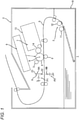
- FIG. 1 An outline of an image forming apparatus is described with reference to FIG. 1 .
- An image forming apparatus 1 includes a main body housing 2, a sheet feeding unit 3, a photosensitive drum 4, a charging device 5, an exposure device 6, a developing device 7, a transfer device 8, and a fixing device 9.
- the main body housing 2 accommodates the sheet feeding unit 3, the photosensitive drum 4, the charging device 5, the exposure device 6, the developing device 7, the transfer device 8, and the fixing device 9.
- the sheet feeding unit 3 feeds a sheet S to the photosensitive drum 4.
- the sheet feeding unit 3 includes a sheet cassette 10, a pickup roller 11, and a conveying roller 12.
- the sheet cassette 10 accommodates sheets S.
- the sheet S is, for example, a printing sheet.
- the pickup roller 11 conveys the sheet S in the sheet cassette 10 toward the conveying roller 12.
- the conveying roller 12 conveys the sheet S from the pickup roller 11 toward the photosensitive drum 4.
- the photosensitive drum 4 can rotate about an axis A.
- the axis A extends in a first direction.
- the photosensitive drum 4 has a cylindrical shape.
- the photosensitive drum 4 extends along the axis A.
- the charging device 5 electrically charges a surface of the photosensitive drum 4.
- the charging device 5 is, specifically, a charging roller.
- the charging device 5 may also be a scorotron-type charger.
- the charging device 5 is in contact with the surface of the photosensitive drum 4.
- the charging device 5 is located at an interval from the surface of the photosensitive drum 4.
- the exposure device 6 exposes the surface of the photosensitive drum 4. Specifically, the exposure device 6 exposes the surface of the photosensitive drum 4 electrically charged by the charging device 5. Thereby, an electrostatic latent image is formed on the surface of the photosensitive drum 4.
- the exposure device 6 is, specifically, a laser scan unit. Note that, the exposure device 6 may also be an LED array.
- the developing device 7 supplies toner to the surface of the photosensitive drum 4. Thereby, the electrostatic latent image is developed, so that a toner image is formed on the surface of the photosensitive drum 4.
- the developing device 7 includes a toner accommodation unit 13 and a developing roller 14.
- the toner accommodation unit 13 accommodates toner.
- Toner contains toner particles, and as required, an external additive.
- the toner particles contain a binding resin, and as required, a colorant, a pigment dispersant, a mold release agent, a magnetic material and a charge control agent.
- the binding resin is a base of the toner particles.
- the binding resin binds the components contained in the toner particles.
- the colorant imparts a desired color to the toner particles.
- the colorant is dispersed in the binding resin.
- the pigment dispersant improves dispersibility of the colorant.
- the charge control agent gives chargeability to the toner particles.
- the chargeability may be any of positive chargeability and negative chargeability.
- the external additive regulates chargeability, flowability and storage stability of the toner particles.
- the developing roller 14 supplies toner in the toner accommodation unit 13 to the surface of the photosensitive drum 4.
- the developing roller 14 is in contact with the photosensitive drum 4. Note that, the developing roller 14 may not be in contact with the photosensitive drum 4.
- the developing device 7 may be constituted as one process unit, together with the photosensitive drum 4 and the charging device 5.
- the process unit can be mounted to the main body housing 2.
- the developing device 7 may be a developing cartridge that can be mounted to a drum unit having the photosensitive drum 4 and the charging device 5.
- the drum unit can be mounted to the main body housing 2.
- the developing device 7 may also have a developing unit having the developing roller 14, and a toner cartridge that can be mounted to the developing unit.
- the toner cartridge has the toner accommodation unit 13.
- the developing unit may be provided to the drum unit. The developing unit can be mounted to the drum unit.
- the transfer device 8 transfers the toner image from the photosensitive drum 4 to the sheet S. Thereby, the toner image is formed on the sheet S.
- the transfer device 8 is in contact with the photosensitive drum 4. Note that, the transfer device 8 may not be in contact with the photosensitive drum 4.
- the transfer device 8 is, specifically, a transfer roller. Note that, the transfer device 8 may also be a transfer belt.
- the fixing device 9 provides a fixing solution to the toner image to fix the toner image on the sheet S. Specifically, the fixing device 9 sprays the ionized fixing solution toward the toner image on the sheet S by electrostatic spraying, thereby providing the fixing solution to the toner image. Then, the toner is softened by the fixing solution and then cured, so that it is fixed on the sheet S.
- the sheet S on which the toner image is fixed is discharged outside the main body housing 2.
- the fixing device 9 includes a nozzle unit 9A and an opposite electrode 9B.
- the nozzle unit 9A sprays the fixing solution to the sheet S on which the toner image is formed.
- the nozzle unit 9A includes a housing 21, a plurality of nozzles 22, a nozzle electrode 23 and a supply electrode 24.
- the housing 21 can accommodate the fixing solution.
- the housing 21 extends in the first direction.
- the first direction is a direction in which the axis A of the photosensitive drum 4 extends.
- the first direction is also a width direction of the sheet S.
- the housing 21 has an outer surface S1 and an outer surface S2 in a second direction.
- the second direction is a direction facing from the nozzle unit 9A toward the opposite electrode 9B (refer to FIG. 1 ).
- the second direction intersects with the first direction. Specifically, the second direction is orthogonal to the first direction.
- the outer surface S2 is located distant from the outer surface S1 in the second direction.
- the outer surface S2 is located closer to the opposite electrode 9B than the outer surface S1 in the second direction.
- the housing 21 has an inner surface S3 and an inner surface S4 in the second direction.
- the inner surface S4 is located distant from the inner surface S3 in the second direction.
- the inner surface S4 is located closer to the plurality of nozzles 22 than the inner surface S3 in the second direction. In other words, the inner surface S4 is located between the inner surface S3 and the plurality of nozzles 22 in the second direction.
- the housing 21 also has an inlet 211, a plurality of holes 212, an exhaust port 213, and two bosses 214A and 214B.
- the inlet 211 is located on the outer surface S1 of the housing 21.
- the inlet 211 is located at one end portion of the housing 21 in the first direction.
- the inlet 211 is formed to communicate with an internal space of the housing 21.
- the fixing solution that enters the housing 21 passes through the inlet 211.
- the image forming apparatus 1 includes a tank (not shown), a pipe (not shown), and a pump (not shown).
- the tank can accommodate a larger amount of fixing solution than the housing 21.
- the pipe connects the tank and the housing 21 each other.
- the pump pump s the fixing solution from the tank to the housing 21.
- the fixing solution in the tank is pumped to the inlet 211 of the housing 21 through the pipe by the pump.
- the pumped fixing solution passes through the inlet 211 and enters the housing 21.
- the plurality of holes 212 is located on the inner surface S4 of the housing 21.
- the plurality of holes 212 is aligned at intervals in the first direction. Specifically, the plurality of holes 212 is arranged in a zigzag form.
- the plurality of holes 212 includes a first hole 212A and a second hole 212B.
- the first hole 212A is located at one end of the plurality of holes 212 in the first direction.
- the first hole 212A is formed to communicate with an internal space of the first nozzle 22A (refer to FIG. 2 ). Thereby, the first hole 212A allows the fixing solution to enter the first nozzle 22A.
- the second hole 212B is located at the other end of the plurality of holes 212 in the first direction.
- the second hole 212B is formed to communicate with an internal space of the second nozzle 22B (refer to FIG. 2 ). Thereby, the second hole 212B allows the fixing solution to enter the second nozzle 22B.
- the exhaust port 213 is located on the outer surface S 1 of the housing 21.
- the exhaust port 213 is located at an interval from the inlet 211 in the first direction.
- the exhaust port 213 is located at the other end portion of the housing 21 in the first direction.
- the exhaust port 213 is formed to communicate with the internal space of the housing 21.
- the exhaust port 213 exhausts air in the housing 21 at a time when the fixing solution enters the housing 21.
- the boss 214A is located inside the housing 21.
- the boss 214A is located between the inlet 211 and the supply electrode 24 in the first direction.
- the boss 214A extends in a third direction.
- the third direction is a direction in which the sheet S is conveyed.
- the third direction intersects with both the first direction and the second direction.
- the boss 214A extends from the inner surface of the housing 21 in the third direction.
- the boss 214A is made of a thermoplastic resin.
- the boss 214B is located inside the housing 21.
- the boss 214B is located at an interval from the boss 214A in the first direction.
- the boss 214B is located between the exhaust port 213 and the supply electrode 24 in the first direction.
- the boss 214B extends in the third direction.
- the boss 214B extends from the inner surface of the housing 21 in the third direction.
- the boss 214B is made of a thermoplastic resin.
- the plurality of nozzles 22 is located on the outer surface S2 of the housing 21.
- the plurality of nozzles 22 is located between the nozzle electrode 23 and the opposite electrode 9B (refer to FIG. 1 ) in the second direction.
- Each of the plurality of nozzles 22 extends from the outer surface S2 of the housing 21 in the second direction.
- the plurality of nozzles 22 is aligned at intervals in the first direction.
- the plurality of nozzles 22 is arranged in a zigzag form.
- the plurality of nozzles 22 includes a first nozzle 22A and a second nozzle 22B.
- the nozzle unit 9A includes the first nozzle 22A and the second nozzle 22B.
- the first nozzle 22A and the second nozzle 22B are located on the outer surface S2 of the housing 21.
- the first nozzle 22A is located at one end of the plurality of nozzles 22 in the first direction.
- the first nozzle 22A discharges the fixing solution entering the first nozzle 22A through the first hole 212A.
- the second nozzle 22B is located at an interval from the first nozzle 22A in the first direction.
- the second nozzle 22B is located at the other end of the plurality of nozzles 22 in the first direction.
- the second nozzle 22B discharges the fixing solution entering the second nozzle 22B through the second hole 212B.
- the nozzle electrode 23 is located inside the housing 21.
- the nozzle electrode 23 extends in the first direction.
- the nozzle electrode 23 is made of metal.
- the nozzle electrode 23 has a body portion 231, a contact portion 232, and two fixing portions 232A and 232B.
- the body portion 231 is located between the plurality of nozzles 22 and the inlet 211 in the second direction.
- the nozzle electrode 23 is located between the first nozzle 22A and the inlet 211 in the second direction.
- the fixing solution entering the housing 21 from the inlet 211 contacts the body portion 231 before reaching the plurality of nozzles 22.
- the fixing solution contacting the body portion 231 is electrically charged by the voltage applied to the nozzle electrode 23. More specifically, the body portion 231 is located closer to the first nozzle 22A than the inlet 211.
- the body portion 231 is located on the inner surface S4 of the housing 21. The body portion 231 is in contact with the inner surface S4 of the housing 21.
- the body portion 231 extends in the first direction.
- the body portion 231 extends from the first hole 212A to the second hole 212B in the first direction.
- the body portion 231 extends from the first nozzle 22A to the second nozzle 22B in the first direction.
- a length L1 of the body portion 231 of the nozzle electrode 23 in the first direction is greater than an interval L2 between the first nozzle 22A and the second nozzle 22B in the first direction.
- the body portion 231 has a first end portion E1 and a second end portion E2 in the first direction.
- the second end portion E2 is located distant from the first end portion E1 in the first direction.
- the first end portion E1 of the body portion 231 is located on an opposite side to the opposite electrode 9B (refer to FIG. 1 ) with respect to the first nozzle 22A in the second direction.
- the second end portion E2 of the body portion 231 is located on an opposite side to the opposite electrode 9B with respect to the second nozzle 22B in the second direction.
- the body portion 231 has a flat plate shape. As shown in FIG. 5A , the body portion 231 has a plurality of notches 234.
- the plurality of notches 234 is aligned at intervals in the first direction.
- the plurality of notches 234 is arranged in a zigzag form.
- the plurality of notches 234 includes a first notch 234A and a second notch 234B.
- the nozzle electrode 23 has the first notch 234A and the second notch 234B.
- the first notch 234A is located at one end of the plurality of notches 234 in the first direction.
- the first notch 234A has a circular shape.
- a diameter of the first notch 234A is greater than a diameter of the first hole 212A (refer to FIG. 3 ).
- the first notch 234A is formed to communicate with the first hole 212A.
- the fixing solution contacting the body portion 231 and electrically charged enters the first hole 212A through the first notch 234A. That is, the first notch 234A allows the fixing solution to enter the first hole 212A.
- the fixing solution entering the first hole 212A is discharged from the first nozzle 22A.
- the first nozzle 22A discharges the fixing solution electrically charged by the nozzle electrode 23 from the housing 21.
- the fixing solution passing through the tip end of the first nozzle 22A is misted by an electrostatic force between the nozzle electrode 23 and the opposite electrode 9B (refer to FIG. 1 ).
- the misted fixing solution is provided to the sheet S (refer to FIG. 1 ) passing between the nozzle unit 9A and the opposite electrode 9B.
- the second notch 234B is located at the other end of the plurality of notches 234 in the first direction.
- the second notch 234B has a semicircular shape.
- a diameter of the second notch 234B is greater than a diameter of the second hole 212B (refer to FIG. 3 ).
- the second notch 234B is formed to communicate with the second hole 212B.
- the fixing solution contacting the body portion 231 and electrically charged enters the second hole 212B through the second notch 234B. That is, the second notch 234B allows the fixing solution to enter the second hole 212B.
- the fixing solution entering the second hole 212B is discharged from the second nozzle 22B.
- the second nozzle 22B discharges the fixing solution electrically charged by the nozzle electrode 23 from the housing 21.
- the fixing solution passing through the tip end of the second nozzle 22B is also misted by the electrostatic force between the nozzle electrode 23 and the opposite electrode 9B and is provided to the sheet S passing between the nozzle unit 9A and the opposite electrode 9B, similar to the fixing solution passing through the tip end of the first nozzle 22A.
- the contact portion 232 is in contact with the supply electrode 24. Thereby, the nozzle electrode 23 can receive electric power from the supply electrode 24.
- the contact portion 232 is located between the first end portion E1 and the second end portion E2 of the body portion 231 in the first direction.
- the contact portion 232 extends from the body portion 231.
- the contact portion 231 has a bent plate shape.
- the contact portion 232 has a first portion 232A and a second portion 232B.
- the first portion 232A extends from the body portion 231 in the second direction.
- the second portion 232B extends from the first portion 232A in the third direction.
- the second portion 232B is located at an interval from the body portion 231 in the second direction.
- the fixing portion 233A is fixed to an inner surface S5 of the housing 21 in the third direction.
- the inner surface S5 is located between the inner surface S3 and the inner surface S4 in the second direction.
- the inner surface S5 extends in the second direction.
- the fixing portion 233A is located between the first end portion E1 of the body portion 231 and the contact portion 232 in the first direction.
- the fixing portion 233A extends from the body portion 231 in the second direction.
- the fixing portion 233A has a flat plate shape.
- the fixing portion 233A has a through-hole.
- the boss 214A (refer to FIG. 2 ) of the housing 21 passes through the through-hole. In a state where the boss 214A passes through the through-hole of the fixing portion 233A, the boss 214A is deformed by heat caulking, so that the fixing portion 233A is fixed to the inner surface of the housing 21 in the third direction.
- the fixing portion 233B is fixed to the inner surface of the housing 21 in the third direction by heat caulking, similar to the fixing portion 233A.
- the fixing portion 233B is located between the second end portion E2 of the body portion 231 and the contact portion 232 in the first direction.
- the fixing portion 233B extends from the body portion 231 in the second direction.
- the fixing portion 233B has a flat plate shape, similar to the fixing portion 233A.
- the fixing portion 233B has a through-hole.
- the boss 214B (refer to FIG. 2 ) of the housing 21 passes through the through-hole.
- the fixing portion 233A and the fixing portion 233B are fixed to the inner surface of the housing 21 in the third direction by heat caulking, so that the nozzle electrode 23 is attached to the inner surface of the housing 21 in the third direction.
- the nozzle electrode 23 is attached to the inner surface of the housing 21 in the third direction by heat caulking.
- the supply electrode 24 is supported by the housing 21.
- the supply electrode 24 is made of metal.
- the supply electrode 24 extends in the second direction.
- the supply electrode 24 has a first end portion E11 and a second end portion E12 in the second direction.
- the first end portion E11 is located on the outer surface of the housing 21.
- the second end portion E12 is located distant from the first end portion E11 in the second direction.
- the second end portion E12 is located inside the housing 21.
- the second end portion E12 is in contact with the contact portion 232 of the nozzle electrode 23.
- the supply electrode 24 is electrically connected to the nozzle electrode 23.
- the supply electrode 24 is electrically connected to a power supply P1 (refer to FIG. 1 ) provided in the image forming apparatus 1, at the first end portion E11.
- the supply electrode 24 supplies electric power from the power supply P1 to the nozzle electrode 23.
- the opposite electrode 9B is located at an interval from the nozzle unit 9A in the second direction.
- the opposite electrode 9B extends in the first direction.
- the opposite electrode 9B is electrically connected to a power supply P2 provided in the image forming apparatus 1. Thereby, the opposite electrode 9B is applied with a voltage.
- the body portion 231 of the nozzle electrode 23 extends in the first direction.
- a length L1 of the body portion 231 of the nozzle electrode 23 in the first direction is greater than an interval L2 between the first nozzle 22A and the second nozzle 22B in the first direction.
- a distance from the nozzle electrode 23 to a tip end of the first nozzle 22A in the second direction and a distance from the nozzle electrode 23 to a tip end of the second nozzle 22B in the second direction become uniform.
- the nozzle electrode 23 is located between the plurality of nozzles 22 and the inlet 211 in the second direction.
- the fixing solution entering the housing 21 from the inlet 211 can be contacted to the body portion 231 before the fixing solution reaches the plurality of nozzles 22.
- a diameter of a notch 31 of a nozzle electrode 30 may be smaller than the diameter of the hole 212 of the housing 21.
- a diameter of a first notch 31A may be smaller than the diameter of the first hole 212A
- a diameter of a second notch 31B may also be smaller than the diameter of the second hole 212B.
- notches 41 of a nozzle electrode 40 may be formed to communicate with the plurality of holes 212.
- notches 51 of a nozzle electrode 50 may not have a circular shape.
- nozzle electrode 23 is not limited in terms of a shape as long as it extends from the first nozzle 22A to the second nozzle 22B in the first direction.
- a nozzle electrode 60 may have a circular column shape extending in the first direction.
- a nozzle electrode 70 may have a body portion 701 and a contact portion 702 without the two fixing portions 233A and 233B. Specifically, the nozzle electrode 70 mat not be attached to the inner surface of the housing 21.
- the body portion 701 extends in the first direction, similar to the body portion 231 (refer to FIG. 5A ) of the above embodiment.
- the body portion 701 has a flat plate shape.
- the body portion 701 has a plurality of notches 703.
- the contact portion 702 extends from the body portion 701, similar to the contact portion 232 (refer to FIG. 5B ) of the above embodiment.
- the contact portion 702 has a bent plate shape.
- the contact portion 702 has a first portion 702A, a second portion 702B and a hole 702C.
- the nozzle electrode 70 has one hole 702C.
- the first portion 702A extends from the body portion 701 in the second direction.
- the second portion 702B extends from the first portion 702A in the third direction.
- the second portion 702B is located at an interval from the body portion 701 in the second direction.
- the hole 702C is located at the second portion 702B.
- the hole 702C has a circular shape.
- the hole 702C is a through-hole.
- the supply electrode 24 has one projection 80.
- the projection 80 is located at the second end portion E12 of the supply electrode 23.
- the projection 80 extends from the second end portion E12 of the supply electrode 23 in the second direction.
- the projection 80 has a circular column shape.
- the projection 80 is fitted in the hole 702C.
- the nozzle unit 9A can be made smaller.
- the nozzle electrode 70 rotates with respect to the projection 80, the nozzle electrode 70 is contacted to the inner surface of the housing 21 and is thus stopped.
- the projection 80 is fitted in the hole 702C, so that it is possible to decide the position of the nozzle electrode 70 with respect to the supply electrode 24 at one place.
- the supply electrode 24 may have a hole
- the nozzle electrode 70 may have a projection that is fitted in the hole of the supply electrode 24.
- the shapes of the projection 80 and the hole 702C are not limited.
- the hole 702 C may have a quadrangular shape
- the projection 80 may have a prismatic shape.
Landscapes
- Physics & Mathematics (AREA)
- General Physics & Mathematics (AREA)
- Electrophotography Configuration And Component (AREA)
- Electrostatic Spraying Apparatus (AREA)
Abstract
Description
- The present invention relates to a fixing device.
- In the related art, a fixing device has a nozzle unit. The nozzle unit sprays a fixing solution onto a sheet on which a toner image is formed. The nozzle unit has a housing, a nozzle electrode, and a plurality of nozzles including a first nozzle and a second nozzle (refer to Patent Literature 1).
- Patent Literature 1:
JP-A-2017-68098 - In
Patent Literature 1, a distance from the nozzle electrode to the first nozzle and a distance from the nozzle electrode to the second nozzle are different. - For this reason, an amount of the fixing solution sprayed from the first nozzle and an amount of the fixing solution sprayed from the second nozzle may be different.
- It is therefore an object of the present disclosure to provide a fixing device capable of suppressing an excessive difference between an amount of a fixing solution sprayed from a first nozzle and an amount of a fixing solution sprayed from a second nozzle.
- (1) A fixing device of the present disclosure fixes a toner image on a sheet. The fixing device includes a nozzle unit.
- The nozzle unit sprays a fixing solution onto the sheet on which the toner image is formed. The nozzle unit has a housing, a nozzle electrode and a plurality of nozzles.
- The housing can accommodate the fixing solution.
- The nozzle electrode is located in the housing. The nozzle electrode extends in a first direction.
- The plurality of nozzles discharge the fixing solution electrically charged by the nozzle electrode from the housing. The plurality of nozzles are aligned in the first direction. The plurality of nozzles includes a first nozzle and a second nozzle. The second nozzle is located at an interval from the first nozzle in the first direction.
- A length of the nozzle electrode in the first direction is greater than the interval between the first nozzle and the second nozzle in the first direction.
- According to the configuration, the nozzle electrode extends in the first direction. The length of the nozzle electrode in the first direction is greater than the interval between the first nozzle and the second nozzle in the first direction.
- Thereby, a distance from the nozzle electrode to a tip end of the first nozzle in a second direction and a distance from the nozzle electrode to a tip end of the second nozzle in the second direction become uniform.
- Therefore, it is possible to suppress an excessive difference in electric charge amount of the fixing solution between the tip end of the first nozzle and the tip end of the second nozzle.
- As a result, it is possible to suppress an excessive difference between an amount of the fixing solution sprayed from the first nozzle and an amount of the fixing solution sprayed from the second nozzle.
- (2) The fixing device may further include an opposite electrode. The opposite electrode is located at an interval from the nozzle unit in a second direction intersecting with the first direction. The opposite electrode is applied with a voltage.
- (3) The first direction may intersect with a third direction in which the sheet is conveyed. The second direction may intersect with the third direction.
- (4) The first nozzle may be located at one end of the plurality of nozzles in the first direction. The second nozzle may be located at the other end of the plurality of nozzles in the first direction.
- (5) The housing may have an inlet. The fixing solution that enters the housing passes through the inlet. The nozzle electrode may be located between the plurality of nozzles and the inlet in the second direction.
- According to the configuration, it is possible to bring the fixing solution entering the housing from the inlet into contact with the nozzle electrode before the fixing solution reaches the plurality of nozzles.
- (6) The nozzle electrode may be located closer to the plurality of nozzles than the inlet in the second direction.
- (7) The plurality of nozzles may be located on an outer surface of the housing. The nozzle electrode may be located on an inner surface of the housing.
- (8) The nozzle electrode may be in contact with the inner surface of the housing.
- (9) The housing may have a first hole and a second hole. The first hole allows the fixing solution to enter the first nozzle. The second hole allows the fixing solution to enter the second nozzle. The nozzle electrode may have a first notch and a second notch. The first notch allows the fixing solution to enter the first hole. The second hole allows the fixing solution to enter the second hole.
- (10) A diameter of the first notch may be smaller than a diameter of the first hole. A diameter of the second notch may be smaller than a diameter of the second hole.
- (11) The nozzle unit may further include a supply electrode. The supply electrode supplies electric power to the nozzle electrode. The supply electrode is supported by the housing. The supply electrode may be electrically connected to the nozzle electrode.
- (12) The supply electrode may have a projection. The nozzle electrode may have a hole. The projection is fitted in the hole.
- According to the configuration, with the simple configuration where the projection of the supply electrode is fitted in the hole of the nozzle electrode, it is possible to decide a position of the nozzle electrode with respect to the housing via the supply electrode.
- (13) The nozzle electrode may be attached to the inner surface of the housing by heat caulking.
- (14) The nozzle electrode may be made of metal.
- According to the fixing device of the present disclosure, it is possible to suppress the excessive difference between the amount of the fixing solution sprayed from the first nozzle and the amount of the fixing solution sprayed from the second nozzle.
-
- [
FIG. 1] FIG. 1 is a schematic configuration view of an image forming apparatus. - [
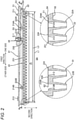
FIG. 2] FIG. 2 is a cross-sectional view of a nozzle unit shown inFIG. 1 , which is taken along a line A-A ofFIG. 4 . - [
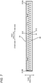
FIG. 3] FIG. 3 is a cross-sectional view of a housing shown inFIG. 2 , which is taken along a line B-B ofFIG. 2 . - [
FIG. 4] FIG. 4 is a cross-sectional view of the nozzle unit shown inFIG. 2 , which is taken along the line B-B ofFIG. 2 . - [
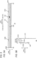
FIG. 5] FIG. 5A is a plan view of a nozzle electrode shown inFIG. 4 , andFIG. 5B is a side view of the nozzle electrode shown inFIG. 4 . - [
FIG. 6] FIG. 6 illustrates a first modified example. - [
FIG. 7] FIG. 7 illustrates a second modified example. - [
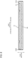
FIG. 8] FIG. 8 illustrates a third modified example. - [
FIG. 9] FIG. 9 illustrates a fourth modified example. - [
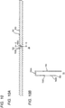
FIG. 10] FIG 10A illustrates a fifth modified example, andFIG. 10B is a cross-sectional view taken along a line C-C ofFIG. 10A . - [
FIG. 11] FIG. 11 illustrates connection of a contact portion and a supply electrode shown inFIG. 10B . - An outline of an image forming apparatus is described with reference to
FIG. 1 . - An
image forming apparatus 1 includes amain body housing 2, asheet feeding unit 3, aphotosensitive drum 4, acharging device 5, an exposure device 6, a developing device 7, atransfer device 8, and afixing device 9. - The
main body housing 2 accommodates thesheet feeding unit 3, thephotosensitive drum 4, the chargingdevice 5, the exposure device 6, the developing device 7, thetransfer device 8, and the fixingdevice 9. - The
sheet feeding unit 3 feeds a sheet S to thephotosensitive drum 4. Thesheet feeding unit 3 includes asheet cassette 10, apickup roller 11, and a conveyingroller 12. Thesheet cassette 10 accommodates sheets S. The sheet S is, for example, a printing sheet. Thepickup roller 11 conveys the sheet S in thesheet cassette 10 toward the conveyingroller 12. The conveyingroller 12 conveys the sheet S from thepickup roller 11 toward thephotosensitive drum 4. - The
photosensitive drum 4 can rotate about an axis A. The axis A extends in a first direction. Thephotosensitive drum 4 has a cylindrical shape. Thephotosensitive drum 4 extends along the axis A. - The charging
device 5 electrically charges a surface of thephotosensitive drum 4. The chargingdevice 5 is, specifically, a charging roller. Note that, the chargingdevice 5 may also be a scorotron-type charger. In a case where thecharging device 5 is a charging roller, the chargingdevice 5 is in contact with the surface of thephotosensitive drum 4. In a case where thecharging device 5 is a scorotron-type charging device, the chargingdevice 5 is located at an interval from the surface of thephotosensitive drum 4. - The exposure device 6 exposes the surface of the
photosensitive drum 4. Specifically, the exposure device 6 exposes the surface of thephotosensitive drum 4 electrically charged by the chargingdevice 5. Thereby, an electrostatic latent image is formed on the surface of thephotosensitive drum 4. The exposure device 6 is, specifically, a laser scan unit. Note that, the exposure device 6 may also be an LED array. - The developing device 7 supplies toner to the surface of the
photosensitive drum 4. Thereby, the electrostatic latent image is developed, so that a toner image is formed on the surface of thephotosensitive drum 4. The developing device 7 includes atoner accommodation unit 13 and a developingroller 14. - The
toner accommodation unit 13 accommodates toner. Toner contains toner particles, and as required, an external additive. The toner particles contain a binding resin, and as required, a colorant, a pigment dispersant, a mold release agent, a magnetic material and a charge control agent. The binding resin is a base of the toner particles. The binding resin binds the components contained in the toner particles. The colorant imparts a desired color to the toner particles. The colorant is dispersed in the binding resin. The pigment dispersant improves dispersibility of the colorant. The charge control agent gives chargeability to the toner particles. The chargeability may be any of positive chargeability and negative chargeability. The external additive regulates chargeability, flowability and storage stability of the toner particles. - The developing
roller 14 supplies toner in thetoner accommodation unit 13 to the surface of thephotosensitive drum 4. The developingroller 14 is in contact with thephotosensitive drum 4. Note that, the developingroller 14 may not be in contact with thephotosensitive drum 4. - The developing device 7 may be constituted as one process unit, together with the
photosensitive drum 4 and thecharging device 5. The process unit can be mounted to themain body housing 2. - In addition, the developing device 7 may be a developing cartridge that can be mounted to a drum unit having the
photosensitive drum 4 and thecharging device 5. The drum unit can be mounted to themain body housing 2. - The developing device 7 may also have a developing unit having the developing
roller 14, and a toner cartridge that can be mounted to the developing unit. In this case, the toner cartridge has thetoner accommodation unit 13. In addition, the developing unit may be provided to the drum unit. The developing unit can be mounted to the drum unit. - The
transfer device 8 transfers the toner image from thephotosensitive drum 4 to the sheet S. Thereby, the toner image is formed on the sheet S. Thetransfer device 8 is in contact with thephotosensitive drum 4. Note that, thetransfer device 8 may not be in contact with thephotosensitive drum 4. Thetransfer device 8 is, specifically, a transfer roller. Note that, thetransfer device 8 may also be a transfer belt. - The fixing
device 9 provides a fixing solution to the toner image to fix the toner image on the sheet S. Specifically, the fixingdevice 9 sprays the ionized fixing solution toward the toner image on the sheet S by electrostatic spraying, thereby providing the fixing solution to the toner image. Then, the toner is softened by the fixing solution and then cured, so that it is fixed on the sheet S. The sheet S on which the toner image is fixed is discharged outside themain body housing 2. - Subsequently, details of the fixing
device 9 are described with reference toFIGs. 1 to 5 . - As shown in
FIG. 1 , the fixingdevice 9 includes anozzle unit 9A and anopposite electrode 9B. - The
nozzle unit 9A sprays the fixing solution to the sheet S on which the toner image is formed. As shown inFIG. 2 , thenozzle unit 9A includes ahousing 21, a plurality ofnozzles 22, anozzle electrode 23 and asupply electrode 24. - The
housing 21 can accommodate the fixing solution. Thehousing 21 extends in the first direction. The first direction is a direction in which the axis A of thephotosensitive drum 4 extends. The first direction is also a width direction of the sheet S. Thehousing 21 has an outer surface S1 and an outer surface S2 in a second direction. The second direction is a direction facing from thenozzle unit 9A toward theopposite electrode 9B (refer toFIG. 1 ). The second direction intersects with the first direction. Specifically, the second direction is orthogonal to the first direction. The outer surface S2 is located distant from the outer surface S1 in the second direction. The outer surface S2 is located closer to theopposite electrode 9B than the outer surface S1 in the second direction. Thehousing 21 has an inner surface S3 and an inner surface S4 in the second direction. The inner surface S4 is located distant from the inner surface S3 in the second direction. The inner surface S4 is located closer to the plurality ofnozzles 22 than the inner surface S3 in the second direction. In other words, the inner surface S4 is located between the inner surface S3 and the plurality ofnozzles 22 in the second direction. Thehousing 21 also has aninlet 211, a plurality ofholes 212, anexhaust port 213, and twobosses - The
inlet 211 is located on the outer surface S1 of thehousing 21. Theinlet 211 is located at one end portion of thehousing 21 in the first direction. Theinlet 211 is formed to communicate with an internal space of thehousing 21. The fixing solution that enters thehousing 21 passes through theinlet 211. Specifically, theimage forming apparatus 1 includes a tank (not shown), a pipe (not shown), and a pump (not shown). The tank can accommodate a larger amount of fixing solution than thehousing 21. The pipe connects the tank and thehousing 21 each other. The pump pump s the fixing solution from the tank to thehousing 21. The fixing solution in the tank is pumped to theinlet 211 of thehousing 21 through the pipe by the pump. The pumped fixing solution passes through theinlet 211 and enters thehousing 21. - As shown in
FIG. 3 , the plurality ofholes 212 is located on the inner surface S4 of thehousing 21. The plurality ofholes 212 is aligned at intervals in the first direction. Specifically, the plurality ofholes 212 is arranged in a zigzag form. The plurality ofholes 212 includes afirst hole 212A and asecond hole 212B. - The
first hole 212A is located at one end of the plurality ofholes 212 in the first direction. Thefirst hole 212A is formed to communicate with an internal space of thefirst nozzle 22A (refer toFIG. 2 ). Thereby, thefirst hole 212A allows the fixing solution to enter thefirst nozzle 22A. - The
second hole 212B is located at the other end of the plurality ofholes 212 in the first direction. Thesecond hole 212B is formed to communicate with an internal space of thesecond nozzle 22B (refer toFIG. 2 ). Thereby, thesecond hole 212B allows the fixing solution to enter thesecond nozzle 22B. - As shown in
FIG. 2 , theexhaust port 213 is located on theouter surface S 1 of thehousing 21. Theexhaust port 213 is located at an interval from theinlet 211 in the first direction. Theexhaust port 213 is located at the other end portion of thehousing 21 in the first direction. Theexhaust port 213 is formed to communicate with the internal space of thehousing 21. Theexhaust port 213 exhausts air in thehousing 21 at a time when the fixing solution enters thehousing 21. - As shown in
FIG. 2 , theboss 214A is located inside thehousing 21. Theboss 214A is located between theinlet 211 and thesupply electrode 24 in the first direction. Theboss 214A extends in a third direction. The third direction is a direction in which the sheet S is conveyed. The third direction intersects with both the first direction and the second direction. Theboss 214A extends from the inner surface of thehousing 21 in the third direction. Theboss 214A is made of a thermoplastic resin. - The
boss 214B is located inside thehousing 21. Theboss 214B is located at an interval from theboss 214A in the first direction. Theboss 214B is located between theexhaust port 213 and thesupply electrode 24 in the first direction. Theboss 214B extends in the third direction. Theboss 214B extends from the inner surface of thehousing 21 in the third direction. Theboss 214B is made of a thermoplastic resin. - As shown in
FIG. 2 , the plurality ofnozzles 22 is located on the outer surface S2 of thehousing 21. The plurality ofnozzles 22 is located between thenozzle electrode 23 and theopposite electrode 9B (refer toFIG. 1 ) in the second direction. Each of the plurality ofnozzles 22 extends from the outer surface S2 of thehousing 21 in the second direction. The plurality ofnozzles 22 is aligned at intervals in the first direction. Specifically, the plurality ofnozzles 22 is arranged in a zigzag form. The plurality ofnozzles 22 includes afirst nozzle 22A and asecond nozzle 22B. In other words, thenozzle unit 9A includes thefirst nozzle 22A and thesecond nozzle 22B. Thefirst nozzle 22A and thesecond nozzle 22B are located on the outer surface S2 of thehousing 21. - The
first nozzle 22A is located at one end of the plurality ofnozzles 22 in the first direction. Thefirst nozzle 22A discharges the fixing solution entering thefirst nozzle 22A through thefirst hole 212A. - The
second nozzle 22B is located at an interval from thefirst nozzle 22A in the first direction. Thesecond nozzle 22B is located at the other end of the plurality ofnozzles 22 in the first direction. Thesecond nozzle 22B discharges the fixing solution entering thesecond nozzle 22B through thesecond hole 212B. - As shown in
FIGs. 2 and4 , thenozzle electrode 23 is located inside thehousing 21. Thenozzle electrode 23 extends in the first direction. Thenozzle electrode 23 is made of metal. As shown inFIGs. 5A and 5B , thenozzle electrode 23 has abody portion 231, acontact portion 232, and two fixingportions - As shown in
FIG. 2 , thebody portion 231 is located between the plurality ofnozzles 22 and theinlet 211 in the second direction. Specifically, thenozzle electrode 23 is located between thefirst nozzle 22A and theinlet 211 in the second direction. Thereby, the fixing solution entering thehousing 21 from theinlet 211 contacts thebody portion 231 before reaching the plurality ofnozzles 22. The fixing solution contacting thebody portion 231 is electrically charged by the voltage applied to thenozzle electrode 23. More specifically, thebody portion 231 is located closer to thefirst nozzle 22A than theinlet 211. Thebody portion 231 is located on the inner surface S4 of thehousing 21. Thebody portion 231 is in contact with the inner surface S4 of thehousing 21. - As shown in
FIGs. 2 and4 , thebody portion 231 extends in the first direction. Thebody portion 231 extends from thefirst hole 212A to thesecond hole 212B in the first direction. In other words, thebody portion 231 extends from thefirst nozzle 22A to thesecond nozzle 22B in the first direction. A length L1 of thebody portion 231 of thenozzle electrode 23 in the first direction is greater than an interval L2 between thefirst nozzle 22A and thesecond nozzle 22B in the first direction. Thereby, distances from thenozzle electrode 23 to tip ends of each of the plurality ofnozzles 22 in the second direction become uniform. For this reason, electric charge amounts of the fixing solution at the tip ends of each of the plurality ofnozzles 22 become uniform. - Specifically, the
body portion 231 has a first end portion E1 and a second end portion E2 in the first direction. The second end portion E2 is located distant from the first end portion E1 in the first direction. The first end portion E1 of thebody portion 231 is located on an opposite side to theopposite electrode 9B (refer toFIG. 1 ) with respect to thefirst nozzle 22A in the second direction. The second end portion E2 of thebody portion 231 is located on an opposite side to theopposite electrode 9B with respect to thesecond nozzle 22B in the second direction. Thebody portion 231 has a flat plate shape. As shown inFIG. 5A , thebody portion 231 has a plurality ofnotches 234. - The plurality of
notches 234 is aligned at intervals in the first direction. The plurality ofnotches 234 is arranged in a zigzag form. The plurality ofnotches 234 includes afirst notch 234A and asecond notch 234B. In other words, thenozzle electrode 23 has thefirst notch 234A and thesecond notch 234B. - The
first notch 234A is located at one end of the plurality ofnotches 234 in the first direction. Thefirst notch 234A has a circular shape. A diameter of thefirst notch 234A is greater than a diameter of thefirst hole 212A (refer toFIG. 3 ). As shown inFIG. 2 , thefirst notch 234A is formed to communicate with thefirst hole 212A. Thereby, the fixing solution contacting thebody portion 231 and electrically charged enters thefirst hole 212A through thefirst notch 234A. That is, thefirst notch 234A allows the fixing solution to enter thefirst hole 212A. The fixing solution entering thefirst hole 212A is discharged from thefirst nozzle 22A. Specifically, thefirst nozzle 22A discharges the fixing solution electrically charged by thenozzle electrode 23 from thehousing 21. At this time, the fixing solution passing through the tip end of thefirst nozzle 22A is misted by an electrostatic force between thenozzle electrode 23 and theopposite electrode 9B (refer toFIG. 1 ). The misted fixing solution is provided to the sheet S (refer toFIG. 1 ) passing between thenozzle unit 9A and theopposite electrode 9B. - The
second notch 234B is located at the other end of the plurality ofnotches 234 in the first direction. Thesecond notch 234B has a semicircular shape. A diameter of thesecond notch 234B is greater than a diameter of thesecond hole 212B (refer toFIG. 3 ). As shown inFIG. 2 , thesecond notch 234B is formed to communicate with thesecond hole 212B. Thereby, the fixing solution contacting thebody portion 231 and electrically charged enters thesecond hole 212B through thesecond notch 234B. That is, thesecond notch 234B allows the fixing solution to enter thesecond hole 212B. The fixing solution entering thesecond hole 212B is discharged from thesecond nozzle 22B. Specifically, thesecond nozzle 22B discharges the fixing solution electrically charged by thenozzle electrode 23 from thehousing 21. At this time, the fixing solution passing through the tip end of thesecond nozzle 22B is also misted by the electrostatic force between thenozzle electrode 23 and theopposite electrode 9B and is provided to the sheet S passing between thenozzle unit 9A and theopposite electrode 9B, similar to the fixing solution passing through the tip end of thefirst nozzle 22A. - As shown in
FIG. 2 , thecontact portion 232 is in contact with thesupply electrode 24. Thereby, thenozzle electrode 23 can receive electric power from thesupply electrode 24. As shown inFIG. 5A , thecontact portion 232 is located between the first end portion E1 and the second end portion E2 of thebody portion 231 in the first direction. As shown inFIG. 5B , thecontact portion 232 extends from thebody portion 231. Specifically, thecontact portion 231 has a bent plate shape. Thecontact portion 232 has afirst portion 232A and asecond portion 232B. - The
first portion 232A extends from thebody portion 231 in the second direction. - The
second portion 232B extends from thefirst portion 232A in the third direction. Thesecond portion 232B is located at an interval from thebody portion 231 in the second direction. - As shown in
FIG. 4 , the fixingportion 233A is fixed to an inner surface S5 of thehousing 21 in the third direction. The inner surface S5 is located between the inner surface S3 and the inner surface S4 in the second direction. The inner surface S5 extends in the second direction. Specifically, as shown inFIG. 5A , the fixingportion 233A is located between the first end portion E1 of thebody portion 231 and thecontact portion 232 in the first direction. As shown inFIG. 5B , the fixingportion 233A extends from thebody portion 231 in the second direction. The fixingportion 233A has a flat plate shape. The fixingportion 233A has a through-hole. Theboss 214A (refer toFIG. 2 ) of thehousing 21 passes through the through-hole. In a state where theboss 214A passes through the through-hole of the fixingportion 233A, theboss 214A is deformed by heat caulking, so that the fixingportion 233A is fixed to the inner surface of thehousing 21 in the third direction. - As shown in
FIG. 4 , the fixingportion 233B is fixed to the inner surface of thehousing 21 in the third direction by heat caulking, similar to the fixingportion 233A. Specifically, as shown inFIG. 5A , the fixingportion 233B is located between the second end portion E2 of thebody portion 231 and thecontact portion 232 in the first direction. As shown inFIG. 5B , the fixingportion 233B extends from thebody portion 231 in the second direction. The fixingportion 233B has a flat plate shape, similar to the fixingportion 233A. The fixingportion 233B has a through-hole. Theboss 214B (refer toFIG. 2 ) of thehousing 21 passes through the through-hole. - As shown in
FIG. 4 , the fixingportion 233A and the fixingportion 233B are fixed to the inner surface of thehousing 21 in the third direction by heat caulking, so that thenozzle electrode 23 is attached to the inner surface of thehousing 21 in the third direction. Specifically, thenozzle electrode 23 is attached to the inner surface of thehousing 21 in the third direction by heat caulking. - As shown in
FIG. 2 , thesupply electrode 24 is supported by thehousing 21. Thesupply electrode 24 is made of metal. Thesupply electrode 24 extends in the second direction. Thesupply electrode 24 has a first end portion E11 and a second end portion E12 in the second direction. The first end portion E11 is located on the outer surface of thehousing 21. The second end portion E12 is located distant from the first end portion E11 in the second direction. The second end portion E12 is located inside thehousing 21. The second end portion E12 is in contact with thecontact portion 232 of thenozzle electrode 23. Thereby, thesupply electrode 24 is electrically connected to thenozzle electrode 23. In addition, thesupply electrode 24 is electrically connected to a power supply P1 (refer toFIG. 1 ) provided in theimage forming apparatus 1, at the first end portion E11. Thereby, thesupply electrode 24 supplies electric power from the power supply P1 to thenozzle electrode 23. - As shown in
FIG. 1 , theopposite electrode 9B is located at an interval from thenozzle unit 9A in the second direction. Theopposite electrode 9B extends in the first direction. Theopposite electrode 9B is electrically connected to a power supply P2 provided in theimage forming apparatus 1. Thereby, theopposite electrode 9B is applied with a voltage. - As shown in
FIGs. 2 and4 , according to thefixing device 9, thebody portion 231 of thenozzle electrode 23 extends in the first direction. A length L1 of thebody portion 231 of thenozzle electrode 23 in the first direction is greater than an interval L2 between thefirst nozzle 22A and thesecond nozzle 22B in the first direction. - Thereby, a distance from the
nozzle electrode 23 to a tip end of thefirst nozzle 22A in the second direction and a distance from thenozzle electrode 23 to a tip end of thesecond nozzle 22B in the second direction become uniform. - Therefore, it is possible to suppress an excessive difference in electric charge amount of the fixing solution between the tip end of the
first nozzle 22A and the tip end of thesecond nozzle 22B. - As a result, it is possible to suppress an excessive difference between an amount of the fixing solution sprayed from the
first nozzle 22A and an amount of the fixing solution sprayed from thesecond nozzle 22B. - In addition, as shown in
FIG. 2 , according to thefixing device 9, thenozzle electrode 23 is located between the plurality ofnozzles 22 and theinlet 211 in the second direction. - Thereby, the fixing solution entering the
housing 21 from theinlet 211 can be contacted to thebody portion 231 before the fixing solution reaches the plurality ofnozzles 22. - Modified examples are described with reference to
FIGs. 6 to 11 . Note that, in the modified examples, the same members as the above embodiment are denoted with the same reference signs, and the descriptions thereof are omitted. - (1) The
notch 234 of thenozzle electrode 23 is not limited in terms of a size and a shape as long as thenotch 234 can allow the fixing solution to enter thenozzle 22. - For example, as shown in
FIG. 6 , a diameter of anotch 31 of anozzle electrode 30 may be smaller than the diameter of thehole 212 of thehousing 21. Specifically, a diameter of a first notch 31A may be smaller than the diameter of thefirst hole 212A, and a diameter of a second notch 31B may also be smaller than the diameter of thesecond hole 212B. In addition, as shown inFIG. 7 ,notches 41 of anozzle electrode 40 may be formed to communicate with the plurality ofholes 212. In addition, as shown inFIG. 8 ,notches 51 of anozzle electrode 50 may not have a circular shape. - Further, the
nozzle electrode 23 is not limited in terms of a shape as long as it extends from thefirst nozzle 22A to thesecond nozzle 22B in the first direction. For example, as shown inFIG. 9 , anozzle electrode 60 may have a circular column shape extending in the first direction. - Also in these modified examples, the operational effects similar to the above embodiment can be realized.
- (2) As shown in
FIG. 10A , anozzle electrode 70 may have abody portion 701 and acontact portion 702 without the two fixingportions nozzle electrode 70 mat not be attached to the inner surface of thehousing 21. - The
body portion 701 extends in the first direction, similar to the body portion 231 (refer toFIG. 5A ) of the above embodiment. Thebody portion 701 has a flat plate shape. Thebody portion 701 has a plurality ofnotches 703. - As shown in
FIG. 10B , thecontact portion 702 extends from thebody portion 701, similar to the contact portion 232 (refer toFIG. 5B ) of the above embodiment. Thecontact portion 702 has a bent plate shape. Thecontact portion 702 has afirst portion 702A, asecond portion 702B and ahole 702C. In other words, thenozzle electrode 70 has onehole 702C. - The
first portion 702A extends from thebody portion 701 in the second direction. - The
second portion 702B extends from thefirst portion 702A in the third direction. Thesecond portion 702B is located at an interval from thebody portion 701 in the second direction. - The
hole 702C is located at thesecond portion 702B. Thehole 702C has a circular shape. Thehole 702C is a through-hole. - As shown in
FIG. 11 , thesupply electrode 24 has oneprojection 80. - The
projection 80 is located at the second end portion E12 of thesupply electrode 23. Theprojection 80 extends from the second end portion E12 of thesupply electrode 23 in the second direction. Theprojection 80 has a circular column shape. Theprojection 80 is fitted in thehole 702C. - Also in the modified example, the operational effects similar to the above embodiment can be realized.
- Further, according to this modified example, with the simple configuration where the
nozzle electrode 70 does not have the two fixingportions projection 80 is fitted in thehole 702C, it is possible to easily decide a position of thenozzle electrode 70 with respect to thehousing 21 via thesupply electrode 24. - For this reason, as compared to the configuration where the
nozzle electrode 70 is attached to thehousing 21 with the two fixingportions nozzle unit 9A can be made smaller. - Note that, when the
nozzle electrode 70 rotates with respect to theprojection 80, thenozzle electrode 70 is contacted to the inner surface of thehousing 21 and is thus stopped. - In addition, the
projection 80 is fitted in thehole 702C, so that it is possible to decide the position of thenozzle electrode 70 with respect to thesupply electrode 24 at one place. - For this reason, it is possible to suppress a force, which is caused due to a difference in linear expansion between the
nozzle electrode 70 and thehousing 21, from being applied to thenozzle electrode 70. - (3) In the modified example (2), the
supply electrode 24 may have a hole, and thenozzle electrode 70 may have a projection that is fitted in the hole of thesupply electrode 24. - The shapes of the
projection 80 and thehole 702C are not limited. For example, thehole 702 C may have a quadrangular shape, and theprojection 80 may have a prismatic shape. - (4) The plurality of modified examples may be combined with each other.
-
- 9:
- fixing device
- 9A:
- nozzle unit
- 9B:
- opposite electrode
- 21:
- housing
- 211:
- inlet
- 212A:
- first hole
- 212B:
- second hole
- 22:
- nozzle
- 22A:
- first nozzle
- 22B:
- second nozzle
- 23:
- nozzle electrode
- 234A:
- first notch
- 234B:
- second notch
- 24:
- supply electrode
- 30:
- nozzle electrode
- 31A:
- first notch
- 31B:
- second notch
- 40:
- nozzle electrode
- 50:
- nozzle electrode
- 60:
- nozzle electrode
- 70:
- nozzle electrode
- 702C:
- hole
- 80:
- projection
Claims (14)
- A fixing device comprising a nozzle unit that sprays a fixing solution to a sheet on which a toner image is formed, and provided to fix the toner image on the sheet,wherein the nozzle unit comprises:a housing capable of accommodating the fixing solution;a nozzle electrode located inside the housing and extending in a first direction; anda plurality of nozzles provided to discharge the fixing solution electrically charged by the nozzle electrode from the housing, aligned along the first direction, and comprising a first nozzle and a second nozzle located at an interval from the first nozzle in the first direction, anda length of the nozzle electrode in the first direction is greater than the interval between the first nozzle and the second nozzle in the first direction.
- The fixing device according to claim 1, further comprising an opposite electrode located at an interval from the nozzle unit in a second direction intersecting with the first direction, a voltage being applied to the opposite electrode.
- The fixing device according to claim 2,wherein the first direction intersects with a third direction in which the sheet is conveyed, andthe second direction intersects with the third direction.
- The fixing device according to any one of claims 1 to 3,wherein the first nozzle is located at one end of the plurality of nozzles in the first direction, andthe second nozzle is located at the other end of the plurality of nozzles in the first direction.
- The fixing device according to claim 2 or 3,wherein the housing has an inlet through which the fixing solution entering the housing passes, andthe nozzle electrode is located between the plurality of nozzles and the inlet in the second direction.
- The fixing device according to claim 5,
wherein the nozzle electrode is located closer to the plurality of nozzles than the inlet in the second direction. - The fixing device according to any one of claims 1 to 6,wherein the plurality of nozzles are located on an outer surface of the housing, andthe nozzle electrode is located on an inner surface of the housing.
- The fixing device according to claim 7,
wherein the nozzle electrode is in contact with the inner surface of the housing. - The fixing device according to any one of claims 1 to 8,wherein the housing has a first hole allowing the fixing solution to enter the first nozzle and a second hole allowing the fixing solution to enter the second nozzle, andthe nozzle electrode has a first notch allowing the fixing solution to enter the first hole and a second notch allowing the fixing solution to enter the second hole.
- The fixing device according to claim 9,wherein a diameter of the first notch is smaller than a diameter of the first hole, anda diameter of the second notch is smaller than a diameter of the second hole.
- The fixing device according to any one of claims 1 to 10,
wherein the nozzle unit further comprises a supply electrode provided to supply electric power to the nozzle electrode, supported by the housing, and electrically connected to the nozzle electrode. - The fixing device according to claim 11,wherein the supply electrode has a projection, andthe nozzle electrode has a hole in which the projection is fitted.
- The fixing device according to claim 8,
wherein the nozzle electrode is attached to the inner surface of the housing by heat caulking. - The fixing device according to any one of claims 1 to 13,
wherein the nozzle electrode is made of metal.
Applications Claiming Priority (3)
| Application Number | Priority Date | Filing Date | Title |
|---|---|---|---|
| JP2019063821 | 2019-03-28 | ||
| JP2019219836A JP7415500B2 (en) | 2019-03-28 | 2019-12-04 | Fusing device |
| PCT/JP2019/051138 WO2020194969A1 (en) | 2019-03-28 | 2019-12-26 | Fixing device |
Publications (3)
| Publication Number | Publication Date |
|---|---|
| EP3951504A1 true EP3951504A1 (en) | 2022-02-09 |
| EP3951504A4 EP3951504A4 (en) | 2022-10-12 |
| EP3951504B1 EP3951504B1 (en) | 2024-06-19 |
Family
ID=72610767
Family Applications (1)
| Application Number | Title | Priority Date | Filing Date |
|---|---|---|---|
| EP19922022.9A Active EP3951504B1 (en) | 2019-03-28 | 2019-12-26 | Fixing device |
Country Status (3)
| Country | Link |
|---|---|
| US (1) | US11635719B2 (en) |
| EP (1) | EP3951504B1 (en) |
| WO (1) | WO2020194969A1 (en) |
Families Citing this family (1)
| Publication number | Priority date | Publication date | Assignee | Title |
|---|---|---|---|---|
| CN115514295A (en) | 2022-10-25 | 2022-12-23 | 上海晨科太阳能科技有限公司 | Photovoltaic panel fixing device |
Family Cites Families (13)
| Publication number | Priority date | Publication date | Assignee | Title |
|---|---|---|---|---|
| JPS4749617B1 (en) * | 1967-04-19 | 1972-12-13 | ||
| JPS6287975A (en) * | 1985-10-14 | 1987-04-22 | Canon Inc | image forming device |
| JP4549464B2 (en) * | 1999-11-16 | 2010-09-22 | 大日本印刷株式会社 | Field discharge head, field discharge control device, and field discharge coating device |
| US7360724B2 (en) * | 2004-10-20 | 2008-04-22 | The Procter & Gamble Company | Electrostatic spray nozzle with internal and external electrodes |
| JP2010032858A (en) | 2008-07-30 | 2010-02-12 | Canon Finetech Inc | Fixing method and fixing device |
| JP5742162B2 (en) * | 2009-10-27 | 2015-07-01 | 株式会社リコー | Energizing mechanism, image carrier unit, process cartridge, belt unit, and image forming apparatus |
| EP2317394B1 (en) | 2009-10-27 | 2017-05-10 | Ricoh Company Ltd. | Mechanism for Electrifying, Method of Electrifying, and Conductive Member |
| US20130287962A1 (en) * | 2012-04-25 | 2013-10-31 | University Of Central Florida Research Foundation Inc. | Electrospray atomization electrode, nozzle, apparatus, methods and applications |
| JP2017068098A (en) | 2015-09-30 | 2017-04-06 | ブラザー工業株式会社 | Spraying device, fixing device, and image forming apparatus |
| JP2017167245A (en) * | 2016-03-15 | 2017-09-21 | ブラザー工業株式会社 | Fixing device |
| CN108139707B (en) * | 2015-09-30 | 2021-10-19 | 兄弟工业株式会社 | Fixing device |
| JP2017122805A (en) * | 2016-01-06 | 2017-07-13 | 富士ゼロックス株式会社 | Fixing device and image forming apparatus |
| US10254690B2 (en) * | 2016-06-20 | 2019-04-09 | Toshiba Tec Kabushiki Kaisha | Heater and fixing device |
-
2019
- 2019-12-26 EP EP19922022.9A patent/EP3951504B1/en active Active
- 2019-12-26 WO PCT/JP2019/051138 patent/WO2020194969A1/en not_active Ceased
-
2021
- 2021-09-28 US US17/487,267 patent/US11635719B2/en active Active
Also Published As
| Publication number | Publication date |
|---|---|
| WO2020194969A1 (en) | 2020-10-01 |
| EP3951504B1 (en) | 2024-06-19 |
| US11635719B2 (en) | 2023-04-25 |
| EP3951504A4 (en) | 2022-10-12 |
| US20220011700A1 (en) | 2022-01-13 |
Similar Documents
| Publication | Publication Date | Title |
|---|---|---|
| EP1953603B1 (en) | Process unit, image apparatus, and developing cartridge | |
| US8005392B2 (en) | Image forming device with pressing members, process cartridge, and developer cartridge | |
| US9213305B2 (en) | Developing cartridge | |
| US6922536B2 (en) | Process cartridge and electrophotographic image forming apparatus | |
| CN103217879B (en) | For electrode and the image forming apparatus of image forming apparatus | |
| US20130170851A1 (en) | Cartridge | |
| EP3951504B1 (en) | Fixing device | |
| US9645538B2 (en) | Developing device, and image forming apparatus and process cartridge incorporating same | |
| CN101276193B (en) | Photosensitive medium supporting apparatus, display box, imaging device and display box mounting and dismounting method | |
| US12253811B2 (en) | Developing device | |
| JP4665927B2 (en) | Cartridge and image forming apparatus | |
| JP7415500B2 (en) | Fusing device | |
| US9651897B2 (en) | Image forming apparatus apparatus positioning magnets by contact faces of shaft and bearing and restraining action of force from guide part by clearance between shaft and bearing | |
| US20160018785A1 (en) | Image forming apparatus and process cartridge | |
| CN210402019U (en) | Carbon powder box | |
| EP3951503B1 (en) | Fixing device | |
| US10496012B1 (en) | Developing device and image forming apparatus | |
| US8412078B2 (en) | Development agent supply device including an electric-field transfer board and a development agent retrieving unit and image forming apparatus having the same | |
| WO2020194836A1 (en) | Fixing device and image forming device | |
| JP7415501B2 (en) | Fusing device | |
| CN101535902A (en) | Grounding assembly for a drum in an image forming apparatus | |
| CN102906645A (en) | Electrification device and image forming device | |
| US20100239315A1 (en) | Image Forming Device Employing Charger for Charging Photosensitive Member | |
| JP2005195632A (en) | Image forming apparatus | |
| US9383682B1 (en) | Developing device including a first transport path and a second transport path including a plurality of flow paths and image forming apparatus |
Legal Events
| Date | Code | Title | Description |
|---|---|---|---|
| STAA | Information on the status of an ep patent application or granted ep patent |
Free format text: STATUS: THE INTERNATIONAL PUBLICATION HAS BEEN MADE |
|
| PUAI | Public reference made under article 153(3) epc to a published international application that has entered the european phase |
Free format text: ORIGINAL CODE: 0009012 |
|
| STAA | Information on the status of an ep patent application or granted ep patent |
Free format text: STATUS: REQUEST FOR EXAMINATION WAS MADE |
|
| 17P | Request for examination filed |
Effective date: 20210927 |
|
| AK | Designated contracting states |
Kind code of ref document: A1 Designated state(s): AL AT BE BG CH CY CZ DE DK EE ES FI FR GB GR HR HU IE IS IT LI LT LU LV MC MK MT NL NO PL PT RO RS SE SI SK SM TR |
|
| DAV | Request for validation of the european patent (deleted) | ||
| DAX | Request for extension of the european patent (deleted) | ||
| A4 | Supplementary search report drawn up and despatched |
Effective date: 20220909 |
|
| RIC1 | Information provided on ipc code assigned before grant |
Ipc: G03G 15/20 20060101AFI20220905BHEP |
|
| P01 | Opt-out of the competence of the unified patent court (upc) registered |
Effective date: 20230529 |
|
| GRAP | Despatch of communication of intention to grant a patent |
Free format text: ORIGINAL CODE: EPIDOSNIGR1 |
|
| STAA | Information on the status of an ep patent application or granted ep patent |
Free format text: STATUS: GRANT OF PATENT IS INTENDED |
|
| INTG | Intention to grant announced |
Effective date: 20240115 |
|
| GRAS | Grant fee paid |
Free format text: ORIGINAL CODE: EPIDOSNIGR3 |
|
| GRAA | (expected) grant |
Free format text: ORIGINAL CODE: 0009210 |
|
| STAA | Information on the status of an ep patent application or granted ep patent |
Free format text: STATUS: THE PATENT HAS BEEN GRANTED |
|
| AK | Designated contracting states |
Kind code of ref document: B1 Designated state(s): AL AT BE BG CH CY CZ DE DK EE ES FI FR GB GR HR HU IE IS IT LI LT LU LV MC MK MT NL NO PL PT RO RS SE SI SK SM TR |
|
| REG | Reference to a national code |
Ref country code: GB Ref legal event code: FG4D |
|
| REG | Reference to a national code |
Ref country code: CH Ref legal event code: EP |
|
| REG | Reference to a national code |
Ref country code: DE Ref legal event code: R096 Ref document number: 602019054051 Country of ref document: DE |
|
| PG25 | Lapsed in a contracting state [announced via postgrant information from national office to epo] |
Ref country code: BG Free format text: LAPSE BECAUSE OF FAILURE TO SUBMIT A TRANSLATION OF THE DESCRIPTION OR TO PAY THE FEE WITHIN THE PRESCRIBED TIME-LIMIT Effective date: 20240619 |
|
| PG25 | Lapsed in a contracting state [announced via postgrant information from national office to epo] |
Ref country code: HR Free format text: LAPSE BECAUSE OF FAILURE TO SUBMIT A TRANSLATION OF THE DESCRIPTION OR TO PAY THE FEE WITHIN THE PRESCRIBED TIME-LIMIT Effective date: 20240619 Ref country code: FI Free format text: LAPSE BECAUSE OF FAILURE TO SUBMIT A TRANSLATION OF THE DESCRIPTION OR TO PAY THE FEE WITHIN THE PRESCRIBED TIME-LIMIT Effective date: 20240619 |
|
| REG | Reference to a national code |
Ref country code: LT Ref legal event code: MG9D |
|
| PG25 | Lapsed in a contracting state [announced via postgrant information from national office to epo] |
Ref country code: GR Free format text: LAPSE BECAUSE OF FAILURE TO SUBMIT A TRANSLATION OF THE DESCRIPTION OR TO PAY THE FEE WITHIN THE PRESCRIBED TIME-LIMIT Effective date: 20240920 |
|
| REG | Reference to a national code |
Ref country code: NL Ref legal event code: MP Effective date: 20240619 |
|
| PG25 | Lapsed in a contracting state [announced via postgrant information from national office to epo] |
Ref country code: LV Free format text: LAPSE BECAUSE OF FAILURE TO SUBMIT A TRANSLATION OF THE DESCRIPTION OR TO PAY THE FEE WITHIN THE PRESCRIBED TIME-LIMIT Effective date: 20240619 |
|
| PG25 | Lapsed in a contracting state [announced via postgrant information from national office to epo] |
Ref country code: NO Free format text: LAPSE BECAUSE OF FAILURE TO SUBMIT A TRANSLATION OF THE DESCRIPTION OR TO PAY THE FEE WITHIN THE PRESCRIBED TIME-LIMIT Effective date: 20240919 Ref country code: LV Free format text: LAPSE BECAUSE OF FAILURE TO SUBMIT A TRANSLATION OF THE DESCRIPTION OR TO PAY THE FEE WITHIN THE PRESCRIBED TIME-LIMIT Effective date: 20240619 Ref country code: HR Free format text: LAPSE BECAUSE OF FAILURE TO SUBMIT A TRANSLATION OF THE DESCRIPTION OR TO PAY THE FEE WITHIN THE PRESCRIBED TIME-LIMIT Effective date: 20240619 Ref country code: GR Free format text: LAPSE BECAUSE OF FAILURE TO SUBMIT A TRANSLATION OF THE DESCRIPTION OR TO PAY THE FEE WITHIN THE PRESCRIBED TIME-LIMIT Effective date: 20240920 Ref country code: FI Free format text: LAPSE BECAUSE OF FAILURE TO SUBMIT A TRANSLATION OF THE DESCRIPTION OR TO PAY THE FEE WITHIN THE PRESCRIBED TIME-LIMIT Effective date: 20240619 Ref country code: BG Free format text: LAPSE BECAUSE OF FAILURE TO SUBMIT A TRANSLATION OF THE DESCRIPTION OR TO PAY THE FEE WITHIN THE PRESCRIBED TIME-LIMIT Effective date: 20240619 Ref country code: RS Free format text: LAPSE BECAUSE OF FAILURE TO SUBMIT A TRANSLATION OF THE DESCRIPTION OR TO PAY THE FEE WITHIN THE PRESCRIBED TIME-LIMIT Effective date: 20240919 |
|
| PG25 | Lapsed in a contracting state [announced via postgrant information from national office to epo] |
Ref country code: NL Free format text: LAPSE BECAUSE OF FAILURE TO SUBMIT A TRANSLATION OF THE DESCRIPTION OR TO PAY THE FEE WITHIN THE PRESCRIBED TIME-LIMIT Effective date: 20240619 |
|
| REG | Reference to a national code |
Ref country code: AT Ref legal event code: MK05 Ref document number: 1696304 Country of ref document: AT Kind code of ref document: T Effective date: 20240619 |
|
| PG25 | Lapsed in a contracting state [announced via postgrant information from national office to epo] |
Ref country code: NL Free format text: LAPSE BECAUSE OF FAILURE TO SUBMIT A TRANSLATION OF THE DESCRIPTION OR TO PAY THE FEE WITHIN THE PRESCRIBED TIME-LIMIT Effective date: 20240619 |
|
| PG25 | Lapsed in a contracting state [announced via postgrant information from national office to epo] |
Ref country code: PT Free format text: LAPSE BECAUSE OF FAILURE TO SUBMIT A TRANSLATION OF THE DESCRIPTION OR TO PAY THE FEE WITHIN THE PRESCRIBED TIME-LIMIT Effective date: 20241021 |
|
| PG25 | Lapsed in a contracting state [announced via postgrant information from national office to epo] |
Ref country code: PT Free format text: LAPSE BECAUSE OF FAILURE TO SUBMIT A TRANSLATION OF THE DESCRIPTION OR TO PAY THE FEE WITHIN THE PRESCRIBED TIME-LIMIT Effective date: 20241021 |
|
| PG25 | Lapsed in a contracting state [announced via postgrant information from national office to epo] |
Ref country code: PL Free format text: LAPSE BECAUSE OF FAILURE TO SUBMIT A TRANSLATION OF THE DESCRIPTION OR TO PAY THE FEE WITHIN THE PRESCRIBED TIME-LIMIT Effective date: 20240619 |
|
| PG25 | Lapsed in a contracting state [announced via postgrant information from national office to epo] |
Ref country code: EE Free format text: LAPSE BECAUSE OF FAILURE TO SUBMIT A TRANSLATION OF THE DESCRIPTION OR TO PAY THE FEE WITHIN THE PRESCRIBED TIME-LIMIT Effective date: 20240619 |
|
| PG25 | Lapsed in a contracting state [announced via postgrant information from national office to epo] |
Ref country code: AT Free format text: LAPSE BECAUSE OF FAILURE TO SUBMIT A TRANSLATION OF THE DESCRIPTION OR TO PAY THE FEE WITHIN THE PRESCRIBED TIME-LIMIT Effective date: 20240619 Ref country code: IS Free format text: LAPSE BECAUSE OF FAILURE TO SUBMIT A TRANSLATION OF THE DESCRIPTION OR TO PAY THE FEE WITHIN THE PRESCRIBED TIME-LIMIT Effective date: 20241019 |
|
| PG25 | Lapsed in a contracting state [announced via postgrant information from national office to epo] |
Ref country code: CZ Free format text: LAPSE BECAUSE OF FAILURE TO SUBMIT A TRANSLATION OF THE DESCRIPTION OR TO PAY THE FEE WITHIN THE PRESCRIBED TIME-LIMIT Effective date: 20240619 |
|
| PG25 | Lapsed in a contracting state [announced via postgrant information from national office to epo] |
Ref country code: RO Free format text: LAPSE BECAUSE OF FAILURE TO SUBMIT A TRANSLATION OF THE DESCRIPTION OR TO PAY THE FEE WITHIN THE PRESCRIBED TIME-LIMIT Effective date: 20240619 Ref country code: SK Free format text: LAPSE BECAUSE OF FAILURE TO SUBMIT A TRANSLATION OF THE DESCRIPTION OR TO PAY THE FEE WITHIN THE PRESCRIBED TIME-LIMIT Effective date: 20240619 |
|
| PG25 | Lapsed in a contracting state [announced via postgrant information from national office to epo] |
Ref country code: ES Free format text: LAPSE BECAUSE OF FAILURE TO SUBMIT A TRANSLATION OF THE DESCRIPTION OR TO PAY THE FEE WITHIN THE PRESCRIBED TIME-LIMIT Effective date: 20240619 Ref country code: SM Free format text: LAPSE BECAUSE OF FAILURE TO SUBMIT A TRANSLATION OF THE DESCRIPTION OR TO PAY THE FEE WITHIN THE PRESCRIBED TIME-LIMIT Effective date: 20240619 |
|
| PG25 | Lapsed in a contracting state [announced via postgrant information from national office to epo] |
Ref country code: SM Free format text: LAPSE BECAUSE OF FAILURE TO SUBMIT A TRANSLATION OF THE DESCRIPTION OR TO PAY THE FEE WITHIN THE PRESCRIBED TIME-LIMIT Effective date: 20240619 Ref country code: SK Free format text: LAPSE BECAUSE OF FAILURE TO SUBMIT A TRANSLATION OF THE DESCRIPTION OR TO PAY THE FEE WITHIN THE PRESCRIBED TIME-LIMIT Effective date: 20240619 Ref country code: RO Free format text: LAPSE BECAUSE OF FAILURE TO SUBMIT A TRANSLATION OF THE DESCRIPTION OR TO PAY THE FEE WITHIN THE PRESCRIBED TIME-LIMIT Effective date: 20240619 Ref country code: PL Free format text: LAPSE BECAUSE OF FAILURE TO SUBMIT A TRANSLATION OF THE DESCRIPTION OR TO PAY THE FEE WITHIN THE PRESCRIBED TIME-LIMIT Effective date: 20240619 Ref country code: IS Free format text: LAPSE BECAUSE OF FAILURE TO SUBMIT A TRANSLATION OF THE DESCRIPTION OR TO PAY THE FEE WITHIN THE PRESCRIBED TIME-LIMIT Effective date: 20241019 Ref country code: ES Free format text: LAPSE BECAUSE OF FAILURE TO SUBMIT A TRANSLATION OF THE DESCRIPTION OR TO PAY THE FEE WITHIN THE PRESCRIBED TIME-LIMIT Effective date: 20240619 Ref country code: EE Free format text: LAPSE BECAUSE OF FAILURE TO SUBMIT A TRANSLATION OF THE DESCRIPTION OR TO PAY THE FEE WITHIN THE PRESCRIBED TIME-LIMIT Effective date: 20240619 Ref country code: CZ Free format text: LAPSE BECAUSE OF FAILURE TO SUBMIT A TRANSLATION OF THE DESCRIPTION OR TO PAY THE FEE WITHIN THE PRESCRIBED TIME-LIMIT Effective date: 20240619 Ref country code: AT Free format text: LAPSE BECAUSE OF FAILURE TO SUBMIT A TRANSLATION OF THE DESCRIPTION OR TO PAY THE FEE WITHIN THE PRESCRIBED TIME-LIMIT Effective date: 20240619 |
|
| PG25 | Lapsed in a contracting state [announced via postgrant information from national office to epo] |
Ref country code: IT Free format text: LAPSE BECAUSE OF FAILURE TO SUBMIT A TRANSLATION OF THE DESCRIPTION OR TO PAY THE FEE WITHIN THE PRESCRIBED TIME-LIMIT Effective date: 20240619 |
|
| REG | Reference to a national code |
Ref country code: DE Ref legal event code: R097 Ref document number: 602019054051 Country of ref document: DE |
|
| PG25 | Lapsed in a contracting state [announced via postgrant information from national office to epo] |
Ref country code: DK Free format text: LAPSE BECAUSE OF FAILURE TO SUBMIT A TRANSLATION OF THE DESCRIPTION OR TO PAY THE FEE WITHIN THE PRESCRIBED TIME-LIMIT Effective date: 20240619 |
|
| PLBE | No opposition filed within time limit |
Free format text: ORIGINAL CODE: 0009261 |
|
| STAA | Information on the status of an ep patent application or granted ep patent |
Free format text: STATUS: NO OPPOSITION FILED WITHIN TIME LIMIT |
|
| 26N | No opposition filed |
Effective date: 20250320 |
|
| PG25 | Lapsed in a contracting state [announced via postgrant information from national office to epo] |
Ref country code: MC Free format text: LAPSE BECAUSE OF FAILURE TO SUBMIT A TRANSLATION OF THE DESCRIPTION OR TO PAY THE FEE WITHIN THE PRESCRIBED TIME-LIMIT Effective date: 20240619 |
|
| REG | Reference to a national code |
Ref country code: CH Ref legal event code: PL |
|
| PG25 | Lapsed in a contracting state [announced via postgrant information from national office to epo] |
Ref country code: LU Free format text: LAPSE BECAUSE OF NON-PAYMENT OF DUE FEES Effective date: 20241226 |
|
| PG25 | Lapsed in a contracting state [announced via postgrant information from national office to epo] |
Ref country code: SE Free format text: LAPSE BECAUSE OF FAILURE TO SUBMIT A TRANSLATION OF THE DESCRIPTION OR TO PAY THE FEE WITHIN THE PRESCRIBED TIME-LIMIT Effective date: 20240619 |
|
| REG | Reference to a national code |
Ref country code: BE Ref legal event code: MM Effective date: 20241231 |
|
| PG25 | Lapsed in a contracting state [announced via postgrant information from national office to epo] |
Ref country code: BE Free format text: LAPSE BECAUSE OF NON-PAYMENT OF DUE FEES Effective date: 20241231 |
|
| PG25 | Lapsed in a contracting state [announced via postgrant information from national office to epo] |
Ref country code: CH Free format text: LAPSE BECAUSE OF NON-PAYMENT OF DUE FEES Effective date: 20241231 |
|
| PG25 | Lapsed in a contracting state [announced via postgrant information from national office to epo] |
Ref country code: IE Free format text: LAPSE BECAUSE OF NON-PAYMENT OF DUE FEES Effective date: 20241226 |
|
| PGFP | Annual fee paid to national office [announced via postgrant information from national office to epo] |
Ref country code: DE Payment date: 20251028 Year of fee payment: 7 |
|
| PGFP | Annual fee paid to national office [announced via postgrant information from national office to epo] |
Ref country code: GB Payment date: 20251114 Year of fee payment: 7 |
|
| PGFP | Annual fee paid to national office [announced via postgrant information from national office to epo] |
Ref country code: FR Payment date: 20251117 Year of fee payment: 7 |