EP3951304A1 - Heat exchanger and associated tube sheet - Google Patents
Heat exchanger and associated tube sheet Download PDFInfo
- Publication number
- EP3951304A1 EP3951304A1 EP21195797.2A EP21195797A EP3951304A1 EP 3951304 A1 EP3951304 A1 EP 3951304A1 EP 21195797 A EP21195797 A EP 21195797A EP 3951304 A1 EP3951304 A1 EP 3951304A1
- Authority
- EP
- European Patent Office
- Prior art keywords
- tube sheet
- heat exchanger
- tubes
- body portion
- geometric shaped
- Prior art date
- Legal status (The legal status is an assumption and is not a legal conclusion. Google has not performed a legal analysis and makes no representation as to the accuracy of the status listed.)
- Granted
Links
Images


Classifications
-
- F—MECHANICAL ENGINEERING; LIGHTING; HEATING; WEAPONS; BLASTING
- F28—HEAT EXCHANGE IN GENERAL
- F28D—HEAT-EXCHANGE APPARATUS, NOT PROVIDED FOR IN ANOTHER SUBCLASS, IN WHICH THE HEAT-EXCHANGE MEDIA DO NOT COME INTO DIRECT CONTACT
- F28D7/00—Heat-exchange apparatus having stationary tubular conduit assemblies for both heat-exchange media, the media being in contact with different sides of a conduit wall
- F28D7/16—Heat-exchange apparatus having stationary tubular conduit assemblies for both heat-exchange media, the media being in contact with different sides of a conduit wall the conduits being arranged in parallel spaced relation
- F28D7/163—Heat-exchange apparatus having stationary tubular conduit assemblies for both heat-exchange media, the media being in contact with different sides of a conduit wall the conduits being arranged in parallel spaced relation with conduit assemblies having a particular shape, e.g. square or annular; with assemblies of conduits having different geometrical features; with multiple groups of conduits connected in series or parallel and arranged inside common casing
-
- F—MECHANICAL ENGINEERING; LIGHTING; HEATING; WEAPONS; BLASTING
- F28—HEAT EXCHANGE IN GENERAL
- F28F—DETAILS OF HEAT-EXCHANGE AND HEAT-TRANSFER APPARATUS, OF GENERAL APPLICATION
- F28F9/00—Casings; Header boxes; Auxiliary supports for elements; Auxiliary members within casings
- F28F9/007—Auxiliary supports for elements
- F28F9/013—Auxiliary supports for elements for tubes or tube-assemblies
- F28F9/0135—Auxiliary supports for elements for tubes or tube-assemblies formed by grids having only one tube per closed grid opening
-
- F—MECHANICAL ENGINEERING; LIGHTING; HEATING; WEAPONS; BLASTING
- F28—HEAT EXCHANGE IN GENERAL
- F28D—HEAT-EXCHANGE APPARATUS, NOT PROVIDED FOR IN ANOTHER SUBCLASS, IN WHICH THE HEAT-EXCHANGE MEDIA DO NOT COME INTO DIRECT CONTACT
- F28D7/00—Heat-exchange apparatus having stationary tubular conduit assemblies for both heat-exchange media, the media being in contact with different sides of a conduit wall
- F28D7/16—Heat-exchange apparatus having stationary tubular conduit assemblies for both heat-exchange media, the media being in contact with different sides of a conduit wall the conduits being arranged in parallel spaced relation
-
- F—MECHANICAL ENGINEERING; LIGHTING; HEATING; WEAPONS; BLASTING
- F28—HEAT EXCHANGE IN GENERAL
- F28D—HEAT-EXCHANGE APPARATUS, NOT PROVIDED FOR IN ANOTHER SUBCLASS, IN WHICH THE HEAT-EXCHANGE MEDIA DO NOT COME INTO DIRECT CONTACT
- F28D7/00—Heat-exchange apparatus having stationary tubular conduit assemblies for both heat-exchange media, the media being in contact with different sides of a conduit wall
- F28D7/16—Heat-exchange apparatus having stationary tubular conduit assemblies for both heat-exchange media, the media being in contact with different sides of a conduit wall the conduits being arranged in parallel spaced relation
- F28D7/1615—Heat-exchange apparatus having stationary tubular conduit assemblies for both heat-exchange media, the media being in contact with different sides of a conduit wall the conduits being arranged in parallel spaced relation the conduits being inside a casing and extending at an angle to the longitudinal axis of the casing; the conduits crossing the conduit for the other heat exchange medium
-
- F—MECHANICAL ENGINEERING; LIGHTING; HEATING; WEAPONS; BLASTING
- F28—HEAT EXCHANGE IN GENERAL
- F28F—DETAILS OF HEAT-EXCHANGE AND HEAT-TRANSFER APPARATUS, OF GENERAL APPLICATION
- F28F9/00—Casings; Header boxes; Auxiliary supports for elements; Auxiliary members within casings
- F28F9/007—Auxiliary supports for elements
- F28F9/013—Auxiliary supports for elements for tubes or tube-assemblies
- F28F9/0131—Auxiliary supports for elements for tubes or tube-assemblies formed by plates
-
- F—MECHANICAL ENGINEERING; LIGHTING; HEATING; WEAPONS; BLASTING
- F28—HEAT EXCHANGE IN GENERAL
- F28F—DETAILS OF HEAT-EXCHANGE AND HEAT-TRANSFER APPARATUS, OF GENERAL APPLICATION
- F28F9/00—Casings; Header boxes; Auxiliary supports for elements; Auxiliary members within casings
- F28F9/02—Header boxes; End plates
-
- F—MECHANICAL ENGINEERING; LIGHTING; HEATING; WEAPONS; BLASTING
- F28—HEAT EXCHANGE IN GENERAL
- F28F—DETAILS OF HEAT-EXCHANGE AND HEAT-TRANSFER APPARATUS, OF GENERAL APPLICATION
- F28F9/00—Casings; Header boxes; Auxiliary supports for elements; Auxiliary members within casings
- F28F9/22—Arrangements for directing heat-exchange media into successive compartments, e.g. arrangements of guide plates
-
- F—MECHANICAL ENGINEERING; LIGHTING; HEATING; WEAPONS; BLASTING
- F28—HEAT EXCHANGE IN GENERAL
- F28F—DETAILS OF HEAT-EXCHANGE AND HEAT-TRANSFER APPARATUS, OF GENERAL APPLICATION
- F28F9/00—Casings; Header boxes; Auxiliary supports for elements; Auxiliary members within casings
- F28F9/22—Arrangements for directing heat-exchange media into successive compartments, e.g. arrangements of guide plates
- F28F2009/222—Particular guide plates, baffles or deflectors, e.g. having particular orientation relative to an elongated casing or conduit
- F28F2009/226—Transversal partitions
-
- F—MECHANICAL ENGINEERING; LIGHTING; HEATING; WEAPONS; BLASTING
- F28—HEAT EXCHANGE IN GENERAL
- F28F—DETAILS OF HEAT-EXCHANGE AND HEAT-TRANSFER APPARATUS, OF GENERAL APPLICATION
- F28F2275/00—Fastening; Joining
- F28F2275/12—Fastening; Joining by methods involving deformation of the elements
- F28F2275/125—Fastening; Joining by methods involving deformation of the elements by bringing elements together and expanding
Definitions
- Heat exchangers generally include many tubes that extend through a body portion to transfer heat from the fluid traveling inside the tubes and the fluid located inside the body portion. Due to the size of some heat exchangers, it is necessary to support the tubes inside the body portion to prevent or reduce movement of the plurality of tubes during operation.
- One way of supporting the tubes extending through the heat exchanger is with a tube sheet.
- Tube sheet includes a plurality of holes that accept a corresponding one of the tubes. To allow the tubes to be installed within the tube sheet, the holes in the tube sheet are larger than the tubes and a mechanical fastener or swaging process is used to secure the tubes to the tube sheet to support the tubes.
- a heat exchanger includes a body portion and a pair of end plates at least partially forming an enclosure with the body portion.
- a plurality of tubes extend through at least one of the body portion and the pair of end plates.
- At least one tube sheet includes a plurality of openings with a corresponding one of the plurality of tubes located in one of the plurality of openings.
- the tube sheet is made of a material which expands in the presence of refrigerant.
- the heat exchanger is a non-baffled heat exchanger.
- the tube sheet is formed of a single unitary piece of material.
- the at least one tube sheet includes refrigerant expanding material extending uninterrupted between adjacent openings of the plurality of openings.
- the tube sheet at least partially follows an inner contour of the body portion.
- the tube sheet extends between 20% and 90% of a diameter of the body portion.
- the tube sheet at least partially follows an inner contour of the body portion.
- the body portion includes a first refrigerant port and a second refrigerant port.
- At least one tube sheet includes a plurality of tube sheets.
- a support structure supports the tube sheet.
- the support structure includes a plurality of rods forming a matrix.
- At least one tube sheet is formed from a plurality of geometric shaped members.
- Each of the plurality of geometric shaped members includes one of the plurality of openings.
- Each of the plurality of geometric shaped members are made of a single unitary piece of material.
- the plurality of tubes include heat transfer enhancing features on an exterior surface that engage the at least one tube sheet.
- a method of operating a heat exchanger comprising the step of supporting a plurality of tubes that extend through a corresponding one of a plurality of opening in a tube sheet.
- the tube sheet is placed in contact with a refrigerant.
- the tube sheet expands in response to contact with the refrigerant entering the heat exchanger and contacts the plurality of tubes.
- the plurality of tubes include heat transfer enhancing features on an exterior surface that engage the tube sheet.
- the plurality of tubes sheets are made of a single unitary piece of refrigerant expanding material.
- the tube sheet extends between 20% and 90% of a diameter of a body portion of the heat exchanger.
- the tube sheet includes a plurality of geometric shapes assembled together to form the tube sheet.
- a support structure supports the tube sheet.
- vibrations and movement of the plurality of tubes are reduced with the tube sheet in contact with the refrigerant.
- the heat exchanger is a non-baffled heat exchanger.
- FIG. 1 illustrates an example heat exchanger 20, such as an evaporator or a condenser, used in a refrigeration system or other device for transferring heat between multiple fluids.
- the heat exchanger 20 includes a body portion 22 enclosed by a pair of end plates 24.
- a plurality of tubes 28 extend through the enclosure defined by the body portion 22 and the pair of end plates 24.
- a water box 25 encloses the end plates 24 to provide fluid into or out of the plurality of tubes 28.
- the plurality of tubes 28 are fluidly sealed with a corresponding one of the pair of end plates 24 to prevent fluid from leaving the heat exchanger 20 between the plurality of tubes 28 and the corresponding end plate 24 that the tubes 28 extend through.
- Refrigerant enters the heat exchanger 20 through either a first port 26A or a second port 26B and exits the heat exchanger 20 through the other of the first port 26A or the second port 26B.
- the first and second ports 26A, 26B are located on opposite sides of the heat exchanger 20.
- Figure 2 illustrates a sectional view of the heat exchanger 20 taken along line 2-2 of Figure 1 .
- the body portion 22 at least partially forms an internal cavity 30 with the end plates 24 ( see Figure 1 ).
- the body portion 22 includes a circular cross section.
- the body portion 22 is not limited to having a circular cross-section and could form other cross-sectional shapes, such as squares, rectangles, or ovals.
- the plurality of tubes 28 are at least partially supported by a tube sheet 32.
- the tube sheet 32 includes an outer perimeter 32A that at least partially follows an inner contour 22A of the body portion 22.
- the tube sheet 32 could be attached to the body portion 22 through a mechanical connection, such as a fastener or adhesive, or be friction fit against the inner contour 22A to allow some movement of the tube sheet 32.
- the tube sheet 32 extends between 60% and 70% of a diameter of the body portion 22 to provide a region of the internal cavity 30 that is unobstructed by the tube sheet 32.
- the tube sheet 32 could extend anywhere from 20% up to 90% of the diameter of the body portion.
- the tube sheet 32 could be located inward from opposing sides of inner contour 22A of the body portion 22 such that there is an unobstructed region of the internal cavity 30 on opposite sides of the tube sheet 32.
- the tube sheet 32 can be made of an expandable material that is formed from a single unitary piece of material.
- the expandable material includes a material which will swell or expand in the presence of a working fluid, such as a refrigerant.
- a working fluid such as a refrigerant.
- the expandable material expands in the presence of the working fluid by a process that includes at least one of adsorption of molecules of the working fluid onto the expandable material (e.g., onto the wettable surface) or diffusion of the working fluid into the expandable material.
- the expandable material can include a polymer material, for example, Nylon (e.g., Nylon 6,6), polytetrafluoroethylene (PTFE), polyimide, polyether ether ketone (PEEK), polyphenylene sulfide (PPS), polyamide-imide (PAI).
- the expandable material can optionally further include a filler material, for example, glass fiber, carbon fiber, basalt fiber, aramid fiber or the like.
- the expandable material can include 0 weight % (wt%) to 90 wt% filler material.
- the tube sheet 32 can be formed from a single piece of material through either casting the material in a die or machining a sheet of the material to the desired profile to accommodate the plurality of tubes 28 and the shape of the inner contour 22A.
- the working fluid can include R744 (CO2), R410a, R1234zd, R290 (propane), R1224yd, R1123, R1234ze, or another similar working fluid.
- the tube sheet 32 includes a plurality of openings 34 that each have a diameter D1.
- the diameter D1 is larger than an outer diameter DT of each of the plurality of tubes 28 ( see Figure 3 ).
- the difference in length between the diameter D1 and the diameter DT creates a spacing between the plurality of tubes 28 and a corresponding one of the openings 34.
- the spacing formed between the plurality of tubes 28 and the corresponding one of the openings 34 allows for the plurality of tubes 28 to easily pass through the tube sheet 32 during assembly of the heat exchanger 20.
- Figures 4 and 5 illustrate the tube sheet 32 in an expanded state when exposed to refrigerant.
- Refrigerant is introduced into the heat exchanger 20 through one of the first and second ports 26A or 26B and exits the heat exchanger 20 through the other of the first and second ports 26A or 26B.
- the refrigerant entering and exiting the heat exchanger 20 through the first and second ports 26A, 26B can be in at least one of a liquid state, a vapor state, or a two-phase state.
- the diameter D1 of the openings 34 decreases to close the spacing between the openings 34 and the outer diameter of the corresponding one of the plurality of tubes 28. This brings the tube sheet 32 into at least partial contact with the plurality of tubes 28 to stabilize the plurality of tubes 28 to prevent damage resulting from vibrations or movement during operation of the heat exchanger 20.
- the tube sheet 32 can also include passages 35 extending through a mid-portion of the tube sheet 32 or edge passages 37 at least partially defined by the tube sheet 32 and the body portion 22.
- the expanding properties of the tube sheet 32 in response to exposure to refrigerant eliminates the need for additional mechanical attachment between the tube sheet 32 and the plurality of tubes 28.
- the amount of time required to manufacture the heat exchanger 20 is greatly reduced due to a number of mechanical attachments between the plurality of tubes 28 and the tube sheet 32 and the level of precision needed to make those attachments.
- the plurality of tubes 28 can include heat enhancing features 40 over the entire length of the tubes 28. This increases the heat transfer between the refrigerant in the internal cavity 30 and the fluid passing through the tubes 28. Also, as shown in Figure 5 , the tube sheet 32 has expanded such that the opening 34 contacts the tube 28 to provide support for the tube.
- Figures 10 and 11 illustrate another example opening 34A in the tube sheet 32.
- the opening 34A is irregular in shape and includes a plurality of projections.
- the tube sheet 32 expands and contacts the tube 28 ( Figure 11 ) to prevent the tube 28 from moving or vibration during operation of the heat exchanger 20.
- the projections in the opening 34A also allow refrigerant to pass between the tube 28 and the tube sheet 32.
- Figure 6 illustrates a sectional view taken along line 6-6 of Figure 2 .
- the tube sheets 32 only extend partially across a diameter of the internal cavity 30 to allow the flow of refrigerant through the heat exchanger 20.
- the tube sheet 32 could be spaced from opposing sides of body portion 22 when the plurality of tubes 28 only extend through a middle portion of the internal cavity 30.
- Figure 7 illustrates another example tube sheet 132 similar to the tube sheet 32 above except where described above or shown in the Figures.
- the tube sheet 132 includes openings 134 for accepting a corresponding one of the plurality of tubes 28 and reinforcement members 135 extending between the openings 134 in the tube sheet 132 forming a matrix.
- the reinforcement members 135 can be attached to an external surface of the tube sheet 132 to form a support structure or be located within the tube sheet 132 itself.
- the reinforcement members 135 can be metallic rods, such as steel or aluminum or the reinforcement members 135 can be fibrous. In the illustrated example, at least one of the reinforcement members 135 extends from a first perimeter location on the tube sheet 132 to a second perimeter location on the tube sheet 132 generally opposite the first perimeter location.
- FIG 8 illustrates yet another example tube sheet 232 similar to the tube sheet 32 above except where described above or shown in Figures.
- the tube sheet 32 is comprised of a plurality of body portions 235 each having a hexagonal shape and an opening 234 for accepting a corresponding one of the plurality of tubes 28.
- the hexagonal bodies fit together to form a tube sheet 232 that closely approximates the inner contour 22A of the body portion 22.
- the body portions 235 can fit together with a friction fit, an adhesive, or vibration welding technique.
- the body portions 235 are made of a single unitary piece of refrigerant expanding material.
- the body portions 235 can easily be added or subtracted from the tube sheet 232 to customize the tube sheet 232 for a specific application. This reduces the amount of time needed to manufacture or machine additional tube sheets for low volume applications.
- the body portions 235 are shown as being hexagons in the illustrated example, other shapes are also contemplated such as triangles, pentagons, hexagons, squares, or rectangles.
- Figure 9 illustrates another example individual body portion 335 similar to the body portion 235 above except where described below or shown in the Figures.
- the body portion 335 can attach to an adjacent body portion 335 through the use of mounting legs 337 that are moveable within channels 339 in the body portion 335. Because the mounting legs 337 are moveable and able to slide into the channels 339, the mounting legs 337 can engage adjacent body portions 335 and lock the adjacent body portions 335 together to form a grid similar to the grid shown in Figure 8 .
- the body portions 335 are shown as being hexagons in the illustrated example, other shapes are also contemplated such as triangles, pentagons, hexagons, squares, or rectangles.
Landscapes
- Engineering & Computer Science (AREA)
- Physics & Mathematics (AREA)
- Thermal Sciences (AREA)
- Mechanical Engineering (AREA)
- General Engineering & Computer Science (AREA)
- Geometry (AREA)
- Heat-Exchange Devices With Radiators And Conduit Assemblies (AREA)
Abstract
Description
- Heat exchangers generally include many tubes that extend through a body portion to transfer heat from the fluid traveling inside the tubes and the fluid located inside the body portion. Due to the size of some heat exchangers, it is necessary to support the tubes inside the body portion to prevent or reduce movement of the plurality of tubes during operation. One way of supporting the tubes extending through the heat exchanger is with a tube sheet. Tube sheet includes a plurality of holes that accept a corresponding one of the tubes. To allow the tubes to be installed within the tube sheet, the holes in the tube sheet are larger than the tubes and a mechanical fastener or swaging process is used to secure the tubes to the tube sheet to support the tubes.
- According to a first aspect, a heat exchanger includes a body portion and a pair of end plates at least partially forming an enclosure with the body portion. A plurality of tubes extend through at least one of the body portion and the pair of end plates. At least one tube sheet includes a plurality of openings with a corresponding one of the plurality of tubes located in one of the plurality of openings. The tube sheet is made of a material which expands in the presence of refrigerant.
- Optionally, the heat exchanger is a non-baffled heat exchanger.
- Optionally, the tube sheet is formed of a single unitary piece of material.
- Optionally, the at least one tube sheet includes refrigerant expanding material extending uninterrupted between adjacent openings of the plurality of openings.
- Optionally, the tube sheet at least partially follows an inner contour of the body portion.
- Optionally, the tube sheet extends between 20% and 90% of a diameter of the body portion.
- Optionally, the tube sheet at least partially follows an inner contour of the body portion.
- Optionally, the body portion includes a first refrigerant port and a second refrigerant port. At least one tube sheet includes a plurality of tube sheets.
- Optionally, a support structure supports the tube sheet.
- Optionally, the support structure includes a plurality of rods forming a matrix.
- Optionally, at least one tube sheet is formed from a plurality of geometric shaped members. Each of the plurality of geometric shaped members includes one of the plurality of openings. Each of the plurality of geometric shaped members are made of a single unitary piece of material.
- Optionally, the plurality of tubes include heat transfer enhancing features on an exterior surface that engage the at least one tube sheet.
- According to a second aspect there is provided, a method of operating a heat exchanger comprising the step of supporting a plurality of tubes that extend through a corresponding one of a plurality of opening in a tube sheet. The tube sheet is placed in contact with a refrigerant. The tube sheet expands in response to contact with the refrigerant entering the heat exchanger and contacts the plurality of tubes.
- Optionally, the plurality of tubes include heat transfer enhancing features on an exterior surface that engage the tube sheet.
- Optionally, the plurality of tubes sheets are made of a single unitary piece of refrigerant expanding material.
- Optionally, the tube sheet extends between 20% and 90% of a diameter of a body portion of the heat exchanger.
- Optionally, the tube sheet includes a plurality of geometric shapes assembled together to form the tube sheet.
- Optionally, a support structure supports the tube sheet.
- Optionally, vibrations and movement of the plurality of tubes are reduced with the tube sheet in contact with the refrigerant.
- Optionally, the heat exchanger is a non-baffled heat exchanger.
- Certain exemplary embodiments will now be described in greater detail by way of example only and with reference to the accompanying drawings in which:
-
Figure 1 illustrates an example heat exchanger; -
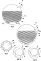
Figure 2 illustrates a sectional view of the heat exchanger taken along line 2-2 ofFigure 1 showing a tube sheet; -
Figure 3 illustrates an enlarged view of a portion ofFigure 2 ; -
Figure 4 illustrates the sectional view ofFigure 2 with refrigerant in the heat exchanger; -
Figure 5 illustrates an enlarged view of a portion ofFigure 4 ; -
Figure 6 illustrates a sectional view taken along line 6-6 ofFigure 2 showing multiple tube sheets; -
Figure 7 illustrates another example tube sheet; -
Figure 8 illustrates yet another example tube sheet; -
Figure 9 illustrates an example locking mechanism for assembling individual body portions; -
Figure 10 illustrates an enlarged view of another example opening in the tube sheet; and -
Figure 11 illustrates the tube sheet ofFigure 10 in an expanded state. -
Figure 1 illustrates anexample heat exchanger 20, such as an evaporator or a condenser, used in a refrigeration system or other device for transferring heat between multiple fluids. Theheat exchanger 20 includes abody portion 22 enclosed by a pair ofend plates 24. A plurality oftubes 28 extend through the enclosure defined by thebody portion 22 and the pair ofend plates 24. Awater box 25 encloses theend plates 24 to provide fluid into or out of the plurality oftubes 28. The plurality oftubes 28 are fluidly sealed with a corresponding one of the pair ofend plates 24 to prevent fluid from leaving theheat exchanger 20 between the plurality oftubes 28 and thecorresponding end plate 24 that thetubes 28 extend through. - Refrigerant enters the
heat exchanger 20 through either afirst port 26A or asecond port 26B and exits theheat exchanger 20 through the other of thefirst port 26A or thesecond port 26B. In the illustrated example, the first andsecond ports heat exchanger 20. Although only a singlefirst port 26A and asingle second port 26B are shown in the illustrated example, there could be multiplefirst ports 26A andsecond ports 26B and thefirst ports 26A and thesecond ports 26B could be located in other portions of theheat exchanger 20, such as the pair ofends plates 24. -
Figure 2 illustrates a sectional view of theheat exchanger 20 taken along line 2-2 ofFigure 1 . As shown inFigure 2 , thebody portion 22 at least partially forms aninternal cavity 30 with the end plates 24 (seeFigure 1 ). In the illustrated example, thebody portion 22 includes a circular cross section. However, thebody portion 22 is not limited to having a circular cross-section and could form other cross-sectional shapes, such as squares, rectangles, or ovals. - The plurality of
tubes 28 are at least partially supported by atube sheet 32. Thetube sheet 32 includes anouter perimeter 32A that at least partially follows aninner contour 22A of thebody portion 22. Thetube sheet 32 could be attached to thebody portion 22 through a mechanical connection, such as a fastener or adhesive, or be friction fit against theinner contour 22A to allow some movement of thetube sheet 32. In the illustrated example, thetube sheet 32 extends between 60% and 70% of a diameter of thebody portion 22 to provide a region of theinternal cavity 30 that is unobstructed by thetube sheet 32. In another example, thetube sheet 32 could extend anywhere from 20% up to 90% of the diameter of the body portion. Additionally, thetube sheet 32 could be located inward from opposing sides ofinner contour 22A of thebody portion 22 such that there is an unobstructed region of theinternal cavity 30 on opposite sides of thetube sheet 32. - The
tube sheet 32 can be made of an expandable material that is formed from a single unitary piece of material. The expandable material includes a material which will swell or expand in the presence of a working fluid, such as a refrigerant. For example, the expandable material expands in the presence of the working fluid by a process that includes at least one of adsorption of molecules of the working fluid onto the expandable material (e.g., onto the wettable surface) or diffusion of the working fluid into the expandable material. The expandable material can include a polymer material, for example, Nylon (e.g.,Nylon 6,6), polytetrafluoroethylene (PTFE), polyimide, polyether ether ketone (PEEK), polyphenylene sulfide (PPS), polyamide-imide (PAI). The expandable material can optionally further include a filler material, for example, glass fiber, carbon fiber, basalt fiber, aramid fiber or the like. The expandable material can include 0 weight % (wt%) to 90 wt% filler material. Thetube sheet 32 can be formed from a single piece of material through either casting the material in a die or machining a sheet of the material to the desired profile to accommodate the plurality oftubes 28 and the shape of theinner contour 22A. The working fluid can include R744 (CO2), R410a, R1234zd, R290 (propane), R1224yd, R1123, R1234ze, or another similar working fluid. - In the illustrated example, the
tube sheet 32 includes a plurality ofopenings 34 that each have a diameter D1. The diameter D1 is larger than an outer diameter DT of each of the plurality of tubes 28 (seeFigure 3 ). The difference in length between the diameter D1 and the diameter DT creates a spacing between the plurality oftubes 28 and a corresponding one of theopenings 34. The spacing formed between the plurality oftubes 28 and the corresponding one of theopenings 34 allows for the plurality oftubes 28 to easily pass through thetube sheet 32 during assembly of theheat exchanger 20. -
Figures 4 and 5 illustrate thetube sheet 32 in an expanded state when exposed to refrigerant. Refrigerant is introduced into theheat exchanger 20 through one of the first andsecond ports heat exchanger 20 through the other of the first andsecond ports heat exchanger 20 through the first andsecond ports - When the
tube sheet 32 is in an expanded state, the diameter D1 of theopenings 34 decreases to close the spacing between theopenings 34 and the outer diameter of the corresponding one of the plurality oftubes 28. This brings thetube sheet 32 into at least partial contact with the plurality oftubes 28 to stabilize the plurality oftubes 28 to prevent damage resulting from vibrations or movement during operation of theheat exchanger 20. Thetube sheet 32 can also includepassages 35 extending through a mid-portion of thetube sheet 32 oredge passages 37 at least partially defined by thetube sheet 32 and thebody portion 22. - Also, the expanding properties of the
tube sheet 32 in response to exposure to refrigerant eliminates the need for additional mechanical attachment between thetube sheet 32 and the plurality oftubes 28. By eliminating the need for additional mechanical attachment betweentube sheet 32 and the plurality oftubes 28, the amount of time required to manufacture theheat exchanger 20 is greatly reduced due to a number of mechanical attachments between the plurality oftubes 28 and thetube sheet 32 and the level of precision needed to make those attachments. - Also, by eliminating the need for mechanical attachments between the
tube sheet 32 and the plurality oftubes 28, such as swaging or using fasteners, the plurality oftubes 28 can includeheat enhancing features 40 over the entire length of thetubes 28. This increases the heat transfer between the refrigerant in theinternal cavity 30 and the fluid passing through thetubes 28. Also, as shown inFigure 5 , thetube sheet 32 has expanded such that the opening 34 contacts thetube 28 to provide support for the tube. -
Figures 10 and 11 illustrate anotherexample opening 34A in thetube sheet 32. Theopening 34A is irregular in shape and includes a plurality of projections. When thetube sheet 32 is placed in contact with refrigerant, thetube sheet 32 expands and contacts the tube 28 (Figure 11 ) to prevent thetube 28 from moving or vibration during operation of theheat exchanger 20. The projections in theopening 34A also allow refrigerant to pass between thetube 28 and thetube sheet 32. -
Figure 6 illustrates a sectional view taken along line 6-6 ofFigure 2 . As shown inFigure 6 , thetube sheets 32 only extend partially across a diameter of theinternal cavity 30 to allow the flow of refrigerant through theheat exchanger 20. In the illustrated example, there are threetube sheets 32 located in theinternal cavity 30 and all three of thetube sheets 32 are all aligned along the same portion of theinternal cavity 30 to allow movement of refrigerant as described above. In another example, thetube sheet 32 could be spaced from opposing sides ofbody portion 22 when the plurality oftubes 28 only extend through a middle portion of theinternal cavity 30. -
Figure 7 illustrates anotherexample tube sheet 132 similar to thetube sheet 32 above except where described above or shown in the Figures. Thetube sheet 132 includesopenings 134 for accepting a corresponding one of the plurality oftubes 28 andreinforcement members 135 extending between theopenings 134 in thetube sheet 132 forming a matrix. Thereinforcement members 135 can be attached to an external surface of thetube sheet 132 to form a support structure or be located within thetube sheet 132 itself. Thereinforcement members 135 can be metallic rods, such as steel or aluminum or thereinforcement members 135 can be fibrous. In the illustrated example, at least one of thereinforcement members 135 extends from a first perimeter location on thetube sheet 132 to a second perimeter location on thetube sheet 132 generally opposite the first perimeter location. -
Figure 8 illustrates yet anotherexample tube sheet 232 similar to thetube sheet 32 above except where described above or shown in Figures. Thetube sheet 32 is comprised of a plurality ofbody portions 235 each having a hexagonal shape and anopening 234 for accepting a corresponding one of the plurality oftubes 28. As shown inFigure 8 , the hexagonal bodies fit together to form atube sheet 232 that closely approximates theinner contour 22A of thebody portion 22. Thebody portions 235 can fit together with a friction fit, an adhesive, or vibration welding technique. In the illustrated example, thebody portions 235 are made of a single unitary piece of refrigerant expanding material. - The
body portions 235 can easily be added or subtracted from thetube sheet 232 to customize thetube sheet 232 for a specific application. This reduces the amount of time needed to manufacture or machine additional tube sheets for low volume applications. Although thebody portions 235 are shown as being hexagons in the illustrated example, other shapes are also contemplated such as triangles, pentagons, hexagons, squares, or rectangles. -
Figure 9 illustrates another exampleindividual body portion 335 similar to thebody portion 235 above except where described below or shown in the Figures. Thebody portion 335 can attach to anadjacent body portion 335 through the use of mountinglegs 337 that are moveable withinchannels 339 in thebody portion 335. Because the mountinglegs 337 are moveable and able to slide into thechannels 339, the mountinglegs 337 can engageadjacent body portions 335 and lock theadjacent body portions 335 together to form a grid similar to the grid shown inFigure 8 . Although thebody portions 335 are shown as being hexagons in the illustrated example, other shapes are also contemplated such as triangles, pentagons, hexagons, squares, or rectangles. - Although the different non-limiting embodiments are illustrated as having specific components, the embodiments of this disclosure are not limited to those particular combinations. It is possible to use some of the components or features from any of the non-limiting embodiments in combination with features or components from any of the other non-limiting embodiments.
- It should be understood that like reference numerals identify corresponding or similar elements throughout the several drawings. It should also be understood that although a particular component arrangement is disclosed and illustrated in these exemplary embodiments, other arrangements could also benefit from the teachings of this disclosure.
- The foregoing description shall be interpreted as illustrative and not in any limiting sense. A worker of ordinary skill in the art would understand that certain modifications could come within the scope of this invention. For these reasons, the following claims should be studied to determine the true scope and content of this invention.
- The following clauses set out aspects of the present disclosure, which may or may not be presently claimed, but which may form basis for future amendments and/or a divisional application:
- 1. A heat exchanger comprising:
- a body portion;
- a pair of end plates at least partially forming an enclosure with the body portion;
- a plurality of tubes extending through at least one of the body portion and the pair of end plates; and
- at least one tube sheet including a plurality of openings with a corresponding one of the plurality of tubes located in one of the plurality of openings, wherein the tube sheet is made of a material which expands in the presence of refrigerant.
- 2. The heat exchanger of clause 1, wherein the heat exchanger is a non-baffled heat exchanger.
- 3. The heat exchanger of
clause 1 or 2, wherein the tube sheet at least partially follows an inner contour of the body portion, optionally wherein the at least one tube sheet extends between 20% and 90% of a diameter of the body portion. - 4. The heat exchanger of
clause 1, 2 or 3, wherein the body portion includes a first refrigerant port and a second refrigerant port and the at least one tube sheet includes a plurality of tube sheets. - 5. The heat exchanger of any preceding clause, further comprising a support structure supporting the at least one tube sheet, optionally wherein the support structure includes a plurality of rods forming a matrix.
- 6. The heat exchanger of any preceding clause, wherein the tube sheet is formed of a single unitary piece of material.
- 7. The heat exchanger of
clause 6, wherein the at least one tube sheet includes refrigerant expanding material extending uninterrupted between adjacent openings of the plurality of openings. - 8. The heat exchanger of any of clauses 1 to 5, wherein the at least one tube sheet is formed from a plurality of geometric shaped members and each of the plurality of geometric shaped members includes one of the plurality of openings and each of the plurality of geometric shaped members are made of a single unitary piece of material.
- 9. The heat exchanger of any preceding clause, wherein the plurality of tubes include heat transfer enhancing features on an exterior surface that engage the at least one tube sheet.
- 10. A method of operating a heat exchanger comprising the steps of:
- supporting a plurality of tubes extending through a corresponding one of a plurality of opening in a tube sheet; and
- placing the tube sheet in contact with a refrigerant, wherein the tube sheet expands in response to contact with the refrigerant entering the heat exchanger and contacts the plurality of tubes.
- 11. The method of clause 10, wherein the plurality of tubes include heat transfer enhancing features on an exterior surface that engage the tube sheet, and/or wherein the tube sheet extends between 20% and 90% of a diameter of a body portion of the heat exchanger.
- 12. The method of clause 10 or 11, further comprising a support structure supporting the tube sheet, and/or further comprising reducing vibrations and movement of the plurality of tubes with the tube sheet in contact with the refrigerant.
- 13. The method of clause 10, 11 or 12, wherein the heat exchanger is a non-baffled heat exchanger.
- 14. The method of any of clauses 10 to 13, wherein the plurality of tubes sheets are made of a single unitary piece of refrigerant expanding material.
- 15. The method of any of clauses 10 to 13, wherein the tube sheet includes a plurality of geometric shapes assembled together to form the tube sheet.
Claims (15)
- A heat exchanger (20) comprising:a body portion (22);a pair of end plates (24) at least partially forming an enclosure with the body portion;a plurality of tubes (28) extending through at least one of the body portion and the pair of end plates; andat least one tube sheet (232) including a plurality of openings (234) with a corresponding one of the plurality of tubes located in one of the plurality of openings, wherein the tube sheet is made of a material which expands in the presence of refrigerant,characterized in that the at least one tube sheet (232) is formed from a plurality of geometric shaped members (235; 335) and each of the plurality of geometric shaped members includes one of the plurality of openings (234) and each of the plurality of geometric shaped members are made of a single unitary piece of material.
- The heat exchanger (20) of claim 1, wherein the plurality of geometric shaped members (235; 335) fit together to form the tube sheet (232).
- The heat exchanger (20) of claim 1 or 2, wherein the plurality of geometric shaped members (235) are fitted together with a friction fit, an adhesive, or vibration welding technique.
- The heat exchanger of claim 1 or 2, wherein each geometric shaped member (335) comprises a plurality of channels (339), wherein the channels (339) are configured to receive a mounting leg (337) which is moveable and able to slide within the channel (339), and adjacent geometric shaped members (335) can be locked together by engaging a mounting leg (337) in a respective channel (339) in respective adjacent geometric shaped members (335).
- The heat exchanger (20) of any preceding claim, wherein the heat exchanger is a non-baffled heat exchanger.
- The heat exchanger (20) of any preceding claim, wherein the tube sheet (232) at least partially follows an inner contour (22A) of the body portion (22), optionally wherein the at least one tube sheet (232) extends between 20% and 90% of a diameter of the body portion.
- The heat exchanger (20) of any preceding claim, wherein the body portion (22) includes a first refrigerant port (26A) and a second refrigerant port (26B) and the at least one tube sheet (232) includes a plurality of tube sheets.
- The heat exchanger (20) of any preceding claim, further comprising a support structure supporting the at least one tube sheet (232), optionally wherein the support structure includes a plurality of rods forming a matrix.
- The heat exchanger (20) of any preceding claim, wherein the plurality of tubes (28) include heat transfer enhancing features on an exterior surface that engage the at least one tube sheet (232).
- A method of operating a heat exchanger (20) comprising the steps of:supporting a plurality of tubes (28) extending through a corresponding one of a plurality of opening (234) in a tube sheet (232); andplacing the tube sheet in contact with a refrigerant, wherein the tube sheet expands in response to contact with the refrigerant entering the heat exchanger and contacts the plurality of tubes (28),characterized in that the tube sheet (232) includes a plurality of geometric shapes (235; 335) assembled together to form the tube sheet.
- The method of claim 10, wherein the plurality of geometric shaped members (235) are fitted together with a friction fit, an adhesive, or vibration welding technique.
- The method of claim 10, wherein each geometric shaped member (335) comprises a plurality of channels (339), wherein the channels (339) are configured to receive a mounting leg (337) which is moveable and able to slide within the channel (339), and adjacent geometric shaped members (335) are locked together by engaging a mounting leg (337) in a respective channel (339) in respective adjacent geometric shaped members (335).
- The method of any of claims 9 to 12, wherein the plurality of tubes (28) include heat transfer enhancing features on an exterior surface that engage the tube sheet (232), and/or wherein the tube sheet (232) extends between 20% and 90% of a diameter of a body portion (22) of the heat exchanger (20).
- The method of any of claims 9 to 13, further comprising a support structure supporting the tube sheet (232), and/or further comprising reducing vibrations and movement of the plurality of tubes (28) with the tube sheet (232) in contact with the refrigerant.
- The method of any of claims 9 to 14 , wherein the heat exchanger (20) is a non-baffled heat exchanger.
Applications Claiming Priority (2)
| Application Number | Priority Date | Filing Date | Title |
|---|---|---|---|
| US201962818426P | 2019-03-14 | 2019-03-14 | |
| EP20161221.5A EP3708939B1 (en) | 2019-03-14 | 2020-03-05 | Heat exchanger and associated tube sheet |
Related Parent Applications (1)
| Application Number | Title | Priority Date | Filing Date |
|---|---|---|---|
| EP20161221.5A Division EP3708939B1 (en) | 2019-03-14 | 2020-03-05 | Heat exchanger and associated tube sheet |
Publications (2)
| Publication Number | Publication Date |
|---|---|
| EP3951304A1 true EP3951304A1 (en) | 2022-02-09 |
| EP3951304B1 EP3951304B1 (en) | 2024-09-11 |
Family
ID=69779840
Family Applications (2)
| Application Number | Title | Priority Date | Filing Date |
|---|---|---|---|
| EP20161221.5A Active EP3708939B1 (en) | 2019-03-14 | 2020-03-05 | Heat exchanger and associated tube sheet |
| EP21195797.2A Active EP3951304B1 (en) | 2019-03-14 | 2020-03-05 | Heat exchanger and associated tube sheet |
Family Applications Before (1)
| Application Number | Title | Priority Date | Filing Date |
|---|---|---|---|
| EP20161221.5A Active EP3708939B1 (en) | 2019-03-14 | 2020-03-05 | Heat exchanger and associated tube sheet |
Country Status (4)
| Country | Link |
|---|---|
| US (1) | US11656036B2 (en) |
| EP (2) | EP3708939B1 (en) |
| CN (1) | CN111692901A (en) |
| ES (1) | ES2899102T3 (en) |
Families Citing this family (1)
| Publication number | Priority date | Publication date | Assignee | Title |
|---|---|---|---|---|
| US12292242B2 (en) * | 2022-05-26 | 2025-05-06 | Hamilton Sundstrand Corporation | Surface texture enhanced glass-ceramic matrix composite heat exchanger |
Citations (6)
| Publication number | Priority date | Publication date | Assignee | Title |
|---|---|---|---|---|
| US3324941A (en) * | 1964-01-02 | 1967-06-13 | Carrier Corp | Heat exchanger with expansible tube seal |
| US3332479A (en) * | 1964-01-02 | 1967-07-25 | Carrier Corp | Heat exchanger with expansible tube seal |
| US4643249A (en) * | 1982-11-22 | 1987-02-17 | Caterpillar Inc. | Heat exchanger baffle plate |
| US5036912A (en) * | 1989-03-28 | 1991-08-06 | Btr Industries Limited | Heat exchanger |
| US20160273845A1 (en) * | 2013-12-18 | 2016-09-22 | Casale Sa | Tube heat exchange unit for internals of heat exchangers reactors |
| US20180283813A1 (en) * | 2017-03-28 | 2018-10-04 | Uop Llc | Wet-cooled heat exchanger |
Family Cites Families (14)
| Publication number | Priority date | Publication date | Assignee | Title |
|---|---|---|---|---|
| US2876975A (en) * | 1957-10-28 | 1959-03-10 | Aluminum Co Of America | Tube supporting means for fluidized heat exchange apparatus |
| US3311164A (en) | 1964-01-02 | 1967-03-28 | Carrier Corp | Heat exchanger with expansible tube seal |
| DE1501620A1 (en) * | 1964-04-09 | 1969-06-26 | Grenobloise Etude Appl | Improvements from heat exchangers |
| US3321013A (en) | 1965-07-12 | 1967-05-23 | Frick Co | Shell and tube heat exchanger |
| GB9820712D0 (en) * | 1998-09-24 | 1998-11-18 | Btr Industries Ltd | Heat exchanger |
| US6516627B2 (en) * | 2001-05-04 | 2003-02-11 | American Standard International Inc. | Flowing pool shell and tube evaporator |
| JP2005221118A (en) * | 2004-02-04 | 2005-08-18 | Japan Steel Works Ltd:The | Multi-tube heat exchanger |
| US6868695B1 (en) * | 2004-04-13 | 2005-03-22 | American Standard International Inc. | Flow distributor and baffle system for a falling film evaporator |
| US8365812B2 (en) * | 2007-06-27 | 2013-02-05 | King Fahd University Of Petroleum And Minerals | Shell and tube heat exchanger |
| EP2232166B1 (en) * | 2008-01-11 | 2012-04-18 | Johnson Controls Technology Company | Vapor compression system |
| US8517086B2 (en) * | 2008-02-29 | 2013-08-27 | Caterpillar Inc. | Composite heat exchanger end structure |
| US8276653B2 (en) * | 2008-03-28 | 2012-10-02 | Saudi Arabian Oil Company | Raised overlapped impingement plate |
| WO2014165826A1 (en) * | 2013-04-04 | 2014-10-09 | Brentwood Industries, Inc. | Polymeric coil assembly and method of making the same |
| CN205642116U (en) * | 2016-01-29 | 2016-10-12 | 一铁(北京)金属制品有限公司 | Fluoroplastics pipe heat exchanger tube and tube plate's connection, seal structure |
-
2020
- 2020-02-05 US US16/782,385 patent/US11656036B2/en active Active
- 2020-03-05 ES ES20161221T patent/ES2899102T3/en active Active
- 2020-03-05 EP EP20161221.5A patent/EP3708939B1/en active Active
- 2020-03-05 EP EP21195797.2A patent/EP3951304B1/en active Active
- 2020-03-13 CN CN202010174593.9A patent/CN111692901A/en active Pending
Patent Citations (6)
| Publication number | Priority date | Publication date | Assignee | Title |
|---|---|---|---|---|
| US3324941A (en) * | 1964-01-02 | 1967-06-13 | Carrier Corp | Heat exchanger with expansible tube seal |
| US3332479A (en) * | 1964-01-02 | 1967-07-25 | Carrier Corp | Heat exchanger with expansible tube seal |
| US4643249A (en) * | 1982-11-22 | 1987-02-17 | Caterpillar Inc. | Heat exchanger baffle plate |
| US5036912A (en) * | 1989-03-28 | 1991-08-06 | Btr Industries Limited | Heat exchanger |
| US20160273845A1 (en) * | 2013-12-18 | 2016-09-22 | Casale Sa | Tube heat exchange unit for internals of heat exchangers reactors |
| US20180283813A1 (en) * | 2017-03-28 | 2018-10-04 | Uop Llc | Wet-cooled heat exchanger |
Also Published As
| Publication number | Publication date |
|---|---|
| ES2899102T3 (en) | 2022-03-10 |
| CN111692901A (en) | 2020-09-22 |
| US11656036B2 (en) | 2023-05-23 |
| US20200292250A1 (en) | 2020-09-17 |
| EP3951304B1 (en) | 2024-09-11 |
| EP3708939A1 (en) | 2020-09-16 |
| EP3708939B1 (en) | 2021-10-13 |
Similar Documents
| Publication | Publication Date | Title |
|---|---|---|
| EP0607006B1 (en) | Plate fin heat exchanger built-in type multi-stage thermosiphon | |
| EP2610571B1 (en) | Heat exchanger assembly having a distributor tube retainer tab | |
| EP3926258A1 (en) | Distributor and heat exchanger | |
| JP2007247891A (en) | Piping joint device, piping joint structure of heat exchanger and piping method of heat exchanger | |
| US12085214B2 (en) | Vacuum adiabatic body and refrigerator | |
| EP3951304B1 (en) | Heat exchanger and associated tube sheet | |
| KR20170067351A (en) | Heat exchanger | |
| EP1373809B1 (en) | Apparatus and method for discharging vapour and liquid | |
| US20150285567A1 (en) | Flat heat transfer tube, manufacturing method of cross fin tube type heat exchanger having the same, and cross fin tube type heat exchanger manufactured by the same manufacturing method | |
| EP1046875B1 (en) | Finned pack heat exchanger provided with side stiffening and reinforcing section members for refrigerating, conditioning and heating apparatus | |
| CN116734652A (en) | Non-metallic partitions for heat exchangers | |
| KR20130101282A (en) | Shell and plate heat exchanger | |
| US20240085056A1 (en) | Window type air-conditioner and installation method thereof | |
| US11629898B2 (en) | HVAC condenser coil isolators | |
| KR20090001455U (en) | Air Conditioner with Vibration Reduction Device | |
| KR101210570B1 (en) | Heat exchanger | |
| WO2024040917A1 (en) | Base plate assembly for air conditioner, air conditioner, and recreational vehicle | |
| JP2014194295A (en) | Air conditioner | |
| US20180149432A1 (en) | Heat exchanger with liquid receiver | |
| CN118342239A (en) | Method for manufacturing heat exchanger | |
| EP2313729A1 (en) | Compact finned heat exchanger | |
| CN222597008U (en) | Pipe compression device, pipeline structure and air conditioner | |
| KR102725038B1 (en) | Heat exchanger and refrigeration cycle device | |
| CN222993216U (en) | Refrigerating system and cold drink machine | |
| US20240183621A1 (en) | Heat pipe |
Legal Events
| Date | Code | Title | Description |
|---|---|---|---|
| PUAI | Public reference made under article 153(3) epc to a published international application that has entered the european phase |
Free format text: ORIGINAL CODE: 0009012 |
|
| STAA | Information on the status of an ep patent application or granted ep patent |
Free format text: STATUS: THE APPLICATION HAS BEEN PUBLISHED |
|
| AC | Divisional application: reference to earlier application |
Ref document number: 3708939 Country of ref document: EP Kind code of ref document: P |
|
| AK | Designated contracting states |
Kind code of ref document: A1 Designated state(s): AL AT BE BG CH CY CZ DE DK EE ES FI FR GB GR HR HU IE IS IT LI LT LU LV MC MK MT NL NO PL PT RO RS SE SI SK SM TR |
|
| STAA | Information on the status of an ep patent application or granted ep patent |
Free format text: STATUS: REQUEST FOR EXAMINATION WAS MADE |
|
| 17P | Request for examination filed |
Effective date: 20220722 |
|
| RBV | Designated contracting states (corrected) |
Designated state(s): AL AT BE BG CH CY CZ DE DK EE ES FI FR GB GR HR HU IE IS IT LI LT LU LV MC MK MT NL NO PL PT RO RS SE SI SK SM TR |
|
| GRAP | Despatch of communication of intention to grant a patent |
Free format text: ORIGINAL CODE: EPIDOSNIGR1 |
|
| STAA | Information on the status of an ep patent application or granted ep patent |
Free format text: STATUS: GRANT OF PATENT IS INTENDED |
|
| RIC1 | Information provided on ipc code assigned before grant |
Ipc: F28D 7/16 20060101AFI20240319BHEP |
|
| INTG | Intention to grant announced |
Effective date: 20240410 |
|
| GRAS | Grant fee paid |
Free format text: ORIGINAL CODE: EPIDOSNIGR3 |
|
| GRAA | (expected) grant |
Free format text: ORIGINAL CODE: 0009210 |
|
| STAA | Information on the status of an ep patent application or granted ep patent |
Free format text: STATUS: THE PATENT HAS BEEN GRANTED |
|
| AC | Divisional application: reference to earlier application |
Ref document number: 3708939 Country of ref document: EP Kind code of ref document: P |
|
| AK | Designated contracting states |
Kind code of ref document: B1 Designated state(s): AL AT BE BG CH CY CZ DE DK EE ES FI FR GB GR HR HU IE IS IT LI LT LU LV MC MK MT NL NO PL PT RO RS SE SI SK SM TR |
|
| REG | Reference to a national code |
Ref country code: GB Ref legal event code: FG4D |
|
| REG | Reference to a national code |
Ref country code: CH Ref legal event code: EP |
|
| REG | Reference to a national code |
Ref country code: DE Ref legal event code: R096 Ref document number: 602020037756 Country of ref document: DE |
|
| REG | Reference to a national code |
Ref country code: IE Ref legal event code: FG4D |
|
| REG | Reference to a national code |
Ref country code: LT Ref legal event code: MG9D |
|
| PG25 | Lapsed in a contracting state [announced via postgrant information from national office to epo] |
Ref country code: NO Free format text: LAPSE BECAUSE OF FAILURE TO SUBMIT A TRANSLATION OF THE DESCRIPTION OR TO PAY THE FEE WITHIN THE PRESCRIBED TIME-LIMIT Effective date: 20241211 |
|
| REG | Reference to a national code |
Ref country code: NL Ref legal event code: MP Effective date: 20240911 |
|
| PG25 | Lapsed in a contracting state [announced via postgrant information from national office to epo] |
Ref country code: GR Free format text: LAPSE BECAUSE OF FAILURE TO SUBMIT A TRANSLATION OF THE DESCRIPTION OR TO PAY THE FEE WITHIN THE PRESCRIBED TIME-LIMIT Effective date: 20241212 Ref country code: FI Free format text: LAPSE BECAUSE OF FAILURE TO SUBMIT A TRANSLATION OF THE DESCRIPTION OR TO PAY THE FEE WITHIN THE PRESCRIBED TIME-LIMIT Effective date: 20240911 |
|
| PG25 | Lapsed in a contracting state [announced via postgrant information from national office to epo] |
Ref country code: BG Free format text: LAPSE BECAUSE OF FAILURE TO SUBMIT A TRANSLATION OF THE DESCRIPTION OR TO PAY THE FEE WITHIN THE PRESCRIBED TIME-LIMIT Effective date: 20240911 |
|
| PG25 | Lapsed in a contracting state [announced via postgrant information from national office to epo] |
Ref country code: LV Free format text: LAPSE BECAUSE OF FAILURE TO SUBMIT A TRANSLATION OF THE DESCRIPTION OR TO PAY THE FEE WITHIN THE PRESCRIBED TIME-LIMIT Effective date: 20240911 |
|
| PG25 | Lapsed in a contracting state [announced via postgrant information from national office to epo] |
Ref country code: HR Free format text: LAPSE BECAUSE OF FAILURE TO SUBMIT A TRANSLATION OF THE DESCRIPTION OR TO PAY THE FEE WITHIN THE PRESCRIBED TIME-LIMIT Effective date: 20240911 |
|
| PG25 | Lapsed in a contracting state [announced via postgrant information from national office to epo] |
Ref country code: ES Free format text: LAPSE BECAUSE OF FAILURE TO SUBMIT A TRANSLATION OF THE DESCRIPTION OR TO PAY THE FEE WITHIN THE PRESCRIBED TIME-LIMIT Effective date: 20240911 Ref country code: RS Free format text: LAPSE BECAUSE OF FAILURE TO SUBMIT A TRANSLATION OF THE DESCRIPTION OR TO PAY THE FEE WITHIN THE PRESCRIBED TIME-LIMIT Effective date: 20241211 |
|
| PG25 | Lapsed in a contracting state [announced via postgrant information from national office to epo] |
Ref country code: RS Free format text: LAPSE BECAUSE OF FAILURE TO SUBMIT A TRANSLATION OF THE DESCRIPTION OR TO PAY THE FEE WITHIN THE PRESCRIBED TIME-LIMIT Effective date: 20241211 Ref country code: NO Free format text: LAPSE BECAUSE OF FAILURE TO SUBMIT A TRANSLATION OF THE DESCRIPTION OR TO PAY THE FEE WITHIN THE PRESCRIBED TIME-LIMIT Effective date: 20241211 Ref country code: LV Free format text: LAPSE BECAUSE OF FAILURE TO SUBMIT A TRANSLATION OF THE DESCRIPTION OR TO PAY THE FEE WITHIN THE PRESCRIBED TIME-LIMIT Effective date: 20240911 Ref country code: HR Free format text: LAPSE BECAUSE OF FAILURE TO SUBMIT A TRANSLATION OF THE DESCRIPTION OR TO PAY THE FEE WITHIN THE PRESCRIBED TIME-LIMIT Effective date: 20240911 Ref country code: GR Free format text: LAPSE BECAUSE OF FAILURE TO SUBMIT A TRANSLATION OF THE DESCRIPTION OR TO PAY THE FEE WITHIN THE PRESCRIBED TIME-LIMIT Effective date: 20241212 Ref country code: FI Free format text: LAPSE BECAUSE OF FAILURE TO SUBMIT A TRANSLATION OF THE DESCRIPTION OR TO PAY THE FEE WITHIN THE PRESCRIBED TIME-LIMIT Effective date: 20240911 Ref country code: ES Free format text: LAPSE BECAUSE OF FAILURE TO SUBMIT A TRANSLATION OF THE DESCRIPTION OR TO PAY THE FEE WITHIN THE PRESCRIBED TIME-LIMIT Effective date: 20240911 Ref country code: BG Free format text: LAPSE BECAUSE OF FAILURE TO SUBMIT A TRANSLATION OF THE DESCRIPTION OR TO PAY THE FEE WITHIN THE PRESCRIBED TIME-LIMIT Effective date: 20240911 |
|
| REG | Reference to a national code |
Ref country code: AT Ref legal event code: MK05 Ref document number: 1723041 Country of ref document: AT Kind code of ref document: T Effective date: 20240911 |
|
| PG25 | Lapsed in a contracting state [announced via postgrant information from national office to epo] |
Ref country code: NL Free format text: LAPSE BECAUSE OF FAILURE TO SUBMIT A TRANSLATION OF THE DESCRIPTION OR TO PAY THE FEE WITHIN THE PRESCRIBED TIME-LIMIT Effective date: 20240911 |
|
| PG25 | Lapsed in a contracting state [announced via postgrant information from national office to epo] |
Ref country code: PT Free format text: LAPSE BECAUSE OF FAILURE TO SUBMIT A TRANSLATION OF THE DESCRIPTION OR TO PAY THE FEE WITHIN THE PRESCRIBED TIME-LIMIT Effective date: 20250113 Ref country code: IS Free format text: LAPSE BECAUSE OF FAILURE TO SUBMIT A TRANSLATION OF THE DESCRIPTION OR TO PAY THE FEE WITHIN THE PRESCRIBED TIME-LIMIT Effective date: 20250111 |
|
| PGFP | Annual fee paid to national office [announced via postgrant information from national office to epo] |
Ref country code: DE Payment date: 20250218 Year of fee payment: 6 |
|
| PG25 | Lapsed in a contracting state [announced via postgrant information from national office to epo] |
Ref country code: RO Free format text: LAPSE BECAUSE OF FAILURE TO SUBMIT A TRANSLATION OF THE DESCRIPTION OR TO PAY THE FEE WITHIN THE PRESCRIBED TIME-LIMIT Effective date: 20240911 Ref country code: SM Free format text: LAPSE BECAUSE OF FAILURE TO SUBMIT A TRANSLATION OF THE DESCRIPTION OR TO PAY THE FEE WITHIN THE PRESCRIBED TIME-LIMIT Effective date: 20240911 |
|
| PG25 | Lapsed in a contracting state [announced via postgrant information from national office to epo] |
Ref country code: AT Free format text: LAPSE BECAUSE OF FAILURE TO SUBMIT A TRANSLATION OF THE DESCRIPTION OR TO PAY THE FEE WITHIN THE PRESCRIBED TIME-LIMIT Effective date: 20240911 Ref country code: EE Free format text: LAPSE BECAUSE OF FAILURE TO SUBMIT A TRANSLATION OF THE DESCRIPTION OR TO PAY THE FEE WITHIN THE PRESCRIBED TIME-LIMIT Effective date: 20240911 |
|
| PG25 | Lapsed in a contracting state [announced via postgrant information from national office to epo] |
Ref country code: PL Free format text: LAPSE BECAUSE OF FAILURE TO SUBMIT A TRANSLATION OF THE DESCRIPTION OR TO PAY THE FEE WITHIN THE PRESCRIBED TIME-LIMIT Effective date: 20240911 Ref country code: CZ Free format text: LAPSE BECAUSE OF FAILURE TO SUBMIT A TRANSLATION OF THE DESCRIPTION OR TO PAY THE FEE WITHIN THE PRESCRIBED TIME-LIMIT Effective date: 20240911 |
|
| PGFP | Annual fee paid to national office [announced via postgrant information from national office to epo] |
Ref country code: FR Payment date: 20250218 Year of fee payment: 6 |
|
| PG25 | Lapsed in a contracting state [announced via postgrant information from national office to epo] |
Ref country code: SK Free format text: LAPSE BECAUSE OF FAILURE TO SUBMIT A TRANSLATION OF THE DESCRIPTION OR TO PAY THE FEE WITHIN THE PRESCRIBED TIME-LIMIT Effective date: 20240911 Ref country code: IT Free format text: LAPSE BECAUSE OF FAILURE TO SUBMIT A TRANSLATION OF THE DESCRIPTION OR TO PAY THE FEE WITHIN THE PRESCRIBED TIME-LIMIT Effective date: 20240911 |
|
| REG | Reference to a national code |
Ref country code: DE Ref legal event code: R097 Ref document number: 602020037756 Country of ref document: DE |
|
| PG25 | Lapsed in a contracting state [announced via postgrant information from national office to epo] |
Ref country code: DK Free format text: LAPSE BECAUSE OF FAILURE TO SUBMIT A TRANSLATION OF THE DESCRIPTION OR TO PAY THE FEE WITHIN THE PRESCRIBED TIME-LIMIT Effective date: 20240911 |
|
| PLBE | No opposition filed within time limit |
Free format text: ORIGINAL CODE: 0009261 |
|
| STAA | Information on the status of an ep patent application or granted ep patent |
Free format text: STATUS: NO OPPOSITION FILED WITHIN TIME LIMIT |
|
| 26N | No opposition filed |
Effective date: 20250612 |
|
| PG25 | Lapsed in a contracting state [announced via postgrant information from national office to epo] |
Ref country code: SE Free format text: LAPSE BECAUSE OF FAILURE TO SUBMIT A TRANSLATION OF THE DESCRIPTION OR TO PAY THE FEE WITHIN THE PRESCRIBED TIME-LIMIT Effective date: 20240911 |
|
| PG25 | Lapsed in a contracting state [announced via postgrant information from national office to epo] |
Ref country code: MC Free format text: LAPSE BECAUSE OF FAILURE TO SUBMIT A TRANSLATION OF THE DESCRIPTION OR TO PAY THE FEE WITHIN THE PRESCRIBED TIME-LIMIT Effective date: 20240911 |
|
| REG | Reference to a national code |
Ref country code: CH Ref legal event code: H13 Free format text: ST27 STATUS EVENT CODE: U-0-0-H10-H13 (AS PROVIDED BY THE NATIONAL OFFICE) Effective date: 20251023 |
|
| PG25 | Lapsed in a contracting state [announced via postgrant information from national office to epo] |
Ref country code: LU Free format text: LAPSE BECAUSE OF NON-PAYMENT OF DUE FEES Effective date: 20250305 |
|
| GBPC | Gb: european patent ceased through non-payment of renewal fee |
Effective date: 20250305 |
|
| REG | Reference to a national code |
Ref country code: BE Ref legal event code: MM Effective date: 20250331 |
|
| PG25 | Lapsed in a contracting state [announced via postgrant information from national office to epo] |
Ref country code: GB Free format text: LAPSE BECAUSE OF NON-PAYMENT OF DUE FEES Effective date: 20250305 |
|
| PG25 | Lapsed in a contracting state [announced via postgrant information from national office to epo] |
Ref country code: BE Free format text: LAPSE BECAUSE OF NON-PAYMENT OF DUE FEES Effective date: 20250331 |
|
| PG25 | Lapsed in a contracting state [announced via postgrant information from national office to epo] |
Ref country code: CH Free format text: LAPSE BECAUSE OF NON-PAYMENT OF DUE FEES Effective date: 20250331 |
|
| PG25 | Lapsed in a contracting state [announced via postgrant information from national office to epo] |
Ref country code: IE Free format text: LAPSE BECAUSE OF NON-PAYMENT OF DUE FEES Effective date: 20250305 |