EP3951281A1 - Air-conditioner indoor unit and method for installing air-conditioner indoor unit - Google Patents
Air-conditioner indoor unit and method for installing air-conditioner indoor unit Download PDFInfo
- Publication number
- EP3951281A1 EP3951281A1 EP20783874.9A EP20783874A EP3951281A1 EP 3951281 A1 EP3951281 A1 EP 3951281A1 EP 20783874 A EP20783874 A EP 20783874A EP 3951281 A1 EP3951281 A1 EP 3951281A1
- Authority
- EP
- European Patent Office
- Prior art keywords
- indoor unit
- housing
- air
- propeller fan
- fan
- Prior art date
- Legal status (The legal status is an assumption and is not a legal conclusion. Google has not performed a legal analysis and makes no representation as to the accuracy of the status listed.)
- Pending
Links
Images


Classifications
-
- F—MECHANICAL ENGINEERING; LIGHTING; HEATING; WEAPONS; BLASTING
- F24—HEATING; RANGES; VENTILATING
- F24F—AIR-CONDITIONING; AIR-HUMIDIFICATION; VENTILATION; USE OF AIR CURRENTS FOR SCREENING
- F24F1/00—Room units for air-conditioning, e.g. separate or self-contained units or units receiving primary air from a central station
- F24F1/0007—Indoor units, e.g. fan coil units
- F24F1/0018—Indoor units, e.g. fan coil units characterised by fans
- F24F1/0029—Axial fans
-
- F—MECHANICAL ENGINEERING; LIGHTING; HEATING; WEAPONS; BLASTING
- F24—HEATING; RANGES; VENTILATING
- F24F—AIR-CONDITIONING; AIR-HUMIDIFICATION; VENTILATION; USE OF AIR CURRENTS FOR SCREENING
- F24F1/00—Room units for air-conditioning, e.g. separate or self-contained units or units receiving primary air from a central station
- F24F1/0007—Indoor units, e.g. fan coil units
- F24F1/0043—Indoor units, e.g. fan coil units characterised by mounting arrangements
- F24F1/0047—Indoor units, e.g. fan coil units characterised by mounting arrangements mounted in the ceiling or at the ceiling
-
- F—MECHANICAL ENGINEERING; LIGHTING; HEATING; WEAPONS; BLASTING
- F24—HEATING; RANGES; VENTILATING
- F24F—AIR-CONDITIONING; AIR-HUMIDIFICATION; VENTILATION; USE OF AIR CURRENTS FOR SCREENING
- F24F13/00—Details common to, or for air-conditioning, air-humidification, ventilation or use of air currents for screening
- F24F13/08—Air-flow control members, e.g. louvres, grilles, flaps or guide plates
- F24F13/082—Grilles, registers or guards
-
- F—MECHANICAL ENGINEERING; LIGHTING; HEATING; WEAPONS; BLASTING
- F24—HEATING; RANGES; VENTILATING
- F24F—AIR-CONDITIONING; AIR-HUMIDIFICATION; VENTILATION; USE OF AIR CURRENTS FOR SCREENING
- F24F13/00—Details common to, or for air-conditioning, air-humidification, ventilation or use of air currents for screening
- F24F13/20—Casings or covers
Definitions
- Embodiments of the present invention relates to an indoor unit of an air conditioner and a method for installing the indoor unit of the air conditioner.
- a known indoor unit of an air conditioner performs air-conditioning in attic space and supplies the conditioned air into the room.
- Such indoor unit includes a casing, a fan, and a heat exchanger.
- the casing has an inlet provided on its side face and an outlet provided on its bottom face.
- the fan is disposed inside the casing, and generates an air flow from the inlet to the outlet.
- the heat exchanger is disposed inside the casing and between the fan and the inlet.
- the conventional indoor unit is installed in the attic space.
- the conventional indoor unit is embedded in a place sufficiently distant from the floor surface of the installation location in the height direction, i.e., embedded in the ceiling.
- the conventional indoor unit is provided with an outlet that has a plurality of round cone-shaped blades, i.e., a so-called anemostat type diffuser.
- This type of outlet blocks the view from directly below.
- it is difficult to directly see the fan in the casing from below the outlet.
- the indoor unit installed to be suspended from the ceiling of the installation location is closer to the floor surface than the conventional type of indoor unit embedded in the ceiling is.
- the commercial value of indoor unit may be reduced due to unnecessary fear of the rotating fan.
- the present invention aims to provide an indoor unit of an air-conditioner, which indoor unit can be installed to be suspended from the ceiling and includes a fan guard allowing the fan rotating in the casing to be readily seen through while providing a sense of security without inciting unnecessary fear of the rotating fan.
- the present invention also aims to provide a method for installing such indoor unit.
- an aspect of the present invention provides an indoor unit of an air-conditioner including: a housing that has an inlet on a side face and an outlet on a bottom face, and can be installed to be suspended from a structure of an installation location; a heat exchanger that is provided inside the housing, faces the inlet, and is annularly disposed in a bottom view of the housing; a propeller fan, which has a rotating shaft extending in a vertical direction of the housing and a plurality of blades radially arranged in a circumferential direction of the rotating shaft, and is surrounded by the heat exchanger in the bottom view of the housing, that sucks in air from the inlet, and blows out air after heat-exchange using the heat exchanger from the outlet toward a lower side of the housing; and a fan guard that is provided at the outlet.
- a projection region of movement range of the plurality of blades being moved by rotation of the propeller fan is defined a first projection area
- a projection area of an opening portion of the fan guard on the virtual plane and inside the projection region is defined as a second projection area
- an opening ratio calculated by dividing the second projection area by the first projection area is 1/2 or more, and is substantially uniform in a rotation direction of the propeller fan.
- the propeller fan has a low-brightness appearance.
- brightness represented by Munsell value of the propeller fan is 5 or less.
- chroma represented by Munsell value of the propeller fan is 4 or less.
- a color of a portion of the indoor unit that can be seen through from below is substantially the same as a color of the propeller fan.
- the heat exchanger has a blackish or bluish appearance.
- a heat insulating material is provided on at least one of a top face of the housing and an opening edge of the outlet, and has a blackish or grayish appearance.
- brightness of appearance of the indoor unit is higher than brightness of the propeller fan.
- a method for installing an indoor unit of an air-conditioner is to install the indoor unit of the air-conditioner above a lighting device at an installation location.
- the present invention can provide an indoor unit of an air-conditioner, which indoor unit can be installed to be suspended from the ceiling and has a fan guard allowing the fan rotating in the casing to be readily seen through while providing a sense of security without inciting unnecessary fear of the rotating fan.
- the present invention can also provide a method for installing the above-described indoor unit.
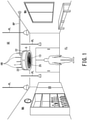
- Fig. 1 is a diagram illustrating an installation location where the indoor unit according to one embodiment of the present invention is installed.
- the air conditioner includes an outdoor unit (not shown) installed outdoors, and an indoor unit 1 installed indoors.
- the outdoor unit and the indoor unit 1 are connected via a refrigerant pipe RP that circulates a refrigerant.
- the refrigeration cycle of the air conditioner circulates the refrigerant between the outdoor unit and the indoor unit 1.
- the indoor unit 1 conditions air in the room, i.e., in the installation location.
- the installation location is surrounded with a floor FL, a wall WA, and a ceiling SE.
- the indoor unit 1 is suspended from a structure at the installation location, specifically, from the ceiling SE or from beams (not shown).
- the ceiling SE of the installation location is provided with a metal rod-shaped hanging members HB extending in the direction toward the floor surface.
- the indoor unit 1 is suspended from the ceiling SE via the hanging members HB. That is, the indoor unit 1 is provided at a position lower than the ceiling SE.
- the indoor unit 1 is a bare unit away from the ceiling SE and disposed indoors in an exposed state without its housing 5 being embedded in the ceiling SE.
- the indoor unit 1 is installed above the pendant light PL of the installation location. More precisely, the indoor unit 1 is installed such that the bottom face of the indoor unit 1 (i.e., a face having an outlet 25 of the indoor unit 1 described below) is located above the light source of the pendant light PL. In this case, the indoor unit 1 may be installed above the pendant light PL by moving the fixing portion between the hanging members HB and the indoor unit 1 up or down. Also in this case, the installation height of the indoor unit 1 may be determined in advance, and then the installation height of the pendant light PL (i.e., hanging position) may be adjusted.
- the installation height of the pendant light PL i.e., hanging position
- the indoor unit 1 includes: the housing 5 that is cylindrical or disc-shaped, and has a circular top face and a circular bottom face; a heat exchanger 6 that is provided inside the housing 5, and is annularly disposed in a bottom view of the housing 5; a fan motor 11 that has a rotating shaft 7 extending in the vertical direction at approximately the center of the housing 5; a propeller fan 9 that has a plurality of blades 8 radially arranged in the circumferential direction of the rotating shaft 7, and is surrounded by the heat exchanger 6 in the bottom view of the housing 5; a drain pan 12 that is provided below the heat exchanger 6, and receives dew condensation water generated on the surface of the heat exchanger 6; and a fan guard 13 that protects the propeller fan 9.
- the indoor unit 1 includes an electric expansion valve (not shown) that is an expansion device of the refrigeration cycle.
- the housing 5 includes a top plate 21 that closes the top face.
- the top plate 21 is fixed to the hanging members HB that are embedded in and fixed on the ceiling SE.
- Side plates 23 having inlets 22 for sucking air K from the periphery of the indoor unit 1 are provided on the outer peripheral surface of the housing 5, i.e., on the side face of the housing 5.
- the plurality of inlets 22 are arranged substantially evenly over the entire circumference of the outer peripheral surface of the housing 5.
- Each inlet 22 is opened in the shape of a curved rectangular window.
- a substantially circular bottom plate 26 is provided on the bottom face of the housing 5, and the bottom plate 26 has an outlet 25 for blowing out air K downward.
- the outlet 25 is formed in the center of the bottom face of the housing 5.
- the outlet 25 is circular in the bottom view of the housing 5.
- the outlet 25 is provided with the fan guard 13.
- Each of the top plate 21 and the bottom plate 26 of the housing 5 is fixed to the side plates 23 as the frame of the inlets 22 using fastening members, for example, screws (not shown) so as to be integrated.
- the boundary portion between the top face and the side face of the housing 5 and the boundary portion between the bottom face and the side face of the housing 5 are arc-shaped with no corners.
- the boundary portion between the top face and the side face of the housing 5 and the boundary portion between the bottom face and the side face of the housing 5 have so-called corner radius (rounded corners).
- the indoor unit 1 includes the housing 5 in the shape of a cylinder having a corner R or in the shape of a disk having a corner R.
- the indoor unit 1 is superior to the conventional ceiling-embedded indoor unit having a rectangular housing. Since there are no sharp corners of the housing 5 of the indoor unit 1, the indoor unit 1 does not give a feeling of oppression to a user under the indoor unit 1 even if the housing 5 is exposed indoors.
- the housing 5 may be a polygonal prism shape or a polygonal disc shape.
- the shape of the top face and the bottom face of the housing 5 may be a polygonal shape of a pentagon or more. From the viewpoint of improving the ventilation efficiency of the propeller fan 9, it is more preferred that the housing 5 is in the shape of a regular polygonal prism or a regular polygonal disc, i.e., it is more preferred that the shape of the top face and the bottom face of the housing 5 is a regular polygon.
- the indoor unit 1 sucks in the indoor air K from the inlets 22 on the side face of the housing 5, and blows it out from the outlet 25 on the bottom face of the housing 5. That is, the indoor unit 1 can cause the air K flowing along the ceiling SE to flow toward the floor FL.
- the air K having reached the floor FL from the indoor unit 1 flows along the wall WA, and returns to the vicinity of the ceiling SE so as to be circulated by the indoor unit 1.
- the indoor unit 1 can efficiently circulate the indoor air K.
- the indoor unit 1 is preferably provided in the central portion of the installation location to be air-conditioned.
- the indoor unit 1 may be installed at the installation location in such a manner that the top face of the housing 5, i.e., top plate 21 is positioned close to the ceiling SE.
- the indoor unit 1 when the ceiling SE is low and the indoor unit 1 suspended from the ceiling SE impairs livability, it is preferred to install the indoor unit 1 close to the ceiling SE.
- a mounting base 28 for the fan motor 11 is provided inside the housing 5 and on the bottom face of the top plate 21.
- the mounting base 28 has, for example, a frustum shape that becomes narrower as the distance from the top plate 21 increases (i.e., narrower toward its bottom).
- the mounting base 28 has a side face 28a that is recessed and curved toward the central side of the cone in a lateral view.
- the protruding end face (i.e., bottom face with the smaller diameter) of the mounting base 28 is located approximately in the center of the housing 5.
- the fan motor 11 is fixed downward to the bottom face of the mounting base 28.
- the heat exchanger 6 is fixed to the top plate 21 of the housing 5 via a fixing member 31.
- the heat exchanger 6 is annularly disposed in the bottom view of the housing 5.
- the heat exchanger 6 has a rectangular shape that is longer in the vertical direction of the housing 5 in a longitudinal cross-sectional view.
- the outer peripheral surface of the heat exchanger 6 faces the inlets 22.
- the inner peripheral surface of the heat exchanger 6 faces the curved side face 28a of the mounting base 28 for the fan motor 11.
- the shortest distance between the heat exchanger 6 and the circumference drawn by the rotation locus of the blades 8 of the propeller fan 9 is set to be substantially the same over the entire circumference of the propeller fan 9.
- the propeller fan 9 is disposed such that ventilation by the propeller fan 9 is made uniform throughout the entire heat exchanger 6.
- the heat exchanger 6 is a tabular heat exchanger, in which a refrigerant pipe penetrates a large number of aligned aluminum fins, that is bent in an annular shape. As shown in Fig. 3 , the gap between both ends of the heat exchanger 6 bent in an annular shape is closed by a closing plate 40 for blocking the air flow before and after the heat exchange.
- the propeller fan 9 is rotationally driven by the fan motor 11.
- the rotating propeller fan 9 sucks in the air K around the housing 5 from the inlets 22, and blows out the air K after the heat-exchange using the heat exchanger 6 from the outlet 25 toward the lower side of the housing 5.
- the center of the annular heat exchanger 6 In the bottom view of the housing 5, the center of the annular heat exchanger 6, the rotation center of the propeller fan 9, and the center of the circular outlet 25 coincide.
- the diameter D of the propeller fan 9 is slightly smaller than the diameter of the outlet 25.
- the propeller fan 9 includes: a hub 32 fixed to the rotating shaft 7; and the plurality of blades 8 integrated into the hub 32.
- the rotating shaft 7 extends in the vertical direction in a state where the indoor unit 1 is installed as shown in Fig. 1 .
- the flow of the air K sucked from the inlets 22 toward the center of the housing 5 is smoothly led below the housing 5 toward the outlet 25 along the curved side face 28a of the mounting base 28.
- the mounting base 28 improves the structural strength for supporting the fan motor 11 while improving the ventilation characteristics of the propeller fan 9.
- the drain pan 12 is a heat insulating material having a water receiving portion.
- the drain pan 12 is mounted on the bottom plate 26 of the housing 5 so as to be integrated with the bottom plate 26. That is, as compared with the case where the drain pan 12 is supported by another member, the number of components of the indoor unit 1 can be reduced and the manufacturing cost can be reduced.
- the drain pan 12 is disposed directly below the heat exchanger 6. During cooling operation in which the heat exchanger 6 functions as an evaporator, moisture contained in the air K (i.e., humidity inside the room) after passing through the heat exchanger 6 condenses on the surface of the heat exchanger 6, adheres to the heat exchanger 6 as dew condensation water, and drips from the heat exchanger 6.
- the drain pan 12 receives the dew condensation water that falls from the heat exchanger 6.
- the drain pan 12 is substantially in the form of a U-shape or C-shape in a longitudinal cross-sectional view.
- the drain pan 12 being ring-shaped in the bottom view of the housing 5 surrounds the periphery of the propeller fan 9.
- the drain pan 12 extends from directly below the heat exchanger 6 to the edge of the outlet 25.
- the drain pan 12 extends to the edge of the outlet 25 that is close to the outer edge of the propeller fan 9.
- the gap between the outer edge of the propeller fan 9 and the edge of the outlet 25 is narrow, so the drain pan 12 can prevent the dew condensation water from falling or dripping through this gap.
- the dew condensation water stored in the drain pan 12 is pumped up by a drain pump (not shown) provided in the housing 5, and drained to the outside of the indoor unit 1 through a drain pipe (not shown).
- the fan guard 13 is provided in the outlet 25.
- the fan guard 13 is disposed on the leeward of the propeller fan 9.
- the fan guard 13 is provided for safety so that users and objects do not contact the propeller fan 9.
- the fan guard 13 is a grid in which polygons are closely arranged or evenly arranged in the rotation direction (i.e., circumferential direction) of the propeller fan 9.
- the fan guard 13 is a grid in which small openings of regular polygons such as equilateral triangles, squares, and regular pentagons are arranged in an orderly manner and/or a grid in which small fan-shaped openings are arranged in an orderly manner.
- the compressor of the outdoor unit discharges a high-temperature and high-pressure gas refrigerant and sends it to the outdoor heat exchanger, i.e., to the condenser.
- the outdoor heat exchanger exchanges heat between the refrigerant flowing inside it and the outdoor air so as to condense the refrigerant.
- the condensed liquid refrigerant is sent to the indoor unit 1 through the refrigerant pipe RP.
- the indoor unit 1 expands the liquid refrigerant flowing in from the refrigerant pipe RP using the electric expansion valve, and sends the low-temperature gas-liquid mixed refrigerant to the heat exchanger 6, i.e., to the evaporator.
- the heat exchanger 6 exchanges heat between the low-temperature refrigerant flowing inside it and the air in the room so as to gasify the refrigerant.
- the room is cooled by the low-temperature air K blown from the indoor unit 1.
- the compressor of the outdoor unit discharges a high-temperature and high-pressure gas refrigerant and sends it to the heat exchanger 6 of the indoor unit 1, i.e., to the condenser.
- the heat exchanger 6 exchanges heat between the refrigerant flowing inside it and the air K in the room so as to condense the refrigerant.
- the room is heated by the high-temperature air K blew from the indoor unit 1.
- a virtual plane VP is set.
- the virtual plane VP is orthogonal to the extending direction of the rotating shaft 7 (i.e., the axial direction of the rotating shaft 7), that is, the virtual plane VP is orthogonal to the vertical direction in the installed state of the indoor unit 1 ( Fig. 2 ) .
- an area of the projection region A that is the movement range of the plurality of blades 8 to be moved by the rotation of the propeller fan 9 is defined as the first projection area S1 ( Fig. 3 ).
- the projection region A has an annular shape in which the root of each blade 8 (i.e., boundary portion between the hub 32 and the blades 8) is the inner circumference and the tip of each blade 8 is the outer circumference.
- the projection region A is an annular region in which the locus of movement of each blade 8 is projected onto the virtual plane VP.
- the first projection area S1 is the area of the annular projection region A.
- the portion of the hub 32 does not contribute to the ventilation work of the propeller fan 9, so the projection area of the portion of the hub 32 (i.e., the area inside the inner circumference of the projection region A) is excluded from the first projection area S1. In other words, in the portion inside the inner circumference of the projection region A corresponding to the hub 32, even if the outlet 25 is closed, the ventilation performance of the propeller fan 9 is not affected.
- a projection area of the opening portion of the fan guard 13 is defined as the second projection area S2.
- the grid-shaped fan guard 13 has a large number of small openings.
- the second projection area S2 corresponds to the total opening area of the large number of small openings in the projection region A when viewed from the axial direction of the rotating shaft 7. In other words, when viewed from the axial direction of the rotating shaft 7, the second projection area S2 is equal to an area calculated by subtracting the projection area of the grid in the projection region A from the area of the projection region A.
- the opening ratio AR of the fan guard 13 calculated by dividing the second projection area S2 by the first projection area S1 is 1/2 or more. That is, the relation between the second projection area S2, the first projection area S1, and the opening ratio AR is expressed by the below [Expression 1], which is intended to improve the ventilation performance of the propeller fan 9 as much as possible.
- the opening ratio AR is substantially equal (i.e., uniform) in the rotation direction of the propeller fan 9. Setting the opening ratio AR substantially equal (i.e., uniform) in the rotation direction of the propeller fan 9 prevents the occurrence of partial bias in the amount of air blown at the outlet 25. That is, when the projection region A is divided into a plurality of regions in the rotation direction of the propeller fan 9, the opening ratio AR in each divided region is substantially 1/2 or more. For example, when the projection region is divided into six divided regions every 60 degrees of the central angle, the opening ratio AR in each divided region is substantially 1/2 or more.
- each blade 8 of the propeller fan 9 When the opening ratio AR is 1/2 or more, there is a lot of space, thereby the rotation state of each blade 8 of the propeller fan 9 can be readily visually recognized from below, i.e., from the position of the user through the fan guard 13. For example, when the propeller fan 9 is driven at a rotation speed of 10 rotations per second (i.e., 10 revolutions per second or 10 rps) or more in order to obtain sufficient ventilation performance, the plurality of rotating blades 8 may incite unnecessary fear when the users look up at the indoor unit 1 from below.
- a rotation speed of 10 rotations per second i.e., 10 revolutions per second or 10 rps
- the propeller fan 9 has a low-brightness appearance.
- the propeller fan 9 has a black appearance.
- the brightness represented by Munsell value of the propeller fan 9 is preferably 5 or less.
- the chroma represented by Munsell value of the propeller fan 9 is preferably 4 or less.
- the top face of the housing 5 is closed by the top plate 21.
- the side face of the housing 5 has inlets 22, the light entering from the inlets 22 into the housing 5 is almost blocked by the heat exchanger 6 in the housing 5.
- the inlets 22 are provided with filters for preventing dust from adhering to the heat exchanger 6, the light entering into the housing 5 is further blocked and the inside of the housing 5 is brought into a state of a dark box. Accordingly, by lowering the brightness of the propeller fan 9, the visibility of the propeller fan 9 in the housing 5 is significantly reduced. In this case, the user looking up at the indoor unit 1 from below cannot visually recognize the rotating blades 8 and does not feel unnecessary fear.
- the portions that can be seen through from below desirably have substantially the same color as the propeller fan 9.
- the portions that can be seen through from below include, for example, the fan guard 13, the external face of the bottom plate 26 (i.e., drain pan 12) of the housing 5, each external face of the side plates 23 of the housing 5, the internal face of the top plate 21 of the housing 5, and the mounting base 28.
- the color of each of these portions is substantially the same as the color of the propeller fan 9, for example, black, the difference in brightness between the propeller fan 9 and the other portions becomes extremely small. In this case, the visibility of the propeller fan 9 in the housing 5 is further reduced.
- the heat exchanger 6 preferably has a blackish or bluish appearance, and such a configuration can prevent the light entering through the inlets 22 into the housing 5 from being reflected by the heat exchanger 6 and entering further inside than the heat exchanger 6. Such a configuration further reduces the visibility of the propeller fan 9 in the housing 5.
- the indoor unit 1 may be provided with a heat insulating material 33 that is provided on at least one of the top face of the housing 5 (i.e., upper face or external face of the top plate 21) and the opening edge of the outlet 25.
- the heat insulating material 33 preferably has a blackish or grayish appearance, and such an appearance further reduces the visibility of the propeller fan 9 in the housing 5.
- an illusion technique may be applied to reduce the visibility of the propeller fan 9 in the housing 5.
- the brightness of the appearance to be viewed from below i.e., the brightness of the so-called design surfaces is made higher than the brightness of the propeller fan 9.
- the difference in brightness therebetween represented by Munsell value between is preferably 4 or more.
- the design surfaces to be viewed from below include, for example, the bottom face (i.e., external face) of the fan guard 13, the bottom face (i.e., external face) of the bottom plate 26 of the housing 5, and each external face of the side plates 23 of the housing 5.
- the difference in brightness between the appearance of the indoor unit 1 and the propeller fan 9 in the housing 5 increases.
- the dark propeller fan 9 in the housing 5 is confused with the bright appearance of the indoor unit 1, i.e., the visibility of the propeller fan 9 is further reduced.
- the indoor unit 1 includes: the fan guard 13 that is substantially uniform in the rotation direction of the propeller fan 9, and has an opening ratio AR of 1/2 or more; and the propeller fan 9 with a low-brightness appearance. Consequently, the indoor unit 1 provides the fan guard 13 with better visibility than the anemostat type diffuser at the outlet of the conventional indoor unit, while reducing the visibility of the propeller fan 9 rotating in the housing 5. In other words, the indoor unit 1 can provide a sense of security without inciting unnecessary fear of the rotating propeller fan 9.
- the indoor unit 1 is installed above the lighting device of the installation location. That is, the face of the outlet 25 of the indoor unit 1 is disposed above the light source of the illuminating device. Consequently, in the indoor unit 1, the light emitted from the lighting device hardly enters into the housing 5, and the housing 5 itself serves as a shadow, thereby the visibility of the propeller fan 9 rotating in the housing 5 can be reduced.
- a light source with high luminosity comes into the eyes, the user will hardly see the internal face of the outlet 25 of the indoor unit 1 due to the difference in brightness, which further reduces the visibility of the propeller fan 9 rotating in the housing 5.
- the indoor unit 1 can be installed to be suspended from the ceiling and includes the fan guard 13 allowing the rotating propeller fan 9 in the housing 5 to be readily seen through while providing a sense of security without inciting unnecessary fear of the rotating propeller fan 9.
Landscapes
- Engineering & Computer Science (AREA)
- Chemical & Material Sciences (AREA)
- Combustion & Propulsion (AREA)
- Mechanical Engineering (AREA)
- General Engineering & Computer Science (AREA)
- Air Filters, Heat-Exchange Apparatuses, And Housings Of Air-Conditioning Units (AREA)
- Air-Conditioning Room Units, And Self-Contained Units In General (AREA)
Abstract
Description
- Embodiments of the present invention relates to an indoor unit of an air conditioner and a method for installing the indoor unit of the air conditioner.
- A known indoor unit of an air conditioner performs air-conditioning in attic space and supplies the conditioned air into the room. Such indoor unit includes a casing, a fan, and a heat exchanger.
- The casing has an inlet provided on its side face and an outlet provided on its bottom face. The fan is disposed inside the casing, and generates an air flow from the inlet to the outlet. The heat exchanger is disposed inside the casing and between the fan and the inlet.
- [Patent Document 1]
JP 2010-164294 A - The conventional indoor unit is installed in the attic space. In detail, the conventional indoor unit is embedded in a place sufficiently distant from the floor surface of the installation location in the height direction, i.e., embedded in the ceiling.
- Further, the conventional indoor unit is provided with an outlet that has a plurality of round cone-shaped blades, i.e., a so-called anemostat type diffuser. This type of outlet blocks the view from directly below. Thus, in the conventional indoor unit, it is difficult to directly see the fan in the casing from below the outlet.
- However, the indoor unit installed to be suspended from the ceiling of the installation location is closer to the floor surface than the conventional type of indoor unit embedded in the ceiling is.
- When a fan guard having a better visibility than the anemostat type diffuser does is provided at the outlet, the fan rotating in the casing can be readily seen through.
- When the installation of the indoor unit, which allows a user to readily see through the fan rotating in the casing, is brought closer to the floor surface, the commercial value of indoor unit may be reduced due to unnecessary fear of the rotating fan.
- Thus, the present invention aims to provide an indoor unit of an air-conditioner, which indoor unit can be installed to be suspended from the ceiling and includes a fan guard allowing the fan rotating in the casing to be readily seen through while providing a sense of security without inciting unnecessary fear of the rotating fan. The present invention also aims to provide a method for installing such indoor unit.
- To achieve the above object, an aspect of the present invention provides an indoor unit of an air-conditioner including: a housing that has an inlet on a side face and an outlet on a bottom face, and can be installed to be suspended from a structure of an installation location; a heat exchanger that is provided inside the housing, faces the inlet, and is annularly disposed in a bottom view of the housing; a propeller fan, which has a rotating shaft extending in a vertical direction of the housing and a plurality of blades radially arranged in a circumferential direction of the rotating shaft, and is surrounded by the heat exchanger in the bottom view of the housing, that sucks in air from the inlet, and blows out air after heat-exchange using the heat exchanger from the outlet toward a lower side of the housing; and a fan guard that is provided at the outlet. On a virtual plane orthogonal to an axial direction of the rotating shaft, when a projection region of movement range of the plurality of blades being moved by rotation of the propeller fan is defined a first projection area, and a projection area of an opening portion of the fan guard on the virtual plane and inside the projection region is defined as a second projection area, an opening ratio calculated by dividing the second projection area by the first projection area is 1/2 or more, and is substantially uniform in a rotation direction of the propeller fan. The propeller fan has a low-brightness appearance.
- It may be desired that brightness represented by Munsell value of the propeller fan is 5 or less.
- It may be desired that chroma represented by Munsell value of the propeller fan is 4 or less.
- It may be desired that a color of a portion of the indoor unit that can be seen through from below is substantially the same as a color of the propeller fan.
- It may be desired that the heat exchanger has a blackish or bluish appearance.
- It may be further desired that a heat insulating material is provided on at least one of a top face of the housing and an opening edge of the outlet, and has a blackish or grayish appearance.
- It may be desired that brightness of appearance of the indoor unit is higher than brightness of the propeller fan.
- A method for installing an indoor unit of an air-conditioner is to install the indoor unit of the air-conditioner above a lighting device at an installation location.
- The present invention can provide an indoor unit of an air-conditioner, which indoor unit can be installed to be suspended from the ceiling and has a fan guard allowing the fan rotating in the casing to be readily seen through while providing a sense of security without inciting unnecessary fear of the rotating fan. The present invention can also provide a method for installing the above-described indoor unit.
-
-
Fig. 1 is a diagram illustrating an installation location where an indoor unit according to one embodiment of the present invention is installed. -
Fig. 2 is a schematic longitudinal cross-sectional view of the indoor unit according to the embodiment of the present invention. -
Fig. 3 is a schematic cross-sectional view of the indoor unit according to the embodiment of the present invention taken along the line III-III inFig. 2 . - Embodiments of an indoor unit of an air conditioner and a method for installing the indoor unit of the air conditioner according to the present invention will now be described by referring to
Fig. 1 to Fig. 3 . The same reference signs are given to identical or equivalent components in each figure. -
Fig. 1 is a diagram illustrating an installation location where the indoor unit according to one embodiment of the present invention is installed. - As shown in
Fig. 1 , the air conditioner according to the present embodiment includes an outdoor unit (not shown) installed outdoors, and anindoor unit 1 installed indoors. The outdoor unit and theindoor unit 1 are connected via a refrigerant pipe RP that circulates a refrigerant. The refrigeration cycle of the air conditioner circulates the refrigerant between the outdoor unit and theindoor unit 1. - The
indoor unit 1 conditions air in the room, i.e., in the installation location. The installation location is surrounded with a floor FL, a wall WA, and a ceiling SE. Theindoor unit 1 is suspended from a structure at the installation location, specifically, from the ceiling SE or from beams (not shown). The ceiling SE of the installation location is provided with a metal rod-shaped hanging members HB extending in the direction toward the floor surface. Theindoor unit 1 is suspended from the ceiling SE via the hanging members HB. That is, theindoor unit 1 is provided at a position lower than the ceiling SE. - As described above, the
indoor unit 1 is a bare unit away from the ceiling SE and disposed indoors in an exposed state without itshousing 5 being embedded in the ceiling SE. - When a hanging type of lighting device, i.e., a so-called pendant light PL is installed on the ceiling SE of the installation location, it is preferred that the
indoor unit 1 is installed above the pendant light PL of the installation location. More precisely, theindoor unit 1 is installed such that the bottom face of the indoor unit 1 (i.e., a face having anoutlet 25 of theindoor unit 1 described below) is located above the light source of the pendant light PL. In this case, theindoor unit 1 may be installed above the pendant light PL by moving the fixing portion between the hanging members HB and theindoor unit 1 up or down. Also in this case, the installation height of theindoor unit 1 may be determined in advance, and then the installation height of the pendant light PL (i.e., hanging position) may be adjusted. - As shown in
Fig. 2 andFig. 3 in addition toFig. 1 , theindoor unit 1 according to the present embodiment includes: thehousing 5 that is cylindrical or disc-shaped, and has a circular top face and a circular bottom face; aheat exchanger 6 that is provided inside thehousing 5, and is annularly disposed in a bottom view of thehousing 5; afan motor 11 that has a rotatingshaft 7 extending in the vertical direction at approximately the center of thehousing 5; apropeller fan 9 that has a plurality ofblades 8 radially arranged in the circumferential direction of the rotatingshaft 7, and is surrounded by theheat exchanger 6 in the bottom view of thehousing 5; adrain pan 12 that is provided below theheat exchanger 6, and receives dew condensation water generated on the surface of theheat exchanger 6; and afan guard 13 that protects thepropeller fan 9. - Further, the
indoor unit 1 includes an electric expansion valve (not shown) that is an expansion device of the refrigeration cycle. - As shown in
Fig. 2 , thehousing 5 includes atop plate 21 that closes the top face. Thetop plate 21 is fixed to the hanging members HB that are embedded in and fixed on the ceiling SE. -
Side plates 23 havinginlets 22 for sucking air K from the periphery of theindoor unit 1 are provided on the outer peripheral surface of thehousing 5, i.e., on the side face of thehousing 5. The plurality ofinlets 22 are arranged substantially evenly over the entire circumference of the outer peripheral surface of thehousing 5. Eachinlet 22 is opened in the shape of a curved rectangular window. - A substantially
circular bottom plate 26 is provided on the bottom face of thehousing 5, and thebottom plate 26 has anoutlet 25 for blowing out air K downward. Theoutlet 25 is formed in the center of the bottom face of thehousing 5. Theoutlet 25 is circular in the bottom view of thehousing 5. Theoutlet 25 is provided with thefan guard 13. - Each of the
top plate 21 and thebottom plate 26 of thehousing 5 is fixed to theside plates 23 as the frame of theinlets 22 using fastening members, for example, screws (not shown) so as to be integrated. - The boundary portion between the top face and the side face of the
housing 5 and the boundary portion between the bottom face and the side face of thehousing 5 are arc-shaped with no corners. In other words, the boundary portion between the top face and the side face of thehousing 5 and the boundary portion between the bottom face and the side face of thehousing 5 have so-called corner radius (rounded corners). - That is, the
indoor unit 1 includes thehousing 5 in the shape of a cylinder having a corner R or in the shape of a disk having a corner R. Thus, in terms of design, theindoor unit 1 is superior to the conventional ceiling-embedded indoor unit having a rectangular housing. Since there are no sharp corners of thehousing 5 of theindoor unit 1, theindoor unit 1 does not give a feeling of oppression to a user under theindoor unit 1 even if thehousing 5 is exposed indoors. - The
housing 5 may be a polygonal prism shape or a polygonal disc shape. For example, the shape of the top face and the bottom face of thehousing 5 may be a polygonal shape of a pentagon or more. From the viewpoint of improving the ventilation efficiency of thepropeller fan 9, it is more preferred that thehousing 5 is in the shape of a regular polygonal prism or a regular polygonal disc, i.e., it is more preferred that the shape of the top face and the bottom face of thehousing 5 is a regular polygon. - The
indoor unit 1 sucks in the indoor air K from theinlets 22 on the side face of thehousing 5, and blows it out from theoutlet 25 on the bottom face of thehousing 5. That is, theindoor unit 1 can cause the air K flowing along the ceiling SE to flow toward the floor FL. The air K having reached the floor FL from theindoor unit 1 flows along the wall WA, and returns to the vicinity of the ceiling SE so as to be circulated by theindoor unit 1. Thus, theindoor unit 1 can efficiently circulate the indoor air K. Theindoor unit 1 is preferably provided in the central portion of the installation location to be air-conditioned. - Note that the
indoor unit 1 may be installed at the installation location in such a manner that the top face of thehousing 5, i.e.,top plate 21 is positioned close to the ceiling SE. For example, when the ceiling SE is low and theindoor unit 1 suspended from the ceiling SE impairs livability, it is preferred to install theindoor unit 1 close to the ceiling SE. - A mounting
base 28 for thefan motor 11 is provided inside thehousing 5 and on the bottom face of thetop plate 21. The mountingbase 28 has, for example, a frustum shape that becomes narrower as the distance from thetop plate 21 increases (i.e., narrower toward its bottom). The mountingbase 28 has aside face 28a that is recessed and curved toward the central side of the cone in a lateral view. The protruding end face (i.e., bottom face with the smaller diameter) of the mountingbase 28 is located approximately in the center of thehousing 5. Thefan motor 11 is fixed downward to the bottom face of the mountingbase 28. - The
heat exchanger 6 is fixed to thetop plate 21 of thehousing 5 via a fixingmember 31. Theheat exchanger 6 is annularly disposed in the bottom view of thehousing 5. Theheat exchanger 6 has a rectangular shape that is longer in the vertical direction of thehousing 5 in a longitudinal cross-sectional view. The outer peripheral surface of theheat exchanger 6 faces theinlets 22. The inner peripheral surface of theheat exchanger 6 faces thecurved side face 28a of the mountingbase 28 for thefan motor 11. The shortest distance between theheat exchanger 6 and the circumference drawn by the rotation locus of theblades 8 of thepropeller fan 9 is set to be substantially the same over the entire circumference of thepropeller fan 9. In other words, thepropeller fan 9 is disposed such that ventilation by thepropeller fan 9 is made uniform throughout theentire heat exchanger 6. Theheat exchanger 6 is a tabular heat exchanger, in which a refrigerant pipe penetrates a large number of aligned aluminum fins, that is bent in an annular shape. As shown inFig. 3 , the gap between both ends of theheat exchanger 6 bent in an annular shape is closed by aclosing plate 40 for blocking the air flow before and after the heat exchange. - The
propeller fan 9 is rotationally driven by thefan motor 11. Therotating propeller fan 9 sucks in the air K around thehousing 5 from theinlets 22, and blows out the air K after the heat-exchange using theheat exchanger 6 from theoutlet 25 toward the lower side of thehousing 5. - In the bottom view of the
housing 5, the center of theannular heat exchanger 6, the rotation center of thepropeller fan 9, and the center of thecircular outlet 25 coincide. The diameter D of thepropeller fan 9 is slightly smaller than the diameter of theoutlet 25. - The
propeller fan 9 includes: ahub 32 fixed to therotating shaft 7; and the plurality ofblades 8 integrated into thehub 32. Therotating shaft 7 extends in the vertical direction in a state where theindoor unit 1 is installed as shown inFig. 1 . - Using the rotational drive of the
propeller fan 9, the flow of the air K sucked from theinlets 22 toward the center of thehousing 5 is smoothly led below thehousing 5 toward theoutlet 25 along thecurved side face 28a of the mountingbase 28. The mountingbase 28 improves the structural strength for supporting thefan motor 11 while improving the ventilation characteristics of thepropeller fan 9. - The
drain pan 12 is a heat insulating material having a water receiving portion. Thedrain pan 12 is mounted on thebottom plate 26 of thehousing 5 so as to be integrated with thebottom plate 26. That is, as compared with the case where thedrain pan 12 is supported by another member, the number of components of theindoor unit 1 can be reduced and the manufacturing cost can be reduced. - The
drain pan 12 is disposed directly below theheat exchanger 6. During cooling operation in which theheat exchanger 6 functions as an evaporator, moisture contained in the air K (i.e., humidity inside the room) after passing through theheat exchanger 6 condenses on the surface of theheat exchanger 6, adheres to theheat exchanger 6 as dew condensation water, and drips from theheat exchanger 6. Thedrain pan 12 receives the dew condensation water that falls from theheat exchanger 6. - The
drain pan 12 is substantially in the form of a U-shape or C-shape in a longitudinal cross-sectional view. Thedrain pan 12 being ring-shaped in the bottom view of thehousing 5 surrounds the periphery of thepropeller fan 9. Thedrain pan 12 extends from directly below theheat exchanger 6 to the edge of theoutlet 25. In detail, thedrain pan 12 extends to the edge of theoutlet 25 that is close to the outer edge of thepropeller fan 9. The gap between the outer edge of thepropeller fan 9 and the edge of theoutlet 25 is narrow, so thedrain pan 12 can prevent the dew condensation water from falling or dripping through this gap. The dew condensation water stored in thedrain pan 12 is pumped up by a drain pump (not shown) provided in thehousing 5, and drained to the outside of theindoor unit 1 through a drain pipe (not shown). - The
fan guard 13 is provided in theoutlet 25. Thefan guard 13 is disposed on the leeward of thepropeller fan 9. Thefan guard 13 is provided for safety so that users and objects do not contact thepropeller fan 9. Thefan guard 13 is a grid in which polygons are closely arranged or evenly arranged in the rotation direction (i.e., circumferential direction) of thepropeller fan 9. Specifically, thefan guard 13 is a grid in which small openings of regular polygons such as equilateral triangles, squares, and regular pentagons are arranged in an orderly manner and/or a grid in which small fan-shaped openings are arranged in an orderly manner. - When the air conditioner is operated for cooling, the compressor of the outdoor unit discharges a high-temperature and high-pressure gas refrigerant and sends it to the outdoor heat exchanger, i.e., to the condenser. The outdoor heat exchanger exchanges heat between the refrigerant flowing inside it and the outdoor air so as to condense the refrigerant. The condensed liquid refrigerant is sent to the
indoor unit 1 through the refrigerant pipe RP. Theindoor unit 1 expands the liquid refrigerant flowing in from the refrigerant pipe RP using the electric expansion valve, and sends the low-temperature gas-liquid mixed refrigerant to theheat exchanger 6, i.e., to the evaporator. Theheat exchanger 6 exchanges heat between the low-temperature refrigerant flowing inside it and the air in the room so as to gasify the refrigerant. At this time, the room is cooled by the low-temperature air K blown from theindoor unit 1. - When the air conditioner is operated for heating, the compressor of the outdoor unit discharges a high-temperature and high-pressure gas refrigerant and sends it to the
heat exchanger 6 of theindoor unit 1, i.e., to the condenser. Theheat exchanger 6 exchanges heat between the refrigerant flowing inside it and the air K in the room so as to condense the refrigerant. At this time, the room is heated by the high-temperature air K blew from theindoor unit 1. - Here, a virtual plane VP is set. The virtual plane VP is orthogonal to the extending direction of the rotating shaft 7 (i.e., the axial direction of the rotating shaft 7), that is, the virtual plane VP is orthogonal to the vertical direction in the installed state of the indoor unit 1 (
Fig. 2 ) . - On the virtual plane VP, an area of the projection region A that is the movement range of the plurality of
blades 8 to be moved by the rotation of thepropeller fan 9 is defined as the first projection area S1 (Fig. 3 ). The projection region A has an annular shape in which the root of each blade 8 (i.e., boundary portion between thehub 32 and the blades 8) is the inner circumference and the tip of eachblade 8 is the outer circumference. The projection region A is an annular region in which the locus of movement of eachblade 8 is projected onto the virtual plane VP. The first projection area S1 is the area of the annular projection region A. Due to the characteristics of thepropeller fan 9, the portion of thehub 32 does not contribute to the ventilation work of thepropeller fan 9, so the projection area of the portion of the hub 32 (i.e., the area inside the inner circumference of the projection region A) is excluded from the first projection area S1. In other words, in the portion inside the inner circumference of the projection region A corresponding to thehub 32, even if theoutlet 25 is closed, the ventilation performance of thepropeller fan 9 is not affected. - On the virtual plane VP and inside the projection region A, a projection area of the opening portion of the
fan guard 13 is defined as the second projection area S2. The grid-shapedfan guard 13 has a large number of small openings. The second projection area S2 corresponds to the total opening area of the large number of small openings in the projection region A when viewed from the axial direction of therotating shaft 7. In other words, when viewed from the axial direction of therotating shaft 7, the second projection area S2 is equal to an area calculated by subtracting the projection area of the grid in the projection region A from the area of the projection region A. - The opening ratio AR of the
fan guard 13 calculated by dividing the second projection area S2 by the first projection area S1 is 1/2 or more. That is, the relation between the second projection area S2, the first projection area S1, and the opening ratio AR is expressed by the below [Expression 1], which is intended to improve the ventilation performance of thepropeller fan 9 as much as possible. The larger the projection area of the grid in the projection region A is, the larger the ventilation resistance of thepropeller fan 9 will be, which will reduce the amount of air blown. Thus, it is preferred that the opening ratio AR is as large as possible. Note that thefan guard 13 is required to protect thepropeller fan 9.
- The opening ratio AR is substantially equal (i.e., uniform) in the rotation direction of the
propeller fan 9. Setting the opening ratio AR substantially equal (i.e., uniform) in the rotation direction of thepropeller fan 9 prevents the occurrence of partial bias in the amount of air blown at theoutlet 25. That is, when the projection region A is divided into a plurality of regions in the rotation direction of thepropeller fan 9, the opening ratio AR in each divided region is substantially 1/2 or more. For example, when the projection region is divided into six divided regions every 60 degrees of the central angle, the opening ratio AR in each divided region is substantially 1/2 or more. - When the opening ratio AR is 1/2 or more, there is a lot of space, thereby the rotation state of each
blade 8 of thepropeller fan 9 can be readily visually recognized from below, i.e., from the position of the user through thefan guard 13. For example, when thepropeller fan 9 is driven at a rotation speed of 10 rotations per second (i.e., 10 revolutions per second or 10 rps) or more in order to obtain sufficient ventilation performance, the plurality ofrotating blades 8 may incite unnecessary fear when the users look up at theindoor unit 1 from below. - In order to solve the above-described problem, the
propeller fan 9 has a low-brightness appearance. For example, thepropeller fan 9 has a black appearance. The brightness represented by Munsell value of thepropeller fan 9 is preferably 5 or less. Further, the chroma represented by Munsell value of thepropeller fan 9 is preferably 4 or less. - The top face of the
housing 5 is closed by thetop plate 21. Although the side face of thehousing 5 hasinlets 22, the light entering from theinlets 22 into thehousing 5 is almost blocked by theheat exchanger 6 in thehousing 5. Hence, light from a lighting device at the installation location hardly reach the inside of thehousing 5, and thus, the inside of thehousing 5 is dark. Further, when theinlets 22 are provided with filters for preventing dust from adhering to theheat exchanger 6, the light entering into thehousing 5 is further blocked and the inside of thehousing 5 is brought into a state of a dark box. Accordingly, by lowering the brightness of thepropeller fan 9, the visibility of thepropeller fan 9 in thehousing 5 is significantly reduced. In this case, the user looking up at theindoor unit 1 from below cannot visually recognize therotating blades 8 and does not feel unnecessary fear. - In the
indoor unit 1, the portions that can be seen through from below desirably have substantially the same color as thepropeller fan 9. The portions that can be seen through from below include, for example, thefan guard 13, the external face of the bottom plate 26 (i.e., drain pan 12) of thehousing 5, each external face of theside plates 23 of thehousing 5, the internal face of thetop plate 21 of thehousing 5, and the mountingbase 28. When the color of each of these portions is substantially the same as the color of thepropeller fan 9, for example, black, the difference in brightness between thepropeller fan 9 and the other portions becomes extremely small. In this case, the visibility of thepropeller fan 9 in thehousing 5 is further reduced. - The
heat exchanger 6 preferably has a blackish or bluish appearance, and such a configuration can prevent the light entering through theinlets 22 into thehousing 5 from being reflected by theheat exchanger 6 and entering further inside than theheat exchanger 6. Such a configuration further reduces the visibility of thepropeller fan 9 in thehousing 5. - The
indoor unit 1 may be provided with aheat insulating material 33 that is provided on at least one of the top face of the housing 5 (i.e., upper face or external face of the top plate 21) and the opening edge of theoutlet 25. Theheat insulating material 33 preferably has a blackish or grayish appearance, and such an appearance further reduces the visibility of thepropeller fan 9 in thehousing 5. - An illusion technique may be applied to reduce the visibility of the
propeller fan 9 in thehousing 5. In this case, in theindoor unit 1, the brightness of the appearance to be viewed from below, i.e., the brightness of the so-called design surfaces is made higher than the brightness of thepropeller fan 9. The difference in brightness therebetween represented by Munsell value between is preferably 4 or more. The design surfaces to be viewed from below include, for example, the bottom face (i.e., external face) of thefan guard 13, the bottom face (i.e., external face) of thebottom plate 26 of thehousing 5, and each external face of theside plates 23 of thehousing 5. When the brightness of these portions is made higher than the brightness of thepropeller fan 9 by adopting, for example, milky white as the color of these portions, the difference in brightness between the appearance of theindoor unit 1 and thepropeller fan 9 in thehousing 5 increases. In this case, thedark propeller fan 9 in thehousing 5 is confused with the bright appearance of theindoor unit 1, i.e., the visibility of thepropeller fan 9 is further reduced. - As described above, the
indoor unit 1 according to the present embodiment includes: thefan guard 13 that is substantially uniform in the rotation direction of thepropeller fan 9, and has an opening ratio AR of 1/2 or more; and thepropeller fan 9 with a low-brightness appearance. Consequently, theindoor unit 1 provides thefan guard 13 with better visibility than the anemostat type diffuser at the outlet of the conventional indoor unit, while reducing the visibility of thepropeller fan 9 rotating in thehousing 5. In other words, theindoor unit 1 can provide a sense of security without inciting unnecessary fear of therotating propeller fan 9. - In the method for installing the
indoor unit 1 according to the present embodiment, theindoor unit 1 is installed above the lighting device of the installation location. That is, the face of theoutlet 25 of theindoor unit 1 is disposed above the light source of the illuminating device. Consequently, in theindoor unit 1, the light emitted from the lighting device hardly enters into thehousing 5, and thehousing 5 itself serves as a shadow, thereby the visibility of thepropeller fan 9 rotating in thehousing 5 can be reduced. When a user under theindoor unit 1 looks up, a light source with high luminosity comes into the eyes, the user will hardly see the internal face of theoutlet 25 of theindoor unit 1 due to the difference in brightness, which further reduces the visibility of thepropeller fan 9 rotating in thehousing 5. - According to the
indoor unit 1 of the present embodiment and the method for installing theindoor unit 1 of the present embodiment as described above, theindoor unit 1 can be installed to be suspended from the ceiling and includes thefan guard 13 allowing therotating propeller fan 9 in thehousing 5 to be readily seen through while providing a sense of security without inciting unnecessary fear of therotating propeller fan 9. - While certain embodiments have been described, these embodiments have been presented by way of example only, and are not intended to limit the scope of the inventions. Indeed, the novel embodiments described herein may be embodied in a variety of other forms; furthermore, various omissions, substitutions and changes in the form of the embodiments described herein may be made without departing from the spirit of the inventions. The accompanying claims and their equivalents are intended to cover such forms or modifications as would fall within the scope and spirit of the inventions.
-
- 1
- indoor unit
- 5
- housing
- 6
- heat exchanger
- 7
- rotating shaft
- 8
- blade
- 9
- propeller fan
- 11
- fan motor
- 12
- drain pan
- 13
- fan guard
- 21
- top plate
- 22
- inlet
- 23
- side plate
- 25
- outlet
- 26
- bottom plate
- 28
- mounting base
- 28a
- side face
- 31
- fixing member
- 32
- hub
- 33
- heat insulating material
Claims (8)
- An indoor unit of an air-conditioner comprising:a housing that has an inlet on a side face and an outlet on a bottom face, and can be installed to be suspended from a structure of an installation location;a heat exchanger that is provided inside the housing, faces the inlet, and is annularly disposed in a bottom view of the housing;a propeller fan that has a rotating shaft extending in a vertical direction of the housing and a plurality of blades radially arranged in a circumferential direction of the rotating shaft, is surrounded by the heat exchanger in the bottom view of the housing, sucks in air from the inlet, and blows out air after heat-exchange using the heat exchanger from the outlet toward a lower side of the housing; anda fan guard that is provided at the outlet,wherein, when an area of a projection region of movement range of the plurality of blades moved by rotation of the propeller fan on a virtual plane orthogonal to an axial direction of the rotating shaft is defined as a first projection area, and a projection area of an opening portion of the fan guard on the virtual plane and inside the projection region is defined as a second projection area, an opening ratio calculated by dividing the second projection area by the first projection area is 1/2 or more and is substantially uniform in a rotation direction of the propeller fan, andwherein the propeller fan has a low-brightness appearance.
- The indoor unit of an air-conditioner according to claim 1, wherein brightness represented by Munsell value of the propeller fan is 5 or less.
- The indoor unit of an air-conditioner according to claim 2, wherein chroma represented by Munsell value of the propeller fan is 4 or less.
- The indoor unit of an air-conditioner according to any one of claim 1 to claim 3, wherein a color of a portion of the indoor unit that can be seen through from below is substantially the same as a color of the propeller fan.
- The indoor unit of an air-conditioner according to any one of claim 1 to claim 4, wherein the heat exchanger has a blackish or bluish appearance.
- The indoor unit of an air-conditioner according to any one of claim 1 to claim 5, further comprising a heat insulating material that is provided on at least one of a top face of the housing and an opening edge of the outlet, and has a blackish or grayish appearance.
- The indoor unit of an air-conditioner according to any one of claim 1 to claim 3, wherein brightness of appearance of the indoor unit is higher than brightness of the propeller fan.
- A method for installing an indoor unit of an air-conditioner according to any one of claim 1 to claim 7 comprising a step of installing the indoor unit of an air-conditioner above a lighting device at an installation location.
Applications Claiming Priority (2)
| Application Number | Priority Date | Filing Date | Title |
|---|---|---|---|
| JP2019071547 | 2019-04-03 | ||
| PCT/JP2020/013593 WO2020203623A1 (en) | 2019-04-03 | 2020-03-26 | Air-conditioner indoor unit and method for installing air-conditioner indoor unit |
Publications (2)
| Publication Number | Publication Date |
|---|---|
| EP3951281A1 true EP3951281A1 (en) | 2022-02-09 |
| EP3951281A4 EP3951281A4 (en) | 2022-12-14 |
Family
ID=72667767
Family Applications (1)
| Application Number | Title | Priority Date | Filing Date |
|---|---|---|---|
| EP20783874.9A Pending EP3951281A4 (en) | 2019-04-03 | 2020-03-26 | INDOOR UNIT OF AIR CONDITIONER AND METHOD OF INSTALLATION OF INDOOR UNIT OF AIR CONDITIONER |
Country Status (4)
| Country | Link |
|---|---|
| EP (1) | EP3951281A4 (en) |
| JP (1) | JP7096427B2 (en) |
| CN (1) | CN113646592B (en) |
| WO (1) | WO2020203623A1 (en) |
Families Citing this family (3)
| Publication number | Priority date | Publication date | Assignee | Title |
|---|---|---|---|---|
| CN217952467U (en) * | 2022-04-13 | 2022-12-02 | 珠海格力电器股份有限公司 | patio machine |
| CN117433064A (en) * | 2022-07-20 | 2024-01-23 | 大金工业株式会社 | Air guide and environmental conditioning system |
| JP7553661B1 (en) | 2023-07-07 | 2024-09-18 | 新晃工業株式会社 | Air Conditioning System |
Family Cites Families (16)
| Publication number | Priority date | Publication date | Assignee | Title |
|---|---|---|---|---|
| JPS51141945U (en) * | 1975-05-09 | 1976-11-15 | ||
| JPH0320663Y2 (en) * | 1985-10-25 | 1991-05-02 | ||
| JPH0728517Y2 (en) * | 1990-04-12 | 1995-06-28 | 三菱重工業株式会社 | Air conditioner |
| JP2580990B2 (en) * | 1993-12-24 | 1997-02-12 | 株式会社日立製作所 | Cleanroom |
| JP2009063265A (en) * | 2007-09-07 | 2009-03-26 | Toshiba Carrier Corp | Ceiling suspended air conditioner |
| JP2009168323A (en) * | 2008-01-16 | 2009-07-30 | Daikin Ind Ltd | Altitude type air conditioner |
| CN103542460B (en) * | 2008-12-15 | 2016-01-20 | 大金工业株式会社 | Air conditioning indoor unit embedded in ceiling |
| JP2010236715A (en) * | 2009-03-30 | 2010-10-21 | Daikin Ind Ltd | Air conditioner blower, air conditioner indoor unit, air conditioner outdoor unit |
| JP6139171B2 (en) * | 2013-02-20 | 2017-05-31 | シャープ株式会社 | Blower |
| JP5803974B2 (en) * | 2013-04-30 | 2015-11-04 | ダイキン工業株式会社 | Decorative panel and air conditioner indoor unit equipped with the same |
| CN105020796B (en) * | 2015-07-15 | 2018-07-31 | 广东工业大学 | Intelligent multifunction air detection clearing machine |
| JP6083774B1 (en) | 2016-05-17 | 2017-02-22 | MEi株式会社 | Air conditioner indoor unit |
| CN106801919B (en) * | 2017-01-10 | 2021-02-26 | 青岛海尔空调电子有限公司 | Ceiling air conditioner |
| CN207094775U (en) * | 2017-05-17 | 2018-03-13 | 奥克斯空调股份有限公司 | A kind of indoor apparatus of air conditioner |
| CN109425032B (en) * | 2017-06-23 | 2022-02-15 | 大金工业株式会社 | Indoor unit of air conditioner |
| EP3643983B1 (en) * | 2017-06-23 | 2021-08-11 | Daikin Industries, Ltd. | Air conditioning indoor unit |
-
2020
- 2020-03-26 CN CN202080025401.6A patent/CN113646592B/en active Active
- 2020-03-26 EP EP20783874.9A patent/EP3951281A4/en active Pending
- 2020-03-26 JP JP2021511906A patent/JP7096427B2/en active Active
- 2020-03-26 WO PCT/JP2020/013593 patent/WO2020203623A1/en not_active Ceased
Also Published As
| Publication number | Publication date |
|---|---|
| EP3951281A4 (en) | 2022-12-14 |
| JP7096427B2 (en) | 2022-07-05 |
| JPWO2020203623A1 (en) | 2021-11-25 |
| WO2020203623A1 (en) | 2020-10-08 |
| CN113646592B (en) | 2022-06-24 |
| CN113646592A (en) | 2021-11-12 |
Similar Documents
| Publication | Publication Date | Title |
|---|---|---|
| CN113646592B (en) | Indoor unit of air conditioner and method for installing indoor unit of air conditioner | |
| JP5987882B2 (en) | Indoor unit of air conditioner | |
| KR20190026325A (en) | Air conditioner | |
| JP5641089B2 (en) | Decorative panel and air conditioner indoor unit equipped with the same | |
| US12092346B2 (en) | Ceiling-embedded air conditioner | |
| JP7042334B2 (en) | Indoor unit of air conditioner | |
| JP7236536B2 (en) | Air conditioner indoor unit | |
| EP3911898B1 (en) | Ceiling type air conditioner | |
| JP5803974B2 (en) | Decorative panel and air conditioner indoor unit equipped with the same | |
| JP6592884B2 (en) | Indoor unit of air conditioner | |
| JP6323469B2 (en) | Indoor unit of air conditioner | |
| WO2022107209A1 (en) | Indoor unit, and refrigeration cycle device | |
| KR100782989B1 (en) | Ceiling air conditioners | |
| KR20180108139A (en) | Ceiling type air conditioner | |
| JP2013108684A (en) | Indoor unit of air conditioner | |
| TH2101006160A (en) | indoor unit of air conditioner and methods for installing indoor units of air conditioners. | |
| KR200334459Y1 (en) | Fender plate for Air-conditioner filled in ceiling | |
| JP2005164206A (en) | Indoor unit for air conditioning and air conditioner | |
| KR100366511B1 (en) | Motor mounting structure for air conditioner | |
| KR100583414B1 (en) | Indoor unit of detachable air conditioner | |
| JP2010243049A (en) | Air conditioner | |
| WO2023152802A1 (en) | Indoor unit and air conditioning device comprising same | |
| KR20180103365A (en) | Ceiling type air conditioner | |
| KR20220003350A (en) | Ceiling type air conditioner | |
| KR20180108140A (en) | Ceiling type air conditioner |
Legal Events
| Date | Code | Title | Description |
|---|---|---|---|
| STAA | Information on the status of an ep patent application or granted ep patent |
Free format text: STATUS: THE INTERNATIONAL PUBLICATION HAS BEEN MADE |
|
| PUAI | Public reference made under article 153(3) epc to a published international application that has entered the european phase |
Free format text: ORIGINAL CODE: 0009012 |
|
| STAA | Information on the status of an ep patent application or granted ep patent |
Free format text: STATUS: REQUEST FOR EXAMINATION WAS MADE |
|
| 17P | Request for examination filed |
Effective date: 20211001 |
|
| AK | Designated contracting states |
Kind code of ref document: A1 Designated state(s): AL AT BE BG CH CY CZ DE DK EE ES FI FR GB GR HR HU IE IS IT LI LT LU LV MC MK MT NL NO PL PT RO RS SE SI SK SM TR |
|
| DAV | Request for validation of the european patent (deleted) | ||
| DAX | Request for extension of the european patent (deleted) | ||
| A4 | Supplementary search report drawn up and despatched |
Effective date: 20221114 |
|
| RIC1 | Information provided on ipc code assigned before grant |
Ipc: F24F 13/08 20060101ALI20221108BHEP Ipc: F24F 1/0047 20190101ALI20221108BHEP Ipc: F24F 1/0029 20190101ALI20221108BHEP Ipc: F24F 1/0007 20190101ALI20221108BHEP Ipc: F24F 13/20 20060101AFI20221108BHEP |
|
| STAA | Information on the status of an ep patent application or granted ep patent |
Free format text: STATUS: EXAMINATION IS IN PROGRESS |
|
| 17Q | First examination report despatched |
Effective date: 20240206 |