EP3951257A1 - Lighting device - Google Patents
Lighting device Download PDFInfo
- Publication number
- EP3951257A1 EP3951257A1 EP21189364.9A EP21189364A EP3951257A1 EP 3951257 A1 EP3951257 A1 EP 3951257A1 EP 21189364 A EP21189364 A EP 21189364A EP 3951257 A1 EP3951257 A1 EP 3951257A1
- Authority
- EP
- European Patent Office
- Prior art keywords
- light
- lighting module
- type
- adjacent
- lighting device
- Prior art date
- Legal status (The legal status is an assumption and is not a legal conclusion. Google has not performed a legal analysis and makes no representation as to the accuracy of the status listed.)
- Granted
Links
Images






Classifications
-
- G—PHYSICS
- G02—OPTICS
- G02B—OPTICAL ELEMENTS, SYSTEMS OR APPARATUS
- G02B6/00—Light guides; Structural details of arrangements comprising light guides and other optical elements, e.g. couplings
- G02B6/0001—Light guides; Structural details of arrangements comprising light guides and other optical elements, e.g. couplings specially adapted for lighting devices or systems
- G02B6/0011—Light guides; Structural details of arrangements comprising light guides and other optical elements, e.g. couplings specially adapted for lighting devices or systems the light guides being planar or of plate-like form
- G02B6/0075—Arrangements of multiple light guides
- G02B6/0078—Side-by-side arrangements, e.g. for large area displays
-
- G—PHYSICS
- G02—OPTICS
- G02B—OPTICAL ELEMENTS, SYSTEMS OR APPARATUS
- G02B6/00—Light guides; Structural details of arrangements comprising light guides and other optical elements, e.g. couplings
- G02B6/24—Coupling light guides
- G02B6/36—Mechanical coupling means
- G02B6/3604—Rotary joints allowing relative rotational movement between opposing fibre or fibre bundle ends
Definitions
- the present invention concerns a lighting device, of a modular type, comprising one or more lighting modules, and more particularly a lighting device with coupling configurations arranged on the lighting module(s) which allow different lighting modules to be coupled together in such a way as to define a continuous light output surface.
- Lighting devices comprising the features of the preamble of claim 1 of the present invention are known, i.e. comprising at least one lighting module which in turn comprises:
- patent document US2004208016A1 which includes a plurality of lighting modules, each comprising an oval-shaped light guide, all light guides being coupled together to form a row.
- each of the light guides arranged at intermediate positions in the row includes at one end a coupling configuration of a first type consisting of a recess, and at its other end a coupling configuration of a second type consisting of the tip of the oval itself forming each light guide.
- Each oval tip of a light guide fits into the recess of the light guide which is arranged adjacent to it, coupled so that it can rotate freely along a given angular displacement (until adhesive is added on such coupling when the desired angular position is reached).
- the light guide on the left-hand side of the row has the same coupling configurations as the intermediate ones, except that the one consisting of a recess is not coupled to another light guide but instead houses part of a light source to receive the light beams emitted by same.
- the light guide arranged at the right-hand end of the row in this case its two coupling configurations are constituted by recesses, the right-hand recess housing another light source to receive the light beams emitted by same.
- a major limitation of the device proposed by US2004208016A1 is that the coupling configurations coincide with the focal points of the light, said coupling configurations serving both for light transmission between light guides and for light emission to the outside of the light guide. Consequently, the lighting modules of the intermediate light guides have no light sources of their own and must therefore use as their light source the light emitted by the adjacent light guide when converging at the respective focal point at which they are coupled to each other.
- the illumination provided is not homogeneous as it emits light only at the focal points where the modules are coupled together, thus creating a multi-point illumination effect.
- the present invention concerns a lighting device, comprising at least one lighting module which in turn comprises:
- the first and second coupling configurations are arranged at locations of the lighting module distant from the light entry zone of the light guide, thus avoiding losses in the light entry zone, collecting and introducing inside the light guide the totality of the light beams.
- the first and second coupling configurations are arranged at locations in the lighting module where they do not interfere with the optical path, increasing the efficiency of light transmission inside the light guide from the light entry zone to the light exit zone.
- the first and second coupling configurations are arranged at locations on the lighting module where they do not interfere with the light exit area of the light guide, allowing for greater flexibility in the geometry of the light exit area.
- a lighting module is understood as each of a set of standardised parts or independent components that can be used to build a more complex system or structure.
- joining or coupling of lighting modules to other adjacent lighting modules makes it possible to generate a lighting device that adapts to the specific lighting needs of each implementation, reducing manufacturing costs.
- the aforementioned locations of the lighting module coincide with and/or are adjacent to the respective first and second regions of the outer contour of the light guide.
- Coupling configurations of a first and a second type comprise respectively, in an example of embodiment, at least one opening (through or blind) and at least one protrusion, which are configured to engage, respectively, in a protrusion and an opening of respective adjacent lighting modules.
- opening and protrusion instead of such an opening and protrusion, other kinds of mutually complementary coupling elements are possible, such as recesses, hook-shaped elements, elements that couple by deformation and elastic recovery, etc.
- one or both of said opening and said protrusion is a centring element configured to centre same with respect to the adjacent protrusion or aperture of the lighting module to be coupled, during the coupling operation.
- the opening is a hole which is defined in a flange extending from the aforementioned first region of the outer contour of the light guide or from the free end of an intermediate portion extending from the first region of the outer contour of the light guide.
- the projection extends along at least one longitudinal axis, from said second region of the outer contour of the light guide or from the free end of an intermediate portion extending from the outer contour of the light guide, said longitudinal axis being parallel to the geometrical axis of said orifice.
- the light exit zone comprises an elongate light exit surface extending in a longitudinal direction between opposite first and second ends, which constitute the first and second regions of the outer contour of the light guide identified above.
- elongate light exit surface extending in a longitudinal direction between opposite first and second ends, which constitute the first and second regions of the outer contour of the light guide identified above.
- other types of light-emitting surfaces which are not elongate are also possible.
- said geometrical axis of the orifice of the coupling configuration of a first type is orthogonal to said longitudinal direction along which the elongate light exit surface extends.
- the coupling configurations of a first and second type allow a freely rotatable coupling between the lighting module and the adjacent lighting module, so that they can rotate relative to each other about a rotation axis along a given angular displacement.
- This rotation allows achieving a good fit between the lighting modules, to compensate for manufacturing tolerances or to enable the lighting device to be used in different applications (with slightly different relative inclinations between modules); for example, to provide a light output surface with a certain curvature and/or to house the lighting modules within a curved housing of a protective casing.
- the lighting module of the lighting device of the present invention further comprises at least one light source configured and arranged to introduce light beams into the light entry zone of the light guide.
- said lighting module further comprises:
- the lighting module comprises a housing for the printed circuit board.
- At least the light guide and the coupling configurations of a first and a second type form part of the same one-piece body obtained, for example, by injection moulding, although for an alternative embodiment this is not the case and such elements are independent parts joined together.
- the positioning and fixing elements and/or the housing are part of the aforementioned one-piece body.
- the light guide comprises, according to some examples of embodiments, one or more optical configuration(s) arranged in at least one of the light entry, internal transmission or light exit zones, and/or at another point of the aforementioned optical path, for reflection and/or scattering and/or diffusion of the light beams introduced by the light source.
- the lighting device of the present invention further comprises at least the above-mentioned adjacent lighting module, which is defined according to the lighting module described herein (for all its examples of embodiments) and is coupled thereto by its coupling configuration of a first or a second type.
- the lighting module and the adjacent lighting module have the elongate light-emitting surface defined above
- the lighting module and the adjacent lighting module are coupled together in such a way that their respective elongate light-emitting surfaces form a continuous illuminated surface, as if there were only one elongate light-emitting surface of a length equal to the sum of the lengths of the elongate light-emitting surfaces of both lighting modules.
- lighting devices incorporating a long light guide e.g. 60 cm or more
- a plurality of lighting modules defined according to the present invention coupled together, improving the versatility of the lighting device to be generated, while achieving greater homogeneity and light intensity in the light output area.
- the continuous illuminated surface is formed by placing in contact the first end of the elongate light surface of the lighting module with the second end of the elongate light surface of the adjacent lighting module, or vice versa.
- the adjacent lighting module is a first adjacent lighting module
- the lighting device further comprises a second adjacent lighting module, which is defined as described above for the lighting module (in all its example embodiments) and is coupled thereto by the coupling configuration of a second or a first type with which the first adjacent lighting module is not coupled. That is to say, in this case, there are two adjacent lighting modules, each of which is coupled to a respective side of the lighting module.
- the present invention is not limited to a specific number of lighting modules and/or adjacent lighting modules, and a large number of them may be coupled together as described herein, i.e. through their respective coupling configurations of a first and a second type.
- the lighting device of the present invention further comprises a protective casing defining a housing for the lighting modules coupled together as described herein, and a transparent or translucent cover configured and arranged to allow the light emitted by the continuous elongate surface of the lighting modules to exit.
- the protective casing includes an opening for the passage of electrical wiring from its exterior to the printed circuit board for electrical connection to electrical connector(s) therein.
- the coupling configurations of a first C1 and a second C2 type are arranged at locations of the lighting module M where they do not interfere with said optical path, and where they do not interfere with the light exit zone Gs of the light guide G.
- one of the coupling configurations in particular that of a second type C2 comprising projections 5b, is slightly interposed in the area of the section of the said optical path towards the light exit area Gs of the light guide G, in an area close to the same, as can be seen in detail in Figure 6 .
- the projections 5b are also light transmitters, allowing light to pass towards the exit surface S, which will be described below.
- a variant of said first example of embodiment for which there is no such interference is also covered by the present invention.
- the body of the light guide G communicating said projections 5b is homogeneous with the areas of the adjacent light guides G, so that there are no internal reflections of light beams.
- the locations of the lighting module M are coincident with and/or adjacent to the respective first and second regions of the outer contour of the light guide G, and the light exit zone Gs comprises an elongate light exit surface S extending in a longitudinal direction between the first Sa and second Sb opposite ends, which constitute said first and second regions of the outer contour of the light guide G.
- the coupling configurations of a first C1 and a second C2 type comprise respectively at least one opening 5a and at least one protrusion 5b configured to fit, respectively, into a protrusion 5b and an opening 5a of respective adjacent lighting modules Ma, illustrated in figures 7 , 14 , 20 , and 23 .
- the coupling configurations of a first C1 and a second C2 type comprise respectively two openings 5a and two protrusions 5b, whereas for the second, third and fourth examples of embodiment they only comprise one opening 5a and one protrusion 5b.
- the opening 5a is a through hole 5a (although it could be a blind hole for non-illustrated variants) which is defined in a flange P5a extending from said first region of the outer contour of the light guide G or from the free end of an intermediate portion P5ai extending from said first region of the outer contour of the light guide G, and the protrusion 5b extends along a longitudinal axis from the second region of the outer contour of the light guide G or from the free end of an intermediate portion P5b extending from the outer contour of the light guide G, wherein said longitudinal axis is parallel to the geometrical axis of said opening 5a, which in turn is orthogonal to the longitudinal direction along which the elongate light exit surface S extends.
- each of the two openings 5a is an orifice defined in a respective flange P5a, both of which extend from locations adjacent to the first end Sa of the elongated light exit surface S; in this case, according to the position illustrated by the central view of figure 6 , both flanges P5a extend to the left from locations arranged adjacent to but slightly behind the elongate light exit surface S, and one of them slightly above and the other slightly below the elongate light exit surface S.
- each of the two protrusions 5b has a spherical cap shape extending, according to the position illustrated by the central view in figure 6 , one upwards and the other downwards from respective locations adjacent to the second end Sb of the elongate light exit surface S, which in this case are arranged slightly behind the elongate light exit surface S.
- the single opening 5a is a hole which is defined in a respective flange P5a extending from a location adjacent to the first end Sa of the elongate light exit surface S; in this case, according to the position illustrated by the central view of figure 13 , the flange P5a extends to the left from the free end of an intermediate portion or arm P5ai which in turn extends downwards from a location adjacent to the first end Sa of the elongate light exit surface S, in this case, from an adjacent location arranged below and slightly behind the elongate light exit surface S.
- this has a conical shape and extends, according to the position illustrated by the central view of figure 13 , upwards from the free end of an L-shaped intermediate portion P5b extending downwards from a location adjacent to the second end Sb of the elongated light exit surface S, in this case, from an adjacent location disposed below and slightly behind the elongate light exit surface S.
- the single opening 5a is an orifice made in a respective flange P5a extending from a location adjacent to the first end Sa of the elongate light exit surface S; in this case, according to the position illustrated by the central view of figures 19 and 23 , the tab P5a extends to the left from a location arranged adjacent to but behind the elongate light exit surface S.
- this has a cylindrical or slightly conical shape and extends, according to the position illustrated by the central view of figures 19 and 23 , upwards from the free end of an intermediate portion P5b extending to the right from a location adjacent to the second end Sb of the elongate light exit surface S, in this case, from an adjacent location arranged behind the elongate light exit surface S.
- the flanges P5a are located in a plane above the plane from which the protrusions 5b extend upwards.
- the coupling configurations of a first type C1 and a second type C2 allow a freely rotatable coupling between the lighting module M and the adjacent lighting module Ma coupled thereto, to rotate relative to each other about a rotational axis along a given angular displacement.
- This aspect can be seen in figures 7 , 14 , 20 and 23 , where several modules M, Ma are coupled to each other slightly angularly displaced along said axis of rotation, to form a curve-shaped arrangement of lighting modules M, Ma, and in particular a total light output surface formed by the elongated light output surfaces S of the consecutively arranged modules M, Ma, or to achieve a good fit between the modules in order to compensate for manufacturing tolerances.
- Figure 23 illustrates by means of two vertical arrow lines pointing in opposite directions the relative movement that is carried out between the modules M, Ma to couple them together by inserting the protrusion 5b in the orifice 5a, as well as, by means of a circular arrow line, the aforementioned rotation, in this case around the axis E illustrated therein, which can be carried out once said coupling has taken place.
- said figures 7 , 14 , 20 and 23 show how the modules M, Ma illustrated therein are coupled together in such a way that their respective elongate light-emitting surfaces S form a continuous illuminated surface, by placing in contact the first end Sa of the elongate light surface of the module M with the second end Sb of the elongate light surface S of the adjacent lighting module Ma arranged to its right (according to the position illustrated in figures 7 , 14 , 20 and 23 ), and, for the examples of embodiments of figures 7 , 14 and 20 , by placing in contact the second end Sb of the elongate light surface of the module M with the first end Sa of the elongate light surface S of the adjacent light module Ma arranged to its left.
- the continuity achieved in the continuous illuminated surface is even greater than for the other examples of embodiments since, as can be seen in figures 21, 22 and 23 :
- the configuration of the recessed portions Rsa and protrusions Ssb can also be incorporated in non-illustrated variants of the first, second and third examples of embodiments.
- each lighting module M, Ma has one or two ribs N projecting from one or two respective locations on the contour of the light guide G slightly behind the elongate light exit surface S.
- the purpose of such ribs N is to place the light guide G inside a protective casing (not illustrated) of the lighting device.
- the light passing through the respective light guides G is sufficiently scattered so as to be spread over all the elongated illuminating surfaces S by a number of internal reflecting and/or scattering and/or diffusing surfaces.
- their respective light guide G comprises optical configurations arranged in one or more of the light input zones Ge, internal transmission zones Gt or output zones Gs and/or at another point of said optical path, for reflection and/or scattering and/or diffusion of the light beams introduced by the light source.
- a variant of same includes identical or similar optical configurations as the third example of embodiment.
- each of the lighting modules M and the adjacent lighting modules Ma includes or is at least configured to receive light from at least one light source (not illustrated) configured and arranged to introduce light beams into the light input zone Ge of said light guide G.
- the light from a lighting module M is not optically communicated with an adjacent lighting module Ma, but is optically transferred from the light input zone Ge to the light output zone Gs. It is noted that the light input zone Ge of a lighting module M is not connected to the light output zone Gs of an adjacent lighting module Ma.
- each of the lighting modules M and adjacent lighting modules Ma includes or is at least configured to carry a printed circuit board (not illustrated) with electrical/electronic circuitry, to which the at least one light source (such as an LED) is mechanically and electrically connected, and comprises elements F for positioning and fixing the printed circuit board and the light source so that the light source is arranged to introduce light beams into the light entry zone Ge of the light guide G.
- the at least one light source such as an LED
- each lighting module M and adjacent lighting module Ma comprises a casing H which includes a housing Ha for the printed circuit board and light source, and which includes a hinged cover Ht (for example by means of a film hinge Hb) for closing the housing Ha.
- a hinged cover Ht for example by means of a film hinge Hb
- positioning and fixing elements F for both the printed circuit board and the light source of the light source extend from the protrusion Fd and from a small portion or tubular element Fa surrounding a hole in which to insert at least part of the light source, and which therefore constitutes the light entry zone Ge.
- the positioning and fixing elements F comprise a series of conical shaped arms Fb extending from a wall of the internal transmission zone Gt of the light guide G, the purpose of which is to be inserted into respective through holes of the printed circuit board (and optionally soldered to the same) in order to centre and fix the same.
- Such positioning and fixing elements F also comprise a tubular element Fa, at least partially hollow, which also extends from the same wall and whose purpose is to receive inside its end portion at least part of the light source, such end portion of the tubular element Fa constituting therefore the light entry zone Ge.
- the positioning and fixing elements F also comprise a series of conical shaped arms Fb and a tubular element Fa, for the same purpose as those of the second embodiment, but with the difference that in this case the tubular element Fa extends from a converging portion of the inner transmission zone Gt of the light guide G, and the arms Fb extend parallel to the tubular element Fa from respective appendages A extending radially from the outer contour of the tubular element Fa.
- the positioning and fixing elements F comprise a tubular element Fa similar to that of the third embodiment, lacking the arms Fb but having a pair of protrusions Fc extending radially from the outer contour of the tubular element Fa.
- the light guide G and the coupling configurations of a first C1 and a second C2 type are part of the same one-piece body, of which the positioning and fixing elements F and, where applicable, the housing H are also part.
- figures 5 and 12 show dimensions of the lighting module of the present invention for the first and second embodiments of two corresponding prototypes manufactured by the present inventors.
- X 39.5 mm
- X 26.5 mm
Landscapes
- Physics & Mathematics (AREA)
- General Physics & Mathematics (AREA)
- Optics & Photonics (AREA)
- Non-Portable Lighting Devices Or Systems Thereof (AREA)
- Planar Illumination Modules (AREA)
- Polarising Elements (AREA)
- Seal Device For Vehicle (AREA)
- Vehicle Body Suspensions (AREA)
Abstract
Description
- The present invention concerns a lighting device, of a modular type, comprising one or more lighting modules, and more particularly a lighting device with coupling configurations arranged on the lighting module(s) which allow different lighting modules to be coupled together in such a way as to define a continuous light output surface.
- Lighting devices comprising the features of the preamble of claim 1 of the present invention are known, i.e. comprising at least one lighting module which in turn comprises:
- a light guide comprising a light entry zone, an internal light transmission zone and a light exit zone, optically communicating with each other along an optical path; and
- a coupling configuration of a first type and a coupling configuration of a second type, which is complementary to said coupling configuration of a first type, for the coupling of at least one adjacent lighting module comprising at least one of said coupling configurations of a first or a second type.
- One such lighting device is disclosed by
patent document US2004208016A1 , which includes a plurality of lighting modules, each comprising an oval-shaped light guide, all light guides being coupled together to form a row. - In such a device, each of the light guides arranged at intermediate positions in the row includes at one end a coupling configuration of a first type consisting of a recess, and at its other end a coupling configuration of a second type consisting of the tip of the oval itself forming each light guide. Each oval tip of a light guide fits into the recess of the light guide which is arranged adjacent to it, coupled so that it can rotate freely along a given angular displacement (until adhesive is added on such coupling when the desired angular position is reached).
- The light guide on the left-hand side of the row has the same coupling configurations as the intermediate ones, except that the one consisting of a recess is not coupled to another light guide but instead houses part of a light source to receive the light beams emitted by same. As regards the light guide arranged at the right-hand end of the row (as shown in
figures 4A, 4B ), in this case its two coupling configurations are constituted by recesses, the right-hand recess housing another light source to receive the light beams emitted by same. - A major limitation of the device proposed by
US2004208016A1 is that the coupling configurations coincide with the focal points of the light, said coupling configurations serving both for light transmission between light guides and for light emission to the outside of the light guide. Consequently, the lighting modules of the intermediate light guides have no light sources of their own and must therefore use as their light source the light emitted by the adjacent light guide when converging at the respective focal point at which they are coupled to each other. - This makes the design and manufacture of such a light guide very difficult, as any variation in dimensions or shape that would cause the focal point to deviate from the coupling areas would result in the light not being transmitted properly through the intermediate light guides.
- The interface between the concave and convex surfaces of each oval tip and each recess of two consecutive light guides is both a mechanical interface and an optical interface. This is a major problem, since both mechanical and optical design constraints must be taken into account in their manufacture, and not only for one coupling position, but for all those that they may adopt along the angular displacement allowed by the rotation of one with respect to the other.
- Furthermore, in the lighting device of
US2004208016A1 , the illumination provided is not homogeneous as it emits light only at the focal points where the modules are coupled together, thus creating a multi-point illumination effect. - It is therefore necessary to offer an alternative that solves the gaps in the prior art by providing a lighting device that does not suffer from the known drawbacks, in particular those suffered by the lighting device disclosed by
US2004208016A1 . - To that end, the present invention concerns a lighting device, comprising at least one lighting module which in turn comprises:
- a light guide comprising a light entry zone, an internal light transmission zone and a light exit zone, optically communicating with each other along an optical path; and
- a coupling configuration of a first type and a coupling configuration of a second type, which is complementary to said coupling configuration of a first type, for the coupling of at least one adjacent lighting module comprising at least one of said coupling configurations of a first or a second type.
- In contrast to the lighting devices of the prior art, in the lighting device proposed by the present invention the first and second coupling configurations are arranged at locations of the lighting module distant from the light entry zone of the light guide, thus avoiding losses in the light entry zone, collecting and introducing inside the light guide the totality of the light beams.
- According to some embodiments, the first and second coupling configurations are arranged at locations in the lighting module where they do not interfere with the optical path, increasing the efficiency of light transmission inside the light guide from the light entry zone to the light exit zone.
- In alternative or complementary embodiments to those described in the preceding paragraph, the first and second coupling configurations are arranged at locations on the lighting module where they do not interfere with the light exit area of the light guide, allowing for greater flexibility in the geometry of the light exit area.
- In the present invention, a lighting module is understood as each of a set of standardised parts or independent components that can be used to build a more complex system or structure. Thus, joining or coupling of lighting modules to other adjacent lighting modules makes it possible to generate a lighting device that adapts to the specific lighting needs of each implementation, reducing manufacturing costs.
- According to some examples of embodiments, the aforementioned locations of the lighting module coincide with and/or are adjacent to the respective first and second regions of the outer contour of the light guide.
- Coupling configurations of a first and a second type comprise respectively, in an example of embodiment, at least one opening (through or blind) and at least one protrusion, which are configured to engage, respectively, in a protrusion and an opening of respective adjacent lighting modules. Alternatively, instead of such an opening and protrusion, other kinds of mutually complementary coupling elements are possible, such as recesses, hook-shaped elements, elements that couple by deformation and elastic recovery, etc.
- For the implementation of said example of embodiment, one or both of said opening and said protrusion is a centring element configured to centre same with respect to the adjacent protrusion or aperture of the lighting module to be coupled, during the coupling operation.
- According to another implementation of the above example of embodiment (alternative or complementary to the one described in the previous paragraph), the opening is a hole which is defined in a flange extending from the aforementioned first region of the outer contour of the light guide or from the free end of an intermediate portion extending from the first region of the outer contour of the light guide.
- According to a variant of said implementation, the projection extends along at least one longitudinal axis, from said second region of the outer contour of the light guide or from the free end of an intermediate portion extending from the outer contour of the light guide, said longitudinal axis being parallel to the geometrical axis of said orifice.
- According to a preferred example of embodiment, the light exit zone comprises an elongate light exit surface extending in a longitudinal direction between opposite first and second ends, which constitute the first and second regions of the outer contour of the light guide identified above. Alternatively, other types of light-emitting surfaces which are not elongate are also possible.
- According to an implementation of said preferred example of embodiment, said geometrical axis of the orifice of the coupling configuration of a first type is orthogonal to said longitudinal direction along which the elongate light exit surface extends.
- According to an example of embodiment, the coupling configurations of a first and second type allow a freely rotatable coupling between the lighting module and the adjacent lighting module, so that they can rotate relative to each other about a rotation axis along a given angular displacement. This rotation allows achieving a good fit between the lighting modules, to compensate for manufacturing tolerances or to enable the lighting device to be used in different applications (with slightly different relative inclinations between modules); for example, to provide a light output surface with a certain curvature and/or to house the lighting modules within a curved housing of a protective casing.
- For the implementation of such an example of embodiment:
- the second end of the elongate light exit surface includes a protruding portion configured to engage with a recess portion arranged adjacent to a first end of an elongate light exit surface of an adjacent lighting module, such that the protruding portion contacts the first end of the elongate light exit surface of the adjacent lighting module for all possible positions along the given angular displacement; and
- the first end of the elongated light exit surface includes a recess portion equal to such recess portion of the adjacent lighting module, to engage with a protruding portion, equal to said protruding portion, which is included in a second end of an elongate light exit surface of an adjacent lighting module, so that such recess portion contacts the second end of the elongate light exit surface of the adjacent lighting module for all possible positions along said specified angular displacement.
- According to an example of embodiment, the lighting module of the lighting device of the present invention further comprises at least one light source configured and arranged to introduce light beams into the light entry zone of the light guide.
- In one example of embodiment, wherein said lighting module further comprises:
- a printed circuit board with electrical/electronic circuitry, on which at least one light source is mechanically and electrically connected; and
- elements for positioning and fixing the printed circuit board and the at least one light source, so that the at least one light source is arranged for the introduction of light beams into the light entry zone of the light guide.
- According to another example of embodiment, the lighting module comprises a housing for the printed circuit board.
- In one example of embodiment, at least the light guide and the coupling configurations of a first and a second type form part of the same one-piece body obtained, for example, by injection moulding, although for an alternative embodiment this is not the case and such elements are independent parts joined together.
- According to an implementation of this example of embodiment, the positioning and fixing elements and/or the housing are part of the aforementioned one-piece body.
- The light guide comprises, according to some examples of embodiments, one or more optical configuration(s) arranged in at least one of the light entry, internal transmission or light exit zones, and/or at another point of the aforementioned optical path, for reflection and/or scattering and/or diffusion of the light beams introduced by the light source.
- Preferably, the lighting device of the present invention further comprises at least the above-mentioned adjacent lighting module, which is defined according to the lighting module described herein (for all its examples of embodiments) and is coupled thereto by its coupling configuration of a first or a second type.
- According to an example of embodiment in which both the lighting module and the adjacent lighting module have the elongate light-emitting surface defined above, the lighting module and the adjacent lighting module are coupled together in such a way that their respective elongate light-emitting surfaces form a continuous illuminated surface, as if there were only one elongate light-emitting surface of a length equal to the sum of the lengths of the elongate light-emitting surfaces of both lighting modules.
- In this way, lighting devices incorporating a long light guide (e.g. 60 cm or more) can be replaced by a plurality of lighting modules defined according to the present invention coupled together, improving the versatility of the lighting device to be generated, while achieving greater homogeneity and light intensity in the light output area.
- For an implementation of such an example embodiment, the continuous illuminated surface is formed by placing in contact the first end of the elongate light surface of the lighting module with the second end of the elongate light surface of the adjacent lighting module, or vice versa.
- According to an example embodiment, the adjacent lighting module is a first adjacent lighting module, wherein the lighting device further comprises a second adjacent lighting module, which is defined as described above for the lighting module (in all its example embodiments) and is coupled thereto by the coupling configuration of a second or a first type with which the first adjacent lighting module is not coupled. That is to say, in this case, there are two adjacent lighting modules, each of which is coupled to a respective side of the lighting module.
- The present invention is not limited to a specific number of lighting modules and/or adjacent lighting modules, and a large number of them may be coupled together as described herein, i.e. through their respective coupling configurations of a first and a second type.
- In an example of embodiment, the lighting device of the present invention further comprises a protective casing defining a housing for the lighting modules coupled together as described herein, and a transparent or translucent cover configured and arranged to allow the light emitted by the continuous elongate surface of the lighting modules to exit. Advantageously, the protective casing includes an opening for the passage of electrical wiring from its exterior to the printed circuit board for electrical connection to electrical connector(s) therein.
- The above and other advantages and characteristics will be more fully understood from the following detailed description of some examples of embodiment with reference to the attached drawings, which should be taken for illustrative and not limitative purposes, in which:
-
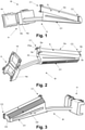
Figure 1 is a front perspective view of a lighting module of the lighting device proposed by the present invention, for a first example of embodiment. -
Figure 2 is another front perspective view of the lighting module offigure 1 , from a different viewpoint. -
Figure 3 is a rear perspective view of the lighting module offigure 1 . -
Figure 4 is another rear perspective view of the lighting module offigure 1 , taken from a different viewpoint than infigure 3 . -
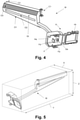
Figure 5 is another front perspective view of the lighting module offigure 1 , in which the lighting module is located on an imaginary prism used to indicate the dimensions of the lighting module. -
Figure 6 is another front elevation view of the lighting module offigure 1 , together with two enlarged details of its first and second type coupling configurations. -
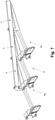
Figure 7 is a front perspective view of three lighting modules as those offigure 1 coupled together, for an implementation of the lighting device of the present invention. -
Figure 8 is a front perspective view of a lighting module of the lighting device proposed by the present invention, for a second example of embodiment. -
Figure 9 is another front perspective view of the lighting module offigure 8 , from a different viewpoint. -
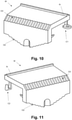
Figure 10 is a rear perspective view of the lighting module offigure 8 . -
Figure 11 is another rear perspective view of the lighting module offigure 8 , taken from a different viewpoint than infigure 10 . -
Figure 12 is another front perspective view of the lighting module offigure 8 , in which the lighting module is located on an imaginary prism used to indicate the dimensions of the lighting module. -
Figure 13 is another front elevation view of the lighting module offigure 8 , together with two enlarged details of its first and second type coupling configurations. -
Figure 14 is a front perspective view of three lighting modules as those offigure 8 coupled together, for an implementation of the lighting device of the present invention. -
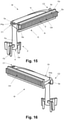
Figure 15 is a front perspective view of a lighting module of the lighting device proposed by the present invention, for a third example of embodiment. -
Figure 16 is another front perspective view of the lighting module offigure 15 , from a different viewpoint. -
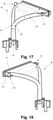
Figure 17 is a rear perspective view of the lighting module offigure 15 . -
Figure 18 is another rear perspective view of the lighting module offigure 15 , taken from a different viewpoint than infigure 17 . -
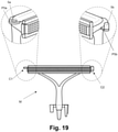
Figure 19 is another front elevation view of the lighting module offigure 15 , together with two enlarged details of its first and second type coupling configurations. -
Figure 20 is a front perspective view of three lighting modules as those offigure 15 coupled together, for an implementation of the lighting device of the present invention. -
Figure 21 is a front perspective view of a lighting module of the lighting device proposed by the present invention, for a fourth example of embodiment, similar to the third example of embodiment. -
Figure 22 is a rear perspective view of the lighting module of the lighting device offigure 21 . -
Figure 23 is a front perspective view of two lighting modules as that offigure 21 coupled together, with details of their first and second type coupling configurations. - Different examples of embodiments of the lighting device of the present invention are illustrated in the accompanying figures, all of which have in common that they include at least one lighting module comprising:
- a light guide G comprising a light entry zone Ge, an internal light transmission zone Gt and a light exit zone Gs, optically connected along an optical path; and
- a coupling configuration of a first type C1 and a coupling configuration of a second type C2, which is complementary to the coupling configuration of a first type C1, for coupling at least one adjacent lighting module Ma comprising at least one of said coupling configurations of a first type C1 or a second type C2, wherein the coupling configurations of a first type C1 and a second type C2 are arranged at locations of the lighting module M distant from the light entry zone Ge of the light guide G.
- In the second, third and fourth embodiments, i.e., those illustrated in
figures 8 to 23 , the coupling configurations of a first C1 and a second C2 type are arranged at locations of the lighting module M where they do not interfere with said optical path, and where they do not interfere with the light exit zone Gs of the light guide G. - Instead, for the first example of embodiment, i.e., that of
figures 1 to 8 , one of the coupling configurations, in particular that of a second typeC2 comprising projections 5b, is slightly interposed in the area of the section of the said optical path towards the light exit area Gs of the light guide G, in an area close to the same, as can be seen in detail inFigure 6 . In any event, in order to guarantee homogeneity and optimum light transmission inside the light guide G, theprojections 5b are also light transmitters, allowing light to pass towards the exit surface S, which will be described below. - A variant of said first example of embodiment for which there is no such interference is also covered by the present invention. This could be realised, for example, by only arranging the
projections 5b at the locations depicted infigure 6 , i.e., protruding above and below the elongate light exit surface S, but not including the cylindrical portion joining them which is now partially embedded in the light guide G. The body of the light guide G communicating saidprojections 5b is homogeneous with the areas of the adjacent light guides G, so that there are no internal reflections of light beams. - For all embodiments illustrated in the attached Figures, the locations of the lighting module M are coincident with and/or adjacent to the respective first and second regions of the outer contour of the light guide G, and the light exit zone Gs comprises an elongate light exit surface S extending in a longitudinal direction between the first Sa and second Sb opposite ends, which constitute said first and second regions of the outer contour of the light guide G.
- Also for all illustrated embodiments, the coupling configurations of a first C1 and a second C2 type comprise respectively at least one
opening 5a and at least oneprotrusion 5b configured to fit, respectively, into aprotrusion 5b and anopening 5a of respective adjacent lighting modules Ma, illustrated infigures 7 ,14 ,20 , and23 . - In particular, for the first example of embodiment, the coupling configurations of a first C1 and a second C2 type comprise respectively two
openings 5a and twoprotrusions 5b, whereas for the second, third and fourth examples of embodiment they only comprise oneopening 5a and oneprotrusion 5b. - Also for all illustrated embodiments, the
opening 5a is a throughhole 5a (although it could be a blind hole for non-illustrated variants) which is defined in a flange P5a extending from said first region of the outer contour of the light guide G or from the free end of an intermediate portion P5ai extending from said first region of the outer contour of the light guide G, and theprotrusion 5b extends along a longitudinal axis from the second region of the outer contour of the light guide G or from the free end of an intermediate portion P5b extending from the outer contour of the light guide G, wherein said longitudinal axis is parallel to the geometrical axis of saidopening 5a, which in turn is orthogonal to the longitudinal direction along which the elongate light exit surface S extends. - In particular, as regards the first example of embodiment, as seen in particular in the enlarged detail on the left in
figure 6 , each of the twoopenings 5a is an orifice defined in a respective flange P5a, both of which extend from locations adjacent to the first end Sa of the elongated light exit surface S; in this case, according to the position illustrated by the central view offigure 6 , both flanges P5a extend to the left from locations arranged adjacent to but slightly behind the elongate light exit surface S, and one of them slightly above and the other slightly below the elongate light exit surface S. - As regards the
protrusions 5b, for the first example of embodiment, as can be seen in particular in the enlarged detail on the right infigure 6 , each of the twoprotrusions 5b has a spherical cap shape extending, according to the position illustrated by the central view infigure 6 , one upwards and the other downwards from respective locations adjacent to the second end Sb of the elongate light exit surface S, which in this case are arranged slightly behind the elongate light exit surface S. - With regard to the second example of embodiment, as seen in particular in the enlarged detail on the left in
figure 13 , thesingle opening 5a is a hole which is defined in a respective flange P5a extending from a location adjacent to the first end Sa of the elongate light exit surface S; in this case, according to the position illustrated by the central view offigure 13 , the flange P5a extends to the left from the free end of an intermediate portion or arm P5ai which in turn extends downwards from a location adjacent to the first end Sa of the elongate light exit surface S, in this case, from an adjacent location arranged below and slightly behind the elongate light exit surface S. - Similarly, in the second example of embodiment, as regards the
single protrusion 5b, as can be seen in particular in the enlarged detail on the right infigure 13 , this has a conical shape and extends, according to the position illustrated by the central view offigure 13 , upwards from the free end of an L-shaped intermediate portion P5b extending downwards from a location adjacent to the second end Sb of the elongated light exit surface S, in this case, from an adjacent location disposed below and slightly behind the elongate light exit surface S. - For the third and fourth embodiments, as seen in particular in the enlarged details on the left of
figures 19 and23 , thesingle opening 5a is an orifice made in a respective flange P5a extending from a location adjacent to the first end Sa of the elongate light exit surface S; in this case, according to the position illustrated by the central view offigures 19 and23 , the tab P5a extends to the left from a location arranged adjacent to but behind the elongate light exit surface S. - With respect to the
single projection 5b, for the third and fourth embodiments, as can be seen in particular in the enlarged detail on the right infigures 19 and23 , this has a cylindrical or slightly conical shape and extends, according to the position illustrated by the central view offigures 19 and23 , upwards from the free end of an intermediate portion P5b extending to the right from a location adjacent to the second end Sb of the elongate light exit surface S, in this case, from an adjacent location arranged behind the elongate light exit surface S. - As can be seen in particular in
figures 13 ,19 and21 , according to the position of the lighting module M illustrated therein, the flanges P5a are located in a plane above the plane from which theprotrusions 5b extend upwards. - The same can be said with respect to the upper flange P5a and the
protrusion 5b of the first embodiment, for which the reverse situation occurs for the lower flange P5a and theprotrusion 5b, i.e., that lower flange P5a is in a plane below the plane from which thelower protrusion 5b extends upwards. - In all illustrated embodiments, the coupling configurations of a first type C1 and a second type C2 allow a freely rotatable coupling between the lighting module M and the adjacent lighting module Ma coupled thereto, to rotate relative to each other about a rotational axis along a given angular displacement. This aspect can be seen in
figures 7 ,14 ,20 and23 , where several modules M, Ma are coupled to each other slightly angularly displaced along said axis of rotation, to form a curve-shaped arrangement of lighting modules M, Ma, and in particular a total light output surface formed by the elongated light output surfaces S of the consecutively arranged modules M, Ma, or to achieve a good fit between the modules in order to compensate for manufacturing tolerances. -
Figure 23 illustrates by means of two vertical arrow lines pointing in opposite directions the relative movement that is carried out between the modules M, Ma to couple them together by inserting theprotrusion 5b in theorifice 5a, as well as, by means of a circular arrow line, the aforementioned rotation, in this case around the axis E illustrated therein, which can be carried out once said coupling has taken place. - In particular, said
figures 7 ,14 ,20 and23 show how the modules M, Ma illustrated therein are coupled together in such a way that their respective elongate light-emitting surfaces S form a continuous illuminated surface, by placing in contact the first end Sa of the elongate light surface of the module M with the second end Sb of the elongate light surface S of the adjacent lighting module Ma arranged to its right (according to the position illustrated infigures 7 ,14 ,20 and23 ), and, for the examples of embodiments offigures 7 ,14 and20 , by placing in contact the second end Sb of the elongate light surface of the module M with the first end Sa of the elongate light surface S of the adjacent light module Ma arranged to its left. - For the fourth example of embodiment, the continuity achieved in the continuous illuminated surface is even greater than for the other examples of embodiments since, as can be seen in
figures 21, 22 and23 : - the second end Sb of the elongate light exit surface S includes a protruding portion Ssb configured to engage with a recessed portion Rsa defined adjacent to a first end Sa of an elongate light exit surface S of an adjacent lighting module Ma, such that the protruding portion Ssb contacts the first end Sa of the elongate light exit surface S of the adjacent lighting module Ma for all possible positions along the aforementioned specified angular displacement; and
- the first end Sa of the elongate light exit surface S includes a recessed portion Rsa equal to the recessed portion Rsa of the adjacent lighting module Ma, to engage with a protruding portion Ssb, equal to said protruding portion Ssb, which is included in a second end Sb of an elongate light exit surface S of an adjacent lighting module Ma, such that the recessed portion Rsa contacts the second end Sb of the elongate light exit surface S of the adjacent lighting module Ma for all adoptable positions along said specified angular displacement.
- Obviously, in order for the continuity on the illuminated surface to benefit from such recessed portions Rsa and protrusions Sds, these and the light guide G as a whole must be designed and configured in such a way that the light reaches them.
- The configuration of the recessed portions Rsa and protrusions Ssb can also be incorporated in non-illustrated variants of the first, second and third examples of embodiments.
- As can be seen from
figures 7 ,14 ,20 and23 , an external observer would see an elongate illuminated surface, as if it were a light-emitting surface of a single body. The generation of this elongated light-emitting surface as a combination of several light-emitting surfaces Gs of a number of lighting modules M has the advantage of avoiding complex mathematical calculations in the dimensioning of the elongate light guides and their respective optics to achieve a high degree of homogeneity over the entire surface to be illuminated. - For the second third and fourth illustrated embodiments, each lighting module M, Ma, has one or two ribs N projecting from one or two respective locations on the contour of the light guide G slightly behind the elongate light exit surface S. The purpose of such ribs N is to place the light guide G inside a protective casing (not illustrated) of the lighting device.
- In all embodiments, the light passing through the respective light guides G is sufficiently scattered so as to be spread over all the elongated illuminating surfaces S by a number of internal reflecting and/or scattering and/or diffusing surfaces.
- For this purpose, in all illustrated embodiments, their respective light guide G comprises optical configurations arranged in one or more of the light input zones Ge, internal transmission zones Gt or output zones Gs and/or at another point of said optical path, for reflection and/or scattering and/or diffusion of the light beams introduced by the light source.
- In particular, with regard to the first example of embodiment, as shown in
figure 3 , where the direction of the light beams is indicated by dashed arrow lines, such optical configurations are as follows: - Reflecting
optics 01, allowing the beams to be distributed over the entire width of the elongate light exit surface S. - Opening O2 for diffusion and scattering of the light beams. Some of the light beams reflected internally in 01 pass through O2, while others bounce off the first side of the opening O2 back to 01. This results in an increased scattering of the light beams.
- Reflecting surface or optics O3 directing the light beams towards the elongate light exit surface S, which, although not the case illustrated, may also have optics or etchings to increase the homogeneity of the light.
- With regard to the second example of embodiment, as shown in
figure 9 (andfigure 10 ), where the direction of the light beams is indicated by dashed arrow lines, such optical configurations are as described below: - The light emitted by the light source enters the inner hexagonal channel defining the tubular element Fa, which has an
optics 01 at the entrance surface to scatter the light beams, and another optics (not shown) at the other end to direct the light beams towards the next inner reflection surface O2. - Optics or internal reflecting surface O2, which allows the beams to be distributed over the entire elongate light exit surface S.
- Optics or reflecting surface O3, which directs the light beams towards the elongate light exit surface S.
- Elongate light exit surface S, which in this case has etchings or optics O4 to increase the homogeneity of the light.
- As regards the third example of embodiment, as shown in
figure 17 (andfigure 16 ), in which the direction of the light beams is also indicated by dashed arrow lines, such optical configurations are as follows: - The light emitted by the light source enters the conduction channel defined by tubular element Fa, which has an internal optics (the location of which is indicated as 01) on the surface of the light entry zone Ga to scatter the light beams towards the zone. The channel has a bifurcation B at the other end which includes an internal optics (location shown as O2) to direct the light beams into the internal transmission zone Gt.
- Optics or reflecting surface O3, which directs the light beams towards the elongate light exit surface S.
- Elongate light exit surface S, which in this case has etchings or optics O4 to increase the homogeneity of the light.
- As regards the fourth example of embodiment, a variant of same includes identical or similar optical configurations as the third example of embodiment.
- In the illustrated embodiments, each of the lighting modules M and the adjacent lighting modules Ma includes or is at least configured to receive light from at least one light source (not illustrated) configured and arranged to introduce light beams into the light input zone Ge of said light guide G. Thus, the light from a lighting module M is not optically communicated with an adjacent lighting module Ma, but is optically transferred from the light input zone Ge to the light output zone Gs. It is noted that the light input zone Ge of a lighting module M is not connected to the light output zone Gs of an adjacent lighting module Ma.
- Also, in the illustrated embodiments, each of the lighting modules M and adjacent lighting modules Ma includes or is at least configured to carry a printed circuit board (not illustrated) with electrical/electronic circuitry, to which the at least one light source (such as an LED) is mechanically and electrically connected, and comprises elements F for positioning and fixing the printed circuit board and the light source so that the light source is arranged to introduce light beams into the light entry zone Ge of the light guide G.
- In the first example of embodiment, as shown in
figures 1 to 7 , each lighting module M and adjacent lighting module Ma comprises a casing H which includes a housing Ha for the printed circuit board and light source, and which includes a hinged cover Ht (for example by means of a film hinge Hb) for closing the housing Ha. As can be seen infigure 4 , from a back wall of the housing Ha, positioning and fixing elements F for both the printed circuit board and the light source of the light source extend from the protrusion Fd and from a small portion or tubular element Fa surrounding a hole in which to insert at least part of the light source, and which therefore constitutes the light entry zone Ge. - In the second example of embodiment, as shown in
figures 8 to 14 , the positioning and fixing elements F comprise a series of conical shaped arms Fb extending from a wall of the internal transmission zone Gt of the light guide G, the purpose of which is to be inserted into respective through holes of the printed circuit board (and optionally soldered to the same) in order to centre and fix the same. Such positioning and fixing elements F also comprise a tubular element Fa, at least partially hollow, which also extends from the same wall and whose purpose is to receive inside its end portion at least part of the light source, such end portion of the tubular element Fa constituting therefore the light entry zone Ge. - Similarly, in the third embodiment and as shown in
figures 15 to 20 , the positioning and fixing elements F also comprise a series of conical shaped arms Fb and a tubular element Fa, for the same purpose as those of the second embodiment, but with the difference that in this case the tubular element Fa extends from a converging portion of the inner transmission zone Gt of the light guide G, and the arms Fb extend parallel to the tubular element Fa from respective appendages A extending radially from the outer contour of the tubular element Fa. - For the fourth embodiment, the positioning and fixing elements F comprise a tubular element Fa similar to that of the third embodiment, lacking the arms Fb but having a pair of protrusions Fc extending radially from the outer contour of the tubular element Fa.
- In the illustrated embodiments, the light guide G and the coupling configurations of a first C1 and a second C2 type are part of the same one-piece body, of which the positioning and fixing elements F and, where applicable, the housing H are also part.
- Finally,
figures 5 and12 show dimensions of the lighting module of the present invention for the first and second embodiments of two corresponding prototypes manufactured by the present inventors. - In particular, with regard to the first embodiment, X = 39.5 mm, Y = 117 mm and Z = 37.5 mm, and with regard to the second embodiment, X = 26.5 mm, Y = 45 ÷ 70 mm and Z = 23 mm.
- Such dimensions are obviously to be taken in a non-limiting manner, and are provided herein only as examples of implementations which have been carried out in practice of such first and second examples of embodiments of the lighting device of the present invention.
-
- M:
- Lighting module
- Ma:
- Adjacent lighting module
- G:
- Light guide
- Ge:
- Light entry zone
- Gt:
- Internal light transmission zone
- Gs:
- Light exit zone
- C1:
- Coupling configuration of the first type
- 5a:
- Opening of C1
- P5a:
- Flange in which 5a is defined
- C2:
- Coupling configuration of a second type
- 5b:
- Protrusion of C2
- P5b:
- Intermediate portion from which 5b extends
- S:
- Elongate light exit surface
- Sa:
- First end of S
- Rsa:
- Recessed portion of Sa
- Sb:
- Second end of S
- Ssb:
- Protruding portion of Sb
- F:
- Positioning and fixing elements
- Fa:
- Tubular element
- Fb:
- Arms
- Fc:
- Protrusions
- Fd:
- Protrusion
- A:
- Appendages
- H:
- Casing
- Ha:
- Housing of H
- Ht:
- Cover of H
- Hb:
- Film hinge
- B:
- Bifurcation
- N:
- Ribs
- A person skilled in the art could make changes and modifications to the examples of embodiment described without going beyond the scope of the invention as defined in the attached claims.
Claims (19)
- Lighting device comprising at least one lighting module (M) which in turn comprises:- a light guide (G) comprising a light entry zone (Ge), an internal light transmission zone (Gt) and a light exit zone (Gs), optically communicating with each other along an optical path; and- a coupling configuration of a first type (C1) and a coupling configuration of a second type (C2), which is complementary to said coupling configuration of a first type (C1), for coupling at least one adjacent lighting module (Ma) comprising at least one of said coupling configurations of a first (C1) or a second (C2) type;the lighting device being characterised in that said coupling configurations of a first (C1) and a second (C2) type are arranged at locations of the lighting module (M) distant from said light entry zone (Ge) of the light guide (G).
- Lighting device according to claim 1, wherein the coupling configurations of a first (C1) and a second (C2) type are arranged at locations on the lighting module (M) where they do not interfere with said optical path.
- Lighting device according to claim 1 or 2, wherein the coupling configurations of a first (C1) and a second (C2) type are arranged at locations on the lighting module (M) where they do not interfere with the light exit area (Gs) of the light guide (G).
- Lighting device according to claim 1, 2 or 3, wherein said locations of the lighting module (M) are coincident with and/or adjacent to respective first and second regions of the outer contour of said light guide (G).
- Lighting device according to claim 1, 2, 3 or 4, wherein the coupling configurations of a fist type (C1) and a second type (C2) respectively comprise at least one opening (5a) and at least one protrusion (5b) configured to fit, respectively, in a protrusion (5b) and an opening (5a) of respective adjacent lighting modules (Ma).
- Lighting device according to claim 5, wherein at least one of said openings (5a) and said protrusions (5b) is a centring element configured to centre the same with respect to the protrusion (5b) or opening (5a) of the adjacent lighting module (Ma) to be coupled, during the coupling operation.
- Lighting device according to claim 5 or 6, when depending on claim 3, wherein said opening (5a) is an orifice (5a) made in a flange (P5a) extending from said first region of the outer contour of the light guide (G) or from the free end of an intermediate portion (P5ai) extending from said first region of the outer contour of the light guide (G).
- Lighting device according to claim 7, when depending on 5, wherein said protrusion (5b) extends along at least one longitudinal axis from said second region of the outer contour of the light guide (G) or from the free end of an intermediate portion (P5b) extending from said second region of the outer contour of the light guide (G), wherein said longitudinal axis is parallel to the geometrical axis of said orifice (5a).
- Lighting device according to claim 4 or any one of claims 5 to 8 when depending on claim 4, wherein said light exit zone (Gs) comprises an elongate light exit surface (S) extending in a longitudinal direction between said first (Sa) and second (Sb) opposite ends, which constitute said first and second regions of the outer contour of the light guide (G).
- Lighting device according to claim 9 when depending on claim 8, wherein said geometrical axis of the orifice (5a) is orthogonal to said longitudinal direction.
- Lighting device according to any one of the preceding claims, wherein the coupling configurations of a first (C1) and a second (C2) type allow a freely rotatable coupling between said lighting module (M) and said adjacent lighting module (Ma), to rotate relative to each other about a rotational axis along a specified angular displacement.
- Lighting device according to claim 11 when depending on claim 9 or 10, wherein:- said second end (Sb) of the elongate light exit surface (S) includes a protruding portion (Ssb) configured to engage a recessed portion (Rsa) defined adjacent to a first end (Sa) of an elongate light exit surface (S) of an adjacent lighting module (Ma), so that said protruding portion (Ssb) contacts the first end (Sa) of said elongate light exit surface (S) of the adjacent lighting module (Ma) for all possible positions along said specified angular displacement; and- said first end (Sa) of the elongate light exit surface (S) includes a recessed portion (Rsa) identical to said recessed portion (Rsa) of the adjacent lighting module (Ma), to engage a protruding portion (Ssb), identical to said protruding portion (Ssb), which is included in a second end (Sb) of an elongate light exit surface (S) of an adjacent lighting module (Ma), so that said recessed portion (Rsa) contacts the second end (Sb) of said elongate light exit surface (S) of said adjacent lighting module (Ma) for all possible positions along said specified angular displacement.
- Lighting device according to any one of the preceding claims, wherein said lighting module (M) further comprises:- at least one light source configured and arranged to introduce light beams into said light entry zone (Ge) of said light guide (G);- a printed circuit board with electrical/electronic circuitry, to which said at least one light source is mechanically and electrically connected;- elements (F) for positioning and fixing said printed circuit board and said at least one light source so that the at least one light source is arranged for said introduction of light beams into the light entry zone (Ge) of the light guide (G); and- a casing (H) for housing said printed circuit board.
- Device according to any one of the preceding claims, wherein at least said light guide (G) and said coupling configurations of a first type (C1) and of a second type (C2) form part of the same one-piece body.
- Device according to claim 14 when depending on claim 13, wherein said positioning and fixing elements (F) and/or said casing (H) form part of said one-piece body.
- Lighting device according to any one of the preceding claims, further comprising said adjacent lighting module (Ma), which is defined according to said lighting module (M) and is coupled thereto by its coupling configuration of a first type (C1) or a second type (C2).
- Lighting device according to claim 16 when depending on 9, 10 or 12, wherein the lighting module (M) and the adjacent lighting module (Ma) are coupled to each other so that their respective elongate light output surfaces (S) form a continuous illuminated surface.
- Lighting device according to claim 17, wherein said continuous illuminated surface is formed by contacting the first end (Sa) of the elongate light surface of the lighting module (M) with the second end (Sb) of the elongate light surface of the adjacent lighting module (Ma), or vice versa.
- Lighting device according to any one of claims 16 to 18 , wherein said adjacent lighting module (Ma) is a first adjacent lighting module (Ma), where the lighting device further comprises a second adjacent lighting module (Ma), which is defined according to said lighting module (M) and is coupled thereto by the coupling configuration of a second type (C2) or a first type (C1) type in which the first adjacent lighting module (Ma) is not coupled.
Applications Claiming Priority (1)
| Application Number | Priority Date | Filing Date | Title |
|---|---|---|---|
| ES202030826A ES2893999B2 (en) | 2020-08-03 | 2020-08-03 | LIGHTING DEVICE |
Publications (2)
| Publication Number | Publication Date |
|---|---|
| EP3951257A1 true EP3951257A1 (en) | 2022-02-09 |
| EP3951257B1 EP3951257B1 (en) | 2023-02-01 |
Family
ID=77249682
Family Applications (1)
| Application Number | Title | Priority Date | Filing Date |
|---|---|---|---|
| EP21189364.9A Active EP3951257B1 (en) | 2020-08-03 | 2021-08-03 | Lighting device |
Country Status (2)
| Country | Link |
|---|---|
| EP (1) | EP3951257B1 (en) |
| ES (2) | ES2893999B2 (en) |
Citations (5)
| Publication number | Priority date | Publication date | Assignee | Title |
|---|---|---|---|---|
| DE19904644A1 (en) * | 1999-02-05 | 2000-08-10 | Hella Kg Hueck & Co | Lamp for vehicles, especially for cars, has light-conducting element with light propagation direction vertical to light exit face, and arranged to be inclined relative to optical axis |
| US20040208016A1 (en) | 2003-03-11 | 2004-10-21 | Koito Manufacturing Co., Ltd. | Vehicular lamp |
| US20110038178A1 (en) * | 2009-08-11 | 2011-02-17 | Sony Corporation | Planar illumination device |
| US20150078025A1 (en) * | 2013-09-18 | 2015-03-19 | Automotive Lighting Reutlingen Gmbh | Lighting device in a motor vehicle |
| US20160245986A1 (en) * | 2015-02-25 | 2016-08-25 | Rambus Delaware Llc | Light guide assembly, housing assembly, and lighting assembly including same |
Family Cites Families (3)
| Publication number | Priority date | Publication date | Assignee | Title |
|---|---|---|---|---|
| GB1411877A (en) * | 1973-02-27 | 1975-10-29 | Cavis Cavetti Isolati Spa | Fastener for light-guide cables |
| DE202006003392U1 (en) * | 2006-03-03 | 2006-05-04 | Fer Fahrzeugelektrik Gmbh | Motor vehicle headlamp e.g. side flash light, has optical fiber arrangement with fasteners that connects arrangement directly with housing, such that arrangement extends between fasteners in self supporting manner |
| FR3002794B1 (en) * | 2013-03-04 | 2015-03-20 | Valeo Vision Belgique | LIGHTING AND / OR SIGNALING DEVICE FOR A MOTOR VEHICLE HAVING A LIGHT GUIDE |
-
2020
- 2020-08-03 ES ES202030826A patent/ES2893999B2/en not_active Expired - Fee Related
-
2021
- 2021-08-03 ES ES21189364T patent/ES2939314T3/en active Active
- 2021-08-03 EP EP21189364.9A patent/EP3951257B1/en active Active
Patent Citations (5)
| Publication number | Priority date | Publication date | Assignee | Title |
|---|---|---|---|---|
| DE19904644A1 (en) * | 1999-02-05 | 2000-08-10 | Hella Kg Hueck & Co | Lamp for vehicles, especially for cars, has light-conducting element with light propagation direction vertical to light exit face, and arranged to be inclined relative to optical axis |
| US20040208016A1 (en) | 2003-03-11 | 2004-10-21 | Koito Manufacturing Co., Ltd. | Vehicular lamp |
| US20110038178A1 (en) * | 2009-08-11 | 2011-02-17 | Sony Corporation | Planar illumination device |
| US20150078025A1 (en) * | 2013-09-18 | 2015-03-19 | Automotive Lighting Reutlingen Gmbh | Lighting device in a motor vehicle |
| US20160245986A1 (en) * | 2015-02-25 | 2016-08-25 | Rambus Delaware Llc | Light guide assembly, housing assembly, and lighting assembly including same |
Also Published As
| Publication number | Publication date |
|---|---|
| ES2893999B2 (en) | 2022-10-28 |
| ES2893999A1 (en) | 2022-02-10 |
| EP3951257B1 (en) | 2023-02-01 |
| ES2939314T3 (en) | 2023-04-20 |
Similar Documents
| Publication | Publication Date | Title |
|---|---|---|
| JP5263193B2 (en) | Proximity sensor | |
| US7033052B2 (en) | Vehicular lamp | |
| CN106838759B (en) | Lighting device for vehicle | |
| EP3599418B1 (en) | Vehicular lamp comprising a light guide | |
| CN114787555A (en) | Lamp for a motor vehicle comprising a light guide | |
| EP3096078A1 (en) | Illuminating device | |
| CN107110458B (en) | Lighting device | |
| US7341366B2 (en) | Projector type vehicle headlamp unit | |
| EP3228924A1 (en) | Vehicle lamp | |
| JPH11273795A (en) | Modular jack with indicator | |
| EP4063720A1 (en) | Light guide assembly, vehicle light and vehicle | |
| EP3951257B1 (en) | Lighting device | |
| WO2018094242A1 (en) | Illumination assembly for a vehicle | |
| CN110274210B (en) | Vehicle headlamp | |
| EP1954978B1 (en) | Lighting device and method for directing light | |
| JP7407668B2 (en) | lighting unit | |
| KR100997222B1 (en) | Modules having a plurality of circuit boards stacked apart by a predetermined distance and the optical connector for the module | |
| JP6901315B2 (en) | Lamp unit and vehicle lamp | |
| CN110274209B (en) | Vehicle headlamp | |
| CN110071766B (en) | modules and electronics | |
| CN223609965U (en) | Multi-light source lighting device | |
| CN209801360U (en) | Vehicle dipped beam light distribution structure | |
| KR102633282B1 (en) | Two-line linear lamp with LED light source efficiency increase structure | |
| CN220749902U (en) | Optical structure combining light guide and thick wall and car lamp and car comprising optical structure | |
| CN224135719U (en) | Signal light module and vehicle lights |
Legal Events
| Date | Code | Title | Description |
|---|---|---|---|
| PUAI | Public reference made under article 153(3) epc to a published international application that has entered the european phase |
Free format text: ORIGINAL CODE: 0009012 |
|
| STAA | Information on the status of an ep patent application or granted ep patent |
Free format text: STATUS: THE APPLICATION HAS BEEN PUBLISHED |
|
| AK | Designated contracting states |
Kind code of ref document: A1 Designated state(s): AL AT BE BG CH CY CZ DE DK EE ES FI FR GB GR HR HU IE IS IT LI LT LU LV MC MK MT NL NO PL PT RO RS SE SI SK SM TR |
|
| STAA | Information on the status of an ep patent application or granted ep patent |
Free format text: STATUS: REQUEST FOR EXAMINATION WAS MADE |
|
| 17P | Request for examination filed |
Effective date: 20220728 |
|
| GRAP | Despatch of communication of intention to grant a patent |
Free format text: ORIGINAL CODE: EPIDOSNIGR1 |
|
| RBV | Designated contracting states (corrected) |
Designated state(s): AL AT BE BG CH CY CZ DE DK EE ES FI FR GB GR HR HU IE IS IT LI LT LU LV MC MK MT NL NO PL PT RO RS SE SI SK SM TR |
|
| STAA | Information on the status of an ep patent application or granted ep patent |
Free format text: STATUS: GRANT OF PATENT IS INTENDED |
|
| INTG | Intention to grant announced |
Effective date: 20220908 |
|
| GRAS | Grant fee paid |
Free format text: ORIGINAL CODE: EPIDOSNIGR3 |
|
| GRAA | (expected) grant |
Free format text: ORIGINAL CODE: 0009210 |
|
| STAA | Information on the status of an ep patent application or granted ep patent |
Free format text: STATUS: THE PATENT HAS BEEN GRANTED |
|
| AK | Designated contracting states |
Kind code of ref document: B1 Designated state(s): AL AT BE BG CH CY CZ DE DK EE ES FI FR GB GR HR HU IE IS IT LI LT LU LV MC MK MT NL NO PL PT RO RS SE SI SK SM TR |
|
| REG | Reference to a national code |
Ref country code: GB Ref legal event code: FG4D |
|
| REG | Reference to a national code |
Ref country code: CH Ref legal event code: EP Ref country code: AT Ref legal event code: REF Ref document number: 1547026 Country of ref document: AT Kind code of ref document: T Effective date: 20230215 |
|
| REG | Reference to a national code |
Ref country code: DE Ref legal event code: R096 Ref document number: 602021001345 Country of ref document: DE |
|
| REG | Reference to a national code |
Ref country code: IE Ref legal event code: FG4D |
|
| REG | Reference to a national code |
Ref country code: ES Ref legal event code: FG2A Ref document number: 2939314 Country of ref document: ES Kind code of ref document: T3 Effective date: 20230420 |
|
| REG | Reference to a national code |
Ref country code: LT Ref legal event code: MG9D |
|
| REG | Reference to a national code |
Ref country code: NL Ref legal event code: MP Effective date: 20230201 |
|
| P01 | Opt-out of the competence of the unified patent court (upc) registered |
Effective date: 20230526 |
|
| REG | Reference to a national code |
Ref country code: AT Ref legal event code: MK05 Ref document number: 1547026 Country of ref document: AT Kind code of ref document: T Effective date: 20230201 |
|
| PG25 | Lapsed in a contracting state [announced via postgrant information from national office to epo] |
Ref country code: RS Free format text: LAPSE BECAUSE OF FAILURE TO SUBMIT A TRANSLATION OF THE DESCRIPTION OR TO PAY THE FEE WITHIN THE PRESCRIBED TIME-LIMIT Effective date: 20230201 Ref country code: PT Free format text: LAPSE BECAUSE OF FAILURE TO SUBMIT A TRANSLATION OF THE DESCRIPTION OR TO PAY THE FEE WITHIN THE PRESCRIBED TIME-LIMIT Effective date: 20230601 Ref country code: NO Free format text: LAPSE BECAUSE OF FAILURE TO SUBMIT A TRANSLATION OF THE DESCRIPTION OR TO PAY THE FEE WITHIN THE PRESCRIBED TIME-LIMIT Effective date: 20230501 Ref country code: NL Free format text: LAPSE BECAUSE OF FAILURE TO SUBMIT A TRANSLATION OF THE DESCRIPTION OR TO PAY THE FEE WITHIN THE PRESCRIBED TIME-LIMIT Effective date: 20230201 Ref country code: LV Free format text: LAPSE BECAUSE OF FAILURE TO SUBMIT A TRANSLATION OF THE DESCRIPTION OR TO PAY THE FEE WITHIN THE PRESCRIBED TIME-LIMIT Effective date: 20230201 Ref country code: LT Free format text: LAPSE BECAUSE OF FAILURE TO SUBMIT A TRANSLATION OF THE DESCRIPTION OR TO PAY THE FEE WITHIN THE PRESCRIBED TIME-LIMIT Effective date: 20230201 Ref country code: HR Free format text: LAPSE BECAUSE OF FAILURE TO SUBMIT A TRANSLATION OF THE DESCRIPTION OR TO PAY THE FEE WITHIN THE PRESCRIBED TIME-LIMIT Effective date: 20230201 Ref country code: AT Free format text: LAPSE BECAUSE OF FAILURE TO SUBMIT A TRANSLATION OF THE DESCRIPTION OR TO PAY THE FEE WITHIN THE PRESCRIBED TIME-LIMIT Effective date: 20230201 |
|
| PG25 | Lapsed in a contracting state [announced via postgrant information from national office to epo] |
Ref country code: SE Free format text: LAPSE BECAUSE OF FAILURE TO SUBMIT A TRANSLATION OF THE DESCRIPTION OR TO PAY THE FEE WITHIN THE PRESCRIBED TIME-LIMIT Effective date: 20230201 Ref country code: PL Free format text: LAPSE BECAUSE OF FAILURE TO SUBMIT A TRANSLATION OF THE DESCRIPTION OR TO PAY THE FEE WITHIN THE PRESCRIBED TIME-LIMIT Effective date: 20230201 Ref country code: IS Free format text: LAPSE BECAUSE OF FAILURE TO SUBMIT A TRANSLATION OF THE DESCRIPTION OR TO PAY THE FEE WITHIN THE PRESCRIBED TIME-LIMIT Effective date: 20230601 Ref country code: GR Free format text: LAPSE BECAUSE OF FAILURE TO SUBMIT A TRANSLATION OF THE DESCRIPTION OR TO PAY THE FEE WITHIN THE PRESCRIBED TIME-LIMIT Effective date: 20230502 Ref country code: FI Free format text: LAPSE BECAUSE OF FAILURE TO SUBMIT A TRANSLATION OF THE DESCRIPTION OR TO PAY THE FEE WITHIN THE PRESCRIBED TIME-LIMIT Effective date: 20230201 |
|
| PG25 | Lapsed in a contracting state [announced via postgrant information from national office to epo] |
Ref country code: SM Free format text: LAPSE BECAUSE OF FAILURE TO SUBMIT A TRANSLATION OF THE DESCRIPTION OR TO PAY THE FEE WITHIN THE PRESCRIBED TIME-LIMIT Effective date: 20230201 Ref country code: RO Free format text: LAPSE BECAUSE OF FAILURE TO SUBMIT A TRANSLATION OF THE DESCRIPTION OR TO PAY THE FEE WITHIN THE PRESCRIBED TIME-LIMIT Effective date: 20230201 Ref country code: EE Free format text: LAPSE BECAUSE OF FAILURE TO SUBMIT A TRANSLATION OF THE DESCRIPTION OR TO PAY THE FEE WITHIN THE PRESCRIBED TIME-LIMIT Effective date: 20230201 Ref country code: DK Free format text: LAPSE BECAUSE OF FAILURE TO SUBMIT A TRANSLATION OF THE DESCRIPTION OR TO PAY THE FEE WITHIN THE PRESCRIBED TIME-LIMIT Effective date: 20230201 Ref country code: CZ Free format text: LAPSE BECAUSE OF FAILURE TO SUBMIT A TRANSLATION OF THE DESCRIPTION OR TO PAY THE FEE WITHIN THE PRESCRIBED TIME-LIMIT Effective date: 20230201 |
|
| REG | Reference to a national code |
Ref country code: DE Ref legal event code: R097 Ref document number: 602021001345 Country of ref document: DE |
|
| PG25 | Lapsed in a contracting state [announced via postgrant information from national office to epo] |
Ref country code: SK Free format text: LAPSE BECAUSE OF FAILURE TO SUBMIT A TRANSLATION OF THE DESCRIPTION OR TO PAY THE FEE WITHIN THE PRESCRIBED TIME-LIMIT Effective date: 20230201 |
|
| PLBE | No opposition filed within time limit |
Free format text: ORIGINAL CODE: 0009261 |
|
| STAA | Information on the status of an ep patent application or granted ep patent |
Free format text: STATUS: NO OPPOSITION FILED WITHIN TIME LIMIT |
|
| 26N | No opposition filed |
Effective date: 20231103 |
|
| PG25 | Lapsed in a contracting state [announced via postgrant information from national office to epo] |
Ref country code: SI Free format text: LAPSE BECAUSE OF FAILURE TO SUBMIT A TRANSLATION OF THE DESCRIPTION OR TO PAY THE FEE WITHIN THE PRESCRIBED TIME-LIMIT Effective date: 20230201 |
|
| PG25 | Lapsed in a contracting state [announced via postgrant information from national office to epo] |
Ref country code: MC Free format text: LAPSE BECAUSE OF FAILURE TO SUBMIT A TRANSLATION OF THE DESCRIPTION OR TO PAY THE FEE WITHIN THE PRESCRIBED TIME-LIMIT Effective date: 20230201 |
|
| PG25 | Lapsed in a contracting state [announced via postgrant information from national office to epo] |
Ref country code: MC Free format text: LAPSE BECAUSE OF FAILURE TO SUBMIT A TRANSLATION OF THE DESCRIPTION OR TO PAY THE FEE WITHIN THE PRESCRIBED TIME-LIMIT Effective date: 20230201 |
|
| PG25 | Lapsed in a contracting state [announced via postgrant information from national office to epo] |
Ref country code: LU Free format text: LAPSE BECAUSE OF NON-PAYMENT OF DUE FEES Effective date: 20230803 |
|
| PG25 | Lapsed in a contracting state [announced via postgrant information from national office to epo] |
Ref country code: LU Free format text: LAPSE BECAUSE OF NON-PAYMENT OF DUE FEES Effective date: 20230803 |
|
| REG | Reference to a national code |
Ref country code: BE Ref legal event code: MM Effective date: 20230831 |
|
| REG | Reference to a national code |
Ref country code: IE Ref legal event code: MM4A |
|
| PG25 | Lapsed in a contracting state [announced via postgrant information from national office to epo] |
Ref country code: IT Free format text: LAPSE BECAUSE OF FAILURE TO SUBMIT A TRANSLATION OF THE DESCRIPTION OR TO PAY THE FEE WITHIN THE PRESCRIBED TIME-LIMIT Effective date: 20230201 |
|
| PG25 | Lapsed in a contracting state [announced via postgrant information from national office to epo] |
Ref country code: IE Free format text: LAPSE BECAUSE OF NON-PAYMENT OF DUE FEES Effective date: 20230803 |
|
| PG25 | Lapsed in a contracting state [announced via postgrant information from national office to epo] |
Ref country code: IE Free format text: LAPSE BECAUSE OF NON-PAYMENT OF DUE FEES Effective date: 20230803 |
|
| PG25 | Lapsed in a contracting state [announced via postgrant information from national office to epo] |
Ref country code: BE Free format text: LAPSE BECAUSE OF NON-PAYMENT OF DUE FEES Effective date: 20230831 |
|
| PG25 | Lapsed in a contracting state [announced via postgrant information from national office to epo] |
Ref country code: BG Free format text: LAPSE BECAUSE OF FAILURE TO SUBMIT A TRANSLATION OF THE DESCRIPTION OR TO PAY THE FEE WITHIN THE PRESCRIBED TIME-LIMIT Effective date: 20230201 |
|
| PG25 | Lapsed in a contracting state [announced via postgrant information from national office to epo] |
Ref country code: BG Free format text: LAPSE BECAUSE OF FAILURE TO SUBMIT A TRANSLATION OF THE DESCRIPTION OR TO PAY THE FEE WITHIN THE PRESCRIBED TIME-LIMIT Effective date: 20230201 |
|
| REG | Reference to a national code |
Ref country code: CH Ref legal event code: PL |
|
| PG25 | Lapsed in a contracting state [announced via postgrant information from national office to epo] |
Ref country code: CH Free format text: LAPSE BECAUSE OF NON-PAYMENT OF DUE FEES Effective date: 20240831 |
|
| PG25 | Lapsed in a contracting state [announced via postgrant information from national office to epo] |
Ref country code: CY Free format text: LAPSE BECAUSE OF FAILURE TO SUBMIT A TRANSLATION OF THE DESCRIPTION OR TO PAY THE FEE WITHIN THE PRESCRIBED TIME-LIMIT; INVALID AB INITIO Effective date: 20210803 |
|
| PGFP | Annual fee paid to national office [announced via postgrant information from national office to epo] |
Ref country code: ES Payment date: 20250916 Year of fee payment: 5 |
|
| PGFP | Annual fee paid to national office [announced via postgrant information from national office to epo] |
Ref country code: DE Payment date: 20250827 Year of fee payment: 5 |
|
| PGFP | Annual fee paid to national office [announced via postgrant information from national office to epo] |
Ref country code: GB Payment date: 20250826 Year of fee payment: 5 |
|
| PGFP | Annual fee paid to national office [announced via postgrant information from national office to epo] |
Ref country code: FR Payment date: 20250825 Year of fee payment: 5 |
|
| PG25 | Lapsed in a contracting state [announced via postgrant information from national office to epo] |
Ref country code: TR Free format text: LAPSE BECAUSE OF FAILURE TO SUBMIT A TRANSLATION OF THE DESCRIPTION OR TO PAY THE FEE WITHIN THE PRESCRIBED TIME-LIMIT Effective date: 20230201 |
|
| PG25 | Lapsed in a contracting state [announced via postgrant information from national office to epo] |
Ref country code: HU Free format text: LAPSE BECAUSE OF FAILURE TO SUBMIT A TRANSLATION OF THE DESCRIPTION OR TO PAY THE FEE WITHIN THE PRESCRIBED TIME-LIMIT; INVALID AB INITIO Effective date: 20210803 |