EP3951178B1 - Reciprocating compressor - Google Patents
Reciprocating compressor Download PDFInfo
- Publication number
- EP3951178B1 EP3951178B1 EP20788582.3A EP20788582A EP3951178B1 EP 3951178 B1 EP3951178 B1 EP 3951178B1 EP 20788582 A EP20788582 A EP 20788582A EP 3951178 B1 EP3951178 B1 EP 3951178B1
- Authority
- EP
- European Patent Office
- Prior art keywords
- cylinder
- housing
- intermediate chamber
- gas
- piston
- Prior art date
- Legal status (The legal status is an assumption and is not a legal conclusion. Google has not performed a legal analysis and makes no representation as to the accuracy of the status listed.)
- Active
Links
Images



Classifications
-
- F—MECHANICAL ENGINEERING; LIGHTING; HEATING; WEAPONS; BLASTING
- F04—POSITIVE - DISPLACEMENT MACHINES FOR LIQUIDS; PUMPS FOR LIQUIDS OR ELASTIC FLUIDS
- F04B—POSITIVE-DISPLACEMENT MACHINES FOR LIQUIDS; PUMPS
- F04B15/00—Pumps adapted to handle specific fluids, e.g. by selection of specific materials for pumps or pump parts
- F04B15/06—Pumps adapted to handle specific fluids, e.g. by selection of specific materials for pumps or pump parts for liquids near their boiling point, e.g. under subnormal pressure
- F04B15/08—Pumps adapted to handle specific fluids, e.g. by selection of specific materials for pumps or pump parts for liquids near their boiling point, e.g. under subnormal pressure the liquids having low boiling points
-
- F—MECHANICAL ENGINEERING; LIGHTING; HEATING; WEAPONS; BLASTING
- F04—POSITIVE - DISPLACEMENT MACHINES FOR LIQUIDS; PUMPS FOR LIQUIDS OR ELASTIC FLUIDS
- F04B—POSITIVE-DISPLACEMENT MACHINES FOR LIQUIDS; PUMPS
- F04B27/00—Multi-cylinder pumps specially adapted for elastic fluids and characterised by number or arrangement of cylinders
- F04B27/02—Multi-cylinder pumps specially adapted for elastic fluids and characterised by number or arrangement of cylinders having cylinders arranged oppositely relative to main shaft
-
- F—MECHANICAL ENGINEERING; LIGHTING; HEATING; WEAPONS; BLASTING
- F04—POSITIVE - DISPLACEMENT MACHINES FOR LIQUIDS; PUMPS FOR LIQUIDS OR ELASTIC FLUIDS
- F04B—POSITIVE-DISPLACEMENT MACHINES FOR LIQUIDS; PUMPS
- F04B27/00—Multi-cylinder pumps specially adapted for elastic fluids and characterised by number or arrangement of cylinders
- F04B27/04—Multi-cylinder pumps specially adapted for elastic fluids and characterised by number or arrangement of cylinders having cylinders in star- or fan-arrangement
- F04B27/0404—Details, component parts specially adapted for such pumps
- F04B27/0442—Supporting and guiding means for the pistons
-
- F—MECHANICAL ENGINEERING; LIGHTING; HEATING; WEAPONS; BLASTING
- F04—POSITIVE - DISPLACEMENT MACHINES FOR LIQUIDS; PUMPS FOR LIQUIDS OR ELASTIC FLUIDS
- F04B—POSITIVE-DISPLACEMENT MACHINES FOR LIQUIDS; PUMPS
- F04B39/00—Component parts, details, or accessories, of pumps or pumping systems specially adapted for elastic fluids, not otherwise provided for in, or of interest apart from, groups F04B25/00 - F04B37/00
- F04B39/0005—Component parts, details, or accessories, of pumps or pumping systems specially adapted for elastic fluids, not otherwise provided for in, or of interest apart from, groups F04B25/00 - F04B37/00 adaptations of pistons
-
- F—MECHANICAL ENGINEERING; LIGHTING; HEATING; WEAPONS; BLASTING
- F04—POSITIVE - DISPLACEMENT MACHINES FOR LIQUIDS; PUMPS FOR LIQUIDS OR ELASTIC FLUIDS
- F04B—POSITIVE-DISPLACEMENT MACHINES FOR LIQUIDS; PUMPS
- F04B39/00—Component parts, details, or accessories, of pumps or pumping systems specially adapted for elastic fluids, not otherwise provided for in, or of interest apart from, groups F04B25/00 - F04B37/00
- F04B39/04—Measures to avoid lubricant contaminating the pumped fluid
- F04B39/041—Measures to avoid lubricant contaminating the pumped fluid sealing for a reciprocating rod
-
- F—MECHANICAL ENGINEERING; LIGHTING; HEATING; WEAPONS; BLASTING
- F04—POSITIVE - DISPLACEMENT MACHINES FOR LIQUIDS; PUMPS FOR LIQUIDS OR ELASTIC FLUIDS
- F04B—POSITIVE-DISPLACEMENT MACHINES FOR LIQUIDS; PUMPS
- F04B39/00—Component parts, details, or accessories, of pumps or pumping systems specially adapted for elastic fluids, not otherwise provided for in, or of interest apart from, groups F04B25/00 - F04B37/00
- F04B39/06—Cooling; Heating; Prevention of freezing
-
- F—MECHANICAL ENGINEERING; LIGHTING; HEATING; WEAPONS; BLASTING
- F04—POSITIVE - DISPLACEMENT MACHINES FOR LIQUIDS; PUMPS FOR LIQUIDS OR ELASTIC FLUIDS
- F04B—POSITIVE-DISPLACEMENT MACHINES FOR LIQUIDS; PUMPS
- F04B39/00—Component parts, details, or accessories, of pumps or pumping systems specially adapted for elastic fluids, not otherwise provided for in, or of interest apart from, groups F04B25/00 - F04B37/00
- F04B39/06—Cooling; Heating; Prevention of freezing
- F04B39/064—Cooling by a cooling jacket in the pump casing
-
- F—MECHANICAL ENGINEERING; LIGHTING; HEATING; WEAPONS; BLASTING
- F04—POSITIVE - DISPLACEMENT MACHINES FOR LIQUIDS; PUMPS FOR LIQUIDS OR ELASTIC FLUIDS
- F04B—POSITIVE-DISPLACEMENT MACHINES FOR LIQUIDS; PUMPS
- F04B39/00—Component parts, details, or accessories, of pumps or pumping systems specially adapted for elastic fluids, not otherwise provided for in, or of interest apart from, groups F04B25/00 - F04B37/00
- F04B39/10—Adaptations or arrangements of distribution members
-
- F—MECHANICAL ENGINEERING; LIGHTING; HEATING; WEAPONS; BLASTING
- F04—POSITIVE - DISPLACEMENT MACHINES FOR LIQUIDS; PUMPS FOR LIQUIDS OR ELASTIC FLUIDS
- F04B—POSITIVE-DISPLACEMENT MACHINES FOR LIQUIDS; PUMPS
- F04B39/00—Component parts, details, or accessories, of pumps or pumping systems specially adapted for elastic fluids, not otherwise provided for in, or of interest apart from, groups F04B25/00 - F04B37/00
- F04B39/12—Casings; Cylinders; Cylinder heads; Fluid connections
-
- F—MECHANICAL ENGINEERING; LIGHTING; HEATING; WEAPONS; BLASTING
- F04—POSITIVE - DISPLACEMENT MACHINES FOR LIQUIDS; PUMPS FOR LIQUIDS OR ELASTIC FLUIDS
- F04B—POSITIVE-DISPLACEMENT MACHINES FOR LIQUIDS; PUMPS
- F04B39/00—Component parts, details, or accessories, of pumps or pumping systems specially adapted for elastic fluids, not otherwise provided for in, or of interest apart from, groups F04B25/00 - F04B37/00
- F04B39/12—Casings; Cylinders; Cylinder heads; Fluid connections
- F04B39/121—Casings
-
- F—MECHANICAL ENGINEERING; LIGHTING; HEATING; WEAPONS; BLASTING
- F04—POSITIVE - DISPLACEMENT MACHINES FOR LIQUIDS; PUMPS FOR LIQUIDS OR ELASTIC FLUIDS
- F04B—POSITIVE-DISPLACEMENT MACHINES FOR LIQUIDS; PUMPS
- F04B5/00—Machines or pumps with differential-surface pistons
- F04B5/02—Machines or pumps with differential-surface pistons with double-acting pistons
-
- F—MECHANICAL ENGINEERING; LIGHTING; HEATING; WEAPONS; BLASTING
- F04—POSITIVE - DISPLACEMENT MACHINES FOR LIQUIDS; PUMPS FOR LIQUIDS OR ELASTIC FLUIDS
- F04B—POSITIVE-DISPLACEMENT MACHINES FOR LIQUIDS; PUMPS
- F04B53/00—Component parts, details or accessories not provided for in, or of interest apart from, groups F04B1/00 - F04B23/00 or F04B39/00 - F04B47/00
- F04B53/02—Packing the free space between cylinders and pistons
-
- F—MECHANICAL ENGINEERING; LIGHTING; HEATING; WEAPONS; BLASTING
- F04—POSITIVE - DISPLACEMENT MACHINES FOR LIQUIDS; PUMPS FOR LIQUIDS OR ELASTIC FLUIDS
- F04B—POSITIVE-DISPLACEMENT MACHINES FOR LIQUIDS; PUMPS
- F04B53/00—Component parts, details or accessories not provided for in, or of interest apart from, groups F04B1/00 - F04B23/00 or F04B39/00 - F04B47/00
- F04B53/08—Cooling; Heating; Preventing freezing
-
- F—MECHANICAL ENGINEERING; LIGHTING; HEATING; WEAPONS; BLASTING
- F04—POSITIVE - DISPLACEMENT MACHINES FOR LIQUIDS; PUMPS FOR LIQUIDS OR ELASTIC FLUIDS
- F04B—POSITIVE-DISPLACEMENT MACHINES FOR LIQUIDS; PUMPS
- F04B53/00—Component parts, details or accessories not provided for in, or of interest apart from, groups F04B1/00 - F04B23/00 or F04B39/00 - F04B47/00
- F04B53/14—Pistons, piston-rods or piston-rod connections
- F04B53/144—Adaptation of piston-rods
- F04B53/146—Piston-rod guiding arrangements
-
- F—MECHANICAL ENGINEERING; LIGHTING; HEATING; WEAPONS; BLASTING
- F04—POSITIVE - DISPLACEMENT MACHINES FOR LIQUIDS; PUMPS FOR LIQUIDS OR ELASTIC FLUIDS
- F04B—POSITIVE-DISPLACEMENT MACHINES FOR LIQUIDS; PUMPS
- F04B53/00—Component parts, details or accessories not provided for in, or of interest apart from, groups F04B1/00 - F04B23/00 or F04B39/00 - F04B47/00
- F04B53/16—Casings; Cylinders; Cylinder liners or heads; Fluid connections
-
- F—MECHANICAL ENGINEERING; LIGHTING; HEATING; WEAPONS; BLASTING
- F04—POSITIVE - DISPLACEMENT MACHINES FOR LIQUIDS; PUMPS FOR LIQUIDS OR ELASTIC FLUIDS
- F04B—POSITIVE-DISPLACEMENT MACHINES FOR LIQUIDS; PUMPS
- F04B15/00—Pumps adapted to handle specific fluids, e.g. by selection of specific materials for pumps or pump parts
- F04B15/06—Pumps adapted to handle specific fluids, e.g. by selection of specific materials for pumps or pump parts for liquids near their boiling point, e.g. under subnormal pressure
- F04B15/08—Pumps adapted to handle specific fluids, e.g. by selection of specific materials for pumps or pump parts for liquids near their boiling point, e.g. under subnormal pressure the liquids having low boiling points
- F04B2015/081—Liquefied gases
-
- F—MECHANICAL ENGINEERING; LIGHTING; HEATING; WEAPONS; BLASTING
- F04—POSITIVE - DISPLACEMENT MACHINES FOR LIQUIDS; PUMPS FOR LIQUIDS OR ELASTIC FLUIDS
- F04B—POSITIVE-DISPLACEMENT MACHINES FOR LIQUIDS; PUMPS
- F04B15/00—Pumps adapted to handle specific fluids, e.g. by selection of specific materials for pumps or pump parts
- F04B15/06—Pumps adapted to handle specific fluids, e.g. by selection of specific materials for pumps or pump parts for liquids near their boiling point, e.g. under subnormal pressure
- F04B15/08—Pumps adapted to handle specific fluids, e.g. by selection of specific materials for pumps or pump parts for liquids near their boiling point, e.g. under subnormal pressure the liquids having low boiling points
- F04B2015/081—Liquefied gases
- F04B2015/082—Helium
-
- F—MECHANICAL ENGINEERING; LIGHTING; HEATING; WEAPONS; BLASTING
- F04—POSITIVE - DISPLACEMENT MACHINES FOR LIQUIDS; PUMPS FOR LIQUIDS OR ELASTIC FLUIDS
- F04B—POSITIVE-DISPLACEMENT MACHINES FOR LIQUIDS; PUMPS
- F04B15/00—Pumps adapted to handle specific fluids, e.g. by selection of specific materials for pumps or pump parts
- F04B15/06—Pumps adapted to handle specific fluids, e.g. by selection of specific materials for pumps or pump parts for liquids near their boiling point, e.g. under subnormal pressure
- F04B15/08—Pumps adapted to handle specific fluids, e.g. by selection of specific materials for pumps or pump parts for liquids near their boiling point, e.g. under subnormal pressure the liquids having low boiling points
- F04B2015/081—Liquefied gases
- F04B2015/0822—Hydrogen
Definitions
- the present disclosure relates to a reciprocating compressor.
- Liquefied gas is contained in a storage or transport tank. In general, the liquefaction temperatures of gases are lower than ambient temperature. Liquefied gas contained in a tank thus vaporizes inside the tank due to heat input to the tank. Vaporized gas is referred to as boil-off gas (BOG). Vaporized gas (BOG) increases the internal pressure of the tank. The internal pressure of the tank is kept at a predetermined value by compressing the vaporized gas. The compressed vaporized gas is also pumped to other facilities.
- BOG boil-off gas
- Patent Literature 1 discloses a pressure control facility. This facility controls the internal pressure of a tank that stores low temperature liquefied gas. The facility is equipped with a BOG compressor that compresses the liquefied gas to a desired pressure. Patent Literature 1 gives the BOG compressor as an example of a reciprocating compressor.
- hydrogen has attracted much attention as a new energy source.
- hydrogen is in a liquefied state during storage and transport, such as is natural gas.
- the liquefaction temperature of hydrogen is lower than the liquefaction temperature of air, malfunctions caused by cryogenic liquid hydrogen may occur, if equipment such as reciprocating compressors for natural gas or the like is used as is for hydrogen.
- liquefied air may be generated around the device to which the liquid hydrogen is supplied.
- the present disclosure thus describes a reciprocating compressor that is capable of suppressing the generation of liquefied air.
- a reciprocating compressor according to claim 1 A reciprocating compressor according to claim 1.
- the reciprocating compressor which is an embodiment of the present disclosure is capable of suppressing the generation of liquefied air.
- a reciprocating compressor which is an embodiment of the present disclosure includes a compression part compressing, by a piston, gas sucked into a cylinder through a suction valve, and discharging the compressed gas through a discharge valve, a piston drive part supplying a force to the piston to reciprocate the piston via a rod coupled to the piston, and a container part accommodating the compression part and forming a vacuum region around the compression part.
- the compression part that compresses gas is accommodated in the container part.
- the container part forms a vacuum region around the compression part.
- the compression part is thermally insulated from the external region by the vacuum region. That is, excessive cooling of the region surrounding the reciprocating compressor is prevented even when cryogenic gas is supplied to the compression part. The generation of liquefied air can thus be suppressed.
- the container part includes a housing forming the vacuum region, and a cylinder holding part disposed between the housing and the cylinder.
- a side surface of the cylinder is spaced from an inner surface of the housing facing the side surface of the cylinder.
- a first end part of the cylinder holding part is formed on the side surface of the cylinder.
- a second end part of the cylinder holding part is formed on the inner surface of the housing.
- the reciprocating compressor of one embodiment may further include an intermediate tube part disposed between the piston drive part and the container part, and accommodating the rod, and a heat resistive part disposed between the compression part and the intermediate tube part.
- Such configurations enable the intermediate tube part to be thermally insulated from the compression part.
- the influence of the heat of the compression part on the intermediate tube part can be suppressed even when cryogenic gas is supplied to the compression part. That is, excessive cooling of the intermediate tube part is prevented even when cryogenic gas is supplied to the compression part.
- the suction valve may be formed in the cylinder, and may be capable of alternately switching between an open mode allowing entry and exit of the gas to and from the cylinder and a closed mode inhibiting the entry and exit of the gas according to an internal pressure of the cylinder
- the reciprocating compressor may further include an unloader disposed on an outer surface side of the container part, and configured to force the closed mode of the suction valve to be switched to the open mode by receiving a supply of compressed gas.
- the unloader is disposed outside the container part.
- the outside of the container part is thermally insulated from the compression part. The unloader is thus not affected by the heat of the compression part. As a result, the unloader is capable of operating reliably.
- the reciprocating compressor of one embodiment may further include an intermediate tube part disposed between the piston drive part and the container part, and accommodating the rod.
- the intermediate tube part may form a first intermediate chamber, a second intermediate chamber, and a third intermediate chamber.
- the first intermediate chamber, the second intermediate chamber, and the third intermediate chamber may be disposed in the order of the first intermediate chamber, the second intermediate chamber, and the third intermediate chamber in a direction from the piston drive part toward the container part.
- An internal pressure of the first intermediate chamber may be higher than internal pressures of the second intermediate chamber and the third intermediate chamber. According to these configurations, the first intermediate chamber, the second intermediate chamber, and the third intermediate chamber are formed between the compression part and the piston drive part.
- the internal pressure of the first intermediate chamber formed closer to the piston drive part is higher than the internal pressures of the second intermediate chamber and the third intermediate chamber.
- a liquefaction temperature of the gas may be lower than the liquefaction temperature of oxygen or the liquefaction temperature of nitrogen.
- the reciprocating compressor of the one embodiment may be suitably applied to such gas.
- FIG. 1 illustrates a boil-off gas compression system that has reciprocating compressors 1A, 1B.
- the boil-off gas compression system is referred to as a "BOG compression system 100" in the description below.
- the BOG compression system 100 is installed in a receiving terminal, a storage terminal, and the like for hydrogen.
- a storage terminal is equipped with tanks that store liquid hydrogen. Hydrogen gas is generated inside the tanks by the vaporization of the liquid hydrogen.
- the BOG compression system 100 is used to compress the hydrogen gas.
- the gas for which the BOG compression system 100 is intended is not limited to hydrogen gas.
- the BOG compression system 100 is also applicable to gas fuel such as natural gas or propane gas. That is, the BOG compression system 100 is applicable to systems that generate BOG.
- the BOG compression system 100 can be suitably used for systems intended for gas having a liquefaction temperature that is lower than the liquefaction temperature of air. Air contains mainly oxygen and nitrogen.
- the BOG compression system 100 can thus be suitably used for systems intended for gas having a liquefaction temperature that is lower than the liquefaction temperature of oxygen or the liquefaction temperature of nitrogen.
- gas includes hydrogen mentioned above and helium.
- the simple term “gas” herein broadly refers to gas fuel including natural gas and the like.
- the term “gas” also narrowly refers to hydrogen gas and the like which have a liquefaction temperature that is lower than the liquefaction temperature of air among gas fuels.
- the BOG compression system 100 has the two reciprocating compressors 1A, 1B.
- the one reciprocating compressor 1A for example, sucks in hydrogen gas from a tank.
- the reciprocating compressor 1A then compresses the sucked hydrogen gas.
- the reciprocating compressor 1A then supplies the compressed hydrogen gas to the other reciprocating compressor 1B.
- the other reciprocating compressor 1B further compresses the hydrogen gas and then discharges the same. That is, the BOG compression system 100 is a two-stage compression system in which gas compressed by the one reciprocating compressor 1A is further compressed by the other reciprocating compressor 1B.
- the reciprocating compressors 1A, 1B have compression parts 2 and a piston drive part 3.
- the number of reciprocating compressors that the BOG compression system 100 has may be selected as appropriate according to the performance required of the BOG compression system 100.
- the BOG compression system 100 may be a three-stage system having three reciprocating compressors, or a four-stage system having four reciprocating compressors.
- the BOG compression system 100 may be a three-stage system having four reciprocating compressors.
- the reciprocating compressors 1A, 1B differ only in their positions, and the details of their configurations are the same.
- the one reciprocating compressor 1A (left side of the page) will be described in detail below, and the description of the other reciprocating compressor 1B (right side of the page) is omitted.
- the compression part 2 has a cylinder 4, a piston 6, a suction mechanism 7, and a discharge mechanism 8.
- the cylinder 4 and the piston 6 form compression spaces P1, P2 that compress gas.
- the compression part 2 has two of the compression spaces P1, P2.
- the suction mechanism 7 and the discharge mechanism 8 are formed to be able to suck and discharge gas into and from the compression spaces P1, P2.
- the piston 6 has an end part of a piston rod 9 coupled thereto. The other end part of the piston rod 9 is coupled to the piston drive part 3.
- the piston drive part 3 has a crank shaft 11.
- the crank shaft 11 converts rotational motion provided by a drive source 12 into reciprocating motion of the piston rod 9.
- the piston drive part 3 has a crank case 13, a crosshead 14, and a connecting rod 16.
- the reciprocating compressor 1A further has a container part 15, an intermediate tube part 18, and a housing heat insulator 19.
- the shape of the cylinder 4 of the compression part 2 may be selected as appropriate according to the required performance or condition.
- the cylinder 4 may have a rectangular cuboid or cylindrical shape.
- the present disclosure is described with the cylinder 4 having a rectangular cuboid shape.
- the cylinder 4 is disposed such that the central axis of the cylinder 4 extends along the horizontal direction.
- a cylinder distal end part 4a has an opening. The opening is closed in an airtight manner by a lid 4H.
- the lid 4H may have a clearance valve.
- a cylinder base end part 4b is fixed to the container part 15. More specifically, the housing heat insulator 19 (heat resistive part) is inserted between the cylinder base end part 4b and the container part 15.
- the housing heat insulator 19 suppresses heat transfer between the cylinder 4 and the container part 15.
- a heat insulating fiber-reinforced resin such as a glass fiber-reinforced resin may be used as the housing heat insulator 19.
- the container part 15 has a housing 17 and a cylinder support 21.
- the housing 17 forms a receiving space S that accommodates the compression part 2.
- the pressure of the receiving space S is reduced, and is in a so-called vacuum state.
- a vacuum pump not shown is connected to the container part 15.
- the vacuum pump is operated as necessary during the operation of the reciprocating compressor 1A.
- the vacuuming action of the vacuum pump may be continuous or intermittent.
- a vacuum state means that the internal pressure of the housing 17 is lower than the atmospheric pressure. That is, there are no limits on the specific value of the internal pressure or the specific degree of vacuum in defining the vacuum state.
- the receiving space S formed by the housing 17 thermally insulates the compression part 2 from the atmospheric environment.
- the housing 17 thus forms an insulating part around the compression part 2. That is, the vacuum state of the receiving space S is a state in which a desired insulating effect can be exhibited.
- the present disclosure gives an example of a configuration in which the reciprocating compressors 1A, 1B each have the container part 15.
- the container part 15 of the reciprocating compressor 1B may be omitted with only the first stage reciprocating compressor 1A having the container part 15.
- the shape of the housing 17 is, for example, cylindrical.
- the housing 17 has a housing distal end part 17a, a housing base end part 17b, and a housing circumferential wall 17c.
- the space surrounded by the housing distal end part 17a, the housing base end part 17b, and the housing circumferential wall 17c is the receiving space S.
- the housing base end part 17b is fixed to the cylinder 4 via the housing heat insulator 19.
- the length of the housing 17 in the axial direction is longer than the length of the cylinder 4 in the axial direction. A gap is thus formed between the housing distal end part 17a and the cylinder distal end part 4a.
- the diameter of the housing 17 is greater than the height and width of the cylinder 4.
- the central axis of the cylinder 4 roughly overlaps the central axis of the housing 17.
- a gap is thus also formed between the housing circumferential wall 17c and a cylinder upper surface 4c.
- a gap is also formed between the housing circumferential wall 17c and a cylinder lower surface 4d.
- the cylinder base end part 4b is fixed to the housing 17.
- the cylinder distal end part 4a, the cylinder upper surface 4c, and the cylinder lower surface 4d are thus spaced from the housing 17. This is a cantilevered state with the cylinder base end part 4b being a support end. As such, a distal end side of the cylinder 4 is supported by the cylinder support 21.
- the cylinder support 21 is disposed at a distal end part of the cylinder 4.
- the cylinder support 21 supports the distal end part of the cylinder 4 in the vertical direction.
- the cylinder support 21 has an external container support 26, a lower internal container support 27A, and an upper internal container support 27B.
- the external container support 26, the lower internal container support 27A, and the upper internal container support 27B are disposed on the same reference line that extends along the vertical direction. It should be noted that "disposed on the same reference line” is not limited to a configuration in which axes of the external container support 26, the lower internal container support 27A, and the upper internal container support 27B exactly match a common reference axis. It is only required that the external container support 26, the lower internal container support 27A, and the upper internal container support 27B are disposed to be able to suitably transmit the weight of the cylinder 4 to a base 200.
- the external container support 26 is disposed outside the housing 17. More specifically, the external container support 26 is disposed between an outer circumferential surface of the housing circumferential wall 17c and the base 200. In other words, an upper end of the external container support 26 is fixed to the outer circumferential surface of the housing circumferential wall 17c. A lower end of the external container support 26 is fixed to the base 200.
- the lower internal container support 27A is disposed inside the housing 17. More specifically, the lower internal container support 27A is disposed between an inner circumferential surface of the housing circumferential wall 17c and the cylinder lower surface 4d. The lower internal container support 27A is disposed on the external container support 26 with the housing circumferential wall 17c interposed therebetween. According to this structure, the weight of the compression part 2 is transmitted to the base 200 via the lower internal container support 27A, the housing circumferential wall 17c, and the external container support 26.
- the lower internal container support 27A has an outer circumferential pedestal 28 (second end part), an inner circumferential pedestal 29 (first end part), and an elastic part 31.
- the outer circumferential pedestal 28 is fixed to the inner circumferential surface of the housing circumferential wall 17c.
- the inner circumferential pedestal 29 is fixed to the cylinder lower surface 4d.
- the elastic part 31 is inserted between the outer circumferential pedestal 28 and the inner circumferential pedestal 29.
- the elastic part 31 allows the movement of the inner circumferential pedestal 29 relative to the outer circumferential pedestal 28.
- the elastic part 31 allows the movement of the inner circumferential pedestal 29 in a perpendicular direction relative to the outer circumferential pedestal 28.
- the inner circumferential pedestal 29 has a pedestal base part 32 and a pedestal coupling part 33.
- the pedestal base part 32 is fixed to the cylinder lower surface 4d.
- the pedestal coupling part 33 is fixed to the elastic part 31.
- At least one of the pedestal base part 32 and the pedestal coupling part 33 may be a heat insulating member.
- all or a portion of the pedestal coupling part 33 may be formed of a heat insulating resin material.
- the pedestal base part 32 and the pedestal coupling part 33 are not fixed to each other at the connecting portion thereof.
- a base part main surface 32s of the pedestal base part 32 is in contact with a coupling main surface 33s of the pedestal coupling part 33.
- the base part main surface 32s has a triangular cross-sectional shape.
- a ridgeline of the base part main surface 32s extends in a movement direction of the piston 6.
- the coupling main surface 33s has a valley-like cross-section. According to this configuration, the pedestal coupling part 33 is movable along the movement direction of the piston 6 relative to the pedestal base part 32.
- Vibration of the pedestal base part 32 relative to the pedestal coupling part 33 is generated by the reciprocating motion of the piston 6.
- the vibration can be reduced by the friction between the base part main surface 32s and the coupling main surface 33s.
- the lower internal container support 27A follows the relative movement of the cylinder 4.
- the weight of the cylinder 4 appropriately acts on the lower internal container support 27A.
- a pressing force and a frictional force are obtained.
- the vibration along the direction of the reciprocating motion caused by the movement of the piston 6 is suppressed.
- the cylinder 4 is cooled and may shrink in the movement direction of the piston 6. That is, the relative positional relationship between the compression part 2 and the container part 15 may change.
- the pedestal base part 32 disposed closer to the cylinder 4 is capable of moving relative to the pedestal coupling part 33 disposed closer to the housing 17. The deformation of the cylinder 4 is thus allowed by the movement of the pedestal base part 32 relative to the pedestal coupling part 33. Consequently, the reciprocating compressor 1A is capable of reducing the generation of unwanted stress by the thermal deformation caused by the temperature difference.
- the thermal deformation caused by the difference in temperature between the compression part 2 and the container part 15 also causes a change in the relative positional relationship in a direction intersecting the movement direction of the piston 6 (for example, perpendicular direction).
- the elastic part 31 allows the change in this direction.
- the configuration of the pedestal base part 32 and the pedestal coupling part 33 is not limited to that described above. More specifically, the configuration of the base part main surface 32s and the coupling main surface 33s is not limited to that described above.
- the concave-convex relationship between the base part main surface and the coupling main surface may be inverted.
- the base part main surface may be a convex curved surface
- the coupling main surface may be a concave curved surface.
- the base part main surface and the coupling main surface may have a guiding structure.
- the connecting portion between the pedestal base part and the pedestal coupling part may have a guiding structure that extends in the axial direction.
- the pedestal base part has at least one ridge.
- the pedestal coupling part has at least one guide groove.
- the cross-sectional shape of the ridge is substantially the same as the cross-sectional shape of the guide groove, and the ridge is fitted into the guide groove.
- the ridge is slidable in the axial direction. However, the ridge cannot move in the direction intersecting the axial direction.
- the lower internal container support 27A and the external container support 26 support the weight of the compression part 2 as described above. That is, the lower internal container support 27A forms a cylinder holding part.
- the pressure inside the housing 17 is reduced.
- an external force due to atmospheric pressure acts on the housing 17.
- the external force for example, acts in a direction to crush the housing circumferential wall 17c.
- the upper internal container support 27B has thus been provided, in addition to the lower internal container support 27A, as a member to counteract the external force.
- the upper internal container support 27B also functions to suppress the vibration caused by the movement of the piston 6 by the pressing force of an elastic body.
- the upper internal container support 27B is disposed inside the housing 17. More specifically, the upper internal container support 27B is disposed between the inner circumferential surface of the housing circumferential wall 17c and the cylinder upper surface 4c. Similarly to the lower internal container support 27A, the upper internal container support 27B is disposed above the external container support 26. It should be noted that the configuration of the upper internal container support 27B is the same as that of the lower internal container support 27A. Detailed description of the upper internal container support 27B is thus omitted.
- the compression part 2 further has a piston rod packing 22, in addition to the cylinder 4, the piston 6, the suction mechanism 7, and the discharge mechanism 8.
- a portion of the piston rod packing 22 is disposed in a packing hole 4p which has an opening at the cylinder base end part 4b.
- the piston rod packing 22 allows the reciprocating motion of the piston rod 9 relative to the cylinder 4.
- the piston rod packing 22 also keeps the compression spaces P1, P2 airtight.
- the piston rod packing 22 functions as a sealing part to suppress leakage of gas from the cylinder 4.
- the piston rod packing 22 has a plurality of packing units 23A, 23B, 23C, and an insulating ring 24.
- Each of the packing units 23A, 23B, 23C has a packing case 23h and at least one packing ring 23r.
- the material, shape, and number of the packing ring 23r may be selected as appropriate according to the required sealing property of the piston rod packing 22.
- Teflon (Registered Trademark) may be used as the material of the packing ring 23r.
- the packing units 23A, 23B, 23C are layered in the axial directions thereof to form the piston rod packing 22. This layered structure includes the insulating ring 24 in addition to the packing units 23A, 23B, 23C.
- a plurality of the packing units 23A are disposed in the packing hole 4p of the cylinder 4. It can be said that the packing units 23A are disposed inside the housing 17. "Inside the housing 17" herein is, in other words, the part affected by the temperature of gas. That is, the packing units 23A are exposed to a cryogenic environment.
- the packing units 23B, 23C are disposed outside the packing hole 4p.
- the packing unit 23B may be considered as a portion of the housing 17.
- the packing unit 23C may be considered as a portion of the intermediate tube part 18.
- the packing units 23B, 23C are disposed outside the housing 17. "Outside the housing 17" herein is, in other words, the part that does not tend to be affected by the temperature of gas. That is, the packing units 23B, 23C are insulated from the cryogenic environment.
- the packing unit 23A disposed "inside the housing 17" is disposed closer to the cylinder 4 than the insulating ring 24.
- the packing units 23B, 23C disposed “outside the housing 17” are disposed closer to the intermediate tube part 18 than the insulating ring 24.
- the insulating ring 24 is a portion of the housing heat insulator 19. That is, the insulating ring 24 is disposed between the cylinder base end part 4b and the housing 17. It should be noted that the insulating ring 24 may be a component different from the housing heat insulator 19. In that case, the insulating ring 24 may be disposed in the packing hole 4p of the cylinder 4.
- the suction mechanism 7 guides gas inside the cylinder 4.
- the gas to be sucked in is, for example, hydrogen gas at -245°C.
- the suction mechanism 7 has an expansion joint 34, a suction valve 36, and an unloader 38 (see FIG. 5 ).
- the expansion joint 34 is disposed between the cylinder 4 and the housing 17. More specifically, one end of the expansion joint 34 is connected to a suction lid 17N of the housing 17. The other end of the expansion joint 34 is connected to the cylinder upper surface 4c.
- a hole 34h that forms a gas passage is formed inside the expansion joint 34.
- the hole 34h is connected to a gas introduction hole 4n formed in the cylinder 4.
- the gas introduction hole 4n is provided with the suction valve 36.
- the suction valve 36 alternately switches between a state of allowing the suction of gas (open mode) and a state of inhibiting the suction of gas (closed mode) according to the internal pressures of the compression spaces P1, P2.
- the suction valve 36 opens or closes the gas passage according to the internal pressure of the cylinder 4.
- the suction valve 36 has a valve guard 39, a valve plate 41, and a valve seat 42.
- the valve guard 39, the valve plate 41, and the valve seat 42 form a control valve.
- the valve plate 41 is disposed between the valve guard 39 and the valve seat 42, and is movable therebetween.
- the suction valve 36 is in the closed mode.
- the suction valve 36 is in the open mode.
- the open mode and the closed mode are switched according to the internal pressures of the compression spaces P1, P2.
- the suction valve 36 is in the open mode that allows the entry and exit of gas when the internal pressures of the compression spaces P1, P2 decrease (intake), and the suction valve 36 is in the closed mode that inhibits the entry and exit of gas when the internal pressures of the compression spaces P1, P2 increase (compression).
- the discharge mechanism 8 discharges gas from inside the cylinder 4.
- the gas to be discharged is, for example, hydrogen gas at -200°C.
- the discharge mechanism 8 has an expansion joint 49 and a discharge valve 51.
- the expansion joint 49 is disposed between the cylinder 4 and the housing 17. More specifically, one end of the expansion joint 49 is connected to a discharge lid 17M of the housing 17. The other end of the expansion joint 49 is connected to the cylinder lower surface 4d.
- a through hole 49h of the expansion joint 49 is connected to a gas discharge hole 4m formed in the cylinder 4.
- the gas discharge hole 4m is provided with the discharge valve 51.
- the discharge valve 51 has, similarly to the suction valve 36, the valve guard 39, the valve plate 41, the valve seat 42, and a spring 43. However, the relationship between the internal pressures of the compression spaces P1, P2 and the open and closed modes is different from that of the suction valve 36. That is, the discharge valve 51 is in the closed mode when the internal pressures of the compression spaces P1, P2 decrease (intake), and is in the open mode when the internal pressures of the compression spaces P1, P2 increase (compression).
- the reciprocating compressor 1A has the unloader 38 (see FIG. 5 ) as a capacity adjusting mechanism.
- the unloader 38 is attached to the suction valve 36.
- the unloader 38 has a yoke bar 44, a yoke plate 46, a yoke rod 61, and a rod drive part 48.
- a distal end of the yoke bar 44 abuts against the valve plate 41.
- a base end of the yoke bar 44 is fixed to the yoke plate 46.
- the yoke plate 46 is a disc, and the yoke rod 61 is fixed to the center thereof.
- the yoke rod 61 is disposed such that the axis of the yoke rod 61 extends in a direction orthogonal to the reciprocating axis.
- a base end of the yoke rod 61 projects from the housing circumferential wall 17c.
- the base end of the yoke rod 61 is accommodated in the rod drive part 48.
- the rod drive part 48 is formed on the outer circumferential surface of the housing circumferential wall 17c.
- the rod drive part 48 controls the position of the yoke rod 61.
- the rod drive part 48 has, for example, a diaphragm 48a. Controlling the pressure difference on opposite sides of the diaphragm 48a enables the position of the yoke rod 61 to be controlled. The pressure difference is controlled by the compressed gas supplied to one side of the diaphragm 48a.
- the yoke rod 61 has a first rod 63, an insulating rod 62, an isolating part 65, and a second rod 64. These parts are disposed in this order from outside the housing 17 toward the cylinder 4.
- An upper end of the first rod 63 is an upper end of the yoke rod 61.
- the upper end of the first rod 63 contacts the diaphragm 48a.
- a lower end of the first rod 63 is connected to the insulating rod 62.
- the insulating rod 62 thermally insulates the first rod 63 which is disposed closer to the housing 17 from the second rod 64 which is disposed closer to the cylinder 4.
- An upper end of the insulating rod 62 is connected to the lower end of the first rod 63.
- a lower end of the insulating rod 62 is connected to the isolating part 65.
- the isolating part 65 enables the first rod 63 and the insulating rod 62 to be detached from the second rod 64.
- the cylinder 4 heat-shrinks when hydrogen gas is supplied to the cylinder 4.
- the relative distance between the cylinder 4 and the housing 17 changes. If the yoke rod 61 were an integrated rod body, tensile stress would act on the rod body.
- the isolating part 65 is provided so that the first rod 63 and the insulating rod 62 can be detached from the second rod 64.
- An upper part of the isolating part 65 is connected to the insulating rod 62.
- a lower part of the isolating part 65 is connected to an upper end of the second rod 64.
- the upper end of the second rod 64 is connected to a lower end of the isolating part 65.
- a lower end of the second rod 64 is a lower end of the yoke rod 61, and is connected to the yoke plate 46.
- the suction valve 36 closes when the internal pressures of the compression spaces P1, P2 increase (compression).
- the unloader 38 forces the closed state to be released.
- the valve plate 41 comes into contact with the valve seat 42.
- the unloader 38 releases the contact with the valve seat 42 by pressing the valve plate 41 when capacity control is required.
- gas is not compressed in the cylinder 4, so that the internal pressures do not increase. Compressed gas is not supplied since the discharge valve 51 which opens by the increase in the internal pressures of the compression spaces P1, P2 is not opened. The capacity of the reciprocating compressor 1A can thus be adjusted.
- the intermediate tube part 18 is disposed between the housing 17 and the piston drive part 3.
- the intermediate tube part 18 may, for example, be supported by a support 40.
- the intermediate tube part 18 accommodates the piston rod 9.
- the intermediate tube part 18 has a front intermediate tube 52 and a rear intermediate tube 53.
- the front intermediate tube 52 is disposed closer to the housing 17.
- the rear intermediate tube 53 is disposed closer to the piston drive part 3. It should be noted that, in the intermediate tube part 18, the front intermediate tube 52 and the rear intermediate tube 53 may be integrated.
- the front intermediate tube 52 is fixed to the housing base end part 17b.
- the front intermediate tube 52 is also fixed to the rear intermediate tube 53.
- the front intermediate tube 52 has a hole 52a that is formed in a front end part, and a hole 52b that is formed in a rear end part.
- the inner diameters of the holes 52a, 52b are larger than the outer diameter of the piston rod 9.
- the packing unit 23C is fitted into the hole 52a. That is, the piston rod 9 is inserted through the packing unit 23C at a front end surface. It should be noted that desired parts such as the packing unit may also be disposed in the hole 52b.
- the front intermediate tube 52 forms a rod packing chamber 52R.
- the rod packing chamber 52R is filled with the same type of gas as the gas supplied to the compression part 2. For example, when the gas supplied to the compression part 2 is hydrogen gas, the rod packing chamber 52R is filled with hydrogen gas at normal temperature.
- the front intermediate tube 52 also has a vent 52B for controlling the pressure of the rod packing chamber 52R.
- the internal space of the rear intermediate tube 53 is divided by a partition wall 53W.
- the rear intermediate tube 53 has a first intermediate chamber 53E and a second intermediate chamber 53F.
- the first intermediate chamber 53E and the second intermediate chamber 53F are aligned along the axial direction of the piston rod 9.
- the first intermediate chamber 53E is provided closer to the piston drive part 3.
- the second intermediate chamber 53F is provided closer to the front intermediate tube 52.
- the rear intermediate tube 53 has holes 53a, 53b, 53c.
- the holes 53a, 53b, 53c are for the piston rod 9.
- the inner diameters of the holes 53a, 53b, 53c are larger than the outer diameter of the piston rod 9.
- the holes 53a, 53b, 53c are coaxial with each other.
- the holes 53a, 53b, 53c are also coaxial with the holes 52a, 52b of the front intermediate tube 52.
- a packing unit 55C is fitted into the hole 53a.
- a packing unit 55A is fitted into the hole 53b.
- a packing unit 55B is fitted into the hole 53c.
- the first intermediate chamber 53E is filled with nitrogen gas.
- the first intermediate chamber 53E receives a supply of nitrogen gas from a gas supply part for maintaining the internal pressure.
- the nitrogen gas is supplied to the first intermediate chamber 53E from a supply part 53S.
- the gas supply part performs control such that the internal pressure of the first intermediate chamber 53E is a desired pressure. For example, if the nitrogen gas leaks from the packing units 55A, 55B, the internal pressure decreases. With the decrease in the internal pressure as a trigger, the gas supply part supplies the nitrogen gas to the first intermediate chamber 53E.
- the packing unit 55A keeps both the first intermediate chamber 53E and the second intermediate chamber 53F airtight as well as allowing the reciprocating motion of the piston rod 9. Thus, a small amount of the nitrogen gas may be transferred between the first intermediate chamber 53E and the second intermediate chamber 53F.
- the internal pressure of the first intermediate chamber 53E is, for example, set higher than the internal pressure of the second intermediate chamber 53F.
- the direction of travel of the nitrogen gas between the first intermediate chamber 53E and the second intermediate chamber 53F can be determined. That is, the transfer of the nitrogen gas can be limited to a flow from the first intermediate chamber 53E which has a relatively higher internal pressure to the second intermediate chamber 53F which has a relatively lower internal pressure.
- This configuration suppresses the transfer of cryogenic gas compressed by the cylinder 4 from the second intermediate chamber 53F to the first intermediate chamber 53E. Additionally, hydrogen gas may leak from the rod packing chamber 52R into the second intermediate chamber 53F.
- the rear intermediate tube 53 has a vent 53B which discharges mixed gas containing hydrogen and nitrogen.
- the vent 53B is formed in a position corresponding to the second intermediate chamber 53F. It should be noted that the rear intermediate tube 53 may have an oil drain part which discharges oil leaked from the crank case 13.
- the reciprocating compressor 1A described above has, as characteristic elements, the housing 17, the cylinder support 21, the housing heat insulator 19, the unloader 38, and the intermediate tube part 18. The operation and effects of each of the elements will be described below.
- the reciprocating compressor 1A has the compression part 2, the piston drive part 3, and the housing 17.
- the compression part 2 compresses, by the piston 6, gas sucked into the cylinder 4 through the suction valve 36, and discharges the compressed gas through the discharge valve 51.
- the piston drive part 3 supplies a force to the piston 6 to reciprocate the piston 6 via the piston rod 9 coupled to the piston 6.
- the housing 17 accommodates the compression part 2, and forms a vacuum region around the compression part 2.
- the compression part 2 that compresses gas is accommodated in the housing 17.
- the housing 17 forms a vacuum region around the compression part 2.
- the compression part 2 is thermally insulated from a region in which the reciprocating compressor 1A is disposed by the vacuum region.
- excessive cooling of the region in which the reciprocating compressor 1A is disposed is suppressed even when cryogenic gas is supplied to the compression part 2. Consequently, the generation of liquefied air can be suppressed.
- the operating efficiency of the compressor can be improved.
- Using a vacuum vessel to thermally insulate the compression part 2 eliminates the need to use foam heat insulation material to thermally insulate the compression part 2. There is no foam heat insulation material with guaranteed performance at temperatures of -200°C or lower. However, a desired heat insulation performance can be obtained by the housing 17 independent of the use temperature environment. Additionally, the external shape of the compression part 2 is complex, so that it would be difficult to closely adhere a foam heat insulation material to the surface of the compression part 2. However, the housing 17 enables a heat insulating region (vacuum region) to be formed around the compression part 2 independent of the external shape of the compression part 2. A foam heat insulation material is also not suitable for environments in which it will be repeatedly exposed to cryogenic and normal temperatures.
- the foam heat insulation material will tend to deteriorate. It would also be necessary to remove and reinstall the foam heat insulation material when maintaining and servicing the compression part 2.
- the housing 17 can also be suitably applied to such problems.
- the container part 15 has the housing 17 and the lower internal container support 27A.
- the housing 17 forms the vacuum region.
- the lower internal container support 27A is disposed between the housing 17 and the cylinder 4.
- the inner circumferential pedestal 29 of the lower internal container support 27A is formed on the cylinder lower surface 4d.
- the outer circumferential pedestal 28 of the lower internal container support 27A is formed on an inner surface of the housing 17.
- the reciprocating compressor 1A further has the housing heat insulator 19.
- the housing heat insulator 19 is disposed between the cylinder 4 and the housing 17.
- the cylinder base end part 4b is coupled to the housing base end part 17b.
- the housing heat insulator 19 is sandwiched between the cylinder base end part 4b and the housing base end part 17b.
- the rod drive part 48 of the unloader 38 formed in the suction valve 36 is disposed on the outer circumferential surface side of the housing 17. According to this configuration, the rod drive part 48 is disposed outside the housing 17. The outside of the housing 17 is thermally insulated from the compression part 2 by the vacuum region.
- the unloader 38 can thus operate reliably without being affected by the heat of the compression part 2.
- the unloader 38 receives compressed gas for driving the diaphragm.
- the compressed gas includes compressed air, compressed nitrogen, or the like. According to the configuration above, the unloader 38 is not affected by the heat of the compression part 2. As a result, the compressed air does not liquefy. Consequently, the unloader 38 is capable of operating reliably.
- the reciprocating compressor 1A further has the intermediate tube part 18.
- the intermediate tube part 18 is disposed between the piston drive part 3 and the container part 15.
- the intermediate tube part 18 accommodates the piston rod 9.
- the intermediate tube part 18 forms the first intermediate chamber 53E, the second intermediate chamber 53F, and the rod packing chamber 52R.
- the first intermediate chamber 53E, the second intermediate chamber 53F, and the rod packing chamber 52R are disposed in the order of the first intermediate chamber 53E, the second intermediate chamber 53F, and the rod packing chamber 52R in a direction from the piston drive part 3 toward the housing 17.
- the internal pressure of the first intermediate chamber 53E is higher than the internal pressures of the second intermediate chamber 53F and a third intermediate chamber.
- the first intermediate chamber 53E, the second intermediate chamber 53F, and the rod packing chamber 52R are formed between the compression part 2 and the piston drive part 3.
- the internal pressure of the first intermediate chamber 53E formed closer to the piston drive part 3 is higher than the internal pressures of the second intermediate chamber 53F and the rod packing chamber 52R.
- reciprocating compressors 1A, 1B of the present disclosure have been described above.
- the reciprocating compressors 1A, 1B of the present disclosure may be implemented in various forms without being limited to the embodiments above without departing form the scope of the appended claims.
- the cylinder 4 of the reciprocating compressor 1A is not directly fixed to the intermediate tube part 18.
- the housing heat insulator 19 and the housing base end part 17b of the housing 17 are inserted between the cylinder 4 and the intermediate tube part 18.
- the cylinder 4 of the reciprocating compressor may be fixed to the intermediate tube part 18 without the housing 17 interposed therebetween.
- a heat insulator is disposed between the cylinder 4 and the intermediate tube part 18 as the heat resistive part.
- the heat resistive part contacts both the cylinder 4 and the intermediate tube part 18.
- the configuration in which the heat resistive part is disposed between the compression part 2 and the intermediate tube part 18 may be a configuration in which only the heat resistive part is disposed between the compression part 2 and the intermediate tube part 18. It may also be a configuration in which, similarly to the embodiments, the heat resistive part and other elements (the housing base end part 17b of the housing 17) are inserted between the compression part 2 and the intermediate tube part 18.
- a configuration in which nitrogen gas is supplied to the first intermediate chamber 53E has been described as an example of a configuration in which the direction of travel of gas in the intermediate tube part 18 is restricted.
- the configuration in which the direction of travel of gas is restricted is not limited to this configuration.
- the configuration in which the direction of travel of gas is restricted may employ, as appropriate, a configuration in which the direction of travel of nitrogen gas can be restricted by managing pressure.
- a configuration of supplying nitrogen gas to the packing unit 55A may be employed instead of the configuration of supplying nitrogen gas to the first intermediate chamber 53E.
- the pressure of the nitrogen gas supplied to the packing unit 55A is also set higher than the internal pressure of the second intermediate chamber 53F.
- the diaphragm 48a driven by compressed gas has been described above as an example of a drive mechanism of the unloader 38.
- the drive mechanism of the unloader 38 is not limited to this configuration.
- an air cylinder driven by compressed gas may be provided as the drive mechanism of the unloader 38 instead of the diaphragm 48a.
Landscapes
- Engineering & Computer Science (AREA)
- Mechanical Engineering (AREA)
- General Engineering & Computer Science (AREA)
- Compressor (AREA)
Description
- The present disclosure relates to a reciprocating compressor.
- Liquefied gas is contained in a storage or transport tank. In general, the liquefaction temperatures of gases are lower than ambient temperature. Liquefied gas contained in a tank thus vaporizes inside the tank due to heat input to the tank. Vaporized gas is referred to as boil-off gas (BOG). Vaporized gas (BOG) increases the internal pressure of the tank. The internal pressure of the tank is kept at a predetermined value by compressing the vaporized gas. The compressed vaporized gas is also pumped to other facilities.
- Patent Literature 1 discloses a pressure control facility. This facility controls the internal pressure of a tank that stores low temperature liquefied gas. The facility is equipped with a BOG compressor that compresses the liquefied gas to a desired pressure. Patent Literature 1 gives the BOG compressor as an example of a reciprocating compressor.
-
- Patent Literature 1:
Japanese Unexamined Patent Publication No. 2008-232351 - Patent Literature 2:
JP2012163105A - Patent Literature 3:
US 3 220 202 A discloses an apparatus for storing and pumping a volatile liquid having a boiling point temperature at atmospheric pressure materially below 273' K., and more particularly, a reciprocating pump for pumping a liquefied gas having a normal boiling point below 233' K., such as liquid oxygen, nitrogen, and the like, to an ultra-high pressure, for example, 10,000 p.s.i. - Patent Literature 4: Ep
1 767 783 A1 discloses a low-temperature-fluid storage tank for efficiently increasing the pressure of fluid without heating the fluid. There is provided a booster pump which includes a piston having a piston head and a piston rod and a cylinder having a compression chamber that accommodates the piston head so that a fluid is compressed by one end surface of the piston head. The piston head is provided with a bellows for separating a space adjacent to the piston rod from a space adjacent to the cylinder in the compression chamber. - In recent years, hydrogen has attracted much attention as a new energy source. When using hydrogen as an energy source, it is envisioned that hydrogen is in a liquefied state during storage and transport, such as is natural gas. However, because the liquefaction temperature of hydrogen is lower than the liquefaction temperature of air, malfunctions caused by cryogenic liquid hydrogen may occur, if equipment such as reciprocating compressors for natural gas or the like is used as is for hydrogen. For example, liquefied air may be generated around the device to which the liquid hydrogen is supplied.
- The present disclosure thus describes a reciprocating compressor that is capable of suppressing the generation of liquefied air.
- A reciprocating compressor according to claim 1.
- The reciprocating compressor which is an embodiment of the present disclosure is capable of suppressing the generation of liquefied air.
-
- [
FIG. 1] FIG. 1 is a schematic diagram of a BOG compression system having a reciprocating compressor of the embodiment. - [
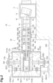
FIG. 2] FIG 2 . is a cross-sectional view of the reciprocating compressor as viewed from the side. - [
FIG. 3] FIG. 3 is a cross-sectional view of the reciprocating compressor as viewed from the front. - [
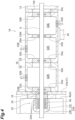
FIG. 4] FIG 4 . is an enlarged cross-sectional view of a portion ofFIG. 2 . - [
FIG. 5] FIG. 5 is a cross-sectional view illustrating a suction mechanism. - A reciprocating compressor which is an embodiment of the present disclosure includes a compression part compressing, by a piston, gas sucked into a cylinder through a suction valve, and discharging the compressed gas through a discharge valve, a piston drive part supplying a force to the piston to reciprocate the piston via a rod coupled to the piston, and a container part accommodating the compression part and forming a vacuum region around the compression part.
- In the reciprocating compressor, the compression part that compresses gas is accommodated in the container part. The container part forms a vacuum region around the compression part. As a result, the compression part is thermally insulated from the external region by the vacuum region. That is, excessive cooling of the region surrounding the reciprocating compressor is prevented even when cryogenic gas is supplied to the compression part. The generation of liquefied air can thus be suppressed.
- The container part includes a housing forming the vacuum region, and a cylinder holding part disposed between the housing and the cylinder. A side surface of the cylinder is spaced from an inner surface of the housing facing the side surface of the cylinder. A first end part of the cylinder holding part is formed on the side surface of the cylinder. A second end part of the cylinder holding part is formed on the inner surface of the housing. Such configurations enable the cylinder to be suitably supported. As a result, vibration caused by the reciprocating motion of the piston can be tolerated.
- The reciprocating compressor of one embodiment may further include an intermediate tube part disposed between the piston drive part and the container part, and accommodating the rod, and a heat resistive part disposed between the compression part and the intermediate tube part. Such configurations enable the intermediate tube part to be thermally insulated from the compression part. As a result, the influence of the heat of the compression part on the intermediate tube part can be suppressed even when cryogenic gas is supplied to the compression part. That is, excessive cooling of the intermediate tube part is prevented even when cryogenic gas is supplied to the compression part.
- In one embodiment, the suction valve may be formed in the cylinder, and may be capable of alternately switching between an open mode allowing entry and exit of the gas to and from the cylinder and a closed mode inhibiting the entry and exit of the gas according to an internal pressure of the cylinder, and the reciprocating compressor may further include an unloader disposed on an outer surface side of the container part, and configured to force the closed mode of the suction valve to be switched to the open mode by receiving a supply of compressed gas. The unloader is disposed outside the container part. The outside of the container part is thermally insulated from the compression part. The unloader is thus not affected by the heat of the compression part. As a result, the unloader is capable of operating reliably.
- The reciprocating compressor of one embodiment may further include an intermediate tube part disposed between the piston drive part and the container part, and accommodating the rod. The intermediate tube part may form a first intermediate chamber, a second intermediate chamber, and a third intermediate chamber. The first intermediate chamber, the second intermediate chamber, and the third intermediate chamber may be disposed in the order of the first intermediate chamber, the second intermediate chamber, and the third intermediate chamber in a direction from the piston drive part toward the container part. An internal pressure of the first intermediate chamber may be higher than internal pressures of the second intermediate chamber and the third intermediate chamber. According to these configurations, the first intermediate chamber, the second intermediate chamber, and the third intermediate chamber are formed between the compression part and the piston drive part. The internal pressure of the first intermediate chamber formed closer to the piston drive part is higher than the internal pressures of the second intermediate chamber and the third intermediate chamber. As a result, leakage of gas from the compression part to the piston drive part can be suppressed by this pressure difference. The leakage of cryogenic gas is thus suppressed. As a result, the piston drive part can be reliably operated.
- In one embodiment, a liquefaction temperature of the gas may be lower than the liquefaction temperature of oxygen or the liquefaction temperature of nitrogen. The reciprocating compressor of the one embodiment may be suitably applied to such gas.
- Embodiments for implementing the reciprocating compressor of the present disclosure will be described below with reference to the accompanying drawings. Like elements are given like reference signs in the description of the drawings and redundant explanation is omitted.
-
FIG. 1 illustrates a boil-off gas compression system that hasreciprocating compressors BOG compression system 100" in the description below. TheBOG compression system 100 is installed in a receiving terminal, a storage terminal, and the like for hydrogen. A storage terminal is equipped with tanks that store liquid hydrogen. Hydrogen gas is generated inside the tanks by the vaporization of the liquid hydrogen. TheBOG compression system 100 is used to compress the hydrogen gas. - A case in which the
BOG compression system 100 is intended for hydrogen gas is described below as an example. However, the gas for which theBOG compression system 100 is intended is not limited to hydrogen gas. TheBOG compression system 100 is also applicable to gas fuel such as natural gas or propane gas. That is, theBOG compression system 100 is applicable to systems that generate BOG. Specifically, theBOG compression system 100 can be suitably used for systems intended for gas having a liquefaction temperature that is lower than the liquefaction temperature of air. Air contains mainly oxygen and nitrogen. TheBOG compression system 100 can thus be suitably used for systems intended for gas having a liquefaction temperature that is lower than the liquefaction temperature of oxygen or the liquefaction temperature of nitrogen. Such gas includes hydrogen mentioned above and helium. The simple term "gas" herein broadly refers to gas fuel including natural gas and the like. The term "gas" also narrowly refers to hydrogen gas and the like which have a liquefaction temperature that is lower than the liquefaction temperature of air among gas fuels. - The
BOG compression system 100 has the tworeciprocating compressors reciprocating compressor 1A, for example, sucks in hydrogen gas from a tank. Thereciprocating compressor 1A then compresses the sucked hydrogen gas. Thereciprocating compressor 1A then supplies the compressed hydrogen gas to theother reciprocating compressor 1B. Theother reciprocating compressor 1B further compresses the hydrogen gas and then discharges the same. That is, theBOG compression system 100 is a two-stage compression system in which gas compressed by the onereciprocating compressor 1A is further compressed by theother reciprocating compressor 1B. Thereciprocating compressors compression parts 2 and apiston drive part 3. It should be noted that the number of reciprocating compressors that theBOG compression system 100 has may be selected as appropriate according to the performance required of theBOG compression system 100. For example, theBOG compression system 100 may be a three-stage system having three reciprocating compressors, or a four-stage system having four reciprocating compressors. Additionally, for example, theBOG compression system 100 may be a three-stage system having four reciprocating compressors. - The
reciprocating compressors reciprocating compressor 1A (left side of the page) will be described in detail below, and the description of theother reciprocating compressor 1B (right side of the page) is omitted. - The
compression part 2 has acylinder 4, apiston 6, asuction mechanism 7, and adischarge mechanism 8. Thecylinder 4 and thepiston 6 form compression spaces P1, P2 that compress gas. For example, thecompression part 2 has two of the compression spaces P1, P2. Thesuction mechanism 7 and thedischarge mechanism 8 are formed to be able to suck and discharge gas into and from the compression spaces P1, P2. Thepiston 6 has an end part of apiston rod 9 coupled thereto. The other end part of thepiston rod 9 is coupled to thepiston drive part 3. - The
piston drive part 3 has acrank shaft 11. Thecrank shaft 11 converts rotational motion provided by adrive source 12 into reciprocating motion of thepiston rod 9. In addition to thecrank shaft 11, thepiston drive part 3 has acrank case 13, acrosshead 14, and a connectingrod 16. - As illustrated in
FIG. 2 , in addition to thecompression part 2 and thepiston drive part 3, thereciprocating compressor 1A further has acontainer part 15, anintermediate tube part 18, and ahousing heat insulator 19. - The shape of the
cylinder 4 of thecompression part 2 may be selected as appropriate according to the required performance or condition. For example, thecylinder 4 may have a rectangular cuboid or cylindrical shape. The present disclosure is described with thecylinder 4 having a rectangular cuboid shape. Thecylinder 4 is disposed such that the central axis of thecylinder 4 extends along the horizontal direction. A cylinderdistal end part 4a has an opening. The opening is closed in an airtight manner by alid 4H. Thelid 4H may have a clearance valve. A cylinderbase end part 4b is fixed to thecontainer part 15. More specifically, the housing heat insulator 19 (heat resistive part) is inserted between the cylinderbase end part 4b and thecontainer part 15. Thehousing heat insulator 19 suppresses heat transfer between thecylinder 4 and thecontainer part 15. For example, a heat insulating fiber-reinforced resin such as a glass fiber-reinforced resin may be used as thehousing heat insulator 19. - The
container part 15 has ahousing 17 and acylinder support 21. Thehousing 17 forms a receiving space S that accommodates thecompression part 2. The pressure of the receiving space S is reduced, and is in a so-called vacuum state. A vacuum pump not shown is connected to thecontainer part 15. The vacuum pump is operated as necessary during the operation of thereciprocating compressor 1A. The vacuuming action of the vacuum pump may be continuous or intermittent. A vacuum state means that the internal pressure of thehousing 17 is lower than the atmospheric pressure. That is, there are no limits on the specific value of the internal pressure or the specific degree of vacuum in defining the vacuum state. The receiving space S formed by thehousing 17 thermally insulates thecompression part 2 from the atmospheric environment. Thehousing 17 thus forms an insulating part around thecompression part 2. That is, the vacuum state of the receiving space S is a state in which a desired insulating effect can be exhibited. - It should be noted that the present disclosure gives an example of a configuration in which the
reciprocating compressors container part 15. For example, it is not necessary for all of thereciprocating compressors BOG compression system 100 to have thecontainer part 15. For example, in theBOG compression system 100, thecontainer part 15 of thereciprocating compressor 1B may be omitted with only the firststage reciprocating compressor 1A having thecontainer part 15. - The shape of the
housing 17 is, for example, cylindrical. Thehousing 17 has a housingdistal end part 17a, a housingbase end part 17b, and ahousing circumferential wall 17c. The space surrounded by the housingdistal end part 17a, the housingbase end part 17b, and thehousing circumferential wall 17c is the receiving space S. The housingbase end part 17b is fixed to thecylinder 4 via thehousing heat insulator 19. The length of thehousing 17 in the axial direction is longer than the length of thecylinder 4 in the axial direction. A gap is thus formed between the housingdistal end part 17a and the cylinderdistal end part 4a. The diameter of thehousing 17 is greater than the height and width of thecylinder 4. Additionally, the central axis of thecylinder 4 roughly overlaps the central axis of thehousing 17. A gap is thus also formed between thehousing circumferential wall 17c and a cylinderupper surface 4c. Similarly, a gap is also formed between thehousing circumferential wall 17c and a cylinderlower surface 4d. These gaps are vacuum regions formed around thecylinder 4. - The cylinder
base end part 4b is fixed to thehousing 17. The cylinderdistal end part 4a, the cylinderupper surface 4c, and the cylinderlower surface 4d are thus spaced from thehousing 17. This is a cantilevered state with the cylinderbase end part 4b being a support end. As such, a distal end side of thecylinder 4 is supported by thecylinder support 21. - The
cylinder support 21 is disposed at a distal end part of thecylinder 4. Thecylinder support 21 supports the distal end part of thecylinder 4 in the vertical direction. Thecylinder support 21 has anexternal container support 26, a lowerinternal container support 27A, and an upperinternal container support 27B. Theexternal container support 26, the lowerinternal container support 27A, and the upperinternal container support 27B are disposed on the same reference line that extends along the vertical direction. It should be noted that "disposed on the same reference line" is not limited to a configuration in which axes of theexternal container support 26, the lowerinternal container support 27A, and the upperinternal container support 27B exactly match a common reference axis. It is only required that theexternal container support 26, the lowerinternal container support 27A, and the upperinternal container support 27B are disposed to be able to suitably transmit the weight of thecylinder 4 to abase 200. - The
external container support 26 is disposed outside thehousing 17. More specifically, theexternal container support 26 is disposed between an outer circumferential surface of thehousing circumferential wall 17c and thebase 200. In other words, an upper end of theexternal container support 26 is fixed to the outer circumferential surface of thehousing circumferential wall 17c. A lower end of theexternal container support 26 is fixed to thebase 200. - The lower
internal container support 27A is disposed inside thehousing 17. More specifically, the lowerinternal container support 27A is disposed between an inner circumferential surface of thehousing circumferential wall 17c and the cylinderlower surface 4d. The lowerinternal container support 27A is disposed on theexternal container support 26 with thehousing circumferential wall 17c interposed therebetween. According to this structure, the weight of thecompression part 2 is transmitted to thebase 200 via the lowerinternal container support 27A, thehousing circumferential wall 17c, and theexternal container support 26. - As illustrated in
FIG. 3 , the lowerinternal container support 27A has an outer circumferential pedestal 28 (second end part), an inner circumferential pedestal 29 (first end part), and anelastic part 31. The outercircumferential pedestal 28 is fixed to the inner circumferential surface of thehousing circumferential wall 17c. The innercircumferential pedestal 29 is fixed to the cylinderlower surface 4d. Theelastic part 31 is inserted between the outercircumferential pedestal 28 and the innercircumferential pedestal 29. Theelastic part 31 allows the movement of the innercircumferential pedestal 29 relative to the outercircumferential pedestal 28. For example, theelastic part 31 allows the movement of the innercircumferential pedestal 29 in a perpendicular direction relative to the outercircumferential pedestal 28. - The inner
circumferential pedestal 29 has apedestal base part 32 and apedestal coupling part 33. Thepedestal base part 32 is fixed to the cylinderlower surface 4d. Thepedestal coupling part 33 is fixed to theelastic part 31. At least one of thepedestal base part 32 and thepedestal coupling part 33 may be a heat insulating member. For example, all or a portion of thepedestal coupling part 33 may be formed of a heat insulating resin material. Thepedestal base part 32 and thepedestal coupling part 33 are not fixed to each other at the connecting portion thereof. Specifically, a base partmain surface 32s of thepedestal base part 32 is in contact with a couplingmain surface 33s of thepedestal coupling part 33. The base partmain surface 32s has a triangular cross-sectional shape. A ridgeline of the base partmain surface 32s extends in a movement direction of thepiston 6. The couplingmain surface 33s has a valley-like cross-section. According to this configuration, thepedestal coupling part 33 is movable along the movement direction of thepiston 6 relative to thepedestal base part 32. - Vibration of the
pedestal base part 32 relative to thepedestal coupling part 33 is generated by the reciprocating motion of thepiston 6. The vibration can be reduced by the friction between the base partmain surface 32s and the couplingmain surface 33s. More specifically, the lowerinternal container support 27A follows the relative movement of thecylinder 4. The weight of thecylinder 4 appropriately acts on the lowerinternal container support 27A. As result, a pressing force and a frictional force are obtained. Thus, the vibration along the direction of the reciprocating motion caused by the movement of thepiston 6 is suppressed. - Furthermore, allowing this relative movement allows thermal deformation caused by a difference in temperature between the
compression part 2 and thecontainer part 15. For example, when hydrogen gas is supplied to thecompression part 2, thecylinder 4 is cooled and may shrink in the movement direction of thepiston 6. That is, the relative positional relationship between thecompression part 2 and thecontainer part 15 may change. In the lowerinternal container support 27A, thepedestal base part 32 disposed closer to thecylinder 4 is capable of moving relative to thepedestal coupling part 33 disposed closer to thehousing 17. The deformation of thecylinder 4 is thus allowed by the movement of thepedestal base part 32 relative to thepedestal coupling part 33. Consequently, thereciprocating compressor 1A is capable of reducing the generation of unwanted stress by the thermal deformation caused by the temperature difference. The thermal deformation caused by the difference in temperature between thecompression part 2 and thecontainer part 15 also causes a change in the relative positional relationship in a direction intersecting the movement direction of the piston 6 (for example, perpendicular direction). Theelastic part 31 allows the change in this direction. - It should be noted that the configuration of the
pedestal base part 32 and thepedestal coupling part 33 is not limited to that described above. More specifically, the configuration of the base partmain surface 32s and the couplingmain surface 33s is not limited to that described above. For example, the concave-convex relationship between the base part main surface and the coupling main surface may be inverted. Alternatively, the base part main surface may be a convex curved surface, and the coupling main surface may be a concave curved surface. Furthermore, the base part main surface and the coupling main surface may have a guiding structure. Specifically, the connecting portion between the pedestal base part and the pedestal coupling part may have a guiding structure that extends in the axial direction. The pedestal base part has at least one ridge. The pedestal coupling part has at least one guide groove. The cross-sectional shape of the ridge is substantially the same as the cross-sectional shape of the guide groove, and the ridge is fitted into the guide groove. The ridge is slidable in the axial direction. However, the ridge cannot move in the direction intersecting the axial direction. - The lower
internal container support 27A and theexternal container support 26 support the weight of thecompression part 2 as described above. That is, the lowerinternal container support 27A forms a cylinder holding part. The pressure inside thehousing 17 is reduced. Thus, an external force due to atmospheric pressure acts on thehousing 17. The external force, for example, acts in a direction to crush thehousing circumferential wall 17c. The upperinternal container support 27B has thus been provided, in addition to the lowerinternal container support 27A, as a member to counteract the external force. Similarly to the lowerinternal container support 27A described above, the upperinternal container support 27B also functions to suppress the vibration caused by the movement of thepiston 6 by the pressing force of an elastic body. - The upper
internal container support 27B is disposed inside thehousing 17. More specifically, the upperinternal container support 27B is disposed between the inner circumferential surface of thehousing circumferential wall 17c and the cylinderupper surface 4c. Similarly to the lowerinternal container support 27A, the upperinternal container support 27B is disposed above theexternal container support 26. It should be noted that the configuration of the upperinternal container support 27B is the same as that of the lowerinternal container support 27A. Detailed description of the upperinternal container support 27B is thus omitted. - The
compression part 2 further has a piston rod packing 22, in addition to thecylinder 4, thepiston 6, thesuction mechanism 7, and thedischarge mechanism 8. - As shown in
FIG. 4 , a portion of the piston rod packing 22 is disposed in apacking hole 4p which has an opening at the cylinderbase end part 4b. The piston rod packing 22 allows the reciprocating motion of thepiston rod 9 relative to thecylinder 4. The piston rod packing 22 also keeps the compression spaces P1, P2 airtight. The piston rod packing 22 functions as a sealing part to suppress leakage of gas from thecylinder 4. - The piston rod packing 22 has a plurality of packing
units ring 24. Each of thepacking units packing case 23h and at least onepacking ring 23r. The material, shape, and number of thepacking ring 23r may be selected as appropriate according to the required sealing property of the piston rod packing 22. For example, Teflon (Registered Trademark) may be used as the material of thepacking ring 23r. Thepacking units ring 24 in addition to thepacking units - A plurality of the
packing units 23A are disposed in thepacking hole 4p of thecylinder 4. It can be said that thepacking units 23A are disposed inside thehousing 17. "Inside thehousing 17" herein is, in other words, the part affected by the temperature of gas. That is, thepacking units 23A are exposed to a cryogenic environment. - The packing
units packing hole 4p. Thepacking unit 23B may be considered as a portion of thehousing 17. Thepacking unit 23C may be considered as a portion of theintermediate tube part 18. The packingunits housing 17. "Outside thehousing 17" herein is, in other words, the part that does not tend to be affected by the temperature of gas. That is, the packingunits - "Inside the
housing 17" and "outside thehousing 17" described above can be distinguished by the insulatingring 24. That is, thepacking unit 23A disposed "inside thehousing 17" is disposed closer to thecylinder 4 than the insulatingring 24. The packingunits housing 17" are disposed closer to theintermediate tube part 18 than the insulatingring 24. In the example illustrated inFIG. 4 , the insulatingring 24 is a portion of thehousing heat insulator 19. That is, the insulatingring 24 is disposed between the cylinderbase end part 4b and thehousing 17. It should be noted that the insulatingring 24 may be a component different from thehousing heat insulator 19. In that case, the insulatingring 24 may be disposed in thepacking hole 4p of thecylinder 4. - As illustrated in
FIG. 2 , thesuction mechanism 7 guides gas inside thecylinder 4. The gas to be sucked in is, for example, hydrogen gas at -245°C. Thesuction mechanism 7 has anexpansion joint 34, asuction valve 36, and an unloader 38 (seeFIG. 5 ). Theexpansion joint 34 is disposed between thecylinder 4 and thehousing 17. More specifically, one end of theexpansion joint 34 is connected to asuction lid 17N of thehousing 17. The other end of theexpansion joint 34 is connected to the cylinderupper surface 4c. Ahole 34h that forms a gas passage is formed inside theexpansion joint 34. Thehole 34h is connected to agas introduction hole 4n formed in thecylinder 4. Thegas introduction hole 4n is provided with thesuction valve 36. Thesuction valve 36 alternately switches between a state of allowing the suction of gas (open mode) and a state of inhibiting the suction of gas (closed mode) according to the internal pressures of the compression spaces P1, P2. - As illustrated in
FIG. 5 , thesuction valve 36 opens or closes the gas passage according to the internal pressure of thecylinder 4. Thesuction valve 36 has avalve guard 39, avalve plate 41, and avalve seat 42. Thevalve guard 39, thevalve plate 41, and thevalve seat 42 form a control valve. Thevalve plate 41 is disposed between thevalve guard 39 and thevalve seat 42, and is movable therebetween. When thevalve plate 41 is in contact with thevalve seat 42, thesuction valve 36 is in the closed mode. When thevalve plate 41 is in contact with thevalve guard 39, thesuction valve 36 is in the open mode. The open mode and the closed mode are switched according to the internal pressures of the compression spaces P1, P2. For example, thesuction valve 36 is in the open mode that allows the entry and exit of gas when the internal pressures of the compression spaces P1, P2 decrease (intake), and thesuction valve 36 is in the closed mode that inhibits the entry and exit of gas when the internal pressures of the compression spaces P1, P2 increase (compression). - As illustrated in
FIG. 2 , thedischarge mechanism 8 discharges gas from inside thecylinder 4. The gas to be discharged is, for example, hydrogen gas at -200°C. Thedischarge mechanism 8 has anexpansion joint 49 and adischarge valve 51. Theexpansion joint 49 is disposed between thecylinder 4 and thehousing 17. More specifically, one end of theexpansion joint 49 is connected to adischarge lid 17M of thehousing 17. The other end of theexpansion joint 49 is connected to the cylinderlower surface 4d. A throughhole 49h of theexpansion joint 49 is connected to agas discharge hole 4m formed in thecylinder 4. Thegas discharge hole 4m is provided with thedischarge valve 51. - The
discharge valve 51 has, similarly to thesuction valve 36, thevalve guard 39, thevalve plate 41, thevalve seat 42, and aspring 43. However, the relationship between the internal pressures of the compression spaces P1, P2 and the open and closed modes is different from that of thesuction valve 36. That is, thedischarge valve 51 is in the closed mode when the internal pressures of the compression spaces P1, P2 decrease (intake), and is in the open mode when the internal pressures of the compression spaces P1, P2 increase (compression). - The
reciprocating compressor 1A has the unloader 38 (seeFIG. 5 ) as a capacity adjusting mechanism. Theunloader 38 is attached to thesuction valve 36. - As illustrated in
FIG. 5 , theunloader 38 has ayoke bar 44, ayoke plate 46, ayoke rod 61, and arod drive part 48. A distal end of theyoke bar 44 abuts against thevalve plate 41. A base end of theyoke bar 44 is fixed to theyoke plate 46. Theyoke plate 46 is a disc, and theyoke rod 61 is fixed to the center thereof. Theyoke rod 61 is disposed such that the axis of theyoke rod 61 extends in a direction orthogonal to the reciprocating axis. A base end of theyoke rod 61 projects from thehousing circumferential wall 17c. The base end of theyoke rod 61 is accommodated in therod drive part 48. Therod drive part 48 is formed on the outer circumferential surface of thehousing circumferential wall 17c. Therod drive part 48 controls the position of theyoke rod 61. Therod drive part 48 has, for example, adiaphragm 48a. Controlling the pressure difference on opposite sides of thediaphragm 48a enables the position of theyoke rod 61 to be controlled. The pressure difference is controlled by the compressed gas supplied to one side of thediaphragm 48a. - The
yoke rod 61 has afirst rod 63, an insulatingrod 62, an isolatingpart 65, and asecond rod 64. These parts are disposed in this order from outside thehousing 17 toward thecylinder 4. An upper end of thefirst rod 63 is an upper end of theyoke rod 61. The upper end of thefirst rod 63 contacts thediaphragm 48a. A lower end of thefirst rod 63 is connected to the insulatingrod 62. The insulatingrod 62 thermally insulates thefirst rod 63 which is disposed closer to thehousing 17 from thesecond rod 64 which is disposed closer to thecylinder 4. An upper end of the insulatingrod 62 is connected to the lower end of thefirst rod 63. A lower end of the insulatingrod 62 is connected to the isolatingpart 65. The isolatingpart 65 enables thefirst rod 63 and the insulatingrod 62 to be detached from thesecond rod 64. For example, thecylinder 4 heat-shrinks when hydrogen gas is supplied to thecylinder 4. As a result, the relative distance between thecylinder 4 and thehousing 17 changes. If theyoke rod 61 were an integrated rod body, tensile stress would act on the rod body. Thus, to deal with an increase in the relative distance between thecylinder 4 and thehousing 17, the isolatingpart 65 is provided so that thefirst rod 63 and the insulatingrod 62 can be detached from thesecond rod 64. An upper part of the isolatingpart 65 is connected to the insulatingrod 62. A lower part of the isolatingpart 65 is connected to an upper end of thesecond rod 64. The upper end of thesecond rod 64 is connected to a lower end of the isolatingpart 65. A lower end of thesecond rod 64 is a lower end of theyoke rod 61, and is connected to theyoke plate 46. - As illustrated in
FIG. 4 , thesuction valve 36 closes when the internal pressures of the compression spaces P1, P2 increase (compression). When the internal pressures of the compression spaces P1, P2 increase, theunloader 38 forces the closed state to be released. Specifically, when the internal pressures of the compression spaces P1, P2 increase, thevalve plate 41 comes into contact with thevalve seat 42. Theunloader 38 releases the contact with thevalve seat 42 by pressing thevalve plate 41 when capacity control is required. As a result, gas is not compressed in thecylinder 4, so that the internal pressures do not increase. Compressed gas is not supplied since thedischarge valve 51 which opens by the increase in the internal pressures of the compression spaces P1, P2 is not opened. The capacity of thereciprocating compressor 1A can thus be adjusted. - The
intermediate tube part 18 is disposed between thehousing 17 and thepiston drive part 3. Theintermediate tube part 18 may, for example, be supported by asupport 40. Theintermediate tube part 18 accommodates thepiston rod 9. Theintermediate tube part 18 has a frontintermediate tube 52 and a rearintermediate tube 53. The frontintermediate tube 52 is disposed closer to thehousing 17. The rearintermediate tube 53 is disposed closer to thepiston drive part 3. It should be noted that, in theintermediate tube part 18, the frontintermediate tube 52 and the rearintermediate tube 53 may be integrated. The frontintermediate tube 52 is fixed to the housingbase end part 17b. The frontintermediate tube 52 is also fixed to the rearintermediate tube 53. - The front
intermediate tube 52 has ahole 52a that is formed in a front end part, and ahole 52b that is formed in a rear end part. The inner diameters of theholes piston rod 9. Thepacking unit 23C is fitted into thehole 52a. That is, thepiston rod 9 is inserted through thepacking unit 23C at a front end surface. It should be noted that desired parts such as the packing unit may also be disposed in thehole 52b. - The front
intermediate tube 52 forms arod packing chamber 52R. Therod packing chamber 52R is filled with the same type of gas as the gas supplied to thecompression part 2. For example, when the gas supplied to thecompression part 2 is hydrogen gas, therod packing chamber 52R is filled with hydrogen gas at normal temperature. The frontintermediate tube 52 also has avent 52B for controlling the pressure of therod packing chamber 52R. - The internal space of the rear
intermediate tube 53 is divided by apartition wall 53W. As a result, the rearintermediate tube 53 has a firstintermediate chamber 53E and a secondintermediate chamber 53F. The firstintermediate chamber 53E and the secondintermediate chamber 53F are aligned along the axial direction of thepiston rod 9. The firstintermediate chamber 53E is provided closer to thepiston drive part 3. The secondintermediate chamber 53F is provided closer to the frontintermediate tube 52. The rearintermediate tube 53 hasholes holes piston rod 9. Similarly to theholes holes piston rod 9. Theholes holes holes intermediate tube 52. Apacking unit 55C is fitted into thehole 53a. Apacking unit 55A is fitted into thehole 53b. Apacking unit 55B is fitted into thehole 53c. - The first
intermediate chamber 53E is filled with nitrogen gas. The firstintermediate chamber 53E receives a supply of nitrogen gas from a gas supply part for maintaining the internal pressure. For example, the nitrogen gas is supplied to the firstintermediate chamber 53E from asupply part 53S. The gas supply part performs control such that the internal pressure of the firstintermediate chamber 53E is a desired pressure. For example, if the nitrogen gas leaks from thepacking units intermediate chamber 53E. - Ideally there should be no transfer of the nitrogen gas due to the presence of the
packing unit 55A between the firstintermediate chamber 53E and the secondintermediate chamber 53F. However, thepacking unit 55A keeps both the firstintermediate chamber 53E and the secondintermediate chamber 53F airtight as well as allowing the reciprocating motion of thepiston rod 9. Thus, a small amount of the nitrogen gas may be transferred between the firstintermediate chamber 53E and the secondintermediate chamber 53F. - Thus, the internal pressure of the first
intermediate chamber 53E is, for example, set higher than the internal pressure of the secondintermediate chamber 53F. By setting the internal pressure of the firstintermediate chamber 53E higher than the internal pressure of the secondintermediate chamber 53F, the direction of travel of the nitrogen gas between the firstintermediate chamber 53E and the secondintermediate chamber 53F can be determined. That is, the transfer of the nitrogen gas can be limited to a flow from the firstintermediate chamber 53E which has a relatively higher internal pressure to the secondintermediate chamber 53F which has a relatively lower internal pressure. This configuration suppresses the transfer of cryogenic gas compressed by thecylinder 4 from the secondintermediate chamber 53F to the firstintermediate chamber 53E. Additionally, hydrogen gas may leak from therod packing chamber 52R into the secondintermediate chamber 53F. The rearintermediate tube 53 has avent 53B which discharges mixed gas containing hydrogen and nitrogen. Thevent 53B is formed in a position corresponding to the secondintermediate chamber 53F. It should be noted that the rearintermediate tube 53 may have an oil drain part which discharges oil leaked from thecrank case 13. - The
reciprocating compressor 1A described above has, as characteristic elements, thehousing 17, thecylinder support 21, thehousing heat insulator 19, theunloader 38, and theintermediate tube part 18. The operation and effects of each of the elements will be described below. - The
reciprocating compressor 1A has thecompression part 2, thepiston drive part 3, and thehousing 17. Thecompression part 2 compresses, by thepiston 6, gas sucked into thecylinder 4 through thesuction valve 36, and discharges the compressed gas through thedischarge valve 51. Thepiston drive part 3 supplies a force to thepiston 6 to reciprocate thepiston 6 via thepiston rod 9 coupled to thepiston 6. Thehousing 17 accommodates thecompression part 2, and forms a vacuum region around thecompression part 2. - In the
reciprocating compressor 1A, thecompression part 2 that compresses gas is accommodated in thehousing 17. Thehousing 17 forms a vacuum region around thecompression part 2. As a result, thecompression part 2 is thermally insulated from a region in which thereciprocating compressor 1A is disposed by the vacuum region. Thus, excessive cooling of the region in which thereciprocating compressor 1A is disposed is suppressed even when cryogenic gas is supplied to thecompression part 2. Consequently, the generation of liquefied air can be suppressed. - By accommodating the
compression part 2 in thehousing 17 which is a vacuum vessel, the operating efficiency of the compressor can be improved. - Using a vacuum vessel to thermally insulate the
compression part 2 eliminates the need to use foam heat insulation material to thermally insulate thecompression part 2. There is no foam heat insulation material with guaranteed performance at temperatures of -200°C or lower. However, a desired heat insulation performance can be obtained by thehousing 17 independent of the use temperature environment. Additionally, the external shape of thecompression part 2 is complex, so that it would be difficult to closely adhere a foam heat insulation material to the surface of thecompression part 2. However, thehousing 17 enables a heat insulating region (vacuum region) to be formed around thecompression part 2 independent of the external shape of thecompression part 2. A foam heat insulation material is also not suitable for environments in which it will be repeatedly exposed to cryogenic and normal temperatures. Furthermore, if there is a gap between the foam heat insulation material and the compression part, liquefied air may infiltrate into the gap, and the infiltrated air may evaporate. When these infiltration and evaporation are repeated, the foam heat insulation material will tend to deteriorate. It would also be necessary to remove and reinstall the foam heat insulation material when maintaining and servicing thecompression part 2. However, thehousing 17 can also be suitably applied to such problems. - The
container part 15 has thehousing 17 and the lowerinternal container support 27A. Thehousing 17 forms the vacuum region. The lowerinternal container support 27A is disposed between thehousing 17 and thecylinder 4. The innercircumferential pedestal 29 of the lowerinternal container support 27A is formed on the cylinderlower surface 4d. The outercircumferential pedestal 28 of the lowerinternal container support 27A is formed on an inner surface of thehousing 17. Such configurations enable thecylinder 4 to be suitably supported. As a result, vibration caused by the reciprocating motion of thepiston 6 can be tolerated. - The
reciprocating compressor 1A further has thehousing heat insulator 19. Thehousing heat insulator 19 is disposed between thecylinder 4 and thehousing 17. The cylinderbase end part 4b is coupled to the housingbase end part 17b. Thehousing heat insulator 19 is sandwiched between the cylinderbase end part 4b and the housingbase end part 17b. Such configurations enable thecylinder 4 to be thermally insulated from thehousing 17. As a result, the influence of the heat of thecylinder 4 on thehousing 17 can be suppressed even when cryogenic gas is supplied to thecylinder 4. Thus, excessive cooling of the region in which thereciprocating compressor 1A is disposed is further suppressed. - The
rod drive part 48 of theunloader 38 formed in thesuction valve 36 is disposed on the outer circumferential surface side of thehousing 17. According to this configuration, therod drive part 48 is disposed outside thehousing 17. The outside of thehousing 17 is thermally insulated from thecompression part 2 by the vacuum region. Theunloader 38 can thus operate reliably without being affected by the heat of thecompression part 2. Specifically, theunloader 38 receives compressed gas for driving the diaphragm. The compressed gas includes compressed air, compressed nitrogen, or the like. According to the configuration above, theunloader 38 is not affected by the heat of thecompression part 2. As a result, the compressed air does not liquefy. Consequently, theunloader 38 is capable of operating reliably. - The
reciprocating compressor 1A further has theintermediate tube part 18. Theintermediate tube part 18 is disposed between thepiston drive part 3 and thecontainer part 15. Theintermediate tube part 18 accommodates thepiston rod 9. Theintermediate tube part 18 forms the firstintermediate chamber 53E, the secondintermediate chamber 53F, and therod packing chamber 52R. The firstintermediate chamber 53E, the secondintermediate chamber 53F, and therod packing chamber 52R are disposed in the order of the firstintermediate chamber 53E, the secondintermediate chamber 53F, and therod packing chamber 52R in a direction from thepiston drive part 3 toward thehousing 17. The internal pressure of the firstintermediate chamber 53E is higher than the internal pressures of the secondintermediate chamber 53F and a third intermediate chamber. - According to these configurations, the first
intermediate chamber 53E, the secondintermediate chamber 53F, and therod packing chamber 52R are formed between thecompression part 2 and thepiston drive part 3. The internal pressure of the firstintermediate chamber 53E formed closer to thepiston drive part 3 is higher than the internal pressures of the secondintermediate chamber 53F and therod packing chamber 52R. As a result, leakage of gas from thecompression part 2 to thepiston drive part 3 can be suppressed by this pressure difference. By suppressing the leakage of cryogenic gas, thepiston drive part 3 can be reliably operated. - Additionally, three chambers are formed between the
compression part 2 and thepiston drive part 3. This configuration enables the distance from thecompression part 2 to thepiston drive part 3 to be increased. As a result, the heat of thecompression part 2 does not tend to affect thepiston drive part 3. Thus, thepiston drive part 3 can be reliably operated. - The
reciprocating compressors reciprocating compressors - For example, the
cylinder 4 of thereciprocating compressor 1A is not directly fixed to theintermediate tube part 18. Thehousing heat insulator 19 and the housingbase end part 17b of thehousing 17 are inserted between thecylinder 4 and theintermediate tube part 18. For example, thecylinder 4 of the reciprocating compressor may be fixed to theintermediate tube part 18 without thehousing 17 interposed therebetween. In this case, a heat insulator is disposed between thecylinder 4 and theintermediate tube part 18 as the heat resistive part. In other words, the heat resistive part contacts both thecylinder 4 and theintermediate tube part 18. The configuration in which the heat resistive part is disposed between thecompression part 2 and theintermediate tube part 18 may be a configuration in which only the heat resistive part is disposed between thecompression part 2 and theintermediate tube part 18. It may also be a configuration in which, similarly to the embodiments, the heat resistive part and other elements (the housingbase end part 17b of the housing 17) are inserted between thecompression part 2 and theintermediate tube part 18. - A configuration in which nitrogen gas is supplied to the first
intermediate chamber 53E has been described as an example of a configuration in which the direction of travel of gas in theintermediate tube part 18 is restricted. The configuration in which the direction of travel of gas is restricted is not limited to this configuration. The configuration in which the direction of travel of gas is restricted may employ, as appropriate, a configuration in which the direction of travel of nitrogen gas can be restricted by managing pressure. For example, a configuration of supplying nitrogen gas to thepacking unit 55A may be employed instead of the configuration of supplying nitrogen gas to the firstintermediate chamber 53E. In this configuration, the pressure of the nitrogen gas supplied to thepacking unit 55A is also set higher than the internal pressure of the secondintermediate chamber 53F. - The
diaphragm 48a driven by compressed gas has been described above as an example of a drive mechanism of theunloader 38. The drive mechanism of theunloader 38 is not limited to this configuration. For example, an air cylinder driven by compressed gas may be provided as the drive mechanism of theunloader 38 instead of thediaphragm 48a. -
- 1A, 1B
- Reciprocating compressor
- 2
- Compression part
- 3
- Piston drive part
- 4
- Cylinder
- 6
- Piston
- 7
- Suction mechanism
- 8
- Discharge mechanism
- 9
- Piston rod
- 11
- Crank shaft
- 12
- Drive source
- 13
- Crank case
- 14
- Crosshead
- 15
- Container part
- 16
- Connecting rod
- 17
- Housing
- 17N
- Suction lid
- 17M
- Discharge lid
- 18
- Intermediate tube part
- 19
- Housing heat insulator
- 21
- Cylinder support
- 22
- Piston rod packing
- 23A, 23B, 23C
- Packing unit
- 24
- Insulating ring
- 26
- External container support
- 27A
- Lower internal container support
- 27B
- Upper internal container support
- 28
- Outer circumferential pedestal
- 29
- Inner circumferential pedestal
- 31
- Elastic part
- 32
- Pedestal base part
- 33
- Pedestal coupling part
- 34
- Expansion joint
- 36
- Suction valve
- 38
- Unloader
- 48
- Rod drive part
- 49
- Expansion joint
- 51
- Discharge valve
- 52
- Front intermediate tube
- 52B, 53B
- Vent
- 52R
- Rod packing chamber
- 53
- Rear intermediate tube
- 53S
- Supply part
- 53W
- Partition wall
- 61
- Yoke rod
- 100
- BOG compression system
- 200
- Base
- P1, P2
- Compression space
- S
- Receiving space
Claims (4)
- A reciprocating compressor (1A, 1B) comprising:a compression part (2) compressing, by a piston (6), gas sucked into a cylinder (4) through a suction valve (7), and discharging the compressed gas through a discharge valve (8);a piston drive part supplying a force to the piston (6) to reciprocate the piston (6) via a rod (9) coupled to the piston (6); anda container part (15) accommodating the compression part (2) and forming a vacuum region around the compression part (2), whereinthe container part (15) includes a housing (17) forming the vacuum region, and a cylinder holding part disposed between the housing (17) and the cylinder (4),a side surface of the cylinder (4) is spaced from an inner surface of the housing (17) facing the side surface of the cylinder (4),a first end part of the cylinder holding part is formed on the side surface of the cylinder (4),a second end part of the cylinder holding part is formed on the inner surface of the housing (17), characterized in thatthe first end part includes a pedestal base part (32) fixed to the side surface of the cylinder (4), and a pedestal coupling part (33) in contact with the pedestal base part (32) and coupled to the second end part via an elastic part 31, andthe pedestal coupling part (33) is movable relative to the pedestal base part (32) along a movement direction of the piston (6).
- The reciprocating compressor according to claim 1, further comprising:an intermediate tube part disposed between the piston drive part and the container part (15), and accommodating the rod (9); anda heat resistive part disposed between the compression part (2) and the intermediate tube part.
- The reciprocating compressor (1A, 1B) according to claim 1,wherein the suction valve (7) is formed in the cylinder (4), and is capable of alternately switching between an open mode allowing entry and exit of the gas to and from the cylinder (4) and a closed mode inhibiting the entry and exit of the gas according to an internal pressure of the cylinder (4), andthe reciprocating compressor (1A, 1B) further includes an unloader (38) disposed on an outer surface side of the container part (15), and configured to force the closed mode of the suction valve to be switched to the open mode by receiving a supply of compressed gas.
- The reciprocating compressor (1A, 1B) according to claim 1, further comprising an intermediate tube part disposed between the piston drive part and the container part (15), and accommodating the rod (9),wherein the intermediate tube part forms a first intermediate chamber, a second intermediate chamber, and a third intermediate chamber,the first intermediate chamber, the second intermediate chamber, and the third intermediate chamber are disposed in the order of the first intermediate chamber, the second intermediate chamber, and the third intermediate chamber in a direction from the piston drive part toward the container part (15), andan internal pressure of the first intermediate chamber is higher than internal pressures of the second intermediate chamber and the third intermediate chamber.
Applications Claiming Priority (2)
| Application Number | Priority Date | Filing Date | Title |
|---|---|---|---|
| JP2019074035A JP6781795B2 (en) | 2019-04-09 | 2019-04-09 | Reciprocating compressor |
| PCT/JP2020/005190 WO2020208930A1 (en) | 2019-04-09 | 2020-02-10 | Reciprocating compressor |
Publications (3)
| Publication Number | Publication Date |
|---|---|
| EP3951178A1 EP3951178A1 (en) | 2022-02-09 |
| EP3951178A4 EP3951178A4 (en) | 2022-12-14 |
| EP3951178B1 true EP3951178B1 (en) | 2025-03-19 |
Family
ID=72751015
Family Applications (1)
| Application Number | Title | Priority Date | Filing Date |
|---|---|---|---|
| EP20788582.3A Active EP3951178B1 (en) | 2019-04-09 | 2020-02-10 | Reciprocating compressor |
Country Status (8)
| Country | Link |
|---|---|
| US (1) | US12037994B2 (en) |
| EP (1) | EP3951178B1 (en) |
| JP (1) | JP6781795B2 (en) |
| KR (1) | KR102588560B1 (en) |
| CN (1) | CN113677891B (en) |
| ES (1) | ES3017416T3 (en) |
| SG (1) | SG11202111167SA (en) |
| WO (1) | WO2020208930A1 (en) |
Families Citing this family (14)
| Publication number | Priority date | Publication date | Assignee | Title |
|---|---|---|---|---|
| FR3123094B1 (en) * | 2021-05-21 | 2023-12-08 | Air Liquide | Compression apparatus and filling station comprising such apparatus. |
| IT202100019502A1 (en) * | 2021-07-22 | 2023-01-22 | Nuovo Pignone Tecnologie Srl | A RECIPROCATING COMPRESSOR WITH PRESSURE REDUCING CHAMBER AND METHOD |
| CN114215725B (en) * | 2021-12-14 | 2023-08-04 | 西安交通大学 | A Two-Stage Compression Diaphragm Compressor System |
| JP7623981B2 (en) | 2022-06-02 | 2025-01-29 | 株式会社神戸製鋼所 | Compressor Unit |
| JP7695223B2 (en) * | 2022-11-11 | 2025-06-18 | 株式会社神戸製鋼所 | Reciprocating compressor unit and method of operating the compressor unit |
| JP2024098377A (en) * | 2023-01-10 | 2024-07-23 | 川崎重工業株式会社 | Hydrogen gas transport device and compressor purging method |
| KR20250110289A (en) | 2023-01-12 | 2025-07-18 | 가부시키가이샤 고베 세이코쇼 | Compressor unit |
| JP7733029B2 (en) | 2023-02-13 | 2025-09-02 | 株式会社神戸製鋼所 | Compressor Unit |
| JP7695278B2 (en) | 2023-02-15 | 2025-06-18 | 株式会社神戸製鋼所 | Compressor Unit |
| CN116906320B (en) * | 2023-08-08 | 2025-12-26 | 成都理工大学 | A liquid compression machine |
| JP7758709B2 (en) * | 2023-08-22 | 2025-10-22 | 株式会社神戸製鋼所 | Compressor Unit |
| JP7836791B2 (en) * | 2023-08-28 | 2026-03-27 | 株式会社神戸製鋼所 | Compressor unit and method for controlling the compressor unit |
| US20250290497A1 (en) * | 2024-03-18 | 2025-09-18 | Haskel International, Llc | Conduit system for booster pump |
| EP4644694A1 (en) * | 2024-05-03 | 2025-11-05 | Arizaga Bastarrica y Compañia SA | Reciprocating compressor with gas recirculation from leak to aspiration and method for operating said compressor |
Family Cites Families (26)
| Publication number | Priority date | Publication date | Assignee | Title |
|---|---|---|---|---|
| US1878731A (en) * | 1930-08-28 | 1932-09-20 | Thompson Paul Wheeler | Method of and means for sealing the shaft packings of turbines |
| US2204374A (en) * | 1938-06-04 | 1940-06-11 | Ingersoll Rand Co | Compressor |
| US2621087A (en) * | 1950-04-20 | 1952-12-09 | Dresser Operations Inc | Rotating shaft seal means |
| US2831325A (en) * | 1955-04-28 | 1958-04-22 | Herrick L Johnston Inc | Pump for liquefied gases |
| US3220202A (en) * | 1964-05-15 | 1965-11-30 | Union Carbide Corp | Apparatus for storing and pumping a volatile liquid |
| US3632235A (en) * | 1969-06-09 | 1972-01-04 | Carl A Grenci | Cryogenic pump system |
| US4396362A (en) * | 1980-10-31 | 1983-08-02 | Union Carbide Corporation | Cryogenic reciprocating pump |
| DE3621727A1 (en) * | 1986-06-28 | 1988-01-14 | Deutsche Forsch Luft Raumfahrt | PISTON PUMP FOR CRYOGENIC LIQUIDS |
| US5246355A (en) * | 1992-07-10 | 1993-09-21 | Special Projects Manufacturing, Inc. | Well service pumping assembly |
| FR2706540B1 (en) * | 1993-06-11 | 1995-09-01 | Europ Propulsion | Removable and self-cooled integrated cryogenic liquid pump. |
| US5511955A (en) | 1995-02-07 | 1996-04-30 | Cryogenic Group, Inc. | Cryogenic pump |
| EP1616098A4 (en) * | 2003-04-22 | 2011-04-27 | Conrader R Co | Air compressor with inlet control mechanism and automatic inlet control mechanism |
| US20090165640A1 (en) * | 2004-06-30 | 2009-07-02 | Shuichi Kawasaki | Booster pump and low-temperature-fluid storage tank having the same |
| JP5107389B2 (en) | 2005-01-07 | 2012-12-26 | 三菱重工業株式会社 | Booster for cryogenic fluid |
| JP4962853B2 (en) | 2007-03-22 | 2012-06-27 | 株式会社Ihi | BOG compression equipment and method |
| KR100981048B1 (en) * | 2008-09-09 | 2010-09-10 | 두산중공업 주식회사 | Cryogenic Fluid Circulation Pump |
| JP2013068114A (en) * | 2011-09-21 | 2013-04-18 | Japan Steel Works Ltd:The | Reciprocating compressor |
| KR101687450B1 (en) * | 2014-06-24 | 2016-12-16 | 협성철광 주식회사 | High pressure pump for feeding LNG |
| CN106715906B (en) * | 2014-09-22 | 2019-06-07 | 伊格尔工业股份有限公司 | liquid supply system |
| US9995290B2 (en) * | 2014-11-24 | 2018-06-12 | Caterpillar Inc. | Cryogenic pump with insulating arrangement |
| CN204827851U (en) * | 2015-04-15 | 2015-12-02 | 蔚蓝天空科技(北京)有限公司 | Energy -conserving auxiliary device of vacuum pump |
| JP6584175B2 (en) * | 2015-07-07 | 2019-10-02 | 株式会社前川製作所 | Cryogenic liquid pump |
| DE202017106422U1 (en) | 2016-10-31 | 2018-01-22 | Trane International Inc. | Leak detection in a fluid compression system |
| CN207004829U (en) * | 2017-07-31 | 2018-02-13 | 广东美芝制冷设备有限公司 | The housing unit and compressor of compressor |
| US20190186478A1 (en) * | 2017-12-19 | 2019-06-20 | Nuovo Pignone Tecnologie - S.R.L. | Reciprocating compressor and manufacturing method |
| FR3090756B1 (en) * | 2018-12-19 | 2021-04-09 | Air Liquide | Pumping device, installation and method of supplying liquid hydrogen |
-
2019
- 2019-04-09 JP JP2019074035A patent/JP6781795B2/en active Active
-
2020
- 2020-02-10 ES ES20788582T patent/ES3017416T3/en active Active
- 2020-02-10 CN CN202080026393.7A patent/CN113677891B/en active Active
- 2020-02-10 KR KR1020217033041A patent/KR102588560B1/en active Active
- 2020-02-10 US US17/602,067 patent/US12037994B2/en active Active
- 2020-02-10 SG SG11202111167SA patent/SG11202111167SA/en unknown
- 2020-02-10 WO PCT/JP2020/005190 patent/WO2020208930A1/en not_active Ceased
- 2020-02-10 EP EP20788582.3A patent/EP3951178B1/en active Active
Also Published As
| Publication number | Publication date |
|---|---|
| ES3017416T3 (en) | 2025-05-12 |
| JP2020172870A (en) | 2020-10-22 |
| KR102588560B1 (en) | 2023-10-12 |
| JP6781795B2 (en) | 2020-11-04 |
| WO2020208930A1 (en) | 2020-10-15 |
| SG11202111167SA (en) | 2021-11-29 |
| CN113677891A (en) | 2021-11-19 |
| US20220178360A1 (en) | 2022-06-09 |
| US12037994B2 (en) | 2024-07-16 |
| EP3951178A4 (en) | 2022-12-14 |
| CN113677891B (en) | 2023-06-02 |
| EP3951178A1 (en) | 2022-02-09 |
| KR20210136120A (en) | 2021-11-16 |
Similar Documents
| Publication | Publication Date | Title |
|---|---|---|
| US12037994B2 (en) | Reciprocating compressor | |
| CN100429453C (en) | Apparatus and method for holding and removing cryogenic fluids from with reduced heat leak | |
| US5379600A (en) | Superconducting magnet and method for assembling the same | |
| US9765762B2 (en) | Cryogenic pumps | |
| KR101885017B1 (en) | Liquid supply system | |
| KR102334465B1 (en) | Cryogenic storage vessel comprising a receptacle for receiving a pump assembly | |
| EP2687793B1 (en) | Liquid supply system | |
| US20120060519A1 (en) | Cryopump and cryogenic refrigerator | |
| KR20220140832A (en) | Compression devices and charging stations comprising such devices | |
| US20120312032A1 (en) | Cryopump and cryogenic refrigerator | |
| US20170097119A1 (en) | Cryogenic tank with internal heat exchanger and fail-closed valve | |
| CN113375359B (en) | Cryogenic refrigerator and cryogenic system | |
| KR20210131238A (en) | Compression apparatus and filling station comprising such an apparatus | |
| JP7733270B2 (en) | Reciprocating compressor unit and compressor unit operating method | |
| GB2292597A (en) | Cryostat for cooling a superconducting magnet | |
| EP1869322B1 (en) | Oil-less compressor with seal-dust protection | |
| KR102867237B1 (en) | Liquefied gas storage device and operating method thereof | |
| AU2024326557A1 (en) | Compressor unit |
Legal Events
| Date | Code | Title | Description |
|---|---|---|---|
| STAA | Information on the status of an ep patent application or granted ep patent |
Free format text: STATUS: THE INTERNATIONAL PUBLICATION HAS BEEN MADE |
|
| PUAI | Public reference made under article 153(3) epc to a published international application that has entered the european phase |
Free format text: ORIGINAL CODE: 0009012 |
|
| STAA | Information on the status of an ep patent application or granted ep patent |
Free format text: STATUS: REQUEST FOR EXAMINATION WAS MADE |
|
| 17P | Request for examination filed |
Effective date: 20211102 |
|
| AK | Designated contracting states |
Kind code of ref document: A1 Designated state(s): AL AT BE BG CH CY CZ DE DK EE ES FI FR GB GR HR HU IE IS IT LI LT LU LV MC MK MT NL NO PL PT RO RS SE SI SK SM TR |
|
| DAV | Request for validation of the european patent (deleted) | ||
| DAX | Request for extension of the european patent (deleted) | ||
| A4 | Supplementary search report drawn up and despatched |
Effective date: 20221116 |
|
| RIC1 | Information provided on ipc code assigned before grant |
Ipc: F04B 53/14 20060101ALI20221110BHEP Ipc: F04B 53/08 20060101ALI20221110BHEP Ipc: F04B 53/02 20060101ALI20221110BHEP Ipc: F04B 27/04 20060101ALI20221110BHEP Ipc: F04B 27/02 20060101ALI20221110BHEP Ipc: F04B 15/08 20060101ALI20221110BHEP Ipc: F04B 5/02 20060101ALI20221110BHEP Ipc: F04B 39/12 20060101ALI20221110BHEP Ipc: F04B 39/06 20060101AFI20221110BHEP |
|
| GRAP | Despatch of communication of intention to grant a patent |
Free format text: ORIGINAL CODE: EPIDOSNIGR1 |
|
| STAA | Information on the status of an ep patent application or granted ep patent |
Free format text: STATUS: GRANT OF PATENT IS INTENDED |
|
| INTG | Intention to grant announced |
Effective date: 20241011 |
|
| GRAS | Grant fee paid |
Free format text: ORIGINAL CODE: EPIDOSNIGR3 |
|
| GRAA | (expected) grant |
Free format text: ORIGINAL CODE: 0009210 |
|
| STAA | Information on the status of an ep patent application or granted ep patent |
Free format text: STATUS: THE PATENT HAS BEEN GRANTED |
|
| AK | Designated contracting states |
Kind code of ref document: B1 Designated state(s): AL AT BE BG CH CY CZ DE DK EE ES FI FR GB GR HR HU IE IS IT LI LT LU LV MC MK MT NL NO PL PT RO RS SE SI SK SM TR |
|
| REG | Reference to a national code |
Ref country code: GB Ref legal event code: FG4D |
|
| REG | Reference to a national code |
Ref country code: CH Ref legal event code: EP |
|
| REG | Reference to a national code |
Ref country code: DE Ref legal event code: R096 Ref document number: 602020047987 Country of ref document: DE |
|
| REG | Reference to a national code |
Ref country code: IE Ref legal event code: FG4D |
|
| REG | Reference to a national code |
Ref country code: ES Ref legal event code: FG2A Ref document number: 3017416 Country of ref document: ES Kind code of ref document: T3 Effective date: 20250512 |
|
| REG | Reference to a national code |
Ref country code: NL Ref legal event code: FP |
|
| PG25 | Lapsed in a contracting state [announced via postgrant information from national office to epo] |
Ref country code: RS Free format text: LAPSE BECAUSE OF FAILURE TO SUBMIT A TRANSLATION OF THE DESCRIPTION OR TO PAY THE FEE WITHIN THE PRESCRIBED TIME-LIMIT Effective date: 20250619 |
|
| PG25 | Lapsed in a contracting state [announced via postgrant information from national office to epo] |
Ref country code: FI Free format text: LAPSE BECAUSE OF FAILURE TO SUBMIT A TRANSLATION OF THE DESCRIPTION OR TO PAY THE FEE WITHIN THE PRESCRIBED TIME-LIMIT Effective date: 20250319 |
|
| REG | Reference to a national code |
Ref country code: LT Ref legal event code: MG9D |
|
| PG25 | Lapsed in a contracting state [announced via postgrant information from national office to epo] |
Ref country code: NO Free format text: LAPSE BECAUSE OF FAILURE TO SUBMIT A TRANSLATION OF THE DESCRIPTION OR TO PAY THE FEE WITHIN THE PRESCRIBED TIME-LIMIT Effective date: 20250619 |
|
| PG25 | Lapsed in a contracting state [announced via postgrant information from national office to epo] |
Ref country code: HR Free format text: LAPSE BECAUSE OF FAILURE TO SUBMIT A TRANSLATION OF THE DESCRIPTION OR TO PAY THE FEE WITHIN THE PRESCRIBED TIME-LIMIT Effective date: 20250319 |
|
| PG25 | Lapsed in a contracting state [announced via postgrant information from national office to epo] |
Ref country code: LV Free format text: LAPSE BECAUSE OF FAILURE TO SUBMIT A TRANSLATION OF THE DESCRIPTION OR TO PAY THE FEE WITHIN THE PRESCRIBED TIME-LIMIT Effective date: 20250319 |
|
| PG25 | Lapsed in a contracting state [announced via postgrant information from national office to epo] |
Ref country code: GR Free format text: LAPSE BECAUSE OF FAILURE TO SUBMIT A TRANSLATION OF THE DESCRIPTION OR TO PAY THE FEE WITHIN THE PRESCRIBED TIME-LIMIT Effective date: 20250620 Ref country code: BG Free format text: LAPSE BECAUSE OF FAILURE TO SUBMIT A TRANSLATION OF THE DESCRIPTION OR TO PAY THE FEE WITHIN THE PRESCRIBED TIME-LIMIT Effective date: 20250319 |
|
| PG25 | Lapsed in a contracting state [announced via postgrant information from national office to epo] |
Ref country code: SE Free format text: LAPSE BECAUSE OF FAILURE TO SUBMIT A TRANSLATION OF THE DESCRIPTION OR TO PAY THE FEE WITHIN THE PRESCRIBED TIME-LIMIT Effective date: 20250319 |
|
| PG25 | Lapsed in a contracting state [announced via postgrant information from national office to epo] |
Ref country code: SM Free format text: LAPSE BECAUSE OF FAILURE TO SUBMIT A TRANSLATION OF THE DESCRIPTION OR TO PAY THE FEE WITHIN THE PRESCRIBED TIME-LIMIT Effective date: 20250319 |
|
| PG25 | Lapsed in a contracting state [announced via postgrant information from national office to epo] |
Ref country code: PT Free format text: LAPSE BECAUSE OF FAILURE TO SUBMIT A TRANSLATION OF THE DESCRIPTION OR TO PAY THE FEE WITHIN THE PRESCRIBED TIME-LIMIT Effective date: 20250721 |
|
| PG25 | Lapsed in a contracting state [announced via postgrant information from national office to epo] |
Ref country code: PL Free format text: LAPSE BECAUSE OF FAILURE TO SUBMIT A TRANSLATION OF THE DESCRIPTION OR TO PAY THE FEE WITHIN THE PRESCRIBED TIME-LIMIT Effective date: 20250319 |
|
| PG25 | Lapsed in a contracting state [announced via postgrant information from national office to epo] |
Ref country code: EE Free format text: LAPSE BECAUSE OF FAILURE TO SUBMIT A TRANSLATION OF THE DESCRIPTION OR TO PAY THE FEE WITHIN THE PRESCRIBED TIME-LIMIT Effective date: 20250319 Ref country code: CZ Free format text: LAPSE BECAUSE OF FAILURE TO SUBMIT A TRANSLATION OF THE DESCRIPTION OR TO PAY THE FEE WITHIN THE PRESCRIBED TIME-LIMIT Effective date: 20250319 |
|
| PG25 | Lapsed in a contracting state [announced via postgrant information from national office to epo] |
Ref country code: RO Free format text: LAPSE BECAUSE OF FAILURE TO SUBMIT A TRANSLATION OF THE DESCRIPTION OR TO PAY THE FEE WITHIN THE PRESCRIBED TIME-LIMIT Effective date: 20250319 |
|
| PG25 | Lapsed in a contracting state [announced via postgrant information from national office to epo] |
Ref country code: SK Free format text: LAPSE BECAUSE OF FAILURE TO SUBMIT A TRANSLATION OF THE DESCRIPTION OR TO PAY THE FEE WITHIN THE PRESCRIBED TIME-LIMIT Effective date: 20250319 |
|
| PG25 | Lapsed in a contracting state [announced via postgrant information from national office to epo] |
Ref country code: IS Free format text: LAPSE BECAUSE OF FAILURE TO SUBMIT A TRANSLATION OF THE DESCRIPTION OR TO PAY THE FEE WITHIN THE PRESCRIBED TIME-LIMIT Effective date: 20250719 |
|
| REG | Reference to a national code |
Ref country code: DE Ref legal event code: R097 Ref document number: 602020047987 Country of ref document: DE |
|
| PG25 | Lapsed in a contracting state [announced via postgrant information from national office to epo] |
Ref country code: DK Free format text: LAPSE BECAUSE OF FAILURE TO SUBMIT A TRANSLATION OF THE DESCRIPTION OR TO PAY THE FEE WITHIN THE PRESCRIBED TIME-LIMIT Effective date: 20250319 |
|
| PGFP | Annual fee paid to national office [announced via postgrant information from national office to epo] |
Ref country code: FR Payment date: 20251231 Year of fee payment: 7 |
|
| PLBE | No opposition filed within time limit |
Free format text: ORIGINAL CODE: 0009261 |
|
| STAA | Information on the status of an ep patent application or granted ep patent |
Free format text: STATUS: NO OPPOSITION FILED WITHIN TIME LIMIT |
|
| REG | Reference to a national code |
Ref country code: CH Ref legal event code: L10 Free format text: ST27 STATUS EVENT CODE: U-0-0-L10-L00 (AS PROVIDED BY THE NATIONAL OFFICE) Effective date: 20260128 |
|
| PGFP | Annual fee paid to national office [announced via postgrant information from national office to epo] |
Ref country code: NL Payment date: 20260106 Year of fee payment: 7 |
|
| 26N | No opposition filed |
Effective date: 20251222 |
|
| REG | Reference to a national code |
Ref country code: CH Ref legal event code: U11 Free format text: ST27 STATUS EVENT CODE: U-0-0-U10-U11 (AS PROVIDED BY THE NATIONAL OFFICE) Effective date: 20260301 |
|
| PGFP | Annual fee paid to national office [announced via postgrant information from national office to epo] |
Ref country code: GB Payment date: 20260106 Year of fee payment: 7 |
|
| PGFP | Annual fee paid to national office [announced via postgrant information from national office to epo] |
Ref country code: ES Payment date: 20260311 Year of fee payment: 7 |
|
| PGFP | Annual fee paid to national office [announced via postgrant information from national office to epo] |
Ref country code: DE Payment date: 20260102 Year of fee payment: 7 |
|
| PGFP | Annual fee paid to national office [announced via postgrant information from national office to epo] |
Ref country code: AT Payment date: 20260127 Year of fee payment: 7 |
|
| PGFP | Annual fee paid to national office [announced via postgrant information from national office to epo] |
Ref country code: BE Payment date: 20260105 Year of fee payment: 7 Ref country code: IT Payment date: 20260122 Year of fee payment: 7 |
|
| PGFP | Annual fee paid to national office [announced via postgrant information from national office to epo] |
Ref country code: CH Payment date: 20260301 Year of fee payment: 7 |