EP3951139A1 - Shaft bearing assembly having a pressure reduction device and method of reducing a pressure inside a bearing housing supporting a shaft - Google Patents
Shaft bearing assembly having a pressure reduction device and method of reducing a pressure inside a bearing housing supporting a shaft Download PDFInfo
- Publication number
- EP3951139A1 EP3951139A1 EP20189222.1A EP20189222A EP3951139A1 EP 3951139 A1 EP3951139 A1 EP 3951139A1 EP 20189222 A EP20189222 A EP 20189222A EP 3951139 A1 EP3951139 A1 EP 3951139A1
- Authority
- EP
- European Patent Office
- Prior art keywords
- pressure reduction
- reduction device
- bearing assembly
- shaft
- shaft bearing
- Prior art date
- Legal status (The legal status is an assumption and is not a legal conclusion. Google has not performed a legal analysis and makes no representation as to the accuracy of the status listed.)
- Withdrawn
Links
Images
Classifications
-
- F—MECHANICAL ENGINEERING; LIGHTING; HEATING; WEAPONS; BLASTING
- F16—ENGINEERING ELEMENTS AND UNITS; GENERAL MEASURES FOR PRODUCING AND MAINTAINING EFFECTIVE FUNCTIONING OF MACHINES OR INSTALLATIONS; THERMAL INSULATION IN GENERAL
- F16C—SHAFTS; FLEXIBLE SHAFTS; ELEMENTS OR CRANKSHAFT MECHANISMS; ROTARY BODIES OTHER THAN GEARING ELEMENTS; BEARINGS
- F16C33/00—Parts of bearings; Special methods for making bearings or parts thereof
- F16C33/02—Parts of sliding-contact bearings
- F16C33/04—Brasses; Bushes; Linings
- F16C33/06—Sliding surface mainly made of metal
- F16C33/10—Construction relative to lubrication
- F16C33/1025—Construction relative to lubrication with liquid, e.g. oil, as lubricant
- F16C33/1045—Details of supply of the liquid to the bearing
-
- F—MECHANICAL ENGINEERING; LIGHTING; HEATING; WEAPONS; BLASTING
- F01—MACHINES OR ENGINES IN GENERAL; ENGINE PLANTS IN GENERAL; STEAM ENGINES
- F01D—NON-POSITIVE DISPLACEMENT MACHINES OR ENGINES, e.g. STEAM TURBINES
- F01D25/00—Component parts, details, or accessories, not provided for in, or of interest apart from, other groups
- F01D25/16—Arrangement of bearings; Supporting or mounting bearings in casings
-
- F—MECHANICAL ENGINEERING; LIGHTING; HEATING; WEAPONS; BLASTING
- F01—MACHINES OR ENGINES IN GENERAL; ENGINE PLANTS IN GENERAL; STEAM ENGINES
- F01D—NON-POSITIVE DISPLACEMENT MACHINES OR ENGINES, e.g. STEAM TURBINES
- F01D25/00—Component parts, details, or accessories, not provided for in, or of interest apart from, other groups
- F01D25/18—Lubricating arrangements
-
- F—MECHANICAL ENGINEERING; LIGHTING; HEATING; WEAPONS; BLASTING
- F01—MACHINES OR ENGINES IN GENERAL; ENGINE PLANTS IN GENERAL; STEAM ENGINES
- F01D—NON-POSITIVE DISPLACEMENT MACHINES OR ENGINES, e.g. STEAM TURBINES
- F01D25/00—Component parts, details, or accessories, not provided for in, or of interest apart from, other groups
- F01D25/18—Lubricating arrangements
- F01D25/183—Sealing means
-
- F—MECHANICAL ENGINEERING; LIGHTING; HEATING; WEAPONS; BLASTING
- F01—MACHINES OR ENGINES IN GENERAL; ENGINE PLANTS IN GENERAL; STEAM ENGINES
- F01D—NON-POSITIVE DISPLACEMENT MACHINES OR ENGINES, e.g. STEAM TURBINES
- F01D25/00—Component parts, details, or accessories, not provided for in, or of interest apart from, other groups
- F01D25/18—Lubricating arrangements
- F01D25/20—Lubricating arrangements using lubrication pumps
-
- F—MECHANICAL ENGINEERING; LIGHTING; HEATING; WEAPONS; BLASTING
- F02—COMBUSTION ENGINES; HOT-GAS OR COMBUSTION-PRODUCT ENGINE PLANTS
- F02B—INTERNAL-COMBUSTION PISTON ENGINES; COMBUSTION ENGINES IN GENERAL
- F02B39/00—Component parts, details, or accessories relating to, driven charging or scavenging pumps, not provided for in groups F02B33/00 - F02B37/00
- F02B39/14—Lubrication of pumps; Safety measures therefor
-
- F—MECHANICAL ENGINEERING; LIGHTING; HEATING; WEAPONS; BLASTING
- F02—COMBUSTION ENGINES; HOT-GAS OR COMBUSTION-PRODUCT ENGINE PLANTS
- F02C—GAS-TURBINE PLANTS; AIR INTAKES FOR JET-PROPULSION PLANTS; CONTROLLING FUEL SUPPLY IN AIR-BREATHING JET-PROPULSION PLANTS
- F02C7/00—Features, components parts, details or accessories, not provided for in, or of interest apart form groups F02C1/00 - F02C6/00; Air intakes for jet-propulsion plants
- F02C7/06—Arrangements of bearings; Lubricating
-
- F—MECHANICAL ENGINEERING; LIGHTING; HEATING; WEAPONS; BLASTING
- F05—INDEXING SCHEMES RELATING TO ENGINES OR PUMPS IN VARIOUS SUBCLASSES OF CLASSES F01-F04
- F05D—INDEXING SCHEME FOR ASPECTS RELATING TO NON-POSITIVE-DISPLACEMENT MACHINES OR ENGINES, GAS-TURBINES OR JET-PROPULSION PLANTS
- F05D2220/00—Application
- F05D2220/40—Application in turbochargers
-
- F—MECHANICAL ENGINEERING; LIGHTING; HEATING; WEAPONS; BLASTING
- F05—INDEXING SCHEMES RELATING TO ENGINES OR PUMPS IN VARIOUS SUBCLASSES OF CLASSES F01-F04
- F05D—INDEXING SCHEME FOR ASPECTS RELATING TO NON-POSITIVE-DISPLACEMENT MACHINES OR ENGINES, GAS-TURBINES OR JET-PROPULSION PLANTS
- F05D2260/00—Function
- F05D2260/60—Fluid transfer
- F05D2260/601—Fluid transfer using an ejector or a jet pump
-
- F—MECHANICAL ENGINEERING; LIGHTING; HEATING; WEAPONS; BLASTING
- F05—INDEXING SCHEMES RELATING TO ENGINES OR PUMPS IN VARIOUS SUBCLASSES OF CLASSES F01-F04
- F05D—INDEXING SCHEME FOR ASPECTS RELATING TO NON-POSITIVE-DISPLACEMENT MACHINES OR ENGINES, GAS-TURBINES OR JET-PROPULSION PLANTS
- F05D2260/00—Function
- F05D2260/60—Fluid transfer
- F05D2260/602—Drainage
- F05D2260/6022—Drainage of leakage having past a seal
-
- F—MECHANICAL ENGINEERING; LIGHTING; HEATING; WEAPONS; BLASTING
- F05—INDEXING SCHEMES RELATING TO ENGINES OR PUMPS IN VARIOUS SUBCLASSES OF CLASSES F01-F04
- F05D—INDEXING SCHEME FOR ASPECTS RELATING TO NON-POSITIVE-DISPLACEMENT MACHINES OR ENGINES, GAS-TURBINES OR JET-PROPULSION PLANTS
- F05D2260/00—Function
- F05D2260/98—Lubrication
-
- F—MECHANICAL ENGINEERING; LIGHTING; HEATING; WEAPONS; BLASTING
- F16—ENGINEERING ELEMENTS AND UNITS; GENERAL MEASURES FOR PRODUCING AND MAINTAINING EFFECTIVE FUNCTIONING OF MACHINES OR INSTALLATIONS; THERMAL INSULATION IN GENERAL
- F16C—SHAFTS; FLEXIBLE SHAFTS; ELEMENTS OR CRANKSHAFT MECHANISMS; ROTARY BODIES OTHER THAN GEARING ELEMENTS; BEARINGS
- F16C2360/00—Engines or pumps
- F16C2360/22—Internal combustion engines
Definitions
- Embodiments of the present disclosure relate to shaft bearing assemblies having a shaft supported in a bearing housing, in particular of a turbo compound or charging system, for example, employed for an internal combustion engine. Further embodiments of the present disclosure relate to methods of reducing a pressure inside a bearing housing supporting a shaft.
- an exhaust gas turbocharger is known to be used for increasing the power of an internal combustion engine.
- a turbine is provided in the exhaust gas path of the internal combustion engine, and a compressor is arranged upstream of the internal combustion engine, which is connected to the turbine via a common shaft.
- the shaft is typically supported by a shaft bearing supported in a bearing housing.
- an exhaust gas turbocharger is generally constituted by a rotor, a bearing assembly for the shaft, flow-guiding housing sections (compressor housing and turbine housing) and a bearing housing.
- the rotor includes a shaft, an impeller and a turbine wheel.
- the capacity and therefore the fuel mixture in the cylinders are increased and a noticeable power increase for the engine is thereby gained.
- the energy which is stored within the exhaust gas of an internal combustion engine can be converted into electrical or mechanical energy by means of a power turbine.
- a generator or a mechanical consumer is connected to the turbine shaft.
- the shaft of the exhaust gas turbocharger is sealed with a suitable sealing concept in relation to the cavity of the bearing housing.
- the internal pressure in the cavity of the bearing housing usually corresponds to the atmospheric pressure.
- the gas pressure in the flow passage of the compressor side and turbine side depends, however, upon the current operating point of the exhaust gas turbocharger and at most operating points lies above the pressure in the cavity of the bearing housing. In certain cases, however, a negative pressure is also to be taken into consideration, for example, in partial load operation or at rest.
- the lubricating oil supplied to the bearings and cooling holes accumulates inside the bearing casing, from where it flows off out of the bearing casing through the oil drain.
- a shaft seal between bearing casing and turbine or compressor is used to avoid oil leakage into the gas paths of these components.
- such a shaft seal comprises non-contacting sealing elements such as a pre-drain, one or more oil catch chambers and one or more seal rings.
- a shaft bearing assembly has a shaft supported in a bearing housing. Further, the shaft bearing assembly includes a pressure reduction device for generating an underpressure inside the bearing housing. The pressure reduction device is operated by employing an incompressible fluid.
- a shaft bearing assembly which is improved with respect to its sealing performance.
- embodiments of the shaft bearing assembly as described herein beneficially avoid the occurrence of positive pressure gradient across bearing housing interfaces, particularly across shaft seals.
- an improved turbo compound and/or a charging system can be provided. Accordingly, an improved internal combustion engine can be provided by providing a turbo compound and/or a charging system having a shaft bearing assembly according to any embodiments described herein.
- a method of reducing a pressure inside a bearing housing supporting a shaft includes using an incompressible fluid for operating a pressure reduction device for generating an underpressure inside the bearing housing.
- the shaft bearing assembly 10 has a shaft 11 supported in a bearing housing 12. Further, the shaft bearing assembly 10 includes a pressure reduction device 13 for generating an underpressure inside the bearing housing 12.
- underpressure inside the bearing housing is to be understood in that the pressure inside the bearing housing is lower than outside of the bearing housing. Typically, the outside of the bearing housing is at atmospheric pressure. Accordingly, an "underpressure” may be understood as a pressure below atmospheric pressure.
- the pressure reduction device 13 is operated by employing an incompressible fluid.
- the incompressible fluid can be oil.
- a pressure reduction device 13 being operated by employing an incompressible fluid is to be understood in that the incompressible fluid is used as working fluid for operating the pressure reduction device, particularly for providing energy for operating the pressure reduction device.
- a shaft bearing assembly with an improved sealing performance is provided.
- the implementation of a bearing assembly with a pressure reduction device as described herein beneficially provides for avoiding the occurrence of a positive pressure gradient across bearing housing interfaces, e.g. shaft seals.
- the pressure reduction device 13 is based on the principle of a jet pump.
- the pressure reduction device can be understood as a device working on the principle of a jet pump.
- the pressure reduction device 13 is configured to produce and maintain an underpressure inside the bearing housing 12.
- the generation of underpressure inside the bearing housing 12 by the pressure reduction device 13 is based on the effect that a jet stream is injected with high kinetic energy (so called driving flow), which in turn allows a momentum exchange with a suction fluid, e.g. oil, for providing a suction flow.
- a suction fluid e.g. oil
- typically the suction fluid consists out of oil (e.g.
- the suction fluid gets accelerated and the desired underpressure can be generated.
- the oil supply of an internal combustion engine is under pressure of several bars, which provides a sufficient energy reservoir since for the suction effect only a few millibars are needed. Accordingly, beneficially there is no need for the pressure reduction device to operate at a high efficiency level, since the energy reservoir provided by the oil supply is significantly larger than the energy needed for operating the pressure reduction device.
- the pressure reduction device 13 is configured to be operated by a driving oil flow and a suction oil flow.
- the driving oil flow is provided by oil provided from an oil supply for providing oil to the bearings of the shaft bearing assembly.
- the suction oil flow is provided by oil that flows out of the bearings. More specifically, the suction oil flow may be provided by oil that out of the bearings and cooling holes.
- cooling holes or cooling bores may be provided in the bearing casing on the turbine side.
- the cooling holes are fed by oil of the turbocharger, to cool down the temperature level of the turbine sided walls, e.g. by spray cooling.
- the cooling holes act like an additional "oil consumer" and thus, in the case they are implemented, contribute to the suction flow of the pressure reduction device, e.g. a jet pump.
- the pressure reduction device 13 includes at least one nozzle 14.
- oil provided from an external oil supply is provided through the at least one nozzle 14.
- the oil may be understood as working fluid for the pressure reduction device and the at least one nozzle 14 is used for generating a jet stream.
- the nozzle is fed by oil of an oil supply.
- the oil supply can be the oil supply for the bearings of the shaft bearing assembly.
- the oil supply can be an oil supply of a turbo compound and/or a charging system, for instance of an internal combustion engine.
- the oily supply may be an internal oil supply or an external oil supply.
- the at least one nozzle 14 is selected from the group consisting of: a single jet nozzle, a multiple jet nozzle (e.g. a double jet nozzle), a annular ring nozzle, a nozzle configured for injecting a jet stream as swirl flow, and a lobed nozzle.
- the pressure reduction device 13 is connected with the bearing housing 12.
- the pressure reduction device 13 may include a suction chamber which may be connected via a tube fitting with the bearing housing.
- the pressure reduction device 13 is at least partially integrated in the bearing housing 12.
- the pressure reduction device 13 can be fully or partly integrated in the bearing housing 12. Accordingly, beneficially a more space saving design can be provided.
- the pressure reduction device 13 can be provided inside the bearing housing 12. Accordingly, the pressure reduction device 13 may be arranged and configured for generating a local lower pressure inside the bearing housing 12.
- the shaft bearing assembly 10 may further include one or more further pressure reduction devices 15, as schematically shown in Fig. 4 .
- the one or more further pressure reduction devices 15 can be connected in series with the pressure reduction device 13, as show in Fig. 4 .
- the one or more further pressure reduction devices 15 can be connected in parallel with the pressure reduction device 13, as exemplarily shown in Fig. 5 .
- the shaft bearing assembly 10 includes a controller 16 for controlling the underpressure generated by the pressure reduction device 13 and/or the one or more further pressure reduction devices 15.
- the controller may be an actively driven controller or a passively driven controller.
- the controller can be configured for setting up the suction pressure of the pressure reduction device.
- the controller may be configured for switching the pressure reduction device on or off.
- a turbo compound and/or in a charging system an improved turbo compound and/or a charging system can be provided.
- an improved internal combustion engine can be provided by providing a turbo compound and/or a charging system having a shaft bearing assembly according to any embodiments described herein.
- Fig. 7 schematically shows an internal combustion engine 20 including a shaft bearing assembly 10 according to any embodiments described herein.
- the method 30 includes using (represented by block 31 in Fig. 8A ) an incompressible fluid for operating a pressure reduction device 13 for generating an underpressure inside the bearing housing 12.
- using (represented by block 31 in Fig. 8A ) the incompressible fluid for operating the pressure reduction device 13 includes providing (represented by block 32 in Fig. 8B ) a driving oil flow and a suction oil flow for operating the pressure reduction device 13.
- the driving oil flow is provided by oil from an oil supply for the bearings.
- the suction oil flow is provided by oil flowing out of the bearings.
- the method 30 further includes using (represented by block 33 in Fig. 8B ) the incompressible fluid for operating one or more further pressure reduction devices 15.
- the one or more further pressure reduction devices 15 can be connected in parallel and/or in series with the pressure reduction device 13.
- the method 30 further includes controlling (represented by block 34 in Fig. 8B ) the underpressure generated by the pressure reduction device 13 by using a controller 16. Additionally, the method may include controlling the underpressure generated by the one or more further pressure reduction devices 15. In particular, controlling of the pressure reduction device 13 and/or of the one or more further pressure reduction devices 15 can be done by using a mechanical working valve (e.g. a spring valve) for controlling, for example, the difference pressure across the sealing. Accordingly, the occurrence of the above mentioned positive pressure gradient can be avoided. Further, the pressure build-up of the pressure reduction device 13 and/or of the one or more further pressure reduction devices 15 could directly be controlled by using a mechanical valve.
- a mechanical working valve e.g. a spring valve
- a purely electrically controlled valve e.g. in the driving flow supply of the pressure reduction device 13 and/or the one or more further pressure reduction devices 15, can be used to control the pressure reduction device 13 and/or the one or more further pressure reduction devices 15.
- the driving flow is controlled via the turbocharger speed or the operating point of the turbocharger, which has the advantage that switching off the pressure reduction device 13 and/or the one or more further pressure reduction devices 15 is easy to realize for uncritical turbocharger operating points.
Landscapes
- Engineering & Computer Science (AREA)
- General Engineering & Computer Science (AREA)
- Mechanical Engineering (AREA)
- Chemical & Material Sciences (AREA)
- Combustion & Propulsion (AREA)
- Oil, Petroleum & Natural Gas (AREA)
- Supercharger (AREA)
- Support Of The Bearing (AREA)
Abstract
A shaft bearing assembly (10) having a shaft (11) supported in a bearing housing (12) is described. The shaft bearing assembly (10) includes a pressure reduction device (13) for generating an underpressure inside the bearing housing (12). The pressure reduction device (13) is operated by employing an incompressible fluid. Further, a method of reducing a pressure inside a bearing housing (12) supporting a shaft is described. The method includes using an incompressible fluid for operating a pressure reduction device (13) for generating an underpressure inside the bearing housing (12).
Description
- Embodiments of the present disclosure relate to shaft bearing assemblies having a shaft supported in a bearing housing, in particular of a turbo compound or charging system, for example, employed for an internal combustion engine. Further embodiments of the present disclosure relate to methods of reducing a pressure inside a bearing housing supporting a shaft.
- Charging systems such as exhaust gas turbochargers are known to be used for increasing the power of an internal combustion engine. In such an exhaust gas turbocharger, a turbine is provided in the exhaust gas path of the internal combustion engine, and a compressor is arranged upstream of the internal combustion engine, which is connected to the turbine via a common shaft. The shaft is typically supported by a shaft bearing supported in a bearing housing. Thus, an exhaust gas turbocharger is generally constituted by a rotor, a bearing assembly for the shaft, flow-guiding housing sections (compressor housing and turbine housing) and a bearing housing. The rotor includes a shaft, an impeller and a turbine wheel.
- With charging of an internal combustion engine by means of an exhaust gas turbocharger, the capacity and therefore the fuel mixture in the cylinders are increased and a noticeable power increase for the engine is thereby gained. Optionally, the energy which is stored within the exhaust gas of an internal combustion engine can be converted into electrical or mechanical energy by means of a power turbine. In this case, instead of a compressor, as in the case of the exhaust gas turbocharger, a generator or a mechanical consumer is connected to the turbine shaft.
- Because of the high process pressure in the turbine-side and in the compressor-side flow region, the shaft of the exhaust gas turbocharger is sealed with a suitable sealing concept in relation to the cavity of the bearing housing. The internal pressure in the cavity of the bearing housing usually corresponds to the atmospheric pressure. The gas pressure in the flow passage of the compressor side and turbine side depends, however, upon the current operating point of the exhaust gas turbocharger and at most operating points lies above the pressure in the cavity of the bearing housing. In certain cases, however, a negative pressure is also to be taken into consideration, for example, in partial load operation or at rest.
- Typically, the lubricating oil supplied to the bearings and cooling holes accumulates inside the bearing casing, from where it flows off out of the bearing casing through the oil drain. A shaft seal between bearing casing and turbine or compressor is used to avoid oil leakage into the gas paths of these components. Typically, such a shaft seal comprises non-contacting sealing elements such as a pre-drain, one or more oil catch chambers and one or more seal rings. However, it has been found that conventional sealing concepts like the ones mentioned above still are not fully oil tight.
- Especially in idling or part load conditions of an internal combustion engine, slight pressures of only few millibars above atmospheric pressure can occur inside the bearing casing. In addition, when operating in these conditions, the pressure on the compressor or turbine side can fall below atmospheric pressure, which means that the pressure inside the bearing casing is higher than the one on the compressor or turbine side and a positive pressure gradient over the shaft seals occurs. The positive pressure gradient is often the main driver for oil leakage, as air and oil are sucked through the seal from the bearing casing into the gas paths of the components. For that reason there is a high demand for avoiding such conditions, where the pressure difference across the seal is positive. However, it has been found that the conventional implementations of shaft bearing assemblies with baffle plates still have some problems with respect to sealing performance, for example in that the oil leaves in the undesired axial direction. Accordingly, for various applications, there is a demand for shaft bearing assemblies with improved sealing performance.
- In light of the above, a shaft bearing assembly for a shaft supported in a bearing housing and a method of reducing a pressure inside a bearing housing supporting a shaft according to the independent claims are provided. Further aspects, advantages, and features are apparent from the dependent claims, the description, and the accompanying drawings.
- More specifically, according to an aspect of the present disclosure, a shaft bearing assembly is provided. The shaft bearing assembly has a shaft supported in a bearing housing. Further, the shaft bearing assembly includes a pressure reduction device for generating an underpressure inside the bearing housing. The pressure reduction device is operated by employing an incompressible fluid.
- Accordingly, compared to the state of the art, a shaft bearing assembly is provided which is improved with respect to its sealing performance. In particular, embodiments of the shaft bearing assembly as described herein beneficially avoid the occurrence of positive pressure gradient across bearing housing interfaces, particularly across shaft seals.
- Hence, by employing a shaft bearing assembly according to embodiments as described herein in a turbo compound and/or in a charging system an improved turbo compound and/or a charging system can be provided. Accordingly, an improved internal combustion engine can be provided by providing a turbo compound and/or a charging system having a shaft bearing assembly according to any embodiments described herein.
- According to another aspect of the present disclosure, a method of reducing a pressure inside a bearing housing supporting a shaft is provided. The method includes using an incompressible fluid for operating a pressure reduction device for generating an underpressure inside the bearing housing.
- So that the manner in which the above recited features of the present disclosure can be understood in detail, a more particular description of the disclosure, briefly summarized above, may be had by reference to embodiments. The accompanying drawings relate to embodiments of the disclosure and are described in the following:
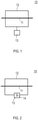
- Fig. 1
- shows a schematic illustration of a shaft bearing assembly according to embodiments described herein including a pressure reduction device;
- Fig. 2
- shows a schematic illustration of a shaft bearing assembly according to further embodiments described herein, wherein the pressure reduction device is at least partially integrated in the bearing housing;
- Fig. 3
- shows a schematic illustration of a shaft bearing assembly according to further embodiments described herein, wherein the pressure reduction device is provided inside the bearing housing;
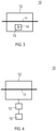
- Fig. 4
- shows a schematic illustration of a shaft bearing assembly according to further embodiments described herein having a pressure reduction device and at least one further pressure reduction device connected in series;
- Fig. 5
- shows a schematic illustration of a shaft bearing assembly according to further embodiments described herein having a pressure reduction device and at least one further pressure reduction device connected in parallel;
- Fig. 6
- shows a schematic illustration of a shaft bearing assembly according to further embodiments described herein having a pressure controller for controlling the underpressure generated by the pressure reduction device;
- Fig. 7
- shows a schematic illustration of an in internal combustion engine including a shaft bearing assembly according to any embodiments described herein; and
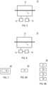
- Figs. 8A and 8B
- show block diagrams for illustrating embodiments of a method of reducing a pressure inside a bearing housing as described herein.
- Reference will now be made in detail to the various embodiments, one or more examples of which are illustrated in each figure. Each example is provided by way of explanation and is not meant as a limitation. For example, features illustrated or described as part of one embodiment can be used on or in conjunction with any other embodiment to yield yet a further embodiment. It is intended that the present disclosure includes such modifications and variations.
- Within the following description of the drawings, the same reference numbers refer to the same or to similar components. Generally, only the differences with respect to the individual embodiments are described. Unless specified otherwise, the description of a part or aspect in one embodiment can apply to a corresponding part or aspect in another embodiment as well.
- With exemplary reference to
Fig. 1 , ashaft bearing assembly 10 according to the present disclosure is described. According to embodiments which can be combined with any other embodiments described herein, theshaft bearing assembly 10 has ashaft 11 supported in a bearinghousing 12. Further, theshaft bearing assembly 10 includes apressure reduction device 13 for generating an underpressure inside the bearinghousing 12. In this regard, it is to be noted that the expression "underpressure inside the bearing housing" is to be understood in that the pressure inside the bearing housing is lower than outside of the bearing housing. Typically, the outside of the bearing housing is at atmospheric pressure. Accordingly, an "underpressure" may be understood as a pressure below atmospheric pressure. Thepressure reduction device 13 is operated by employing an incompressible fluid. In particular, the incompressible fluid can be oil. In this regard, it is to be noted that apressure reduction device 13 being operated by employing an incompressible fluid is to be understood in that the incompressible fluid is used as working fluid for operating the pressure reduction device, particularly for providing energy for operating the pressure reduction device. - Accordingly, beneficially a shaft bearing assembly with an improved sealing performance is provided. In particular, the implementation of a bearing assembly with a pressure reduction device as described herein beneficially provides for avoiding the occurrence of a positive pressure gradient across bearing housing interfaces, e.g. shaft seals.
- According to embodiments which can be combined with any other embodiments described herein, the
pressure reduction device 13 is based on the principle of a jet pump. In other words, the pressure reduction device can be understood as a device working on the principle of a jet pump. Thepressure reduction device 13 is configured to produce and maintain an underpressure inside the bearinghousing 12. In particular, the generation of underpressure inside the bearinghousing 12 by thepressure reduction device 13 is based on the effect that a jet stream is injected with high kinetic energy (so called driving flow), which in turn allows a momentum exchange with a suction fluid, e.g. oil, for providing a suction flow. In particular, typically the suction fluid consists out of oil (e.g. from bearings and, for example, cooling holes) and working fluid, particularly air or exhaust gas, of the turbocharger or turbocompound, respectively. Thereby, the suction fluid gets accelerated and the desired underpressure can be generated. In this regard, it is to be noted that typically the oil supply of an internal combustion engine is under pressure of several bars, which provides a sufficient energy reservoir since for the suction effect only a few millibars are needed. Accordingly, beneficially there is no need for the pressure reduction device to operate at a high efficiency level, since the energy reservoir provided by the oil supply is significantly larger than the energy needed for operating the pressure reduction device. In other words, for the case of the pressure reduction device being based on the working principle of a jet pump, it may be less relevant whether all basic elements of a jet pump like for example suction chamber, mixing throat or diffuser are finally considered or whether they are designed within well-known design criteria. In this regard, it is to be noted that there are various installation possibilities for the pressure reduction device. - According to embodiments which can be combined with any other embodiments described herein, the
pressure reduction device 13 is configured to be operated by a driving oil flow and a suction oil flow. The driving oil flow is provided by oil provided from an oil supply for providing oil to the bearings of the shaft bearing assembly. The suction oil flow is provided by oil that flows out of the bearings. More specifically, the suction oil flow may be provided by oil that out of the bearings and cooling holes. In particular, depending on the field of application (e.g. medium speed applications), cooling holes or cooling bores may be provided in the bearing casing on the turbine side. The cooling holes are fed by oil of the turbocharger, to cool down the temperature level of the turbine sided walls, e.g. by spray cooling. In other words, like bearings, e.g. radial or axial bearings, the cooling holes act like an additional "oil consumer" and thus, in the case they are implemented, contribute to the suction flow of the pressure reduction device, e.g. a jet pump. - With exemplary reference to
Fig. 2 , according to embodiments which can be combined with any other embodiments described herein, thepressure reduction device 13 includes at least onenozzle 14. During operation of thepressure reduction device 13, oil provided from an external oil supply is provided through the at least onenozzle 14. In particular, the oil may be understood as working fluid for the pressure reduction device and the at least onenozzle 14 is used for generating a jet stream. Typically, the nozzle is fed by oil of an oil supply. For example, the oil supply can be the oil supply for the bearings of the shaft bearing assembly. More generally, the oil supply can be an oil supply of a turbo compound and/or a charging system, for instance of an internal combustion engine. The oily supply may be an internal oil supply or an external oil supply. - According to embodiments which can be combined with any other embodiments described herein, the at least one
nozzle 14 is selected from the group consisting of: a single jet nozzle, a multiple jet nozzle (e.g. a double jet nozzle), a annular ring nozzle, a nozzle configured for injecting a jet stream as swirl flow, and a lobed nozzle. - According to embodiments which can be combined with any other embodiments described herein, the
pressure reduction device 13 is connected with the bearinghousing 12. In particular, thepressure reduction device 13 may include a suction chamber which may be connected via a tube fitting with the bearing housing. - With exemplary reference to
Fig. 3 , according to embodiments which can be combined with any other embodiments described herein, thepressure reduction device 13 is at least partially integrated in the bearinghousing 12. In other words, thepressure reduction device 13 can be fully or partly integrated in the bearinghousing 12. Accordingly, beneficially a more space saving design can be provided. Alternatively, as schematically illustrated inFig. 4 , thepressure reduction device 13 can be provided inside the bearinghousing 12. Accordingly, thepressure reduction device 13 may be arranged and configured for generating a local lower pressure inside the bearinghousing 12. - According to embodiments which can be combined with any other embodiments described herein, the
shaft bearing assembly 10 may further include one or more furtherpressure reduction devices 15, as schematically shown inFig. 4 . For example, the one or more furtherpressure reduction devices 15 can be connected in series with thepressure reduction device 13, as show inFig. 4 . Additionally or alternatively, the one or more furtherpressure reduction devices 15 can be connected in parallel with thepressure reduction device 13, as exemplarily shown inFig. 5 . - With exemplary reference to
Fig. 6 , according to embodiments which can be combined with any other embodiments described herein, theshaft bearing assembly 10 includes acontroller 16 for controlling the underpressure generated by thepressure reduction device 13 and/or the one or more furtherpressure reduction devices 15. The controller may be an actively driven controller or a passively driven controller. For instance, the controller can be configured for setting up the suction pressure of the pressure reduction device. Further, the controller may be configured for switching the pressure reduction device on or off. - Hence, in view of the embodiments of the shaft bearing assembly as described herein, it is to be understood that by employing the shaft bearing assembly as described herein in a turbo compound and/or in a charging system an improved turbo compound and/or a charging system can be provided. Accordingly, an improved internal combustion engine can be provided by providing a turbo compound and/or a charging system having a shaft bearing assembly according to any embodiments described herein.
Fig. 7 schematically shows aninternal combustion engine 20 including ashaft bearing assembly 10 according to any embodiments described herein. - With exemplary reference to the block diagrams shown in
Figs. 8A and 8B , embodiments of amethod 30 of reducing a pressure inside a bearinghousing 12 supporting ashaft 11 according to the present disclosure are described. According to embodiments which can be combined with any other embodiments described herein, themethod 30 includes using (represented byblock 31 inFig. 8A ) an incompressible fluid for operating apressure reduction device 13 for generating an underpressure inside the bearinghousing 12. - According to embodiments of the
method 30 which can be combined with any other embodiments described herein, using (represented byblock 31 inFig. 8A ) the incompressible fluid for operating thepressure reduction device 13 includes providing (represented byblock 32 inFig. 8B ) a driving oil flow and a suction oil flow for operating thepressure reduction device 13. The driving oil flow is provided by oil from an oil supply for the bearings. The suction oil flow is provided by oil flowing out of the bearings. - According to embodiments which can be combined with any other embodiments described herein, the
method 30 further includes using (represented byblock 33 inFig. 8B ) the incompressible fluid for operating one or more furtherpressure reduction devices 15. As exemplarily described with reference toFigs. 4 and5 , the one or more furtherpressure reduction devices 15 can be connected in parallel and/or in series with thepressure reduction device 13. - According to embodiments which can be combined with any other embodiments described herein, the
method 30 further includes controlling (represented byblock 34 inFig. 8B ) the underpressure generated by thepressure reduction device 13 by using acontroller 16. Additionally, the method may include controlling the underpressure generated by the one or more furtherpressure reduction devices 15. In particular, controlling of thepressure reduction device 13 and/or of the one or more furtherpressure reduction devices 15 can be done by using a mechanical working valve (e.g. a spring valve) for controlling, for example, the difference pressure across the sealing. Accordingly, the occurrence of the above mentioned positive pressure gradient can be avoided. Further, the pressure build-up of thepressure reduction device 13 and/or of the one or more furtherpressure reduction devices 15 could directly be controlled by using a mechanical valve. It is to be noted that instead of a mechanical working controller, an electrical device could be employed. Further, it is to be understood that there are several possibilities for controlling thepressure reduction device 13 and/or the one or more furtherpressure reduction devices 15. For example, depending on the turbocharger operating point, a purely hydraulic control via the differential pressure of the bearing point may be used. - Further, a purely electrically controlled valve, e.g. in the driving flow supply of the
pressure reduction device 13 and/or the one or more furtherpressure reduction devices 15, can be used to control thepressure reduction device 13 and/or the one or more furtherpressure reduction devices 15. In this case, the driving flow is controlled via the turbocharger speed or the operating point of the turbocharger, which has the advantage that switching off thepressure reduction device 13 and/or the one or more furtherpressure reduction devices 15 is easy to realize for uncritical turbocharger operating points. - In view of the embodiments described herein, it is to be understood that beneficially a shaft bearing assembly as well as a method is provided with which, compared to the state of the art, an improved sealing performance can be obtained. In particular, embodiments as described herein beneficially avoid occurrence of positive pressure gradients across bearing housing interfaces, particularly across shaft seals.
- While the foregoing is directed to embodiments, other and further embodiments may be devised without departing from the basic scope, and the scope is determined by the claims that follow.
-
- 10 shaft bearing assembly
- 11 shaft
- 12 bearing housing
- 13 pressure reduction device
- 14 nozzle
- 15 one or more further pressure reduction devices
- 16 pressure controller
- 20 internal combustion engine
- 30 method of reducing a pressure inside a bearing housing
- 31-34 bocks of block diagram for illustrating the method of reducing a pressure inside a bearing housing
Claims (15)
- A shaft bearing assembly (10) having a shaft (11) supported in a bearing housing (12), comprising a pressure reduction device (13) for generating an underpressure inside the bearing housing (12), the pressure reduction device (13) being operated by employing an incompressible fluid.
- The shaft bearing assembly (10) of claim 1, wherein the incompressible fluid is oil.
- The shaft bearing assembly (10) of claim 1 or 2, wherein the pressure reduction device (13) is based on the principle of a jet pump.
- The shaft bearing assembly (10) of any of claims 1 to 3, wherein the pressure reduction device (13) is configured to be operated by a driving oil flow and a suction oil flow, wherein the driving oil flow is provided by oil provided from an oil supply for the bearings of the shaft bearing assembly (10), and wherein the suction oil flow is provided by oil flowing out of the bearings.
- The shaft bearing assembly (10) of any of claims 1 to 4, wherein the pressure reduction device (13) comprises at least one nozzle (14), and wherein oil of an external oil supply is provided through the at least one nozzle (14) during operation of the pressure reduction device (13).
- The shaft bearing assembly (10) of claim 5, wherein the at least one nozzle (14) is selected from the group consisting of: a single jet nozzle, a multiple jet nozzle, a annular ring nozzle, a nozzle configured for injecting a jet stream as swirl flow, and a lobed nozzle.
- The shaft bearing assembly (10) of any of claims 1 to 6, wherein the pressure reduction device (13) is connected with the bearing housing (12).
- The shaft bearing assembly (10) of any of claims 1 to 7, wherein the pressure reduction device (13) is at least partially integrated in the bearing housing (12), or wherein the pressure reduction device (13) is provided inside the bearing housing (12).
- The shaft bearing assembly (10) of any of claims 1 to 8, further comprising one or more further pressure reduction devices (15), the one or more further pressure reduction devices (15) being connected in parallel and/ or in series with the pressure reduction device (13).
- The shaft bearing assembly (10) of any of claims 1 to 9, further comprising a controller (16) for controlling the underpressure generated by the pressure reduction device (13).
- An internal combustion engine (20) comprising a turbo compound and/or a charging system having a shaft bearing assembly (10) according to any of claims 1 to 10.
- A method (30) of reducing a pressure inside a bearing housing (12) supporting a shaft (11), the method comprising using (31) an incompressible fluid for operating a pressure reduction device (13) for generating an underpressure inside the bearing housing (12).
- The method (30) of claim 12, wherein using (31) the incompressible fluid for operating the pressure reduction device (13) comprises providing (32) a driving oil flow and a suction oil flow for operating the pressure reduction device (13), the driving oil flow being provided by oil from an oil supply for the bearings, and the suction oil flow being provided by oil flowing out of the bearings.
- The method (30) of claim 12 or 13, further comprising using (33) the incompressible fluid for operating one or more further pressure reduction devices (15), the one or more further pressure reduction devices (15) being connected in parallel and/or in series with the pressure reduction device (13).
- The method (30) of any of claims 12 to 14, further comprising controlling (34) the underpressure generated by the pressure reduction device (13) by using a controller (16).
Priority Applications (7)
| Application Number | Priority Date | Filing Date | Title |
|---|---|---|---|
| EP20189222.1A EP3951139A1 (en) | 2020-08-03 | 2020-08-03 | Shaft bearing assembly having a pressure reduction device and method of reducing a pressure inside a bearing housing supporting a shaft |
| US18/018,922 US11953056B2 (en) | 2020-08-03 | 2021-06-28 | Shaft bearing assembly having a pressure reduction device and method of reducing a pressure inside a bearing housing supporting a shaft |
| PCT/EP2021/067709 WO2022028776A1 (en) | 2020-08-03 | 2021-06-28 | Shaft bearing assembly having a pressure reduction device and method of reducing a pressure inside a bearing housing supporting a shaft |
| JP2023505959A JP7617243B2 (en) | 2020-08-03 | 2021-06-28 | Shaft support assembly having a pressure reducing device and method for reducing pressure within a bearing housing supporting a shaft - Patents.com |
| KR1020237007260A KR102903769B1 (en) | 2020-08-03 | 2021-06-28 | Shaft bearing assembly having a pressure reducing device, and method for reducing pressure within a bearing housing supporting a shaft |
| EP21736607.9A EP4189220B1 (en) | 2020-08-03 | 2021-06-28 | Shaft bearing assembly having a pressure reduction device and method of reducing a pressure inside a bearing housing supporting a shaft |
| CN202180058528.2A CN116324128A (en) | 2020-08-03 | 2021-06-28 | Shaft bearing assembly with pressure relief device and method of reducing internal pressure of a bearing housing supporting a shaft |
Applications Claiming Priority (1)
| Application Number | Priority Date | Filing Date | Title |
|---|---|---|---|
| EP20189222.1A EP3951139A1 (en) | 2020-08-03 | 2020-08-03 | Shaft bearing assembly having a pressure reduction device and method of reducing a pressure inside a bearing housing supporting a shaft |
Publications (1)
| Publication Number | Publication Date |
|---|---|
| EP3951139A1 true EP3951139A1 (en) | 2022-02-09 |
Family
ID=71944003
Family Applications (2)
| Application Number | Title | Priority Date | Filing Date |
|---|---|---|---|
| EP20189222.1A Withdrawn EP3951139A1 (en) | 2020-08-03 | 2020-08-03 | Shaft bearing assembly having a pressure reduction device and method of reducing a pressure inside a bearing housing supporting a shaft |
| EP21736607.9A Active EP4189220B1 (en) | 2020-08-03 | 2021-06-28 | Shaft bearing assembly having a pressure reduction device and method of reducing a pressure inside a bearing housing supporting a shaft |
Family Applications After (1)
| Application Number | Title | Priority Date | Filing Date |
|---|---|---|---|
| EP21736607.9A Active EP4189220B1 (en) | 2020-08-03 | 2021-06-28 | Shaft bearing assembly having a pressure reduction device and method of reducing a pressure inside a bearing housing supporting a shaft |
Country Status (6)
| Country | Link |
|---|---|
| US (1) | US11953056B2 (en) |
| EP (2) | EP3951139A1 (en) |
| JP (1) | JP7617243B2 (en) |
| KR (1) | KR102903769B1 (en) |
| CN (1) | CN116324128A (en) |
| WO (1) | WO2022028776A1 (en) |
Citations (3)
| Publication number | Priority date | Publication date | Assignee | Title |
|---|---|---|---|---|
| EP0626503A1 (en) * | 1993-05-25 | 1994-11-30 | Societe Nationale D'etude Et De Construction De Moteurs D'aviation "Snecma" | Depressurization device for bearing lubrication chambers |
| EP2154348A2 (en) * | 2008-08-13 | 2010-02-17 | Cummins Turbo Technologies Limited | Engine braking method and system |
| EP2781704A1 (en) * | 2013-03-01 | 2014-09-24 | Rolls-Royce plc | Chamber fluid removal system |
Family Cites Families (9)
| Publication number | Priority date | Publication date | Assignee | Title |
|---|---|---|---|---|
| GB942842A (en) * | 1961-05-10 | 1963-11-27 | Rolls Royce | Gas turbine engine |
| JPS6235195U (en) * | 1985-08-22 | 1987-03-02 | ||
| JP2000192971A (en) * | 1998-12-28 | 2000-07-11 | Nsk Ltd | Rolling bearing lubrication device |
| JP2000266066A (en) * | 1999-03-18 | 2000-09-26 | Koyo Seiko Co Ltd | Bearing lubrication and bearing lubricating device |
| FR2961856B1 (en) * | 2010-06-25 | 2014-05-16 | Snecma | JET TROUBLE FOR BEARING ENCLOSURE OF TURBOMACHINE SUPPLIED BY LUBRICATING OIL |
| JP5429085B2 (en) | 2010-07-12 | 2014-02-26 | トヨタ自動車株式会社 | Turbocharger |
| WO2014060656A1 (en) * | 2012-10-19 | 2014-04-24 | Snecma | Jet pump for depressurizing lubrication chambers of a turbomachine, having independent double injectors |
| DE102013110726A1 (en) * | 2013-09-27 | 2015-04-02 | Abb Turbo Systems Ag | Bearing housing ventilation system for a turbocharger assembly |
| US10927845B2 (en) * | 2017-05-24 | 2021-02-23 | The Boeing Company | Seal assembly and method for reducing aircraft engine oil leakage |
-
2020
- 2020-08-03 EP EP20189222.1A patent/EP3951139A1/en not_active Withdrawn
-
2021
- 2021-06-28 JP JP2023505959A patent/JP7617243B2/en active Active
- 2021-06-28 EP EP21736607.9A patent/EP4189220B1/en active Active
- 2021-06-28 CN CN202180058528.2A patent/CN116324128A/en active Pending
- 2021-06-28 US US18/018,922 patent/US11953056B2/en active Active
- 2021-06-28 WO PCT/EP2021/067709 patent/WO2022028776A1/en not_active Ceased
- 2021-06-28 KR KR1020237007260A patent/KR102903769B1/en active Active
Patent Citations (3)
| Publication number | Priority date | Publication date | Assignee | Title |
|---|---|---|---|---|
| EP0626503A1 (en) * | 1993-05-25 | 1994-11-30 | Societe Nationale D'etude Et De Construction De Moteurs D'aviation "Snecma" | Depressurization device for bearing lubrication chambers |
| EP2154348A2 (en) * | 2008-08-13 | 2010-02-17 | Cummins Turbo Technologies Limited | Engine braking method and system |
| EP2781704A1 (en) * | 2013-03-01 | 2014-09-24 | Rolls-Royce plc | Chamber fluid removal system |
Also Published As
| Publication number | Publication date |
|---|---|
| CN116324128A (en) | 2023-06-23 |
| EP4189220B1 (en) | 2024-07-17 |
| WO2022028776A1 (en) | 2022-02-10 |
| JP7617243B2 (en) | 2025-01-17 |
| KR20230044503A (en) | 2023-04-04 |
| US20230296133A1 (en) | 2023-09-21 |
| EP4189220A1 (en) | 2023-06-07 |
| KR102903769B1 (en) | 2025-12-24 |
| JP2023537288A (en) | 2023-08-31 |
| US11953056B2 (en) | 2024-04-09 |
Similar Documents
| Publication | Publication Date | Title |
|---|---|---|
| EP1512844B1 (en) | Gas turbine installation and cooling air supplying method | |
| US6003298A (en) | Steam driven variable speed booster compressor for gas turbine | |
| US8616832B2 (en) | Turbine assemblies with impingement cooling | |
| US6910852B2 (en) | Methods and apparatus for cooling gas turbine engine rotor assemblies | |
| JP2015025428A (en) | Axial flow compressor, gas turbine equipped with axial flow compressor, and method for remodeling axial flow compressor | |
| US11873729B2 (en) | Turbofan engine comprising a device for regulating the flow rate of cooling fluid | |
| GB2437969A (en) | Fluid flow control system | |
| US11920490B2 (en) | Charging device with thrust bearing | |
| EP0076668B1 (en) | Turbo-machines with bleed-off means | |
| US20190010869A1 (en) | Systems and methods for cooling components of a gas turbine | |
| US11953056B2 (en) | Shaft bearing assembly having a pressure reduction device and method of reducing a pressure inside a bearing housing supporting a shaft | |
| CN218206862U (en) | Gas turbine | |
| CN112664273B (en) | Organic working medium expander rotor | |
| JP2011208504A (en) | Structure for supplying cooling air of twin-screw gas turbine | |
| US20140017099A1 (en) | Turbocharger system with reduced thrust load | |
| EP3693561A1 (en) | Shaft seal system, turbomachine with shaft seal system, and method of sealing a shaft | |
| US20250180032A1 (en) | Centrifugal compressor with energy recovery from a recycle line | |
| US20250043726A1 (en) | Containment ring cavity pressurization system | |
| WO2023135174A1 (en) | Sealing device, turbomachine and method of sealing a bearing cover from a bearing housing | |
| RU2482311C1 (en) | Gas turbine engine with aft location of open propeller fan | |
| JP2022067464A (en) | Compression device and gas turbine system |
Legal Events
| Date | Code | Title | Description |
|---|---|---|---|
| PUAI | Public reference made under article 153(3) epc to a published international application that has entered the european phase |
Free format text: ORIGINAL CODE: 0009012 |
|
| STAA | Information on the status of an ep patent application or granted ep patent |
Free format text: STATUS: THE APPLICATION HAS BEEN PUBLISHED |
|
| AK | Designated contracting states |
Kind code of ref document: A1 Designated state(s): AL AT BE BG CH CY CZ DE DK EE ES FI FR GB GR HR HU IE IS IT LI LT LU LV MC MK MT NL NO PL PT RO RS SE SI SK SM TR |
|
| STAA | Information on the status of an ep patent application or granted ep patent |
Free format text: STATUS: THE APPLICATION IS DEEMED TO BE WITHDRAWN |
|
| 18D | Application deemed to be withdrawn |
Effective date: 20220810 |