EP3950472A1 - Protection structure of rear combination lamp - Google Patents
Protection structure of rear combination lamp Download PDFInfo
- Publication number
- EP3950472A1 EP3950472A1 EP21189237.7A EP21189237A EP3950472A1 EP 3950472 A1 EP3950472 A1 EP 3950472A1 EP 21189237 A EP21189237 A EP 21189237A EP 3950472 A1 EP3950472 A1 EP 3950472A1
- Authority
- EP
- European Patent Office
- Prior art keywords
- combination lamp
- undercover
- rear combination
- lamp
- vehicle
- Prior art date
- Legal status (The legal status is an assumption and is not a legal conclusion. Google has not performed a legal analysis and makes no representation as to the accuracy of the status listed.)
- Pending
Links
Images



Classifications
-
- F—MECHANICAL ENGINEERING; LIGHTING; HEATING; WEAPONS; BLASTING
- F21—LIGHTING
- F21S—NON-PORTABLE LIGHTING DEVICES; SYSTEMS THEREOF; VEHICLE LIGHTING DEVICES SPECIALLY ADAPTED FOR VEHICLE EXTERIORS
- F21S43/00—Signalling devices specially adapted for vehicle exteriors, e.g. brake lamps, direction indicator lights or reversing lights
- F21S43/50—Signalling devices specially adapted for vehicle exteriors, e.g. brake lamps, direction indicator lights or reversing lights characterised by aesthetic components not otherwise provided for, e.g. decorative trim, partition walls or covers
-
- B—PERFORMING OPERATIONS; TRANSPORTING
- B62—LAND VEHICLES FOR TRAVELLING OTHERWISE THAN ON RAILS
- B62J—CYCLE SADDLES OR SEATS; AUXILIARY DEVICES OR ACCESSORIES SPECIALLY ADAPTED TO CYCLES AND NOT OTHERWISE PROVIDED FOR, e.g. ARTICLE CARRIERS OR CYCLE PROTECTORS
- B62J6/00—Arrangement of optical signalling or lighting devices on cycles; Mounting or supporting thereof; Circuits therefor
- B62J6/04—Rear lights
-
- B—PERFORMING OPERATIONS; TRANSPORTING
- B60—VEHICLES IN GENERAL
- B60Q—ARRANGEMENT OF SIGNALLING OR LIGHTING DEVICES, THE MOUNTING OR SUPPORTING THEREOF OR CIRCUITS THEREFOR, FOR VEHICLES IN GENERAL
- B60Q1/00—Arrangement of optical signalling or lighting devices, the mounting or supporting thereof or circuits therefor
- B60Q1/26—Arrangement of optical signalling or lighting devices, the mounting or supporting thereof or circuits therefor the devices being primarily intended to indicate the vehicle, or parts thereof, or to give signals, to other traffic
- B60Q1/2607—Arrangement of optical signalling or lighting devices, the mounting or supporting thereof or circuits therefor the devices being primarily intended to indicate the vehicle, or parts thereof, or to give signals, to other traffic comprising at least two indicating lamps
-
- B—PERFORMING OPERATIONS; TRANSPORTING
- B60—VEHICLES IN GENERAL
- B60Q—ARRANGEMENT OF SIGNALLING OR LIGHTING DEVICES, THE MOUNTING OR SUPPORTING THEREOF OR CIRCUITS THEREFOR, FOR VEHICLES IN GENERAL
- B60Q1/00—Arrangement of optical signalling or lighting devices, the mounting or supporting thereof or circuits therefor
- B60Q1/26—Arrangement of optical signalling or lighting devices, the mounting or supporting thereof or circuits therefor the devices being primarily intended to indicate the vehicle, or parts thereof, or to give signals, to other traffic
- B60Q1/2696—Mounting of devices using LEDs
-
- B—PERFORMING OPERATIONS; TRANSPORTING
- B62—LAND VEHICLES FOR TRAVELLING OTHERWISE THAN ON RAILS
- B62J—CYCLE SADDLES OR SEATS; AUXILIARY DEVICES OR ACCESSORIES SPECIALLY ADAPTED TO CYCLES AND NOT OTHERWISE PROVIDED FOR, e.g. ARTICLE CARRIERS OR CYCLE PROTECTORS
- B62J15/00—Mud-guards for wheels
-
- B—PERFORMING OPERATIONS; TRANSPORTING
- B62—LAND VEHICLES FOR TRAVELLING OTHERWISE THAN ON RAILS
- B62J—CYCLE SADDLES OR SEATS; AUXILIARY DEVICES OR ACCESSORIES SPECIALLY ADAPTED TO CYCLES AND NOT OTHERWISE PROVIDED FOR, e.g. ARTICLE CARRIERS OR CYCLE PROTECTORS
- B62J17/00—Weather guards for riders; Fairings or stream-lining parts not otherwise provided for
-
- B—PERFORMING OPERATIONS; TRANSPORTING
- B62—LAND VEHICLES FOR TRAVELLING OTHERWISE THAN ON RAILS
- B62J—CYCLE SADDLES OR SEATS; AUXILIARY DEVICES OR ACCESSORIES SPECIALLY ADAPTED TO CYCLES AND NOT OTHERWISE PROVIDED FOR, e.g. ARTICLE CARRIERS OR CYCLE PROTECTORS
- B62J6/00—Arrangement of optical signalling or lighting devices on cycles; Mounting or supporting thereof; Circuits therefor
- B62J6/04—Rear lights
- B62J6/045—Rear lights indicating braking
-
- F—MECHANICAL ENGINEERING; LIGHTING; HEATING; WEAPONS; BLASTING
- F21—LIGHTING
- F21S—NON-PORTABLE LIGHTING DEVICES; SYSTEMS THEREOF; VEHICLE LIGHTING DEVICES SPECIALLY ADAPTED FOR VEHICLE EXTERIORS
- F21S43/00—Signalling devices specially adapted for vehicle exteriors, e.g. brake lamps, direction indicator lights or reversing lights
- F21S43/10—Signalling devices specially adapted for vehicle exteriors, e.g. brake lamps, direction indicator lights or reversing lights characterised by the light source
- F21S43/13—Signalling devices specially adapted for vehicle exteriors, e.g. brake lamps, direction indicator lights or reversing lights characterised by the light source characterised by the type of light source
- F21S43/14—Light emitting diodes [LED]
-
- F—MECHANICAL ENGINEERING; LIGHTING; HEATING; WEAPONS; BLASTING
- F21—LIGHTING
- F21S—NON-PORTABLE LIGHTING DEVICES; SYSTEMS THEREOF; VEHICLE LIGHTING DEVICES SPECIALLY ADAPTED FOR VEHICLE EXTERIORS
- F21S43/00—Signalling devices specially adapted for vehicle exteriors, e.g. brake lamps, direction indicator lights or reversing lights
- F21S43/10—Signalling devices specially adapted for vehicle exteriors, e.g. brake lamps, direction indicator lights or reversing lights characterised by the light source
- F21S43/19—Attachment of light sources or lamp holders
- F21S43/195—Details of lamp holders, terminals or connectors
-
- B—PERFORMING OPERATIONS; TRANSPORTING
- B60—VEHICLES IN GENERAL
- B60Q—ARRANGEMENT OF SIGNALLING OR LIGHTING DEVICES, THE MOUNTING OR SUPPORTING THEREOF OR CIRCUITS THEREFOR, FOR VEHICLES IN GENERAL
- B60Q1/00—Arrangement of optical signalling or lighting devices, the mounting or supporting thereof or circuits therefor
- B60Q1/0005—Devices preventing the lights from becoming dirty or damaged, e.g. protection grids or cleaning by air flow
-
- B—PERFORMING OPERATIONS; TRANSPORTING
- B62—LAND VEHICLES FOR TRAVELLING OTHERWISE THAN ON RAILS
- B62K—CYCLES; CYCLE FRAMES; CYCLE STEERING DEVICES; RIDER-OPERATED TERMINAL CONTROLS SPECIALLY ADAPTED FOR CYCLES; CYCLE AXLE SUSPENSIONS; CYCLE SIDECARS, FORECARS, OR THE LIKE
- B62K11/00—Motorcycles, engine-assisted cycles or motor scooters with one or two wheels
-
- F—MECHANICAL ENGINEERING; LIGHTING; HEATING; WEAPONS; BLASTING
- F21—LIGHTING
- F21W—INDEXING SCHEME ASSOCIATED WITH SUBCLASSES F21K, F21L, F21S and F21V, RELATING TO USES OR APPLICATIONS OF LIGHTING DEVICES OR SYSTEMS
- F21W2103/00—Exterior vehicle lighting devices for signalling purposes
-
- F—MECHANICAL ENGINEERING; LIGHTING; HEATING; WEAPONS; BLASTING
- F21—LIGHTING
- F21W—INDEXING SCHEME ASSOCIATED WITH SUBCLASSES F21K, F21L, F21S and F21V, RELATING TO USES OR APPLICATIONS OF LIGHTING DEVICES OR SYSTEMS
- F21W2107/00—Use or application of lighting devices on or in particular types of vehicles
- F21W2107/10—Use or application of lighting devices on or in particular types of vehicles for land vehicles
- F21W2107/13—Use or application of lighting devices on or in particular types of vehicles for land vehicles for cycles
- F21W2107/17—Use or application of lighting devices on or in particular types of vehicles for land vehicles for cycles for motorcycles
Definitions
- the present invention relates to a protection structure of a rear combination lamp.
- a rear combination lamp including a plurality of assembled lamps is generally provided at a rear portion of a straddle-type vehicle such as a motorcycle.
- a rear fender is installed below a rear combination lamp to protect the rear combination lamp from mud or the like splashed by a rear wheel (for example, see Patent Literature 1).
- the rear fender described in Patent Literature 1 extends rearward from a lower edge of the rear combination lamp and covers an upper side of the rear wheel. With the rear fender, mud or the like is prevented from adhering to the rear combination lamp and visibility of the lamp is ensured.
- Patent Literature 1 Japanese Patent No. 4104344
- the rear combination lamp Since the rear combination lamp includes a plurality of integrated lamps, the rear combination lamp has a large size in the vehicle width direction. In order to protect the entire rear combination lamp by the rear fender, it is necessary to increase the size of the rear fender, and the degree of freedom of the shape of the rear fender is also reduced. An increase in the size of the rear fender also deteriorates the appearance of a vehicle.
- the present invention has been made in view of the above circumstance, and an object of the present invention is to provide a protection structure of a rear combination lamp that can improve the protection performance of the rear combination lamp while preventing a decrease in the appearance of a vehicle.
- a protection structure of a rear combination lamp provided at a rear portion of a straddle-type vehicle.
- the protection structure of the rear combination lamp includes an undercover covering a rear combination lamp from below, and a rear fender covering a rear wheel from above, the rear fender being below the undercover.
- the undercover extends along a lower edge of the rear combination lamp. A size of the rear fender in a vehicle width direction is smaller than a size of the undercover in the vehicle width direction in a vehicle rear view.
- the rear combination lamp is covered from below by the undercover along the lower edge of the rear combination lamp. Even when the size of the rear fender in the vehicle width direction is smaller than the size of the undercover in the vehicle width direction, the rear combination lamp is protected from mud or the like splashed by the rear wheel. By protecting the rear combination lamp with the undercover and reducing the size of the rear fender, it is possible to improve the protection performance of the rear combination lamp while preventing deterioration of the appearance of the vehicle.
- a rear combination lamp provided at a rear portion of a straddle-type vehicle is covered from below by an undercover along a lower edge of the rear combination lamp.
- a rear wheel is covered with a rear fender from above. Even when the size of the rear fender in the vehicle width direction is smaller than the size of the undercover in the vehicle width direction, the rear combination lamp is protected from mud or the like splashed by the rear wheel.
- FIG. 1 is a left view of a straddle-type vehicle according to the present embodiment.
- an arrow FR indicates a vehicle front side
- an arrow RE indicates a vehicle rear side
- an arrow L indicates a vehicle left side
- an arrow R indicates a vehicle right side.
- a straddle-type vehicle 1 includes various components such as an engine 16 and an electrical system that are mounted on a twin spar-type vehicle body frame 10 formed by aluminum casting.
- the vehicle body frame 10 includes a pair of main frames 11 branching from a head pipe (not shown) to the left and right and extending rearward, and a pair of down frames (not shown) branching from the head pipe to the left and right and extending downward.
- a rear portion of the engine 16 is supported by the pair of main frames 11, and a front portion of the engine 16 is supported by the pair of down frames.
- Front portions of the pair of main frames 11 serve as tank rails 12 located above the engine 16, and a fuel tank 17 is supported by the tank rails 12.
- Rear portions of the pair of main frames 11 serve as body frames 13 located in rear of the engine 16, and swing arms 18 are swingably supported in substantially middle positions of the body frames 13 in the upper-lower direction.
- Seat rails 14 (see FIG. 5 ) and a back stay extend rearward from upper portions of the body frames 13.
- a rider seat 21 and a pillion seat 22 are supported on the seat rails 14 in rear of the fuel tank 17.
- a pair of front forks 23 are steerably supported on the head pipe via a steering shaft (not shown).
- a front wheel 25 is rotatably supported by lower portions of the front forks 23, and an upper portion of the front wheel 25 is covered with a front fender 26.
- the swing arms 18 extend rearward from the body frames 13.
- a rear wheel 28 is rotatably supported at rear ends of the swing arms 18, and an upper side of the rear wheel 28 is covered with a rear fender 29.
- the engine 16 is coupled to the rear wheel 28 via a chain drive-type speed reduction mechanism, and power from the engine 16 is transmitted to the rear wheel 28 via the speed reduction mechanism.
- the straddle-type vehicle 1 is covered with various covers serving as a vehicle body exterior.
- a vehicle rear portion is covered with a frame cover 30, and a rear combination lamp 40 is provided on a rear side of the frame cover 30.
- the rear combination lamp 40 is located above the rear wheel 28, and mud or the like is splashed from the rear wheel 28 toward the rear combination lamp 40.
- the upper side of the rear wheel 28 is covered with the rear fender 29, it is difficult for the rear fender 29 to prevent mud or the like from adhering to the rear combination lamp 40 having a large size in the vehicle width direction.
- the rear fender 29 tends to be reduced in size from the viewpoint of improving the appearance of a vehicle in recent years.
- an undercover 60 is attached along a lower edge of the rear combination lamp 40 so that the rear combination lamp 40 can be protected from mud or the like splashed to the rear wheel 28 even when the small rear fender 29 is used.
- the rear combination lamp 40 is covered by the undercover 60 from below, and mud or the like is prevented from adhering to the rear combination lamp 40.
- FIG. 2 is a perspective view of the vehicle rear portion according to the present embodiment.
- FIG. 3 is a rear view of the vehicle rear portion according to the present embodiment.
- FIG. 4 is a side view of the vehicle rear portion according to the present embodiment.
- FIG. 5 is a perspective view according to the present embodiment in which an upper side of the vehicle rear portion is opened.
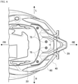
- FIG. 6 is a bottom view of the vehicle rear portion according to the present embodiment.
- the frame cover 30 includes a pair of side covers 31 covering side portions of the seat rails 14, a center cover 32 connecting the pair of side covers 31 in rear of the pillion seat 22, and a lower cover 33 connecting the pair of side covers 31 below the seat rails 14.
- the frame cover 30 is constituted by these upper, lower, left, and right cover members, and the rear combination lamp 40 including a plurality of assembled lamps is exposed from an opening on a rear surface side of the frame cover 30.
- the rear combination lamp 40 includes a pair of left and right lamp portions 41 with a space therebetween.
- the lamp portions 41 are installed along corresponding lower edges of the side covers 31, and the lamp portions 41 are connected to a rear side of the lower cover 33 in a side view (see FIG. 4 ), and thereby the rear combination lamp 40 and the frame cover 30 are formed in a design having a sense of unity.
- Each of the pair of lamp portions 41 extends forward from the vicinity of the center of a vehicle rear end and outward in the vehicle width direction.
- the lamp portions 41 have large sizes in the vehicle width direction in a vehicle rear view, and thus the lamp portions 41 are easy to be recognized from a vehicle rear side.
- the undercover 60 is provided below the rear combination lamp 40.
- the undercover 60 protrudes from a lens surface 42 of the rear combination lamp 40, and the rear combination lamp 40 is covered from below by the eaves-shaped undercover 60.
- the undercover 60 extends along the lower edge of the rear combination lamp 40 in a wider range than the rear combination lamp 40.
- the undercover 60 appropriately protects the rear combination lamp 40 from mud or the like splashed by the rear wheel 28.
- the rear fender 29 is provided below the undercover 60.
- the rear fender 29 extends in an arch shape along the rear wheel 28 in a side view (see FIG. 4 ), and the rear wheel 28 is covered from above by the rear fender 29.
- the rear fender 29 prevents mud from splashing and foreign matters from being caught in the rear wheel 28.
- the rear fender 29 is formed in a triangular shape whose size in the vehicle width direction decreases downward in a rear view (see FIG. 3 ).
- a license plate lamp 71 is provided at the center of an upper portion of the rear fender 29, a reflector 72 is provided below the license plate lamp 71, and a license plate (not shown) is provided below the reflector 72.
- a size L1 of the undercover 60 in the vehicle width direction is the same as or slightly larger than a size L2 of the rear combination lamp 40 in the vehicle width direction.
- a size L3 of the rear fender 29 in the vehicle width direction is smaller than the size L1 of the undercover 60 in the vehicle width direction. Accordingly, even when the size of the rear fender 29 in the vehicle width direction is small, the rear combination lamp 40 is protected from mud or the like scattering from the vehicle rear side with the undercover 60.
- a foremost position P1 of the undercover 60 is located forward of a foremost position P2 of the rear combination lamp 40, and a rearmost position P3 of the undercover 60 is located in the same position as a rearmost position P4 of the rear combination lamp 40 in the front-rear direction.
- the rearmost position P4 of the rear combination lamp 40 is located in the same position as a rear end of the rear wheel 28 in the front-rear direction.
- the foremost position P1 of the undercover 60 is located forward of a foremost position P5 of the rear fender 29. Accordingly, even when the size of the rear fender 29 in the front-rear direction is small, the rear combination lamp 40 is protected from mud or the like scattering from vehicle side portions with the undercover 60.
- that sizes in the vehicle width direction are the same is not limited to that the sizes are completely equal, and may include an error to such an extent that the sizes can be regarded as substantially equal.
- the same position in the front-rear direction is not limited to being completely the same position, and may include an error to such an extent that the position can be regarded as substantially the same.
- the rearmost position P3 of the undercover 60 is located in the same position in the front-rear direction as the rearmost position P4 of the rear combination lamp 40. Alternatively, the rearmost position P3 of the undercover 60 may be located forward of the rearmost position P4 of the rear combination lamp 40.
- a front portion 65 of the undercover 60 has a large size in the upper-lower direction, and an upper edge 66 of the front portion 65 of the undercover 60 is formed in a gentle mountain shape.
- the front portion 65 of the undercover 60 slightly overlaps with a lower edge 46 of a front portion 45 of the rear combination lamp 40.
- the front portion 65 of the undercover 60 does not protrude outward in the vehicle width direction in an eaves shape, and covers the lower edge 46 of the front portion 45 of the rear combination lamp 40 from the outside. For this reason, the front portion 45 of the rear combination lamp 40 is protected from mud or the like scattering toward the front portion 45 of the rear combination lamp 40.
- the pair of lamp portions 41 of the rear combination lamp 40 are spaced apart from each other in the vehicle width direction with a space therebetween.
- the space between the pair of lamp portions 41 is recessed, and thus it is difficult to remove mud and the like adhering to the recess. Further, mud or the like may spread from the recess to the periphery and adhere to the lamp portions 41.
- a central portion 67 of the undercover 60 enters between the pair of lamp portions 41, and mud or the like is prevented from adhering between the pair of lamp portions 41 with the central portion 67.
- the undercover 60 has a function of protecting the rear combination lamp 40, thereby reducing the size of the rear fender 29.
- the undercover 60 is formed in an elongated shape between the rear combination lamp 40 and the rear fender 29, and is inconspicuous in the vehicle rear view and the vehicle side view. Since the rear fender 29 is miniaturized and the undercover 60 has a small influence on the appearance of the vehicle, the protection performance of the rear combination lamp 40 is improved while preventing the deterioration of the appearance of the vehicle. The degree of freedom of the shape of the rear fender 29 is also ensured.
- the lens surface 42 of the rear combination lamp 40 is inclined rearward from a lower edge toward an upper edge.
- An upper surface 68 of the undercover 60 is connected to the lower edge of the lens surface 42 of the rear combination lamp 40, and is inclined rearward from an upper edge toward a lower edge in the vehicle side view.
- the undercover 60 protrudes obliquely downward from the lower edge of the lens surface 42 of the rear combination lamp 40, and thus a radiation angle of the rear combination lamp 40 is ensured. Therefore, the protection performance of the rear combination lamp 40 is improved without reducing the visibility of the rear combination lamp 40.
- a rear fender brace 35 is attached to rear ends of the pair of seat rails 14, and an arch-shaped support frame 36 is attached to the rear fender brace 35.
- a lamp housing 51 of the rear combination lamp 40 is attached to the support frame 36, and the lens surface 42 (see FIG. 2 ) of the rear combination lamp 40 is exposed to the outside from the lower cover 33.
- the undercover 60 is screwed to the lower cover 33 from the inside so that a screw head is prevented from exposure to the outside.
- the rear fender 29 is screwed to the lower cover 33 from below by bolts 75 in positions forward of the undercover 60.
- An attachment portion of the rear fender 29 is wide in the vehicle width direction, and a main body portion of the rear fender 29 is formed in a triangular shape. For this reason, it is possible to make the triangular exposed portion of the rear fender 29 slim while ensuring a wide attachment portion of the rear fender 29. Since the rear fender 29 is not attached to the undercover 60, the size of the undercover 60 can be reduced. In a vehicle bottom view, the rear combination lamp 40 is exposed to the outside of the undercover 60.
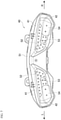
- FIG. 7 is a front view of the rear combination lamp according to the present embodiment.
- FIG. 8 is a sectional view of a part of the vehicle rear portion in FIG. 3 .
- the lamp housing 51 of the rear combination lamp 40 is provided with the pair of lamp portions 41.
- a tail lamp 52, a stop lamp 53, and a turn signal lamp 54 are assembled inside the lens surface 42 of each of the lamp portions 41.
- the tail lamp 52 is formed in an L-shaped region in which one end portion of the lamp portion 41 near the vehicle center and an upper portion of the lamp portion 41 are connected.
- the stop lamp 53 is formed in a lower region adjacent to one end portion of the tail lamp 52.
- the turn signal lamp 54 is formed in a region near a vehicle outer side of the lamp portion 41 adjacent to the tail lamp 52 and the stop lamp 53.
- the tail lamp 52 is turned on in darkness such as in the evening, both the tail lamp 52 and the stop lamp 53 are turned on during braking, and the turn signal lamp 54 is turned on when the vehicle changes its course or turns right or left. Since the tail lamp 52 is most frequently used among the three lamps 52, 53, and 54, the tail lamp 52 is installed at the upper portion of the lamp portion 41 that is separated upward from the undercover 60 (see FIG. 8 ). Since the tail lamp 52 is separated from the undercover 60, a radiation angle of the tail lamp 52 is not narrowed by the undercover 60 and the visibility of the tail lamp 52 is improved.
- the lens surface 42 of the rear combination lamp 40 is inclined rearward from the lower edge 47 toward the upper edge 48. Therefore, the inner space of the lens surface 42 is widened rearward at the upper portion of the lamp portion 41.
- a light emitting portion 55 of the tail lamp 52 can be located further rearward and the undercover 60 can be separated from a radiation range of the tail lamp 52. Since the radiation angle of the tail lamp 52 is sufficiently ensured, it is possible to protrude the undercover 60 further rearward and improve the protection performance of the rear combination lamp 40.
- the stop lamp 53 and the turn signal lamp 54 are installed at a lower portion of the lamp portion 41 close to the undercover 60.
- the upper surface 68 of the undercover 60 is inclined rearward to be separated from the lens surface 42 of the rear combination lamp 40. For this reason, radiation angles of the stop lamp 53 and the turn signal lamp 54 would not be significantly narrowed by the undercover 60. In this way, the visibility of the tail lamp 52, the stop lamp 53, and the turn signal lamp 54 is ensured even when the rear combination lamp 40 is covered by the undercover 60 from below.
- the undercover 60 is provided directly below the lens surface 42 of the rear combination lamp 40.
- the undercover 60 protrudes rearward from the lens surface 42 of the rear combination lamp 40, and a protruding end 69 of the undercover 60 is brought close to the upper edge 48 of the lens surface 42 in the protruding direction. For this reason, in the vehicle bottom view, most of the lens surface 42 of the rear combination lamp 40 is covered by the undercover 60, and the lens surface 42 is protected from mud or the like from below by the undercover 60. In this way, the visibility of the rear combination lamp 40 is ensured and the protection performance of the rear combination lamp 40 is improved.
- the rear combination lamp 40 is covered from below by the undercover 60 along the lower edge of the rear combination lamp 40. Even when the size of the rear fender 29 in the vehicle width direction is smaller than the size of the undercover 60 in the vehicle width direction, the rear combination lamp 40 is protected from mud or the like splashed by the rear wheel 28. By protecting the rear combination lamp 40 with the undercover 60 and reducing the size of the rear fender 29, deterioration of the appearance of the vehicle is prevented and the protection performance of the rear combination lamp 40 is improved.
- the undercover protrudes obliquely downward from the lower edge of the rear surface of the rear combination lamp.
- the undercover may be formed as long as the undercover covers the rear combination lamp from below.
- the undercover may protrude horizontally from the lower edge of the rear surface of the rear combination lamp.
- the undercover covers the entire rear combination lamp.
- the undercover may protect at least the rear surface of the rear combination lamp. For this reason, the foremost position of the undercover may be located in rear of the foremost position of the rear combination lamp, or the front portion of the undercover may not overlap with the rear combination lamp.
- the present embodiment described a rear combination lamp including a pair of left and right lamp portions with a space therebetween.
- the configuration of the rear combination lamp is not particularly limited.
- the present embodiment described an example in which the rear combination lamp, the rear fender, and the undercover are separately formed.
- the rear combination lamp and the undercover may be integrally formed, or the rear fender and the undercover may be integrally formed.
- the protection structure of rear combination lamp according to the present embodiment is not limited to the straddle-type vehicle of a tourer type, and may be adopted by straddle-type vehicles of other types.
- the straddle-type vehicle is not limited to a general vehicle on which a rider rides at a posture of straddling a seat.
- the straddle-type vehicle further includes a scooter-type vehicle on which a rider rides without straddling a seat.
- a protection structure of a rear combination lamp (40) provided at a rear portion of a straddle-type vehicle includes an undercover (60) covering a rear combination lamp from below, and a rear fender (29) covering a rear wheel (28) from above.
- the rear fender is below the undercover.
- the undercover extends along a lower edge of the rear combination lamp.
- a size of the rear fender in a vehicle width direction is smaller than a size of the undercover in the vehicle width direction in a vehicle rear view. According to this configuration, the rear combination lamp is covered from below by the undercover along the lower edge of the rear combination lamp.
- the rear combination lamp is protected from mud or the like splashed by the rear wheel.
- the undercover protrudes obliquely downward from a lower edge (47) of a rear surface (lens surface 42) of the rear combination lamp. According to this configuration, a radiation angle of the rear combination lamp is ensured, and thus it is possible to improve the protection performance of the rear combination lamp without reducing the visibility of the rear combination lamp.
- a foremost position (P1) of the undercover is in front of a foremost position (P2) of the rear combination lamp, and a rearmost position (P3) of the undercover is at the same position as or in front of a rearmost position (P4) of the rear combination lamp in a vehicle side view.
- the rear combination lamp can be entirely protected by the undercover.
- a foremost position of the undercover is in front of a foremost position (P5) of the rear fender in a vehicle side view. According to this configuration, it is possible to reduce the size of the rear fender while protecting the combination lamp.
- a front portion (65) of the undercover overlaps the rear combination lamp in a vehicle side view. According to this configuration, the combination lamp can be protected from mud splash or the like from a lateral side.
- the rear combination lamp includes a pair of left and right lamp portions (41) with a space therebetween.
- the undercover enters between the pair of left and right lamp portions in the vehicle rear view. According to this configuration, since the undercover enters between the pair of ramp portions, mud or the like splashed by the rear wheel is prevented from adhering between the pair of ramp portions.
- a tail lamp (52) of the rear combination lamp is disposed above and apart from the undercover. According to this configuration, since the tail lamp that is frequently used is apart from the undercover, a radiation angle of the tail lamp is ensured and the visibility of the tail lamp is improved. Since the radiation angle of the tail lamp is ensured, the undercover can protrude further rearward and the protection performance of the combination lamp can be improved.
- a frame cover (30) is connected to a front side of the rear combination lamp.
- the rear fender is attached to a lower surface (lower cover 33) of the frame cover in front of the undercover. According to this configuration, it is possible to reduce the size of the rear fender while ensuring an attachment position of the rear fender.
Landscapes
- Engineering & Computer Science (AREA)
- Mechanical Engineering (AREA)
- General Engineering & Computer Science (AREA)
- Physics & Mathematics (AREA)
- Microelectronics & Electronic Packaging (AREA)
- Optics & Photonics (AREA)
- Lighting Device Outwards From Vehicle And Optical Signal (AREA)
Abstract
Description
- The present invention relates to a protection structure of a rear combination lamp.
- A rear combination lamp including a plurality of assembled lamps is generally provided at a rear portion of a straddle-type vehicle such as a motorcycle. In the related art, there has been proposed a structure in which a rear fender is installed below a rear combination lamp to protect the rear combination lamp from mud or the like splashed by a rear wheel (for example, see Patent Literature 1). The rear fender described in
Patent Literature 1 extends rearward from a lower edge of the rear combination lamp and covers an upper side of the rear wheel. With the rear fender, mud or the like is prevented from adhering to the rear combination lamp and visibility of the lamp is ensured. - [Patent Literature 1]
Japanese Patent No. 4104344 - Since the rear combination lamp includes a plurality of integrated lamps, the rear combination lamp has a large size in the vehicle width direction. In order to protect the entire rear combination lamp by the rear fender, it is necessary to increase the size of the rear fender, and the degree of freedom of the shape of the rear fender is also reduced. An increase in the size of the rear fender also deteriorates the appearance of a vehicle.
- The present invention has been made in view of the above circumstance, and an object of the present invention is to provide a protection structure of a rear combination lamp that can improve the protection performance of the rear combination lamp while preventing a decrease in the appearance of a vehicle.
- To solve the problem described above, according to an aspect of the present invention, there is provided a protection structure of a rear combination lamp provided at a rear portion of a straddle-type vehicle. The protection structure of the rear combination lamp includes an undercover covering a rear combination lamp from below, and a rear fender covering a rear wheel from above, the rear fender being below the undercover. The undercover extends along a lower edge of the rear combination lamp. A size of the rear fender in a vehicle width direction is smaller than a size of the undercover in the vehicle width direction in a vehicle rear view.
- According to the protection structure of the rear combination lamp of the aspect of the present invention, the rear combination lamp is covered from below by the undercover along the lower edge of the rear combination lamp. Even when the size of the rear fender in the vehicle width direction is smaller than the size of the undercover in the vehicle width direction, the rear combination lamp is protected from mud or the like splashed by the rear wheel. By protecting the rear combination lamp with the undercover and reducing the size of the rear fender, it is possible to improve the protection performance of the rear combination lamp while preventing deterioration of the appearance of the vehicle.
-
-
FIG. 1 is a left view of a straddle-type vehicle according to a present embodiment. -
FIG. 2 is a perspective view of a vehicle rear portion according to the present embodiment. -
FIG. 3 is a rear view of the vehicle rear portion according to the present embodiment. -
FIG. 4 is a side view of the vehicle rear portion according to the present embodiment. -
FIG. 5 is a perspective view according to the present embodiment in which an upper side of the vehicle rear portion is open. -
FIG. 6 is a bottom view of the vehicle rear portion according to the present embodiment. -
FIG. 7 is a front view of a rear combination lamp according to the present embodiment. -
FIG. 8 is a sectional view of a part of the vehicle rear portion inFIG. 3 . - In a protection structure of a rear combination lamp according to an aspect of the present invention, a rear combination lamp provided at a rear portion of a straddle-type vehicle is covered from below by an undercover along a lower edge of the rear combination lamp. Below the undercover, a rear wheel is covered with a rear fender from above. Even when the size of the rear fender in the vehicle width direction is smaller than the size of the undercover in the vehicle width direction, the rear combination lamp is protected from mud or the like splashed by the rear wheel. By protecting the rear combination lamp with the undercover and reducing the size of the rear fender, it is possible to improve the protection performance of the rear combination lamp while preventing deterioration of the appearance of the vehicle.
- Hereinafter, a present embodiment will be described in detail with reference to the accompanying drawings.
FIG. 1 is a left view of a straddle-type vehicle according to the present embodiment. In the following drawings, an arrow FR indicates a vehicle front side, an arrow RE indicates a vehicle rear side, an arrow L indicates a vehicle left side, and an arrow R indicates a vehicle right side. - As shown in
FIG. 1 , a straddle-type vehicle 1 includes various components such as anengine 16 and an electrical system that are mounted on a twin spar-typevehicle body frame 10 formed by aluminum casting. Thevehicle body frame 10 includes a pair ofmain frames 11 branching from a head pipe (not shown) to the left and right and extending rearward, and a pair of down frames (not shown) branching from the head pipe to the left and right and extending downward. A rear portion of theengine 16 is supported by the pair ofmain frames 11, and a front portion of theengine 16 is supported by the pair of down frames. By supporting theengine 16 with thevehicle body frame 10, the rigidity of the entire vehicle is ensured. - Front portions of the pair of
main frames 11 serve astank rails 12 located above theengine 16, and afuel tank 17 is supported by thetank rails 12. Rear portions of the pair ofmain frames 11 serve asbody frames 13 located in rear of theengine 16, andswing arms 18 are swingably supported in substantially middle positions of thebody frames 13 in the upper-lower direction. Seat rails 14 (seeFIG. 5 ) and a back stay extend rearward from upper portions of thebody frames 13. Arider seat 21 and apillion seat 22 are supported on theseat rails 14 in rear of thefuel tank 17. - A pair of
front forks 23 are steerably supported on the head pipe via a steering shaft (not shown). Afront wheel 25 is rotatably supported by lower portions of thefront forks 23, and an upper portion of thefront wheel 25 is covered with afront fender 26. Theswing arms 18 extend rearward from thebody frames 13. Arear wheel 28 is rotatably supported at rear ends of theswing arms 18, and an upper side of therear wheel 28 is covered with arear fender 29. Theengine 16 is coupled to therear wheel 28 via a chain drive-type speed reduction mechanism, and power from theengine 16 is transmitted to therear wheel 28 via the speed reduction mechanism. - The straddle-
type vehicle 1 is covered with various covers serving as a vehicle body exterior. For example, a vehicle rear portion is covered with aframe cover 30, and arear combination lamp 40 is provided on a rear side of theframe cover 30. Therear combination lamp 40 is located above therear wheel 28, and mud or the like is splashed from therear wheel 28 toward therear combination lamp 40. Although the upper side of therear wheel 28 is covered with therear fender 29, it is difficult for therear fender 29 to prevent mud or the like from adhering to therear combination lamp 40 having a large size in the vehicle width direction. In particular, therear fender 29 tends to be reduced in size from the viewpoint of improving the appearance of a vehicle in recent years. - Although mud or the like can be prevented from adhering to the
rear combination lamp 40 with a large rear fender, the degree of freedom of the shape of the rear fender may reduce, the appearance of the vehicle rear portion may deteriorate, and the weight of the rear fender may increase. Therefore, in the present embodiment, an undercover 60 is attached along a lower edge of therear combination lamp 40 so that therear combination lamp 40 can be protected from mud or the like splashed to therear wheel 28 even when the smallrear fender 29 is used. Therear combination lamp 40 is covered by the undercover 60 from below, and mud or the like is prevented from adhering to therear combination lamp 40. - Hereinafter, a protection structure of a rear combination lamp of the straddle-type vehicle will be described with reference to
FIGS. 2 to 6 .FIG. 2 is a perspective view of the vehicle rear portion according to the present embodiment.FIG. 3 is a rear view of the vehicle rear portion according to the present embodiment.FIG. 4 is a side view of the vehicle rear portion according to the present embodiment.FIG. 5 is a perspective view according to the present embodiment in which an upper side of the vehicle rear portion is opened.FIG. 6 is a bottom view of the vehicle rear portion according to the present embodiment. - As shown in
FIGS. 2 to 4 , the pair of seat rails 14 at the vehicle rear portion are covered by theframe cover 30. Theframe cover 30 includes a pair of side covers 31 covering side portions of the seat rails 14, acenter cover 32 connecting the pair of side covers 31 in rear of thepillion seat 22, and alower cover 33 connecting the pair of side covers 31 below the seat rails 14. Theframe cover 30 is constituted by these upper, lower, left, and right cover members, and therear combination lamp 40 including a plurality of assembled lamps is exposed from an opening on a rear surface side of theframe cover 30. - The
rear combination lamp 40 includes a pair of left andright lamp portions 41 with a space therebetween. Thelamp portions 41 are installed along corresponding lower edges of the side covers 31, and thelamp portions 41 are connected to a rear side of thelower cover 33 in a side view (seeFIG. 4 ), and thereby therear combination lamp 40 and theframe cover 30 are formed in a design having a sense of unity. Each of the pair oflamp portions 41 extends forward from the vicinity of the center of a vehicle rear end and outward in the vehicle width direction. Thelamp portions 41 have large sizes in the vehicle width direction in a vehicle rear view, and thus thelamp portions 41 are easy to be recognized from a vehicle rear side. - The undercover 60 is provided below the
rear combination lamp 40. The undercover 60 protrudes from alens surface 42 of therear combination lamp 40, and therear combination lamp 40 is covered from below by the eaves-shapedundercover 60. The undercover 60 extends along the lower edge of therear combination lamp 40 in a wider range than therear combination lamp 40. The undercover 60 appropriately protects therear combination lamp 40 from mud or the like splashed by therear wheel 28. - The
rear fender 29 is provided below the undercover 60. Therear fender 29 extends in an arch shape along therear wheel 28 in a side view (seeFIG. 4 ), and therear wheel 28 is covered from above by therear fender 29. Therear fender 29 prevents mud from splashing and foreign matters from being caught in therear wheel 28. Therear fender 29 is formed in a triangular shape whose size in the vehicle width direction decreases downward in a rear view (seeFIG. 3 ). Alicense plate lamp 71 is provided at the center of an upper portion of therear fender 29, areflector 72 is provided below thelicense plate lamp 71, and a license plate (not shown) is provided below thereflector 72. - Here, a position relationship among the
rear combination lamp 40, the undercover 60, and therear fender 29 will be described. In the vehicle rear view (seeFIG. 3 ), a size L1 of the undercover 60 in the vehicle width direction is the same as or slightly larger than a size L2 of therear combination lamp 40 in the vehicle width direction. A size L3 of therear fender 29 in the vehicle width direction is smaller than the size L1 of the undercover 60 in the vehicle width direction. Accordingly, even when the size of therear fender 29 in the vehicle width direction is small, therear combination lamp 40 is protected from mud or the like scattering from the vehicle rear side with the undercover 60. - In a vehicle side view (see
FIG. 4 ), a foremost position P1 of the undercover 60 is located forward of a foremost position P2 of therear combination lamp 40, and a rearmost position P3 of the undercover 60 is located in the same position as a rearmost position P4 of therear combination lamp 40 in the front-rear direction. The rearmost position P4 of therear combination lamp 40 is located in the same position as a rear end of therear wheel 28 in the front-rear direction. In the vehicle side view, the foremost position P1 of the undercover 60 is located forward of a foremost position P5 of therear fender 29. Accordingly, even when the size of therear fender 29 in the front-rear direction is small, therear combination lamp 40 is protected from mud or the like scattering from vehicle side portions with the undercover 60. - In the present embodiment, that sizes in the vehicle width direction are the same is not limited to that the sizes are completely equal, and may include an error to such an extent that the sizes can be regarded as substantially equal. In the present embodiment, the same position in the front-rear direction is not limited to being completely the same position, and may include an error to such an extent that the position can be regarded as substantially the same. In the present embodiment, the rearmost position P3 of the undercover 60 is located in the same position in the front-rear direction as the rearmost position P4 of the
rear combination lamp 40. Alternatively, the rearmost position P3 of the undercover 60 may be located forward of the rearmost position P4 of therear combination lamp 40. - In the vehicle side view, a
front portion 65 of the undercover 60 has a large size in the upper-lower direction, and anupper edge 66 of thefront portion 65 of the undercover 60 is formed in a gentle mountain shape. Thefront portion 65 of the undercover 60 slightly overlaps with alower edge 46 of afront portion 45 of therear combination lamp 40. Thefront portion 65 of the undercover 60 does not protrude outward in the vehicle width direction in an eaves shape, and covers thelower edge 46 of thefront portion 45 of therear combination lamp 40 from the outside. For this reason, thefront portion 45 of therear combination lamp 40 is protected from mud or the like scattering toward thefront portion 45 of therear combination lamp 40. - As described above, in the vehicle rear view (see
FIG. 3 ), the pair oflamp portions 41 of therear combination lamp 40 are spaced apart from each other in the vehicle width direction with a space therebetween. The space between the pair oflamp portions 41 is recessed, and thus it is difficult to remove mud and the like adhering to the recess. Further, mud or the like may spread from the recess to the periphery and adhere to thelamp portions 41. Although it is also conceivable to connect the pair oflamp portions 41 to eliminate the recess, the design of therear combination lamp 40 would deteriorate. Therefore, acentral portion 67 of the undercover 60 enters between the pair oflamp portions 41, and mud or the like is prevented from adhering between the pair oflamp portions 41 with thecentral portion 67. - In this way, the undercover 60 has a function of protecting the
rear combination lamp 40, thereby reducing the size of therear fender 29. At this time, the undercover 60 is formed in an elongated shape between therear combination lamp 40 and therear fender 29, and is inconspicuous in the vehicle rear view and the vehicle side view. Since therear fender 29 is miniaturized and the undercover 60 has a small influence on the appearance of the vehicle, the protection performance of therear combination lamp 40 is improved while preventing the deterioration of the appearance of the vehicle. The degree of freedom of the shape of therear fender 29 is also ensured. - Further, in the vehicle side view (see
FIG. 4 ), thelens surface 42 of therear combination lamp 40 is inclined rearward from a lower edge toward an upper edge. Anupper surface 68 of the undercover 60 is connected to the lower edge of thelens surface 42 of therear combination lamp 40, and is inclined rearward from an upper edge toward a lower edge in the vehicle side view. In this way, the undercover 60 protrudes obliquely downward from the lower edge of thelens surface 42 of therear combination lamp 40, and thus a radiation angle of therear combination lamp 40 is ensured. Therefore, the protection performance of therear combination lamp 40 is improved without reducing the visibility of therear combination lamp 40. - Next, attachment configurations of members will be described. As shown in
FIG. 5 , arear fender brace 35 is attached to rear ends of the pair of seat rails 14, and an arch-shapedsupport frame 36 is attached to therear fender brace 35. Alamp housing 51 of therear combination lamp 40 is attached to thesupport frame 36, and the lens surface 42 (seeFIG. 2 ) of therear combination lamp 40 is exposed to the outside from thelower cover 33. Below thelamp housing 51, the undercover 60 (seeFIG. 2 ) is screwed to thelower cover 33 from the inside so that a screw head is prevented from exposure to the outside. - As shown in
FIG. 6 , therear fender 29 is screwed to thelower cover 33 from below bybolts 75 in positions forward of the undercover 60. An attachment portion of therear fender 29 is wide in the vehicle width direction, and a main body portion of therear fender 29 is formed in a triangular shape. For this reason, it is possible to make the triangular exposed portion of therear fender 29 slim while ensuring a wide attachment portion of therear fender 29. Since therear fender 29 is not attached to the undercover 60, the size of the undercover 60 can be reduced. In a vehicle bottom view, therear combination lamp 40 is exposed to the outside of the undercover 60. - The relationship between the radiation angle of the rear combination lamp and the undercover will be described with reference to
FIGS. 7 and8 .FIG. 7 is a front view of the rear combination lamp according to the present embodiment.FIG. 8 is a sectional view of a part of the vehicle rear portion inFIG. 3 . - As shown in
FIG. 7 , thelamp housing 51 of therear combination lamp 40 is provided with the pair oflamp portions 41. Atail lamp 52, astop lamp 53, and aturn signal lamp 54 are assembled inside thelens surface 42 of each of thelamp portions 41. Thetail lamp 52 is formed in an L-shaped region in which one end portion of thelamp portion 41 near the vehicle center and an upper portion of thelamp portion 41 are connected. Thestop lamp 53 is formed in a lower region adjacent to one end portion of thetail lamp 52. Theturn signal lamp 54 is formed in a region near a vehicle outer side of thelamp portion 41 adjacent to thetail lamp 52 and thestop lamp 53. - The
tail lamp 52 is turned on in darkness such as in the evening, both thetail lamp 52 and thestop lamp 53 are turned on during braking, and theturn signal lamp 54 is turned on when the vehicle changes its course or turns right or left. Since thetail lamp 52 is most frequently used among the threelamps tail lamp 52 is installed at the upper portion of thelamp portion 41 that is separated upward from the undercover 60 (seeFIG. 8 ). Since thetail lamp 52 is separated from the undercover 60, a radiation angle of thetail lamp 52 is not narrowed by the undercover 60 and the visibility of thetail lamp 52 is improved. - More specifically, as shown in
FIG. 8 , thelens surface 42 of therear combination lamp 40 is inclined rearward from thelower edge 47 toward theupper edge 48. Therefore, the inner space of thelens surface 42 is widened rearward at the upper portion of thelamp portion 41. By installing thetail lamp 52 at the upper portion of thelamp portion 41, alight emitting portion 55 of thetail lamp 52 can be located further rearward and the undercover 60 can be separated from a radiation range of thetail lamp 52. Since the radiation angle of thetail lamp 52 is sufficiently ensured, it is possible to protrude the undercover 60 further rearward and improve the protection performance of therear combination lamp 40. - The
stop lamp 53 and the turn signal lamp 54 (seeFIG. 7 ) are installed at a lower portion of thelamp portion 41 close to the undercover 60. However, theupper surface 68 of the undercover 60 is inclined rearward to be separated from thelens surface 42 of therear combination lamp 40. For this reason, radiation angles of thestop lamp 53 and theturn signal lamp 54 would not be significantly narrowed by the undercover 60. In this way, the visibility of thetail lamp 52, thestop lamp 53, and theturn signal lamp 54 is ensured even when therear combination lamp 40 is covered by the undercover 60 from below. - The undercover 60 is provided directly below the
lens surface 42 of therear combination lamp 40. The undercover 60 protrudes rearward from thelens surface 42 of therear combination lamp 40, and aprotruding end 69 of the undercover 60 is brought close to theupper edge 48 of thelens surface 42 in the protruding direction. For this reason, in the vehicle bottom view, most of thelens surface 42 of therear combination lamp 40 is covered by the undercover 60, and thelens surface 42 is protected from mud or the like from below by the undercover 60. In this way, the visibility of therear combination lamp 40 is ensured and the protection performance of therear combination lamp 40 is improved. - As described above, according to the present embodiment, the
rear combination lamp 40 is covered from below by the undercover 60 along the lower edge of therear combination lamp 40. Even when the size of therear fender 29 in the vehicle width direction is smaller than the size of the undercover 60 in the vehicle width direction, therear combination lamp 40 is protected from mud or the like splashed by therear wheel 28. By protecting therear combination lamp 40 with the undercover 60 and reducing the size of therear fender 29, deterioration of the appearance of the vehicle is prevented and the protection performance of therear combination lamp 40 is improved. - In the present embodiment, the undercover protrudes obliquely downward from the lower edge of the rear surface of the rear combination lamp. However, the undercover may be formed as long as the undercover covers the rear combination lamp from below. For example, the undercover may protrude horizontally from the lower edge of the rear surface of the rear combination lamp.
- In the present embodiment, the undercover covers the entire rear combination lamp. Alternatively, the undercover may protect at least the rear surface of the rear combination lamp. For this reason, the foremost position of the undercover may be located in rear of the foremost position of the rear combination lamp, or the front portion of the undercover may not overlap with the rear combination lamp.
- The present embodiment described a rear combination lamp including a pair of left and right lamp portions with a space therebetween. However, the configuration of the rear combination lamp is not particularly limited.
- The present embodiment described an example in which the rear combination lamp, the rear fender, and the undercover are separately formed. Alternatively, the rear combination lamp and the undercover may be integrally formed, or the rear fender and the undercover may be integrally formed.
- The protection structure of rear combination lamp according to the present embodiment is not limited to the straddle-type vehicle of a tourer type, and may be adopted by straddle-type vehicles of other types. The straddle-type vehicle is not limited to a general vehicle on which a rider rides at a posture of straddling a seat. The straddle-type vehicle further includes a scooter-type vehicle on which a rider rides without straddling a seat.
- As described above, according to the present embodiment, there is provided a protection structure of a rear combination lamp (40) provided at a rear portion of a straddle-type vehicle. The protection structure of the rear combination lamp includes an undercover (60) covering a rear combination lamp from below, and a rear fender (29) covering a rear wheel (28) from above. The rear fender is below the undercover. The undercover extends along a lower edge of the rear combination lamp. A size of the rear fender in a vehicle width direction is smaller than a size of the undercover in the vehicle width direction in a vehicle rear view. According to this configuration, the rear combination lamp is covered from below by the undercover along the lower edge of the rear combination lamp. Even when the size of the rear fender in the vehicle width direction is smaller than the size of the undercover in the vehicle width direction, the rear combination lamp is protected from mud or the like splashed by the rear wheel. By protecting the rear combination lamp with the undercover and reducing the size of the rear fender, it is possible to improve the protection performance of the rear combination lamp while preventing deterioration of the appearance of the vehicle.
- In the protection structure of the rear combination lamp according to the present embodiment, the undercover protrudes obliquely downward from a lower edge (47) of a rear surface (lens surface 42) of the rear combination lamp. According to this configuration, a radiation angle of the rear combination lamp is ensured, and thus it is possible to improve the protection performance of the rear combination lamp without reducing the visibility of the rear combination lamp.
- In the protection structure of the rear combination lamp according to the present embodiment, a foremost position (P1) of the undercover is in front of a foremost position (P2) of the rear combination lamp, and a rearmost position (P3) of the undercover is at the same position as or in front of a rearmost position (P4) of the rear combination lamp in a vehicle side view. According to this configuration, the rear combination lamp can be entirely protected by the undercover.
- In the protection structure of the rear combination lamp according to the present embodiment, a foremost position of the undercover is in front of a foremost position (P5) of the rear fender in a vehicle side view. According to this configuration, it is possible to reduce the size of the rear fender while protecting the combination lamp.
- In the protection structure of the rear combination lamp according to the present embodiment, a front portion (65) of the undercover overlaps the rear combination lamp in a vehicle side view. According to this configuration, the combination lamp can be protected from mud splash or the like from a lateral side.
- In the protection structure of the rear combination lamp according to the present embodiment, the rear combination lamp includes a pair of left and right lamp portions (41) with a space therebetween. The undercover enters between the pair of left and right lamp portions in the vehicle rear view. According to this configuration, since the undercover enters between the pair of ramp portions, mud or the like splashed by the rear wheel is prevented from adhering between the pair of ramp portions.
- In the protection structure of the rear combination lamp according to the present embodiment, a tail lamp (52) of the rear combination lamp is disposed above and apart from the undercover. According to this configuration, since the tail lamp that is frequently used is apart from the undercover, a radiation angle of the tail lamp is ensured and the visibility of the tail lamp is improved. Since the radiation angle of the tail lamp is ensured, the undercover can protrude further rearward and the protection performance of the combination lamp can be improved.
- In the protection structure of the rear combination lamp according to the present embodiment, a frame cover (30) is connected to a front side of the rear combination lamp. The rear fender is attached to a lower surface (lower cover 33) of the frame cover in front of the undercover. According to this configuration, it is possible to reduce the size of the rear fender while ensuring an attachment position of the rear fender.
- Although the present embodiment has been described, the above-described embodiment and modifications may be combined entirely or partially as other embodiment.
- The technique of the present invention is not limited to the above-described embodiment, and various changes, substitutions, and modifications may be made without departing from the spirit of the technical idea of the present invention. The present invention may be implemented using other methods as long as the technical concept can be implemented by the methods through advance of the technology or other derivative technology. Therefore, the claims cover all embodiments that may be included within the scope of the technical concept.
-
- 1
- Straddle-type vehicle
- 29
- Rear fender
- 30
- Frame cover
- 33
- Lower cover (Lower surface of the frame cover)
- 40
- Rear combination lamp
- 41
- Lamp portion
- 42
- Lens surface (Rear surface of the rear combination lamp)
- 47
- Lower edge of the lens surface
- 52
- Tail lamp
- 60
- Undercover
- 65
- Front portion of the undercover
Claims (8)
- A protection structure of a rear combination lamp (40) provided at a rear portion of a straddle-type vehicle (1), the protection structure of the rear combination lamp (40) comprising:an undercover (60) covering the rear combination lamp (40) from below; anda rear fender (29) covering a rear wheel from above, the rear fender (29) being below the undercover (60),wherein the undercover (60) extends along a lower edge of the rear combination lamp (40), andwherein a size of the rear fender (29) in a vehicle width direction is smaller than a size of the undercover (60) in the vehicle width direction in a vehicle rear view.
- The protection structure of the rear combination lamp (40) according to claim 1, wherein the undercover (60) protrudes obliquely downward from a lower edge of a rear surface (42) of the rear combination lamp (40).
- The protection structure of the rear combination lamp (40) according to claim 1 or 2, wherein a foremost position of the undercover (60) is in front of a foremost position of the rear combination lamp (40), and a rearmost position of the undercover (60) is at the same position as or in front of a rearmost position of the rear combination lamp (40), in a vehicle side view.
- The protection structure of the rear combination lamp (40) according to any one of claims 1 to 3, wherein a foremost position of the undercover (60) is in front of a foremost position of the rear fender (29) in a vehicle side view.
- The protection structure of the rear combination lamp (40) according to any one of claims 1 to 4, wherein a front portion of the undercover (60) overlaps with the rear combination lamp (40) in a vehicle side view.
- The protection structure of the rear combination lamp (40) according to any one of claims 1 to 5,wherein the rear combination lamp (40) includes a pair of left and right lamp portions (41) with a space therebetween, andwherein the undercover (60) enters between the pair of left and right lamp portions (41) in the vehicle rear view.
- The protection structure of the rear combination lamp (40) according to any one of claims 1 to 6, wherein a tail lamp (52) of the rear combination lamp (40) is disposed above and apart from the undercover (60).
- The protection structure of the rear combination lamp (40) according to any one of claims 1 to 7, wherein a frame cover (30) is connected to a front side of the rear combination lamp (40), and the rear fender (29) is attached to a lower surface (33) of the frame cover (30) in front of the undercover (60).
Applications Claiming Priority (1)
| Application Number | Priority Date | Filing Date | Title |
|---|---|---|---|
| JP2020134389A JP7581695B2 (en) | 2020-08-07 | 2020-08-07 | Rear combination lamp protection structure |
Publications (1)
| Publication Number | Publication Date |
|---|---|
| EP3950472A1 true EP3950472A1 (en) | 2022-02-09 |
Family
ID=77179940
Family Applications (1)
| Application Number | Title | Priority Date | Filing Date |
|---|---|---|---|
| EP21189237.7A Pending EP3950472A1 (en) | 2020-08-07 | 2021-08-02 | Protection structure of rear combination lamp |
Country Status (3)
| Country | Link |
|---|---|
| US (1) | US11371674B2 (en) |
| EP (1) | EP3950472A1 (en) |
| JP (1) | JP7581695B2 (en) |
Families Citing this family (2)
| Publication number | Priority date | Publication date | Assignee | Title |
|---|---|---|---|---|
| JP7517026B2 (en) * | 2020-09-24 | 2024-07-17 | スズキ株式会社 | Front fender |
| EP4327831A4 (en) | 2021-04-20 | 2026-02-11 | Nihon Mediphysics Co Ltd | RADIOACTIVE COMPLEX OF ANTI-CD20 ANTIBODIES AND RADIOPHARMACEUTICAL |
Citations (3)
| Publication number | Priority date | Publication date | Assignee | Title |
|---|---|---|---|---|
| JP2002029475A (en) * | 2000-07-14 | 2002-01-29 | Yamaha Motor Co Ltd | Rear fender for motorcycle |
| JP2004074915A (en) * | 2002-08-16 | 2004-03-11 | Honda Motor Co Ltd | Lighting support system for motorcycles |
| TW201339037A (en) * | 2012-03-30 | 2013-10-01 | Yamaha Motor Co Ltd | Straddle-type vehicle |
Family Cites Families (9)
| Publication number | Priority date | Publication date | Assignee | Title |
|---|---|---|---|---|
| JP4104344B2 (en) * | 2002-02-20 | 2008-06-18 | 本田技研工業株式会社 | Rear combination lamp mounting structure for motorcycles |
| JP4469701B2 (en) * | 2004-11-05 | 2010-05-26 | ヤマハ発動機株式会社 | Saddle riding vehicle |
| JP5022168B2 (en) * | 2007-10-10 | 2012-09-12 | 本田技研工業株式会社 | Motorcycle tail light unit |
| JP2009107565A (en) * | 2007-10-31 | 2009-05-21 | Yamaha Motor Co Ltd | Motorcycle |
| CN103358986B (en) * | 2012-03-30 | 2015-09-16 | 雅马哈发动机株式会社 | Straddle type vehicle |
| CA2924948C (en) * | 2013-09-27 | 2018-01-09 | Honda Motor Co., Ltd. | Two-wheeled motor vehicle |
| JP6661687B2 (en) * | 2018-03-20 | 2020-03-11 | 本田技研工業株式会社 | Saddle-type vehicle |
| JP6779952B2 (en) * | 2018-09-21 | 2020-11-04 | 本田技研工業株式会社 | Light structure of saddle-riding vehicle |
| CN112519944A (en) * | 2020-12-23 | 2021-03-19 | 常州豪爵铃木摩托车有限公司 | Motorcycle tail structure and motorcycle |
-
2020
- 2020-08-07 JP JP2020134389A patent/JP7581695B2/en active Active
-
2021
- 2021-07-29 US US17/388,768 patent/US11371674B2/en active Active
- 2021-08-02 EP EP21189237.7A patent/EP3950472A1/en active Pending
Patent Citations (3)
| Publication number | Priority date | Publication date | Assignee | Title |
|---|---|---|---|---|
| JP2002029475A (en) * | 2000-07-14 | 2002-01-29 | Yamaha Motor Co Ltd | Rear fender for motorcycle |
| JP2004074915A (en) * | 2002-08-16 | 2004-03-11 | Honda Motor Co Ltd | Lighting support system for motorcycles |
| TW201339037A (en) * | 2012-03-30 | 2013-10-01 | Yamaha Motor Co Ltd | Straddle-type vehicle |
Also Published As
| Publication number | Publication date |
|---|---|
| JP7581695B2 (en) | 2024-11-13 |
| US11371674B2 (en) | 2022-06-28 |
| JP2022030389A (en) | 2022-02-18 |
| US20220042667A1 (en) | 2022-02-10 |
Similar Documents
| Publication | Publication Date | Title |
|---|---|---|
| US9902313B2 (en) | Two-wheeled motor vehicle | |
| US7798509B2 (en) | Vehicle motorcycle light unit having lens | |
| US7651112B2 (en) | Motorcycle with grab bar attached to body frame below seat | |
| US7762609B2 (en) | Straddle-type vehicle | |
| US11407464B2 (en) | Front structure of saddle riding vehicle | |
| EP2080695B1 (en) | Flasher and straddle-type vehicle | |
| US11371674B2 (en) | Protection structure of rear combination lamp | |
| US8317212B2 (en) | Motorcycle including bendable rear fender | |
| CN102700658A (en) | Saddle riding type vehicle | |
| EP2161187B1 (en) | Motorcycle | |
| US10871267B2 (en) | Lamp body structure for saddle riding vehicle | |
| BRPI0901522A2 (en) | support structure of the front portion of the vehicle body | |
| CN103707964A (en) | Motorcycle | |
| JP2020069875A (en) | Saddle-type electric vehicle | |
| CN110450892B (en) | Automatic two-wheel vehicle | |
| BRPI1104638B1 (en) | motorcycle rear frame | |
| JPH10226375A (en) | Scooter type motorcycle | |
| US20220250702A1 (en) | Front fairing for a scooter | |
| JPWO2005016733A1 (en) | Front fenders and motorcycles for motorcycles | |
| KR100729469B1 (en) | Lamp structure for motorcycle | |
| JP2535299B2 (en) | Motorcycle with frame protection device | |
| EP3964432A1 (en) | Front cowl | |
| JP6207098B2 (en) | Motorcycle body cover and motorcycle | |
| TWI606951B (en) | Straddle type vehicle | |
| US20240313417A1 (en) | Corner reflector installation structure |
Legal Events
| Date | Code | Title | Description |
|---|---|---|---|
| PUAI | Public reference made under article 153(3) epc to a published international application that has entered the european phase |
Free format text: ORIGINAL CODE: 0009012 |
|
| STAA | Information on the status of an ep patent application or granted ep patent |
Free format text: STATUS: REQUEST FOR EXAMINATION WAS MADE |
|
| 17P | Request for examination filed |
Effective date: 20210802 |
|
| AK | Designated contracting states |
Kind code of ref document: A1 Designated state(s): AL AT BE BG CH CY CZ DE DK EE ES FI FR GB GR HR HU IE IS IT LI LT LU LV MC MK MT NL NO PL PT RO RS SE SI SK SM TR |
|
| STAA | Information on the status of an ep patent application or granted ep patent |
Free format text: STATUS: EXAMINATION IS IN PROGRESS |
|
| 17Q | First examination report despatched |
Effective date: 20240403 |
|
| GRAP | Despatch of communication of intention to grant a patent |
Free format text: ORIGINAL CODE: EPIDOSNIGR1 |
|
| STAA | Information on the status of an ep patent application or granted ep patent |
Free format text: STATUS: GRANT OF PATENT IS INTENDED |
|
| RIC1 | Information provided on ipc code assigned before grant |
Ipc: B62J 6/04 20200101AFI20251013BHEP Ipc: B62J 15/00 20060101ALI20251013BHEP Ipc: B62J 17/00 20200101ALI20251013BHEP Ipc: F21S 43/14 20180101ALI20251013BHEP Ipc: B60Q 1/26 20060101ALI20251013BHEP |
|
| INTG | Intention to grant announced |
Effective date: 20251114 |
|
| GRAJ | Information related to disapproval of communication of intention to grant by the applicant or resumption of examination proceedings by the epo deleted |
Free format text: ORIGINAL CODE: EPIDOSDIGR1 |
|
| STAA | Information on the status of an ep patent application or granted ep patent |
Free format text: STATUS: EXAMINATION IS IN PROGRESS |
|
| GRAP | Despatch of communication of intention to grant a patent |
Free format text: ORIGINAL CODE: EPIDOSNIGR1 |
|
| STAA | Information on the status of an ep patent application or granted ep patent |
Free format text: STATUS: GRANT OF PATENT IS INTENDED |
|
| INTC | Intention to grant announced (deleted) | ||
| INTG | Intention to grant announced |
Effective date: 20260309 |