EP3950417A1 - Side to side tilting aircraft seat mechanism - Google Patents
Side to side tilting aircraft seat mechanism Download PDFInfo
- Publication number
- EP3950417A1 EP3950417A1 EP21189630.3A EP21189630A EP3950417A1 EP 3950417 A1 EP3950417 A1 EP 3950417A1 EP 21189630 A EP21189630 A EP 21189630A EP 3950417 A1 EP3950417 A1 EP 3950417A1
- Authority
- EP
- European Patent Office
- Prior art keywords
- aircraft seat
- tilting
- linkage
- tilt
- stationary support
- Prior art date
- Legal status (The legal status is an assumption and is not a legal conclusion. Google has not performed a legal analysis and makes no representation as to the accuracy of the status listed.)
- Granted
Links
Images




Classifications
-
- B—PERFORMING OPERATIONS; TRANSPORTING
- B64—AIRCRAFT; AVIATION; COSMONAUTICS
- B64D—EQUIPMENT FOR FITTING IN OR TO AIRCRAFT; FLIGHT SUITS; PARACHUTES; ARRANGEMENT OR MOUNTING OF POWER PLANTS OR PROPULSION TRANSMISSIONS IN AIRCRAFT
- B64D11/00—Passenger or crew accommodation; Flight-deck installations not otherwise provided for
- B64D11/06—Arrangements of seats, or adaptations or details specially adapted for aircraft seats
- B64D11/0639—Arrangements of seats, or adaptations or details specially adapted for aircraft seats with features for adjustment or converting of seats
- B64D11/064—Adjustable inclination or position of seats
-
- B—PERFORMING OPERATIONS; TRANSPORTING
- B60—VEHICLES IN GENERAL
- B60N—SEATS SPECIALLY ADAPTED FOR VEHICLES; VEHICLE PASSENGER ACCOMMODATION NOT OTHERWISE PROVIDED FOR
- B60N2/00—Seats specially adapted for vehicles; Arrangement or mounting of seats in vehicles
- B60N2/02—Seats specially adapted for vehicles; Arrangement or mounting of seats in vehicles the seat or part thereof being movable, e.g. adjustable
- B60N2/04—Seats specially adapted for vehicles; Arrangement or mounting of seats in vehicles the seat or part thereof being movable, e.g. adjustable the whole seat being movable
- B60N2/10—Seats specially adapted for vehicles; Arrangement or mounting of seats in vehicles the seat or part thereof being movable, e.g. adjustable the whole seat being movable tiltable
-
- B—PERFORMING OPERATIONS; TRANSPORTING
- B64—AIRCRAFT; AVIATION; COSMONAUTICS
- B64D—EQUIPMENT FOR FITTING IN OR TO AIRCRAFT; FLIGHT SUITS; PARACHUTES; ARRANGEMENT OR MOUNTING OF POWER PLANTS OR PROPULSION TRANSMISSIONS IN AIRCRAFT
- B64D11/00—Passenger or crew accommodation; Flight-deck installations not otherwise provided for
- B64D11/06—Arrangements of seats, or adaptations or details specially adapted for aircraft seats
- B64D11/0648—Lower frame constructions
-
- B—PERFORMING OPERATIONS; TRANSPORTING
- B64—AIRCRAFT; AVIATION; COSMONAUTICS
- B64D—EQUIPMENT FOR FITTING IN OR TO AIRCRAFT; FLIGHT SUITS; PARACHUTES; ARRANGEMENT OR MOUNTING OF POWER PLANTS OR PROPULSION TRANSMISSIONS IN AIRCRAFT
- B64D11/00—Passenger or crew accommodation; Flight-deck installations not otherwise provided for
- B64D11/06—Arrangements of seats, or adaptations or details specially adapted for aircraft seats
- B64D11/0691—Arrangements of seats, or adaptations or details specially adapted for aircraft seats specially adapted for cabin crew
Definitions
- Aircraft seating configurations such as for certain military aircraft, may be oriented with crew member seats facing the side of the aircraft.
- crew members are oriented with the side of their bodies (left or right) facing the direction of aircraft travel.
- crew members may be placed in uncomfortable stress positions of supporting their weight against a lateral force with no or limited support.
- inventions of the inventive concepts disclosed herein are directed to an aircraft seat with infinitely adjustable, lateral tilt control within a specified range.
- the aircraft seat includes a stationary support, a tilting frame rotatably or translatably attached to the stationary base, and a tilt control mechanism to adjust the tilt within the defined range and positively lock the frame without back-driving.
- the tilt control mechanism comprises a plurality of linkages connected to the stationary support and the tilting frame, and to each other via a threaded block.
- the threaded block is translated via a threaded shaft to adjust the linkages and thereby adjust the tilt.
- the tilt control mechanism comprises a curved rack and a pinion.
- the threaded block and threaded shaft, or the rack and pinion define ACME threads to prevent back-driving.
- inventive concepts are not limited in their application to the details of construction and the arrangement of the components or steps or methodologies set forth in the following description or illustrated in the drawings.
- inventive concepts disclosed herein may be practiced without these specific details.
- well-known features may not be described in detail to avoid unnecessarily complicating the instant disclosure.
- inventive concepts disclosed herein are capable of other embodiments or of being practiced or carried out in various ways. Also, it is to be understood that the phraseology and terminology employed herein is for the purpose of description and should not be regarded as limiting.
- a letter following a reference numeral is intended to reference an embodiment of the feature or element that may be similar, but not necessarily identical, to a previously described element or feature bearing the same reference numeral (e.g., 1, 1a, 1b).
- reference numeral e.g. 1, 1a, 1b
- Such shorthand notations are used for purposes of convenience only, and should not be construed to limit the inventive concepts disclosed herein in any way unless expressly stated to the contrary.
- any reference to "one embodiment,” or “some embodiments” means that a particular element, feature, structure, or characteristic described in connection with the embodiment is included in at least one embodiment of the inventive concepts disclosed herein.
- the appearances of the phrase “in some embodiments” in various places in the specification are not necessarily all referring to the same embodiment, and embodiments of the inventive concepts disclosed may include one or more of the features expressly described or inherently present herein, or any combination of sub-combination of two or more such features, along with any other features which may not necessarily be expressly described or inherently present in the instant disclosure.
- inventions of the inventive concepts disclosed herein are directed to an aircraft seat with infinitely adjustable, lateral tilt control within a specified range.
- the aircraft seat includes a stationary support, a tilting frame rotatably or translatably attached to the stationary base, and a tilt control mechanism to adjust the tilt within the defined range and positively lock the frame without back-driving.
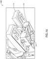
- FIGS. 1A-1C a perspective view of an aircraft seat 100, and front and partial exploded views of an aircraft seat frame 104 according to an exemplary embodiment are shown.
- the aircraft seat 100 comprises a stationary support 102 that may be affixed the aircraft.
- a separate frame 104 is attached to the stationary support 102 via one or more connection elements 106 that allows rotation or angular translation of the frame 104 with respect to the stationary support 102.
- connection elements 106 may comprise a bolt, trunnion, or other pivotable element.
- the connection elements 106 may comprise one or more trunnions 110 or rollers disposed to travel within a curved channel 116.
- the frame 104 may define a curved channel 116 and the stationary support 106 may include the one or more trunnions 110 or rollers. The frame 104 would move within a range defined by gaps between the lateral edges of the curved channel 116 and the nearest trunnion 110 or roller.
- the stationary support 106 may also include one or more support elements 108 that at least partially support the load of the frame 104 and attached seat 114.
- a cover plate 112 may be disposed to conceal and protect the connection element 106.
- the support elements 108 provide secondary off-loading features in the event that the downward load on stationary support 102 becomes so great that the rollers 110 begin to bend and need additional support to prevent frame 104 from losing engagement to stationary support 102. During normal use, the support elements 108 would not contact surfaces of the curved channel 116. Back-driving prevention is accomplished in part by the friction between the rack and pinion.
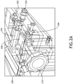
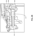
- FIGS. 2A-2C a partial, perspective view; and a front, partial, cross-sectional view of an aircraft seat tilting control mechanism; and a perspective view of an aircraft seat according to an exemplary embodiment are shown.
- the aircraft seat includes a stationary support 200 affixed to the aircraft and a frame 202 connected to the stationary support 200 via one or more connection elements 220 configured to allow rotation or angular translation
- the frame 202 may be infinitely adjustable within a range of tilting angles via a tilt control mechanism.
- the tilt control mechanism may comprise a system having a first linkage 204 connected to the frame 202 at a first end, a second linkage 206 connected to the stationary support 200 at a first end, and a threaded block 208 connected to both the first linkage 204 at a second end and the second linkage 206 at a second end.
- a rotatable control shaft 210 having a threaded portion 212 configured to engage the threaded block 208 may be held in a fixed position relative to the stationary support 200. As the control shaft 210 is rotated (for example, via a knob), the threaded block 208 is translated linearly, thereby increasing or decreasing the distance between the first ends of the first linkage 204 and the second linkage 206. Because the first linkage 204 and second linkage 206 are disposed some distance from the connection element 220, the distance between the first ends corresponds to a tilt angle.
- the threaded block 208 and threaded portion 212 of the control shaft 210 define trapezoidal ACME threads.
- ACME threads provide a thread angle that prevents back-driving via increased friction between thread flanks.
- certain aircraft seat controls 216 are fixed relative to the stationary support 200 but also need to pass through the frame 202.
- Each such aircraft seat control 216 may correspond to an elongated opening 214, 218 in the frame 202 to allow the frame 202 to move within the defined range around the aircraft seat controls 216.
- FIGS. 3A-3C perspective views and a front, cross-sectional view of an aircraft seat tilting control mechanism according to an exemplary embodiment are shown.
- the aircraft seat includes a stationary support 300 affixed to the aircraft and a frame 302 connected to the stationary support 300 via one or more connection elements 320, each comprising a curved channel defined by the frame 302 and one or more rollers affixed to the stationary support 300
- the frame 302 may be infinitely adjustable within a range of tilting angles via a tilt control mechanism.
- connection elements 320 connect the stationary support 300 to the frame 302; a first connection 320 disposed at a front interface and a second connection element 320 disposed at a rear interface, both configured to move about the same axis.
- the tilt range of the frame 302 is defined by a gap between the lateral termini of the curved channel and the nearest corresponding roller.
- the tilt control mechanism may comprise a curved rack 304 and a control shaft 310 having a corresponding pinion 306.
- the curved rack 304 is affixed to the stationary support 300 and the control shaft 310 is rotatably affixed to the frame 302 via one or more shaft supports 308 such that the pinion 306 is maintained in contact with the rack 304 over the entire tilt range as defined by the connection element 320.
- the tilt angle may be set by turning the control shaft 310 via a knob or some other adjusting mechanism.
- the rack 304 and pinion 306 define trapezoidal ACME threads.
- ACME threads provide a thread angle that prevents back-driving via increased friction between thread flanks.
- the pinion lead is no more than thirty-three percent (33%) of the pinion diameter; such ratio prevents undesirable back-driving.
- Embodiments of the present disclosure allow the aircraft seat to tilt in the opposite direction of the pitching direction to compensate and keep the crew member level.
Landscapes
- Engineering & Computer Science (AREA)
- Aviation & Aerospace Engineering (AREA)
- Transportation (AREA)
- Mechanical Engineering (AREA)
- Seats For Vehicles (AREA)
- Chairs For Special Purposes, Such As Reclining Chairs (AREA)
Abstract
Description
- Aircraft seating configurations, such as for certain military aircraft, may be oriented with crew member seats facing the side of the aircraft. In such situations, crew members are oriented with the side of their bodies (left or right) facing the direction of aircraft travel. As the aircraft pitches up and down, crew members may be placed in uncomfortable stress positions of supporting their weight against a lateral force with no or limited support.
- In one aspect, embodiments of the inventive concepts disclosed herein are directed to an aircraft seat with infinitely adjustable, lateral tilt control within a specified range. The aircraft seat includes a stationary support, a tilting frame rotatably or translatably attached to the stationary base, and a tilt control mechanism to adjust the tilt within the defined range and positively lock the frame without back-driving.
- In a further aspect, the tilt control mechanism comprises a plurality of linkages connected to the stationary support and the tilting frame, and to each other via a threaded block. The threaded block is translated via a threaded shaft to adjust the linkages and thereby adjust the tilt. Alternatively, the tilt control mechanism comprises a curved rack and a pinion.
- In a further aspect, the threaded block and threaded shaft, or the rack and pinion define ACME threads to prevent back-driving.
- It is to be understood that both the foregoing general description and the following detailed description are exemplary and explanatory only and should not restrict the scope of the claims. The accompanying drawings, which are incorporated in and constitute a part of the specification, illustrate exemplary embodiments of the inventive concepts disclosed herein and together with the general description, serve to explain the principles.
- The numerous advantages of the embodiments of the inventive concepts disclosed herein may be better understood by those skilled in the art by reference to the accompanying figures in which:
-
FIG. 1A shows a perspective view of an aircraft seat according to an exemplary embodiment; -
FIG. 1B shows a front view of an aircraft seat frame according to an exemplary embodiment; -
FIG. 1C shows a partial, exploded, perspective view of an aircraft seat frame according to an exemplary embodiment; -
FIG. 2A shows a partial, perspective view of an aircraft seat tilting control mechanism according to an exemplary embodiment; -
FIG. 2B shows a front, partial, cross-sectional view of an aircraft seat tilting control mechanism according to an exemplary embodiment; -
FIG. 2C shows a perspective view of an aircraft seat according to an exemplary embodiment; -
FIG. 3A shows a perspective view of an aircraft seat tilting control mechanism according to an exemplary embodiment; -
FIG. 3B shows a perspective view of an aircraft seat tilting control mechanism according to an exemplary embodiment; -
FIG. 3C shows a front, cross-sectional view of an aircraft seat tilting control mechanism according to an exemplary embodiment; - Before explaining at least one embodiment of the inventive concepts disclosed herein in detail, it is to be understood that the inventive concepts are not limited in their application to the details of construction and the arrangement of the components or steps or methodologies set forth in the following description or illustrated in the drawings. In the following detailed description of embodiments of the instant inventive concepts, numerous specific details are set forth in order to provide a more thorough understanding of the inventive concepts. However, it will be apparent to one of ordinary skill in the art having the benefit of the instant disclosure that the inventive concepts disclosed herein may be practiced without these specific details. In other instances, well-known features may not be described in detail to avoid unnecessarily complicating the instant disclosure. The inventive concepts disclosed herein are capable of other embodiments or of being practiced or carried out in various ways. Also, it is to be understood that the phraseology and terminology employed herein is for the purpose of description and should not be regarded as limiting.
- As used herein a letter following a reference numeral is intended to reference an embodiment of the feature or element that may be similar, but not necessarily identical, to a previously described element or feature bearing the same reference numeral (e.g., 1, 1a, 1b). Such shorthand notations are used for purposes of convenience only, and should not be construed to limit the inventive concepts disclosed herein in any way unless expressly stated to the contrary.
- Further, unless expressly stated to the contrary, "or" refers to an inclusive or and not to an exclusive or. For example, a condition A or B is satisfied by anyone of the following: A is true (or present) and B is false (or not present), A is false (or not present) and B is true (or present), and both A and B are true (or present).
- In addition, use of the "a" or "an" are employed to describe elements and components of embodiments of the instant inventive concepts. This is done merely for convenience and to give a general sense of the inventive concepts, and "a" and "an" are intended to include one or at least one and the singular also includes the plural unless it is obvious that it is meant otherwise.
- Finally, as used herein any reference to "one embodiment," or "some embodiments" means that a particular element, feature, structure, or characteristic described in connection with the embodiment is included in at least one embodiment of the inventive concepts disclosed herein. The appearances of the phrase "in some embodiments" in various places in the specification are not necessarily all referring to the same embodiment, and embodiments of the inventive concepts disclosed may include one or more of the features expressly described or inherently present herein, or any combination of sub-combination of two or more such features, along with any other features which may not necessarily be expressly described or inherently present in the instant disclosure.
- Broadly, embodiments of the inventive concepts disclosed herein are directed to an aircraft seat with infinitely adjustable, lateral tilt control within a specified range. The aircraft seat includes a stationary support, a tilting frame rotatably or translatably attached to the stationary base, and a tilt control mechanism to adjust the tilt within the defined range and positively lock the frame without back-driving.
- Referring to
FIGS. 1A-1C , a perspective view of anaircraft seat 100, and front and partial exploded views of anaircraft seat frame 104 according to an exemplary embodiment are shown. Theaircraft seat 100 comprises astationary support 102 that may be affixed the aircraft. Aseparate frame 104 is attached to thestationary support 102 via one ormore connection elements 106 that allows rotation or angular translation of theframe 104 with respect to thestationary support 102. - In at least one embodiment, the
connection elements 106 may comprise a bolt, trunnion, or other pivotable element. Alternatively, theconnection elements 106 may comprise one ormore trunnions 110 or rollers disposed to travel within acurved channel 116. For example, theframe 104 may define acurved channel 116 and thestationary support 106 may include the one ormore trunnions 110 or rollers. Theframe 104 would move within a range defined by gaps between the lateral edges of thecurved channel 116 and thenearest trunnion 110 or roller. In at least one embodiment, thestationary support 106 may also include one ormore support elements 108 that at least partially support the load of theframe 104 and attachedseat 114. In at least one embodiment, acover plate 112 may be disposed to conceal and protect theconnection element 106. - It may be appreciated that it is desirable to prevent back-driving once the
frame 104 is tilted to a desired angle. In at least one embodiment, thesupport elements 108 provide secondary off-loading features in the event that the downward load onstationary support 102 becomes so great that therollers 110 begin to bend and need additional support to preventframe 104 from losing engagement tostationary support 102. During normal use, thesupport elements 108 would not contact surfaces of thecurved channel 116. Back-driving prevention is accomplished in part by the friction between the rack and pinion. - Referring to
FIGS. 2A-2C , a partial, perspective view; and a front, partial, cross-sectional view of an aircraft seat tilting control mechanism; and a perspective view of an aircraft seat according to an exemplary embodiment are shown. Where the aircraft seat includes astationary support 200 affixed to the aircraft and aframe 202 connected to thestationary support 200 via one ormore connection elements 220 configured to allow rotation or angular translation, theframe 202 may be infinitely adjustable within a range of tilting angles via a tilt control mechanism. - In at least one embodiment, the tilt control mechanism may comprise a system having a
first linkage 204 connected to theframe 202 at a first end, asecond linkage 206 connected to thestationary support 200 at a first end, and a threadedblock 208 connected to both thefirst linkage 204 at a second end and thesecond linkage 206 at a second end. - A
rotatable control shaft 210 having a threadedportion 212 configured to engage the threadedblock 208 may be held in a fixed position relative to thestationary support 200. As thecontrol shaft 210 is rotated (for example, via a knob), the threadedblock 208 is translated linearly, thereby increasing or decreasing the distance between the first ends of thefirst linkage 204 and thesecond linkage 206. Because thefirst linkage 204 andsecond linkage 206 are disposed some distance from theconnection element 220, the distance between the first ends corresponds to a tilt angle. - In at least one embodiment, the threaded
block 208 and threadedportion 212 of thecontrol shaft 210 define trapezoidal ACME threads. ACME threads provide a thread angle that prevents back-driving via increased friction between thread flanks. - In at least one embodiment, certain aircraft seat controls 216 are fixed relative to the
stationary support 200 but also need to pass through theframe 202. Each suchaircraft seat control 216 may correspond to anelongated opening frame 202 to allow theframe 202 to move within the defined range around the aircraft seat controls 216. - Referring to
FIGS. 3A-3C , perspective views and a front, cross-sectional view of an aircraft seat tilting control mechanism according to an exemplary embodiment are shown. Where the aircraft seat includes astationary support 300 affixed to the aircraft and aframe 302 connected to thestationary support 300 via one ormore connection elements 320, each comprising a curved channel defined by theframe 302 and one or more rollers affixed to thestationary support 300, theframe 302 may be infinitely adjustable within a range of tilting angles via a tilt control mechanism. In at least one embodiment, twoconnection elements 320 connect thestationary support 300 to theframe 302; afirst connection 320 disposed at a front interface and asecond connection element 320 disposed at a rear interface, both configured to move about the same axis. The tilt range of theframe 302 is defined by a gap between the lateral termini of the curved channel and the nearest corresponding roller. - In at least one embodiment, the tilt control mechanism may comprise a
curved rack 304 and acontrol shaft 310 having acorresponding pinion 306. In at least one embodiment, thecurved rack 304 is affixed to thestationary support 300 and thecontrol shaft 310 is rotatably affixed to theframe 302 via one or more shaft supports 308 such that thepinion 306 is maintained in contact with therack 304 over the entire tilt range as defined by theconnection element 320. The tilt angle may be set by turning thecontrol shaft 310 via a knob or some other adjusting mechanism. - In at least one embodiment, the
rack 304 andpinion 306 define trapezoidal ACME threads. ACME threads provide a thread angle that prevents back-driving via increased friction between thread flanks. In at least one embodiment, the pinion lead is no more than thirty-three percent (33%) of the pinion diameter; such ratio prevents undesirable back-driving. - When an aircraft is pitching up or down, the crew members in the side facing seats will be rotated sideways, placing them in an irregular orientation which can hinder in-flight performance. Embodiments of the present disclosure allow the aircraft seat to tilt in the opposite direction of the pitching direction to compensate and keep the crew member level.
- It is believed that the inventive concepts disclosed herein and many of their attendant advantages will be understood by the foregoing description of embodiments of the inventive concepts disclosed, and it will be apparent that various changes may be made in the form, construction, and arrangement of the components thereof without departing from the broad scope of the inventive concepts disclosed herein or without sacrificing all of their material advantages; and individual features from various embodiments may be combined to arrive at other embodiments. The form herein before described being merely an explanatory embodiment thereof, it is the intention of the following claims to encompass and include such changes. Furthermore, any of the features disclosed in relation to any of the individual embodiments may be incorporated into any other embodiment.
Claims (15)
- An aircraft seat comprising:a stationary support (102);a tilting frame (104); anda tilt control mechanism,wherein:the stationary support and tilting frame are connected and configured to translate from a left tilting orientation to a right tilting orientation; andthe curved channel (116) defines a maximum left tilt and a maximum right tilt.
- The aircraft seat of Claim 1, wherein the tilt control mechanism comprises:a first linkage (204);a second linkage (206);a threaded block (208); anda threaded shaft,wherein:the first linkage is connected to the stationary support at a first end and the threaded block at a second end;the second linkage is connected to the tilting frame at a first end and the threaded block at a second end;the threaded shaft is configured to engage the threaded block and translate the threaded block from a first orientation wherein the first end of the first linkage and the first end of the second linkage are distally disposed to a second orientation wherein the first end of the first linkage and the first end of the second linkage are proximally disposed.
- The aircraft seat of Claim 2, wherein the threaded block and threaded shaft each define ACME threads.
- The aircraft seat of Claim 1, wherein the tilt control mechanism comprises:a curved rack (304) disposed on the stationary support; anda shaft comprising a pinion (306) rotatably affixed to the tilting frame.
- The aircraft seat of Claim 4, wherein the curved rack and pinion define ACME threads.
- The aircraft seat of Claim 4, wherein the stationary support and tilting frame are connected via at least one trunnion (110) and a curved channel (116) that defines a maximum left tilt and a maximum right tilt.
- The aircraft seat of Claim 1, wherein the tilting frame defines at least one chair control channel disposed to allow a corresponding chair control to pass through, and allow the tilting frame to tilt while the corresponding chair control remains stationary relative to the stationary support.
- An aircraft seat tilting mechanism comprising:a stationary support (102);a tilting frame (104); anda tilt control mechanism,wherein:the stationary support and tilting frame are connected and configured to translate from a left tilting orientation to a right tilting orientation; andthe curved channel (116) defines a maximum left tilt and a maximum right tilt.
- The aircraft seat tilting mechanism Claim 8, wherein the tilt control mechanism comprises:a first linkage (204);a second linkage (206);a threaded block (208); anda threaded shaft,wherein:the first linkage is connected to the stationary support at a first end and the threaded block at a second end;the second linkage is connected to the tilting frame at a first end and the threaded block at a second end;the threaded shaft is configured to engage the threaded block and translate the threaded block from a first orientation wherein the first end of the first linkage and the first end of the second linkage are distally disposed to a second orientation wherein the first end of the first linkage and the first end of the second linkage are proximally disposed.
- The aircraft seat tilting mechanism Claim 9, wherein the threaded block and threaded shaft each define ACME threads.
- The aircraft seat tilting mechanism Claim 8, wherein the tilt control mechanism comprises:a curved rack (304) disposed on the stationary support; anda shaft comprising a pinion (306) rotatably affixed to the tilting frame.
- The aircraft seat tilting mechanism Claim 11, wherein the curved rack and pinion define ACME threads.
- The aircraft seat tilting mechanism Claim 11, wherein the stationary support and tilting frame are connected via at least one trunnion and a curved channel that defines a maximum left tilt and a maximum right tilt.
- The aircraft seat tilting mechanism of Claim 13, wherein the at least one trunnion and curved channel comprise at least one load support disposed between rollers in the corresponding curved channel.
- The aircraft seat tilting mechanism Claim 8, wherein the tilting frame defines at least one chair control channel disposed to allow a corresponding chair control to pass through, and allow the tilting frame to tilt while the corresponding chair control remains stationary relative to the stationary support.
Applications Claiming Priority (1)
| Application Number | Priority Date | Filing Date | Title |
|---|---|---|---|
| US16/985,226 US11577839B2 (en) | 2020-08-05 | 2020-08-05 | Side to side tilting aircraft seat mechanism |
Publications (2)
| Publication Number | Publication Date |
|---|---|
| EP3950417A1 true EP3950417A1 (en) | 2022-02-09 |
| EP3950417B1 EP3950417B1 (en) | 2025-11-26 |
Family
ID=77207112
Family Applications (1)
| Application Number | Title | Priority Date | Filing Date |
|---|---|---|---|
| EP21189630.3A Active EP3950417B1 (en) | 2020-08-05 | 2021-08-04 | Side to side tilting aircraft seat mechanism |
Country Status (2)
| Country | Link |
|---|---|
| US (1) | US11577839B2 (en) |
| EP (1) | EP3950417B1 (en) |
Families Citing this family (4)
| Publication number | Priority date | Publication date | Assignee | Title |
|---|---|---|---|---|
| US12269600B2 (en) | 2023-07-26 | 2025-04-08 | Ami Industries, Inc. | Breakover vehicle operator seat convertible to non-breakover configuration |
| US12391401B2 (en) | 2023-08-02 | 2025-08-19 | Ami Industries, Inc. | Seat mounted inboard flight controllers for aircraft pilot seats |
| US12134476B1 (en) | 2023-08-07 | 2024-11-05 | Ami Industries, Inc. | Flight controller ingress and egress system |
| US12552539B2 (en) | 2023-11-15 | 2026-02-17 | Ami Industries, Inc. | Method for automatic seat pan tilt |
Citations (4)
| Publication number | Priority date | Publication date | Assignee | Title |
|---|---|---|---|---|
| US20060192052A1 (en) * | 2005-02-26 | 2006-08-31 | Jurgen Baumann | Passenger seat, an aircraft passenger seat in particular |
| EP1975063A2 (en) * | 2007-03-26 | 2008-10-01 | AMI Industries, Inc. | Seat track locking mechanism |
| US20130001995A1 (en) * | 2011-06-30 | 2013-01-03 | Industrial Smoke & Mirrors, Inc. | Motion seat |
| EP3517434A1 (en) * | 2018-01-30 | 2019-07-31 | Rockwell Collins, Inc. | Work-and-dine aircraft seat with tilt and shift articulation |
Family Cites Families (23)
| Publication number | Priority date | Publication date | Assignee | Title |
|---|---|---|---|---|
| GB755171A (en) | 1953-08-11 | 1956-08-15 | Otto Masuch | Improved seating device, particularly for agricultural vehicles and equipments |
| US2731074A (en) * | 1955-03-02 | 1956-01-17 | James R Steinle | Adjustable tractor seat |
| US3583758A (en) | 1969-02-06 | 1971-06-08 | John W Radford | Car seat |
| GB1327027A (en) | 1969-09-09 | 1973-08-15 | Webb Lawnmowers Ltd | Lawnmowers |
| US3632076A (en) * | 1970-02-09 | 1972-01-04 | Thomas J Rogers Jr | Self-leveling seat structure |
| US3713617A (en) * | 1970-08-26 | 1973-01-30 | Kelsey Hayes Co | Self leveling tractor seat |
| DE7731339U1 (en) * | 1977-10-11 | 1978-01-26 | Fa. Willibald Grammer, 8450 Amberg | VEHICLE SEAT |
| US4515337A (en) | 1982-05-17 | 1985-05-07 | Kut-Kwick Corporation | Self-leveling vehicle seat mount |
| US4500062A (en) * | 1982-11-15 | 1985-02-19 | Deere & Company | Adjustable seat leveling mechanism |
| US5909924A (en) * | 1997-04-30 | 1999-06-08 | Haworth, Inc. | Tilt control for chair |
| SE513691C2 (en) * | 1997-09-30 | 2000-10-23 | Tigercat Ind Inc | Cab intended for above all off-road vehicles |
| US6026920A (en) | 1998-06-02 | 2000-02-22 | Edward G. Obeda | Dynamic seat-moving and leveling device |
| IT1308075B1 (en) * | 1999-06-04 | 2001-11-29 | Pro Cord Srl | CHAIR WITH OSCILLATING SEAT |
| ES2184564B1 (en) | 2000-07-14 | 2004-08-16 | Universidad De Zaragoza | ACCELERATIONS AND TURN COMPENSATOR ACTIVE PLATFORM. |
| US7234772B2 (en) * | 2003-04-02 | 2007-06-26 | Wells Harold G | Articulated seating mechanism |
| US7100983B1 (en) * | 2004-12-09 | 2006-09-05 | Gant Richard A | Lumbar flexing seating apparatus |
| GB2438826A (en) | 2006-06-05 | 2007-12-12 | Charles White | Tilting vehicle seat |
| EP2355764B1 (en) | 2008-11-12 | 2016-12-28 | Zoomability AB | Transportation apparatus and method for carrying a payload in a desired plane independent of 3d tilting of said apparatus |
| DE102010046205A1 (en) | 2010-09-21 | 2012-03-22 | Audi Ag | Method for controlling an actuator designed for tilting a seat of a motor vehicle and motor vehicle |
| US20120267503A1 (en) | 2011-04-21 | 2012-10-25 | Gribble James E | Self-leveling, gravity-stabilized, sliding and tilting support for a chair |
| EP2899063A1 (en) | 2014-01-23 | 2015-07-29 | BAE Systems PLC | Self-levelling seating platform |
| CN108430270B (en) * | 2016-02-23 | 2021-10-26 | 国誉株式会社 | Chair and seat support mechanism |
| DE102018124512B4 (en) | 2018-10-04 | 2020-09-03 | Grammer Ag | Vehicle seat |
-
2020
- 2020-08-05 US US16/985,226 patent/US11577839B2/en active Active
-
2021
- 2021-08-04 EP EP21189630.3A patent/EP3950417B1/en active Active
Patent Citations (4)
| Publication number | Priority date | Publication date | Assignee | Title |
|---|---|---|---|---|
| US20060192052A1 (en) * | 2005-02-26 | 2006-08-31 | Jurgen Baumann | Passenger seat, an aircraft passenger seat in particular |
| EP1975063A2 (en) * | 2007-03-26 | 2008-10-01 | AMI Industries, Inc. | Seat track locking mechanism |
| US20130001995A1 (en) * | 2011-06-30 | 2013-01-03 | Industrial Smoke & Mirrors, Inc. | Motion seat |
| EP3517434A1 (en) * | 2018-01-30 | 2019-07-31 | Rockwell Collins, Inc. | Work-and-dine aircraft seat with tilt and shift articulation |
Also Published As
| Publication number | Publication date |
|---|---|
| US11577839B2 (en) | 2023-02-14 |
| EP3950417B1 (en) | 2025-11-26 |
| US20220041285A1 (en) | 2022-02-10 |
Similar Documents
| Publication | Publication Date | Title |
|---|---|---|
| EP3950417B1 (en) | Side to side tilting aircraft seat mechanism | |
| EP1918198B1 (en) | Radially compliant bearing hanger for rotating shafts | |
| US3995797A (en) | Tilt mounting heads | |
| US20040135030A1 (en) | Method of opening and closing a bin relative to a support structure of a baggage compartment | |
| US20190283883A1 (en) | Adjustable armrest assembly | |
| US8985684B2 (en) | Single arm adjustment mechanism for supporting an object | |
| EP2657075A1 (en) | Ottoman device | |
| US6186595B1 (en) | Folding seat hinge | |
| US11396251B2 (en) | Passenger seating headrest with spring adjustment assembly | |
| US5725279A (en) | Folding seat hinge | |
| US5938340A (en) | Slide puck adjustable bearing system | |
| US20250255412A1 (en) | Double angle back support adjustment | |
| US20150327683A1 (en) | Support assembly | |
| US7938487B2 (en) | Tilting fitting for a chair | |
| US20260116542A1 (en) | Angle adjustable aircraft passenger seat assembly | |
| CN110091996B (en) | Adjustable swivel passenger seat assembly | |
| US5556165A (en) | Infinitely adjustable linear actuator for vehicle seat | |
| KR20130131476A (en) | Adjustment means for a vehicle seat | |
| US20250250012A1 (en) | Aircraft seat with multidirectionally adjustable wing armor | |
| US20240335040A1 (en) | Pivot structure for pivoting seat | |
| US20250250009A1 (en) | Pilot seat armrest assembly with synchronous lift and tilt adjustment | |
| US12503236B2 (en) | Concentric armrest pivot | |
| EP4257488B1 (en) | Aircraft seat arm o-ring friction mechanism | |
| US11202510B2 (en) | Passenger seating foot pedestal | |
| JP2023147320A (en) | Seating partition |
Legal Events
| Date | Code | Title | Description |
|---|---|---|---|
| PUAI | Public reference made under article 153(3) epc to a published international application that has entered the european phase |
Free format text: ORIGINAL CODE: 0009012 |
|
| STAA | Information on the status of an ep patent application or granted ep patent |
Free format text: STATUS: THE APPLICATION HAS BEEN PUBLISHED |
|
| AK | Designated contracting states |
Kind code of ref document: A1 Designated state(s): AL AT BE BG CH CY CZ DE DK EE ES FI FR GB GR HR HU IE IS IT LI LT LU LV MC MK MT NL NO PL PT RO RS SE SI SK SM TR |
|
| STAA | Information on the status of an ep patent application or granted ep patent |
Free format text: STATUS: REQUEST FOR EXAMINATION WAS MADE |
|
| 17P | Request for examination filed |
Effective date: 20220808 |
|
| RBV | Designated contracting states (corrected) |
Designated state(s): AL AT BE BG CH CY CZ DE DK EE ES FI FR GB GR HR HU IE IS IT LI LT LU LV MC MK MT NL NO PL PT RO RS SE SI SK SM TR |
|
| STAA | Information on the status of an ep patent application or granted ep patent |
Free format text: STATUS: EXAMINATION IS IN PROGRESS |
|
| 17Q | First examination report despatched |
Effective date: 20230920 |
|
| P01 | Opt-out of the competence of the unified patent court (upc) registered |
Effective date: 20230922 |
|
| GRAP | Despatch of communication of intention to grant a patent |
Free format text: ORIGINAL CODE: EPIDOSNIGR1 |
|
| STAA | Information on the status of an ep patent application or granted ep patent |
Free format text: STATUS: GRANT OF PATENT IS INTENDED |
|
| INTG | Intention to grant announced |
Effective date: 20250707 |
|
| GRAS | Grant fee paid |
Free format text: ORIGINAL CODE: EPIDOSNIGR3 |
|
| GRAA | (expected) grant |
Free format text: ORIGINAL CODE: 0009210 |
|
| STAA | Information on the status of an ep patent application or granted ep patent |
Free format text: STATUS: THE PATENT HAS BEEN GRANTED |
|
| AK | Designated contracting states |
Kind code of ref document: B1 Designated state(s): AL AT BE BG CH CY CZ DE DK EE ES FI FR GB GR HR HU IE IS IT LI LT LU LV MC MK MT NL NO PL PT RO RS SE SI SK SM TR |
|
| REG | Reference to a national code |
Ref country code: CH Ref legal event code: F10 Free format text: ST27 STATUS EVENT CODE: U-0-0-F10-F00 (AS PROVIDED BY THE NATIONAL OFFICE) Effective date: 20251126 Ref country code: GB Ref legal event code: FG4D |
|
| REG | Reference to a national code |
Ref country code: IE Ref legal event code: FG4D |
|
| REG | Reference to a national code |
Ref country code: DE Ref legal event code: R096 Ref document number: 602021042932 Country of ref document: DE |
|
| REG | Reference to a national code |
Ref country code: NL Ref legal event code: MP Effective date: 20251126 |
|
| PG25 | Lapsed in a contracting state [announced via postgrant information from national office to epo] |
Ref country code: ES Free format text: LAPSE BECAUSE OF FAILURE TO SUBMIT A TRANSLATION OF THE DESCRIPTION OR TO PAY THE FEE WITHIN THE PRESCRIBED TIME-LIMIT Effective date: 20251126 |
|
| REG | Reference to a national code |
Ref country code: LT Ref legal event code: MG9D |
|
| PG25 | Lapsed in a contracting state [announced via postgrant information from national office to epo] |
Ref country code: NO Free format text: LAPSE BECAUSE OF FAILURE TO SUBMIT A TRANSLATION OF THE DESCRIPTION OR TO PAY THE FEE WITHIN THE PRESCRIBED TIME-LIMIT Effective date: 20260226 |
|
| PG25 | Lapsed in a contracting state [announced via postgrant information from national office to epo] |
Ref country code: FI Free format text: LAPSE BECAUSE OF FAILURE TO SUBMIT A TRANSLATION OF THE DESCRIPTION OR TO PAY THE FEE WITHIN THE PRESCRIBED TIME-LIMIT Effective date: 20251126 Ref country code: AT Free format text: LAPSE BECAUSE OF FAILURE TO SUBMIT A TRANSLATION OF THE DESCRIPTION OR TO PAY THE FEE WITHIN THE PRESCRIBED TIME-LIMIT Effective date: 20251126 Ref country code: HR Free format text: LAPSE BECAUSE OF FAILURE TO SUBMIT A TRANSLATION OF THE DESCRIPTION OR TO PAY THE FEE WITHIN THE PRESCRIBED TIME-LIMIT Effective date: 20251126 |
|
| REG | Reference to a national code |
Ref country code: AT Ref legal event code: MK05 Ref document number: 1860772 Country of ref document: AT Kind code of ref document: T Effective date: 20251126 |
|
| PG25 | Lapsed in a contracting state [announced via postgrant information from national office to epo] |
Ref country code: NL Free format text: LAPSE BECAUSE OF FAILURE TO SUBMIT A TRANSLATION OF THE DESCRIPTION OR TO PAY THE FEE WITHIN THE PRESCRIBED TIME-LIMIT Effective date: 20251126 |
|
| PG25 | Lapsed in a contracting state [announced via postgrant information from national office to epo] |
Ref country code: RS Free format text: LAPSE BECAUSE OF FAILURE TO SUBMIT A TRANSLATION OF THE DESCRIPTION OR TO PAY THE FEE WITHIN THE PRESCRIBED TIME-LIMIT Effective date: 20260226 |
|
| PG25 | Lapsed in a contracting state [announced via postgrant information from national office to epo] |
Ref country code: IS Free format text: LAPSE BECAUSE OF FAILURE TO SUBMIT A TRANSLATION OF THE DESCRIPTION OR TO PAY THE FEE WITHIN THE PRESCRIBED TIME-LIMIT Effective date: 20260326 |
|
| PG25 | Lapsed in a contracting state [announced via postgrant information from national office to epo] |
Ref country code: PT Free format text: LAPSE BECAUSE OF FAILURE TO SUBMIT A TRANSLATION OF THE DESCRIPTION OR TO PAY THE FEE WITHIN THE PRESCRIBED TIME-LIMIT Effective date: 20260326 |
|
| PG25 | Lapsed in a contracting state [announced via postgrant information from national office to epo] |
Ref country code: PL Free format text: LAPSE BECAUSE OF FAILURE TO SUBMIT A TRANSLATION OF THE DESCRIPTION OR TO PAY THE FEE WITHIN THE PRESCRIBED TIME-LIMIT Effective date: 20251126 |
|
| PG25 | Lapsed in a contracting state [announced via postgrant information from national office to epo] |
Ref country code: LV Free format text: LAPSE BECAUSE OF FAILURE TO SUBMIT A TRANSLATION OF THE DESCRIPTION OR TO PAY THE FEE WITHIN THE PRESCRIBED TIME-LIMIT Effective date: 20251126 |
|
| PG25 | Lapsed in a contracting state [announced via postgrant information from national office to epo] |
Ref country code: BG Free format text: LAPSE BECAUSE OF FAILURE TO SUBMIT A TRANSLATION OF THE DESCRIPTION OR TO PAY THE FEE WITHIN THE PRESCRIBED TIME-LIMIT Effective date: 20251126 |
|
| PG25 | Lapsed in a contracting state [announced via postgrant information from national office to epo] |
Ref country code: LT Free format text: LAPSE BECAUSE OF FAILURE TO SUBMIT A TRANSLATION OF THE DESCRIPTION OR TO PAY THE FEE WITHIN THE PRESCRIBED TIME-LIMIT Effective date: 20251126 |
|
| PG25 | Lapsed in a contracting state [announced via postgrant information from national office to epo] |
Ref country code: SM Free format text: LAPSE BECAUSE OF FAILURE TO SUBMIT A TRANSLATION OF THE DESCRIPTION OR TO PAY THE FEE WITHIN THE PRESCRIBED TIME-LIMIT Effective date: 20251126 |
|
| PG25 | Lapsed in a contracting state [announced via postgrant information from national office to epo] |
Ref country code: DK Free format text: LAPSE BECAUSE OF FAILURE TO SUBMIT A TRANSLATION OF THE DESCRIPTION OR TO PAY THE FEE WITHIN THE PRESCRIBED TIME-LIMIT Effective date: 20251126 |
|
| PG25 | Lapsed in a contracting state [announced via postgrant information from national office to epo] |
Ref country code: IT Free format text: LAPSE BECAUSE OF FAILURE TO SUBMIT A TRANSLATION OF THE DESCRIPTION OR TO PAY THE FEE WITHIN THE PRESCRIBED TIME-LIMIT Effective date: 20251126 |
|
| PG25 | Lapsed in a contracting state [announced via postgrant information from national office to epo] |
Ref country code: EE Free format text: LAPSE BECAUSE OF FAILURE TO SUBMIT A TRANSLATION OF THE DESCRIPTION OR TO PAY THE FEE WITHIN THE PRESCRIBED TIME-LIMIT Effective date: 20251126 |
|
| PG25 | Lapsed in a contracting state [announced via postgrant information from national office to epo] |
Ref country code: CZ Free format text: LAPSE BECAUSE OF FAILURE TO SUBMIT A TRANSLATION OF THE DESCRIPTION OR TO PAY THE FEE WITHIN THE PRESCRIBED TIME-LIMIT Effective date: 20251126 |
|
| PG25 | Lapsed in a contracting state [announced via postgrant information from national office to epo] |
Ref country code: SK Free format text: LAPSE BECAUSE OF FAILURE TO SUBMIT A TRANSLATION OF THE DESCRIPTION OR TO PAY THE FEE WITHIN THE PRESCRIBED TIME-LIMIT Effective date: 20251126 |
|
| PG25 | Lapsed in a contracting state [announced via postgrant information from national office to epo] |
Ref country code: SE Free format text: LAPSE BECAUSE OF FAILURE TO SUBMIT A TRANSLATION OF THE DESCRIPTION OR TO PAY THE FEE WITHIN THE PRESCRIBED TIME-LIMIT Effective date: 20251126 |