EP3950360A1 - Label printer with barcode shifting and scale incorporating such a label printer - Google Patents
Label printer with barcode shifting and scale incorporating such a label printer Download PDFInfo
- Publication number
- EP3950360A1 EP3950360A1 EP21188840.9A EP21188840A EP3950360A1 EP 3950360 A1 EP3950360 A1 EP 3950360A1 EP 21188840 A EP21188840 A EP 21188840A EP 3950360 A1 EP3950360 A1 EP 3950360A1
- Authority
- EP
- European Patent Office
- Prior art keywords
- field
- status
- specific
- controller
- Prior art date
- Legal status (The legal status is an assumption and is not a legal conclusion. Google has not performed a legal analysis and makes no representation as to the accuracy of the status listed.)
- Granted
Links
Images


Classifications
-
- B—PERFORMING OPERATIONS; TRANSPORTING
- B41—PRINTING; LINING MACHINES; TYPEWRITERS; STAMPS
- B41J—TYPEWRITERS; SELECTIVE PRINTING MECHANISMS, i.e. MECHANISMS PRINTING OTHERWISE THAN FROM A FORME; CORRECTION OF TYPOGRAPHICAL ERRORS
- B41J3/00—Typewriters or selective printing or marking mechanisms characterised by the purpose for which they are constructed
- B41J3/01—Typewriters or selective printing or marking mechanisms characterised by the purpose for which they are constructed for special character, e.g. for Chinese characters or barcodes
-
- B—PERFORMING OPERATIONS; TRANSPORTING
- B41—PRINTING; LINING MACHINES; TYPEWRITERS; STAMPS
- B41J—TYPEWRITERS; SELECTIVE PRINTING MECHANISMS, i.e. MECHANISMS PRINTING OTHERWISE THAN FROM A FORME; CORRECTION OF TYPOGRAPHICAL ERRORS
- B41J2/00—Typewriters or selective printing mechanisms characterised by the printing or marking process for which they are designed
- B41J2/005—Typewriters or selective printing mechanisms characterised by the printing or marking process for which they are designed characterised by bringing liquid or particles selectively into contact with a printing material
- B41J2/01—Ink jet
- B41J2/015—Ink jet characterised by the jet generation process
- B41J2/04—Ink jet characterised by the jet generation process generating single droplets or particles on demand
- B41J2/045—Ink jet characterised by the jet generation process generating single droplets or particles on demand by pressure, e.g. electromechanical transducers
- B41J2/04501—Control methods or devices therefor, e.g. driver circuits, control circuits
- B41J2/04505—Control methods or devices therefor, e.g. driver circuits, control circuits aiming at correcting alignment
-
- B—PERFORMING OPERATIONS; TRANSPORTING
- B41—PRINTING; LINING MACHINES; TYPEWRITERS; STAMPS
- B41J—TYPEWRITERS; SELECTIVE PRINTING MECHANISMS, i.e. MECHANISMS PRINTING OTHERWISE THAN FROM A FORME; CORRECTION OF TYPOGRAPHICAL ERRORS
- B41J2/00—Typewriters or selective printing mechanisms characterised by the printing or marking process for which they are designed
- B41J2/005—Typewriters or selective printing mechanisms characterised by the printing or marking process for which they are designed characterised by bringing liquid or particles selectively into contact with a printing material
- B41J2/01—Ink jet
- B41J2/015—Ink jet characterised by the jet generation process
- B41J2/04—Ink jet characterised by the jet generation process generating single droplets or particles on demand
- B41J2/045—Ink jet characterised by the jet generation process generating single droplets or particles on demand by pressure, e.g. electromechanical transducers
- B41J2/04501—Control methods or devices therefor, e.g. driver circuits, control circuits
- B41J2/0451—Control methods or devices therefor, e.g. driver circuits, control circuits for detecting failure, e.g. clogging, malfunctioning actuator
-
- B—PERFORMING OPERATIONS; TRANSPORTING
- B41—PRINTING; LINING MACHINES; TYPEWRITERS; STAMPS
- B41J—TYPEWRITERS; SELECTIVE PRINTING MECHANISMS, i.e. MECHANISMS PRINTING OTHERWISE THAN FROM A FORME; CORRECTION OF TYPOGRAPHICAL ERRORS
- B41J2/00—Typewriters or selective printing mechanisms characterised by the printing or marking process for which they are designed
- B41J2/315—Typewriters or selective printing mechanisms characterised by the printing or marking process for which they are designed characterised by selective application of heat to a heat sensitive printing or impression-transfer material
- B41J2/32—Typewriters or selective printing mechanisms characterised by the printing or marking process for which they are designed characterised by selective application of heat to a heat sensitive printing or impression-transfer material using thermal heads
- B41J2/35—Typewriters or selective printing mechanisms characterised by the printing or marking process for which they are designed characterised by selective application of heat to a heat sensitive printing or impression-transfer material using thermal heads providing current or voltage to the thermal head
- B41J2/355—Control circuits for heating-element selection
-
- B—PERFORMING OPERATIONS; TRANSPORTING
- B41—PRINTING; LINING MACHINES; TYPEWRITERS; STAMPS
- B41J—TYPEWRITERS; SELECTIVE PRINTING MECHANISMS, i.e. MECHANISMS PRINTING OTHERWISE THAN FROM A FORME; CORRECTION OF TYPOGRAPHICAL ERRORS
- B41J3/00—Typewriters or selective printing or marking mechanisms characterised by the purpose for which they are constructed
- B41J3/407—Typewriters or selective printing or marking mechanisms characterised by the purpose for which they are constructed for marking on special material
- B41J3/4075—Tape printers; Label printers
-
- B—PERFORMING OPERATIONS; TRANSPORTING
- B41—PRINTING; LINING MACHINES; TYPEWRITERS; STAMPS
- B41J—TYPEWRITERS; SELECTIVE PRINTING MECHANISMS, i.e. MECHANISMS PRINTING OTHERWISE THAN FROM A FORME; CORRECTION OF TYPOGRAPHICAL ERRORS
- B41J3/00—Typewriters or selective printing or marking mechanisms characterised by the purpose for which they are constructed
- B41J3/44—Typewriters or selective printing mechanisms having dual functions or combined with, or coupled to, apparatus performing other functions
- B41J3/445—Printers integrated in other types of apparatus, e.g. printers integrated in cameras
-
- G—PHYSICS
- G01—MEASURING; TESTING
- G01G—WEIGHING
- G01G23/00—Auxiliary devices for weighing apparatus
- G01G23/18—Indicating devices, e.g. for remote indication; Recording devices; Scales, e.g. graduated
- G01G23/38—Recording and/or coding devices specially adapted for weighing apparatus
- G01G23/42—Recording and/or coding devices specially adapted for weighing apparatus electrically operated
Definitions
- This application relates generally to thermal printers and, more particularly, to thermal printers used in weighing scales (such as, although not exclusively, weighing scales for retail stores).
- Thermal printers arc used extensively in situations such as the retail trade, for printing product labels, for example.
- the labels may have printed on them such things as textual information, logos and product bar codes formed as a series of dots.
- An exemplary thermal printer is a type of printer in which the image is produced by localized heating of paper that has a very thin thermosensitive coating containing two separate and colorless components, a color former and a dyestuff.
- the heating is by resistive elements or "dots" typically arranged in a row in a printhead. When heated, the color former melts and combines with the previously colorless dyestuff to make a visible mark.
- the thermal printer can also burn a black dot directly onto the print stock (e.g., label paper or receipt paper).
- Each heating element or dot has a limited lifespan and may only be activated a limited number of times before the element or dot begins to wear out. Eventually, the heating element or dot fails completely.
- U.S. Patent No. 6,846,055 describes a "code checker" technology that evaluates the status of each dot and determines if the dot is fine, marginal (will fail soon), or is already failed.
- the code checker technology disables printing for a dot that is marginal, unless something very important is being printed, like a barcode that needs to be scannable. By disabling marginal printhead dots in circumstances other than critical information printing, the life of the marginal dots, and thus the useful life of the printhead, is extended.
- the code checker technology can be implemented for other important print fields, beyond bar codes, such as allergen information or total price. However, even the code checker technology has its limits in terms of prolonging dot life.
- a printing device includes a thermal printhead with a plurality of print elements.
- a controller is configured to identify a marginal status of at least one print element.
- the controller is further configured to determine whether printing of a bar code print field requires use of the marginal status print element and, if so, to shift the bar code print field such that the marginal status print element will be aligned with a gap between lines of the bar code print field.
- a printing device such as the printing device of a food product weighing and pricing scale, includes a thermal printhead with a plurality of print elements.
- a controller is configured to identify a marginal status of at least one print element, wherein the controller is further configured to determine whether printing of a bar code print field made up of multiple parallel lines requires use of the print element having the marginal status and, if so, to shift a print location of the bar code print field on the label such that the print element having the marginal status will be one of (i) aligned with a gap between the parallel lines of the bar code print field or (ii) offset to one side of the bar code print field.
- a printing device such as a printing device of a food product weighing scale, includes a thermal printhead with a plurality of print elements.
- a controller is configured to identify an out of specification status of at least one print element, wherein the controller is further configured to determine whether printing of a specific print field requires use of the print element having the out of specification status and, if so, to determine whether a print location of the specific print field can be shifted such that the print element having out of specification status will be one of (i) aligned with a gap in the specific print field or (ii) offset to one side of the specific print field.
- a method of controlling a print operation of a printing device includes a thermal printhead with a plurality of print elements, involves: identifying an out of specification status of at least one print element; and determining whether printing of a specific print field requires use of the print element having the out of specification status and, if so, determining whether a print location of the specific print field can be shifted such that the print element having out of specification status will be one of (i) aligned with a gap in the specific print field or (ii) offset to one side of the specific print field.
- the print location of the specific print field can be shifted such that the print element having out of specification status will be one of (i) aligned with a gap in the specific print field or (ii) offset to one side of the specific print field, then a corresponding shift of the print location for purpose of a printing operation is implemented.
- the out of specification status is a marginal status indicative of limited useful life of the print element.
- the specific print field is a bar code field with multipole parallel lines, wherein the corresponding shift of the print location for purpose of a printing operation is implemented such that the print location is aligned with a gap between the parallel lines.
- a weighing apparatus 10 in the form of a food product scale includes a weighing station 12, which in some embodiments may be formed by a weighing platter 13 that can be removed (e.g., for cleaning) from atop the scale housing 14, and having an associated mechanism such as a load cell 62 located internal of the scale housing 14, for producing weight indicative signals when items are placed on the weighing station.
- An operator interface side 16 of the scale includes an operator interface 18 configured to display information associated with scale operations.
- the operator interface 18 may be formed by a touch-screen display.
- a customer interface side 20 of the scale includes a customer interface 22, which in certain embodiments may be formed by any suitable display screen technology. It is contemplated that the customer interface 22 need not include touch-screen capabilities, but it is recognized that in certain embodiments touch-screen capability could be incorporated into the customer interface as well.
- a side portion 24 of the scale housing includes a label exit slot 26 and incorporates a label printer 52 therein along with a label supply station.
- the label printer 52 may employ a thermal printhead with resistive heating elements.
- a removable side panel 28 is provided to access the label supply station for replacement of the labels and to access the label printer and the label path for maintenance etc.
- member 28 may take the form of a removable cassette.
- Fig. 3 shows a high-level schematic depiction of the scale 10, including a controller 50 interconnected with each of the operator interface 18, customer interface 22, weighing station 12, label printer 52 and a communications interface 54, and having associated memory 56.
- the controller 50 may, for example, be any suitable processor-based controller, including one or more processors, such as a dual-core processor, with associated hardware, software and firmware to achieve desired functionality.
- processors such as a dual-core processor
- the term "controller” is intended to broadly encompass the collection of circuits, processors, software, firmware and/or other components that carry out the various operating and processing functions of the scale and its component parts as described herein.
- the operator interface 18 may include both a display device 58 and touch-screen panel 60 as shown.
- the weight station platter 13 is operatively connected to a load cell 62, which produces weight indicative signals.
- the communication interface 54 may be any suitable type (e.g., as a hardware link, such as a standard network connector, or may be formed by a wireless device such as an RF or infrared transceiver), and it is recognized that multiple communications interfaces may be provided.
- Memory 56 may, by way of example, take the form of one or more of non-volatile flash memory and/or random access memory, or disk on module or micro-SD.
- an item is placed on the weigh platter 13, the operator identifies the item to the weighing apparatus (e.g., by inputting an item code via the operator interface 18) and the scale controller 50 determines the item weight (e.g., by load cell signal), prices the item (e.g., applying a price per unit weight tied to the item codes) and prints and outputs a pricing label for the item (e.g., with item name, weight, price, ingredients, allergen information, scannable bar code etc.).
- the item weight e.g., by load cell signal
- prices the item e.g., applying a price per unit weight tied to the item codes
- prints and outputs a pricing label for the item e.g., with item name, weight, price, ingredients, allergen information, scannable bar code etc.
- Fig. 4 shows a schematic depiction of a thermal printhead 52a employed in the weighing apparatus 10.
- the printhead 52a is positioned along a label stock feed path 70 and includes a linear arrangement of thermal elements or dots 52b arranged generally perpendicular to the feed direction 72 of the label stock 74.
- the thermal elements or dots 52b may be arranged sufficiently close to each other, across the width of the label stock, such that if adjacent thermal elements are energized at the same time, the appearance on the printed label is that of a consistent marking (e.g., without any substantial gap between adjacent dot marks formed on the label).
- the scale controller 50 is configured to measure the resistance of the printhead heating elements 52b to determine when a given element is marginally performing and/or when a heating element has failed. In one example, this is achieved as described in U.S. Patent No. 6,846,055 , which is incorporated herein by reference, by a) periodically determining a current value proportional to the resistance of each element within the thermal printhead and b) providing a warning signal when the current value proportional to the resistance of at least one element exceeds a predetermined multiplier of a nominal value of the resistance of the element.
- Figs. 5A and 5B show implementation of the above mentioned code checker technology.
- a given dot that will print along the linear zone 80 of a label 82, and the dot, being identified as having an acceptable resistance is turned on in all fields.
- the dot is turned on the bar code field (a necessary field) but is turned off in other fields 86 (ingredient field) and 88 (pricing field), resulting in slight gaps 90 and 92 in the print marks of those fields 86 and 88.
- Figs. 6A and 6B show implementation of a further enhancement involving shifting of the bar code field 100 of a label 102 being printed.
- the typical bar code field 100 is made up of a series of parallel lines of varying thickness, with gaps between the lines.
- the feed direction 104 of the label 102 past the printhead during printing is also shown.
- the controller is configured to adjust the print operation by shifting the bar code field 100 position on the label 102 slightly left or right (per Fig.
- a printhead with even a failed element or elements could still be used to print scannable bar codes, if the shifting operation is able to shift the bar code so that the failed element(s) is not/are not needed for printing the bar code.
- the shifting could be implemented in the case of a failed element or, in some embodiments, only in the case of a failed element, in order to assure that a scannable bar code is printed.
- the term "out of specification status" for a print element is used to refer to both (i) elements identified as marginal, (ii) elements identified as failed.
- the controller 50 evaluates the target position of the required print lines of the bar code field on the label to determine whether any print line will require use of an identified marginal dot of the print head. If so, the controller determines whether the bar code field can be shifted, left or right along a shift axis 107, to align the marginal dot with a gap in the bar code field or to position the marginal dot to the left or right of the bar code field. If so, the controller shifts the target position ai which the bar code field will be printed on the label prior to carrying out the bar code print. In the example of Figs. 6A and 6B , the target position of the bar code field 100 is shifted in a direction toward the left side edge of the label, per arrows 108. Notably, in the example, the other print fields are not shifted.
- the controller 50 may be configured to implement certain limits to make the determination of whether the bar code field can be properly shifted. For example, a set of shift window left and right position limits 110 and 112 may be predefined such that bar code field will not be shifted outside of the left and right positions. Therefore, the controller 50 prevents the shift if the shift would result in movement of the bar code field beyond the set limits, in which case the marginal element or dot will be used for the bar code print.
- each print field may be identified (e.g., in controller memory) according to how the print field should be handled in the case of a marginal dot or failed that is needed to produce the print field.
- Table 1 - Print Field Handling for Marginal Dot(s) and/or Failed Dot(s) Always Use Marginal Dot for Print if Needed Shift Field to Avoid Use of Marginal Dot if Possible None Use Marginal Dot for Print PF #1 X - - PF #2 - X - PF #3 - X - PF #4 - - X PF #5 - - X
Landscapes
- Physics & Mathematics (AREA)
- General Physics & Mathematics (AREA)
- Accessory Devices And Overall Control Thereof (AREA)
- Electronic Switches (AREA)
- Printers Characterized By Their Purpose (AREA)
Abstract
Description
- This application relates generally to thermal printers and, more particularly, to thermal printers used in weighing scales (such as, although not exclusively, weighing scales for retail stores).
- Thermal printers arc used extensively in situations such as the retail trade, for printing product labels, for example. The labels may have printed on them such things as textual information, logos and product bar codes formed as a series of dots.
- An exemplary thermal printer is a type of printer in which the image is produced by localized heating of paper that has a very thin thermosensitive coating containing two separate and colorless components, a color former and a dyestuff. The heating is by resistive elements or "dots" typically arranged in a row in a printhead. When heated, the color former melts and combines with the previously colorless dyestuff to make a visible mark. The thermal printer can also burn a black dot directly onto the print stock (e.g., label paper or receipt paper).
- Each heating element or dot has a limited lifespan and may only be activated a limited number of times before the element or dot begins to wear out. Eventually, the heating element or dot fails completely.
-
U.S. Patent No. 6,846,055 describes a "code checker" technology that evaluates the status of each dot and determines if the dot is fine, marginal (will fail soon), or is already failed. The code checker technology disables printing for a dot that is marginal, unless something very important is being printed, like a barcode that needs to be scannable. By disabling marginal printhead dots in circumstances other than critical information printing, the life of the marginal dots, and thus the useful life of the printhead, is extended. - The code checker technology can be implemented for other important print fields, beyond bar codes, such as allergen information or total price. However, even the code checker technology has its limits in terms of prolonging dot life.
- Accordingly, it would be desirable to (i) provide the ability to further extend the dot life of marginal dots / print elements of thermal printers and/or (ii) provide the ability to reduce the adverse impact of any failed dots / print elements.
- In one aspect, a printing device includes a thermal printhead with a plurality of print elements. A controller is configured to identify a marginal status of at least one print element. The controller is further configured to determine whether printing of a bar code print field requires use of the marginal status print element and, if so, to shift the bar code print field such that the marginal status print element will be aligned with a gap between lines of the bar code print field.
- In another aspect, a printing device, such as the printing device of a food product weighing and pricing scale, includes a thermal printhead with a plurality of print elements. A controller is configured to identify a marginal status of at least one print element, wherein the controller is further configured to determine whether printing of a bar code print field made up of multiple parallel lines requires use of the print element having the marginal status and, if so, to shift a print location of the bar code print field on the label such that the print element having the marginal status will be one of (i) aligned with a gap between the parallel lines of the bar code print field or (ii) offset to one side of the bar code print field.
- In a further aspect, a printing device, such as a printing device of a food product weighing scale, includes a thermal printhead with a plurality of print elements. A controller is configured to identify an out of specification status of at least one print element, wherein the controller is further configured to determine whether printing of a specific print field requires use of the print element having the out of specification status and, if so, to determine whether a print location of the specific print field can be shifted such that the print element having out of specification status will be one of (i) aligned with a gap in the specific print field or (ii) offset to one side of the specific print field.
- In yet another aspect, a method of controlling a print operation of a printing device includes a thermal printhead with a plurality of print elements, involves: identifying an out of specification status of at least one print element; and determining whether printing of a specific print field requires use of the print element having the out of specification status and, if so, determining whether a print location of the specific print field can be shifted such that the print element having out of specification status will be one of (i) aligned with a gap in the specific print field or (ii) offset to one side of the specific print field.
- In one implementation of the method aspect, if a determination is made that the print location of the specific print field can be shifted such that the print element having out of specification status will be one of (i) aligned with a gap in the specific print field or (ii) offset to one side of the specific print field, then a corresponding shift of the print location for purpose of a printing operation is implemented.
- In one implementation, the out of specification status is a marginal status indicative of limited useful life of the print element.
- In one implementation, the specific print field is a bar code field with multipole parallel lines, wherein the corresponding shift of the print location for purpose of a printing operation is implemented such that the print location is aligned with a gap between the parallel lines.
- The details of one or more embodiments are set forth in the accompanying drawings and the description below. Other features, objects, and advantages will be apparent from the description and drawings, and from the claims.
-
-
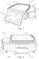
Figs. 1 and 2 are perspective views of an exemplary weighing apparatus; -
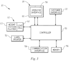
Fig. 3 is a schematic depiction of the weighing apparatus; -
Fig. 4 is a schematic view of a thermal printhead orientation along a label stock feed path; -
Figs. 5A and 5B show printed labels that depict controlled use of a marginal dot for printing only in the bar code field; and -
Figs. 6A and 6B show printed labels that depict selective shift of a bar code print field to avoid use of a marginal dot even in the bar code print field. - Referring to
Figs. 1-3 , aweighing apparatus 10 in the form of a food product scale includes aweighing station 12, which in some embodiments may be formed by aweighing platter 13 that can be removed (e.g., for cleaning) from atop thescale housing 14, and having an associated mechanism such as aload cell 62 located internal of thescale housing 14, for producing weight indicative signals when items are placed on the weighing station. An operator interface side 16 of the scale includes anoperator interface 18 configured to display information associated with scale operations. By way of example, theoperator interface 18 may be formed by a touch-screen display. Acustomer interface side 20 of the scale includes acustomer interface 22, which in certain embodiments may be formed by any suitable display screen technology. It is contemplated that thecustomer interface 22 need not include touch-screen capabilities, but it is recognized that in certain embodiments touch-screen capability could be incorporated into the customer interface as well. - A
side portion 24 of the scale housing includes alabel exit slot 26 and incorporates alabel printer 52 therein along with a label supply station. Thelabel printer 52 may employ a thermal printhead with resistive heating elements. Aremovable side panel 28 is provided to access the label supply station for replacement of the labels and to access the label printer and the label path for maintenance etc. Alternatively,member 28 may take the form of a removable cassette. -
Fig. 3 shows a high-level schematic depiction of thescale 10, including acontroller 50 interconnected with each of theoperator interface 18,customer interface 22,weighing station 12,label printer 52 and acommunications interface 54, and having associatedmemory 56. Thecontroller 50 may, for example, be any suitable processor-based controller, including one or more processors, such as a dual-core processor, with associated hardware, software and firmware to achieve desired functionality. As used herein, the term "controller" is intended to broadly encompass the collection of circuits, processors, software, firmware and/or other components that carry out the various operating and processing functions of the scale and its component parts as described herein. - The
operator interface 18 may include both adisplay device 58 and touch-screen panel 60 as shown. Theweight station platter 13 is operatively connected to aload cell 62, which produces weight indicative signals. Thecommunication interface 54 may be any suitable type (e.g., as a hardware link, such as a standard network connector, or may be formed by a wireless device such as an RF or infrared transceiver), and it is recognized that multiple communications interfaces may be provided.Memory 56 may, by way of example, take the form of one or more of non-volatile flash memory and/or random access memory, or disk on module or micro-SD. In a typical item weighing operation, an item is placed on theweigh platter 13, the operator identifies the item to the weighing apparatus (e.g., by inputting an item code via the operator interface 18) and thescale controller 50 determines the item weight (e.g., by load cell signal), prices the item (e.g., applying a price per unit weight tied to the item codes) and prints and outputs a pricing label for the item (e.g., with item name, weight, price, ingredients, allergen information, scannable bar code etc.). -
Fig. 4 shows a schematic depiction of a thermal printhead 52a employed in theweighing apparatus 10. The printhead 52a is positioned along a labelstock feed path 70 and includes a linear arrangement of thermal elements ordots 52b arranged generally perpendicular to thefeed direction 72 of thelabel stock 74. The thermal elements ordots 52b may be arranged sufficiently close to each other, across the width of the label stock, such that if adjacent thermal elements are energized at the same time, the appearance on the printed label is that of a consistent marking (e.g., without any substantial gap between adjacent dot marks formed on the label). - The
scale controller 50 is configured to measure the resistance of theprinthead heating elements 52b to determine when a given element is marginally performing and/or when a heating element has failed. In one example, this is achieved as described inU.S. Patent No. 6,846,055 , which is incorporated herein by reference, by a) periodically determining a current value proportional to the resistance of each element within the thermal printhead and b) providing a warning signal when the current value proportional to the resistance of at least one element exceeds a predetermined multiplier of a nominal value of the resistance of the element. -
Figs. 5A and 5B show implementation of the above mentioned code checker technology. InFig. 5A , a given dot that will print along thelinear zone 80 of alabel 82, and the dot, being identified as having an acceptable resistance, is turned on in all fields. InFig. 5B , the dot is turned on the bar code field (a necessary field) but is turned off in other fields 86 (ingredient field) and 88 (pricing field), resulting inslight gaps fields -
Figs. 6A and 6B show implementation of a further enhancement involving shifting of thebar code field 100 of alabel 102 being printed. As shown, the typicalbar code field 100 is made up of a series of parallel lines of varying thickness, with gaps between the lines. Thefeed direction 104 of thelabel 102 past the printhead during printing is also shown. In certain cases, if a marginal dot is positioned such that the dot will print in alinear zone 106 that requires printing of a bar code line (perFig. 6A ), the controller is configured to adjust the print operation by shifting thebar code field 100 position on thelabel 102 slightly left or right (perFig. 6B ) so that thelinear print zone 106 of the marginal element or dot either (i) aligns with a gap in thebar code field 102 or (ii) is outside the bar code field. In this way, use of an identified marginal dot for printing even the bar code field can be avoided, further extending printhead useful life. - Moreover, in practice, a printhead with even a failed element or elements (e.g., no current flow through the element(s)) could still be used to print scannable bar codes, if the shifting operation is able to shift the bar code so that the failed element(s) is not/are not needed for printing the bar code. Thus, the shifting could be implemented in the case of a failed element or, in some embodiments, only in the case of a failed element, in order to assure that a scannable bar code is printed. As used herein, the term "out of specification status" for a print element is used to refer to both (i) elements identified as marginal, (ii) elements identified as failed.
- In order to achieve the selective bar code shift, the
controller 50 evaluates the target position of the required print lines of the bar code field on the label to determine whether any print line will require use of an identified marginal dot of the print head. If so, the controller determines whether the bar code field can be shifted, left or right along ashift axis 107, to align the marginal dot with a gap in the bar code field or to position the marginal dot to the left or right of the bar code field. If so, the controller shifts the target position ai which the bar code field will be printed on the label prior to carrying out the bar code print. In the example ofFigs. 6A and 6B , the target position of thebar code field 100 is shifted in a direction toward the left side edge of the label, perarrows 108. Notably, in the example, the other print fields are not shifted. - The
controller 50 may be configured to implement certain limits to make the determination of whether the bar code field can be properly shifted. For example, a set of shift window left and right position limits 110 and 112 may be predefined such that bar code field will not be shifted outside of the left and right positions. Therefore, thecontroller 50 prevents the shift if the shift would result in movement of the bar code field beyond the set limits, in which case the marginal element or dot will be used for the bar code print. - It is to be clearly understood that the above description is intended by way of illustration and example only, is not intended to be taken by way of limitation, and that other changes and modifications are possible. For example, implementation in connection with printing devices other than printing devices in weighing scales is contemplated. Moreover, shifting of other fields to eliminate the need to print with a marginal dot or failed dot is also contemplated. In this regard, where a label or ticket to be printed is made up of multiple print fields each having a designated print position, each print field may be identified (e.g., in controller memory) according to how the print field should be handled in the case of a marginal dot or failed that is needed to produce the print field. By way of example, the table below demonstrates how a controller can be configured to determine how to deal with each print field:
Table 1 - Print Field Handling for Marginal Dot(s) and/or Failed Dot(s) Always Use Marginal Dot for Print if Needed Shift Field to Avoid Use of Marginal Dot if Possible Never Use Marginal Dot for Print PF #1 X - - PF #2 - X - PF #3 - X - PF #4 - - X PF #5 - - X - Still other variations are possible.
- Certain embodiments of the invention are described in the following numbered clauses:
- Clause 1. A printing device, comprising:
- a thermal printhead with a plurality of print elements;
- a controller configured to identify an out of specification status of at least one print element, wherein the controller is further configured to determine whether printing of a specific print field requires use of the print element having the out of specification status and, if so, to determine whether a print location of the specific print field can be shifted such that the print element having out of specification status will be one of (i) aligned with a gap in the specific print field or (ii) offset to one side of the specific print field.
- Clause 2. The printing device of clause 1, wherein the controller is configured such that, if the controller determines that the print location of the specific print field can be shifted such that the print element having out of specification status will be one of (i) aligned with a gap in the specific print field or (ii) offset to one side of the specific print field, then the controller implements a corresponding shift of the print location for purpose of a printing operation.
- Clause 3. The printing device of clause 1, wherein the controller is configured such that an amount by which the print location of the specific print field can be shifted is restricted by predefined limits.
- Clause 4. The print device of clause 1, wherein the controller is configured with memory that identifies operational instructions for multiple print fields in the case of print elements that have out of specification status.
- Clause 5. The printing device of clause 1, wherein the controller is configured to evaluate current flow through the print elements in order to identify the out of specification status.
- Clause 6. The printing device of clause 1, wherein the out of specification status is a marginal status indicative of limited useful life of the print element.
- Clause 7. The printing device of clause 1, wherein the out of specification status is a failed status.
- Clause 8. The printing device of clause 7, wherein the specific print field is a bar code field with multiple parallel lines, wherein the corresponding shift of the print location for purpose of the printing operation is implemented such that the print location is aligned with a gap between the parallel lines.
- Clause 9. A weighing scale incorporating the printing device of clause 8, further comprising:
- a weigh platter upon which items to be weighed are placed for weighing;
- wherein the controller is further configured to determine item weight, calculate an item priced from the item weight and to define lineage of the bar code print field.
-
Clause 10. A method of controlling a print operation of a printing device includes a thermal printhead with a plurality of print elements, the method comprising:- identifying an out of specification status of at least one print element;
- determining whether printing of a specific print field requires use of the print element having the out of specification status and, if so, determining whether a print location of the specific print field can be shifted such that the print element having out of specification status will be one of (i) aligned with a gap in the specific print field or (ii) offset to one side of the specific print field.
- Clause 11. The method of
clause 10, further comprising:
if a determination is made that the print location of the specific print field can be shifted such that the print element having out of specification status will be one of (i) aligned with a gap in the specific print field or (ii) offset to one side of the specific print field, then implementing a corresponding shift of the print location for purpose of a printing operation. -
Clause 12. The method ofclause 10, wherein the out of specification status is a marginal status indicative of limited useful life of the print element. -
Clause 13. The method ofclause 10, wherein the out of specification status is a failed status of the print element. -
Clause 14. The method ofclause 10, wherein the specific print field is a bar code field with multipole parallel lines, wherein the corresponding shift of the print location for purpose of a printing operation is implemented such that the print location is aligned with a gap between the parallel lines. - Clause 15. The method of
clause 10, wherein the printing device is incorporated into a weighing scaled that determines and item weight, calculates an item price from the item weight and defines lineage of the bar code print field. - Clause 16. A printing device, comprising:
- a thermal printhead with a plurality of print elements;
- a controller configured to identify a marginal status of at least one print element,
- wherein the controller is further configured to determine whether printing of a bar code print field made up of multiple parallel lines requires use of the print element having the marginal status and, if so, to shift a print location of the bar code print field on the label such that the print element having the marginal status will be one of (i) aligned with a gap between the parallel lines of the bar code print field or (ii) offset to one side of the bar code print field.
- Clause 17. The printing device of clause 16, wherein the controller is configured to shift the print location of the bar code print field along an axis that runs perpendicular to parallel lines of the bar code print field.
-
Clause 18. The printing device of clause 17, wherein the controller is configured such that an amount by which the print location of the bar code print field can be shifted is restricted by predefined limits. - Clause 19. The printing device of clause 16, wherein the controller is configured to evaluate current flow through the print elements in order to identify the marginal status.
-
Clause 20. A weighing scale incorporating the printing device of clause 15, further comprising:- a weigh platter upon which items to be weighed are placed for weighing.
- wherein the controller is further configured to determine item weight, calculate an item priced from the item weight and to define lineage of the bar code print field.
Claims (15)
- A printing device, comprising:a thermal printhead with a plurality of print elements;a controller configured to identify an out of specification status of at least one print element, wherein the controller is further configured to determine whether printing of a specific print field requires use of the print element having the out of specification status and, if so, to determine whether a print location of the specific print field can be shifted such that the print element having out of specification status will be one of (i) aligned with a gap in the specific print field or (ii) offset to one side of the specific print field.
- The printing device of claim 1, wherein the controller is configured such that, if the controller determines that the print location of the specific print field can be shifted such that the print element having out of specification status will be one of (i) aligned with a gap in the specific print field or (ii) offset to one side of the specific print field, then the controller implements a corresponding shift of the print location for purpose of a printing operation.
- The printing device of claim 1, wherein the controller is configured such that an amount by which the print location of the specific print field can be shifted is restricted by predefined limits.
- The print device of claim 1, wherein the controller is configured with memory that identifies operational instructions for multiple print fields in the case of print elements that have out of specification status.
- The printing device of claim 1, wherein the controller is configured to evaluate current flow through the print elements in order to identify the out of specification status.
- The printing device of claim 1, wherein the out of specification status is a marginal status indicative of limited useful life of the print element.
- The printing device of claim 1, wherein the out of specification status is a failed status.
- The printing device of claim 7, wherein the specific print field is a bar code field with multiple parallel lines, wherein the corresponding shift of the print location for purpose of the printing operation is implemented such that the print location is aligned with a gap between the parallel lines.
- A weighing scale incorporating the printing device of claim 8, further comprising:a weigh platter upon which items to be weighed are placed for weighing;wherein the controller is further configured to determine item weight, calculate an item priced from the item weight and to define lineage of the bar code print field.
- A method of controlling a print operation of a printing device includes a thermal printhead with a plurality of print elements, the method comprising:identifying an out of specification status of at least one print element;determining whether printing of a specific print field requires use of the print element having the out of specification status and, if so, determining whether a print location of the specific print field can be shifted such that the print element having out of specification status will be one of (i) aligned with a gap in the specific print field or (ii) offset to one side of the specific print field.
- The method of claim 10, further comprising:
if a determination is made that the print location of the specific print field can be shifted such that the print element having out of specification status will be one of (i) aligned with a gap in the specific print field or (ii) offset to one side of the specific print field, then implementing a corresponding shift of the print location for purpose of a printing operation. - The method of claim 10, wherein the out of specification status is a marginal status indicative of limited useful life of the print element.
- The method of claim 10, wherein the out of specification status is a failed status of the print element.
- The method of claim 10, wherein the specific print field is a bar code field with multipole parallel lines, wherein the corresponding shift of the print location for purpose of a printing operation is implemented such that the print location is aligned with a gap between the parallel lines.
- The method of claim 10, wherein the printing device is incorporated into a weighing scaled that determines and item weight, calculates an item price from the item weight and defines lineage of the bar code print field.
Applications Claiming Priority (2)
| Application Number | Priority Date | Filing Date | Title |
|---|---|---|---|
| US202063061271P | 2020-08-05 | 2020-08-05 | |
| US17/380,558 US11623456B2 (en) | 2020-08-05 | 2021-07-20 | Label printer with barcode shifting and scale incorporating such a label printer |
Publications (2)
| Publication Number | Publication Date |
|---|---|
| EP3950360A1 true EP3950360A1 (en) | 2022-02-09 |
| EP3950360B1 EP3950360B1 (en) | 2024-06-12 |
Family
ID=77155698
Family Applications (1)
| Application Number | Title | Priority Date | Filing Date |
|---|---|---|---|
| EP21188840.9A Active EP3950360B1 (en) | 2020-08-05 | 2021-07-30 | Label printer with barcode shifting and scale incorporating such a label printer |
Country Status (2)
| Country | Link |
|---|---|
| US (1) | US11623456B2 (en) |
| EP (1) | EP3950360B1 (en) |
Citations (1)
| Publication number | Priority date | Publication date | Assignee | Title |
|---|---|---|---|---|
| US6846055B2 (en) | 2000-02-08 | 2005-01-25 | Avery Berkel Limited | Thermal printhead operation |
Family Cites Families (6)
| Publication number | Priority date | Publication date | Assignee | Title |
|---|---|---|---|---|
| JPS5831777A (en) | 1981-08-19 | 1983-02-24 | Ishida Scales Mfg Co Ltd | Avoiding of faulty element for thermal printer |
| CA2242500C (en) | 1997-09-15 | 2007-11-13 | Monarch Marking Systems, Inc. | Early thermal printhead failure prediction system |
| JP2001270143A (en) * | 2000-03-24 | 2001-10-02 | Toshiba Tec Corp | Line printer |
| JP2009067012A (en) * | 2007-09-18 | 2009-04-02 | Oki Electric Ind Co Ltd | Printer |
| JP5720098B2 (en) | 2010-01-22 | 2015-05-20 | セイコーエプソン株式会社 | Head element operation confirmation mechanism and head element operation confirmation method |
| JP2019084799A (en) | 2017-11-10 | 2019-06-06 | セイコーエプソン株式会社 | Thermal printer, control method of thermal printer, and printing system |
-
2021
- 2021-07-20 US US17/380,558 patent/US11623456B2/en active Active
- 2021-07-30 EP EP21188840.9A patent/EP3950360B1/en active Active
Patent Citations (1)
| Publication number | Priority date | Publication date | Assignee | Title |
|---|---|---|---|---|
| US6846055B2 (en) | 2000-02-08 | 2005-01-25 | Avery Berkel Limited | Thermal printhead operation |
Also Published As
| Publication number | Publication date |
|---|---|
| EP3950360B1 (en) | 2024-06-12 |
| US11623456B2 (en) | 2023-04-11 |
| US20220040994A1 (en) | 2022-02-10 |
Similar Documents
| Publication | Publication Date | Title |
|---|---|---|
| US4661001A (en) | Label printer with test pattern for price and bar codes | |
| US4630067A (en) | Bar code printer | |
| US4587411A (en) | Method of printing, evaluating and checking the printing image of a printer and apparatus for carrying out said process | |
| US7099038B2 (en) | Method and system for controlling messages printed by an in-store label printer and related label structure | |
| EP0362075A3 (en) | Electronic scale device with printer for retail stores | |
| US20110292435A1 (en) | Printer with in-line scanner | |
| NZ280802A (en) | Weighing scale incorporates label cassette and printer | |
| WO1999006217A1 (en) | Media control to eliminate printing images beyond the media boundaries | |
| US20100185483A1 (en) | Scale with kiosk ordering interface system and method | |
| CA2514003C (en) | Scale with automatic identification of specials and other price and product changes | |
| EP3950360B1 (en) | Label printer with barcode shifting and scale incorporating such a label printer | |
| US20040090642A1 (en) | Commodity information printing apparatus and commodity label attachment | |
| JPS644920B2 (en) | ||
| EP1703446B1 (en) | Printing apparatus | |
| US6846055B2 (en) | Thermal printhead operation | |
| US6250547B1 (en) | Cash register having sawteeth shaped circular perforator | |
| GB2077663A (en) | Printing apparatus | |
| US20260001330A1 (en) | Printer, food product scale and associated printhead assembly | |
| EP3208089A1 (en) | Embedded color bar and method | |
| US20040017578A1 (en) | Method of detecting bad dots in print zone | |
| JP2002301835A (en) | Label printer | |
| US6994265B2 (en) | ATM receipt | |
| JPS62162164A (en) | POS terminal | |
| KR20000067678A (en) | ribbon exchange time invitation method of dot printer | |
| JPH0629775B2 (en) | Label printer |
Legal Events
| Date | Code | Title | Description |
|---|---|---|---|
| PUAI | Public reference made under article 153(3) epc to a published international application that has entered the european phase |
Free format text: ORIGINAL CODE: 0009012 |
|
| STAA | Information on the status of an ep patent application or granted ep patent |
Free format text: STATUS: THE APPLICATION HAS BEEN PUBLISHED |
|
| AK | Designated contracting states |
Kind code of ref document: A1 Designated state(s): AL AT BE BG CH CY CZ DE DK EE ES FI FR GB GR HR HU IE IS IT LI LT LU LV MC MK MT NL NO PL PT RO RS SE SI SK SM TR |
|
| STAA | Information on the status of an ep patent application or granted ep patent |
Free format text: STATUS: REQUEST FOR EXAMINATION WAS MADE |
|
| 17P | Request for examination filed |
Effective date: 20220805 |
|
| RBV | Designated contracting states (corrected) |
Designated state(s): AL AT BE BG CH CY CZ DE DK EE ES FI FR GB GR HR HU IE IS IT LI LT LU LV MC MK MT NL NO PL PT RO RS SE SI SK SM TR |
|
| STAA | Information on the status of an ep patent application or granted ep patent |
Free format text: STATUS: EXAMINATION IS IN PROGRESS |
|
| 17Q | First examination report despatched |
Effective date: 20230516 |
|
| GRAP | Despatch of communication of intention to grant a patent |
Free format text: ORIGINAL CODE: EPIDOSNIGR1 |
|
| STAA | Information on the status of an ep patent application or granted ep patent |
Free format text: STATUS: GRANT OF PATENT IS INTENDED |
|
| INTG | Intention to grant announced |
Effective date: 20240207 |
|
| P01 | Opt-out of the competence of the unified patent court (upc) registered |
Effective date: 20240223 |
|
| GRAS | Grant fee paid |
Free format text: ORIGINAL CODE: EPIDOSNIGR3 |
|
| GRAA | (expected) grant |
Free format text: ORIGINAL CODE: 0009210 |
|
| STAA | Information on the status of an ep patent application or granted ep patent |
Free format text: STATUS: THE PATENT HAS BEEN GRANTED |
|
| AK | Designated contracting states |
Kind code of ref document: B1 Designated state(s): AL AT BE BG CH CY CZ DE DK EE ES FI FR GB GR HR HU IE IS IT LI LT LU LV MC MK MT NL NO PL PT RO RS SE SI SK SM TR |
|
| REG | Reference to a national code |
Ref country code: GB Ref legal event code: FG4D |
|
| REG | Reference to a national code |
Ref country code: CH Ref legal event code: EP |
|
| REG | Reference to a national code |
Ref country code: DE Ref legal event code: R096 Ref document number: 602021014259 Country of ref document: DE |
|
| REG | Reference to a national code |
Ref country code: IE Ref legal event code: FG4D |
|
| PG25 | Lapsed in a contracting state [announced via postgrant information from national office to epo] |
Ref country code: BG Free format text: LAPSE BECAUSE OF FAILURE TO SUBMIT A TRANSLATION OF THE DESCRIPTION OR TO PAY THE FEE WITHIN THE PRESCRIBED TIME-LIMIT Effective date: 20240612 |
|
| PG25 | Lapsed in a contracting state [announced via postgrant information from national office to epo] |
Ref country code: HR Free format text: LAPSE BECAUSE OF FAILURE TO SUBMIT A TRANSLATION OF THE DESCRIPTION OR TO PAY THE FEE WITHIN THE PRESCRIBED TIME-LIMIT Effective date: 20240612 Ref country code: FI Free format text: LAPSE BECAUSE OF FAILURE TO SUBMIT A TRANSLATION OF THE DESCRIPTION OR TO PAY THE FEE WITHIN THE PRESCRIBED TIME-LIMIT Effective date: 20240612 |
|
| REG | Reference to a national code |
Ref country code: LT Ref legal event code: MG9D |
|
| PG25 | Lapsed in a contracting state [announced via postgrant information from national office to epo] |
Ref country code: GR Free format text: LAPSE BECAUSE OF FAILURE TO SUBMIT A TRANSLATION OF THE DESCRIPTION OR TO PAY THE FEE WITHIN THE PRESCRIBED TIME-LIMIT Effective date: 20240913 |
|
| REG | Reference to a national code |
Ref country code: NL Ref legal event code: MP Effective date: 20240612 |
|
| PG25 | Lapsed in a contracting state [announced via postgrant information from national office to epo] |
Ref country code: ES Free format text: LAPSE BECAUSE OF FAILURE TO SUBMIT A TRANSLATION OF THE DESCRIPTION OR TO PAY THE FEE WITHIN THE PRESCRIBED TIME-LIMIT Effective date: 20240612 |
|
| PG25 | Lapsed in a contracting state [announced via postgrant information from national office to epo] |
Ref country code: LV Free format text: LAPSE BECAUSE OF FAILURE TO SUBMIT A TRANSLATION OF THE DESCRIPTION OR TO PAY THE FEE WITHIN THE PRESCRIBED TIME-LIMIT Effective date: 20240612 |
|
| PG25 | Lapsed in a contracting state [announced via postgrant information from national office to epo] |
Ref country code: NO Free format text: LAPSE BECAUSE OF FAILURE TO SUBMIT A TRANSLATION OF THE DESCRIPTION OR TO PAY THE FEE WITHIN THE PRESCRIBED TIME-LIMIT Effective date: 20240912 Ref country code: LV Free format text: LAPSE BECAUSE OF FAILURE TO SUBMIT A TRANSLATION OF THE DESCRIPTION OR TO PAY THE FEE WITHIN THE PRESCRIBED TIME-LIMIT Effective date: 20240612 Ref country code: HR Free format text: LAPSE BECAUSE OF FAILURE TO SUBMIT A TRANSLATION OF THE DESCRIPTION OR TO PAY THE FEE WITHIN THE PRESCRIBED TIME-LIMIT Effective date: 20240612 Ref country code: GR Free format text: LAPSE BECAUSE OF FAILURE TO SUBMIT A TRANSLATION OF THE DESCRIPTION OR TO PAY THE FEE WITHIN THE PRESCRIBED TIME-LIMIT Effective date: 20240913 Ref country code: FI Free format text: LAPSE BECAUSE OF FAILURE TO SUBMIT A TRANSLATION OF THE DESCRIPTION OR TO PAY THE FEE WITHIN THE PRESCRIBED TIME-LIMIT Effective date: 20240612 Ref country code: ES Free format text: LAPSE BECAUSE OF FAILURE TO SUBMIT A TRANSLATION OF THE DESCRIPTION OR TO PAY THE FEE WITHIN THE PRESCRIBED TIME-LIMIT Effective date: 20240612 Ref country code: BG Free format text: LAPSE BECAUSE OF FAILURE TO SUBMIT A TRANSLATION OF THE DESCRIPTION OR TO PAY THE FEE WITHIN THE PRESCRIBED TIME-LIMIT Effective date: 20240612 Ref country code: RS Free format text: LAPSE BECAUSE OF FAILURE TO SUBMIT A TRANSLATION OF THE DESCRIPTION OR TO PAY THE FEE WITHIN THE PRESCRIBED TIME-LIMIT Effective date: 20240912 |
|
| PG25 | Lapsed in a contracting state [announced via postgrant information from national office to epo] |
Ref country code: NL Free format text: LAPSE BECAUSE OF FAILURE TO SUBMIT A TRANSLATION OF THE DESCRIPTION OR TO PAY THE FEE WITHIN THE PRESCRIBED TIME-LIMIT Effective date: 20240612 |
|
| REG | Reference to a national code |
Ref country code: AT Ref legal event code: MK05 Ref document number: 1693910 Country of ref document: AT Kind code of ref document: T Effective date: 20240612 |
|
| PG25 | Lapsed in a contracting state [announced via postgrant information from national office to epo] |
Ref country code: NL Free format text: LAPSE BECAUSE OF FAILURE TO SUBMIT A TRANSLATION OF THE DESCRIPTION OR TO PAY THE FEE WITHIN THE PRESCRIBED TIME-LIMIT Effective date: 20240612 |
|
| PG25 | Lapsed in a contracting state [announced via postgrant information from national office to epo] |
Ref country code: PT Free format text: LAPSE BECAUSE OF FAILURE TO SUBMIT A TRANSLATION OF THE DESCRIPTION OR TO PAY THE FEE WITHIN THE PRESCRIBED TIME-LIMIT Effective date: 20241014 |
|
| PG25 | Lapsed in a contracting state [announced via postgrant information from national office to epo] |
Ref country code: PT Free format text: LAPSE BECAUSE OF FAILURE TO SUBMIT A TRANSLATION OF THE DESCRIPTION OR TO PAY THE FEE WITHIN THE PRESCRIBED TIME-LIMIT Effective date: 20241014 |
|
| PG25 | Lapsed in a contracting state [announced via postgrant information from national office to epo] |
Ref country code: PL Free format text: LAPSE BECAUSE OF FAILURE TO SUBMIT A TRANSLATION OF THE DESCRIPTION OR TO PAY THE FEE WITHIN THE PRESCRIBED TIME-LIMIT Effective date: 20240612 |
|
| PG25 | Lapsed in a contracting state [announced via postgrant information from national office to epo] |
Ref country code: EE Free format text: LAPSE BECAUSE OF FAILURE TO SUBMIT A TRANSLATION OF THE DESCRIPTION OR TO PAY THE FEE WITHIN THE PRESCRIBED TIME-LIMIT Effective date: 20240612 |
|
| PG25 | Lapsed in a contracting state [announced via postgrant information from national office to epo] |
Ref country code: AT Free format text: LAPSE BECAUSE OF FAILURE TO SUBMIT A TRANSLATION OF THE DESCRIPTION OR TO PAY THE FEE WITHIN THE PRESCRIBED TIME-LIMIT Effective date: 20240612 Ref country code: IS Free format text: LAPSE BECAUSE OF FAILURE TO SUBMIT A TRANSLATION OF THE DESCRIPTION OR TO PAY THE FEE WITHIN THE PRESCRIBED TIME-LIMIT Effective date: 20241012 |
|
| PG25 | Lapsed in a contracting state [announced via postgrant information from national office to epo] |
Ref country code: CZ Free format text: LAPSE BECAUSE OF FAILURE TO SUBMIT A TRANSLATION OF THE DESCRIPTION OR TO PAY THE FEE WITHIN THE PRESCRIBED TIME-LIMIT Effective date: 20240612 |
|
| PG25 | Lapsed in a contracting state [announced via postgrant information from national office to epo] |
Ref country code: RO Free format text: LAPSE BECAUSE OF FAILURE TO SUBMIT A TRANSLATION OF THE DESCRIPTION OR TO PAY THE FEE WITHIN THE PRESCRIBED TIME-LIMIT Effective date: 20240612 Ref country code: SK Free format text: LAPSE BECAUSE OF FAILURE TO SUBMIT A TRANSLATION OF THE DESCRIPTION OR TO PAY THE FEE WITHIN THE PRESCRIBED TIME-LIMIT Effective date: 20240612 |
|
| PG25 | Lapsed in a contracting state [announced via postgrant information from national office to epo] |
Ref country code: SM Free format text: LAPSE BECAUSE OF FAILURE TO SUBMIT A TRANSLATION OF THE DESCRIPTION OR TO PAY THE FEE WITHIN THE PRESCRIBED TIME-LIMIT Effective date: 20240612 |
|
| PG25 | Lapsed in a contracting state [announced via postgrant information from national office to epo] |
Ref country code: SM Free format text: LAPSE BECAUSE OF FAILURE TO SUBMIT A TRANSLATION OF THE DESCRIPTION OR TO PAY THE FEE WITHIN THE PRESCRIBED TIME-LIMIT Effective date: 20240612 Ref country code: SK Free format text: LAPSE BECAUSE OF FAILURE TO SUBMIT A TRANSLATION OF THE DESCRIPTION OR TO PAY THE FEE WITHIN THE PRESCRIBED TIME-LIMIT Effective date: 20240612 Ref country code: RO Free format text: LAPSE BECAUSE OF FAILURE TO SUBMIT A TRANSLATION OF THE DESCRIPTION OR TO PAY THE FEE WITHIN THE PRESCRIBED TIME-LIMIT Effective date: 20240612 Ref country code: PL Free format text: LAPSE BECAUSE OF FAILURE TO SUBMIT A TRANSLATION OF THE DESCRIPTION OR TO PAY THE FEE WITHIN THE PRESCRIBED TIME-LIMIT Effective date: 20240612 Ref country code: IS Free format text: LAPSE BECAUSE OF FAILURE TO SUBMIT A TRANSLATION OF THE DESCRIPTION OR TO PAY THE FEE WITHIN THE PRESCRIBED TIME-LIMIT Effective date: 20241012 Ref country code: EE Free format text: LAPSE BECAUSE OF FAILURE TO SUBMIT A TRANSLATION OF THE DESCRIPTION OR TO PAY THE FEE WITHIN THE PRESCRIBED TIME-LIMIT Effective date: 20240612 Ref country code: CZ Free format text: LAPSE BECAUSE OF FAILURE TO SUBMIT A TRANSLATION OF THE DESCRIPTION OR TO PAY THE FEE WITHIN THE PRESCRIBED TIME-LIMIT Effective date: 20240612 Ref country code: AT Free format text: LAPSE BECAUSE OF FAILURE TO SUBMIT A TRANSLATION OF THE DESCRIPTION OR TO PAY THE FEE WITHIN THE PRESCRIBED TIME-LIMIT Effective date: 20240612 |
|
| REG | Reference to a national code |
Ref country code: CH Ref legal event code: PL |
|
| REG | Reference to a national code |
Ref country code: DE Ref legal event code: R097 Ref document number: 602021014259 Country of ref document: DE |
|
| PG25 | Lapsed in a contracting state [announced via postgrant information from national office to epo] |
Ref country code: LU Free format text: LAPSE BECAUSE OF NON-PAYMENT OF DUE FEES Effective date: 20240730 |
|
| PG25 | Lapsed in a contracting state [announced via postgrant information from national office to epo] |
Ref country code: MC Free format text: LAPSE BECAUSE OF FAILURE TO SUBMIT A TRANSLATION OF THE DESCRIPTION OR TO PAY THE FEE WITHIN THE PRESCRIBED TIME-LIMIT Effective date: 20240612 |
|
| PG25 | Lapsed in a contracting state [announced via postgrant information from national office to epo] |
Ref country code: MC Free format text: LAPSE BECAUSE OF FAILURE TO SUBMIT A TRANSLATION OF THE DESCRIPTION OR TO PAY THE FEE WITHIN THE PRESCRIBED TIME-LIMIT Effective date: 20240612 Ref country code: LU Free format text: LAPSE BECAUSE OF NON-PAYMENT OF DUE FEES Effective date: 20240730 |
|
| PG25 | Lapsed in a contracting state [announced via postgrant information from national office to epo] |
Ref country code: DK Free format text: LAPSE BECAUSE OF FAILURE TO SUBMIT A TRANSLATION OF THE DESCRIPTION OR TO PAY THE FEE WITHIN THE PRESCRIBED TIME-LIMIT Effective date: 20240612 |
|
| PLBE | No opposition filed within time limit |
Free format text: ORIGINAL CODE: 0009261 |
|
| STAA | Information on the status of an ep patent application or granted ep patent |
Free format text: STATUS: NO OPPOSITION FILED WITHIN TIME LIMIT |
|
| PG25 | Lapsed in a contracting state [announced via postgrant information from national office to epo] |
Ref country code: BE Free format text: LAPSE BECAUSE OF NON-PAYMENT OF DUE FEES Effective date: 20240731 Ref country code: CH Free format text: LAPSE BECAUSE OF NON-PAYMENT OF DUE FEES Effective date: 20240731 |
|
| 26N | No opposition filed |
Effective date: 20250313 |
|
| REG | Reference to a national code |
Ref country code: BE Ref legal event code: MM Effective date: 20240731 |
|
| PG25 | Lapsed in a contracting state [announced via postgrant information from national office to epo] |
Ref country code: IE Free format text: LAPSE BECAUSE OF NON-PAYMENT OF DUE FEES Effective date: 20240730 |
|
| PG25 | Lapsed in a contracting state [announced via postgrant information from national office to epo] |
Ref country code: SE Free format text: LAPSE BECAUSE OF FAILURE TO SUBMIT A TRANSLATION OF THE DESCRIPTION OR TO PAY THE FEE WITHIN THE PRESCRIBED TIME-LIMIT Effective date: 20240612 |
|
| PGFP | Annual fee paid to national office [announced via postgrant information from national office to epo] |
Ref country code: DE Payment date: 20250729 Year of fee payment: 5 |
|
| PGFP | Annual fee paid to national office [announced via postgrant information from national office to epo] |
Ref country code: IT Payment date: 20250721 Year of fee payment: 5 |
|
| PGFP | Annual fee paid to national office [announced via postgrant information from national office to epo] |
Ref country code: GB Payment date: 20250728 Year of fee payment: 5 |
|
| PGFP | Annual fee paid to national office [announced via postgrant information from national office to epo] |
Ref country code: FR Payment date: 20250728 Year of fee payment: 5 |
|
| PG25 | Lapsed in a contracting state [announced via postgrant information from national office to epo] |
Ref country code: CY Free format text: LAPSE BECAUSE OF FAILURE TO SUBMIT A TRANSLATION OF THE DESCRIPTION OR TO PAY THE FEE WITHIN THE PRESCRIBED TIME-LIMIT; INVALID AB INITIO Effective date: 20210730 |
|
| PG25 | Lapsed in a contracting state [announced via postgrant information from national office to epo] |
Ref country code: HU Free format text: LAPSE BECAUSE OF FAILURE TO SUBMIT A TRANSLATION OF THE DESCRIPTION OR TO PAY THE FEE WITHIN THE PRESCRIBED TIME-LIMIT; INVALID AB INITIO Effective date: 20210730 |