EP3950359A1 - Liquid ejection head and recording device - Google Patents
Liquid ejection head and recording device Download PDFInfo
- Publication number
- EP3950359A1 EP3950359A1 EP20778680.7A EP20778680A EP3950359A1 EP 3950359 A1 EP3950359 A1 EP 3950359A1 EP 20778680 A EP20778680 A EP 20778680A EP 3950359 A1 EP3950359 A1 EP 3950359A1
- Authority
- EP
- European Patent Office
- Prior art keywords
- flow channel
- reservoir
- supply
- liquid
- liquid discharge
- Prior art date
- Legal status (The legal status is an assumption and is not a legal conclusion. Google has not performed a legal analysis and makes no representation as to the accuracy of the status listed.)
- Granted
Links
Images






Classifications
-
- B—PERFORMING OPERATIONS; TRANSPORTING
- B41—PRINTING; LINING MACHINES; TYPEWRITERS; STAMPS
- B41J—TYPEWRITERS; SELECTIVE PRINTING MECHANISMS, i.e. MECHANISMS PRINTING OTHERWISE THAN FROM A FORME; CORRECTION OF TYPOGRAPHICAL ERRORS
- B41J2/00—Typewriters or selective printing mechanisms characterised by the printing or marking process for which they are designed
- B41J2/005—Typewriters or selective printing mechanisms characterised by the printing or marking process for which they are designed characterised by bringing liquid or particles selectively into contact with a printing material
- B41J2/01—Ink jet
- B41J2/135—Nozzles
- B41J2/14—Structure thereof only for on-demand ink jet heads
- B41J2/14201—Structure of print heads with piezoelectric elements
- B41J2/14209—Structure of print heads with piezoelectric elements of finger type, chamber walls consisting integrally of piezoelectric material
-
- B—PERFORMING OPERATIONS; TRANSPORTING
- B41—PRINTING; LINING MACHINES; TYPEWRITERS; STAMPS
- B41J—TYPEWRITERS; SELECTIVE PRINTING MECHANISMS, i.e. MECHANISMS PRINTING OTHERWISE THAN FROM A FORME; CORRECTION OF TYPOGRAPHICAL ERRORS
- B41J2/00—Typewriters or selective printing mechanisms characterised by the printing or marking process for which they are designed
- B41J2/005—Typewriters or selective printing mechanisms characterised by the printing or marking process for which they are designed characterised by bringing liquid or particles selectively into contact with a printing material
- B41J2/01—Ink jet
- B41J2/17—Ink jet characterised by ink handling
- B41J2/175—Ink supply systems ; Circuit parts therefor
- B41J2/17503—Ink cartridges
- B41J2/1752—Mounting within the printer
- B41J2/17523—Ink connection
-
- B—PERFORMING OPERATIONS; TRANSPORTING
- B41—PRINTING; LINING MACHINES; TYPEWRITERS; STAMPS
- B41J—TYPEWRITERS; SELECTIVE PRINTING MECHANISMS, i.e. MECHANISMS PRINTING OTHERWISE THAN FROM A FORME; CORRECTION OF TYPOGRAPHICAL ERRORS
- B41J2/00—Typewriters or selective printing mechanisms characterised by the printing or marking process for which they are designed
- B41J2/005—Typewriters or selective printing mechanisms characterised by the printing or marking process for which they are designed characterised by bringing liquid or particles selectively into contact with a printing material
- B41J2/01—Ink jet
- B41J2/17—Ink jet characterised by ink handling
- B41J2/175—Ink supply systems ; Circuit parts therefor
- B41J2/17563—Ink filters
-
- B—PERFORMING OPERATIONS; TRANSPORTING
- B41—PRINTING; LINING MACHINES; TYPEWRITERS; STAMPS
- B41J—TYPEWRITERS; SELECTIVE PRINTING MECHANISMS, i.e. MECHANISMS PRINTING OTHERWISE THAN FROM A FORME; CORRECTION OF TYPOGRAPHICAL ERRORS
- B41J2/00—Typewriters or selective printing mechanisms characterised by the printing or marking process for which they are designed
- B41J2/005—Typewriters or selective printing mechanisms characterised by the printing or marking process for which they are designed characterised by bringing liquid or particles selectively into contact with a printing material
- B41J2/01—Ink jet
- B41J2/17—Ink jet characterised by ink handling
- B41J2/19—Ink jet characterised by ink handling for removing air bubbles
-
- B—PERFORMING OPERATIONS; TRANSPORTING
- B41—PRINTING; LINING MACHINES; TYPEWRITERS; STAMPS
- B41J—TYPEWRITERS; SELECTIVE PRINTING MECHANISMS, i.e. MECHANISMS PRINTING OTHERWISE THAN FROM A FORME; CORRECTION OF TYPOGRAPHICAL ERRORS
- B41J2/00—Typewriters or selective printing mechanisms characterised by the printing or marking process for which they are designed
- B41J2/005—Typewriters or selective printing mechanisms characterised by the printing or marking process for which they are designed characterised by bringing liquid or particles selectively into contact with a printing material
- B41J2/01—Ink jet
- B41J2/135—Nozzles
- B41J2/14—Structure thereof only for on-demand ink jet heads
- B41J2/14201—Structure of print heads with piezoelectric elements
- B41J2/14209—Structure of print heads with piezoelectric elements of finger type, chamber walls consisting integrally of piezoelectric material
- B41J2002/14225—Finger type piezoelectric element on only one side of the chamber
-
- B—PERFORMING OPERATIONS; TRANSPORTING
- B41—PRINTING; LINING MACHINES; TYPEWRITERS; STAMPS
- B41J—TYPEWRITERS; SELECTIVE PRINTING MECHANISMS, i.e. MECHANISMS PRINTING OTHERWISE THAN FROM A FORME; CORRECTION OF TYPOGRAPHICAL ERRORS
- B41J2/00—Typewriters or selective printing mechanisms characterised by the printing or marking process for which they are designed
- B41J2/005—Typewriters or selective printing mechanisms characterised by the printing or marking process for which they are designed characterised by bringing liquid or particles selectively into contact with a printing material
- B41J2/01—Ink jet
- B41J2/135—Nozzles
- B41J2/14—Structure thereof only for on-demand ink jet heads
- B41J2/14201—Structure of print heads with piezoelectric elements
- B41J2002/14306—Flow passage between manifold and chamber
-
- B—PERFORMING OPERATIONS; TRANSPORTING
- B41—PRINTING; LINING MACHINES; TYPEWRITERS; STAMPS
- B41J—TYPEWRITERS; SELECTIVE PRINTING MECHANISMS, i.e. MECHANISMS PRINTING OTHERWISE THAN FROM A FORME; CORRECTION OF TYPOGRAPHICAL ERRORS
- B41J2/00—Typewriters or selective printing mechanisms characterised by the printing or marking process for which they are designed
- B41J2/005—Typewriters or selective printing mechanisms characterised by the printing or marking process for which they are designed characterised by bringing liquid or particles selectively into contact with a printing material
- B41J2/01—Ink jet
- B41J2/135—Nozzles
- B41J2/14—Structure thereof only for on-demand ink jet heads
- B41J2002/14419—Manifold
-
- B—PERFORMING OPERATIONS; TRANSPORTING
- B41—PRINTING; LINING MACHINES; TYPEWRITERS; STAMPS
- B41J—TYPEWRITERS; SELECTIVE PRINTING MECHANISMS, i.e. MECHANISMS PRINTING OTHERWISE THAN FROM A FORME; CORRECTION OF TYPOGRAPHICAL ERRORS
- B41J2/00—Typewriters or selective printing mechanisms characterised by the printing or marking process for which they are designed
- B41J2/005—Typewriters or selective printing mechanisms characterised by the printing or marking process for which they are designed characterised by bringing liquid or particles selectively into contact with a printing material
- B41J2/01—Ink jet
- B41J2/135—Nozzles
- B41J2/14—Structure thereof only for on-demand ink jet heads
- B41J2002/14459—Matrix arrangement of the pressure chambers
Definitions
- the disclosed embodiments relate to a liquid discharge head and a recording apparatus.
- Known printing apparatuses include inkjet printers and inkjet plotters that utilize an inkjet recording method.
- An inkjet printing apparatus is installed with a liquid discharge head for discharging a liquid.
- the liquid discharge head includes a flow channel member having a plurality of discharge holes, and a supply member connected to the flow channel member.
- the supply member includes a supply flow channel and a reservoir that stores liquid from the supply flow channel, and has a flow channel configuration for supplying the liquid to the reservoir from a direction intersecting with a direction in which gravity acts (see, for example, Patent Literature 1).
- Patent Literature 1 Japanese Patent No. 4432925
- the bubbles may remain in the supply flow channel due to a difference in the direction of buoyancy acting on the bubbles and the direction in which the liquid is supplied to the reservoir.
- the bubbles remaining in the supply flow channel may hinder the flow of liquid, resulting in insufficient supply of liquid to the reservoir.
- An aspect of an embodiment of the present invention has been made in view of the above, and an object of the present invention is to provide a liquid discharge head and a recording apparatus capable of preventing insufficient supply of liquid to a reservoir.
- a liquid discharge head includes: a flow channel member including a first surface and a second surface located opposite to the first surface; a pressing unit located on the first surface; and a supply member connected to the flow channel member.
- the flow channel member includes a plurality of discharge holes located in the second surface.
- the supply member includes, in this order from an upstream side, a first supply flow channel; a first connection flow channel connected to the first supply flow channel; and a reservoir connected to the first connection flow channel.
- the first connection flow channel is connected to the second surface side of the reservoir.
- a recording apparatus includes: a flow channel member including a first surface and a second surface located opposite to the first surface; a pressing unit located on the first surface; and a supply member connected to the flow channel member.
- the flow channel member includes a plurality of discharge holes located in the second surface.
- the supply member includes, in this order from an upstream side, a first supply flow channel; a first connection flow channel connected to the first supply flow channel; and a reservoir connected to the first connection flow channel.
- the first connection flow channel includes: a liquid discharge head connected to the second surface side of the reservoir; a conveying unit configured to convey a recording medium to the liquid discharge head; and a control unit configured to control the liquid discharge head.
- insufficient supply of liquid to the reservoir can be prevented.
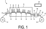
- FIGS. 1 and 2 are explanatory views of the printer 1 according to the embodiment. Specifically, FIG. 1 is a schematic side view of the printer 1 and FIG. 2 is a schematic plan view of the printer 1.
- the printer 1 according to the embodiment is, for example, a color inkjet printer.
- the printer 1 includes a paper feed roller 2, guide rollers 3, an applicator 4, a head case 5, a plurality of conveying rollers 6, a plurality of frames 7, a plurality of liquid discharge heads 8, conveying rollers 9, a dryer 10, conveying rollers 11, a sensor unit 12, and a collection roller 13.
- the conveying rollers 6 are examples of a conveying unit.
- the printer 1 includes a control unit 14 that controls the paper feed roller 2, the guide rollers 3, the applicator 4, the head case 5, the plurality of conveying rollers 6, the plurality of frames 7, the plurality of liquid discharge heads 8, the conveying rollers 9, the dryer 10, the conveying rollers 11, the sensor unit 12, and the collection roller 13.
- the printer 1 records an image and characters on a printing sheet P by causing droplets to land on the printing sheet P.
- the printing sheet P is an example of a recording medium.
- the printing sheet P is rolled on the paper feed roller 2 prior to use. In this state, the printer 1 conveys the printing sheet P from the paper feed roller 2 to the inside of the head case 5 via the guide rollers 3 and the applicator 4.
- the applicator 4 uniformly applies a coating agent over the printing sheet P. With surface treatment thus performed on the printing sheet P, the printing quality of the printer 1 can be improved.
- the head case 5 houses the plurality of conveying rollers 6, the plurality of frames 7, and the plurality of liquid discharge heads 8.
- the inside of the head case 5 is formed with a space separated from the outside except for a part connected to the outside such as parts where the printing sheet P enters and exits.
- control unit 14 controls at least one of controllable factors of the internal space of the head case 5, such as the temperature, the humidity, and barometric pressure.
- the conveying rollers 6 convey the printing sheet P to the vicinity of the liquid discharge heads 8, inside the head case 5.
- the frame 7 is a rectangular flat plate, and is positioned above and close to the printing sheet P conveyed by the conveying rollers 6. As illustrated in FIG. 2 , the frames 7 are positioned such that the longitudinal direction of the frames 7 is orthogonal to the conveyance direction of the printing sheet P. Furthermore, the plurality of (e.g., four) frames 7 are located inside the head case 5 along the conveyance direction of the printing sheet P.
- Liquid which is ink for example, is supplied to the liquid discharge heads 8 from a liquid tank (not illustrated).
- the liquid discharge heads 8 discharge the liquid supplied from the liquid tank.
- the control unit 14 controls the liquid discharge heads 8 based on data of an image, characters, and the like to discharge the liquid toward the printing sheet P.
- the distance between each liquid discharge head 8 and the printing sheet P is, for example, approximately 0.5 mm to 20 mm.
- the liquid discharge heads 8 are fixed to the frame 7.
- the liquid discharge heads 8 are positioned such that the longitudinal direction of the liquid discharge heads 8 is orthogonal to the conveyance direction of the printing sheet P.
- the printer 1 according to the embodiment is what is known as a line printer with the liquid discharge heads 8 fixed inside the printer 1.
- the printer 1 according to the embodiment is not limited to a line printer and may also be what is known as a serial printer.
- the serial printer is a printer employing a method of alternately performing operations of recording while moving the liquid discharge heads 8 in a manner such as reciprocation in a direction intersecting (e.g., substantially orthogonal to) the conveyance direction of the printing sheet P, and conveying the printing sheet P.
- FIG. 2 illustrates an example in which three liquid discharge heads 8 are located on the forward side and two liquid discharge heads 8 are located on the rear side, in the conveyance direction of the printing sheet P. Further, the liquid discharge heads 8 are positioned without their centers overlapping in the conveyance direction of the printing sheet.
- the plurality of liquid discharge heads 8 positioned in one frame 7 form a head group 8A.
- Four head groups 8A are positioned along the conveyance direction of the printing sheet P.
- the liquid discharge heads 8 belonging to the same head group 8A are supplied with ink of the same color.
- the printer 1 can perform printing with four colors of ink using the four head groups 8A.
- the colors of the ink discharged from the respective head groups 8A are, for example, magenta (M), yellow (Y), cyan (C), and black (K).
- the control unit 14 can print a color image on the printing sheet P by controlling each of the head groups 8A to discharge the plurality of colors of ink onto the printing sheet P.
- a surface treatment may be performed on the printing sheet P, by discharging a coating agent from the liquid discharge head 8 onto the printing sheet P.
- the number of the liquid discharge heads 8 included in one head group 8A and the number of the head groups 8A provided in the printer 1 can be changed as appropriate in accordance with printing targets and printing conditions. For example, if the color to be printed on the printing sheet P is a single color and the range of the printing can be covered by a single liquid discharge head 8, only a single liquid discharge head 8 may be provided in the printer 1.
- the printing sheet P thus subjected to the printing process inside the head case 5 is conveyed by the conveying rollers 9 to the outside of the head case 5, and passes through the inside of the dryer 10.
- the dryer 10 dries the printing sheet P after the printing process.
- the printing sheet P thus dried by the dryer 10 is conveyed by the conveying rollers 11 and then collected by the collection roller 13.
- the printer 1 by drying the printing sheet P with the dryer 10, it is possible to suppress bonding between the printing sheets P rolled while being overlapped with each other, and rubbing between undried liquid at the collection roller 13.
- the sensor unit 12 includes a position sensor, a speed sensor, a temperature sensor, and the like. Based on information from the sensor unit 12, the control unit 14 can determine the state of each part of the printer 1 and control each part of the printer 1.
- the printing sheet P is the printing target (i.e., the recording medium), but the printing target in the printer 1 is not limited to the printing sheet P, and a roll type fabric or the like may be the printing target.
- the printer 1 may be mounted on a conveyor belt and then conveyed. If a conveyor belt is used, the printing target of the printer 1 can be flat paper, cut cloth, wood, tile, or the like.
- the printer 1 may discharge a liquid containing electrically conductive particles from the liquid discharge head 8, to print a wiring pattern or the like of an electronic device. Furthermore, the printer 1 may discharge liquid containing a predetermined amount of liquid chemical agent or liquid containing the chemical agent from the liquid discharge head 8 onto a reaction vessel or the like to produce chemicals.
- the printer 1 may also include a cleaning unit for cleaning the liquid discharge heads 8.
- the cleaning unit cleans the liquid discharge heads 8 by, for example, a wiping process or a capping process.
- the wiping process is, for example, a process of removing liquid attached to a second surface 24b (see FIG. 3 ) of a flow channel member 24 (see FIG. 3 ), which is an example of a surface of a portion onto which the liquid is discharged, by rubbing the second surface 24b with a flexible wiper.
- the capping process is performed as follows, for example. First of all, a cap is provided to cover the second surface 24b of the flow channel member 24 which is an example of the portion onto which the liquid is discharged (this action is referred to as capping). As a result, a substantially sealed space is formed between the second surface 24b and the cap.
- FIG. 3 is an exploded perspective view illustrating a schematic configuration of the liquid discharge head 8 according to the embodiment.
- the liquid discharge head 8 includes a head main body 20, a supply member 21, a circuit substrate 22, and a head cover 23.
- the head main body 20 includes the flow channel member 24, a piezoelectric actuator substrate 25, a signal transmission unit 26, and a drive IC 27.
- the flow channel member 24 of the head main body 20 has a substantially flat plate shape and includes a first surface 24a, which is one main surface, and the second surface 24b located on a side opposite to the first surface 24a.
- the first surface 24a has an opening 241a (see FIG. 4 ), and a liquid is supplied into the flow channel member 24 from the supply member 21 described later through the opening 241a.
- a plurality of the discharge holes 243 that discharge liquid onto the printing sheet P are located on the second surface 24b. Furthermore, a flow channel through which liquid flows from the first surface 24a to the second surface 24b is located inside the flow channel member 24.
- the piezoelectric actuator substrate 25 is located on the first surface 24a of the flow channel member 24.
- the piezoelectric actuator substrate 25 includes a plurality of the displaced elements 30 (see FIG. 6 ).
- the displaced elements 30 are examples of a pressing unit.
- the displaced elements 30 are located on the first surface 24a of the flow channel member 24.
- the piezoelectric actuator substrate 25 will be described later with reference to FIG. 6 .
- Each signal transmission unit 26 is electrically connected to the piezoelectric actuator substrate 25.
- Each signal transmission unit 26 includes a plurality of the drive integrated circuits (ICs) 27. Note that, in FIG. 3 , one of the signal transmission units 26 is omitted for ease of understanding.
- the signal transmission unit 26 supplies a signal to each displaced element 30 of the piezoelectric actuator substrate 25.
- Examples of the signal transmission unit 26 include a flexible printed circuit (FPC) and the like.
- the drive IC 27 is provided in the signal transmission unit 26.
- the drive IC 27 controls the driving of each displaced element 30 in the piezoelectric actuator substrate 25.
- the head main body 20 has a discharge surface from which the liquid is discharged and an opposite surface located on a side opposite to the discharge surface.
- the discharge surface is described as the second surface 24b of the flow channel member 24 and the opposite surface is described as the first surface 24a of the flow channel member 24.
- the supply member 21 is located on the opposite surface side of the head main body 20.
- the supply member 21 has a flow channel including a reservoir 43 (described later) therein (see FIG. 7 ), and is supplied with liquid from the outside through an opening 21a.
- the supply member 21 has a function of supplying liquid to the flow channel member 24 and a function of storing the liquid to be supplied. Note that FIG. 3 (and FIG. 7 ) schematically illustrates the shape of the supply member 21. The details of the flow channel in the supply member 21 will be described later with reference to FIG. 7 and other figures.
- the circuit substrate 22 is provided in a standing manner on a surface on the side of the supply member 21 opposite to the head main body 20.
- a plurality of connectors 28 are located on an end portion of the circuit substrate 22 on the supply member 21 side.
- An end portion of the signal transmission unit 26 is housed in each connector 28.
- a connector 29 used for power supply is located on an end portion of the circuit substrate 22 on a side opposite to the supply member 21.
- the circuit substrate 22 distributes current, supplied from the outside via the connector 29, to the connectors 28 to supply the current to the signal transmission unit 26.
- the head cover 23 is located on the opposite surface side of the head main body 20 and covers the signal transmission unit 26 and the circuit substrate 22. Thus, the liquid discharge head 8 can seal the signal transmission unit 26 and the circuit substrate 22.
- the head cover 23 includes an opening 23a.
- the connector 29 of the circuit substrate 22 is inserted through the opening 23a to be exposed to the outside.
- the drive IC 27 is in contact with an interior side surface of the head cover 23.
- the drive IC 27 is pressed against the interior side surface of the head cover 23, for example.
- heat generated by the drive IC 27 can be dissipated (radiated) through a contact portion on the side surface of the head cover 23.
- liquid discharge head 8 may further include a member other than the member illustrated in FIG. 3 .
- FIG. 4 is an enlarged plan view of the head main body 20 according to the embodiment.
- FIG. 5 is an enlarged view of a region surrounded by a dot-dash line illustrated in FIG. 4 .
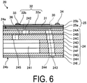
- FIG. 6 is a cross-sectional view taken along line A-A in FIG. 4 .
- the head main body 20 includes the flow channel member 24 and the piezoelectric actuator substrate 25.
- the flow channel member 24 includes a supply manifold 241, a plurality of pressurizing chambers 242, and the plurality of discharge holes 243.
- the plurality of pressurizing chambers 242 are connected to the supply manifold 241.
- the plurality of discharge holes 243 are connected to the plurality of pressurizing chambers 242, respectively.
- Each pressurizing chamber 242 opens to the first surface 24a (see FIG. 6 ) of the flow channel member 24. Furthermore, the first surface 24a of the flow channel member 24 has an opening 241a that connects to the supply manifold 241. Liquid is supplied from the supply member 21 (see FIG. 2 ), to the inside of the flow channel member 24 through the opening 241a.
- the head main body 20 has four supply manifolds 241 inside the flow channel member 24.
- the supply manifold 241 has an elongated shape extending along the longitudinal direction of the flow channel member 24.
- the opening 241a is located in the first surface 24a of the flow channel member 24 at either end of the supply manifold 241.
- the plurality of pressurizing chambers 242 are positioned in the flow channel member 24 in a two-dimensionally spreading manner.
- Each pressurizing chamber 242 is a hollow region having a substantially diamond-shaped planar shape with rounded corners.
- the pressurizing chamber 242 opens to the first surface 24a of the flow channel member 24, and is closed when the piezoelectric actuator substrate 25 is joined to the first surface 24a.
- the pressurizing chambers 242 form a pressurizing chamber row arranged in the longitudinal direction.
- the pressurizing chambers 242 in two adjacent pressurizing chamber rows are arranged alternately between the two pressurizing chamber rows.
- One pressurizing chamber group includes four pressurizing chamber rows connected to one supply manifold 241.
- the flow channel member 24 includes four pressurizing chamber groups.
- the relative internal arrangement of the pressurizing chambers 242 among the pressurizing chamber groups is the same, with the pressurizing chamber groups arranged while being slightly shifted from each other in the longitudinal direction.
- the discharge holes 243 are disposed at positions outside regions, of the flow channel member 24, facing the supply manifolds 241. Thus, no discharge hole 243 overlaps with the supply manifold 241 in a transparent view of the flow channel member 24 from the first surface 24a side.
- the discharge holes 243 are disposed within a region in which the piezoelectric actuator substrate 25 is provided.
- One group of such discharge holes 243 occupies a region of approximately the same size and shape as the piezoelectric actuator substrate 25.
- Droplets are discharged through the discharge holes 243 by displacing the displaced elements 30 (see FIG. 6 ), which are pressing units of the corresponding piezoelectric actuator substrate 25.
- the pressurizing chamber 242 and the supply manifold 241 are connected via an individual supply flow channel 245 (see FIG. 6 ).
- the individual supply flow channel 245 includes an aperture 36 with a smaller width than the other portions.
- the aperture 36 has a smaller width than the other portions of the individual supply flow channel 245, and thus has a high flow channel resistance. With the aperture 36 thus having a higher flow channel resistance, pressure produced in the pressurizing chamber 242 is less likely to escape to the supply manifold 241.
- the flow channel member 24 has a stack structure in which a plurality of plates are stacked. These plates include a cavity plate 24A, a base plate 24B, an aperture plate 24C, a supply plate 24D, manifold plates 24E, 24F, and 24G, a cover plate 24H, and a nozzle plate 241 arranged in this order from the upper surface of the flow channel member 24.
- the thickness of the plate is approximately 10 ⁇ m to 300 ⁇ m. With this configuration, the holes can be formed with high accuracy.
- the plates are stacked in alignment so that the holes communicate with each other to form an individual flow channel 244 and the supply manifold 241.
- the pressurizing chamber 242 is provided on the upper surface of the flow channel member 24, the supply manifold 241 is provided on the lower surface side of the interior, and the discharge holes 243 are provided in the lower surface, and portions forming the individual flow channel 244 are provided at different positions close to each other.
- the head main body 20 has a configuration in which the supply manifold 241 and the discharge hole 243 are connected to each other via the pressurizing chamber 242.
- the piezoelectric actuator substrate 25 includes piezoceramic layers 25a and 25b, a common electrode 31, an individual electrode 32, a connection electrode 33, a dummy connection electrode 34, and a surface electrode 35 (see FIG. 4 ).
- the piezoelectric actuator substrate 25 has the piezoceramic layer 25a, the common electrode 31, the piezoceramic layer 25b, and the individual electrode 32 stacked in this order.
- the piezoceramic layers 25a and 25b each have a thickness of approximately 20 ⁇ m. Either of the piezoceramic layers 25a and 25b extends across the plurality of pressurizing chambers 242.
- the piezoceramic layers 25a and 25b may each be made of a ferroelectric lead zirconate titanate (PZT)-based ceramic material.
- the common electrode 31 is positioned substantially entirely across the surface direction in the region between the piezoceramic layer 25a and the piezoceramic layer 25b. Thus, the common electrode 31 overlaps with all of the pressurizing chambers 242 in the region facing the piezoelectric actuator substrate 25.
- the thickness of the common electrode 31 is approximately 2 ⁇ m.
- a metal material such as an Ag-Pd based material can be used for the common electrode 31.
- the individual electrode 32 includes an individual electrode main body 32a and an extraction electrode 32b.
- the individual electrode main body 32a is positioned in a region, of the piezoceramic layer 25b, facing the pressurizing chamber 242.
- the individual electrode main body 32a has a shape that is one size smaller than that of the pressurizing chamber 242 and is substantially similar to that of the pressurizing chamber 242.
- the extraction electrode 32b is extracted from the individual electrode main body 32a.
- the connection electrode 33 is positioned at a portion, of one end of the extraction electrode 32b, that is extracted to be outside the region facing the pressurizing chamber 242.
- the individual electrode 32 may be made of, for example, a metal material such as an Au-based metal material.
- connection electrode 33 is positioned on the extraction electrode 32b, has a thickness of approximately 15 ⁇ m, and has a protruding shape.
- the connection electrode 33 is electrically bonded to an electrode provided in the signal transmission unit 26 (see FIG. 3 ).
- the connection electrode 33 may be made of, for example, silver-palladium, including glass frit.
- the dummy connection electrode 34 is positioned on the piezoceramic layer 25b and is positioned so as not to overlap with various electrodes such as the individual electrode 32.
- the dummy connection electrode 34 connects the piezoelectric actuator substrate 25 and the signal transmission unit 26 to each other, and increases the connection strength.
- the dummy connection electrode 34 makes uniform the distribution of the contact positions between the piezoelectric actuator substrate 25 and the piezoelectric actuator substrate 25, and stabilizes the electrical connection.
- the dummy connection electrode 34 need only be made of a material and by a process that are the same as those for the connection electrode 33.
- the surface electrode 35 is provided at a position on the piezoceramic layer 25b where the individual electrode 32 is not provided.
- the surface electrode 35 is connected to the common electrode 31 through a via hole located in the piezoceramic layer 25b. Thus, the surface electrode 35 is grounded and maintained at the ground potential.
- the surface electrode 35 need only be made of a material and by a process that are the same as those for the individual electrode 32.
- a plurality of the individual electrodes 32 are individually electrically connected to the control unit 14 (see FIG. 1 ) via the signal transmission unit 26 and wiring, in order to individually control the potentials of each individual electrode 32.
- the piezoceramic layer 25b sandwiched by the individual electrode 32 and the common electrode 31 serves as an active section.
- the individual electrode 32, the piezoceramic layer 25b, and the common electrode 31, facing the pressurizing chamber 242, function as the displaced elements 30.
- Unimorphic deformation of the displaced elements 30 results in the pressurizing chamber 242 being pressed and liquid to be discharged through the discharge hole 243.
- the individual electrode 32 is set to have a higher potential (hereinafter referred to as "high potential”) than the common electrode 31 in advance. Then, each time a discharge request is made, the individual electrode 32 is set to the same potential as the common electrode 31 (hereinafter referred to as "low potential”), and then is again set to the high potential at a predetermined timing.
- high potential a higher potential
- low potential the same potential as the common electrode 31
- the piezoceramic layers 25a and 25b return to their original shape, and the volume of the pressurizing chamber 242 increases over that in the initial state (a state where the potential differs between the two electrodes).
- the pressurizing chamber 242 is provided with negative pressure, whereby liquid is sucked from the supply manifold 241 side into the pressurizing chamber 242. Thereafter, at the timing when the individual electrode 32 is set to the high potential again, the piezoceramic layers 25a and 25b deform to protrude toward the pressurizing chamber 2452 side. Then, the volume in the pressurizing chamber 242 decreases, resulting in the pressurizing chamber 242 having positive pressure therein.
- the pulse width need only be an acoustic length (AL), corresponding to the length of time required for pressure waves to propagate from the aperture 36 to the discharge hole 243.
- A acoustic length
- the gradient is expressed based on the number of droplets continuously discharged from the discharge holes 243, that is, the amount (volume) of droplets adjusted based on the number of times the droplets are discharged.
- the droplets are discharged by a number of times corresponding to the designated gradient to be expressed, through the discharge holes 243 corresponding to the designated dot region.
- the interval between the pulses supplied for discharging the droplets may be designated as AL.
- periods match between a residual pressure wave of the pressure produced for the previous discharging of droplets and the pressure wave of the pressure produced for the subsequent discharging of the droplets.
- the residual pressure wave and the pressure wave are superimposed, whereby the droplets can be discharged with a higher pressure.
- the later discharging involves a higher speed of the droplets and a closer distance between the landing points of the plurality of droplets.
- FIG. 7 is a perspective view illustrating a flow channel configuration of the supply member 21 according to the first embodiment.
- FIG. 8 is an enlarged view of a first end 211 side in FIG. 7 .
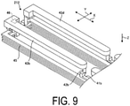
- FIG. 9 is an enlarged view of a second end 212 side in FIG. 7 .
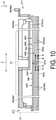
- FIG. 10 is a side view as viewed in a B1 direction in FIG. 7 .
- FIG. 11 is a side view as viewed in a B2 direction in FIG. 7 . Note that FIGS. 7 to 11 illustrate a space that serves as a flow channel.
- the configuration of an upstream side flow channel of the supply member 21 will be described with reference to FIGS. 7 to 9 .
- the supply member 21 is connected to the flow channel member 24 (see FIG. 6 ). As illustrated in FIG. 7 , the supply member 21 extends in a first direction X from the first end 211, which is a first end portion in the longitudinal direction, to the second end 212, which is a second end portion in the longitudinal direction.
- the supply member 21 includes a first supply flow channel 41, a first connection flow channel 42, and the reservoir 43.
- Liquid from a supply port 40 flows in the first supply flow channel 41.
- the first connection flow channel 42 is connected to the first supply flow channel 41.
- the liquid from the first supply flow channel 41 flows in the first connection flow channel 42.
- the reservoir 43 stores liquid from the first connection flow channel 42 and supplies this liquid to the flow channel member 24.
- the first connection flow channel 42 is connected to a surface of the reservoir 43 on the side of the second surface 24b (see FIG. 6 ) of the flow channel member 24 (the lower surface of the reservoir 43 in FIG. 7 ).
- the supply member 21 includes a plurality of the reservoirs 43.
- the supply member 21 includes two reservoir sets, that is, a first reservoir set 431 and a second reservoir set 432 each including two reservoirs 43 as a pair.
- the first reservoir set 431 includes a reservoir A (reservoir 43a) and a reservoir B (reservoir 43b).
- the reservoir 43a and the reservoir 43b respectively have equivalent substantially rectangular shapes, and are arranged in series in the first direction X with their longitudinal directions extending along the first direction X.
- the reservoir 43a is located on the first end 211 side and the reservoir 43b is located on the second end 212 side.
- the first reservoir set 431 of the supply member 21 includes, in addition to the reservoir 43a located on the first end 211 side, a supply port A (supply port 40a), a supply flow channel A (first supply flow channel 41a), and a connection flow channel A (first connection flow channel 42a).
- the supply port 40a is a liquid inlet into which liquid is supplied from upstream.
- the first supply flow channel 41a is connected to the supply port 40a.
- the first supply flow channel 41a includes a portion (extending portion 411) extending in the first direction X.
- the first connection flow channel 42a is connected to the first supply flow channel 41a.
- the reservoir 43a is connected to the first connection flow channel 42a.
- the first connection flow channel 42a is connected to the second surface 24b side of the reservoir 43a.
- the first connection flow channel 42a is connected to the second end 212 side of the reservoir 43a.
- the first supply flow channel 41a includes a portion (bent portion 412) extending in a second direction Y that intersects with (e.g., is orthogonal to) the first direction X on the second end 212 side.
- the bent portion 412 is connected to the first connection flow channel 42a.
- the first reservoir set 431 of the supply member 21 includes, in addition to the reservoir 43b located on the second end 212 side, a supply port B (supply port 40b), a supply flow channel B (first supply flow channel 41b), and a connection flow channel B (first connection flow channel 42b).
- the supply port 40b is a liquid inlet into which liquid is supplied from upstream.
- the first supply flow channel 41b is connected to the supply port 40b.
- the first connection flow channel 42b is connected to the first supply flow channel 41b.
- the reservoir 43b is connected to the first connection flow channel 42b.
- the first connection flow channel 42b is connected to the second surface 24b side of the reservoir 43b.
- the first connection flow channel 42b is connected to the first end 211 side of the reservoir 43b.
- the first supply flow channel 41b extends along the first direction X.
- the supply port 40a and the supply port 40b, serving as the interface of the supply member 21, are each located on the first end 211 side.
- the second reservoir set 432 includes a reservoir C (reservoir 43c) and a reservoir D (reservoir 43d).
- the reservoir 43c and the reservoir 43d respectively have equivalent substantially rectangular shapes, and are arranged in series in the first direction X with their longitudinal directions extending along the first direction X.
- the reservoir 43c is located on the first end 211 side and the reservoir 43d is located on the second end 212 side.
- the reservoir 43c faces the reservoir 43a in the direction (second direction Y) orthogonal to the first direction X with a space in between, and the reservoir 43d faces the reservoir 43b in the second direction Y with a space in between.
- the second reservoir set 432 is symmetrical with respect to the first reservoir set 431 about the second direction Y, and as in the first reservoir set 431 described above, has the reservoir 43c and the reservoir 43d each including the supply port 40, the supply flow channel (first supply flow channel) 41, and the connection flow channel (first connection flow channel) 42.
- a supply port 40c and a supply port 40d, serving as the interface of the supply member 21, are each located on the first end 211 side. In other words, the interface of the supply member 21 is concentrated on the first end 211 side.
- the supply member 21 includes a second connection flow channel 44 and a second supply flow channel 45.
- the second connection flow channel 44 and the second supply flow channel 45 are flow channels through which liquid flows from the reservoir 43 toward the flow channel member 24 (see FIG. 6 ).
- the second connection flow channel 44 and the second supply flow channel 45 are arranged in this order in the direction from the reservoir 43 toward the flow channel member 24, that is, from the upstream side.
- the second connection flow channel 44 is connected to the reservoir 43.
- the second connection flow channel 44 is connected to a surface of the reservoir 43 on the side of the second surface 24b of the flow channel member 24 (the lower surface of the reservoir 43 in FIG. 7 ).
- the second supply flow channel 45 is connected to the second connection flow channel 44.
- the second supply flow channel 45 supplies liquid toward the flow channel member 24.
- the supply member 21 includes a filter 46.
- the filter 46 is located between the reservoir 43 and the second connection flow channel 44.
- the first connection flow channel 42 is connected to the second surface 24b side of the reservoir 43.
- the direction in which the liquid is supplied to the reservoir 43 is the same as the direction of buoyancy acting on the bubbles.
- the bubbles are less likely to remain in the first connection flow channel 42, whereby the hindering of the liquid flow by the bubbles can be suppressed.
- insufficient supply of liquid to the reservoir 43 can be prevented.
- the supply port 40a of the reservoir 43a and the supply port 40b of the reservoir 43b are both located on the first end 211 side, and thus the two supply ports 40a and 40b can be connected to the respective supply sources from the first end 211 side. This facilitates the operation of incorporating the head main body 20 into the printer 1, whereby productivity can be improved.
- bent portion 412 extending in the second direction Y is provided in the first supply flow channel 41a close to the supply port 40a, so that the first supply flow channel 41a and the first supply flow channel 41b can have approximately equal flow channel lengths, whereby pressure loss during flow to the reservoirs 43a and 43b can be approximated.
- the first supply flow channel 41b far from the supply port 40b extends in the first direction X, the first supply flow channel 41b can have a minimum flow channel length, and the pressure loss in the reservoir 43b can be reduced.
- the second connection flow channel 44 supplying liquid toward the flow channel member 24 is connected to a second surface 21b side of the reservoir 43, whereby bubbles that have entered the reservoir 43 can be prevented from entering a downstream side flow channel such as the second connection flow channel 44 or the second supply flow channel 45. Even if the bubbles enter the second connection flow channel 44 and the second supply flow channel 45, the bubbles easily return to the reservoir 43, whereby the bubbles are less likely to remain in the downstream side flow channel.
- the filter 46 is located between the reservoir 43 and the second connection flow channel 44, so that foreign matter can be removed. Further, the entry of foreign matter into the downstream side flow channel, such as the second connection flow channel 44 or the second supply flow channel 45, can be suppressed.
- FIGS. 10 and 11 The configuration of a downstream side flow channel of the supply member 21 will be described with reference to FIGS. 10 and 11 . Note that in FIGS. 10 and 11 , one of the two reservoirs 43a and 43b (the reservoir 43b and the flow channel around the reservoir 43b) is hatched. As illustrated in FIGS. 10 and 11 , the supply member 21 includes the supply port 40, the first supply flow channel 41, the reservoir 43, and the second supply flow channel 45.
- a heater 37 is located on the supply member 21.
- the heater 37 is located on the upper surface of the supply member 21 corresponding to the two reservoirs 43a and 43b and warms the liquid inside the two reservoirs 43a and 43b.
- the heater 37 is also located on the two reservoirs 43c and 43d.
- the first supply flow channel 41 is connected to the supply port 40, and the reservoir 43 is connected to the first supply flow channel 41.
- the second supply flow channel 45 is connected to the reservoir 43 and the flow channel member 24 (see FIG. 6 ).
- the supply member 21 at least includes the reservoir 43a, a second supply flow channel A (second supply flow channel 45a), the reservoir 43b, and a second supply flow channel B (second supply flow channel 45b).
- the second supply flow channel 45a is connected to the reservoir 43a and the flow channel member 24.
- the second supply flow channel 45b is connected to the reservoir 43b and the flow channel member 24.
- the supply member 21 includes a first overlapping region AR1 in which the second supply flow channel 45a and the second supply flow channel 45b overlap, in the flow channel on the downstream side of the reservoir 43.
- the first overlapping region AR1 the second supply flow channel 45a and the second supply flow channel 45b overlap as viewed in the third direction Z.
- the second supply flow channel 45a includes a branch portion A (branch portion 451a) and a branch flow channel A (branch flow channel 452a).
- the branch flow channel 452a is located more on the downstream side than the branch portion 451a.
- the second supply flow channel 45b includes a branch portion B (branch portion 451b) and a branch flow channel B (branch flow channel 452b).
- the branch flow channel 452b is located more on the downstream side than the branch portion 451b.
- the supply member 21 includes a second overlapping region AR2 in which the branch flow channel 452a and the branch flow channel 452b overlap, in the flow channel on the downstream side of the reservoir 43.
- the branch flow channel 452a and the branch flow channel 452b overlap as viewed in the third direction Z.
- liquid Ia flowing in the branch flow channel 452a and liquid Ib flowing in the branch flow channel 452b flow as parallel flows.
- Parallel flow means that the liquid Ia and the liquid Ib flow in the same direction.
- the liquid Ia and the liquid Ib flow in the same direction in the first direction X as viewed in the second direction Y (see FIG. 7 ).
- the liquid Ia flowing in the branch flow channel 452a and the liquid Ib flowing in the branch flow channel 452b may be configured to flow as counter flows.
- Counter flow means that the liquid Ia and the liquid Ib flow in different directions.
- the liquid Ia and the liquid Ib flow in different directions in the first direction X as viewed in the second direction Y.
- the supply member 21 includes a connection flow channel (second connection flow channel) 44a.
- the second connection flow channel 44a has one end connected to the reservoir 43a and the other end connected to the branch flow channel 452a.
- the supply member 21 includes a third overlapping region AR3 in which the second connection flow channel 44a and the branch flow channel 452b overlap, in the flow channel on the downstream side of the reservoir 43a located at the first end 211. Note that the overlapping in the third overlapping region AR3 occurs as viewed in the third direction Z.
- the supply member 21 includes a second connection flow channel 44b.
- the second connection flow channel 44b has one end connected to the reservoir 43b and the other end connected to the branch flow channel 452b.
- the supply member 21 includes a fourth overlapping region AR4 in which the second connection flow channel 44b and the branch flow channel 452a overlap, in the flow channel on the downstream side of the reservoir 43b located at the second end 212. Note that the overlapping in the fourth overlapping region AR4 occurs as viewed in the third direction Z.
- the supply member 21 includes a fifth overlapping region AR5 in which the first supply flow channel 41a connected to the supply port 40a and the second connection flow channel 44b overlap as illustrated in FIG. 11 , in the flow channel on the downstream side of the reservoir 43a located at the first end 211. Note that the overlapping in the fifth overlapping region AR5 occurs as viewed in the third direction Z.
- the supply member 21 includes a sixth overlapping region AR6 in which the first supply flow channel 41b connected to the supply port 40b and the second connection flow channel 44a overlap as illustrated in FIG. 11 , in the flow channel on the downstream side of the reservoir 43b located at the second end 212. Note that the overlapping in the sixth overlapping region AR6 occurs as viewed in the third direction Z.
- liquid can exchange heat with another liquid at least between a plurality of systems (two systems) including the reservoir 43a and the reservoir 43b. This contributes to the uniformization of the temperature of the liquid on the downstream side of the reservoirs 43a and 43b. As a result, degradation of the discharge performance of the liquid can be suppressed.
- the first overlapping region AR1 in which the second supply flow channel 45a and the second supply flow channel 45b overlap is provided to contribute to the uniformization of the temperatures of the liquids on the downstream side of the reservoirs 43a and 43b, the reservoirs 43a and 43b do not need to overlap each other. As a result, the thickness of the supply member 21 in the third direction Z is less likely to increase.
- liquid can exchange heat with another liquid between a plurality of systems (two systems) as described above to contribute to the uniformization of the liquid temperature.
- the liquid Ia flowing in the branch flow channel 452a and the liquid Ib flowing in the branch flow channel 452b flow as parallel flows.
- the liquid Ia and the liquid Ib flowing in the two branch flow channels 452a and 452b flow in the same direction while exchanging heat.
- an attempt to uniformize the temperatures of the liquid Ia and the liquid Ib can be facilitated.
- the liquid Ia flowing in the branch flow channel 452a and the liquid Ib flowing in the branch flow channel 452b flow as counter flows
- the liquid Ia and the liquid Ib flowing in the two branch flow channels 452a and 452b flow while exchanging heat as in the case of the parallel flow, whereby an attempt to uniformize the temperatures of the liquid Ia and the liquid Ib can be facilitated.
- the liquid flowing in the second connection flow channel 44a can be pre-heated with the temperature of the liquid flowing in the branch flow channel 452b. As a result, an attempt to uniformize the temperatures of the liquids can be facilitated.
- the liquid flowing in the second connection flow channel 44b can be pre-heated with the temperature of the liquid flowing in the branch flow channel 452a. As a result, an attempt to uniformize the temperatures of the liquids can be facilitated.
- the liquid flowing in the first supply flow channel 41a can be pre-heated with the temperature of the liquid flowing in the second connection flow channel 44b, whereby an attempt to uniformize the temperatures of the liquids can be facilitated.
- the liquid flowing in the first supply flow channel 41b can be pre-heated with the temperature of the liquid flowing in the second connection flow channel 44a, whereby an attempt to uniformize the temperatures of the liquids can be facilitated.
- the supply member 21 includes the first to sixth overlapping regions AR1 to AR6 to implement efficient heat exchange.
- overlapping areas of the first to sixth overlapping regions AR1 to AR6 need only be increased.
- the branch flow channel 452a and the branch flow channel 452b need only extend along each other in the second direction Y.
- the overlapping flow channels may be adjacent to each other in the third direction Z.
- efficient heat exchange can be achieved with the first to sixth overlapping regions AR1 to AR6.
- the supply member 21 is made of a metal, an alloy, or a thermosetting resin.
- the metal material include stainless steel such as SUS430.
- thermosetting resins include thermosetting epoxy resins including glass fibers and inorganic fillers.
- the thermal conductivity of the thermosetting epoxy resin including glass fibers or inorganic fillers may be from 0.3 to 0.7 w/m ⁇ K. Note that the coefficient of thermal expansion may be measured by a coefficient of linear expansion test method using thermomechanical analysis of plastic as defined in JIS K7197, for example.
- FIG. 12 is an explanatory view of a space.
- the supply member 21 extends in the first direction X from the first end to the second end.
- the reservoirs 43a to 43d include the first reservoir set that is a combination of the reservoir 43a and the reservoir 43b arranged in the first direction X with respect to the reservoir 43a, and the second reservoir set that is a combination of the reservoir 43c that faces the reservoir 43a in a direction orthogonal to the first direction X with a space in between and the reservoir 43d arranged in the first direction X with respect to the reservoir 43c.
- an inner region of the supply member 21 as viewed in a direction perpendicular to the first surface 24a of the flow channel member 24, surrounded by the first reservoir set (the reservoir 43a and the reservoir 43b) and the second reservoir set (the reservoir 43c and the reservoir 43d) may be provided with a space 213 that extends through the first surface 24a in the direction perpendicular to the first surface 24a.
- the liquid discharge head includes a circuit substrate
- the circuit substrate stands on the surface of the supply member 21 on the side provided with the first reservoir set (the reservoir 43a and the reservoir 43b) and the second reservoir set (the reservoir 43c and the reservoir 43d) as described later, heat transfer from the IC of the circuit substrate to the reservoirs 43a to 43d and the supply flow channels respectively connected thereto can be suppressed.
- the outer circumference of the space 213 may extend along the first reservoir set (the reservoir 43a and the reservoir 43b) and the second reservoir set (the reservoir 43c and the reservoir 43d) and be located on the outer side of an actuator substrate (piezoelectric actuator substrate 25), as viewed in the direction perpendicular to the first surface 24a of the flow channel member 24.
- an FPC is used as the signal transmission unit 26 that supplies a signal to each of the displaced elements 30 of the piezoelectric actuator substrate 25 serving as the actuator substrate.
- FIG. 13 is an explanatory view of a substrate arrangement. As illustrated in FIG. 13 , the circuit substrate 22 is positioned between the first reservoir set 431 and the second reservoir set 432, as viewed in the third direction Z (plan view) orthogonal to each of the first direction X and the second direction Y.
- the reservoirs 43a to 43d are not located directly below the circuit substrate 22, whereby the reservoirs 43a to 43d are less likely to be affected by heat from the circuit substrate 22.
- heat from a source other than the heater 37 is less likely to be transferred to the reservoirs 43a to 43d.
- the temperature of the liquid can be precisely controlled.
- FIG. 14 is a perspective view illustrating a flow channel configuration of the supply member 210 according to the second embodiment.
- FIG. 15 is an enlarged view of the first end 211 side in FIG. 14 .
- FIG. 16 is an enlarged view of the second end 212 side in FIG. 14 .
- FIG. 17 is a cross-sectional view taken along line C1-C1 in FIG. 16 .
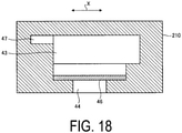
- FIG. 18 is a cross-sectional view taken along line C2-C2 in FIG. 16 .
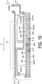
- FIG. 19 is a side view in a D1 direction in FIG. 14 .
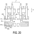
- FIG. 20 is a side view in a D2 direction in FIG. 14 . Note that FIGS. 13 to 16 , FIG. 19 , and FIG. 20 illustrate a space to serve as a flow channel.
- the configuration of the supply member 210 according to the second embodiment is primarily different from that of the first embodiment described above in that a discharge flow channel 47 and a discharge port 48 for bubbles are provided. As illustrated in FIG. 14 , the supply member 210 includes the discharge flow channel 47 for discharging bubbles from the reservoir 43.
- the discharge flow channel 47 is connected to the first surface 24a (see FIG. 6 ) side of the reservoir 43, with respect to the second surface 24b (see FIG. 6 ).
- the discharge flow channel 47 is connected to the outer side surface of the reservoir 43 in the first direction X.
- discharge flow channels 47a to 47d the discharge flow channels 47a and 47c protrude from the reservoirs 43a and 43d toward the first end 211 side along the first direction X, respectively.
- the discharge flow channels 47a and 47c are connected to the first end 211 side of the reservoirs 43a and 43c as viewed in the third direction Z, respectively.
- the discharge flow channels 47a to 47d protrude from the reservoir 43 toward the second end 212 side along the first direction X, respectively, are bent to extend in the second direction Y, and are further bent to extend in the first direction X toward the first end 211 side.
- discharge ports 48a to 48d are located at respective first end 211 side, that is, downstream side end portions of the discharge flow channels 47a to 47d, respectively.
- the supply ports 40a to 40d and the discharge ports 48a to 48d are located on the first end 211 side, whereby the interface is concentrated on the first end 211 side.
- the supply member 21 includes the filter 46. As illustrated in FIG. 17 , the filter 46 is located between the reservoir 43 (43c) and the second connection flow channel 44.
- the discharge flow channel 47 is located at the same level as the surface of the reservoir 43 on the first surface 24a side (the upper surface in FIGS. 16 and 17 ), or is located more on the first surface 24a side than the surface on the first surface 24a side.
- the discharge flow channel 47 is continuous and flush with the upper surface of the reservoir 43.
- the discharge flow channel 47 may be connected to the upper surface of the reservoir 43 so as to be higher than the upper surface.
- the discharge flow channel 47 is located on the filter 46, that is, immediately on the downstream side of the filter 46.
- Such a second embodiment provides the same effects as the first embodiment described above, and also provides an additional effect that bubbles in the reservoir 43 can be discharged to the outside through the discharge flow channel 47 for discharging the bubbles.
- discharge flow channel 47 is connected to the first surface 24a side of the reservoir 43, and the discharge flow channel 47 is located at the same level as the surface of the reservoir 43 on the first surface 24a side or located more on the first surface 24a side than the surface on the first surface 24a side, the bubbles in the reservoir 43 are smoothly discharged.
- discharge flow channel 47 is located immediately on the downstream side of the filter 46, even when bubbles in the reservoir 43 are trapped by the filter 46, such trapped bubbles can be efficiently collected and discharged.
- FIGS. 19 and 20 A configuration of a downstream side flow channel of the supply member 21 will be described with reference to FIGS. 19 and 20 .
- the supply member 210 includes the first overlapping region AR1 in which the second supply flow channel 45a and the second supply flow channel 45b overlap, in the flow channel on the downstream side of the reservoir 43.
- the supply member 210 includes the second overlapping region AR2 in which the branch flow channel 452a and the branch flow channel 452b overlap, in the flow channel on the downstream side of the reservoir 43.
- the liquid Ia flowing in the branch flow channel 452a and the liquid Ib flowing in the branch flow channel 452b flow as parallel flows.
- the liquid Ia flowing in the branch flow channel 452a and the liquid Ib flowing in the branch flow channel 452b may be configured to flow as counter flows.
- the supply member 210 includes the third overlapping region AR3 in which the second connection flow channel 44a and the branch flow channel 452b overlap, in the flow channel on the downstream side of the reservoir 43a located at the first end 211.
- the supply member 210 includes the fourth overlapping region AR4 in which the second connection flow channel 44b and the branch flow channel 452a overlap, in the flow channel on the downstream side of the reservoir 43b located at the second end 212.
- the supply member 210 includes the fifth overlapping region AR5 in which the first supply flow channel 41a connected to the supply port 40a and the second connection flow channel 44b overlap as illustrated in FIG. 20 , in the flow channel on the downstream side of the reservoir 43a located at the first end 211.
- the supply member 210 includes the sixth overlapping region AR6 in which the first supply flow channel 41b connected to the supply port 40b and the second connection flow channel 44a overlap as illustrated in FIG. 20 , in the flow channel on the downstream side of the reservoir 43b located at the second end 212.
- liquid can exchange heat with another liquid between a plurality of systems (two systems) as in the first embodiment. This contributes to the uniformization of the temperatures of the liquids on the downstream side of the reservoirs 43a and 43b. As a result, degradation of the discharge performance of the liquid can be suppressed.
- the first overlapping region AR1 in which the second supply flow channel 45a and the second supply flow channel 45b overlap is provided to contribute to the uniformization of the temperatures of the liquids on the downstream side of the reservoirs 43a and 43b, the reservoirs 43a and 43b do not need to overlap each other. As a result, the thickness of the supply member 21 in the third direction Z is less likely to increase.
- liquid can exchange heat with another liquid between a plurality of systems (two systems) as described above to contribute to the uniformization of the liquid temperature.
- the liquid Ia flowing in the branch flow channel 452a and the liquid Ib flowing in the branch flow channel 452b flow as parallel flows, the liquid Ia and the liquid Ib flowing in the two branch flow channels 452a and 452b flow in the same direction while exchanging heat, whereby an attempt to uniformize the temperatures of the liquid Ia and the liquid Ib can be facilitated.
- the liquid Ia flowing in the branch flow channel 452a and the liquid Ib flowing in the branch flow channel 452b flow as counter flows
- the liquid Ia and the liquid Ib flowing in the two branch flow channels 452a and 452b flow while exchanging heat as in the case of the parallel flow, whereby an attempt to uniformize the temperatures of the liquid Ia and the liquid Ib can be facilitated.
- the liquid flowing in the second connection flow channel 44a can be pre-heated with the temperature of the liquid flowing in the branch flow channel 452b. As a result, an attempt to uniformize the temperatures of the liquids can be facilitated.
- the liquid flowing in the second connection flow channel 44b can be pre-heated with the temperature of the liquid flowing in the branch flow channel 452a. As a result, an attempt to uniformize the temperatures of the liquids can be facilitated.
- the liquid flowing in the first supply flow channel 41a can be pre-heated with the temperature of the liquid flowing in the second connection flow channel 44b, whereby an attempt to uniformize the temperatures of the liquids can be facilitated.
- the liquid flowing in the first supply flow channel 41b can be pre-heated with the temperature of the liquid flowing in the second connection flow channel 44a, whereby an attempt to uniformize the temperatures of the liquids can be facilitated.
- the recording apparatus (printer 1) includes the liquid discharge heads 8, the conveying unit (conveying rollers 6) configured to convey the recording medium (printing sheet P) to the liquid discharge heads 8, and the control unit 14 configured to control the liquid discharge heads 8, as described above.
- the control unit 14 configured to control the liquid discharge heads 8, as described above.
- the recording apparatus (printer 1) includes the liquid discharge heads 8 and the applicator 4 that applies the coating agent on the recording medium (printing sheet P), as described above.
- the printing quality of the printer 1 can be improved.
- the recording apparatus printer 1 according to the embodiment includes the liquid discharge head 8 and the dryer 10 that dries the recording medium (printing sheet P), as described above. With this configuration, it is possible to suppress bonding between the printing sheets P rolled while overlapping each other and rubbing of undried liquid at the collection roller 13.
Landscapes
- Particle Formation And Scattering Control In Inkjet Printers (AREA)
- Ink Jet (AREA)
Abstract
Description
- The disclosed embodiments relate to a liquid discharge head and a recording apparatus.
- Known printing apparatuses include inkjet printers and inkjet plotters that utilize an inkjet recording method. An inkjet printing apparatus is installed with a liquid discharge head for discharging a liquid.
- The liquid discharge head includes a flow channel member having a plurality of discharge holes, and a supply member connected to the flow channel member. Of these, the supply member includes a supply flow channel and a reservoir that stores liquid from the supply flow channel, and has a flow channel configuration for supplying the liquid to the reservoir from a direction intersecting with a direction in which gravity acts (see, for example, Patent Literature 1).
- Patent Literature 1:
Japanese Patent No. 4432925 - Unfortunately, in the known liquid discharge head as described above, when bubbles are mixed in the supply flow channel, the bubbles may remain in the supply flow channel due to a difference in the direction of buoyancy acting on the bubbles and the direction in which the liquid is supplied to the reservoir. The bubbles remaining in the supply flow channel may hinder the flow of liquid, resulting in insufficient supply of liquid to the reservoir.
- An aspect of an embodiment of the present invention has been made in view of the above, and an object of the present invention is to provide a liquid discharge head and a recording apparatus capable of preventing insufficient supply of liquid to a reservoir.
- A liquid discharge head according to an aspect of the present invention includes: a flow channel member including a first surface and a second surface located opposite to the first surface; a pressing unit located on the first surface; and a supply member connected to the flow channel member. The flow channel member includes a plurality of discharge holes located in the second surface. The supply member includes, in this order from an upstream side, a first supply flow channel; a first connection flow channel connected to the first supply flow channel; and a reservoir connected to the first connection flow channel. The first connection flow channel is connected to the second surface side of the reservoir.
- A recording apparatus according to an aspect of the present invention includes: a flow channel member including a first surface and a second surface located opposite to the first surface; a pressing unit located on the first surface; and a supply member connected to the flow channel member. The flow channel member includes a plurality of discharge holes located in the second surface. The supply member includes, in this order from an upstream side, a first supply flow channel; a first connection flow channel connected to the first supply flow channel; and a reservoir connected to the first connection flow channel. The first connection flow channel includes: a liquid discharge head connected to the second surface side of the reservoir; a conveying unit configured to convey a recording medium to the liquid discharge head; and a control unit configured to control the liquid discharge head.
- According to one aspect of an embodiment of the present invention, insufficient supply of liquid to the reservoir can be prevented.
-
-
FIG. 1 is an explanatory view (1) of a recording apparatus according to an embodiment. -
FIG. 2 is an explanatory view (2) of the recording apparatus according to the embodiment. -
FIG. 3 is an exploded perspective view illustrating a schematic configuration of a liquid discharge head according to the embodiment. -
FIG. 4 is an enlarged plan view of the liquid discharge head illustrated inFIG. 3 . -
FIG. 5 is an enlarged view of a region in the dot-dash line inFIG. 4 . -
FIG. 6 is a cross-sectional view taken along line A-A inFIG. 4 . -
FIG. 7 is a perspective view illustrating a flow channel configuration of a supply member according to a first embodiment. -
FIG. 8 is an enlarged view of a first end side inFIG. 7 . -
FIG. 9 is an enlarged view of a second end side inFIG. 7 . -
FIG. 10 is a side view as viewed in a B1 direction illustrated inFIG. 7 . -
FIG. 11 is a side view as viewed in a B2 direction illustrated inFIG. 7 . -
FIG. 12 is an explanatory view of a space. -
FIG. 13 is an explanatory view of a substrate arrangement. -
FIG. 14 is a perspective view illustrating a flow channel configuration of a supply member according to a second embodiment. -
FIG. 15 is an enlarged view of a first end side inFIG. 14 . -
FIG. 16 is an enlarged view of a second end side inFIG. 14 . -
FIG. 17 is a cross-sectional view taken along line C1-C1 inFIG. 16 . -
FIG. 18 is a cross-sectional view taken along line C2-C2 inFIG. 16 . -
FIG. 19 is a side view as viewed in a D1 direction illustrated inFIG. 14 . -
FIG. 20 is a side view as viewed in a D2 direction illustrated inFIG. 14 . - Embodiments of a liquid discharge head and a recording apparatus disclosed in the present application will be described in detail below with reference to the accompanying drawings. Note that the present invention is not limited by the embodiments described below.
- First, with reference to
FIG. 1 andFIG. 2 , a description will be given of an overview of aprinter 1 serving as an example of a recording apparatus according to an embodiment.FIGS. 1 and2 are explanatory views of theprinter 1 according to the embodiment. Specifically,FIG. 1 is a schematic side view of theprinter 1 andFIG. 2 is a schematic plan view of theprinter 1. Theprinter 1 according to the embodiment is, for example, a color inkjet printer. - As illustrated in
FIG. 1 , theprinter 1 includes apaper feed roller 2,guide rollers 3, anapplicator 4, ahead case 5, a plurality ofconveying rollers 6, a plurality offrames 7, a plurality ofliquid discharge heads 8,conveying rollers 9, adryer 10,conveying rollers 11, asensor unit 12, and acollection roller 13. Theconveying rollers 6 are examples of a conveying unit. - The
printer 1 includes acontrol unit 14 that controls thepaper feed roller 2, theguide rollers 3, theapplicator 4, thehead case 5, the plurality ofconveying rollers 6, the plurality offrames 7, the plurality ofliquid discharge heads 8, theconveying rollers 9, thedryer 10, theconveying rollers 11, thesensor unit 12, and thecollection roller 13. - The
printer 1 records an image and characters on a printing sheet P by causing droplets to land on the printing sheet P. The printing sheet P is an example of a recording medium. The printing sheet P is rolled on thepaper feed roller 2 prior to use. In this state, theprinter 1 conveys the printing sheet P from thepaper feed roller 2 to the inside of thehead case 5 via theguide rollers 3 and theapplicator 4. - The
applicator 4 uniformly applies a coating agent over the printing sheet P. With surface treatment thus performed on the printing sheet P, the printing quality of theprinter 1 can be improved. - The
head case 5 houses the plurality ofconveying rollers 6, the plurality offrames 7, and the plurality ofliquid discharge heads 8. The inside of thehead case 5 is formed with a space separated from the outside except for a part connected to the outside such as parts where the printing sheet P enters and exits. - If necessary, the
control unit 14 controls at least one of controllable factors of the internal space of thehead case 5, such as the temperature, the humidity, and barometric pressure. Theconveying rollers 6 convey the printing sheet P to the vicinity of theliquid discharge heads 8, inside thehead case 5. - The
frame 7 is a rectangular flat plate, and is positioned above and close to the printing sheet P conveyed by the conveyingrollers 6. As illustrated inFIG. 2 , theframes 7 are positioned such that the longitudinal direction of theframes 7 is orthogonal to the conveyance direction of the printing sheet P. Furthermore, the plurality of (e.g., four)frames 7 are located inside thehead case 5 along the conveyance direction of the printing sheet P. - Liquid, which is ink for example, is supplied to the liquid discharge heads 8 from a liquid tank (not illustrated). The liquid discharge heads 8 discharge the liquid supplied from the liquid tank.
- The
control unit 14 controls the liquid discharge heads 8 based on data of an image, characters, and the like to discharge the liquid toward the printing sheet P. The distance between eachliquid discharge head 8 and the printing sheet P is, for example, approximately 0.5 mm to 20 mm. - The liquid discharge heads 8 are fixed to the
frame 7. The liquid discharge heads 8 are positioned such that the longitudinal direction of the liquid discharge heads 8 is orthogonal to the conveyance direction of the printing sheet P. - That is, the
printer 1 according to the embodiment is what is known as a line printer with the liquid discharge heads 8 fixed inside theprinter 1. Note that theprinter 1 according to the embodiment is not limited to a line printer and may also be what is known as a serial printer. - The serial printer is a printer employing a method of alternately performing operations of recording while moving the liquid discharge heads 8 in a manner such as reciprocation in a direction intersecting (e.g., substantially orthogonal to) the conveyance direction of the printing sheet P, and conveying the printing sheet P.
- As illustrated in
FIG. 2 , a plurality of (e.g., five) liquid discharge heads 8 are fixed to oneframe 7.FIG. 2 illustrates an example in which three liquid discharge heads 8 are located on the forward side and two liquid discharge heads 8 are located on the rear side, in the conveyance direction of the printing sheet P. Further, the liquid discharge heads 8 are positioned without their centers overlapping in the conveyance direction of the printing sheet. - The plurality of liquid discharge heads 8 positioned in one
frame 7 form ahead group 8A. Fourhead groups 8A are positioned along the conveyance direction of the printing sheet P. The liquid discharge heads 8 belonging to thesame head group 8A are supplied with ink of the same color. As a result, theprinter 1 can perform printing with four colors of ink using the fourhead groups 8A. - The colors of the ink discharged from the
respective head groups 8A are, for example, magenta (M), yellow (Y), cyan (C), and black (K). Thecontrol unit 14 can print a color image on the printing sheet P by controlling each of thehead groups 8A to discharge the plurality of colors of ink onto the printing sheet P. - Note that a surface treatment may be performed on the printing sheet P, by discharging a coating agent from the
liquid discharge head 8 onto the printing sheet P. - Furthermore, the number of the liquid discharge heads 8 included in one
head group 8A and the number of thehead groups 8A provided in theprinter 1 can be changed as appropriate in accordance with printing targets and printing conditions. For example, if the color to be printed on the printing sheet P is a single color and the range of the printing can be covered by a singleliquid discharge head 8, only a singleliquid discharge head 8 may be provided in theprinter 1. - The printing sheet P thus subjected to the printing process inside the
head case 5 is conveyed by the conveyingrollers 9 to the outside of thehead case 5, and passes through the inside of thedryer 10. Thedryer 10 dries the printing sheet P after the printing process. The printing sheet P thus dried by thedryer 10 is conveyed by the conveyingrollers 11 and then collected by thecollection roller 13. - In the
printer 1, by drying the printing sheet P with thedryer 10, it is possible to suppress bonding between the printing sheets P rolled while being overlapped with each other, and rubbing between undried liquid at thecollection roller 13. - The
sensor unit 12 includes a position sensor, a speed sensor, a temperature sensor, and the like. Based on information from thesensor unit 12, thecontrol unit 14 can determine the state of each part of theprinter 1 and control each part of theprinter 1. - In the
printer 1 described above, the printing sheet P is the printing target (i.e., the recording medium), but the printing target in theprinter 1 is not limited to the printing sheet P, and a roll type fabric or the like may be the printing target. - Furthermore, instead of directly conveying the printing sheet P, the
printer 1 may be mounted on a conveyor belt and then conveyed. If a conveyor belt is used, the printing target of theprinter 1 can be flat paper, cut cloth, wood, tile, or the like. - Furthermore, the
printer 1 may discharge a liquid containing electrically conductive particles from theliquid discharge head 8, to print a wiring pattern or the like of an electronic device. Furthermore, theprinter 1 may discharge liquid containing a predetermined amount of liquid chemical agent or liquid containing the chemical agent from theliquid discharge head 8 onto a reaction vessel or the like to produce chemicals. - The
printer 1 may also include a cleaning unit for cleaning the liquid discharge heads 8. The cleaning unit cleans the liquid discharge heads 8 by, for example, a wiping process or a capping process. - The wiping process is, for example, a process of removing liquid attached to a
second surface 24b (seeFIG. 3 ) of a flow channel member 24 (seeFIG. 3 ), which is an example of a surface of a portion onto which the liquid is discharged, by rubbing thesecond surface 24b with a flexible wiper. - The capping process is performed as follows, for example. First of all, a cap is provided to cover the
second surface 24b of theflow channel member 24 which is an example of the portion onto which the liquid is discharged (this action is referred to as capping). As a result, a substantially sealed space is formed between thesecond surface 24b and the cap. - The discharge of liquid is then repeated in such a sealed space. As a result, liquid with a viscosity higher than that in the normal state, foreign matter, or the like clogging discharge holes 243 (see
FIG. 6 ) can be removed. - Next, the configuration of the
liquid discharge head 8 according to the embodiment will be described with reference toFIG. 3. FIG. 3 is an exploded perspective view illustrating a schematic configuration of theliquid discharge head 8 according to the embodiment. - As illustrated in
FIG. 3 , theliquid discharge head 8 includes a headmain body 20, asupply member 21, acircuit substrate 22, and ahead cover 23. The headmain body 20 includes theflow channel member 24, apiezoelectric actuator substrate 25, asignal transmission unit 26, and adrive IC 27. - The
flow channel member 24 of the headmain body 20 has a substantially flat plate shape and includes afirst surface 24a, which is one main surface, and thesecond surface 24b located on a side opposite to thefirst surface 24a. Thefirst surface 24a has anopening 241a (seeFIG. 4 ), and a liquid is supplied into theflow channel member 24 from thesupply member 21 described later through theopening 241a. - A plurality of the discharge holes 243 (see
FIG. 4 ) that discharge liquid onto the printing sheet P are located on thesecond surface 24b. Furthermore, a flow channel through which liquid flows from thefirst surface 24a to thesecond surface 24b is located inside theflow channel member 24. - The
piezoelectric actuator substrate 25 is located on thefirst surface 24a of theflow channel member 24. Thepiezoelectric actuator substrate 25 includes a plurality of the displaced elements 30 (seeFIG. 6 ). The displacedelements 30 are examples of a pressing unit. The displacedelements 30 are located on thefirst surface 24a of theflow channel member 24. Thepiezoelectric actuator substrate 25 will be described later with reference toFIG. 6 . - Two
signal transmission units 26 are electrically connected to thepiezoelectric actuator substrate 25. Eachsignal transmission unit 26 includes a plurality of the drive integrated circuits (ICs) 27. Note that, inFIG. 3 , one of thesignal transmission units 26 is omitted for ease of understanding. - The
signal transmission unit 26 supplies a signal to each displacedelement 30 of thepiezoelectric actuator substrate 25. Examples of thesignal transmission unit 26 include a flexible printed circuit (FPC) and the like. - The
drive IC 27 is provided in thesignal transmission unit 26. Thedrive IC 27 controls the driving of each displacedelement 30 in thepiezoelectric actuator substrate 25. - Note that the head
main body 20 has a discharge surface from which the liquid is discharged and an opposite surface located on a side opposite to the discharge surface. In the following description, the discharge surface is described as thesecond surface 24b of theflow channel member 24 and the opposite surface is described as thefirst surface 24a of theflow channel member 24. - The
supply member 21 is located on the opposite surface side of the headmain body 20. Thesupply member 21 has a flow channel including a reservoir 43 (described later) therein (seeFIG. 7 ), and is supplied with liquid from the outside through anopening 21a. Thesupply member 21 has a function of supplying liquid to theflow channel member 24 and a function of storing the liquid to be supplied. Note thatFIG. 3 (andFIG. 7 ) schematically illustrates the shape of thesupply member 21. The details of the flow channel in thesupply member 21 will be described later with reference toFIG. 7 and other figures. - The
circuit substrate 22 is provided in a standing manner on a surface on the side of thesupply member 21 opposite to the headmain body 20. A plurality ofconnectors 28 are located on an end portion of thecircuit substrate 22 on thesupply member 21 side. An end portion of thesignal transmission unit 26 is housed in eachconnector 28. - A
connector 29 used for power supply is located on an end portion of thecircuit substrate 22 on a side opposite to thesupply member 21. Thecircuit substrate 22 distributes current, supplied from the outside via theconnector 29, to theconnectors 28 to supply the current to thesignal transmission unit 26. - The
head cover 23 is located on the opposite surface side of the headmain body 20 and covers thesignal transmission unit 26 and thecircuit substrate 22. Thus, theliquid discharge head 8 can seal thesignal transmission unit 26 and thecircuit substrate 22. - The
head cover 23 includes anopening 23a. Theconnector 29 of thecircuit substrate 22 is inserted through theopening 23a to be exposed to the outside. - The
drive IC 27 is in contact with an interior side surface of thehead cover 23. Thedrive IC 27 is pressed against the interior side surface of thehead cover 23, for example. As a result, heat generated by thedrive IC 27 can be dissipated (radiated) through a contact portion on the side surface of thehead cover 23. - Note that the
liquid discharge head 8 may further include a member other than the member illustrated inFIG. 3 . - Next, the configuration of the head
main body 20 according to the embodiment will be described with reference toFIGS. 4 to 6 .FIG. 4 is an enlarged plan view of the headmain body 20 according to the embodiment.FIG. 5 is an enlarged view of a region surrounded by a dot-dash line illustrated inFIG. 4 .FIG. 6 is a cross-sectional view taken along line A-A inFIG. 4 . - As illustrated in
FIG. 4 , the headmain body 20 includes theflow channel member 24 and thepiezoelectric actuator substrate 25. Theflow channel member 24 includes asupply manifold 241, a plurality of pressurizingchambers 242, and the plurality of discharge holes 243. - The plurality of pressurizing
chambers 242 are connected to thesupply manifold 241. The plurality of discharge holes 243 are connected to the plurality of pressurizingchambers 242, respectively. - Each pressurizing
chamber 242 opens to thefirst surface 24a (seeFIG. 6 ) of theflow channel member 24. Furthermore, thefirst surface 24a of theflow channel member 24 has anopening 241a that connects to thesupply manifold 241. Liquid is supplied from the supply member 21 (seeFIG. 2 ), to the inside of theflow channel member 24 through theopening 241a. - In the example illustrated in
FIG. 4 , the headmain body 20 has foursupply manifolds 241 inside theflow channel member 24. Thesupply manifold 241 has an elongated shape extending along the longitudinal direction of theflow channel member 24. Theopening 241a is located in thefirst surface 24a of theflow channel member 24 at either end of thesupply manifold 241. - The plurality of pressurizing
chambers 242 are positioned in theflow channel member 24 in a two-dimensionally spreading manner. Each pressurizingchamber 242 is a hollow region having a substantially diamond-shaped planar shape with rounded corners. The pressurizingchamber 242 opens to thefirst surface 24a of theflow channel member 24, and is closed when thepiezoelectric actuator substrate 25 is joined to thefirst surface 24a. - The pressurizing
chambers 242 form a pressurizing chamber row arranged in the longitudinal direction. The pressurizingchambers 242 in two adjacent pressurizing chamber rows are arranged alternately between the two pressurizing chamber rows. One pressurizing chamber group includes four pressurizing chamber rows connected to onesupply manifold 241. In the example illustrated inFIG. 4 , theflow channel member 24 includes four pressurizing chamber groups. - Moreover, the relative internal arrangement of the pressurizing
chambers 242 among the pressurizing chamber groups is the same, with the pressurizing chamber groups arranged while being slightly shifted from each other in the longitudinal direction. The discharge holes 243 are disposed at positions outside regions, of theflow channel member 24, facing thesupply manifolds 241. Thus, nodischarge hole 243 overlaps with thesupply manifold 241 in a transparent view of theflow channel member 24 from thefirst surface 24a side. - Furthermore, in a plan view, the discharge holes 243 are disposed within a region in which the
piezoelectric actuator substrate 25 is provided. One group of such discharge holes 243 occupies a region of approximately the same size and shape as thepiezoelectric actuator substrate 25. - Droplets are discharged through the discharge holes 243 by displacing the displaced elements 30 (see
FIG. 6 ), which are pressing units of the correspondingpiezoelectric actuator substrate 25. - The pressurizing
chamber 242 and thesupply manifold 241 are connected via an individual supply flow channel 245 (seeFIG. 6 ). The individualsupply flow channel 245 includes anaperture 36 with a smaller width than the other portions. Theaperture 36 has a smaller width than the other portions of the individualsupply flow channel 245, and thus has a high flow channel resistance. With theaperture 36 thus having a higher flow channel resistance, pressure produced in the pressurizingchamber 242 is less likely to escape to thesupply manifold 241. - As illustrated in
FIG. 6 , theflow channel member 24 has a stack structure in which a plurality of plates are stacked. These plates include acavity plate 24A, abase plate 24B, anaperture plate 24C, asupply plate 24D,manifold plates cover plate 24H, and anozzle plate 241 arranged in this order from the upper surface of theflow channel member 24. - A large number of holes are located in the plate. The thickness of the plate is approximately 10 µm to 300 µm. With this configuration, the holes can be formed with high accuracy. The plates are stacked in alignment so that the holes communicate with each other to form an
individual flow channel 244 and thesupply manifold 241. - In the head
main body 20, the pressurizingchamber 242 is provided on the upper surface of theflow channel member 24, thesupply manifold 241 is provided on the lower surface side of the interior, and the discharge holes 243 are provided in the lower surface, and portions forming theindividual flow channel 244 are provided at different positions close to each other. The headmain body 20 has a configuration in which thesupply manifold 241 and thedischarge hole 243 are connected to each other via the pressurizingchamber 242. - The
piezoelectric actuator substrate 25 includespiezoceramic layers common electrode 31, anindividual electrode 32, aconnection electrode 33, adummy connection electrode 34, and a surface electrode 35 (seeFIG. 4 ). - The
piezoelectric actuator substrate 25 has thepiezoceramic layer 25a, thecommon electrode 31, thepiezoceramic layer 25b, and theindividual electrode 32 stacked in this order. - The piezoceramic layers 25a and 25b each have a thickness of approximately 20 µm. Either of the
piezoceramic layers chambers 242. The piezoceramic layers 25a and 25b may each be made of a ferroelectric lead zirconate titanate (PZT)-based ceramic material. - The
common electrode 31 is positioned substantially entirely across the surface direction in the region between thepiezoceramic layer 25a and thepiezoceramic layer 25b. Thus, thecommon electrode 31 overlaps with all of the pressurizingchambers 242 in the region facing thepiezoelectric actuator substrate 25. The thickness of thecommon electrode 31 is approximately 2 µm. A metal material such as an Ag-Pd based material can be used for thecommon electrode 31. - The
individual electrode 32 includes an individual electrodemain body 32a and anextraction electrode 32b. The individual electrodemain body 32a is positioned in a region, of thepiezoceramic layer 25b, facing the pressurizingchamber 242. The individual electrodemain body 32a has a shape that is one size smaller than that of the pressurizingchamber 242 and is substantially similar to that of the pressurizingchamber 242. - The
extraction electrode 32b is extracted from the individual electrodemain body 32a. Theconnection electrode 33 is positioned at a portion, of one end of theextraction electrode 32b, that is extracted to be outside the region facing the pressurizingchamber 242. Theindividual electrode 32 may be made of, for example, a metal material such as an Au-based metal material. - The
connection electrode 33 is positioned on theextraction electrode 32b, has a thickness of approximately 15 µm, and has a protruding shape. Theconnection electrode 33 is electrically bonded to an electrode provided in the signal transmission unit 26 (seeFIG. 3 ). Theconnection electrode 33 may be made of, for example, silver-palladium, including glass frit. - The
dummy connection electrode 34 is positioned on thepiezoceramic layer 25b and is positioned so as not to overlap with various electrodes such as theindividual electrode 32. Thedummy connection electrode 34 connects thepiezoelectric actuator substrate 25 and thesignal transmission unit 26 to each other, and increases the connection strength. - Furthermore, the
dummy connection electrode 34 makes uniform the distribution of the contact positions between thepiezoelectric actuator substrate 25 and thepiezoelectric actuator substrate 25, and stabilizes the electrical connection. Thedummy connection electrode 34 need only be made of a material and by a process that are the same as those for theconnection electrode 33. - The
surface electrode 35 is provided at a position on thepiezoceramic layer 25b where theindividual electrode 32 is not provided. Thesurface electrode 35 is connected to thecommon electrode 31 through a via hole located in thepiezoceramic layer 25b. Thus, thesurface electrode 35 is grounded and maintained at the ground potential. Thesurface electrode 35 need only be made of a material and by a process that are the same as those for theindividual electrode 32. - A plurality of the
individual electrodes 32 are individually electrically connected to the control unit 14 (seeFIG. 1 ) via thesignal transmission unit 26 and wiring, in order to individually control the potentials of eachindividual electrode 32. Thepiezoceramic layer 25b sandwiched by theindividual electrode 32 and thecommon electrode 31 serves as an active section. Thus, in a state where the potential is set to be different between theindividual electrode 32 and thecommon electrode 31, when an electric field is applied to thepiezoceramic layer 25b in the polarization direction, a portion of thepiezoceramic layer 25b where the electric field is applied is distorted by the piezoelectric effect. - As a result, the
individual electrode 32, thepiezoceramic layer 25b, and thecommon electrode 31, facing the pressurizingchamber 242, function as thedisplaced elements 30. Unimorphic deformation of the displacedelements 30 results in the pressurizingchamber 242 being pressed and liquid to be discharged through thedischarge hole 243. - Here, a drive procedure in the present embodiment will be described. First, the
individual electrode 32 is set to have a higher potential (hereinafter referred to as "high potential") than thecommon electrode 31 in advance. Then, each time a discharge request is made, theindividual electrode 32 is set to the same potential as the common electrode 31 (hereinafter referred to as "low potential"), and then is again set to the high potential at a predetermined timing. - Thus, at the timing when the
individual electrode 32 shifts to the low potential, thepiezoceramic layers chamber 242 increases over that in the initial state (a state where the potential differs between the two electrodes). - Then, the pressurizing
chamber 242 is provided with negative pressure, whereby liquid is sucked from thesupply manifold 241 side into the pressurizingchamber 242. Thereafter, at the timing when theindividual electrode 32 is set to the high potential again, thepiezoceramic layers chamber 242 decreases, resulting in the pressurizingchamber 242 having positive pressure therein. - As a result, the pressure applied to the liquid inside the pressurizing
chamber 242 increases, whereby the droplets are discharged. In other words, a drive signal including pulses based on the high potential is supplied to theindividual electrode 32 to discharge the droplets. - The pulse width need only be an acoustic length (AL), corresponding to the length of time required for pressure waves to propagate from the
aperture 36 to thedischarge hole 243. With this configuration, when the inside of the pressurizingchamber 242 transitions from the negative pressure state to the positive pressure state, the pressures under the states are combined, and thereby the droplets can be discharged with higher pressure. - For gradient printing, the gradient is expressed based on the number of droplets continuously discharged from the discharge holes 243, that is, the amount (volume) of droplets adjusted based on the number of times the droplets are discharged. Thus, the droplets are discharged by a number of times corresponding to the designated gradient to be expressed, through the discharge holes 243 corresponding to the designated dot region.
- Generally, when the liquid is continuously discharged, the interval between the pulses supplied for discharging the droplets may be designated as AL. As a result, periods match between a residual pressure wave of the pressure produced for the previous discharging of droplets and the pressure wave of the pressure produced for the subsequent discharging of the droplets. Thus, the residual pressure wave and the pressure wave are superimposed, whereby the droplets can be discharged with a higher pressure. Note that in this case, the later discharging involves a higher speed of the droplets and a closer distance between the landing points of the plurality of droplets.
- Next, the configuration of a flow channel (upstream side and downstream side in the reservoir 43) of the
supply member 21 according to the first embodiment will be described with reference toFIGS. 7 to 11 .FIG. 7 is a perspective view illustrating a flow channel configuration of thesupply member 21 according to the first embodiment.FIG. 8 is an enlarged view of afirst end 211 side inFIG. 7 .FIG. 9 is an enlarged view of asecond end 212 side inFIG. 7 . -
FIG. 10 is a side view as viewed in a B1 direction inFIG. 7 .FIG. 11 is a side view as viewed in a B2 direction inFIG. 7 . Note thatFIGS. 7 to 11 illustrate a space that serves as a flow channel. - The configuration of an upstream side flow channel of the
supply member 21 will be described with reference toFIGS. 7 to 9 . Thesupply member 21 is connected to the flow channel member 24 (seeFIG. 6 ). As illustrated inFIG. 7 , thesupply member 21 extends in a first direction X from thefirst end 211, which is a first end portion in the longitudinal direction, to thesecond end 212, which is a second end portion in the longitudinal direction. Thesupply member 21 includes a firstsupply flow channel 41, a firstconnection flow channel 42, and thereservoir 43. - Liquid from a
supply port 40 flows in the firstsupply flow channel 41. The firstconnection flow channel 42 is connected to the firstsupply flow channel 41. The liquid from the firstsupply flow channel 41 flows in the firstconnection flow channel 42. Thereservoir 43 stores liquid from the firstconnection flow channel 42 and supplies this liquid to theflow channel member 24. - The first
connection flow channel 42 is connected to a surface of thereservoir 43 on the side of thesecond surface 24b (seeFIG. 6 ) of the flow channel member 24 (the lower surface of thereservoir 43 inFIG. 7 ). - As illustrated in
FIG. 7 , thereservoir 43 extends in the first direction X. Thesupply member 21 includes a plurality of thereservoirs 43. In the present embodiment, thesupply member 21 includes two reservoir sets, that is, a first reservoir set 431 and a second reservoir set 432 each including tworeservoirs 43 as a pair. - The first reservoir set 431 includes a reservoir A (
reservoir 43a) and a reservoir B (reservoir 43b). Thereservoir 43a and thereservoir 43b respectively have equivalent substantially rectangular shapes, and are arranged in series in the first direction X with their longitudinal directions extending along the first direction X. Thereservoir 43a is located on thefirst end 211 side and thereservoir 43b is located on thesecond end 212 side. - As illustrated in
FIG. 8 , the first reservoir set 431 of thesupply member 21 includes, in addition to thereservoir 43a located on thefirst end 211 side, a supply port A (supply port 40a), a supply flow channel A (firstsupply flow channel 41a), and a connection flow channel A (firstconnection flow channel 42a). - The
supply port 40a is a liquid inlet into which liquid is supplied from upstream. The firstsupply flow channel 41a is connected to thesupply port 40a. The firstsupply flow channel 41a includes a portion (extending portion 411) extending in the first direction X. - The first
connection flow channel 42a is connected to the firstsupply flow channel 41a. Thereservoir 43a is connected to the firstconnection flow channel 42a. The firstconnection flow channel 42a is connected to thesecond surface 24b side of thereservoir 43a. - The first
connection flow channel 42a is connected to thesecond end 212 side of thereservoir 43a. The firstsupply flow channel 41a includes a portion (bent portion 412) extending in a second direction Y that intersects with (e.g., is orthogonal to) the first direction X on thesecond end 212 side. In the firstsupply flow channel 41a, thebent portion 412 is connected to the firstconnection flow channel 42a. - As illustrated in
FIG. 9 , the first reservoir set 431 of thesupply member 21 includes, in addition to thereservoir 43b located on thesecond end 212 side, a supply port B (supply port 40b), a supply flow channel B (firstsupply flow channel 41b), and a connection flow channel B (firstconnection flow channel 42b). - The
supply port 40b is a liquid inlet into which liquid is supplied from upstream. The firstsupply flow channel 41b is connected to thesupply port 40b. - The first
connection flow channel 42b is connected to the firstsupply flow channel 41b. Thereservoir 43b is connected to the firstconnection flow channel 42b. The firstconnection flow channel 42b is connected to thesecond surface 24b side of thereservoir 43b. - The first
connection flow channel 42b is connected to thefirst end 211 side of thereservoir 43b. The firstsupply flow channel 41b extends along the first direction X. - In the first reservoir set 431, the
supply port 40a and thesupply port 40b, serving as the interface of thesupply member 21, are each located on thefirst end 211 side. - As illustrated in
FIG. 7 , the second reservoir set 432 includes a reservoir C (reservoir 43c) and a reservoir D (reservoir 43d). As in the cases of thereservoir 43a and thereservoir 43b, thereservoir 43c and thereservoir 43d respectively have equivalent substantially rectangular shapes, and are arranged in series in the first direction X with their longitudinal directions extending along the first direction X. Thereservoir 43c is located on thefirst end 211 side and thereservoir 43d is located on thesecond end 212 side. - The
reservoir 43c faces thereservoir 43a in the direction (second direction Y) orthogonal to the first direction X with a space in between, and thereservoir 43d faces thereservoir 43b in the second direction Y with a space in between. Note that the second reservoir set 432 is symmetrical with respect to the first reservoir set 431 about the second direction Y, and as in the first reservoir set 431 described above, has thereservoir 43c and thereservoir 43d each including thesupply port 40, the supply flow channel (first supply flow channel) 41, and the connection flow channel (first connection flow channel) 42. - Also in the second reservoir set 432, a
supply port 40c and asupply port 40d, serving as the interface of thesupply member 21, are each located on thefirst end 211 side. In other words, the interface of thesupply member 21 is concentrated on thefirst end 211 side. - As illustrated in
FIG. 7 , thesupply member 21 includes a secondconnection flow channel 44 and a secondsupply flow channel 45. The secondconnection flow channel 44 and the secondsupply flow channel 45 are flow channels through which liquid flows from thereservoir 43 toward the flow channel member 24 (seeFIG. 6 ). The secondconnection flow channel 44 and the secondsupply flow channel 45 are arranged in this order in the direction from thereservoir 43 toward theflow channel member 24, that is, from the upstream side. - The second
connection flow channel 44 is connected to thereservoir 43. For example, the secondconnection flow channel 44 is connected to a surface of thereservoir 43 on the side of thesecond surface 24b of the flow channel member 24 (the lower surface of thereservoir 43 inFIG. 7 ). The secondsupply flow channel 45 is connected to the secondconnection flow channel 44. The secondsupply flow channel 45 supplies liquid toward theflow channel member 24. - As illustrated in
FIGS. 8 and9 , thesupply member 21 includes afilter 46. Thefilter 46 is located between thereservoir 43 and the secondconnection flow channel 44. - According to such a first embodiment, the first
connection flow channel 42 is connected to thesecond surface 24b side of thereservoir 43. Thus, even if bubbles enter the firstsupply flow channel 41, the direction in which the liquid is supplied to thereservoir 43 is the same as the direction of buoyancy acting on the bubbles. Thus, the bubbles are less likely to remain in the firstconnection flow channel 42, whereby the hindering of the liquid flow by the bubbles can be suppressed. As a result, insufficient supply of liquid to thereservoir 43 can be prevented. - Furthermore, the
supply port 40a of thereservoir 43a and thesupply port 40b of thereservoir 43b are both located on thefirst end 211 side, and thus the twosupply ports first end 211 side. This facilitates the operation of incorporating the headmain body 20 into theprinter 1, whereby productivity can be improved. - Furthermore, the
bent portion 412 extending in the second direction Y is provided in the firstsupply flow channel 41a close to thesupply port 40a, so that the firstsupply flow channel 41a and the firstsupply flow channel 41b can have approximately equal flow channel lengths, whereby pressure loss during flow to thereservoirs - In addition, since the first
supply flow channel 41b far from thesupply port 40b extends in the first direction X, the firstsupply flow channel 41b can have a minimum flow channel length, and the pressure loss in thereservoir 43b can be reduced. - Furthermore, the second
connection flow channel 44 supplying liquid toward theflow channel member 24 is connected to a second surface 21b side of thereservoir 43, whereby bubbles that have entered thereservoir 43 can be prevented from entering a downstream side flow channel such as the secondconnection flow channel 44 or the secondsupply flow channel 45. Even if the bubbles enter the secondconnection flow channel 44 and the secondsupply flow channel 45, the bubbles easily return to thereservoir 43, whereby the bubbles are less likely to remain in the downstream side flow channel. - The
filter 46 is located between thereservoir 43 and the secondconnection flow channel 44, so that foreign matter can be removed. Further, the entry of foreign matter into the downstream side flow channel, such as the secondconnection flow channel 44 or the secondsupply flow channel 45, can be suppressed. - The configuration of a downstream side flow channel of the
supply member 21 will be described with reference toFIGS. 10 and11 . Note that inFIGS. 10 and11 , one of the tworeservoirs reservoir 43b and the flow channel around thereservoir 43b) is hatched. As illustrated inFIGS. 10 and11 , thesupply member 21 includes thesupply port 40, the firstsupply flow channel 41, thereservoir 43, and the secondsupply flow channel 45. - As illustrated in
FIG. 10 , aheater 37 is located on thesupply member 21. Theheater 37 is located on the upper surface of thesupply member 21 corresponding to the tworeservoirs reservoirs heater 37 is also located on the tworeservoirs - The first
supply flow channel 41 is connected to thesupply port 40, and thereservoir 43 is connected to the firstsupply flow channel 41. The secondsupply flow channel 45 is connected to thereservoir 43 and the flow channel member 24 (seeFIG. 6 ). - A plurality of the
reservoirs 43 and a plurality of the secondsupply flow channels 45 are provided. Thesupply member 21 at least includes thereservoir 43a, a second supply flow channel A (secondsupply flow channel 45a), thereservoir 43b, and a second supply flow channel B (secondsupply flow channel 45b). The secondsupply flow channel 45a is connected to thereservoir 43a and theflow channel member 24. The secondsupply flow channel 45b is connected to thereservoir 43b and theflow channel member 24. - The
supply member 21 includes a first overlapping region AR1 in which the secondsupply flow channel 45a and the secondsupply flow channel 45b overlap, in the flow channel on the downstream side of thereservoir 43. In the first overlapping region AR1, the secondsupply flow channel 45a and the secondsupply flow channel 45b overlap as viewed in the third direction Z. - The second
supply flow channel 45a includes a branch portion A (branch portion 451a) and a branch flow channel A (branch flow channel 452a). Thebranch flow channel 452a is located more on the downstream side than thebranch portion 451a. The secondsupply flow channel 45b includes a branch portion B (branch portion 451b) and a branch flow channel B (branch flow channel 452b). Thebranch flow channel 452b is located more on the downstream side than thebranch portion 451b. - The
supply member 21 includes a second overlapping region AR2 in which thebranch flow channel 452a and thebranch flow channel 452b overlap, in the flow channel on the downstream side of thereservoir 43. In the second overlapping region AR2, thebranch flow channel 452a and thebranch flow channel 452b overlap as viewed in the third direction Z. - In the second overlapping region AR2, liquid Ia flowing in the
branch flow channel 452a and liquid Ib flowing in thebranch flow channel 452b flow as parallel flows. Parallel flow means that the liquid Ia and the liquid Ib flow in the same direction. InFIG. 10 , the liquid Ia and the liquid Ib flow in the same direction in the first direction X as viewed in the second direction Y (seeFIG. 7 ). - Although not illustrated in the figures, in the second overlapping region AR2, the liquid Ia flowing in the
branch flow channel 452a and the liquid Ib flowing in thebranch flow channel 452b may be configured to flow as counter flows. Counter flow means that the liquid Ia and the liquid Ib flow in different directions. InFIG. 10 , the liquid Ia and the liquid Ib flow in different directions in the first direction X as viewed in the second direction Y. - The
supply member 21 includes a connection flow channel (second connection flow channel) 44a. The secondconnection flow channel 44a has one end connected to thereservoir 43a and the other end connected to thebranch flow channel 452a. Thesupply member 21 includes a third overlapping region AR3 in which the secondconnection flow channel 44a and thebranch flow channel 452b overlap, in the flow channel on the downstream side of thereservoir 43a located at thefirst end 211. Note that the overlapping in the third overlapping region AR3 occurs as viewed in the third direction Z. - The
supply member 21 includes a secondconnection flow channel 44b. The secondconnection flow channel 44b has one end connected to thereservoir 43b and the other end connected to thebranch flow channel 452b. Thesupply member 21 includes a fourth overlapping region AR4 in which the secondconnection flow channel 44b and thebranch flow channel 452a overlap, in the flow channel on the downstream side of thereservoir 43b located at thesecond end 212. Note that the overlapping in the fourth overlapping region AR4 occurs as viewed in the third direction Z. - The
supply member 21 includes a fifth overlapping region AR5 in which the firstsupply flow channel 41a connected to thesupply port 40a and the secondconnection flow channel 44b overlap as illustrated inFIG. 11 , in the flow channel on the downstream side of thereservoir 43a located at thefirst end 211. Note that the overlapping in the fifth overlapping region AR5 occurs as viewed in the third direction Z. - The
supply member 21 includes a sixth overlapping region AR6 in which the firstsupply flow channel 41b connected to thesupply port 40b and the secondconnection flow channel 44a overlap as illustrated inFIG. 11 , in the flow channel on the downstream side of thereservoir 43b located at thesecond end 212. Note that the overlapping in the sixth overlapping region AR6 occurs as viewed in the third direction Z. - According to the first embodiment as described above, because the first overlapping region AR1 in which the second
supply flow channel 45a and the secondsupply flow channel 45b overlap is provided, liquid can exchange heat with another liquid at least between a plurality of systems (two systems) including thereservoir 43a and thereservoir 43b. This contributes to the uniformization of the temperature of the liquid on the downstream side of thereservoirs - Furthermore, because the first overlapping region AR1 in which the second
supply flow channel 45a and the secondsupply flow channel 45b overlap is provided to contribute to the uniformization of the temperatures of the liquids on the downstream side of thereservoirs reservoirs supply member 21 in the third direction Z is less likely to increase. - Furthermore, because the second overlapping region AR2 in which the
branch flow channel 452a and thebranch flow channel 452b overlap is provided, liquid can exchange heat with another liquid between a plurality of systems (two systems) as described above to contribute to the uniformization of the liquid temperature. - The liquid Ia flowing in the
branch flow channel 452a and the liquid Ib flowing in thebranch flow channel 452b flow as parallel flows. Thus, the liquid Ia and the liquid Ib flowing in the twobranch flow channels - Also in a case where the liquid Ia flowing in the
branch flow channel 452a and the liquid Ib flowing in thebranch flow channel 452b flow as counter flows, the liquid Ia and the liquid Ib flowing in the twobranch flow channels - Furthermore, because the third overlapping region AR3 in which the second
connection flow channel 44a and thebranch flow channel 452b overlap is provided, the liquid flowing in the secondconnection flow channel 44a can be pre-heated with the temperature of the liquid flowing in thebranch flow channel 452b. As a result, an attempt to uniformize the temperatures of the liquids can be facilitated. - Furthermore, because the fourth overlapping region AR4 in which the second
connection flow channel 44b and thebranch flow channel 452a overlap is provided, the liquid flowing in the secondconnection flow channel 44b can be pre-heated with the temperature of the liquid flowing in thebranch flow channel 452a. As a result, an attempt to uniformize the temperatures of the liquids can be facilitated. - Furthermore, because the fifth overlapping region AR5 in which the first
supply flow channel 41a and the secondconnection flow channel 44b overlap is provided, the liquid flowing in the firstsupply flow channel 41a can be pre-heated with the temperature of the liquid flowing in the secondconnection flow channel 44b, whereby an attempt to uniformize the temperatures of the liquids can be facilitated. - Furthermore, because the sixth overlapping region AR6 in which the first
supply flow channel 41b and the secondconnection flow channel 44a overlap is provided, the liquid flowing in the firstsupply flow channel 41b can be pre-heated with the temperature of the liquid flowing in the secondconnection flow channel 44a, whereby an attempt to uniformize the temperatures of the liquids can be facilitated. - The
supply member 21 includes the first to sixth overlapping regions AR1 to AR6 to implement efficient heat exchange. To further improve the heat exchange efficiency, overlapping areas of the first to sixth overlapping regions AR1 to AR6 need only be increased. For example, in order to increase the overlapping area of the second overlapping region AR2, thebranch flow channel 452a and thebranch flow channel 452b need only extend along each other in the second direction Y. - Furthermore, the overlapping flow channels may be adjacent to each other in the third direction Z. As a result, efficient heat exchange can be achieved with the first to sixth overlapping regions AR1 to AR6.
- The
supply member 21 is made of a metal, an alloy, or a thermosetting resin. Examples of the metal material include stainless steel such as SUS430. Examples of thermosetting resins include thermosetting epoxy resins including glass fibers and inorganic fillers. The thermal conductivity of the thermosetting epoxy resin including glass fibers or inorganic fillers may be from 0.3 to 0.7 w/m·K. Note that the coefficient of thermal expansion may be measured by a coefficient of linear expansion test method using thermomechanical analysis of plastic as defined in JIS K7197, for example. -
FIG. 12 is an explanatory view of a space. As illustrated inFIG. 12 , thesupply member 21 extends in the first direction X from the first end to the second end. Thereservoirs 43a to 43d include the first reservoir set that is a combination of thereservoir 43a and thereservoir 43b arranged in the first direction X with respect to thereservoir 43a, and the second reservoir set that is a combination of thereservoir 43c that faces thereservoir 43a in a direction orthogonal to the first direction X with a space in between and thereservoir 43d arranged in the first direction X with respect to thereservoir 43c. - In addition, an inner region of the
supply member 21 as viewed in a direction perpendicular to thefirst surface 24a of theflow channel member 24, surrounded by the first reservoir set (thereservoir 43a and thereservoir 43b) and the second reservoir set (thereservoir 43c and thereservoir 43d) may be provided with aspace 213 that extends through thefirst surface 24a in the direction perpendicular to thefirst surface 24a. - This can contribute to reducing the mass of the
supply member 21 and the weight of the liquid discharge head. For example, when the liquid discharge head includes a circuit substrate, and the circuit substrate stands on the surface of thesupply member 21 on the side provided with the first reservoir set (thereservoir 43a and thereservoir 43b) and the second reservoir set (thereservoir 43c and thereservoir 43d) as described later, heat transfer from the IC of the circuit substrate to thereservoirs 43a to 43d and the supply flow channels respectively connected thereto can be suppressed. - The outer circumference of the
space 213 may extend along the first reservoir set (thereservoir 43a and thereservoir 43b) and the second reservoir set (thereservoir 43c and thereservoir 43d) and be located on the outer side of an actuator substrate (piezoelectric actuator substrate 25), as viewed in the direction perpendicular to thefirst surface 24a of theflow channel member 24. - For example, an FPC is used as the
signal transmission unit 26 that supplies a signal to each of the displacedelements 30 of thepiezoelectric actuator substrate 25 serving as the actuator substrate. With the outer circumference of thespace 213 extending along the first reservoir set (thereservoir 43a and thereservoir 43b) and the second reservoir set (thereservoir 43c and thereservoir 43d) and being located on the outer side of thepiezoelectric actuator substrate 25, a load acting on the bent portion when the FPC is gently bent (curved) to be electrically connected with thecircuit substrate 22 through thespace 213 can be reduced. Furthermore, heat transfer from the IC of the circuit substrate can be further suppressed. -
FIG. 13 is an explanatory view of a substrate arrangement. As illustrated inFIG. 13 , thecircuit substrate 22 is positioned between the first reservoir set 431 and the second reservoir set 432, as viewed in the third direction Z (plan view) orthogonal to each of the first direction X and the second direction Y. - With the
circuit substrate 22 thus positioned between the first reservoir set 431 and the second reservoir set 432, thereservoirs 43a to 43d are not located directly below thecircuit substrate 22, whereby thereservoirs 43a to 43d are less likely to be affected by heat from thecircuit substrate 22. Thus, heat from a source other than the heater 37 (seeFIG. 10 ) is less likely to be transferred to thereservoirs 43a to 43d. Thus, the temperature of the liquid can be precisely controlled. - Next, a configuration of the flow channel of a
supply member 210 according to a second embodiment will be described with reference toFIGS. 14 to 20 .FIG. 14 is a perspective view illustrating a flow channel configuration of thesupply member 210 according to the second embodiment.FIG. 15 is an enlarged view of thefirst end 211 side inFIG. 14 .FIG. 16 is an enlarged view of thesecond end 212 side inFIG. 14 . -
FIG. 17 is a cross-sectional view taken along line C1-C1 inFIG. 16 .FIG. 18 is a cross-sectional view taken along line C2-C2 inFIG. 16 .FIG. 19 is a side view in a D1 direction inFIG. 14 .FIG. 20 is a side view in a D2 direction inFIG. 14 . Note thatFIGS. 13 to 16 ,FIG. 19 , andFIG. 20 illustrate a space to serve as a flow channel. - Note that, in the second embodiment below, redundant explanations are omitted, with parts that are the same as those in the first embodiment described above denoted with the same reference numerals.
- The configuration of the
supply member 210 according to the second embodiment is primarily different from that of the first embodiment described above in that adischarge flow channel 47 and adischarge port 48 for bubbles are provided. As illustrated inFIG. 14 , thesupply member 210 includes thedischarge flow channel 47 for discharging bubbles from thereservoir 43. - The
discharge flow channel 47 is connected to thefirst surface 24a (seeFIG. 6 ) side of thereservoir 43, with respect to thesecond surface 24b (seeFIG. 6 ). Thedischarge flow channel 47 is connected to the outer side surface of thereservoir 43 in the first direction X. - Of
discharge flow channels 47a to 47d, thedischarge flow channels reservoirs first end 211 side along the first direction X, respectively. Thedischarge flow channels first end 211 side of thereservoirs - In addition, of the
discharge flow channels 47a to 47d, thedischarge flow channels reservoir 43 toward thesecond end 212 side along the first direction X, respectively, are bent to extend in the second direction Y, and are further bent to extend in the first direction X toward thefirst end 211 side. - As illustrated in
FIG. 15 ,discharge ports 48a to 48d are located at respectivefirst end 211 side, that is, downstream side end portions of thedischarge flow channels 47a to 47d, respectively. In thesupply member 210, thesupply ports 40a to 40d and thedischarge ports 48a to 48d are located on thefirst end 211 side, whereby the interface is concentrated on thefirst end 211 side. - As illustrated in
FIG. 16 , thesupply member 21 includes thefilter 46. As illustrated inFIG. 17 , thefilter 46 is located between the reservoir 43 (43c) and the secondconnection flow channel 44. - As illustrated in
FIG. 18 , thedischarge flow channel 47 is located at the same level as the surface of thereservoir 43 on thefirst surface 24a side (the upper surface inFIGS. 16 and17 ), or is located more on thefirst surface 24a side than the surface on thefirst surface 24a side. Thus, thedischarge flow channel 47 is continuous and flush with the upper surface of thereservoir 43. Note that thedischarge flow channel 47 may be connected to the upper surface of thereservoir 43 so as to be higher than the upper surface. - The
discharge flow channel 47 is located on thefilter 46, that is, immediately on the downstream side of thefilter 46. - Such a second embodiment provides the same effects as the first embodiment described above, and also provides an additional effect that bubbles in the
reservoir 43 can be discharged to the outside through thedischarge flow channel 47 for discharging the bubbles. - Furthermore, because the
discharge flow channel 47 is connected to thefirst surface 24a side of thereservoir 43, and thedischarge flow channel 47 is located at the same level as the surface of thereservoir 43 on thefirst surface 24a side or located more on thefirst surface 24a side than the surface on thefirst surface 24a side, the bubbles in thereservoir 43 are smoothly discharged. - Also, because the
discharge flow channel 47 is located immediately on the downstream side of thefilter 46, even when bubbles in thereservoir 43 are trapped by thefilter 46, such trapped bubbles can be efficiently collected and discharged. - A configuration of a downstream side flow channel of the
supply member 21 will be described with reference toFIGS. 19 and20 . Note that, inFIGS. 19 and20 , one of the tworeservoirs reservoir 43b and the flow channel around thereservoir 43b) is hatched. As illustrated inFIGS. 19 and20 , thesupply member 210 includes the first overlapping region AR1 in which the secondsupply flow channel 45a and the secondsupply flow channel 45b overlap, in the flow channel on the downstream side of thereservoir 43. - The
supply member 210 includes the second overlapping region AR2 in which thebranch flow channel 452a and thebranch flow channel 452b overlap, in the flow channel on the downstream side of thereservoir 43. - In the second overlapping region AR2, the liquid Ia flowing in the
branch flow channel 452a and the liquid Ib flowing in thebranch flow channel 452b flow as parallel flows. Although not illustrated in the figures, in the second overlapping region AR2, the liquid Ia flowing in thebranch flow channel 452a and the liquid Ib flowing in thebranch flow channel 452b may be configured to flow as counter flows. - The
supply member 210 includes the third overlapping region AR3 in which the secondconnection flow channel 44a and thebranch flow channel 452b overlap, in the flow channel on the downstream side of thereservoir 43a located at thefirst end 211. - The
supply member 210 includes the fourth overlapping region AR4 in which the secondconnection flow channel 44b and thebranch flow channel 452a overlap, in the flow channel on the downstream side of thereservoir 43b located at thesecond end 212. - The
supply member 210 includes the fifth overlapping region AR5 in which the firstsupply flow channel 41a connected to thesupply port 40a and the secondconnection flow channel 44b overlap as illustrated inFIG. 20 , in the flow channel on the downstream side of thereservoir 43a located at thefirst end 211. - The
supply member 210 includes the sixth overlapping region AR6 in which the firstsupply flow channel 41b connected to thesupply port 40b and the secondconnection flow channel 44a overlap as illustrated inFIG. 20 , in the flow channel on the downstream side of thereservoir 43b located at thesecond end 212. - According to the second embodiment as described above, because the first overlapping region AR1 in which the second
supply flow channel 45a and the secondsupply flow channel 45b overlap is provided, liquid can exchange heat with another liquid between a plurality of systems (two systems) as in the first embodiment. This contributes to the uniformization of the temperatures of the liquids on the downstream side of thereservoirs - Furthermore, because the first overlapping region AR1 in which the second
supply flow channel 45a and the secondsupply flow channel 45b overlap is provided to contribute to the uniformization of the temperatures of the liquids on the downstream side of thereservoirs reservoirs supply member 21 in the third direction Z is less likely to increase. - Furthermore, because the second overlapping region AR2 is provided, liquid can exchange heat with another liquid between a plurality of systems (two systems) as described above to contribute to the uniformization of the liquid temperature.
- Because the liquid Ia flowing in the
branch flow channel 452a and the liquid Ib flowing in thebranch flow channel 452b flow as parallel flows, the liquid Ia and the liquid Ib flowing in the twobranch flow channels - Also in a case where the liquid Ia flowing in the
branch flow channel 452a and the liquid Ib flowing in thebranch flow channel 452b flow as counter flows, the liquid Ia and the liquid Ib flowing in the twobranch flow channels - Furthermore, because the third overlapping region AR3 is provided, the liquid flowing in the second
connection flow channel 44a can be pre-heated with the temperature of the liquid flowing in thebranch flow channel 452b. As a result, an attempt to uniformize the temperatures of the liquids can be facilitated. - Furthermore, because the fourth overlapping region AR4 is provided, the liquid flowing in the second
connection flow channel 44b can be pre-heated with the temperature of the liquid flowing in thebranch flow channel 452a. As a result, an attempt to uniformize the temperatures of the liquids can be facilitated. - Furthermore, because the fifth overlapping region AR5 is provided, the liquid flowing in the first
supply flow channel 41a can be pre-heated with the temperature of the liquid flowing in the secondconnection flow channel 44b, whereby an attempt to uniformize the temperatures of the liquids can be facilitated. - Furthermore, because the sixth overlapping region AR6 is provided, the liquid flowing in the first
supply flow channel 41b can be pre-heated with the temperature of the liquid flowing in the secondconnection flow channel 44a, whereby an attempt to uniformize the temperatures of the liquids can be facilitated. - The recording apparatus (printer 1) according to the embodiment includes the liquid discharge heads 8, the conveying unit (conveying rollers 6) configured to convey the recording medium (printing sheet P) to the liquid discharge heads 8, and the
control unit 14 configured to control the liquid discharge heads 8, as described above. As a result, poor supply of liquid to thereservoir 43 can be prevented. Furthermore, degradation of the discharge performance of the liquid can be suppressed. - In addition, the recording apparatus (printer 1) according to the embodiment includes the liquid discharge heads 8 and the
applicator 4 that applies the coating agent on the recording medium (printing sheet P), as described above. Thus, the printing quality of theprinter 1 can be improved. - In addition, the recording apparatus (printer 1) according to the embodiment includes the
liquid discharge head 8 and thedryer 10 that dries the recording medium (printing sheet P), as described above. With this configuration, it is possible to suppress bonding between the printing sheets P rolled while overlapping each other and rubbing of undried liquid at thecollection roller 13. - Additional effects and variations can be readily derived by a person skilled in the art. Thus, the broader aspects of the invention are not limited to the specific details and exemplary embodiments indicated and described above. Accordingly, various changes can be made without departing from the spirit or scope of the general inventive concepts defined by the appended claims and their equivalents.
-
- 1 Printer (example of recording apparatus)
- 4 Applicator
- 6 Conveying roller (example of conveying unit)
- 8 Liquid discharge head
- 10 Dryer
- 14 Control unit
- 21 Supply member
- 211 First end
- 212 Second end
- 213 Space
- 22 Circuit substrate
- 24 Flow channel member
- 24a First surface
- 24b Second surface
- 243 Discharge hole
- 30 Displaced element (example of pressing unit)
- 40a Supply port A
- 40b Supply port B
- 41 First supply flow channel
- 41a Supply flow channel A
- 41b Supply flow channel B
- 42 First connection flow channel
- 42a Connection flow channel A
- 42b Connection flow channel B
- 43 Reservoir
- 43a Reservoir A
- 43b Reservoir B
- 43c Reservoir C
- 43d Reservoir D
- 44 Second connection flow channel
- 45 Second supply flow channel
- 45a Second supply flow channel A
- 45b Second supply flow channel B
- 451a Branch portion A
- 451b Branch portion B
- 452a Branch flow channel A
- 452b Branch flow channel B
- 46 Filter
- AR1 First overlapping region
- AR2 Second overlapping region
- AR3 Third overlapping region
- AR4 Fourth overlapping region
- AR5 Fifth overlapping region
- AR6 Sixth overlapping region
- X First direction
- Y Second direction
- Z Third direction
Claims (12)
- A liquid discharge head comprising:a flow channel member comprising a first surface and a second surface located opposite to the first surface;a pressing unit located on the first surface; anda supply member connected to the flow channel member, whereinthe flow channel member comprises a plurality of discharge holes located in the second surface, andthe supply member comprises, in this order from an upstream side:a first supply flow channel;a first connection flow channel connected to the first supply flow channel; anda reservoir connected to the first connection flow channel,the first connection flow channel being connected to the second surface side of the reservoir.
- The liquid discharge head according to claim 1, wherein
the supply member extends in a first direction from a first end toward a second end and comprises:a supply port A;a supply flow channel A that is connected to the supply port A and comprises a portion extending in the first direction;a connection flow channel A connected to the supply flow channel A;a reservoir A connected to the connection flow channel A;a supply port B;a supply flow channel B connected to the supply port B;a connection flow channel B connected to the supply flow channel B; anda reservoir B connected to the connection flow channel B,the supply port A and the supply port B being located on the first end side. - The liquid discharge head according to claim 2, whereinthe reservoir A is located on the first end side,the connection flow channel A is connected to the second end of the reservoir A,the reservoir B is located on the second end side, andthe supply flow channel A comprises, on the second end side, a portion extending in a second direction intersecting with the first direction, the portion being connected to the connection flow channel A.
- The liquid discharge head according to claim 3, whereinthe connection flow channel B is connected to the first end side of the reservoir B, andthe supply flow channel B extends in the first direction.
- The liquid discharge head according to any one of claims 1 to 4, whereinthe supply member comprises a second connection flow channel and a second supply flow channel connected to the second connection flow channel in this order from the reservoir toward the flow channel member, andthe second connection flow channel is connected to the second surface side of the reservoir.
- The liquid discharge head according to claim 5, whereinthe supply member comprises a filter, andthe filter is positioned between the second connection flow channel and the reservoir.
- The liquid discharge head according to any one of claims 1 to 6, whereinthe supply member comprises a discharge flow channel through which bubbles are discharged from the reservoir, andthe discharge flow channel is connected to the reservoir.
- The liquid discharge head according to claim 7, wherein the discharge flow channel is connected to the first surface side of the reservoir, with respect to the second surface.
- The liquid discharge head according to claim 8, whereinthe supply member extends in a first direction from a first end toward a second end,the supply member comprises a filter on the first end side, andthe discharge flow channel is connected to the first end side of the reservoir, as viewed in a third direction orthogonal to each of the first direction and a direction orthogonal to the first direction.
- The liquid discharge head according to any one of claims 1 to 9, whereinthe supply member extends in a first direction from a first end toward a second end,the reservoir comprises:a first reservoir set being a combination of a reservoir A and a reservoir B arranged in the first direction with respect to the reservoir A; anda second reservoir set being a combination of a reservoir C that faces the reservoir A in a direction orthogonal to the first direction with a space in between and a reservoir D arranged in the first direction with respect to the reservoir C, andan inner region of the supply member as viewed in a direction perpendicular to the first surface, the region being surrounded by the first reservoir set and the second reservoir set, is provided with a space that extends through the first surface in the direction perpendicular to the first surface.
- The liquid discharge head according to claim 10, wherein the space has an outer circumference that extends along the first reservoir set and the second reservoir set and is located on an outer side of the pressing unit, as viewed in the direction perpendicular to the first surface of the flow channel member.
- The liquid discharge head according to any one of claims 1 to 11 further comprising a circuit substrate, whereinthe supply member extends in a first direction from a first end toward a second end,the reservoir comprises:a first reservoir set being a combination of a reservoir A and a reservoir B arranged in the first direction with respect to the reservoir A; anda second reservoir set being a combination of a reservoir C that faces the reservoir A in a direction orthogonal to the first direction with a space in between and a reservoir D arranged in the first direction with respect to the reservoir C, andthe circuit substrate is located between the first reservoir set and the second reservoir set as viewed in a third direction orthogonal to each of the first direction and a direction orthogonal to the first direction.13. A recording apparatus comprising:a liquid discharge head comprising:a flow channel member comprising:a first surface;a second surface located opposite to the first surface; anda plurality of discharge holes located in the second surface;a pressing unit located on the first surface; anda supply member connected to the flow channel member, whereinthe supply member comprises, in an order from an upstream side:a first supply flow channel;a first connection flow channel connected to the first supply flow channel; anda reservoir connected to the first connection flow channel, the first connection flow channel being connected to a secondsurface side of the reservoir; anda control unit configured to control the liquid discharge head.14. A recording apparatus comprising:a liquid discharge head comprising:a flow channel member comprising a first surface, a second surface located opposite to the first surface, and a plurality of discharge holes located in the second surface;a pressing unit located on the first surface; anda supply member connected to the flow channel member, whereinthe supply member comprises, in an order from an upstream side:a first supply flow channel;a first connection flow channel connected to the first supply flow channel; anda reservoir connected to the first connection flow channel, the first connection flow channel being connected to a secondsurface side of the reservoir; andan applicator configured to apply a coating agent onto a recording medium.15. A recording apparatus comprising:a liquid discharge head comprising:a flow channel member comprising a first surface, a second surface located opposite to the first surface, and a plurality of discharge holes located in the second surface;a pressing unit located on the first surface; anda supply member connected to the flow channel member, whereinthe supply member comprises, in an order from an upstream side:a first supply flow channel;a first connection flow channel connected to the first supply flow channel; anda reservoir connected to the first connection flow channel, the first connection flow channel being connected to a secondsurface side of the reservoir; anda dryer configured to dry a recording medium.
Applications Claiming Priority (2)
| Application Number | Priority Date | Filing Date | Title |
|---|---|---|---|
| JP2019064768 | 2019-03-28 | ||
| PCT/JP2020/011850 WO2020196121A1 (en) | 2019-03-28 | 2020-03-17 | Liquid ejection head and recording device |
Publications (3)
| Publication Number | Publication Date |
|---|---|
| EP3950359A1 true EP3950359A1 (en) | 2022-02-09 |
| EP3950359A4 EP3950359A4 (en) | 2022-11-30 |
| EP3950359B1 EP3950359B1 (en) | 2025-10-01 |
Family
ID=72610129
Family Applications (1)
| Application Number | Title | Priority Date | Filing Date |
|---|---|---|---|
| EP20778680.7A Active EP3950359B1 (en) | 2019-03-28 | 2020-03-17 | Liquid ejection head and recording device |
Country Status (4)
| Country | Link |
|---|---|
| US (2) | US12070947B2 (en) |
| EP (1) | EP3950359B1 (en) |
| JP (1) | JP7293337B2 (en) |
| WO (1) | WO2020196121A1 (en) |
Families Citing this family (1)
| Publication number | Priority date | Publication date | Assignee | Title |
|---|---|---|---|---|
| DE102023115217B4 (en) | 2023-06-12 | 2025-03-06 | Canon Production Printing Holding B.V. | Device and method for adjusting a pressure bar |
Family Cites Families (7)
| Publication number | Priority date | Publication date | Assignee | Title |
|---|---|---|---|---|
| JP4432925B2 (en) | 2006-03-31 | 2010-03-17 | ブラザー工業株式会社 | Inkjet head |
| US7828412B2 (en) * | 2006-09-08 | 2010-11-09 | Electronics For Imaging, Inc. | Ink jet printer |
| US9346269B2 (en) * | 2014-03-17 | 2016-05-24 | Seiko Epson Corporation | Flow path structure, liquid ejecting head, and liquid ejecting apparatus |
| JP2017211151A (en) | 2016-05-27 | 2017-11-30 | 株式会社リコー | Drying equipment |
| US10723142B2 (en) * | 2016-11-08 | 2020-07-28 | Ricoh Company, Ltd. | Image forming method, image forming apparatus, and method for manufacturing printed matter |
| JP2018094809A (en) | 2016-12-14 | 2018-06-21 | セイコーエプソン株式会社 | Passage structure, liquid discharge head, liquid discharge device, and manufacturing method of passage structure |
| JP6981048B2 (en) | 2017-05-30 | 2021-12-15 | コニカミノルタ株式会社 | Wallpaper making equipment |
-
2020
- 2020-03-17 US US17/598,842 patent/US12070947B2/en active Active
- 2020-03-17 JP JP2021509142A patent/JP7293337B2/en active Active
- 2020-03-17 EP EP20778680.7A patent/EP3950359B1/en active Active
- 2020-03-17 WO PCT/JP2020/011850 patent/WO2020196121A1/en not_active Ceased
-
2024
- 2024-07-15 US US18/773,463 patent/US20240367435A1/en active Pending
Also Published As
| Publication number | Publication date |
|---|---|
| US20240367435A1 (en) | 2024-11-07 |
| JP7293337B2 (en) | 2023-06-19 |
| JPWO2020196121A1 (en) | 2020-10-01 |
| WO2020196121A1 (en) | 2020-10-01 |
| EP3950359B1 (en) | 2025-10-01 |
| EP3950359A4 (en) | 2022-11-30 |
| US12070947B2 (en) | 2024-08-27 |
| US20220176706A1 (en) | 2022-06-09 |
Similar Documents
| Publication | Publication Date | Title |
|---|---|---|
| JP5837978B2 (en) | Liquid discharge head and recording apparatus using the same | |
| EP3943309B1 (en) | Liquid ejecting head and recording device | |
| EP4039478B1 (en) | Liquid ejection head and recording device | |
| US20240367435A1 (en) | Liquid discharge head and recording apparatus | |
| US12179488B2 (en) | Liquid discharge head and recording device | |
| EP4082798B1 (en) | Liquid discharge head and recording device | |
| JP2021053902A (en) | Liquid discharge head and recording device | |
| EP4501645A1 (en) | Liquid discharge head and recording device | |
| EP3919275B1 (en) | Liquid discharge head and recording device | |
| JP7154174B2 (en) | Liquid ejection head and recording device | |
| WO2021020448A1 (en) | Liquid discharge head and recording device using same | |
| JP2021104665A (en) | Liquid discharge head and recording device | |
| EP4494881A1 (en) | Liquid discharge head and recording device | |
| JP7216194B2 (en) | Liquid ejection head and recording device |
Legal Events
| Date | Code | Title | Description |
|---|---|---|---|
| STAA | Information on the status of an ep patent application or granted ep patent |
Free format text: STATUS: THE INTERNATIONAL PUBLICATION HAS BEEN MADE |
|
| PUAI | Public reference made under article 153(3) epc to a published international application that has entered the european phase |
Free format text: ORIGINAL CODE: 0009012 |
|
| STAA | Information on the status of an ep patent application or granted ep patent |
Free format text: STATUS: REQUEST FOR EXAMINATION WAS MADE |
|
| 17P | Request for examination filed |
Effective date: 20210920 |
|
| AK | Designated contracting states |
Kind code of ref document: A1 Designated state(s): AL AT BE BG CH CY CZ DE DK EE ES FI FR GB GR HR HU IE IS IT LI LT LU LV MC MK MT NL NO PL PT RO RS SE SI SK SM TR |
|
| DAV | Request for validation of the european patent (deleted) | ||
| DAX | Request for extension of the european patent (deleted) | ||
| A4 | Supplementary search report drawn up and despatched |
Effective date: 20221027 |
|
| RIC1 | Information provided on ipc code assigned before grant |
Ipc: B41J 2/19 20060101ALI20221021BHEP Ipc: B41J 2/01 20060101ALI20221021BHEP Ipc: B41J 2/14 20060101AFI20221021BHEP |
|
| P01 | Opt-out of the competence of the unified patent court (upc) registered |
Effective date: 20230508 |
|
| STAA | Information on the status of an ep patent application or granted ep patent |
Free format text: STATUS: EXAMINATION IS IN PROGRESS |
|
| 17Q | First examination report despatched |
Effective date: 20240219 |
|
| GRAP | Despatch of communication of intention to grant a patent |
Free format text: ORIGINAL CODE: EPIDOSNIGR1 |
|
| STAA | Information on the status of an ep patent application or granted ep patent |
Free format text: STATUS: GRANT OF PATENT IS INTENDED |
|
| INTG | Intention to grant announced |
Effective date: 20250428 |
|
| GRAS | Grant fee paid |
Free format text: ORIGINAL CODE: EPIDOSNIGR3 |
|
| GRAA | (expected) grant |
Free format text: ORIGINAL CODE: 0009210 |
|
| STAA | Information on the status of an ep patent application or granted ep patent |
Free format text: STATUS: THE PATENT HAS BEEN GRANTED |
|
| AK | Designated contracting states |
Kind code of ref document: B1 Designated state(s): AL AT BE BG CH CY CZ DE DK EE ES FI FR GB GR HR HU IE IS IT LI LT LU LV MC MK MT NL NO PL PT RO RS SE SI SK SM TR |
|
| REG | Reference to a national code |
Ref country code: GB Ref legal event code: FG4D Ref country code: CH Ref legal event code: F10 Free format text: ST27 STATUS EVENT CODE: U-0-0-F10-F00 (AS PROVIDED BY THE NATIONAL OFFICE) Effective date: 20251001 |
|
| REG | Reference to a national code |
Ref country code: DE Ref legal event code: R096 Ref document number: 602020059781 Country of ref document: DE |
|
| REG | Reference to a national code |
Ref country code: IE Ref legal event code: FG4D |
|
| REG | Reference to a national code |
Ref country code: NL Ref legal event code: MP Effective date: 20251001 |
|
| REG | Reference to a national code |
Ref country code: AT Ref legal event code: MK05 Ref document number: 1842149 Country of ref document: AT Kind code of ref document: T Effective date: 20251001 |
|
| PG25 | Lapsed in a contracting state [announced via postgrant information from national office to epo] |
Ref country code: NL Free format text: LAPSE BECAUSE OF FAILURE TO SUBMIT A TRANSLATION OF THE DESCRIPTION OR TO PAY THE FEE WITHIN THE PRESCRIBED TIME-LIMIT Effective date: 20251001 |
|
| PG25 | Lapsed in a contracting state [announced via postgrant information from national office to epo] |
Ref country code: ES Free format text: LAPSE BECAUSE OF FAILURE TO SUBMIT A TRANSLATION OF THE DESCRIPTION OR TO PAY THE FEE WITHIN THE PRESCRIBED TIME-LIMIT Effective date: 20251001 |
|
| REG | Reference to a national code |
Ref country code: LT Ref legal event code: MG9D |
|
| PG25 | Lapsed in a contracting state [announced via postgrant information from national office to epo] |
Ref country code: NO Free format text: LAPSE BECAUSE OF FAILURE TO SUBMIT A TRANSLATION OF THE DESCRIPTION OR TO PAY THE FEE WITHIN THE PRESCRIBED TIME-LIMIT Effective date: 20260101 |
|
| PGFP | Annual fee paid to national office [announced via postgrant information from national office to epo] |
Ref country code: DE Payment date: 20260128 Year of fee payment: 7 |
|
| PG25 | Lapsed in a contracting state [announced via postgrant information from national office to epo] |
Ref country code: HR Free format text: LAPSE BECAUSE OF FAILURE TO SUBMIT A TRANSLATION OF THE DESCRIPTION OR TO PAY THE FEE WITHIN THE PRESCRIBED TIME-LIMIT Effective date: 20251001 Ref country code: FI Free format text: LAPSE BECAUSE OF FAILURE TO SUBMIT A TRANSLATION OF THE DESCRIPTION OR TO PAY THE FEE WITHIN THE PRESCRIBED TIME-LIMIT Effective date: 20251001 Ref country code: AT Free format text: LAPSE BECAUSE OF FAILURE TO SUBMIT A TRANSLATION OF THE DESCRIPTION OR TO PAY THE FEE WITHIN THE PRESCRIBED TIME-LIMIT Effective date: 20251001 |
|
| PG25 | Lapsed in a contracting state [announced via postgrant information from national office to epo] |
Ref country code: RS Free format text: LAPSE BECAUSE OF FAILURE TO SUBMIT A TRANSLATION OF THE DESCRIPTION OR TO PAY THE FEE WITHIN THE PRESCRIBED TIME-LIMIT Effective date: 20260101 |
|
| PG25 | Lapsed in a contracting state [announced via postgrant information from national office to epo] |
Ref country code: IS Free format text: LAPSE BECAUSE OF FAILURE TO SUBMIT A TRANSLATION OF THE DESCRIPTION OR TO PAY THE FEE WITHIN THE PRESCRIBED TIME-LIMIT Effective date: 20260201 |
|
| PG25 | Lapsed in a contracting state [announced via postgrant information from national office to epo] |
Ref country code: CZ Free format text: LAPSE BECAUSE OF FAILURE TO SUBMIT A TRANSLATION OF THE DESCRIPTION OR TO PAY THE FEE WITHIN THE PRESCRIBED TIME-LIMIT Effective date: 20251001 Ref country code: PT Free format text: LAPSE BECAUSE OF FAILURE TO SUBMIT A TRANSLATION OF THE DESCRIPTION OR TO PAY THE FEE WITHIN THE PRESCRIBED TIME-LIMIT Effective date: 20260202 |
|
| PG25 | Lapsed in a contracting state [announced via postgrant information from national office to epo] |
Ref country code: PL Free format text: LAPSE BECAUSE OF FAILURE TO SUBMIT A TRANSLATION OF THE DESCRIPTION OR TO PAY THE FEE WITHIN THE PRESCRIBED TIME-LIMIT Effective date: 20251001 |
|
| PG25 | Lapsed in a contracting state [announced via postgrant information from national office to epo] |
Ref country code: LV Free format text: LAPSE BECAUSE OF FAILURE TO SUBMIT A TRANSLATION OF THE DESCRIPTION OR TO PAY THE FEE WITHIN THE PRESCRIBED TIME-LIMIT Effective date: 20251001 |