EP3950181A1 - Three-dimensional manufacturing apparatus - Google Patents
Three-dimensional manufacturing apparatus Download PDFInfo
- Publication number
- EP3950181A1 EP3950181A1 EP20785008.2A EP20785008A EP3950181A1 EP 3950181 A1 EP3950181 A1 EP 3950181A1 EP 20785008 A EP20785008 A EP 20785008A EP 3950181 A1 EP3950181 A1 EP 3950181A1
- Authority
- EP
- European Patent Office
- Prior art keywords
- divided region
- region
- divided
- rotation speed
- central angle
- Prior art date
- Legal status (The legal status is an assumption and is not a legal conclusion. Google has not performed a legal analysis and makes no representation as to the accuracy of the status listed.)
- Granted
Links
Images







Classifications
-
- B—PERFORMING OPERATIONS; TRANSPORTING
- B22—CASTING; POWDER METALLURGY
- B22F—WORKING METALLIC POWDER; MANUFACTURE OF ARTICLES FROM METALLIC POWDER; MAKING METALLIC POWDER; APPARATUS OR DEVICES SPECIALLY ADAPTED FOR METALLIC POWDER
- B22F12/00—Apparatus or devices specially adapted for additive manufacturing; Auxiliary means for additive manufacturing; Combinations of additive manufacturing apparatus or devices with other processing apparatus or devices
- B22F12/30—Platforms or substrates
- B22F12/37—Rotatable
-
- B—PERFORMING OPERATIONS; TRANSPORTING
- B22—CASTING; POWDER METALLURGY
- B22F—WORKING METALLIC POWDER; MANUFACTURE OF ARTICLES FROM METALLIC POWDER; MAKING METALLIC POWDER; APPARATUS OR DEVICES SPECIALLY ADAPTED FOR METALLIC POWDER
- B22F12/00—Apparatus or devices specially adapted for additive manufacturing; Auxiliary means for additive manufacturing; Combinations of additive manufacturing apparatus or devices with other processing apparatus or devices
- B22F12/40—Radiation means
- B22F12/41—Radiation means characterised by the type, e.g. laser or electron beam
-
- B—PERFORMING OPERATIONS; TRANSPORTING
- B29—WORKING OF PLASTICS; WORKING OF SUBSTANCES IN A PLASTIC STATE IN GENERAL
- B29C—SHAPING OR JOINING OF PLASTICS; SHAPING OF MATERIAL IN A PLASTIC STATE, NOT OTHERWISE PROVIDED FOR; AFTER-TREATMENT OF THE SHAPED PRODUCTS, e.g. REPAIRING
- B29C64/00—Additive manufacturing, i.e. manufacturing of three-dimensional [3D] objects by additive deposition, additive agglomeration or additive layering, e.g. by 3D printing, stereolithography or selective laser sintering
- B29C64/10—Processes of additive manufacturing
- B29C64/141—Processes of additive manufacturing using only solid materials
- B29C64/153—Processes of additive manufacturing using only solid materials using layers of powder being selectively joined, e.g. by selective laser sintering or melting
-
- B—PERFORMING OPERATIONS; TRANSPORTING
- B29—WORKING OF PLASTICS; WORKING OF SUBSTANCES IN A PLASTIC STATE IN GENERAL
- B29C—SHAPING OR JOINING OF PLASTICS; SHAPING OF MATERIAL IN A PLASTIC STATE, NOT OTHERWISE PROVIDED FOR; AFTER-TREATMENT OF THE SHAPED PRODUCTS, e.g. REPAIRING
- B29C64/00—Additive manufacturing, i.e. manufacturing of three-dimensional [3D] objects by additive deposition, additive agglomeration or additive layering, e.g. by 3D printing, stereolithography or selective laser sintering
- B29C64/20—Apparatus for additive manufacturing; Details thereof or accessories therefor
- B29C64/227—Driving means
- B29C64/241—Driving means for rotary motion
-
- B—PERFORMING OPERATIONS; TRANSPORTING
- B29—WORKING OF PLASTICS; WORKING OF SUBSTANCES IN A PLASTIC STATE IN GENERAL
- B29C—SHAPING OR JOINING OF PLASTICS; SHAPING OF MATERIAL IN A PLASTIC STATE, NOT OTHERWISE PROVIDED FOR; AFTER-TREATMENT OF THE SHAPED PRODUCTS, e.g. REPAIRING
- B29C64/00—Additive manufacturing, i.e. manufacturing of three-dimensional [3D] objects by additive deposition, additive agglomeration or additive layering, e.g. by 3D printing, stereolithography or selective laser sintering
- B29C64/20—Apparatus for additive manufacturing; Details thereof or accessories therefor
- B29C64/245—Platforms or substrates
-
- B—PERFORMING OPERATIONS; TRANSPORTING
- B29—WORKING OF PLASTICS; WORKING OF SUBSTANCES IN A PLASTIC STATE IN GENERAL
- B29C—SHAPING OR JOINING OF PLASTICS; SHAPING OF MATERIAL IN A PLASTIC STATE, NOT OTHERWISE PROVIDED FOR; AFTER-TREATMENT OF THE SHAPED PRODUCTS, e.g. REPAIRING
- B29C64/00—Additive manufacturing, i.e. manufacturing of three-dimensional [3D] objects by additive deposition, additive agglomeration or additive layering, e.g. by 3D printing, stereolithography or selective laser sintering
- B29C64/30—Auxiliary operations or equipment
- B29C64/386—Data acquisition or data processing for additive manufacturing
- B29C64/393—Data acquisition or data processing for additive manufacturing for controlling or regulating additive manufacturing processes
-
- B—PERFORMING OPERATIONS; TRANSPORTING
- B33—ADDITIVE MANUFACTURING TECHNOLOGY
- B33Y—ADDITIVE MANUFACTURING, i.e. MANUFACTURING OF THREE-DIMENSIONAL [3D] OBJECTS BY ADDITIVE DEPOSITION, ADDITIVE AGGLOMERATION OR ADDITIVE LAYERING, e.g. BY 3D PRINTING, STEREOLITHOGRAPHY OR SELECTIVE LASER SINTERING
- B33Y30/00—Apparatus for additive manufacturing; Details thereof or accessories therefor
-
- B—PERFORMING OPERATIONS; TRANSPORTING
- B33—ADDITIVE MANUFACTURING TECHNOLOGY
- B33Y—ADDITIVE MANUFACTURING, i.e. MANUFACTURING OF THREE-DIMENSIONAL [3D] OBJECTS BY ADDITIVE DEPOSITION, ADDITIVE AGGLOMERATION OR ADDITIVE LAYERING, e.g. BY 3D PRINTING, STEREOLITHOGRAPHY OR SELECTIVE LASER SINTERING
- B33Y50/00—Data acquisition or data processing for additive manufacturing
- B33Y50/02—Data acquisition or data processing for additive manufacturing for controlling or regulating additive manufacturing processes
-
- B—PERFORMING OPERATIONS; TRANSPORTING
- B22—CASTING; POWDER METALLURGY
- B22F—WORKING METALLIC POWDER; MANUFACTURE OF ARTICLES FROM METALLIC POWDER; MAKING METALLIC POWDER; APPARATUS OR DEVICES SPECIALLY ADAPTED FOR METALLIC POWDER
- B22F10/00—Additive manufacturing of workpieces or articles from metallic powder
- B22F10/20—Direct sintering or melting
- B22F10/28—Powder bed fusion, e.g. selective laser melting [SLM] or electron beam melting [EBM]
-
- B—PERFORMING OPERATIONS; TRANSPORTING
- B22—CASTING; POWDER METALLURGY
- B22F—WORKING METALLIC POWDER; MANUFACTURE OF ARTICLES FROM METALLIC POWDER; MAKING METALLIC POWDER; APPARATUS OR DEVICES SPECIALLY ADAPTED FOR METALLIC POWDER
- B22F12/00—Apparatus or devices specially adapted for additive manufacturing; Auxiliary means for additive manufacturing; Combinations of additive manufacturing apparatus or devices with other processing apparatus or devices
- B22F12/10—Auxiliary heating means
- B22F12/13—Auxiliary heating means to preheat the material
-
- B—PERFORMING OPERATIONS; TRANSPORTING
- B22—CASTING; POWDER METALLURGY
- B22F—WORKING METALLIC POWDER; MANUFACTURE OF ARTICLES FROM METALLIC POWDER; MAKING METALLIC POWDER; APPARATUS OR DEVICES SPECIALLY ADAPTED FOR METALLIC POWDER
- B22F2999/00—Aspects linked to processes or compositions used in powder metallurgy
-
- Y—GENERAL TAGGING OF NEW TECHNOLOGICAL DEVELOPMENTS; GENERAL TAGGING OF CROSS-SECTIONAL TECHNOLOGIES SPANNING OVER SEVERAL SECTIONS OF THE IPC; TECHNICAL SUBJECTS COVERED BY FORMER USPC CROSS-REFERENCE ART COLLECTIONS [XRACs] AND DIGESTS
- Y02—TECHNOLOGIES OR APPLICATIONS FOR MITIGATION OR ADAPTATION AGAINST CLIMATE CHANGE
- Y02P—CLIMATE CHANGE MITIGATION TECHNOLOGIES IN THE PRODUCTION OR PROCESSING OF GOODS
- Y02P10/00—Technologies related to metal processing
- Y02P10/25—Process efficiency
Definitions
- the present disclosure relates to a three-dimensional manufacturing apparatus.
- Patent Literature 1 and Patent Literature 2 disclose a technology related to a three-dimensional modeling apparatus for modeling a modeled object.
- an energy beam is irradiated onto a material applied to a rotating forming container.
- a liquid is ejected from an inkjet in a printhead onto a material on a rotating table. The liquid is subjected to a printing process for curing.
- the three-dimensional modeling apparatus described in Patent Literature 1 sequentially irradiates a plurality of regions along a rotation direction of a table with an energy beam while rotating the table which is the forming container. As a result, each layer of the modeled object is stacked.
- a rotation speed of the table is set based on a time required to irradiate the plurality of regions on the table with the energy beam.
- the rotation speed of the table is set to a constant value, for example.
- the area of a cross section of the layer of the modeled object may differ for each region.
- the time required for irradiating the energy beam changes for each region according to the difference in area.
- the rotation speed of the table does not correspond to the change in the time required for the irradiation. Therefore, a loss of modeling time occurs.
- the present disclosure describes a three-dimensional manufacturing apparatus capable of shortening a modeling time.
- a three-dimensional manufacturing apparatus of the present disclosure models a three-dimensional modeled object by irradiating a powder material supplied onto a main surface of a table with an energy beam.
- the three-dimensional manufacturing apparatus includes a rotary drive unit that rotates the table about a rotation axis in a circumferential direction, a region setting unit that sets a plurality of divided regions obtained by dividing, in the circumferential direction, an irradiation region of the energy beam on the main surface of the table, the irradiation region corresponding to a cross section of the modeled object intersecting the rotation axis, an irradiation unit that faces the main surface of the table and irradiates the powder material with the energy beam for each of the divided regions, and a rotation speed adjusting unit that adjusts a rotation speed of the table.
- An area per unit central angle of a first divided region among the plurality of divided regions is smaller than an area per unit central angle of a second divided region among the plurality of divided regions.
- the rotation speed adjusting unit performs adjustment so that a rotation speed of the table during a period of irradiating the first divided region with the energy beam becomes faster than a rotation speed of the table during a period of irradiating the second divided region with the energy beam.
- the powder material on the main surface of the table is sequentially irradiated with an energy beam for each of the divided regions.
- the area per unit central angle of the first divided region is smaller than the area per unit central angle of the second divided region. Therefore, a time required to irradiate the area per unit central angle of the first divided region with the energy beam is shorter than a time required to irradiate the area per unit central angle of the second divided region with the energy beam.
- the rotation speed of the table when the rotation speed of the table is set to a constant value based on a time required for the energy beam to the second divided region, a waiting time occurs after irradiation of the energy beam to the first divided region is completed before irradiation of the energy beam to the subsequent divided region is started.
- the rotation speed of the table during the period of irradiating the first divided region with the energy beam is adjusted to be faster than the rotation speed of the table during the period of irradiating the second divided region with the energy beam. In this way, by increasing the rotation speed of the table when irradiating the first divided region with the energy beam, the above-mentioned waiting time can be reduced. Therefore, the modeling time of the modeled object can be shortened.
- a first central angle of the first divided region and a second central angle of the second divided region may be different values. For example, the first central angle of the first divided region is increased, and the second central angle of the second divided region is decreased. As a result, it is possible to increase a proportion of the first divided region in the irradiation region, and to decrease a proportion of the second divided region in the irradiation region. In this way, it is possible to shorten a time required for the table to make one rotation by increasing the proportion of the first divided region in which the rotation speed of the table is high. Therefore, according to the configuration, it is possible to further shorten the modeling time of the modeled object.
- the region setting unit may include a phase difference adjusting unit that adjusts a phase difference which is a rotation angle indicating a difference between a reference line intersecting the rotation axis on the main surface of the table and a dividing line defining a central angle of the second divided region in the circumferential direction.
- the phase difference adjusting unit may set the phase difference of the second divided region after adjustment to a different value from a value of the phase difference of the second divided region before adjustment, and a central angle of the second divided region may be the same value before and after adjustment by the phase difference adjusting unit. In this way, it is possible to decrease the area per unit central angle of the second divided region by adjusting the phase difference of the second divided region.
- a three-dimensional manufacturing apparatus capable of shortening a modeling time.
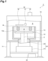
- the 3D manufacturing apparatus 1 illustrated in FIG. 1 is a so-called 3D printer.
- the 3D manufacturing apparatus 1 manufactures a 3D modeled object M from a powder material A.
- the 3D manufacturing apparatus 1 melts or sinters the powder material A by irradiating the powder material A with an energy beam.
- the 3D modeled object M is modeled.
- the 3D manufacturing apparatus 1 adopts a powder bed method. In the powder bed method, the spread powder material A is irradiated with an electron beam for modeling.
- the powder material A is metal powder.
- the powder material A is, for example, titanium-based metal powder, inconel powder, aluminum powder, etc.
- the powder material A is not limited to the metal powder.
- the powder material A may be, for example, resin powder.
- the powder material A may be powder containing carbon fibers such as carbon fiber reinforced plastics (CFRP).
- CFRP carbon fiber reinforced plastics
- the powder material A may be powder containing a resin.
- the powder material A may be other electrically conductive powder. It should be noted that the powder material A in the present disclosure is not limited to the electrically conductive powder. For example, when a laser is used as the energy beam, the powder material A does not have to be electrically conductive.
- the 3D manufacturing apparatus 1 includes a housing 10, a drive unit 20, a processing unit 30, and a controller 40.
- the housing 10 is supported by a plurality of columns 11.
- the housing 10 is a chamber that forms a modeling space S.
- the modeling space S accommodates the powder material A.
- the modeling space S is a space for processing the powder material A by the processing unit 30.
- the modeling space S can be depressurized and can be kept airtight.
- the table 12 and a modeling tank 13 accommodating the table 12 are disposed.
- the table 12 is a processing table on which a modeling process is performed.
- a shape of the table 12 is, for example, a disc.
- the powder material A which is a raw material of the modeled object M, is disposed on a main surface 12a of the table 12.
- the main surface 12a of the table 12 is a modeling surface or an upper surface.
- the table 12 is rotatable with respect to the housing 10.
- the rotation axis C of the table 12 overlaps with a central axis of the housing 10.
- the rotation axis C may be along a downward direction. In other words, the rotation axis C may be along the vertical direction.
- the drive unit 20 is connected to the table 12.
- the drive unit 20 implements various operations required for modeling.
- the drive unit 20 has, for example, a rotary drive unit 21 and a linear drive unit 22.
- the rotary drive unit 21 rotates the table 12 in the circumferential direction around the rotation axis C.
- the table 12 is coupled to an upper end of the rotary drive unit 21.
- a drive source such as an electric motor is attached to a lower end of the rotary drive unit 21.
- the rotary drive unit 21 raises and lowers the table 12 relative to the modeling tank 13. This raising and lowering is along the rotation axis C of the rotary drive unit 21. Therefore, the table 12 is rotated around the rotation axis C and linearly moved along the rotation axis C by the drive unit 20.
- the drive unit 20 may be any mechanism that can rotate and raise and lower the table 12, and is not limited to the mechanism described above.
- the processing unit 30 processes the powder material A to obtain the modeled object M.
- Processes for the powder material A include, for example, a supply process of the powder material A, a preheat process (preliminary heat process) of the powder material A, and a modeling process of the powder material A.
- the processing unit 30 is disposed above the table 12.
- the processing unit 30 faces the main surface 12a of the table 12.
- the processing unit 30 includes, for example, a feeder 31 that performs the supply process of the powder material A, a heater 32 that performs the preheat process of the powder material A, and a beam source 33 that performs the modeling process of the powder material A.
- the feeder 31, the heater 32, and the beam source 33 are disposed along the rotation direction R of the table 12.
- the feeder 31 is a supply unit that supplies the powder material A onto the main surface 12a of the table 12.
- the feeder 31 has a raw material tank and a leveling portion (not illustrated).
- the raw material tank stores the powder material A.
- the raw material tank supplies the powder material A onto the main surface 12a of the table 12.
- the leveling portion levels the surface of the powder material A on the table 12.
- the feeder 31 may have a roller portion, a rod-shaped member, a brush portion, etc. instead of the leveling portion.
- the heater 32 is a heating unit that preheats the powder material A supplied onto the main surface 12a of the table 12.
- the heater 32 preheats the powder material A before being irradiated with the electron beam.
- the heater 32 is disposed above the table 12.
- the heater 32 raises the temperature of the powder material A by radiant heat.
- an infrared heater may be used as the heater 32.
- the heater 32 may perform heating using another method.
- the beam source 33 emits the electron beam.
- the beam source 33 is an irradiation unit that irradiates the powder material A with the electron beam.
- an electron gun is used as the beam source 33.
- the beam source 33 generates the electron beam according to a potential difference generated between a cathode and an anode.
- the beam source 33 converges the electron beam by adjusting an electric field.
- the beam source 33 irradiates a desired position with the electron beam.
- the process of supplying the powder material A onto the main surface 12a of the table 12, the preliminary heat process of the powder material A, and the modeling process by beam irradiation can be performed in parallel. That is, supply of the powder material A at the position of the feeder 31, preheating of the powder material A at the position of the heater 32, and beam irradiation at the position of the beam source 33 are performed at the same timing. As a result, the modeled object M is modeled.
- the modeling time of the modeled object M can be shortened when compared to the case where supply of the powder material A, preheating of the powder material A, and beam irradiation are sequentially performed. In particular, it is effective when modeling a large modeled object M.
- the controller 40 illustrated in FIG. 1 controls the entire 3D manufacturing apparatus 1.
- the controller 40 includes, for example, a CPU that executes a program, a storage unit such as a ROM and a RAM, an input/output unit, and a driver.
- a plurality of functions of the controller 40 is implemented by operating the input/output unit under the control of the CPU and reading and writing data to and from the storage unit.
- a form and an arrangement location of the controller 40 are not particularly limited.
- the controller 40 is electrically connected to the drive unit 20 and the processing unit 30.
- the controller 40 performs rotation control and raising/lowering control on the table 12, operation control on the feeder 31, operation control on the heater 32, operation control on the beam source 33, etc.
- the controller 40 is electrically connected to the rotary drive unit 21 of the drive unit 20.
- the controller 40 outputs a control signal to the rotary drive unit 21 to control rotation of the table 12 through the operation of the rotary drive unit 21.
- the controller 40 operates the rotary drive unit 21.
- the table 12 rotates about the rotation axis C in the rotation direction R.
- the rotation speed of the table 12 is adjusted by a rotation speed adjusting unit 44, which will be described later.
- the controller 40 is electrically connected to the linear drive unit 22 of the drive unit 20.
- the controller 40 outputs a control signal to the linear drive unit 22.
- raising and lowering of the table 12 are controlled through the operation of the linear drive unit 22.
- the controller 40 raises and lowers the table 12 by operating the linear drive unit 22.
- the controller 40 disposes the table 12 at a position in an upper part of the modeling tank 13 at an initial stage of modeling.
- the controller 40 lowers the table 12 as the modeling of the modeled object M progresses.
- a lowering speed of the table 12 may be determined according to, for example, the rotation speed of the table 12.
- the controller 40 is electrically connected to the feeder 31 of the processing unit 30.
- the controller 40 outputs a control signal to the feeder 31.
- supply of the powder material A is controlled.
- the controller 40 operates the feeder 31.
- the powder material A is supplied onto the main surface 12a of the table 12.
- a surface layer of the powder material A on the table 12 is spread as the table 12 rotates.
- the controller 40 is electrically connected to the heater 32 of the processing unit 30.
- the controller 40 outputs a control signal to the heater 32.
- preheating of the powder material A is controlled.
- the controller 40 operates the heater 32.
- the powder material A on the main surface 12a of the table 12 is heated, so that the powder material A is preheated.
- the amount of heat given to the powder material A may be set according to the quality and type of the powder material A, the rotation speed of the table 12, etc.
- the controller 40 is electrically connected to the beam source 33 of the processing unit 30.
- the controller 40 outputs a control signal to the beam source 33.
- emission of the electron beam is controlled.
- the controller 40 operates the beam source 33.
- an electron beam is generated, so that a predetermined position of the powder material A is irradiated with the electron beam.
- the position irradiated with the electron beam is a region where the modeled object M needs to be modeled.
- a preset irradiation position is irradiated with the electron beam.
- the irradiation position is set by an irradiation position setting unit 43, which will be described later.
- the controller 40 includes a data acquisition unit 41, a region setting unit 42, an irradiation position setting unit 43, and a rotation speed adjusting unit 44.
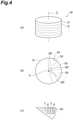
- the data acquisition unit 41 acquires slice data D of a cross section of the modeled object M.
- the cross section of the modeled object M intersects the rotation axis C in the modeled object M.
- the cross section of the modeled object M is orthogonal to the rotation axis C in the modeled object M. That is, the cross section of the modeled object M is a horizontal cross section.
- the data acquisition unit 41 acquires the slice data D of the modeled object M by using 3D computer-aided design (CAD) data of the modeled object M.
- CAD computer-aided design
- the data acquisition unit 41 acquires a plurality of pieces of slice data D according to vertical positions of the modeled object M.
- the slice data D for one layer corresponds to the powder material A for one layer.
- the region setting unit 42 sets an irradiation region 45 irradiated with the electron beam on the main surface 12a of the table 12.
- a horizontal cross section of the modeled object M included in the slice data D for one layer is illustrated in a direction in which the rotation axis C extends.
- the irradiation region 45 is the entire region that can be irradiated with the electron beam on the main surface 12a of the table 12.
- the irradiation region 45 corresponds to the horizontal cross section of the modeled object M included in the slice data D.
- the region setting unit 42 sets the irradiation region 45 for a plurality of pieces of slice data D.
- the irradiation region 45 is illustrated as a circular region centered on the rotation axis C.
- the region setting unit 42 divides the irradiation region 45 into a plurality of divided regions 50 in the circumferential direction centered on the rotation axis C.
- the shape of the plurality of divided regions 50 is a fan shape centered on the rotation axis C.
- central angles ⁇ of the divided regions 50 are mutually the same values.
- Each of the central angles ⁇ of the plurality of divided regions 50 is smaller than, for example, half of a maximum central angle ⁇ F of the divided regions 50 that fits in a modeling area F illustrated in FIG. 5 .
- the modeling area F is, for example, a circular region.
- the beam source 33 can irradiate the modeling area F with an electron beam.
- the central angle ⁇ F of the divided regions 50 that fits in the modeling area F is 60 degrees
- the central angle ⁇ of the divided regions 50 is smaller than 30 degrees.
- the irradiation position setting unit 43 sets an irradiation position of the electron beam for each of the divided regions 50.
- the irradiation position setting unit 43 sets the irradiation position of the electron beam as irradiation points P as illustrated in FIG. 4(c) .
- the irradiation points P are disposed at predetermined intervals along trajectory data T set for each of the divided regions 50.
- the irradiation position setting unit 43 generates data of a trajectory arranged along a certain direction as the trajectory data T.
- the irradiation position of the electron beam is a target for irradiating the electron beam.
- the irradiation position may be set according to an actual irradiation position.
- the irradiation position may be set as a command position for electron beam irradiation control.
- FIG. 4(c) illustrates the irradiation position set as the irradiation points P along the trajectory data T.
- data of the irradiation position includes the trajectory data T and a point data group. That is, in FIG. 4(c) , the irradiation points P are set at predetermined intervals on the trajectory data T. These irradiation points P are the irradiation position of the electron beam.
- the trajectory data T and the irradiation points P on the trajectory data T indicate the irradiation position within the divided regions 50. It should be noted that setting of the irradiation position with respect to the divided regions 50 is not limited to such a setting.
- setting of the irradiation position with respect to the divided regions 50 is not limited to setting of the trajectory data T and the point data group.
- the irradiation position may be set in another setting mode as long as a desired position can be irradiated with the electron beam with respect to the divided regions 50.
- one irradiation point P may be set for one piece of trajectory data T.
- only the trajectory data T may be set. In this case, the electron beam is irradiated to perform scan along the trajectory data T.
- the rotation speed adjusting unit 44 adjusts the rotation speed of the table 12 for each of the divided regions 50. That is, the rotation speed adjusting unit 44 sets the rotation speed of the table 12 for each of the divided regions 50. A specific method of setting the rotation speed by the rotation speed adjusting unit 44 will be described below with reference to FIGS. 6 and 7 .
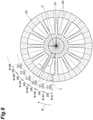
- FIG. 6 is a diagram illustrating the divided regions 50 in detail.
- the modeled object M is illustrated as a wheel using the rotation axis C extending in the vertical direction as a central axis.
- the irradiation region 45 corresponds to a cross-sectional shape when the wheel is cut in a horizontal plane.
- the irradiation region 45 has a double annular portion 60 and a plurality of linear portions 61.
- the double annular portion 60 is centered on the rotation axis C.
- the plurality of linear portions 61 connects a plurality of annular portions of the double annular portion 60 in a radial direction.
- the plurality of linear portions 61 is arranged at equal intervals in the circumferential direction.
- the plurality of divided regions 50 is obtained by dividing the irradiation region 45 in the circumferential direction.
- the plurality of divided regions 50 includes a plurality of first divided regions 51 and a plurality of second divided regions 52.
- the plurality of first divided regions 51 and the plurality of second divided regions 52 are arranged at different positions in the circumferential direction.
- the second divided regions 52 include the linear portions 61.
- An area of each of the second divided regions 52 is larger than an area of each of the first divided regions 51.
- the first divided regions 51 include the double annular portion 60 other than the linear portions 61.
- the area of each of the first divided regions 51 is smaller than the area of each of the second divided regions 52.
- the double annular portion 60 is separately disposed in the first divided regions 51.
- the area of the first divided regions 51 is a total area of the separated double annular portion 60.
- the respective first divided regions 51 and second divided regions 52 may be collectively referred to as "divided regions 50".
- the positions of the divided regions 50 in the circumferential direction is defined by an angle ⁇ centered on the rotation axis C.
- the angle ⁇ is set with reference to a reference line L.
- the reference line L is a straight line orthogonal to (or intersecting with) the rotation axis C in the irradiation region 45.
- the reference line L is set at a position overlapping with one of dividing lines of the divided regions 50.
- the dividing lines are broken lines in FIG. 6 .
- the dividing lines of the divided regions 50 are straight lines extending in the radial direction from the rotation axis C.
- the rotation angle indicates a difference between two dividing lines adjacent to each other in the circumferential direction.
- the rotation angle is a central angle ⁇ of the divided region 50. That is, the central angle ⁇ is defined by two dividing lines of the divided region 50.
- the central angle ⁇ may be defined as a division angle that divides the irradiation region 45 into the divided regions 50 in the circumferential direction.
- the central angles ⁇ of the plurality of divided regions 50 are mutually the same values. Therefore, a first central angle ⁇ of the first divided region 51 is the same as a second central angle ⁇ of the second divided region 52.
- a length r of the divided region 50 in the radial direction is a value obtained by summing lengths of only portions where the divided region 50 exists, not including a portion where the divided region 50 does not exist at a certain angle ⁇ . Therefore, as illustrated in FIG. 6 , the length r of the first divided region 51 is a sum of only lengths of the plurality of annular portions of the double annular portion 60. On the other hand, the length r of the second divided region 52 is a sum of a length of the linear portion 61 and lengths of the plurality of annular portions of the double annular portion 60 at an angle ⁇ indicating the position of the linear portion 61.
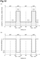
- a horizontal axis represents the angle ⁇ centered on the rotation axis C.
- a vertical axis indicates the length r of the divided region 50 in the radial direction centered on the rotation axis C.
- the area of the divided region 50 is the product of the central angle ⁇ of the divided region 50 and the length r of the divided region 50.
- the first central angle ⁇ of the first divided region 51 and the second central angle ⁇ of the second divided region 52 are the same as each other.
- a horizontal axis represents the angle ⁇ .
- a vertical axis represents the rotation speed of the table 12.
- the rotation speed adjusting unit 44 sets the rotation speed of the table 12 for each of the divided regions 50. Specifically, the rotation speed adjusting unit 44 sets a rotation speed ⁇ 2 of the table 12 during a period of irradiating the second divided region 52 with the electron beam. On the other hand, the rotation speed adjusting unit 44 sets a rotation speed ⁇ 1 of the table 12 to be faster than the rotation speed ⁇ 2 during a period of irradiating the first divided region 51 with the electron beam.
- the rotation speed of the table 12 is determined according to the area per unit central angle of the divided region 50. As the area per unit central angle of the divided region 50 increases, a time required to irradiate the area per unit central angle of the divided region 50 with the electron beam increases. The time required to irradiate the area per unit central angle of the divided region 50 with the electron beam is referred to as "unit irradiation time". On the other hand, as the area per unit central angle of the divided region 50 decreases, the unit irradiation time decreases. When the unit irradiation time is long, it is necessary to slow down the rotation speed of the table 12 in order to complete irradiation of the electron beam to all the portions of the divided region 50.
- the rotation speed of the table 12 can be increased for the divided region 50 having a small area per unit central angle.
- a relationship between the area per unit central angle and the rotation speed is not particularly limited as long as the above relationship is followed.
- the area per unit central angle of the first divided region 51 is 1/2 of the area per unit central angle of the second divided region 52.
- the rotation speed of the table 12 in the first divided region 51 may be twice the rotation speed of the table 12 in the second divided region 52.
- the area per unit central angle of the first divided region 51 is smaller than the area per unit central angle of the second divided region 52. Therefore, the unit irradiation time of the first divided region 51 is shorter than the unit irradiation time of the second divided region 52. Therefore, the rotation speed ⁇ 1 in the period of irradiating the first divided region 51 with the electron beam is faster than the rotation speed ⁇ 2 in the period of irradiating the second divided region 52 with the electron beam.
- the 3D manufacturing apparatus 1 of the present disclosure changes the rotation speed of the table 12 according to the area per unit central angle of the divided region 50.
- the plurality of divided regions 50 include the first divided regions 51 and the second divided regions 52.
- the plurality of divided regions 50 may have other divided regions in addition to the first divided regions 51 and the second divided regions 52. In this case, any two divided regions may be selected from these divided regions to define one of the divided regions whose area per unit central angle is small as the first divided region and define the other one of the divided regions whose area per unit central angle is large as the second divided region.
- the controller 40 executes a data reading process.
- the controller 40 reads 3D CAD data of the modeled object M.
- the data acquisition unit 41 acquires slice data D from the 3D CAD data (see FIG. 4(a) ). In this instance, the data acquisition unit 41 acquires a plurality of pieces of slice data D according to a vertical position of the modeled object M.
- the region setting unit 42 sets the irradiation region 45 to be irradiated with the electron beam on the main surface 12a of the table 12 for an n-th layer of the modeled object M (see FIG. 4(b) ).
- n in the n-th layer is a natural number.
- the region setting unit 42 divides the irradiation region 45 into the plurality of divided regions 50 in the circumferential direction centered on the rotation axis C.
- the central angles ⁇ at which the irradiation region 45 is divided into the divided regions 50 in the circumferential direction are set to, for example, the same values.
- the irradiation position setting unit 43 sets the irradiation position of the electron beam for each of the divided regions 50.
- the irradiation position setting unit 43 sets irradiation positions of the electron beam as irradiation points P (see FIG. 4(c) ).
- the irradiation points P are arranged at predetermined intervals along the trajectory data T set for each of the divided regions 50.
- the irradiation position setting unit 43 generates data of a trajectory arranged along a certain direction as the trajectory data T.
- the divided regions 50 move as the table 12 rotates. Therefore, the irradiation position setting unit 43 may correct the trajectory data T in order to irradiate the electron beam along the divided regions 50.
- the irradiation position setting unit 43 may use corrected trajectory data T as a curved trajectory.
- the rotation speed adjusting unit 44 determines the rotation speed of the table 12 for each of the divided regions 50.
- the area per unit central angle of the first divided region 51 is smaller than the area per unit central angle of the second divided region 52. Therefore, the unit irradiation time of the first divided region 51 is shorter than the unit irradiation time of the second divided region 52. Therefore, as illustrated in FIG. 7(b) , the rotation speed adjusting unit 44 sets the rotation speed ⁇ 1 in the period of irradiating the first divided region 51 with the electron beam to be faster than the rotation speed ⁇ 2 in the period of irradiating the second divided region 52 with the electron beam.
- the controller 40 controls the linear drive unit 22. As a result, the table 12 moves upward. As a result of moving upward, the table 12 is disposed in the upper part of the modeling tank 13. Further, the controller 40 controls the rotary drive unit 21. As a result, the table 12 rotates about the rotation axis C.
- the rotation speed of the table 12 is set by the rotation speed adjusting unit 44. As described above, the rotation speed adjusting unit 44 sets the rotation speed ⁇ 2 of the table 12 during the period of irradiating the second divided region 52 with the electron beam. In the period of irradiating the first divided region 51 with the electron beam, the rotation speed ⁇ 1 of the table 12 is set to be faster than the rotation speed ⁇ 2.
- the controller 40 controls the feeder 31.
- the powder material A is supplied onto the table 12.
- the powder material A on the table 12 is leveled by a recoater.
- the powder material A supplied by the feeder 31 moves as the table 12 rotates.
- the powder material A enters a region below the heater 32.
- the heater 32 preheats the powder material A disposed below the heater 32.
- the powder material A is heated while moving as the table 12 rotates.
- the powder material A preheated by the heater 32 moves as the table 12 rotates. As a result, the powder material A approaches the beam source 33 in the circumferential direction of the table 12.
- the controller 40 controls the beam source 33.
- the powder material A existing in the irradiation range of the beam source 33 is irradiated with the electron beam.
- the beam source 33 irradiates the electron beam for each of the divided regions 50 existing within the irradiation range of the beam source 33.
- the divided regions 50 rotate around the rotation axis C as the table 12 rotates.
- the powder material A on the plurality of divided regions 50 is sequentially irradiated with the electron beam.
- the modeled object M is modeled for each of the divided regions 50.
- a start position Pa for modeling in the divided regions 50 may be set as illustrated in FIG. 5 .
- the start position Pa is a fixed position corresponding to an installation position of the beam source 33.
- the start position Pa is a position when the entire one divided region 50 fits within the modeling area F. That is, when the entire one divided region 50 enters the modeling area F, the beam source 33 may start modeling the divided region 50.
- the table 12 descends as the modeling of the modeled object M progresses. That is, the controller 40 controls the linear drive unit 22. As a result, the table 12 descends along the rotation axis C. The descent of the table 12 may be synchronized with the rotation of the table 12. The descent of the table 12 does not have to be perfectly synchronized with the rotation of the table 12. When modeling for all the layers is completed, the modeling of the modeled object M is completed.
- the 3D manufacturing apparatus 1 While the table 12 rotates in the rotation direction R about the rotation axis C, the powder material A on the main surface 12a of the table 12 is sequentially irradiated with an electron beam for each of the divided regions 50.
- the area per unit central angle of the first divided region 51 is smaller than the area per unit central angle of the second divided region 52. Therefore, the unit irradiation time of the first divided region 51 is shorter than the unit irradiation time of the second divided region 52.
- the rotation speed of the table 12 when the rotation speed of the table 12 is set to a constant value based on a time required for the electron beam to the second divided region 52, a waiting time occurs after irradiation of the electron beam to the first divided region 51 is completed before irradiation of the electron beam to the first divided region 51 or the second divided region 52 is started.
- the rotation speed ⁇ 1 of the table 12 during the period of irradiating the first divided region 51 with the electron beam is faster than the rotation speed ⁇ 2 of the table 12 during the period of irradiating the second divided region 52 with the electron beam. In this way, by increasing the rotation speed ⁇ 1 of the table 12 when irradiating the first divided region 51 with the electron beam, the above-mentioned waiting time can be reduced. Therefore, the modeling time of the modeled object M can be shortened.
- the 3D manufacturing apparatus 1 of the present disclosure has been described as described above, the 3D manufacturing apparatus 1 of the present disclosure is not limited to the above description.
- the 3D manufacturing apparatus 1 of the present disclosure can take various modifications within a range that does not deviate from the spirit and scope of the claims.
- FIG. 8 illustrates a configuration of a controller 40A of a 3D manufacturing apparatus according to a first modification.
- a region setting unit 42A of the controller 40A of this modification includes a central angle adjusting unit 42a.
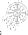
- the central angle adjusting unit 42a adjusts central angles of a plurality of divided regions 50A. Specifically, as illustrated in FIG. 9 , the central angle adjusting unit 42a sets a first central angle ⁇ 1 of a first divided region 511 and a second central angle ⁇ 2 of a second divided region 512 to different values.
- the first divided region 511 corresponds to the first divided region 51 (see FIG. 6 ) before adjustment by the central angle adjusting unit 42a.
- the second divided region 512 corresponds to the second divided region 52 (see FIG. 6 ) before adjustment by the central angle adjusting unit 42a.
- the central angle adjusting unit 42a performs setting so that the first central angle ⁇ 1 of the first divided region 511 after adjustment becomes larger than the first central angle ⁇ of the first divided region 51 before adjustment. Further, the central angle adjusting unit 42a performs setting so that the second central angle ⁇ 2 of the second divided region 512 after adjustment becomes smaller than the second central angle ⁇ of the second divided region 52 before adjustment.
- the second central angle ⁇ 2 of the second divided region 512 is set so that the area of the double annular portion 60 other than the linear portion 61 in the second divided region 52 is further reduced.
- the first central angle ⁇ 1 of the first divided region 511 is set to include two first divided regions 51 adjacent to each other.
- the first central angle ⁇ 1 of the first divided region 511 is set to be larger than the second central angle ⁇ 2 of the second divided region 512.
- a horizontal axis represents the angle ⁇ centered on the rotation axis C.
- a vertical axis represents a length r of an irradiation region in the radial direction centered on the rotation axis C.
- a radial length r of the first divided region 511 is the same as a radial length r of the first divided region 51. Therefore, the area per unit central angle of the first divided region 511 is the same as the area per unit central angle of the first divided region 51. Therefore, the unit irradiation time of the first divided region 511 is the same as the unit irradiation time of the first divided region 51.
- the total area of the second divided region 512 becomes smaller than the total area of the second divided region 52 before adjustment by a decreased amount of the second central angle ⁇ 2 of the second divided region 512.
- a horizontal axis represents the angle ⁇ .
- a vertical axis represents the rotation speed of the table 12.
- dividing lines of the first divided region 51 and the second divided region 52 before adjustment are indicated by alternate long and short dash lines.
- the rotation speed ⁇ 2 of the table 12 during the period of irradiating the second divided region 52 with the electron beam before adjustment is indicted by a chain line.
- the rotation speed ⁇ 1 of the table 12 is set during the period of irradiating the first divided region 511 with the electron beam.
- the rotation speed ⁇ 3 of the table 12 is set during the period of irradiating the second divided region 512 with the electron beam.
- the unit irradiation time of the second divided region 512 is slightly longer than the unit irradiation time of the second divided region 52. Therefore, the rotation speed ⁇ 3 is slightly slower than the rotation speed ⁇ 2.
- the first central angle ⁇ 1 of the first divided region 511 is increased by a decreased amount of the second central angle ⁇ 2 of the second divided region 512. Therefore, a proportion of the second divided region 512 in the irradiation region 45 becomes small. On the other hand, a proportion of the first divided region 511 in the irradiation region 45 becomes large. In this way, by increasing the proportion of the first divided region 51 in which the rotation speed ⁇ 1 of the table 12 is high, a time required for the table 12 to make one rotation can be shortened. That is, it is possible to modulate the area per unit central angle of the first divided region 511 and the area per unit central angle of the second divided region 512.
- the controller 40 of the embodiment causes a section from the angle ⁇ 2 to the angle ⁇ 11 illustrated in FIG. 10 to be included in a section which is the rotation speed ⁇ 2. That is, a rotation speed of the section from the angle ⁇ 2 to the angle ⁇ 11 in which modeling can be originally performed at the rotation speed ⁇ 1 is the rotation speed ⁇ 2, which is slower than the rotation speed ⁇ 1.
- the controller 40A of this modification causes the section from the angle ⁇ 2 to the angle ⁇ 11 to be included in the first divided region 511 by adjusting the central angle.
- the region setting unit 42A includes the central angle adjusting unit 42a.
- the region setting unit 42A does not have to include the central angle adjusting unit 42a.
- an external device provided outside the 3D manufacturing apparatus may include the central angle adjusting unit 42a.
- Data acquired by the data acquisition unit 41 from the external device may include data related to the first divided region 511 and data related to the second divided region 512.
- the first central angle ⁇ of the first divided region 511 is increased.
- the first central angle ⁇ 1 of the first divided region 511 should not be larger than half of the maximum central angle ⁇ F of the first divided region 511 that fits within the modeling area F (see FIG. 5 ).
- the first central angle ⁇ 1 of the first divided region 511 is limited to a certain size. Even when the first central angle ⁇ 1 of the first divided region 511 is limited in this way, the molding time of the modeled object M is further shortened by adjusting the rotation speed ⁇ 1 during the period of irradiating the first divided region 511 with the electron beam.
- FIG. 11 illustrates a configuration of a controller 40B of a 3D manufacturing apparatus according to a second modification.
- a region setting unit 42B of the controller 40B of this modification includes a phase difference adjusting unit 42b.
- the phase difference adjusting unit 42b adjusts phase differences of a plurality of divided regions 50B.
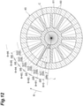
- a phase difference of a divided region 50B is a rotation angle indicating a difference in the circumferential direction between a reference line L and a dividing line indicating a boundary of the divided region 50B in the circumferential direction.
- the reference line L is set at a position overlapping the dividing line of the first divided region 51 before adjustment (see FIG. 6 ) by the phase difference adjusting unit 42b.
- the phase difference adjusting unit 42b sets a phase difference of the divided region 50B after adjustment and a phase difference of the divided region 50B before adjustment to different values.
- the phase difference adjusting unit 42b performs adjustment so that the phase difference of the divided region 50B after adjustment is larger than the phase difference of the divided region 50 before adjustment. Specifically, the phase difference adjusting unit 42b increases the phase difference of the divided region 50B after adjustment by a phase difference ⁇ p in the rotation direction R with respect to the phase difference of the divided region 50 before adjustment.
- the dividing line of the divided region 50B is located at a center of the linear portion 61 in the circumferential direction.
- Each of two divided regions 50B sharing the dividing line that bisects the linear portion 61 becomes the second divided region 522. Even after the phase difference is adjusted by the phase difference adjusting unit 42b, the divided region 50B not including the linear portion 61 becomes the first divided region 521.
- the second divided region 522 far from the reference line corresponds to the second divided region 52 before adjustment (see FIG. 6 ).
- the second divided region 522 near the reference line corresponds to the first divided region 51 before adjustment.
- the first divided region 521 corresponds to the first divided region 51 before adjustment.
- a horizontal axis represents the angle ⁇ centered on the rotation axis C.
- a vertical axis represents the length r of the irradiation region in the radial direction centered on the rotation axis C.
- the area per unit central angle of the second divided region 522 is smaller than the area per unit central angle of the second divided region 52 before adjustment. Therefore, the unit irradiation time of the second divided region 522 is shorter than the unit irradiation time of the second divided region 52.
- a horizontal axis represents the angle ⁇ .
- a vertical axis represents the rotation speed of the table 12.
- dividing lines of the first divided region 51 and the second divided region 52 before adjustment are indicated by two-dot chain lines.
- the rotation speed ⁇ 2 of the table 12 during the period of irradiating the second divided region 52 with the electron beam before adjustment is indicated by a chain line.
- the rotation speed ⁇ 1 of the table 12 is set during the period of irradiating the first divided region 511 with the electron beam.
- the rotation speed ⁇ 4 of the table 12 is set during the period of irradiating the second divided region 512 with the electron beam.
- the unit irradiation time of the second divided region 522 is shorter than the unit irradiation time of the second divided region 52. Therefore, the rotation speed ⁇ 4 in the period of irradiating the second divided region 522 with the electron beam is faster than the rotation speed ⁇ 2 in the period of irradiating the second divided region 52 with the electron beam.
- the area per unit central angle of the second divided region 522 can be reduced by adjusting the phase differences of the plurality of divided regions 50B using the phase difference adjusting unit 42b. Accordingly, the unit irradiation time of the second divided region 522 can be shortened. As a result, the rotation speed ⁇ 4 of the table 12 with respect to the second divided region 522 can be increased, so that the modeling time of the modeled object M can be further shortened.
- the controller 40B adjusts a phase difference so that a difference (ratio) between the area per unit central angle of the first divided region 521 and the area per unit central angle of the second divided region 522 becomes small.
- the area is related to the rotation speed. Therefore, as the difference in area becomes smaller, the difference in rotation speed becomes smaller. That is, the rotation speed ⁇ 4 becomes faster.
- the rotation speed ⁇ 4 can be made close to the rotation speed ⁇ 1. That is, as illustrated in FIG. 13(b) , a difference ⁇ 4 between the rotation speed ⁇ 4 and the rotation speed ⁇ 1 can be made smaller than a difference ⁇ 2 between the rotation speed ⁇ 2 and the rotation speed ⁇ 1. In this way, the rotation speeds ⁇ 1 and ⁇ 4 of the table 12 can be easily kept within a permissible range of the rotation speed of the table 12, so that stability of the rotation speed of the table 12 can be improved.
- the present disclosure can be modified in various other ways.
- the embodiment and the plurality of modifications may be combined with each other according to the required purpose and effect.
- the configuration of the 3D manufacturing apparatus 1 may be changed as appropriate.
- the controller 40 of the 3D manufacturing apparatus may include a data generation unit that generates the slice data D instead of the data acquisition unit 41 that acquires the slice data D.
- the 3D manufacturing apparatus may include a plurality of feeders, a plurality of heaters, and a plurality of beam sources.
- the 3D manufacturing apparatus may include two feeders, two heaters, and two beam sources.
- the powder material can be supplied, the powder material can be preheated, and beam irradiation can be performed on one side of a half of the table.
- the powder material can be supplied, the powder material can be preheated, and beam irradiation can be performed on the other side of the half of the table. Therefore, the modeled object can be modeled more efficiently.
- the 3D manufacturing apparatus may include three or more feeders, three or more heaters, and three or more beam sources.
- the 3D manufacturing apparatus models the modeled object M using the electron beam as an energy beam.
- the 3D manufacturing apparatus may model the modeled object using an energy beam other than the electron beam.
- the 3D manufacturing apparatus may irradiate an ion beam, a laser beam, ultraviolet rays, etc. to model the modeled object.
- the 3D manufacturing apparatus may model the modeled object using a method other than the powder bed method.
- 1 3D manufacturing apparatus, 12: table, 12a: main surface, 20: drive unit, 21: rotary drive unit, 22: linear drive unit, 30: processing unit, 31: feeder, 32: heater, 33: beam source (irradiation unit), 40, 40A, 40B: controller, 41: data acquisition unit, 42, 42A, 42B: region setting unit, 42a: central angle adjusting unit, 42b: phase difference adjusting unit, 43: irradiation position setting unit, 44: rotation speed adjusting unit, 45: irradiation region, 50, 50A, 50B: divided region, 51, 511, 521: first divided region, 52, 512, 522: second divided region, A: powder material, C: rotation axis, L: reference line, M: modeled object, R: rotation direction, ⁇ , ⁇ 1: first central angle, ⁇ , ⁇ 2: second central angle, ⁇ p: phase difference, ⁇ 1, ⁇ 2, ⁇ 3, ⁇ 4: rotation speed.
Landscapes
- Engineering & Computer Science (AREA)
- Chemical & Material Sciences (AREA)
- Materials Engineering (AREA)
- Manufacturing & Machinery (AREA)
- Physics & Mathematics (AREA)
- Optics & Photonics (AREA)
- Mechanical Engineering (AREA)
- Plasma & Fusion (AREA)
- Health & Medical Sciences (AREA)
- General Health & Medical Sciences (AREA)
- Toxicology (AREA)
- Powder Metallurgy (AREA)
Abstract
Description
- The present disclosure relates to a three-dimensional manufacturing apparatus.
-
Patent Literature 1 and Patent Literature 2 disclose a technology related to a three-dimensional modeling apparatus for modeling a modeled object. In the technology for modeling a modeled object disclosed inPatent Literature 1, an energy beam is irradiated onto a material applied to a rotating forming container. In the technology for modeling a modeled object disclosed in Patent Literature 2, a liquid is ejected from an inkjet in a printhead onto a material on a rotating table. The liquid is subjected to a printing process for curing. -
- Patent Literature 1:
Japanese Translation of PCT International Application Publication No. 2005-534543 - Patent Literature 2:
Japanese Unexamined Patent Publication No. 2016-74205 - For example, the three-dimensional modeling apparatus described in
Patent Literature 1 sequentially irradiates a plurality of regions along a rotation direction of a table with an energy beam while rotating the table which is the forming container. As a result, each layer of the modeled object is stacked. A rotation speed of the table is set based on a time required to irradiate the plurality of regions on the table with the energy beam. The rotation speed of the table is set to a constant value, for example. However, the area of a cross section of the layer of the modeled object may differ for each region. As a result, the time required for irradiating the energy beam changes for each region according to the difference in area. In this case, the rotation speed of the table does not correspond to the change in the time required for the irradiation. Therefore, a loss of modeling time occurs. - The present disclosure describes a three-dimensional manufacturing apparatus capable of shortening a modeling time.
- A three-dimensional manufacturing apparatus of the present disclosure models a three-dimensional modeled object by irradiating a powder material supplied onto a main surface of a table with an energy beam. The three-dimensional manufacturing apparatus includes a rotary drive unit that rotates the table about a rotation axis in a circumferential direction, a region setting unit that sets a plurality of divided regions obtained by dividing, in the circumferential direction, an irradiation region of the energy beam on the main surface of the table, the irradiation region corresponding to a cross section of the modeled object intersecting the rotation axis, an irradiation unit that faces the main surface of the table and irradiates the powder material with the energy beam for each of the divided regions, and a rotation speed adjusting unit that adjusts a rotation speed of the table. An area per unit central angle of a first divided region among the plurality of divided regions is smaller than an area per unit central angle of a second divided region among the plurality of divided regions. The rotation speed adjusting unit performs adjustment so that a rotation speed of the table during a period of irradiating the first divided region with the energy beam becomes faster than a rotation speed of the table during a period of irradiating the second divided region with the energy beam.
- In the three-dimensional manufacturing apparatus, while the table rotates in the circumferential direction about the rotation axis, the powder material on the main surface of the table is sequentially irradiated with an energy beam for each of the divided regions. Here, the area per unit central angle of the first divided region is smaller than the area per unit central angle of the second divided region. Therefore, a time required to irradiate the area per unit central angle of the first divided region with the energy beam is shorter than a time required to irradiate the area per unit central angle of the second divided region with the energy beam. As a result, when the rotation speed of the table is set to a constant value based on a time required for the energy beam to the second divided region, a waiting time occurs after irradiation of the energy beam to the first divided region is completed before irradiation of the energy beam to the subsequent divided region is started. On the other hand, in the three-dimensional manufacturing apparatus, the rotation speed of the table during the period of irradiating the first divided region with the energy beam is adjusted to be faster than the rotation speed of the table during the period of irradiating the second divided region with the energy beam. In this way, by increasing the rotation speed of the table when irradiating the first divided region with the energy beam, the above-mentioned waiting time can be reduced. Therefore, the modeling time of the modeled object can be shortened.
- In some aspects, a first central angle of the first divided region and a second central angle of the second divided region may be different values. For example, the first central angle of the first divided region is increased, and the second central angle of the second divided region is decreased. As a result, it is possible to increase a proportion of the first divided region in the irradiation region, and to decrease a proportion of the second divided region in the irradiation region. In this way, it is possible to shorten a time required for the table to make one rotation by increasing the proportion of the first divided region in which the rotation speed of the table is high. Therefore, according to the configuration, it is possible to further shorten the modeling time of the modeled object.
- In some aspects, the region setting unit may include a phase difference adjusting unit that adjusts a phase difference which is a rotation angle indicating a difference between a reference line intersecting the rotation axis on the main surface of the table and a dividing line defining a central angle of the second divided region in the circumferential direction. The phase difference adjusting unit may set the phase difference of the second divided region after adjustment to a different value from a value of the phase difference of the second divided region before adjustment, and a central angle of the second divided region may be the same value before and after adjustment by the phase difference adjusting unit. In this way, it is possible to decrease the area per unit central angle of the second divided region by adjusting the phase difference of the second divided region. Accordingly, it is possible to shorten a time required for the energy beam to the area per unit central angle of the second divided region. As a result, it is possible to increase the rotation speed of the table during the period of irradiating the second divided region with the energy beam, and thus it is possible to further shorten the modeling time of the modeled object.
- According to some aspects of the present disclosure, a three-dimensional manufacturing apparatus capable of shortening a modeling time is provided.
-
-
FIG. 1 is a cross-sectional view illustrating a three-dimensional manufacturing apparatus according to an embodiment. -
FIG. 2 is a configuration diagram illustrating a processing unit included in the three-dimensional manufacturing apparatus ofFIG. 1 . -
FIG. 3 is a block diagram illustrating a controller included in the three-dimensional manufacturing apparatus ofFIG. 1 . -
FIGS. 4(a), 4(b), and 4(c) are diagrams for description of a processing procedure in the controller ofFIG. 3 . -
FIG. 5 is a diagram for description of limitation of a central angle of a divided region set by the controller ofFIG. 3 . -
FIG. 6 is a diagram for description of an area of a divided region set by the controller ofFIG. 3 . -
FIG. 7(a) is a graph for description of the area of a divided region ofFIG. 6 , andFIG. 7(b) is a graph for description of a relationship between the area of the divided region ofFIG. 6 and a rotation speed of a table. -
FIG. 8 is a block diagram illustrating a configuration of a controller included in a three-dimensional manufacturing apparatus according to a first modification. -
FIG. 9 is a diagram for description of an area of a divided region set by the controller ofFIG. 8 . -
FIG. 10(a) is a graph for description of the area of the divided region ofFIG. 9 , andFIG. 10(b) is a graph for description of a relationship between the area of the divided region ofFIG. 9 and a rotation speed of a table. -
FIG. 11 is a block diagram illustrating a configuration of a controller included in a three-dimensional manufacturing apparatus according to a second modification. -
FIG. 12 is a diagram for description of an area of a divided region set by the controller ofFIG. 11 . -
FIG. 13(a) is a graph for description of the area of the divided region ofFIG. 12 , andFIG. 13(b) is a graph for description of a relationship between the area of the divided region ofFIG. 12 and a rotation speed of a table. - Hereinafter, a three-dimensional (3D)
manufacturing apparatus 1 of the present disclosure will be described with reference to the drawings. It should be noted that in the description of the drawings, the same elements are designated by the same reference symbols. Further, a duplicate description will be omitted. In the following description, the words "upper" and "lower" are used with reference to a state in which a rotation axis C (seeFIG. 1 ) of a table 12, which will be described later, is along a vertical direction. The word "lower" refers to a ground side in the vertical direction in the state in which the rotation axis C is along the vertical direction. The word "upper" refers to an opposite side from a ground in the vertical direction in the state in which the rotation axis C is along the vertical direction. A "circumferential direction" refers to a direction along a ring centered on the rotation axis C of the table 12. The "circumferential direction" refers to a direction including a rotation direction R (seeFIG. 2 ) of the table 12. - The
3D manufacturing apparatus 1 illustrated inFIG. 1 is a so-called 3D printer. The3D manufacturing apparatus 1 manufactures a 3D modeled object M from a powder material A. For example, the3D manufacturing apparatus 1 melts or sinters the powder material A by irradiating the powder material A with an energy beam. As a result, the 3D modeled object M is modeled. The3D manufacturing apparatus 1 adopts a powder bed method. In the powder bed method, the spread powder material A is irradiated with an electron beam for modeling. - The powder material A is metal powder. The powder material A is, for example, titanium-based metal powder, inconel powder, aluminum powder, etc. The powder material A is not limited to the metal powder. The powder material A may be, for example, resin powder. The powder material A may be powder containing carbon fibers such as carbon fiber reinforced plastics (CFRP). The powder material A may be powder containing a resin. The powder material A may be other electrically conductive powder. It should be noted that the powder material A in the present disclosure is not limited to the electrically conductive powder. For example, when a laser is used as the energy beam, the powder material A does not have to be electrically conductive.
- The
3D manufacturing apparatus 1 includes ahousing 10, adrive unit 20, aprocessing unit 30, and acontroller 40. Thehousing 10 is supported by a plurality ofcolumns 11. Thehousing 10 is a chamber that forms a modeling space S. The modeling space S accommodates the powder material A. The modeling space S is a space for processing the powder material A by theprocessing unit 30. The modeling space S can be depressurized and can be kept airtight. In the modeling space S, the table 12 and amodeling tank 13 accommodating the table 12 are disposed. The table 12 is a processing table on which a modeling process is performed. A shape of the table 12 is, for example, a disc. The powder material A, which is a raw material of the modeled object M, is disposed on amain surface 12a of the table 12. It can be considered that themain surface 12a of the table 12 is a modeling surface or an upper surface. The table 12 is rotatable with respect to thehousing 10. The rotation axis C of the table 12 overlaps with a central axis of thehousing 10. The rotation axis C may be along a downward direction. In other words, the rotation axis C may be along the vertical direction. - The
drive unit 20 is connected to the table 12. Thedrive unit 20 implements various operations required for modeling. Thedrive unit 20 has, for example, arotary drive unit 21 and alinear drive unit 22. Therotary drive unit 21 rotates the table 12 in the circumferential direction around the rotation axis C. For example, the table 12 is coupled to an upper end of therotary drive unit 21. A drive source such as an electric motor is attached to a lower end of therotary drive unit 21. Therotary drive unit 21 raises and lowers the table 12 relative to themodeling tank 13. This raising and lowering is along the rotation axis C of therotary drive unit 21. Therefore, the table 12 is rotated around the rotation axis C and linearly moved along the rotation axis C by thedrive unit 20. It should be noted that thedrive unit 20 may be any mechanism that can rotate and raise and lower the table 12, and is not limited to the mechanism described above. - The
processing unit 30 processes the powder material A to obtain the modeled object M. Processes for the powder material A include, for example, a supply process of the powder material A, a preheat process (preliminary heat process) of the powder material A, and a modeling process of the powder material A. Theprocessing unit 30 is disposed above the table 12. Theprocessing unit 30 faces themain surface 12a of the table 12. As illustrated inFIG. 2 , theprocessing unit 30 includes, for example, afeeder 31 that performs the supply process of the powder material A, aheater 32 that performs the preheat process of the powder material A, and abeam source 33 that performs the modeling process of the powder material A. Thefeeder 31, theheater 32, and thebeam source 33 are disposed along the rotation direction R of the table 12. - The
feeder 31 is a supply unit that supplies the powder material A onto themain surface 12a of the table 12. For example, thefeeder 31 has a raw material tank and a leveling portion (not illustrated). The raw material tank stores the powder material A. The raw material tank supplies the powder material A onto themain surface 12a of the table 12. The leveling portion levels the surface of the powder material A on the table 12. It should be noted that thefeeder 31 may have a roller portion, a rod-shaped member, a brush portion, etc. instead of the leveling portion. - The
heater 32 is a heating unit that preheats the powder material A supplied onto themain surface 12a of the table 12. Theheater 32 preheats the powder material A before being irradiated with the electron beam. For example, theheater 32 is disposed above the table 12. Theheater 32 raises the temperature of the powder material A by radiant heat. For example, an infrared heater may be used as theheater 32. Theheater 32 may perform heating using another method. - The
beam source 33 emits the electron beam. Thebeam source 33 is an irradiation unit that irradiates the powder material A with the electron beam. For example, an electron gun is used as thebeam source 33. Thebeam source 33 generates the electron beam according to a potential difference generated between a cathode and an anode. Thebeam source 33 converges the electron beam by adjusting an electric field. Thebeam source 33 irradiates a desired position with the electron beam. - According to the arrangement of the
feeder 31, theheater 32 and thebeam source 33 along the rotation direction R of the table 12 and the molding for rotating the table 12, the process of supplying the powder material A onto themain surface 12a of the table 12, the preliminary heat process of the powder material A, and the modeling process by beam irradiation can be performed in parallel. That is, supply of the powder material A at the position of thefeeder 31, preheating of the powder material A at the position of theheater 32, and beam irradiation at the position of thebeam source 33 are performed at the same timing. As a result, the modeled object M is modeled. Therefore, the modeling time of the modeled object M can be shortened when compared to the case where supply of the powder material A, preheating of the powder material A, and beam irradiation are sequentially performed. In particular, it is effective when modeling a large modeled object M. - The
controller 40 illustrated inFIG. 1 controls the entire3D manufacturing apparatus 1. Thecontroller 40 includes, for example, a CPU that executes a program, a storage unit such as a ROM and a RAM, an input/output unit, and a driver. A plurality of functions of thecontroller 40 is implemented by operating the input/output unit under the control of the CPU and reading and writing data to and from the storage unit. A form and an arrangement location of thecontroller 40 are not particularly limited. Thecontroller 40 is electrically connected to thedrive unit 20 and theprocessing unit 30. Thecontroller 40 performs rotation control and raising/lowering control on the table 12, operation control on thefeeder 31, operation control on theheater 32, operation control on thebeam source 33, etc. - As illustrated in
FIG. 3 , thecontroller 40 is electrically connected to therotary drive unit 21 of thedrive unit 20. Thecontroller 40 outputs a control signal to therotary drive unit 21 to control rotation of the table 12 through the operation of therotary drive unit 21. For example, thecontroller 40 operates therotary drive unit 21. As a result, the table 12 rotates about the rotation axis C in the rotation direction R. The rotation speed of the table 12 is adjusted by a rotationspeed adjusting unit 44, which will be described later. - The
controller 40 is electrically connected to thelinear drive unit 22 of thedrive unit 20. Thecontroller 40 outputs a control signal to thelinear drive unit 22. As a result, raising and lowering of the table 12 are controlled through the operation of thelinear drive unit 22. For example, thecontroller 40 raises and lowers the table 12 by operating thelinear drive unit 22. Specifically, thecontroller 40 disposes the table 12 at a position in an upper part of themodeling tank 13 at an initial stage of modeling. Then, thecontroller 40 lowers the table 12 as the modeling of the modeled object M progresses. A lowering speed of the table 12 may be determined according to, for example, the rotation speed of the table 12. - The
controller 40 is electrically connected to thefeeder 31 of theprocessing unit 30. Thecontroller 40 outputs a control signal to thefeeder 31. As a result, supply of the powder material A is controlled. For example, thecontroller 40 operates thefeeder 31. As a result, the powder material A is supplied onto themain surface 12a of the table 12. A surface layer of the powder material A on the table 12 is spread as the table 12 rotates. - The
controller 40 is electrically connected to theheater 32 of theprocessing unit 30. Thecontroller 40 outputs a control signal to theheater 32. As a result, preheating of the powder material A is controlled. For example, thecontroller 40 operates theheater 32. As a result, the powder material A on themain surface 12a of the table 12 is heated, so that the powder material A is preheated. The amount of heat given to the powder material A may be set according to the quality and type of the powder material A, the rotation speed of the table 12, etc. - The
controller 40 is electrically connected to thebeam source 33 of theprocessing unit 30. Thecontroller 40 outputs a control signal to thebeam source 33. As a result, emission of the electron beam is controlled. For example, thecontroller 40 operates thebeam source 33. As a result, an electron beam is generated, so that a predetermined position of the powder material A is irradiated with the electron beam. The position irradiated with the electron beam is a region where the modeled object M needs to be modeled. A preset irradiation position is irradiated with the electron beam. The irradiation position is set by an irradiationposition setting unit 43, which will be described later. - The
controller 40 includes adata acquisition unit 41, aregion setting unit 42, an irradiationposition setting unit 43, and a rotationspeed adjusting unit 44. As illustrated inFIG. 4(a) , thedata acquisition unit 41 acquires slice data D of a cross section of the modeled object M. The cross section of the modeled object M intersects the rotation axis C in the modeled object M. In the present disclosure, the cross section of the modeled object M is orthogonal to the rotation axis C in the modeled object M. That is, the cross section of the modeled object M is a horizontal cross section. Thedata acquisition unit 41 acquires the slice data D of the modeled object M by using 3D computer-aided design (CAD) data of the modeled object M. Even thoughFIG. 4(a) illustrates the case where the modeled object M is a cylindrical body, the modeled object M may have other shapes. Thedata acquisition unit 41 acquires a plurality of pieces of slice data D according to vertical positions of the modeled object M. The slice data D for one layer corresponds to the powder material A for one layer. - As illustrated in
FIG. 4(b) , theregion setting unit 42 sets anirradiation region 45 irradiated with the electron beam on themain surface 12a of the table 12. InFIG. 4(b) , a horizontal cross section of the modeled object M included in the slice data D for one layer is illustrated in a direction in which the rotation axis C extends. Theirradiation region 45 is the entire region that can be irradiated with the electron beam on themain surface 12a of the table 12. Theirradiation region 45 corresponds to the horizontal cross section of the modeled object M included in the slice data D. Theregion setting unit 42 sets theirradiation region 45 for a plurality of pieces of slice data D. In the example illustrated inFIG. 4(b) , theirradiation region 45 is illustrated as a circular region centered on the rotation axis C. - The
region setting unit 42 divides theirradiation region 45 into a plurality of dividedregions 50 in the circumferential direction centered on the rotation axis C. In the example illustrated inFIG. 4(b) , the shape of the plurality of dividedregions 50 is a fan shape centered on the rotation axis C. For example, central angles Δθ of the dividedregions 50 are mutually the same values. Each of the central angles Δθ of the plurality of dividedregions 50 is smaller than, for example, half of a maximum central angle ΔθF of the dividedregions 50 that fits in a modeling area F illustrated inFIG. 5 . - The modeling area F is, for example, a circular region. The
beam source 33 can irradiate the modeling area F with an electron beam. When the maximum central angle ΔθF of the dividedregions 50 that fits in the modeling area F is 60 degrees, the central angle Δθ of the dividedregions 50 is smaller than 30 degrees. By setting the central angle Δθ in this way, when the dividedregions 50 are in rotary motion due to rotation of the table 12, the modeling process on the dividedregions 50 can be completed while the dividedregions 50 pass through the modeling area F. In other words, it is possible to prevent the dividedregions 50 from passing through the modeling area F before the modeling process on the dividedregions 50 is completed. - The irradiation
position setting unit 43 sets an irradiation position of the electron beam for each of the dividedregions 50. The irradiationposition setting unit 43 sets the irradiation position of the electron beam as irradiation points P as illustrated inFIG. 4(c) . The irradiation points P are disposed at predetermined intervals along trajectory data T set for each of the dividedregions 50. For example, the irradiationposition setting unit 43 generates data of a trajectory arranged along a certain direction as the trajectory data T. The irradiation position of the electron beam is a target for irradiating the electron beam. The irradiation position may be set according to an actual irradiation position. The irradiation position may be set as a command position for electron beam irradiation control. -
FIG. 4(c) illustrates the irradiation position set as the irradiation points P along the trajectory data T. In the example ofFIG. 4(c) , data of the irradiation position includes the trajectory data T and a point data group. That is, inFIG. 4(c) , the irradiation points P are set at predetermined intervals on the trajectory data T. These irradiation points P are the irradiation position of the electron beam. The trajectory data T and the irradiation points P on the trajectory data T indicate the irradiation position within the dividedregions 50. It should be noted that setting of the irradiation position with respect to the dividedregions 50 is not limited to such a setting. That is, setting of the irradiation position with respect to the dividedregions 50 is not limited to setting of the trajectory data T and the point data group. The irradiation position may be set in another setting mode as long as a desired position can be irradiated with the electron beam with respect to the dividedregions 50. For example, as setting of the irradiation position, one irradiation point P may be set for one piece of trajectory data T. Alternatively, as setting of the irradiation position, only the trajectory data T may be set. In this case, the electron beam is irradiated to perform scan along the trajectory data T. - The rotation
speed adjusting unit 44 adjusts the rotation speed of the table 12 for each of the dividedregions 50. That is, the rotationspeed adjusting unit 44 sets the rotation speed of the table 12 for each of the dividedregions 50. A specific method of setting the rotation speed by the rotationspeed adjusting unit 44 will be described below with reference toFIGS. 6 and7 . -
FIG. 6 is a diagram illustrating the dividedregions 50 in detail. InFIG. 6 , the modeled object M is illustrated as a wheel using the rotation axis C extending in the vertical direction as a central axis. Theirradiation region 45 corresponds to a cross-sectional shape when the wheel is cut in a horizontal plane. For example, theirradiation region 45 has a doubleannular portion 60 and a plurality oflinear portions 61. The doubleannular portion 60 is centered on the rotation axis C. The plurality oflinear portions 61 connects a plurality of annular portions of the doubleannular portion 60 in a radial direction. For example, the plurality oflinear portions 61 is arranged at equal intervals in the circumferential direction. - The plurality of divided
regions 50 is obtained by dividing theirradiation region 45 in the circumferential direction. The plurality of dividedregions 50 includes a plurality of first dividedregions 51 and a plurality of second dividedregions 52. The plurality of first dividedregions 51 and the plurality of second dividedregions 52 are arranged at different positions in the circumferential direction. The second dividedregions 52 include thelinear portions 61. An area of each of the second dividedregions 52 is larger than an area of each of the first dividedregions 51. The first dividedregions 51 include the doubleannular portion 60 other than thelinear portions 61. The area of each of the first dividedregions 51 is smaller than the area of each of the second dividedregions 52. It should be noted that the doubleannular portion 60 is separately disposed in the first dividedregions 51. The area of the first dividedregions 51 is a total area of the separated doubleannular portion 60. In the following description, for convenience of description, "the respective first dividedregions 51 and second dividedregions 52" may be collectively referred to as "dividedregions 50". - As illustrated in
FIG. 6 , the positions of the dividedregions 50 in the circumferential direction is defined by an angle θ centered on the rotation axis C. The angle θ is set with reference to a reference line L. The reference line L is a straight line orthogonal to (or intersecting with) the rotation axis C in theirradiation region 45. In the example illustrated inFIG. 6 , the reference line L is set at a position overlapping with one of dividing lines of the dividedregions 50. The dividing lines are broken lines inFIG. 6 . The dividing lines of the dividedregions 50 are straight lines extending in the radial direction from the rotation axis C. The dividing lines indicate boundaries of the dividedregions 50 in the circumferential direction. Assuming that the position of the reference line L in the rotation direction R is set to θ = 0, the positions of the dividing lines of the plurality of dividedregions 50 in the rotation direction R are defined as θ = θ1, θ2, θ3, .... - The rotation angle indicates a difference between two dividing lines adjacent to each other in the circumferential direction. The rotation angle is a central angle Δθ of the divided
region 50. That is, the central angle Δθ is defined by two dividing lines of the dividedregion 50. The central angle Δθ may be defined as a division angle that divides theirradiation region 45 into the dividedregions 50 in the circumferential direction. As described above, for example, the central angles Δθ of the plurality of dividedregions 50 are mutually the same values. Therefore, a first central angle Δθ of the first dividedregion 51 is the same as a second central angle Δθ of the second dividedregion 52. - A length r of the divided
region 50 in the radial direction is a value obtained by summing lengths of only portions where the dividedregion 50 exists, not including a portion where the dividedregion 50 does not exist at a certain angle θ. Therefore, as illustrated inFIG. 6 , the length r of the first dividedregion 51 is a sum of only lengths of the plurality of annular portions of the doubleannular portion 60. On the other hand, the length r of the second dividedregion 52 is a sum of a length of thelinear portion 61 and lengths of the plurality of annular portions of the doubleannular portion 60 at an angle θ indicating the position of thelinear portion 61. - In
FIG. 7(a) , a horizontal axis represents the angle θ centered on the rotation axis C. A vertical axis indicates the length r of the dividedregion 50 in the radial direction centered on the rotation axis C. When the length r of the dividedregion 50 is defined as described above, the area of the dividedregion 50 is the product of the central angle Δθ of the dividedregion 50 and the length r of the dividedregion 50. In the present disclosure, as described above, the first central angle Δθ of the first dividedregion 51 and the second central angle Δθ of the second dividedregion 52 are the same as each other. On the other hand, as illustrated inFIG. 7(a) , for example, an average value of the length r of the first dividedregion 51 from the angle θ = 0 to the angle θ = θ1 is smaller than an average value of the length r of the second dividedregion 52 from the angle θ = θ2 to the angle θ = θ3. Therefore, the area per unit central angle of the first dividedregion 51 is smaller than the area per unit central angle of the second dividedregion 52. - In
FIG. 7(b) , a horizontal axis represents the angle θ. A vertical axis represents the rotation speed of the table 12. The rotationspeed adjusting unit 44 sets the rotation speed of the table 12 for each of the dividedregions 50. Specifically, the rotationspeed adjusting unit 44 sets a rotation speed ω2 of the table 12 during a period of irradiating the second dividedregion 52 with the electron beam. On the other hand, the rotationspeed adjusting unit 44 sets a rotation speed ω1 of the table 12 to be faster than the rotation speed ω2 during a period of irradiating the first dividedregion 51 with the electron beam. - The rotation speed of the table 12 is determined according to the area per unit central angle of the divided
region 50. As the area per unit central angle of the dividedregion 50 increases, a time required to irradiate the area per unit central angle of the dividedregion 50 with the electron beam increases. The time required to irradiate the area per unit central angle of the dividedregion 50 with the electron beam is referred to as "unit irradiation time". On the other hand, as the area per unit central angle of the dividedregion 50 decreases, the unit irradiation time decreases. When the unit irradiation time is long, it is necessary to slow down the rotation speed of the table 12 in order to complete irradiation of the electron beam to all the portions of the dividedregion 50. However, when the unit irradiation time is short, irradiation of the electron beam to all the portions of the dividedregion 50 can be completed even when the rotation speed of the table 12 is increased. Therefore, the rotation speed of the table 12 can be increased for the dividedregion 50 having a small area per unit central angle. It should be noted that a relationship between the area per unit central angle and the rotation speed is not particularly limited as long as the above relationship is followed. For example, it is assumed that the area per unit central angle of the first dividedregion 51 is 1/2 of the area per unit central angle of the second dividedregion 52. In this case, the rotation speed of the table 12 in the first dividedregion 51 may be twice the rotation speed of the table 12 in the second dividedregion 52. - As described above, the area per unit central angle of the first divided
region 51 is smaller than the area per unit central angle of the second dividedregion 52. Therefore, the unit irradiation time of the first dividedregion 51 is shorter than the unit irradiation time of the second dividedregion 52. Therefore, the rotation speed ω1 in the period of irradiating the first dividedregion 51 with the electron beam is faster than the rotation speed ω2 in the period of irradiating the second dividedregion 52 with the electron beam. - The
3D manufacturing apparatus 1 of the present disclosure changes the rotation speed of the table 12 according to the area per unit central angle of the dividedregion 50. It should be noted that in the present disclosure, the plurality of dividedregions 50 include the first dividedregions 51 and the second dividedregions 52. However, the plurality of dividedregions 50 may have other divided regions in addition to the first dividedregions 51 and the second dividedregions 52. In this case, any two divided regions may be selected from these divided regions to define one of the divided regions whose area per unit central angle is small as the first divided region and define the other one of the divided regions whose area per unit central angle is large as the second divided region. - Next, a processing procedure in the
controller 40 will be described. First, thecontroller 40 executes a data reading process. Thecontroller 40 reads 3D CAD data of the modeled object M. Next, thedata acquisition unit 41 acquires slice data D from the 3D CAD data (seeFIG. 4(a) ). In this instance, thedata acquisition unit 41 acquires a plurality of pieces of slice data D according to a vertical position of the modeled object M. - Next, the
region setting unit 42 sets theirradiation region 45 to be irradiated with the electron beam on themain surface 12a of the table 12 for an n-th layer of the modeled object M (seeFIG. 4(b) ). It should be noted that "n" in the n-th layer is a natural number. For example, in the downward direction, a first layer, a second layer, a third layer, ... may be set. Then, theregion setting unit 42 divides theirradiation region 45 into the plurality of dividedregions 50 in the circumferential direction centered on the rotation axis C. The central angles Δθ at which theirradiation region 45 is divided into the dividedregions 50 in the circumferential direction are set to, for example, the same values. - Next, the irradiation
position setting unit 43 sets the irradiation position of the electron beam for each of the dividedregions 50. The irradiationposition setting unit 43 sets irradiation positions of the electron beam as irradiation points P (seeFIG. 4(c) ). The irradiation points P are arranged at predetermined intervals along the trajectory data T set for each of the dividedregions 50. For example, the irradiationposition setting unit 43 generates data of a trajectory arranged along a certain direction as the trajectory data T. Here, the dividedregions 50 move as the table 12 rotates. Therefore, the irradiationposition setting unit 43 may correct the trajectory data T in order to irradiate the electron beam along the dividedregions 50. For example, the irradiationposition setting unit 43 may use corrected trajectory data T as a curved trajectory. - Next, the rotation
speed adjusting unit 44 determines the rotation speed of the table 12 for each of the dividedregions 50. The area per unit central angle of the first dividedregion 51 is smaller than the area per unit central angle of the second dividedregion 52. Therefore, the unit irradiation time of the first dividedregion 51 is shorter than the unit irradiation time of the second dividedregion 52. Therefore, as illustrated inFIG. 7(b) , the rotationspeed adjusting unit 44 sets the rotation speed ω1 in the period of irradiating the first dividedregion 51 with the electron beam to be faster than the rotation speed ω2 in the period of irradiating the second dividedregion 52 with the electron beam. - Next, a description will be given of an operation during modeling in the
3D manufacturing apparatus 1. InFIG. 1 , thecontroller 40 controls thelinear drive unit 22. As a result, the table 12 moves upward. As a result of moving upward, the table 12 is disposed in the upper part of themodeling tank 13. Further, thecontroller 40 controls therotary drive unit 21. As a result, the table 12 rotates about the rotation axis C. The rotation speed of the table 12 is set by the rotationspeed adjusting unit 44. As described above, the rotationspeed adjusting unit 44 sets the rotation speed ω2 of the table 12 during the period of irradiating the second dividedregion 52 with the electron beam. In the period of irradiating the first dividedregion 51 with the electron beam, the rotation speed ω1 of the table 12 is set to be faster than the rotation speed ω2. - Next, the
controller 40 controls thefeeder 31. As a result, the powder material A is supplied onto the table 12. The powder material A on the table 12 is leveled by a recoater. The powder material A supplied by thefeeder 31 moves as the table 12 rotates. As a result, the powder material A enters a region below theheater 32. Theheater 32 preheats the powder material A disposed below theheater 32. The powder material A is heated while moving as the table 12 rotates. - The powder material A preheated by the
heater 32 moves as the table 12 rotates. As a result, the powder material A approaches thebeam source 33 in the circumferential direction of the table 12. Thecontroller 40 controls thebeam source 33. As a result, the powder material A existing in the irradiation range of thebeam source 33 is irradiated with the electron beam. Specifically, thebeam source 33 irradiates the electron beam for each of the dividedregions 50 existing within the irradiation range of thebeam source 33. The dividedregions 50 rotate around the rotation axis C as the table 12 rotates. The powder material A on the plurality of dividedregions 50 is sequentially irradiated with the electron beam. As a result, the modeled object M is modeled for each of the dividedregions 50. - In this instance, for example, a start position Pa for modeling in the divided
regions 50 may be set as illustrated inFIG. 5 . The start position Pa is a fixed position corresponding to an installation position of thebeam source 33. The start position Pa is a position when the entire one dividedregion 50 fits within the modeling area F. That is, when the entire one dividedregion 50 enters the modeling area F, thebeam source 33 may start modeling the dividedregion 50. - The table 12 descends as the modeling of the modeled object M progresses. That is, the
controller 40 controls thelinear drive unit 22. As a result, the table 12 descends along the rotation axis C. The descent of the table 12 may be synchronized with the rotation of the table 12. The descent of the table 12 does not have to be perfectly synchronized with the rotation of the table 12. When modeling for all the layers is completed, the modeling of the modeled object M is completed. - The actions and effects obtained by the
3D manufacturing apparatus 1 according to the present disclosure described above will be described. In the3D manufacturing apparatus 1, while the table 12 rotates in the rotation direction R about the rotation axis C, the powder material A on themain surface 12a of the table 12 is sequentially irradiated with an electron beam for each of the dividedregions 50. Here, the area per unit central angle of the first dividedregion 51 is smaller than the area per unit central angle of the second dividedregion 52. Therefore, the unit irradiation time of the first dividedregion 51 is shorter than the unit irradiation time of the second dividedregion 52. - Therefore, when the rotation speed of the table 12 is set to a constant value based on a time required for the electron beam to the second divided
region 52, a waiting time occurs after irradiation of the electron beam to the first dividedregion 51 is completed before irradiation of the electron beam to the first dividedregion 51 or the second dividedregion 52 is started. On the other hand, in the3D manufacturing apparatus 1, the rotation speed ω1 of the table 12 during the period of irradiating the first dividedregion 51 with the electron beam is faster than the rotation speed ω2 of the table 12 during the period of irradiating the second dividedregion 52 with the electron beam. In this way, by increasing the rotation speed ω1 of the table 12 when irradiating the first dividedregion 51 with the electron beam, the above-mentioned waiting time can be reduced. Therefore, the modeling time of the modeled object M can be shortened. - Even though the
3D manufacturing apparatus 1 of the present disclosure has been described as described above, the3D manufacturing apparatus 1 of the present disclosure is not limited to the above description. The3D manufacturing apparatus 1 of the present disclosure can take various modifications within a range that does not deviate from the spirit and scope of the claims. -
FIG. 8 illustrates a configuration of acontroller 40A of a 3D manufacturing apparatus according to a first modification. Aregion setting unit 42A of thecontroller 40A of this modification includes a centralangle adjusting unit 42a. The centralangle adjusting unit 42a adjusts central angles of a plurality of dividedregions 50A. Specifically, as illustrated inFIG. 9 , the centralangle adjusting unit 42a sets a first central angle Δθ1 of a first dividedregion 511 and a second central angle Δθ2 of a second dividedregion 512 to different values. - The first divided
region 511 corresponds to the first divided region 51 (seeFIG. 6 ) before adjustment by the centralangle adjusting unit 42a. The second dividedregion 512 corresponds to the second divided region 52 (seeFIG. 6 ) before adjustment by the centralangle adjusting unit 42a. Assuming that the position of the reference line L in the rotation direction R is θ = 0, positions of dividing lines of the plurality of dividedregions 50A in the rotation direction R are defined as θ = θ11, θ12, θ13, .... - As illustrated in
FIG. 9 , the centralangle adjusting unit 42a performs setting so that the first central angle Δθ1 of the first dividedregion 511 after adjustment becomes larger than the first central angle Δθ of the first dividedregion 51 before adjustment. Further, the centralangle adjusting unit 42a performs setting so that the second central angle Δθ2 of the second dividedregion 512 after adjustment becomes smaller than the second central angle Δθ of the second dividedregion 52 before adjustment. The second central angle Δθ2 of the second dividedregion 512 is set so that the area of the doubleannular portion 60 other than thelinear portion 61 in the second dividedregion 52 is further reduced. The first central angle Δθ1 of the first dividedregion 511 is set to include two first dividedregions 51 adjacent to each other. The first central angle Δθ1 of the first dividedregion 511 is set to be larger than the second central angle Δθ2 of the second dividedregion 512. - In
FIG. 10(a) , a horizontal axis represents the angle θ centered on the rotation axis C. A vertical axis represents a length r of an irradiation region in the radial direction centered on the rotation axis C. It should be noted that inFIG. 10(a) , dividing lines of the first dividedregion 51 and the second dividedregion 52 before adjustment are indicated by two-dot chain lines. As is clear fromFIG. 10(a) , the total area of the first dividedregion 511 becomes larger than the total area of the first dividedregion 51 before adjustment by an increased amount of the first central angle Δθ1 of the first dividedregion 511. However, a radial length r of the first dividedregion 511 is the same as a radial length r of the first dividedregion 51. Therefore, the area per unit central angle of the first dividedregion 511 is the same as the area per unit central angle of the first dividedregion 51. Therefore, the unit irradiation time of the first dividedregion 511 is the same as the unit irradiation time of the first dividedregion 51. - On the other hand, the total area of the second divided
region 512 becomes smaller than the total area of the second dividedregion 52 before adjustment by a decreased amount of the second central angle Δθ2 of the second dividedregion 512. However, for example, the average value of the length r of the second dividedregion 512 from the angle θ = θ11 to the angle θ = θ12 is slightly smaller than the average value of the length r of the second dividedregion 52 from the angle θ = θ2 to the angle θ = θ3. Therefore, the area per unit central angle of the second dividedregion 512 is slightly smaller than the area per unit central angle of the second dividedregion 52. Therefore, the unit irradiation time of the second dividedregion 512 is slightly longer than the unit irradiation time of the second dividedregion 52. - In
FIG. 10(b) , a horizontal axis represents the angle θ. A vertical axis represents the rotation speed of the table 12. It should be noted that inFIG. 10(b) , dividing lines of the first dividedregion 51 and the second dividedregion 52 before adjustment are indicated by alternate long and short dash lines. The rotation speed ω2 of the table 12 during the period of irradiating the second dividedregion 52 with the electron beam before adjustment is indicted by a chain line. As illustrated inFIG. 10(b) , the rotation speed ω1 of the table 12 is set during the period of irradiating the first dividedregion 511 with the electron beam. The rotation speed ω3 of the table 12 is set during the period of irradiating the second dividedregion 512 with the electron beam. As described above, the unit irradiation time of the second dividedregion 512 is slightly longer than the unit irradiation time of the second dividedregion 52. Therefore, the rotation speed ω3 is slightly slower than the rotation speed ω2. - However, in this modification, the first central angle Δθ1 of the first divided
region 511 is increased by a decreased amount of the second central angle Δθ2 of the second dividedregion 512. Therefore, a proportion of the second dividedregion 512 in theirradiation region 45 becomes small. On the other hand, a proportion of the first dividedregion 511 in theirradiation region 45 becomes large. In this way, by increasing the proportion of the first dividedregion 51 in which the rotation speed ω1 of the table 12 is high, a time required for the table 12 to make one rotation can be shortened. That is, it is possible to modulate the area per unit central angle of the first dividedregion 511 and the area per unit central angle of the second dividedregion 512. For example, thecontroller 40 of the embodiment causes a section from the angle θ2 to the angle θ11 illustrated inFIG. 10 to be included in a section which is the rotation speed ω2. That is, a rotation speed of the section from the angle θ2 to the angle θ11 in which modeling can be originally performed at the rotation speed ω1 is the rotation speed ω2, which is slower than the rotation speed ω1. Meanwhile, thecontroller 40A of this modification causes the section from the angle θ2 to the angle θ11 to be included in the first dividedregion 511 by adjusting the central angle. As a result, it is possible to rotate at the rotation speed ω1 in the section from the angle θ2 to the angle θ11. That is, it is possible to increase a proportion of the first dividedregion 51 that can rotate at a high speed, and to attempt optimization of a modeling speed. Therefore, according to this modification, it is possible to further shorten the modeling time of the modeled object M. - In this modification, the
region setting unit 42A includes the centralangle adjusting unit 42a. However, theregion setting unit 42A does not have to include the centralangle adjusting unit 42a. In this case, an external device provided outside the 3D manufacturing apparatus may include the centralangle adjusting unit 42a. Data acquired by thedata acquisition unit 41 from the external device may include data related to the first dividedregion 511 and data related to the second dividedregion 512. Further, in this modification, the first central angle Δθ of the first dividedregion 511 is increased. The first central angle Δθ1 of the first dividedregion 511 should not be larger than half of the maximum central angle ΔθF of the first dividedregion 511 that fits within the modeling area F (seeFIG. 5 ). As a result, the first central angle Δθ1 of the first dividedregion 511 is limited to a certain size. Even when the first central angle Δθ1 of the first dividedregion 511 is limited in this way, the molding time of the modeled object M is further shortened by adjusting the rotation speed ω1 during the period of irradiating the first dividedregion 511 with the electron beam. -
FIG. 11 illustrates a configuration of acontroller 40B of a 3D manufacturing apparatus according to a second modification. Aregion setting unit 42B of thecontroller 40B of this modification includes a phasedifference adjusting unit 42b. As illustrated inFIG. 12 , the phasedifference adjusting unit 42b adjusts phase differences of a plurality of dividedregions 50B. A phase difference of a dividedregion 50B is a rotation angle indicating a difference in the circumferential direction between a reference line L and a dividing line indicating a boundary of the dividedregion 50B in the circumferential direction. The reference line L is set at a position overlapping the dividing line of the first dividedregion 51 before adjustment (seeFIG. 6 ) by the phasedifference adjusting unit 42b. The phasedifference adjusting unit 42b sets a phase difference of the dividedregion 50B after adjustment and a phase difference of the dividedregion 50B before adjustment to different values. - For example, the phase
difference adjusting unit 42b performs adjustment so that the phase difference of the dividedregion 50B after adjustment is larger than the phase difference of the dividedregion 50 before adjustment. Specifically, the phasedifference adjusting unit 42b increases the phase difference of the dividedregion 50B after adjustment by a phase difference Δθp in the rotation direction R with respect to the phase difference of the dividedregion 50 before adjustment. By adjusting the phase difference using the phasedifference adjusting unit 42b, the dividing line of the dividedregion 50B is located at a center of thelinear portion 61 in the circumferential direction. Each of two dividedregions 50B sharing the dividing line that bisects thelinear portion 61 becomes the second dividedregion 522. Even after the phase difference is adjusted by the phasedifference adjusting unit 42b, the dividedregion 50B not including thelinear portion 61 becomes the first dividedregion 521. - Among two second divided
regions 522 adjacent to each other in the circumferential direction, the second dividedregion 522 far from the reference line corresponds to the second dividedregion 52 before adjustment (seeFIG. 6 ). The second dividedregion 522 near the reference line corresponds to the first dividedregion 51 before adjustment. Further, the first dividedregion 521 corresponds to the first dividedregion 51 before adjustment. Before and after the adjustment by the phasedifference adjusting unit 42b, the central angles Δθ of the plurality of dividedregions 50B are the same. Assuming that a position shifted from the reference line L in the rotation direction R by the phase difference Δθp is set to θ = 0, positions of dividing lines of the plurality of dividedregions 50B in the rotation direction R are defined as θ = θ1, θ2, θ3, .... - In
FIG. 13(a) , a horizontal axis represents the angle θ centered on the rotation axis C. A vertical axis represents the length r of the irradiation region in the radial direction centered on the rotation axis C. It should be noted that inFIG. 13(a) , dividing lines of the first dividedregion 51 and the second dividedregion 52 before adjustment are indicated by two-dot chain lines. As illustrated inFIG. 13(a) , the area per unit central angle of the first dividedregion 521 after adjustment is the same as the area per unit central angle of the first dividedregion 51 before adjustment. Therefore, the unit irradiation time of the first dividedregion 521 is the same as the unit irradiation time of the first dividedregion 51. On the other hand, for example, the average value of the length r of the second dividedregion 522 from the angle θ = θ2 to the angle θ = θ3 is smaller than the average value of the length r of the second dividedregion 52 from the angle θ = θ2 to the angle θ = θ3 before adjustment. The area per unit central angle of the second dividedregion 522 is smaller than the area per unit central angle of the second dividedregion 52 before adjustment. Therefore, the unit irradiation time of the second dividedregion 522 is shorter than the unit irradiation time of the second dividedregion 52. - In
FIG. 13(b) , a horizontal axis represents the angle θ. A vertical axis represents the rotation speed of the table 12. It should be noted that inFIG. 13(b) , dividing lines of the first dividedregion 51 and the second dividedregion 52 before adjustment are indicated by two-dot chain lines. The rotation speed ω2 of the table 12 during the period of irradiating the second dividedregion 52 with the electron beam before adjustment is indicated by a chain line. As illustrated inFIG. 13(b) , the rotation speed ω1 of the table 12 is set during the period of irradiating the first dividedregion 511 with the electron beam. The rotation speed ω4 of the table 12 is set during the period of irradiating the second dividedregion 512 with the electron beam. The unit irradiation time of the second dividedregion 522 is shorter than the unit irradiation time of the second dividedregion 52. Therefore, the rotation speed ω4 in the period of irradiating the second dividedregion 522 with the electron beam is faster than the rotation speed ω2 in the period of irradiating the second dividedregion 52 with the electron beam. - According to this modification, the area per unit central angle of the second divided
region 522 can be reduced by adjusting the phase differences of the plurality of dividedregions 50B using the phasedifference adjusting unit 42b. Accordingly, the unit irradiation time of the second dividedregion 522 can be shortened. As a result, the rotation speed ω4 of the table 12 with respect to the second dividedregion 522 can be increased, so that the modeling time of the modeled object M can be further shortened. - According to this modification, the
controller 40B adjusts a phase difference so that a difference (ratio) between the area per unit central angle of the first dividedregion 521 and the area per unit central angle of the second dividedregion 522 becomes small. The area is related to the rotation speed. Therefore, as the difference in area becomes smaller, the difference in rotation speed becomes smaller. That is, the rotation speed ω4 becomes faster. As a result, the rotation speed ω4 can be made close to the rotation speed ω1. That is, as illustrated inFIG. 13(b) , a difference Δω4 between the rotation speed ω4 and the rotation speed ω1 can be made smaller than a difference Δω2 between the rotation speed ω2 and the rotation speed ω1. In this way, the rotation speeds ω1 and ω4 of the table 12 can be easily kept within a permissible range of the rotation speed of the table 12, so that stability of the rotation speed of the table 12 can be improved. - The present disclosure can be modified in various other ways. For example, the embodiment and the plurality of modifications may be combined with each other according to the required purpose and effect. Further, the configuration of the
3D manufacturing apparatus 1 may be changed as appropriate. For example, in the embodiment and the plurality of modifications, thecontroller 40 of the 3D manufacturing apparatus may include a data generation unit that generates the slice data D instead of thedata acquisition unit 41 that acquires the slice data D. - In the embodiment and the plurality of modifications, a description has been given of the
3D manufacturing apparatus 1 including onefeeder 31, oneheater 32, and onebeam source 33. However, the 3D manufacturing apparatus may include a plurality of feeders, a plurality of heaters, and a plurality of beam sources. For example, the 3D manufacturing apparatus may include two feeders, two heaters, and two beam sources. In this case, the powder material can be supplied, the powder material can be preheated, and beam irradiation can be performed on one side of a half of the table. In parallel with this operation, the powder material can be supplied, the powder material can be preheated, and beam irradiation can be performed on the other side of the half of the table. Therefore, the modeled object can be modeled more efficiently. Further, the 3D manufacturing apparatus may include three or more feeders, three or more heaters, and three or more beam sources. - In addition, in the embodiment and the plurality of modifications, a description has been given of the case where the 3D manufacturing apparatus models the modeled object M using the electron beam as an energy beam. However, the 3D manufacturing apparatus may model the modeled object using an energy beam other than the electron beam. For example, the 3D manufacturing apparatus may irradiate an ion beam, a laser beam, ultraviolet rays, etc. to model the modeled object. Further, the 3D manufacturing apparatus may model the modeled object using a method other than the powder bed method.
- 1: 3D manufacturing apparatus, 12: table, 12a: main surface, 20: drive unit, 21: rotary drive unit, 22: linear drive unit, 30: processing unit, 31: feeder, 32: heater, 33: beam source (irradiation unit), 40, 40A, 40B: controller, 41: data acquisition unit, 42, 42A, 42B: region setting unit, 42a: central angle adjusting unit, 42b: phase difference adjusting unit, 43: irradiation position setting unit, 44: rotation speed adjusting unit, 45: irradiation region, 50, 50A, 50B: divided region, 51, 511, 521: first divided region, 52, 512, 522: second divided region, A: powder material, C: rotation axis, L: reference line, M: modeled object, R: rotation direction, Δθ, Δθ1: first central angle, Δθ, Δθ2: second central angle, Δθp: phase difference, ω1, ω2, ω3, ω4: rotation speed.
Claims (3)
- A three-dimensional manufacturing apparatus which models a three-dimensional modeled object by irradiating a powder material supplied onto a main surface of a table with an energy beam, the three-dimensional manufacturing apparatus comprising:a rotary drive unit that rotates the table about a rotation axis in a circumferential direction;a region setting unit that sets a plurality of divided regions obtained by dividing, in the circumferential direction, an irradiation region of the energy beam on a main surface of the table, the irradiation region corresponding to a cross section of the modeled object intersecting the rotation axis;an irradiation unit that faces the main surface of the table and irradiates the powder material with the energy beam for each of the divided regions; anda rotation speed adjusting unit that adjusts a rotation speed of the table,wherein an area per unit central angle of a first divided region among the plurality of divided regions is smaller than an area per unit central angle of a second divided region among the plurality of divided regions, andthe rotation speed adjusting unit performs adjustment so that a rotation speed of the table during a period of irradiating the first divided region with the energy beam becomes faster than a rotation speed of the table during a period of irradiating the second divided region with the energy beam.
- The three-dimensional manufacturing apparatus according to claim 1, wherein a first central angle of the first divided region and a second central angle of the second divided region are different values.
- The three-dimensional manufacturing apparatus according to claim 1 or 2,wherein the region setting unit includes a phase difference adjusting unit that adjusts a phase difference which is a rotation angle indicating a difference between a reference line intersecting the rotation axis on the main surface of the table and a dividing line defining a central angle of the second divided region in the circumferential direction,the phase difference adjusting unit sets the phase difference of the second divided region after adjustment to a different value from a value of the phase difference of the second divided region before adjustment, anda central angle of the second divided region is the same value before and after adjustment by the phase difference adjusting unit.
Applications Claiming Priority (2)
| Application Number | Priority Date | Filing Date | Title |
|---|---|---|---|
| JP2019070690 | 2019-04-02 | ||
| PCT/JP2020/014648 WO2020203992A1 (en) | 2019-04-02 | 2020-03-30 | Three-dimensional manufacturing apparatus |
Publications (3)
| Publication Number | Publication Date |
|---|---|
| EP3950181A1 true EP3950181A1 (en) | 2022-02-09 |
| EP3950181A4 EP3950181A4 (en) | 2022-12-14 |
| EP3950181B1 EP3950181B1 (en) | 2024-08-28 |
Family
ID=72668031
Family Applications (1)
| Application Number | Title | Priority Date | Filing Date |
|---|---|---|---|
| EP20785008.2A Active EP3950181B1 (en) | 2019-04-02 | 2020-03-30 | Three-dimensional manufacturing apparatus |
Country Status (5)
| Country | Link |
|---|---|
| US (1) | US12343799B2 (en) |
| EP (1) | EP3950181B1 (en) |
| JP (1) | JP7264236B2 (en) |
| CN (1) | CN113646115B (en) |
| WO (1) | WO2020203992A1 (en) |
Families Citing this family (4)
| Publication number | Priority date | Publication date | Assignee | Title |
|---|---|---|---|---|
| SE544890C2 (en) * | 2020-04-17 | 2022-12-20 | Freemelt Ab | Preheating of powder bed |
| WO2022158518A1 (en) * | 2021-01-22 | 2022-07-28 | 学校法人慶應義塾 | Additive manufacturing apparatus, and additive manufacturing method |
| JP7490700B2 (en) * | 2022-03-30 | 2024-05-27 | 本田技研工業株式会社 | Three-dimensional modeling method and three-dimensional modeling device |
| CN117655938A (en) * | 2023-12-20 | 2024-03-08 | 河南工业大学 | Binder jet 3D printing performance gradient grinding wheel system and method |
Family Cites Families (10)
| Publication number | Priority date | Publication date | Assignee | Title |
|---|---|---|---|---|
| DE10235434A1 (en) | 2002-08-02 | 2004-02-12 | Eos Gmbh Electro Optical Systems | Device for producing a three-dimensional object by e.g. selective laser sintering comprises a support and a material-distributing unit which move relative to each other |
| WO2009054445A1 (en) | 2007-10-26 | 2009-04-30 | Panasonic Electric Works Co., Ltd. | Production device and production method of metal powder sintered component |
| JP4296354B2 (en) | 2007-10-26 | 2009-07-15 | パナソニック電工株式会社 | Manufacturing method of sintered metal powder parts |
| WO2014061698A1 (en) | 2012-10-16 | 2014-04-24 | 株式会社Ihi | Thrust bearing |
| US9468973B2 (en) * | 2013-06-28 | 2016-10-18 | Arcam Ab | Method and apparatus for additive manufacturing |
| US9751259B2 (en) | 2014-10-07 | 2017-09-05 | Xerox Corporation | System and method for operating a three-dimensional printer to compensate for radial velocity variations |
| US10786865B2 (en) | 2014-12-15 | 2020-09-29 | Arcam Ab | Method for additive manufacturing |
| US11253922B2 (en) | 2017-05-31 | 2022-02-22 | General Electric Company | Method for real-time simultaneous and calibrated additive and subtractive manufacturing |
| US10698386B2 (en) * | 2017-10-18 | 2020-06-30 | General Electric Company | Scan path generation for a rotary additive manufacturing machine |
| JP7196918B2 (en) * | 2018-06-26 | 2022-12-27 | 株式会社Ihi | 3D printer |
-
2020
- 2020-03-30 JP JP2021512128A patent/JP7264236B2/en active Active
- 2020-03-30 EP EP20785008.2A patent/EP3950181B1/en active Active
- 2020-03-30 WO PCT/JP2020/014648 patent/WO2020203992A1/en not_active Ceased
- 2020-03-30 US US17/600,097 patent/US12343799B2/en active Active
- 2020-03-30 CN CN202080025800.2A patent/CN113646115B/en active Active
Also Published As
| Publication number | Publication date |
|---|---|
| EP3950181B1 (en) | 2024-08-28 |
| CN113646115B (en) | 2023-09-19 |
| JPWO2020203992A1 (en) | 2020-10-08 |
| WO2020203992A1 (en) | 2020-10-08 |
| EP3950181A4 (en) | 2022-12-14 |
| CN113646115A (en) | 2021-11-12 |
| US20220161331A1 (en) | 2022-05-26 |
| JP7264236B2 (en) | 2023-04-25 |
| US12343799B2 (en) | 2025-07-01 |
Similar Documents
| Publication | Publication Date | Title |
|---|---|---|
| EP3950181B1 (en) | Three-dimensional manufacturing apparatus | |
| JP7155919B2 (en) | 3D printer | |
| JP6860557B2 (en) | Powder supply for additional manufacturing | |
| TWI774739B (en) | Additive manufacturing system | |
| CN107107469B (en) | Improved method for increasing material manufacturing | |
| JP4790264B2 (en) | Device and method for manufacturing three-dimensional objects by generative manufacturing methods | |
| CN105764673B (en) | Equipment for manufacturing three-dimensional body | |
| US9878497B2 (en) | Method and device for controlling an irradiation system | |
| TWI774785B (en) | Additive manufacturing with mulitple mirror scanners | |
| JP7196918B2 (en) | 3D printer | |
| CN111050956B (en) | Three-dimensional modeling device and three-dimensional modeling method | |
| JP6904429B2 (en) | Three-dimensional laminated model manufacturing equipment and three-dimensional laminated model manufacturing method | |
| US20200171748A1 (en) | Uv curing apparatus for 3d printing product | |
| JP7110889B2 (en) | LAMINATED MAKING APPARATUS AND METHOD FOR MANUFACTURING LAMINATED PRODUCT | |
| US20200307079A1 (en) | Additive manufacturing apparatus and additive manufacturing method | |
| JP7456206B2 (en) | 3D printing equipment | |
| JP7205268B2 (en) | 3D printer | |
| JP7556324B2 (en) | 3D modeling equipment | |
| JP7107146B2 (en) | Additive manufacturing equipment | |
| WO2024048234A1 (en) | Three-dimensional shaping device and pre-heating device | |
| KR20190036838A (en) | Three-dimensional object | |
| US20240173774A1 (en) | Rotating additive manufacturing device and control device | |
| JP7718124B2 (en) | Three-dimensional modeling device and three-dimensional modeling method | |
| CN214563771U (en) | Container treatment machine for treating containers | |
| JP2025012804A (en) | Additive manufacturing apparatus and method for cooling unmelted portion |
Legal Events
| Date | Code | Title | Description |
|---|---|---|---|
| STAA | Information on the status of an ep patent application or granted ep patent |
Free format text: STATUS: THE INTERNATIONAL PUBLICATION HAS BEEN MADE |
|
| PUAI | Public reference made under article 153(3) epc to a published international application that has entered the european phase |
Free format text: ORIGINAL CODE: 0009012 |
|
| STAA | Information on the status of an ep patent application or granted ep patent |
Free format text: STATUS: REQUEST FOR EXAMINATION WAS MADE |
|
| 17P | Request for examination filed |
Effective date: 20211102 |
|
| AK | Designated contracting states |
Kind code of ref document: A1 Designated state(s): AL AT BE BG CH CY CZ DE DK EE ES FI FR GB GR HR HU IE IS IT LI LT LU LV MC MK MT NL NO PL PT RO RS SE SI SK SM TR |
|
| DAV | Request for validation of the european patent (deleted) | ||
| DAX | Request for extension of the european patent (deleted) | ||
| RIN1 | Information on inventor provided before grant (corrected) |
Inventor name: NAKAYAMA, YUICHIRO Inventor name: SHIMIZU, RIKU |
|
| A4 | Supplementary search report drawn up and despatched |
Effective date: 20221115 |
|
| RIC1 | Information provided on ipc code assigned before grant |
Ipc: B22F 12/37 20210101ALI20221109BHEP Ipc: B22F 10/28 20210101ALI20221109BHEP Ipc: B29C 64/393 20170101ALI20221109BHEP Ipc: B29C 64/245 20170101ALI20221109BHEP Ipc: B29C 64/241 20170101ALI20221109BHEP Ipc: B29C 64/153 20170101ALI20221109BHEP Ipc: B33Y 50/02 20150101ALI20221109BHEP Ipc: B33Y 30/00 20150101ALI20221109BHEP Ipc: B22F 3/16 20060101ALI20221109BHEP Ipc: B22F 3/105 20060101AFI20221109BHEP |
|
| STAA | Information on the status of an ep patent application or granted ep patent |
Free format text: STATUS: EXAMINATION IS IN PROGRESS |
|
| 17Q | First examination report despatched |
Effective date: 20231006 |
|
| GRAP | Despatch of communication of intention to grant a patent |
Free format text: ORIGINAL CODE: EPIDOSNIGR1 |
|
| STAA | Information on the status of an ep patent application or granted ep patent |
Free format text: STATUS: GRANT OF PATENT IS INTENDED |
|
| INTG | Intention to grant announced |
Effective date: 20240419 |
|
| GRAS | Grant fee paid |
Free format text: ORIGINAL CODE: EPIDOSNIGR3 |
|
| GRAA | (expected) grant |
Free format text: ORIGINAL CODE: 0009210 |
|
| STAA | Information on the status of an ep patent application or granted ep patent |
Free format text: STATUS: THE PATENT HAS BEEN GRANTED |
|
| AK | Designated contracting states |
Kind code of ref document: B1 Designated state(s): AL AT BE BG CH CY CZ DE DK EE ES FI FR GB GR HR HU IE IS IT LI LT LU LV MC MK MT NL NO PL PT RO RS SE SI SK SM TR |
|
| REG | Reference to a national code |
Ref country code: CH Ref legal event code: EP |
|
| REG | Reference to a national code |
Ref country code: DE Ref legal event code: R096 Ref document number: 602020036743 Country of ref document: DE |
|
| REG | Reference to a national code |
Ref country code: IE Ref legal event code: FG4D |
|
| REG | Reference to a national code |
Ref country code: SE Ref legal event code: TRGR |
|
| REG | Reference to a national code |
Ref country code: LT Ref legal event code: MG9D |
|
| PG25 | Lapsed in a contracting state [announced via postgrant information from national office to epo] |
Ref country code: NO Free format text: LAPSE BECAUSE OF FAILURE TO SUBMIT A TRANSLATION OF THE DESCRIPTION OR TO PAY THE FEE WITHIN THE PRESCRIBED TIME-LIMIT Effective date: 20241128 |
|
| REG | Reference to a national code |
Ref country code: AT Ref legal event code: MK05 Ref document number: 1717415 Country of ref document: AT Kind code of ref document: T Effective date: 20240828 |
|
| PG25 | Lapsed in a contracting state [announced via postgrant information from national office to epo] |
Ref country code: NL Free format text: LAPSE BECAUSE OF FAILURE TO SUBMIT A TRANSLATION OF THE DESCRIPTION OR TO PAY THE FEE WITHIN THE PRESCRIBED TIME-LIMIT Effective date: 20240828 Ref country code: PL Free format text: LAPSE BECAUSE OF FAILURE TO SUBMIT A TRANSLATION OF THE DESCRIPTION OR TO PAY THE FEE WITHIN THE PRESCRIBED TIME-LIMIT Effective date: 20240828 Ref country code: GR Free format text: LAPSE BECAUSE OF FAILURE TO SUBMIT A TRANSLATION OF THE DESCRIPTION OR TO PAY THE FEE WITHIN THE PRESCRIBED TIME-LIMIT Effective date: 20241129 Ref country code: FI Free format text: LAPSE BECAUSE OF FAILURE TO SUBMIT A TRANSLATION OF THE DESCRIPTION OR TO PAY THE FEE WITHIN THE PRESCRIBED TIME-LIMIT Effective date: 20240828 Ref country code: PT Free format text: LAPSE BECAUSE OF FAILURE TO SUBMIT A TRANSLATION OF THE DESCRIPTION OR TO PAY THE FEE WITHIN THE PRESCRIBED TIME-LIMIT Effective date: 20241230 |
|
| PG25 | Lapsed in a contracting state [announced via postgrant information from national office to epo] |
Ref country code: BG Free format text: LAPSE BECAUSE OF FAILURE TO SUBMIT A TRANSLATION OF THE DESCRIPTION OR TO PAY THE FEE WITHIN THE PRESCRIBED TIME-LIMIT Effective date: 20240828 |
|
| PG25 | Lapsed in a contracting state [announced via postgrant information from national office to epo] |
Ref country code: LV Free format text: LAPSE BECAUSE OF FAILURE TO SUBMIT A TRANSLATION OF THE DESCRIPTION OR TO PAY THE FEE WITHIN THE PRESCRIBED TIME-LIMIT Effective date: 20240828 |
|
| REG | Reference to a national code |
Ref country code: NL Ref legal event code: MP Effective date: 20240828 |
|
| PG25 | Lapsed in a contracting state [announced via postgrant information from national office to epo] |
Ref country code: AT Free format text: LAPSE BECAUSE OF FAILURE TO SUBMIT A TRANSLATION OF THE DESCRIPTION OR TO PAY THE FEE WITHIN THE PRESCRIBED TIME-LIMIT Effective date: 20240828 Ref country code: IS Free format text: LAPSE BECAUSE OF FAILURE TO SUBMIT A TRANSLATION OF THE DESCRIPTION OR TO PAY THE FEE WITHIN THE PRESCRIBED TIME-LIMIT Effective date: 20241228 |
|
| PG25 | Lapsed in a contracting state [announced via postgrant information from national office to epo] |
Ref country code: HR Free format text: LAPSE BECAUSE OF FAILURE TO SUBMIT A TRANSLATION OF THE DESCRIPTION OR TO PAY THE FEE WITHIN THE PRESCRIBED TIME-LIMIT Effective date: 20240828 |
|
| PG25 | Lapsed in a contracting state [announced via postgrant information from national office to epo] |
Ref country code: RS Free format text: LAPSE BECAUSE OF FAILURE TO SUBMIT A TRANSLATION OF THE DESCRIPTION OR TO PAY THE FEE WITHIN THE PRESCRIBED TIME-LIMIT Effective date: 20241128 Ref country code: ES Free format text: LAPSE BECAUSE OF FAILURE TO SUBMIT A TRANSLATION OF THE DESCRIPTION OR TO PAY THE FEE WITHIN THE PRESCRIBED TIME-LIMIT Effective date: 20240828 |
|
| PG25 | Lapsed in a contracting state [announced via postgrant information from national office to epo] |
Ref country code: RS Free format text: LAPSE BECAUSE OF FAILURE TO SUBMIT A TRANSLATION OF THE DESCRIPTION OR TO PAY THE FEE WITHIN THE PRESCRIBED TIME-LIMIT Effective date: 20241128 Ref country code: PT Free format text: LAPSE BECAUSE OF FAILURE TO SUBMIT A TRANSLATION OF THE DESCRIPTION OR TO PAY THE FEE WITHIN THE PRESCRIBED TIME-LIMIT Effective date: 20241230 Ref country code: PL Free format text: LAPSE BECAUSE OF FAILURE TO SUBMIT A TRANSLATION OF THE DESCRIPTION OR TO PAY THE FEE WITHIN THE PRESCRIBED TIME-LIMIT Effective date: 20240828 Ref country code: NO Free format text: LAPSE BECAUSE OF FAILURE TO SUBMIT A TRANSLATION OF THE DESCRIPTION OR TO PAY THE FEE WITHIN THE PRESCRIBED TIME-LIMIT Effective date: 20241128 Ref country code: NL Free format text: LAPSE BECAUSE OF FAILURE TO SUBMIT A TRANSLATION OF THE DESCRIPTION OR TO PAY THE FEE WITHIN THE PRESCRIBED TIME-LIMIT Effective date: 20240828 Ref country code: LV Free format text: LAPSE BECAUSE OF FAILURE TO SUBMIT A TRANSLATION OF THE DESCRIPTION OR TO PAY THE FEE WITHIN THE PRESCRIBED TIME-LIMIT Effective date: 20240828 Ref country code: IS Free format text: LAPSE BECAUSE OF FAILURE TO SUBMIT A TRANSLATION OF THE DESCRIPTION OR TO PAY THE FEE WITHIN THE PRESCRIBED TIME-LIMIT Effective date: 20241228 Ref country code: HR Free format text: LAPSE BECAUSE OF FAILURE TO SUBMIT A TRANSLATION OF THE DESCRIPTION OR TO PAY THE FEE WITHIN THE PRESCRIBED TIME-LIMIT Effective date: 20240828 Ref country code: GR Free format text: LAPSE BECAUSE OF FAILURE TO SUBMIT A TRANSLATION OF THE DESCRIPTION OR TO PAY THE FEE WITHIN THE PRESCRIBED TIME-LIMIT Effective date: 20241129 Ref country code: FI Free format text: LAPSE BECAUSE OF FAILURE TO SUBMIT A TRANSLATION OF THE DESCRIPTION OR TO PAY THE FEE WITHIN THE PRESCRIBED TIME-LIMIT Effective date: 20240828 Ref country code: ES Free format text: LAPSE BECAUSE OF FAILURE TO SUBMIT A TRANSLATION OF THE DESCRIPTION OR TO PAY THE FEE WITHIN THE PRESCRIBED TIME-LIMIT Effective date: 20240828 Ref country code: BG Free format text: LAPSE BECAUSE OF FAILURE TO SUBMIT A TRANSLATION OF THE DESCRIPTION OR TO PAY THE FEE WITHIN THE PRESCRIBED TIME-LIMIT Effective date: 20240828 Ref country code: AT Free format text: LAPSE BECAUSE OF FAILURE TO SUBMIT A TRANSLATION OF THE DESCRIPTION OR TO PAY THE FEE WITHIN THE PRESCRIBED TIME-LIMIT Effective date: 20240828 |
|
| PG25 | Lapsed in a contracting state [announced via postgrant information from national office to epo] |
Ref country code: RO Free format text: LAPSE BECAUSE OF FAILURE TO SUBMIT A TRANSLATION OF THE DESCRIPTION OR TO PAY THE FEE WITHIN THE PRESCRIBED TIME-LIMIT Effective date: 20240828 Ref country code: SM Free format text: LAPSE BECAUSE OF FAILURE TO SUBMIT A TRANSLATION OF THE DESCRIPTION OR TO PAY THE FEE WITHIN THE PRESCRIBED TIME-LIMIT Effective date: 20240828 Ref country code: DK Free format text: LAPSE BECAUSE OF FAILURE TO SUBMIT A TRANSLATION OF THE DESCRIPTION OR TO PAY THE FEE WITHIN THE PRESCRIBED TIME-LIMIT Effective date: 20240828 |
|
| PG25 | Lapsed in a contracting state [announced via postgrant information from national office to epo] |
Ref country code: EE Free format text: LAPSE BECAUSE OF FAILURE TO SUBMIT A TRANSLATION OF THE DESCRIPTION OR TO PAY THE FEE WITHIN THE PRESCRIBED TIME-LIMIT Effective date: 20240828 |
|
| PG25 | Lapsed in a contracting state [announced via postgrant information from national office to epo] |
Ref country code: CZ Free format text: LAPSE BECAUSE OF FAILURE TO SUBMIT A TRANSLATION OF THE DESCRIPTION OR TO PAY THE FEE WITHIN THE PRESCRIBED TIME-LIMIT Effective date: 20240828 |
|
| PG25 | Lapsed in a contracting state [announced via postgrant information from national office to epo] |
Ref country code: SK Free format text: LAPSE BECAUSE OF FAILURE TO SUBMIT A TRANSLATION OF THE DESCRIPTION OR TO PAY THE FEE WITHIN THE PRESCRIBED TIME-LIMIT Effective date: 20240828 Ref country code: IT Free format text: LAPSE BECAUSE OF FAILURE TO SUBMIT A TRANSLATION OF THE DESCRIPTION OR TO PAY THE FEE WITHIN THE PRESCRIBED TIME-LIMIT Effective date: 20240828 |
|
| REG | Reference to a national code |
Ref country code: DE Ref legal event code: R097 Ref document number: 602020036743 Country of ref document: DE |
|
| PLBE | No opposition filed within time limit |
Free format text: ORIGINAL CODE: 0009261 |
|
| STAA | Information on the status of an ep patent application or granted ep patent |
Free format text: STATUS: NO OPPOSITION FILED WITHIN TIME LIMIT |
|
| 26N | No opposition filed |
Effective date: 20250530 |
|
| PG25 | Lapsed in a contracting state [announced via postgrant information from national office to epo] |
Ref country code: MC Free format text: LAPSE BECAUSE OF FAILURE TO SUBMIT A TRANSLATION OF THE DESCRIPTION OR TO PAY THE FEE WITHIN THE PRESCRIBED TIME-LIMIT Effective date: 20240828 |
|
| REG | Reference to a national code |
Ref country code: CH Ref legal event code: H13 Free format text: ST27 STATUS EVENT CODE: U-0-0-H10-H13 (AS PROVIDED BY THE NATIONAL OFFICE) Effective date: 20251024 |
|
| PG25 | Lapsed in a contracting state [announced via postgrant information from national office to epo] |
Ref country code: LU Free format text: LAPSE BECAUSE OF NON-PAYMENT OF DUE FEES Effective date: 20250330 |
|
| REG | Reference to a national code |
Ref country code: BE Ref legal event code: MM Effective date: 20250331 |
|
| PG25 | Lapsed in a contracting state [announced via postgrant information from national office to epo] |
Ref country code: FR Free format text: LAPSE BECAUSE OF NON-PAYMENT OF DUE FEES Effective date: 20250331 |
|
| PG25 | Lapsed in a contracting state [announced via postgrant information from national office to epo] |
Ref country code: BE Free format text: LAPSE BECAUSE OF NON-PAYMENT OF DUE FEES Effective date: 20250331 |
|
| PG25 | Lapsed in a contracting state [announced via postgrant information from national office to epo] |
Ref country code: CH Free format text: LAPSE BECAUSE OF NON-PAYMENT OF DUE FEES Effective date: 20250331 |
|
| PG25 | Lapsed in a contracting state [announced via postgrant information from national office to epo] |
Ref country code: IE Free format text: LAPSE BECAUSE OF NON-PAYMENT OF DUE FEES Effective date: 20250330 |
|
| PGFP | Annual fee paid to national office [announced via postgrant information from national office to epo] |
Ref country code: SE Payment date: 20260219 Year of fee payment: 7 |
|
| PGFP | Annual fee paid to national office [announced via postgrant information from national office to epo] |
Ref country code: GB Payment date: 20260220 Year of fee payment: 7 |
|
| PGFP | Annual fee paid to national office [announced via postgrant information from national office to epo] |
Ref country code: DE Payment date: 20260219 Year of fee payment: 7 |