EP3950116A1 - Carbon dioxide photoconversion reactor - Google Patents
Carbon dioxide photoconversion reactor Download PDFInfo
- Publication number
- EP3950116A1 EP3950116A1 EP20783067.0A EP20783067A EP3950116A1 EP 3950116 A1 EP3950116 A1 EP 3950116A1 EP 20783067 A EP20783067 A EP 20783067A EP 3950116 A1 EP3950116 A1 EP 3950116A1
- Authority
- EP
- European Patent Office
- Prior art keywords
- carbon dioxide
- reactor
- vapor
- photo
- inventive concept
- Prior art date
- Legal status (The legal status is an assumption and is not a legal conclusion. Google has not performed a legal analysis and makes no representation as to the accuracy of the status listed.)
- Pending
Links
Images



Classifications
-
- B—PERFORMING OPERATIONS; TRANSPORTING
- B01—PHYSICAL OR CHEMICAL PROCESSES OR APPARATUS IN GENERAL
- B01J—CHEMICAL OR PHYSICAL PROCESSES, e.g. CATALYSIS OR COLLOID CHEMISTRY; THEIR RELEVANT APPARATUS
- B01J19/00—Chemical, physical or physico-chemical processes in general; Their relevant apparatus
- B01J19/08—Processes employing the direct application of electric or wave energy, or particle radiation; Apparatus therefor
- B01J19/12—Processes employing the direct application of electric or wave energy, or particle radiation; Apparatus therefor employing electromagnetic waves
- B01J19/122—Incoherent waves
-
- B—PERFORMING OPERATIONS; TRANSPORTING
- B01—PHYSICAL OR CHEMICAL PROCESSES OR APPARATUS IN GENERAL
- B01J—CHEMICAL OR PHYSICAL PROCESSES, e.g. CATALYSIS OR COLLOID CHEMISTRY; THEIR RELEVANT APPARATUS
- B01J19/00—Chemical, physical or physico-chemical processes in general; Their relevant apparatus
- B01J19/08—Processes employing the direct application of electric or wave energy, or particle radiation; Apparatus therefor
- B01J19/12—Processes employing the direct application of electric or wave energy, or particle radiation; Apparatus therefor employing electromagnetic waves
-
- B—PERFORMING OPERATIONS; TRANSPORTING
- B01—PHYSICAL OR CHEMICAL PROCESSES OR APPARATUS IN GENERAL
- B01J—CHEMICAL OR PHYSICAL PROCESSES, e.g. CATALYSIS OR COLLOID CHEMISTRY; THEIR RELEVANT APPARATUS
- B01J19/00—Chemical, physical or physico-chemical processes in general; Their relevant apparatus
- B01J19/08—Processes employing the direct application of electric or wave energy, or particle radiation; Apparatus therefor
- B01J19/12—Processes employing the direct application of electric or wave energy, or particle radiation; Apparatus therefor employing electromagnetic waves
- B01J19/122—Incoherent waves
- B01J19/123—Ultraviolet light
-
- B—PERFORMING OPERATIONS; TRANSPORTING
- B01—PHYSICAL OR CHEMICAL PROCESSES OR APPARATUS IN GENERAL
- B01J—CHEMICAL OR PHYSICAL PROCESSES, e.g. CATALYSIS OR COLLOID CHEMISTRY; THEIR RELEVANT APPARATUS
- B01J19/00—Chemical, physical or physico-chemical processes in general; Their relevant apparatus
- B01J19/08—Processes employing the direct application of electric or wave energy, or particle radiation; Apparatus therefor
- B01J19/12—Processes employing the direct application of electric or wave energy, or particle radiation; Apparatus therefor employing electromagnetic waves
- B01J19/122—Incoherent waves
- B01J19/127—Sunlight; Visible light
-
- B—PERFORMING OPERATIONS; TRANSPORTING
- B01—PHYSICAL OR CHEMICAL PROCESSES OR APPARATUS IN GENERAL
- B01J—CHEMICAL OR PHYSICAL PROCESSES, e.g. CATALYSIS OR COLLOID CHEMISTRY; THEIR RELEVANT APPARATUS
- B01J35/00—Catalysts, in general, characterised by their form or physical properties
- B01J35/30—Catalysts, in general, characterised by their form or physical properties characterised by their physical properties
- B01J35/39—Photocatalytic properties
-
- B—PERFORMING OPERATIONS; TRANSPORTING
- B01—PHYSICAL OR CHEMICAL PROCESSES OR APPARATUS IN GENERAL
- B01J—CHEMICAL OR PHYSICAL PROCESSES, e.g. CATALYSIS OR COLLOID CHEMISTRY; THEIR RELEVANT APPARATUS
- B01J8/00—Chemical or physical processes in general, conducted in the presence of fluids and solid particles; Apparatus for such processes
- B01J8/008—Details of the reactor or of the particulate material; Processes to increase or to retard the rate of reaction
-
- C—CHEMISTRY; METALLURGY
- C01—INORGANIC CHEMISTRY
- C01B—NON-METALLIC ELEMENTS; COMPOUNDS THEREOF; METALLOIDS OR COMPOUNDS THEREOF NOT COVERED BY SUBCLASS C01C
- C01B3/00—Hydrogen; Gaseous mixtures containing hydrogen; Separation of hydrogen from mixtures containing it; Purification of hydrogen; Reversible storage of hydrogen
- C01B3/02—Production of hydrogen; Production of gaseous mixtures containing hydrogen
- C01B3/04—Production of hydrogen; Production of gaseous mixtures containing hydrogen by decomposition of inorganic compounds
- C01B3/042—Decomposition of water
-
- C—CHEMISTRY; METALLURGY
- C01—INORGANIC CHEMISTRY
- C01B—NON-METALLIC ELEMENTS; COMPOUNDS THEREOF; METALLOIDS OR COMPOUNDS THEREOF NOT COVERED BY SUBCLASS C01C
- C01B32/00—Carbon; Compounds thereof
- C01B32/40—Carbon monoxide
-
- C—CHEMISTRY; METALLURGY
- C01—INORGANIC CHEMISTRY
- C01B—NON-METALLIC ELEMENTS; COMPOUNDS THEREOF; METALLOIDS OR COMPOUNDS THEREOF NOT COVERED BY SUBCLASS C01C
- C01B32/00—Carbon; Compounds thereof
- C01B32/50—Carbon dioxide
-
- B—PERFORMING OPERATIONS; TRANSPORTING
- B01—PHYSICAL OR CHEMICAL PROCESSES OR APPARATUS IN GENERAL
- B01J—CHEMICAL OR PHYSICAL PROCESSES, e.g. CATALYSIS OR COLLOID CHEMISTRY; THEIR RELEVANT APPARATUS
- B01J2219/00—Chemical, physical or physico-chemical processes in general; Their relevant apparatus
- B01J2219/08—Processes employing the direct application of electric or wave energy, or particle radiation; Apparatus therefor
- B01J2219/0869—Feeding or evacuating the reactor
-
- B—PERFORMING OPERATIONS; TRANSPORTING
- B01—PHYSICAL OR CHEMICAL PROCESSES OR APPARATUS IN GENERAL
- B01J—CHEMICAL OR PHYSICAL PROCESSES, e.g. CATALYSIS OR COLLOID CHEMISTRY; THEIR RELEVANT APPARATUS
- B01J2219/00—Chemical, physical or physico-chemical processes in general; Their relevant apparatus
- B01J2219/08—Processes employing the direct application of electric or wave energy, or particle radiation; Apparatus therefor
- B01J2219/0873—Materials to be treated
- B01J2219/0875—Gas
-
- B—PERFORMING OPERATIONS; TRANSPORTING
- B01—PHYSICAL OR CHEMICAL PROCESSES OR APPARATUS IN GENERAL
- B01J—CHEMICAL OR PHYSICAL PROCESSES, e.g. CATALYSIS OR COLLOID CHEMISTRY; THEIR RELEVANT APPARATUS
- B01J2219/00—Chemical, physical or physico-chemical processes in general; Their relevant apparatus
- B01J2219/08—Processes employing the direct application of electric or wave energy, or particle radiation; Apparatus therefor
- B01J2219/0873—Materials to be treated
- B01J2219/0881—Two or more materials
- B01J2219/0884—Gas-liquid
-
- B—PERFORMING OPERATIONS; TRANSPORTING
- B01—PHYSICAL OR CHEMICAL PROCESSES OR APPARATUS IN GENERAL
- B01J—CHEMICAL OR PHYSICAL PROCESSES, e.g. CATALYSIS OR COLLOID CHEMISTRY; THEIR RELEVANT APPARATUS
- B01J2219/00—Chemical, physical or physico-chemical processes in general; Their relevant apparatus
- B01J2219/08—Processes employing the direct application of electric or wave energy, or particle radiation; Apparatus therefor
- B01J2219/0873—Materials to be treated
- B01J2219/0892—Materials to be treated involving catalytically active material
-
- B—PERFORMING OPERATIONS; TRANSPORTING
- B01—PHYSICAL OR CHEMICAL PROCESSES OR APPARATUS IN GENERAL
- B01J—CHEMICAL OR PHYSICAL PROCESSES, e.g. CATALYSIS OR COLLOID CHEMISTRY; THEIR RELEVANT APPARATUS
- B01J2219/00—Chemical, physical or physico-chemical processes in general; Their relevant apparatus
- B01J2219/08—Processes employing the direct application of electric or wave energy, or particle radiation; Apparatus therefor
- B01J2219/12—Processes employing electromagnetic waves
- B01J2219/1203—Incoherent waves
-
- C—CHEMISTRY; METALLURGY
- C01—INORGANIC CHEMISTRY
- C01B—NON-METALLIC ELEMENTS; COMPOUNDS THEREOF; METALLOIDS OR COMPOUNDS THEREOF NOT COVERED BY SUBCLASS C01C
- C01B2203/00—Integrated processes for the production of hydrogen or synthesis gas
- C01B2203/06—Integration with other chemical processes
- C01B2203/061—Methanol production
-
- C—CHEMISTRY; METALLURGY
- C01—INORGANIC CHEMISTRY
- C01B—NON-METALLIC ELEMENTS; COMPOUNDS THEREOF; METALLOIDS OR COMPOUNDS THEREOF NOT COVERED BY SUBCLASS C01C
- C01B2203/00—Integrated processes for the production of hydrogen or synthesis gas
- C01B2203/06—Integration with other chemical processes
- C01B2203/062—Hydrocarbon production, e.g. Fischer-Tropsch process
-
- C—CHEMISTRY; METALLURGY
- C01—INORGANIC CHEMISTRY
- C01B—NON-METALLIC ELEMENTS; COMPOUNDS THEREOF; METALLOIDS OR COMPOUNDS THEREOF NOT COVERED BY SUBCLASS C01C
- C01B2203/00—Integrated processes for the production of hydrogen or synthesis gas
- C01B2203/80—Aspect of integrated processes for the production of hydrogen or synthesis gas not covered by groups C01B2203/02 - C01B2203/1695
- C01B2203/84—Energy production
-
- Y—GENERAL TAGGING OF NEW TECHNOLOGICAL DEVELOPMENTS; GENERAL TAGGING OF CROSS-SECTIONAL TECHNOLOGIES SPANNING OVER SEVERAL SECTIONS OF THE IPC; TECHNICAL SUBJECTS COVERED BY FORMER USPC CROSS-REFERENCE ART COLLECTIONS [XRACs] AND DIGESTS
- Y02—TECHNOLOGIES OR APPLICATIONS FOR MITIGATION OR ADAPTATION AGAINST CLIMATE CHANGE
- Y02E—REDUCTION OF GREENHOUSE GAS [GHG] EMISSIONS, RELATED TO ENERGY GENERATION, TRANSMISSION OR DISTRIBUTION
- Y02E60/00—Enabling technologies; Technologies with a potential or indirect contribution to GHG emissions mitigation
- Y02E60/30—Hydrogen technology
- Y02E60/36—Hydrogen production from non-carbon containing sources, e.g. by water electrolysis
Definitions
- the inventive concept relates to a carbon dioxide photo-reactor.
- the technologies for collection and storage of carbon dioxide are technologies for collecting carbon dioxide generated in a carbon dioxide mass discharge source, such as a petroleum factory, a thermal power plant, a cement factory, or a steel mill, which uses fossil fuels as main energy sources, and permanently isolating the collected carbon dioxide in the land and sub-bottom structures.
- a carbon dioxide mass discharge source such as a petroleum factory, a thermal power plant, a cement factory, or a steel mill, which uses fossil fuels as main energy sources, and permanently isolating the collected carbon dioxide in the land and sub-bottom structures.
- the technologies for collection and storage of carbon dioxide may instantaneously damage the human bodies when the concentration of carbon dioxide that is present in air increases to a specific value or more due to leakage of a large amount of carbon dioxide caused by an unintended accident, and the leakage of carbon dioxide over long time may contaminate under-ground water around a ground surface, which is used for drinking water or agricultural water by human beings, even though the amount of the leaked carbon dioxide is small.
- Embodiments of the inventive concept provide a carbon dioxide photo-reactor that may convert carbon dioxide into recyclable energy by using the carbon dioxide, light, and vapor.
- Embodiments of the inventive concept also provide a carbon dioxide photo-reactor that is helpful for diffusion of carbon dioxide and vapor in a closed interior space by changing flows of the carbon dioxide and the vapor.
- Embodiments of the inventive concept provide a carbon dioxide photo-reactor that may enhance photoconversion efficiency by increasing a contact area between carbon dioxide and vapor and a coated photocatalytic material.
- a carbon dioxide photo-reactor includes a body having a closed interior space, provided with a photocatalytic material in the interior space, and that generates a reaction gas and a liquefied fluid from carbon dioxide through a photoconversion reaction, a gas injector that provides a passage, through which the carbon dioxide flows, a vapor injector that provides a passage, through which vapor flows, a gas discharger, through which the generated reaction gas is discharged, a liquid discharger, through which the generated liquefied fluid is discharged, and at least one elongate structure disposed to cross the interior space in a predetermined direction.
- the body may form a hexahedral shape by coupling a plurality of transparent flat plates such that the plurality of transparent flat plates are separable from each other, and, among the plurality of transparent flat plates, a transparent flat plate, to which light is input from a light source, may be formed of quartz.
- the body may further include a ventilation plate disposed at a location that is spaced apart from a bottom surface by a predetermined distance, and through which the liquefied fluid passes.
- the body may include at least one insertion groove formed on one side of an inner surface of the body to correspond to a size of the elongate structure.
- the elongate structures may be inserted into the insertion groove to be detachable, and the plurality of elongate structures may be disposed to be spaced apart from each other by a predetermined interval.
- the elongate structures may be disposed to extend in a direction that is perpendicular to at least one of an inflow direction of the carbon dioxide through the gas injector and an inflow direction of the vapor through the vapor injector.
- outer peripheral surfaces of the elongate structures may be coated with the photocatalytic material.
- the photocatalytic material may include a material selected from a group consisting of titanium dioxide, zinc oxide, zirconium oxide, cadmium sulfide, vanadium oxide, tungsten trioxide, strontium titanate, and a combination thereof.
- carbon dioxide may be converted into recyclable energy by using the carbon dioxide, light, and vapor
- the carbon dioxide photo-reactor according to the embodiments of the inventive concept may be helpful for diffusion of carbon dioxide and vapor in a closed interior space by changing flows of the carbon dioxide and the vapor
- photoconversion efficiency may be enhanced by increasing a contact area between carbon dioxide and vapor and a coated photocatalytic material.
- the embodiment of the inventive concept relates to a carbon dioxide photo-reactor and the photo-reactor in the specification pertains to a heterogeneous inorganic photocatalytic system, for example, using titanium dioxide and other semiconductor photocatalytic materials, but the inventive concept is not limited thereto and any apparatus related to a photochemical conversion system for carbon dioxide, which collects energy from a light source and converts the energy to chemical energy may be possible without any limitation.
- the photo-reactor may be utilized in a homogeneous reaction system using a transition metal complex, a combined system, in which various photocatalysts, such as homogeneous catalysts and heterogeneous catalysts, are combined, and a photoelectric-chemical reaction system for applying optical energy and electric energy at the same time by utilizing a photocatalytic material as an electrode.
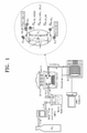
- FIG. 1 is a view illustrating a carbon dioxide photoconversion system according to an embodiment of the inventive concept.
- a reaction of a carbon dioxide photoconversion system which is represented by artificial photosynthesis, is similar to a photosynthesis reaction, in which high-energy organic materials are synthesized from water and carbon dioxide by using a light source as an energy source.
- the photosynthesis reactions in the nature system largely include light reactions, in which water is decomposed into oxygen and hydrogen while absorbing light, and dark reactions, in which carbon dioxide is reduced by using the obtained hydrogen and finally organic materials are synthesized.
- a carbon dioxide photoconversion system may largely include a carbon dioxide storage tank, a mass flow controller (MFC), a photo-reactor, a gas chromatography (GC) device, and a light source device.
- MFC mass flow controller
- GC gas chromatography
- the carbon dioxide storage tank supplies the carbon dioxide that is a reactant to the photo-reactor via the mass flow controller, and a reaction vessel generates hydrogen and oxygen through decomposition of water by using light energy while mimicking the photosynthesis reaction of the nature system and reduces the carbon dioxide by using the stored carbon dioxide, the hydrogen, and electrons excited by the energy.
- various reduction reactions and products may be present according to the number of the electrons and protons used, and the products may be formic acid, monoxide, formaldehyde, methanol, and methane.
- the products may be injected through a gas chromatography, and through this, a qualitative analysis of recognizing configurations of the products and a quantitative analysis of recognizing an amount and an increase speed of the products.
- FIG. 2 is a cross-sectional view illustrating a photo-reactor according to an embodiment of the inventive concept.
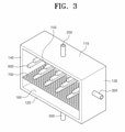
- FIG. 3 is a perspective view of a photo-reactor according to an embodiment of the inventive concept.
- FIGS. 4A and 4B are views of a photo-reactor according to an embodiment of the inventive concept, viewed from the top and the bottom.
- FIG. 4A is a plan view of the photo-reactor according to the embodiment of the inventive concept, when viewed from the top.
- FIG. 4B is a bottom view of a photo-reactor according to an embodiment of the inventive concept, when viewed from the bottom.
- a photo-reactor 10 includes a body 100, a gas injector 200, a vapor injector 300, a gas discharger 400, a liquid discharger 500, an elongate structure 600, and ventilation plate 700.
- the body 100 has a closed interior space 160, and a photocatalytic material is provided in the interior space 160 and a reaction gas and a liquefied fluid are generated from carbon dioxide through a photoconversion reaction.
- the body 100 may provide a specific space, in which the carbon dioxide is converted into the reaction gas and the liquefied fluid that may be recycled, by using the light input from the light source.
- the reaction gas may be monoxide, formic acid, formaldehyde, and methane gas
- the liquefied fluid may include water, methanol, and the like.
- the body 100 is configured to form a hexahedral shape by coupling a plurality of transparent flat plates such that the plurality of transparent flat plates are separable from each other.
- the transparent flat plates preferably include soda lime, ultraviolet ray transmitting polymethylcrylate (UV-T PMMA), quartz, and borosilicate, but the inventive concept is not limited thereto as long as the transparent flat plates may induce reflection and refraction of the light input by the light source.
- UV-T PMMA ultraviolet ray transmitting polymethylcrylate
- quartz quartz
- borosilicate borosilicate
- the transparent flat plates of the body 100 may include a ceiling plate 110, a bottom plate 120, a front plate 130, a rear plate 140, and a pair of side plates 150.
- the transparent flat plate to which light is input by the light source, includes quartz that has a high light transmission at bands of all wavelengths, and it is preferable that the other transparent flat plates include ultraviolet ray transmitting polymethyl methylcrylate.
- the ceiling plate 110 of the body 100 to which the light is input by the light source, includes quartz, and the bottom plate 120, the front plate 130, the rear plate 140, and the side plates 150 include ultraviolet ray transmitting polymethyl methylcrylate.
- a plurality of insertion grooves (not illustrated) corresponding to the size of the elongate structure 600 may be further provided on one side of an inner surface of the body 100.
- the plurality of insertion grooves may be formed on the inner surfaces of the pair of side plates 150 to be spaced apart from each other by a specific interval.
- the interior space 160 of the body 100 is coated with the photocatalytic material (not illustrated), and in detail, the inner surfaces of the ceiling plate 110, the bottom plate 120, the front plate 130, the rear plate 140, and the side plates 150 are coated with the photocatalytic material.
- the photocatalytic material includes a material selected from a group consisting of titanium dioxide, zinc oxide, zirconium oxide, cadmium sulfide, vanadium oxide, tungsten trioxide, strontium titanate, and a combination thereof.
- the photocatalytic material includes titanium dioxide, but the inventive concept is not limited thereto as long as the photocatalytic material may perform a carbon dioxide reduction reaction.
- the gas injector 200 may provide a passage, through which carbon dioxide flows.
- gas injector 200 is communicated with the body 100, and in more detail, is coupled to the ceiling plate 110 of the body 100.
- gas injector 200 is connected to an external carbon dioxide storage tank, and may supply the carbon dioxide that is necessary during the photoconversion reaction into the interior space 160 of the body 100.
- a flow meter (not illustrated) may be installed in the gas injector 200, and the gas injector 200 may inject a proper amount of carbon dioxide at a specific flow rate.
- the vapor injector 300 provides a passage, through which vapor flows.
- the vapor injector 300 is communicated with the body 100, and in more detail, is coupled to the front plate 130 of the body 100.
- the vapor injector 300 is connected to an external vapor ejecting apparatus, and may supply the vapor that is necessary during the photoconversion reaction into the interior space 160 of the body 100.
- the vapor injector 300 may inject a proper amount of water at a specific flow rate in the form of vapor, the vapor may be uniformly diffused such that a dead zone is not present in the interior space 160 of the body 100.
- the vapor injector 300 continuously injects the vapor until the photoconversion reaction is ended.
- the gas discharger 400 may discharge the reaction gas to the outside during the photoconversion reaction.
- gas discharger 400 is communicated with the body 100, and in more detail, is coupled to the rear plate 140 of the body 100.
- the gas discharger 400 is connected to an external gas chromatography device, and the gas chromatography device may separate the reaction gases generated during the photoconversion reaction according to their properties and record the compositions of the gas according to time, and may quantitatively measure an increase amount and an increase speed of the generated gases according to time.
- the generated gases are injected into the gas chromatography device through a carrier gas, such as helium, hydrogen, and nitrogen.
- a carrier gas such as helium, hydrogen, and nitrogen.
- the liquid discharger 500 may discharge the liquefied fluid to the outside during the photoconversion reaction.
- liquid discharger 500 is communicated with the body 100, and in more detail, is coupled to the bottom plate 120 of the body 100.
- liquid discharger 500 is connected to an external discharged material storage tank, and the generated liquefied fluid may be stored in the discharged material storage tank through the liquid discharger 500.
- a valve (not illustrated) may be installed in the liquid discharger 500, and a proper amount of liquefied fluid collected may be discharged to the outside through the valve.
- the elongate structures 600 are disposed to cross the interior space 160 of the body 100 in a preset direction.
- the elongate structure 600 have rod shapes, but the inventive concept is not limited thereto as long as the flows of the carbon dioxide and the vapor may become complex.
- the elongate structure 600 may be inserted into the insertion grooves formed on one side of the inner surfaces of the side plate 150 to be detachable, and the plurality of elongate structures may be disposed to be spaced apart from each other by a predetermined interval.
- all of the elongate structures 600 are coupled to the plurality of insertion grooves, but the inventive concept is not limited thereto as long as main factors, such as flow rates and material transmission rates of the carbon dioxide and the vapor may be changed.
- the number of the elongate structures 600 disposed in the body 100 may be adjusted according to the determination of the user.
- the elongate structures 600 are disposed to extend in a direction that is perpendicular to at least one of an inflow direction of the carbon dioxide through the gas injector 200 and a flow direction of the vapor through the vapor injector 300.
- outer peripheral surfaces of the elongate structures 600 may be coated with the photocatalytic material.
- various kinds of materials may be used as the photocatalytic material coated on the elongate structures 600, and the same photocatalytic material may be coated again.
- the elongate structures 600 include ultraviolet ray transmitting polymethyl methylcrylate, but the inventive concept is not limited thereto as long as the elongate structures 600 may induce reflection and refraction of the light input by the light source.
- the elongate structures 600 may include soda lime, quartz, and borosilicate.
- the elongate structures 600 changes the flows of the carbon dioxide and the vapor supplied into the interior space 160 of the body 100 and is helpful for diffusion of the carbon dioxide and the vapor in the interior of the photo-reactor 10, and accordingly, enhances photoconversion efficiency by increasing a contact area between the carbon dioxide and the vapor that are present in the interior of the photo-reactor 10 and the photocatalytic material.
- the elongate structures 600 may increase the amount of the light input to the photocatalytic material coated in the interior space 160 of the body 100 by inducing reflection and refraction of the light input by the light source.
- the ventilation plate 700 may be disposed in an area that is adjacent to the liquid discharger 500.
- the ventilation plate 700 is disposed in an area that is adjacent to the inner surface of the bottom plate 120 of the body 100, and is coupled to the inner surfaces of the front plate 130, the rear plate 140, and the side plates 150.
- the ventilation plate 700 is disposed at a location that is spaced from the bottom surface of the body 100 by a predetermined distance, and the liquefied fluid may pass through the ventilation plate 700.
- the ventilation plate 700 may include ultraviolet ray transmitting polymethyl methylcrylate, and an upper surface of the ventilation plate 700 may be coated with the photocatalytic material and a plurality of vent holes are formed therein.
- the ventilation plate 700 is disposed in the body 100, the vapor supplied into the interior space 160 of the body 100 may be prevented from being liquefied and accumulated, and may form a space, in which the accumulated water and the liquefied fluid generated during the photoconversion reaction may be stored.
- FIG. 5 is a graph depicting an amount of generated carbon monoxide according to an embodiment of the inventive concept.
- a photoconversion rate when the elongate structures 600 were not added was 0.0477 umol/gcat and a photoconversion rate when the elongate structures 600 were added was 0.10509 umol/gcat, whereby the photoconversion rates were improved by about 2.1 times when the elongate structures 600 were added.
- FIG. 6 is a view illustrating a distribution state of a volume of vapor in an interior of a photo-reactor according to time and streamline flows of the vapor in the interior of the photo-reactor according to time when a structure according to an embodiment of the inventive concept is installed.
- a distribution state of the volume of the vapor when the elongate structures 600 are disposed, and the flows of streamlines of the vapor injected through the vapor injector 300 according to the time may be compared in unit of 1 second.
- the vapor Due to the characteristics of the injection of vapor, the vapor starts to be diffused from a starting point of a specific distance according to the injection speed thereof, and as illustrated in FIG. 6 , it may be identified that the vapor diffused to an upper end and a lower end of an injection hole stays while circulating. It may be identified that the disposed elongate structures 600 brings the diffusion point of the vapor forwards, and act as an obstructive factor in the diffusion process to make the flows of the vapor complex.
- inventive concept The above detailed description exemplifies the inventive concept. Furthermore, the above-mentioned contents describe the exemplary embodiment of the inventive concept, and the inventive concept may be used in various other combinations, changes, and environments. That is, the inventive concept can be modified and corrected without departing from the scope of the inventive concept that is disclosed in the specification, the equivalent scope to the written disclosures, and/or the technical or knowledge range of those skilled in the art.
- the written embodiment describes the best state for implementing the technical spirit of the inventive concept, and various changes required in the detailed application fields and purposes of the inventive concept can be made. Accordingly, the detailed description of the inventive concept is not intended to restrict the inventive concept in the disclosed embodiment state. Furthermore, it should be construed that the attached claims include other embodiments.
Landscapes
- Chemical & Material Sciences (AREA)
- Organic Chemistry (AREA)
- Chemical Kinetics & Catalysis (AREA)
- General Health & Medical Sciences (AREA)
- Health & Medical Sciences (AREA)
- Inorganic Chemistry (AREA)
- Toxicology (AREA)
- Physics & Mathematics (AREA)
- Electromagnetism (AREA)
- Engineering & Computer Science (AREA)
- Combustion & Propulsion (AREA)
- Materials Engineering (AREA)
- Catalysts (AREA)
- Carbon And Carbon Compounds (AREA)
Abstract
Description
- The inventive concept relates to a carbon dioxide photo-reactor.
- In modern society, fossil fuels are increasingly used due to industrial developments, and thus cause global warming problems and resource depletion problems.
- Accordingly, effective means for solving the global warming problems have been studied all over the world, and as representative methods, carbon dioxide reducing projects related to technologies for collection and storage of carbon dioxide have been operated by way of showing examples or already started.
- The technologies for collection and storage of carbon dioxide are technologies for collecting carbon dioxide generated in a carbon dioxide mass discharge source, such as a petroleum factory, a thermal power plant, a cement factory, or a steel mill, which uses fossil fuels as main energy sources, and permanently isolating the collected carbon dioxide in the land and sub-bottom structures.
- However, the technologies for collection and storage of carbon dioxide have been developed considerably all over the countries, but the land environment conditions of Korea are lack in ground surface spaces topographically, so that it is difficult to secure a large storage space and there may be a possibility of a severe accident when carbon dioxide is leaked.
- Further, the technologies for collection and storage of carbon dioxide may instantaneously damage the human bodies when the concentration of carbon dioxide that is present in air increases to a specific value or more due to leakage of a large amount of carbon dioxide caused by an unintended accident, and the leakage of carbon dioxide over long time may contaminate under-ground water around a ground surface, which is used for drinking water or agricultural water by human beings, even though the amount of the leaked carbon dioxide is small.
- Accordingly, a resource circulating carbon dioxide treating technology that does not simply store carbon dioxide but is safe in an aspect of a long term is necessary.
- Embodiments of the inventive concept provide a carbon dioxide photo-reactor that may convert carbon dioxide into recyclable energy by using the carbon dioxide, light, and vapor.
- Embodiments of the inventive concept also provide a carbon dioxide photo-reactor that is helpful for diffusion of carbon dioxide and vapor in a closed interior space by changing flows of the carbon dioxide and the vapor.
- Embodiments of the inventive concept provide a carbon dioxide photo-reactor that may enhance photoconversion efficiency by increasing a contact area between carbon dioxide and vapor and a coated photocatalytic material.
- According to an aspect of the inventive concept, a carbon dioxide photo-reactor includes a body having a closed interior space, provided with a photocatalytic material in the interior space, and that generates a reaction gas and a liquefied fluid from carbon dioxide through a photoconversion reaction, a gas injector that provides a passage, through which the carbon dioxide flows, a vapor injector that provides a passage, through which vapor flows, a gas discharger, through which the generated reaction gas is discharged, a liquid discharger, through which the generated liquefied fluid is discharged, and at least one elongate structure disposed to cross the interior space in a predetermined direction.
- According to an embodiment of the inventive concept, the body may form a hexahedral shape by coupling a plurality of transparent flat plates such that the plurality of transparent flat plates are separable from each other, and, among the plurality of transparent flat plates, a transparent flat plate, to which light is input from a light source, may be formed of quartz.
- According to an embodiment of the inventive concept, the body may further include a ventilation plate disposed at a location that is spaced apart from a bottom surface by a predetermined distance, and through which the liquefied fluid passes.
- According to an embodiment of the inventive concept, the body may include at least one insertion groove formed on one side of an inner surface of the body to correspond to a size of the elongate structure.
- According to an embodiment of the inventive concept, the elongate structures may be inserted into the insertion groove to be detachable, and the plurality of elongate structures may be disposed to be spaced apart from each other by a predetermined interval.
- According to an embodiment of the inventive concept, the elongate structures may be disposed to extend in a direction that is perpendicular to at least one of an inflow direction of the carbon dioxide through the gas injector and an inflow direction of the vapor through the vapor injector.
- According to an embodiment of the inventive concept, outer peripheral surfaces of the elongate structures may be coated with the photocatalytic material.
- According to an embodiment of the inventive concept, the photocatalytic material may include a material selected from a group consisting of titanium dioxide, zinc oxide, zirconium oxide, cadmium sulfide, vanadium oxide, tungsten trioxide, strontium titanate, and a combination thereof.
- According to the carbon dioxide photo-reactor according to the embodiments of the inventive concept, carbon dioxide may be converted into recyclable energy by using the carbon dioxide, light, and vapor
- Further, the carbon dioxide photo-reactor according to the embodiments of the inventive concept may be helpful for diffusion of carbon dioxide and vapor in a closed interior space by changing flows of the carbon dioxide and the vapor
- In addition, according to the carbon dioxide photo-reactor according to the embodiments of the inventive concept, photoconversion efficiency may be enhanced by increasing a contact area between carbon dioxide and vapor and a coated photocatalytic material.
-
-
FIG. 1 is a view illustrating a carbon dioxide photoconversion system according to an embodiment of the inventive concept; -
FIG. 2 is a cross-sectional view illustrating a photo-reactor according to an embodiment of the inventive concept; -
FIG. 3 is a perspective view of a photo-reactor according to an embodiment of the inventive concept; -
FIGS. 4A and 4B are views of a photo-reactor according to an embodiment of the inventive concept, viewed from the top and the bottom; -
FIG. 5 is a graph depicting an amount of generated carbon monoxide according to an embodiment of the inventive concept; and -
FIG. 6 is a view illustrating a distribution state of a volume of vapor in an interior of a photo-reactor according to time and streamline flows of the vapor in the interior of the photo-reactor according to time when a structure according to an embodiment of the inventive concept is installed. - Hereinafter, exemplary embodiments of the inventive concept will be described in more detail with reference to the accompanying drawings. The embodiments of the inventive may be modified in various forms, and the scope of the inventive concept should not be construed to be limited to the following embodiments. The embodiments of the inventive concept are provided to describe the present inventive for an ordinary person skilled in the art more completely. Accordingly, the shapes of the components of the drawings are exaggerated to emphasize clearer description thereof.
- The configurations of the inventive concept for clearly describing a solution for the problem that is to be solved by the inventive concept will be described in detail with reference to the accompanying drawings based on a preferred embodiment of the inventive concept, in which the same reference numerals are given for the same elements in denoting the reference numerals for the elements even though they are present in different drawings, and when a drawing has to be referenced for a description of the embodiment, the elements in another drawing also may be cited.
- The embodiment of the inventive concept relates to a carbon dioxide photo-reactor and the photo-reactor in the specification pertains to a heterogeneous inorganic photocatalytic system, for example, using titanium dioxide and other semiconductor photocatalytic materials, but the inventive concept is not limited thereto and any apparatus related to a photochemical conversion system for carbon dioxide, which collects energy from a light source and converts the energy to chemical energy may be possible without any limitation. For example, it is construed that the photo-reactor may be utilized in a homogeneous reaction system using a transition metal complex, a combined system, in which various photocatalysts, such as homogeneous catalysts and heterogeneous catalysts, are combined, and a photoelectric-chemical reaction system for applying optical energy and electric energy at the same time by utilizing a photocatalytic material as an electrode.
-
FIG. 1 is a view illustrating a carbon dioxide photoconversion system according to an embodiment of the inventive concept. - A reaction of a carbon dioxide photoconversion system, which is represented by artificial photosynthesis, is similar to a photosynthesis reaction, in which high-energy organic materials are synthesized from water and carbon dioxide by using a light source as an energy source.
- The photosynthesis reactions in the nature system largely include light reactions, in which water is decomposed into oxygen and hydrogen while absorbing light, and dark reactions, in which carbon dioxide is reduced by using the obtained hydrogen and finally organic materials are synthesized.
- Accordingly, as illustrated in
FIG. 1 , a carbon dioxide photoconversion system according to the inventive concept may largely include a carbon dioxide storage tank, a mass flow controller (MFC), a photo-reactor, a gas chromatography (GC) device, and a light source device. - The carbon dioxide storage tank supplies the carbon dioxide that is a reactant to the photo-reactor via the mass flow controller, and a reaction vessel generates hydrogen and oxygen through decomposition of water by using light energy while mimicking the photosynthesis reaction of the nature system and reduces the carbon dioxide by using the stored carbon dioxide, the hydrogen, and electrons excited by the energy.
- Then, various reduction reactions and products may be present according to the number of the electrons and protons used, and the products may be formic acid, monoxide, formaldehyde, methanol, and methane.
- Furthermore, the products may be injected through a gas chromatography, and through this, a qualitative analysis of recognizing configurations of the products and a quantitative analysis of recognizing an amount and an increase speed of the products.
- Furthermore, in the carbon dioxide photoconversion system, it is important to develop a photocatalytic material that may efficiently decompose carbon dioxide and selectively allow a specific reaction such as a synthesis of methanol, but studies on the material, the shape, and the structure of a photo-reaction in consideration of the efficiency of the photoconversion reaction is necessary to substantially increase the efficiency of the carbon dioxide photoconversion system.
-
FIG. 2 is a cross-sectional view illustrating a photo-reactor according to an embodiment of the inventive concept.FIG. 3 is a perspective view of a photo-reactor according to an embodiment of the inventive concept.FIGS. 4A and 4B are views of a photo-reactor according to an embodiment of the inventive concept, viewed from the top and the bottom. - In addition,
FIG. 4A is a plan view of the photo-reactor according to the embodiment of the inventive concept, when viewed from the top.FIG. 4B is a bottom view of a photo-reactor according to an embodiment of the inventive concept, when viewed from the bottom. - As illustrated in
FIGS. 2 ,3 ,4A, and 4B , a photo-reactor 10 includes abody 100, agas injector 200, avapor injector 300, agas discharger 400, aliquid discharger 500, anelongate structure 600, andventilation plate 700. - The
body 100 has a closedinterior space 160, and a photocatalytic material is provided in theinterior space 160 and a reaction gas and a liquefied fluid are generated from carbon dioxide through a photoconversion reaction. - That is, the
body 100 may provide a specific space, in which the carbon dioxide is converted into the reaction gas and the liquefied fluid that may be recycled, by using the light input from the light source. - The reaction gas may be monoxide, formic acid, formaldehyde, and methane gas, and the liquefied fluid may include water, methanol, and the like.
- Furthermore, the
body 100 is configured to form a hexahedral shape by coupling a plurality of transparent flat plates such that the plurality of transparent flat plates are separable from each other. - The transparent flat plates preferably include soda lime, ultraviolet ray transmitting polymethylcrylate (UV-T PMMA), quartz, and borosilicate, but the inventive concept is not limited thereto as long as the transparent flat plates may induce reflection and refraction of the light input by the light source.
- In addition, the transparent flat plates of the
body 100 may include aceiling plate 110, abottom plate 120, afront plate 130, arear plate 140, and a pair ofside plates 150. - Furthermore, it is preferable that, among the transparent flat plates of the
body 100, the transparent flat plate, to which light is input by the light source, includes quartz that has a high light transmission at bands of all wavelengths, and it is preferable that the other transparent flat plates include ultraviolet ray transmitting polymethyl methylcrylate. - For example, referring to
FIG. 3 , according to the inventive concept, theceiling plate 110 of thebody 100, to which the light is input by the light source, includes quartz, and thebottom plate 120, thefront plate 130, therear plate 140, and theside plates 150 include ultraviolet ray transmitting polymethyl methylcrylate. - Furthermore, a plurality of insertion grooves (not illustrated) corresponding to the size of the
elongate structure 600 may be further provided on one side of an inner surface of thebody 100. - In more detail, the plurality of insertion grooves (not illustrated) may be formed on the inner surfaces of the pair of
side plates 150 to be spaced apart from each other by a specific interval. - Furthermore, it is preferable that the
interior space 160 of thebody 100 is coated with the photocatalytic material (not illustrated), and in detail, the inner surfaces of theceiling plate 110, thebottom plate 120, thefront plate 130, therear plate 140, and theside plates 150 are coated with the photocatalytic material. - The photocatalytic material includes a material selected from a group consisting of titanium dioxide, zinc oxide, zirconium oxide, cadmium sulfide, vanadium oxide, tungsten trioxide, strontium titanate, and a combination thereof.
- In the inventive concept, it is preferable that the photocatalytic material includes titanium dioxide, but the inventive concept is not limited thereto as long as the photocatalytic material may perform a carbon dioxide reduction reaction.
- The
gas injector 200 may provide a passage, through which carbon dioxide flows. - Furthermore, the
gas injector 200 is communicated with thebody 100, and in more detail, is coupled to theceiling plate 110 of thebody 100. - Furthermore, the
gas injector 200 is connected to an external carbon dioxide storage tank, and may supply the carbon dioxide that is necessary during the photoconversion reaction into theinterior space 160 of thebody 100. - Furthermore, a flow meter (not illustrated) may be installed in the
gas injector 200, and thegas injector 200 may inject a proper amount of carbon dioxide at a specific flow rate. - The
vapor injector 300 provides a passage, through which vapor flows. - Furthermore, the
vapor injector 300 is communicated with thebody 100, and in more detail, is coupled to thefront plate 130 of thebody 100. - Furthermore, the
vapor injector 300 is connected to an external vapor ejecting apparatus, and may supply the vapor that is necessary during the photoconversion reaction into theinterior space 160 of thebody 100. - In addition, because the
vapor injector 300 may inject a proper amount of water at a specific flow rate in the form of vapor, the vapor may be uniformly diffused such that a dead zone is not present in theinterior space 160 of thebody 100. - Furthermore, the
vapor injector 300 continuously injects the vapor until the photoconversion reaction is ended. - The
gas discharger 400 may discharge the reaction gas to the outside during the photoconversion reaction. - Furthermore, the
gas discharger 400 is communicated with thebody 100, and in more detail, is coupled to therear plate 140 of thebody 100. - Furthermore, the
gas discharger 400 is connected to an external gas chromatography device, and the gas chromatography device may separate the reaction gases generated during the photoconversion reaction according to their properties and record the compositions of the gas according to time, and may quantitatively measure an increase amount and an increase speed of the generated gases according to time. - Then, the generated gases are injected into the gas chromatography device through a carrier gas, such as helium, hydrogen, and nitrogen.
- The
liquid discharger 500 may discharge the liquefied fluid to the outside during the photoconversion reaction. - Furthermore, the
liquid discharger 500 is communicated with thebody 100, and in more detail, is coupled to thebottom plate 120 of thebody 100. - Furthermore, the
liquid discharger 500 is connected to an external discharged material storage tank, and the generated liquefied fluid may be stored in the discharged material storage tank through theliquid discharger 500. - Furthermore, a valve (not illustrated) may be installed in the
liquid discharger 500, and a proper amount of liquefied fluid collected may be discharged to the outside through the valve. - The
elongate structures 600 are disposed to cross theinterior space 160 of thebody 100 in a preset direction. - In the embodiment of the inventive concept, it is preferable that the
elongate structure 600 have rod shapes, but the inventive concept is not limited thereto as long as the flows of the carbon dioxide and the vapor may become complex. - Furthermore, the
elongate structure 600 may be inserted into the insertion grooves formed on one side of the inner surfaces of theside plate 150 to be detachable, and the plurality of elongate structures may be disposed to be spaced apart from each other by a predetermined interval. - In addition, it is preferable that all of the
elongate structures 600 are coupled to the plurality of insertion grooves, but the inventive concept is not limited thereto as long as main factors, such as flow rates and material transmission rates of the carbon dioxide and the vapor may be changed. - That is, the number of the
elongate structures 600 disposed in thebody 100 may be adjusted according to the determination of the user. - Furthermore, the
elongate structures 600 are disposed to extend in a direction that is perpendicular to at least one of an inflow direction of the carbon dioxide through thegas injector 200 and a flow direction of the vapor through thevapor injector 300. - Furthermore, outer peripheral surfaces of the
elongate structures 600 may be coated with the photocatalytic material. - In addition, various kinds of materials may be used as the photocatalytic material coated on the
elongate structures 600, and the same photocatalytic material may be coated again. - Further, it is preferable that the
elongate structures 600 include ultraviolet ray transmitting polymethyl methylcrylate, but the inventive concept is not limited thereto as long as theelongate structures 600 may induce reflection and refraction of the light input by the light source. - That is, the
elongate structures 600 may include soda lime, quartz, and borosilicate. - The
elongate structures 600 changes the flows of the carbon dioxide and the vapor supplied into theinterior space 160 of thebody 100 and is helpful for diffusion of the carbon dioxide and the vapor in the interior of the photo-reactor 10, and accordingly, enhances photoconversion efficiency by increasing a contact area between the carbon dioxide and the vapor that are present in the interior of the photo-reactor 10 and the photocatalytic material. - Furthermore, in the embodiment of the inventive concept, the
elongate structures 600 may increase the amount of the light input to the photocatalytic material coated in theinterior space 160 of thebody 100 by inducing reflection and refraction of the light input by the light source. - The
ventilation plate 700 may be disposed in an area that is adjacent to theliquid discharger 500. - In more detail, the
ventilation plate 700 is disposed in an area that is adjacent to the inner surface of thebottom plate 120 of thebody 100, and is coupled to the inner surfaces of thefront plate 130, therear plate 140, and theside plates 150. - That is, the
ventilation plate 700 is disposed at a location that is spaced from the bottom surface of thebody 100 by a predetermined distance, and the liquefied fluid may pass through theventilation plate 700. - Furthermore, the
ventilation plate 700 may include ultraviolet ray transmitting polymethyl methylcrylate, and an upper surface of theventilation plate 700 may be coated with the photocatalytic material and a plurality of vent holes are formed therein. - Accordingly, because the
ventilation plate 700 is disposed in thebody 100, the vapor supplied into theinterior space 160 of thebody 100 may be prevented from being liquefied and accumulated, and may form a space, in which the accumulated water and the liquefied fluid generated during the photoconversion reaction may be stored. -
FIG. 5 is a graph depicting an amount of generated carbon monoxide according to an embodiment of the inventive concept. - As illustrated in
FIG. 5 , only an amount of monoxide generated by the photo-reactor 10 according to the embodiment of the inventive concept through a photoconversion reaction of carbon dioxide was measured and is illustrated. - A photoconversion rate when the
elongate structures 600 were not added was 0.0477 umol/gcat and a photoconversion rate when theelongate structures 600 were added was 0.10509 umol/gcat, whereby the photoconversion rates were improved by about 2.1 times when theelongate structures 600 were added. -
FIG. 6 is a view illustrating a distribution state of a volume of vapor in an interior of a photo-reactor according to time and streamline flows of the vapor in the interior of the photo-reactor according to time when a structure according to an embodiment of the inventive concept is installed. - Referring to
FIG. 6 , a distribution state of the volume of the vapor when theelongate structures 600 are disposed, and the flows of streamlines of the vapor injected through thevapor injector 300 according to the time may be compared in unit of 1 second. - Due to the characteristics of the injection of vapor, the vapor starts to be diffused from a starting point of a specific distance according to the injection speed thereof, and as illustrated in
FIG. 6 , it may be identified that the vapor diffused to an upper end and a lower end of an injection hole stays while circulating. It may be identified that the disposedelongate structures 600 brings the diffusion point of the vapor forwards, and act as an obstructive factor in the diffusion process to make the flows of the vapor complex. - The above detailed description exemplifies the inventive concept. Furthermore, the above-mentioned contents describe the exemplary embodiment of the inventive concept, and the inventive concept may be used in various other combinations, changes, and environments. That is, the inventive concept can be modified and corrected without departing from the scope of the inventive concept that is disclosed in the specification, the equivalent scope to the written disclosures, and/or the technical or knowledge range of those skilled in the art. The written embodiment describes the best state for implementing the technical spirit of the inventive concept, and various changes required in the detailed application fields and purposes of the inventive concept can be made. Accordingly, the detailed description of the inventive concept is not intended to restrict the inventive concept in the disclosed embodiment state. Furthermore, it should be construed that the attached claims include other embodiments.
Claims (8)
- A carbon dioxide photo-reactor(10) comprising:a body(100) having a closed interior space(160), provided with a photocatalytic material in the interior space(160), and configured to generate a reaction gas and a liquefied fluid from carbon dioxide through a photoconversion reaction;a gas injector(200) configured to provide a passage, through which the carbon dioxide flows;a vapor injector(300) configured to provide a passage, through which vapor flows;a gas discharger(400), through which the generated reaction gas is discharged;a liquid discharger(500), through which the generated liquefied fluid is discharged; andat least one elongate structure(600) disposed to cross the interior space(160) in a predetermined direction.
- The carbon dioxide photo-reactor(10) of claim 1, wherein the body(100) forms a hexahedral shape by coupling a plurality of transparent flat plates such that the plurality of transparent flat plates are separable from each other, and
wherein, among the plurality of transparent flat plates, a transparent flat plate, to which light is input from a light source, is formed of quartz. - The carbon dioxide photo-reactor(10) of claim 1, wherein the body(100) further includes:
a ventilation plate(700) disposed at a location that is spaced apart from a bottom surface by a predetermined distance, and through which the liquefied fluid passes. - The carbon dioxide photo-reactor(10) of claim 1, wherein the body(100) includes:
at least one insertion groove formed on one side of an inner surface of the body to correspond to a size of the elongate structure(600). - The carbon dioxide photo-reactor(10) of claim 4, wherein the elongate structures(600) are inserted into the insertion groove to be detachable, and the plurality of elongate structures(600) are disposed to be spaced apart from each other by a predetermined interval.
- The carbon dioxide photo-reactor(10) of claim 5, wherein the elongate structures(600) are disposed to extend in a direction that is perpendicular to at least one of an inflow direction of the carbon dioxide through the gas injector(200) and an inflow direction of the vapor through the vapor injector(300).
- The carbon dioxide photo-reactor(10) of claim 6, wherein outer peripheral surfaces of the elongate structures(600) are coated with the photocatalytic material.
- The carbon dioxide photo-reactor(10) of claim 1, wherein the photocatalytic material includes a material selected from a group consisting of titanium dioxide, zinc oxide, zirconium oxide, cadmium sulfide, vanadium oxide, tungsten trioxide, strontium titanate, and a combination thereof.
Applications Claiming Priority (2)
| Application Number | Priority Date | Filing Date | Title |
|---|---|---|---|
| KR1020190038766A KR102237029B1 (en) | 2019-04-03 | 2019-04-03 | Carbon dioxide photo-conversion reactor |
| PCT/KR2020/002000 WO2020204346A1 (en) | 2019-04-03 | 2020-02-13 | Carbon dioxide photoconversion reactor |
Publications (2)
| Publication Number | Publication Date |
|---|---|
| EP3950116A1 true EP3950116A1 (en) | 2022-02-09 |
| EP3950116A4 EP3950116A4 (en) | 2023-01-04 |
Family
ID=72667399
Family Applications (1)
| Application Number | Title | Priority Date | Filing Date |
|---|---|---|---|
| EP20783067.0A Pending EP3950116A4 (en) | 2019-04-03 | 2020-02-13 | Carbon dioxide photoconversion reactor |
Country Status (4)
| Country | Link |
|---|---|
| US (1) | US20220072501A1 (en) |
| EP (1) | EP3950116A4 (en) |
| KR (1) | KR102237029B1 (en) |
| WO (1) | WO2020204346A1 (en) |
Families Citing this family (3)
| Publication number | Priority date | Publication date | Assignee | Title |
|---|---|---|---|---|
| KR102292325B1 (en) * | 2021-01-25 | 2021-08-24 | 숙명여자대학교산학협력단 | Gas diffusion reactor |
| KR102668799B1 (en) * | 2021-06-28 | 2024-05-29 | 한국과학기술원 | Apparatus for electrochemical reaction and method for electrochemical reaction |
| CN119327386A (en) * | 2024-10-16 | 2025-01-21 | 中国科学技术大学 | A photocatalytic reaction system and photocatalytic reaction method for reducing CO2/N2 by water vapor |
Family Cites Families (15)
| Publication number | Priority date | Publication date | Assignee | Title |
|---|---|---|---|---|
| JPH0671130A (en) * | 1992-08-28 | 1994-03-15 | Ebara Corp | Apparatus for treating gas containing vapor of water-soluble organic substance |
| JPH1133357A (en) * | 1997-07-17 | 1999-02-09 | Sumitomo Heavy Ind Ltd | Photocatalyst reaction device |
| KR100714849B1 (en) * | 2005-11-17 | 2007-05-04 | 경희대학교 산학협력단 | Photocatalyst composition, its fixing method and continuous photocatalyst reactor using the photocatalyst |
| US20090313886A1 (en) * | 2008-06-24 | 2009-12-24 | Sundrop Fuels, Inc. | Various methods and apparatus for solar assisted chemical and energy processes |
| US8591730B2 (en) * | 2009-07-30 | 2013-11-26 | Siemens Pte. Ltd. | Baffle plates for an ultraviolet reactor |
| US8946112B2 (en) * | 2009-10-30 | 2015-02-03 | Empire Technology Development Llc | Photocatalytic material for splitting oxides of carbon |
| JP2011104515A (en) * | 2009-11-17 | 2011-06-02 | Ihi Corp | Photocatalytic reaction apparatus |
| CN102770194A (en) * | 2010-01-14 | 2012-11-07 | 费伦茨·梅萨罗斯 | Method for reducing CO2 components in flue gas and atmospheric gas and equipment for implementing the method |
| GB201018555D0 (en) * | 2010-11-03 | 2010-12-15 | Albagaia Ltd | Fluid treatment apparatus |
| KR101596439B1 (en) * | 2011-10-24 | 2016-02-22 | 서강대학교산학협력단 | Reducing apparatus and reducing method of carbon dioxide using solar light |
| US8926899B1 (en) * | 2013-01-10 | 2015-01-06 | Dust Free, Lp | Photocatalytic devices |
| JP6013208B2 (en) * | 2013-01-23 | 2016-10-25 | 住友精密工業株式会社 | Catalytic reactor |
| CN203244918U (en) * | 2013-05-09 | 2013-10-23 | 重庆融通机电设备有限公司 | Photocatalytic oxidation deodorization device |
| CN108472583A (en) * | 2015-12-22 | 2018-08-31 | 国际壳牌研究有限公司 | A kind of reactor for reducing nitrogen oxides |
| CN207281024U (en) * | 2017-09-22 | 2018-04-27 | 浙江工商大学 | A kind of visual photocatalysis detection device |
-
2019
- 2019-04-03 KR KR1020190038766A patent/KR102237029B1/en active Active
-
2020
- 2020-02-13 WO PCT/KR2020/002000 patent/WO2020204346A1/en not_active Ceased
- 2020-02-13 US US17/428,894 patent/US20220072501A1/en active Pending
- 2020-02-13 EP EP20783067.0A patent/EP3950116A4/en active Pending
Also Published As
| Publication number | Publication date |
|---|---|
| EP3950116A4 (en) | 2023-01-04 |
| KR102237029B1 (en) | 2021-04-07 |
| US20220072501A1 (en) | 2022-03-10 |
| KR20200117107A (en) | 2020-10-14 |
| WO2020204346A1 (en) | 2020-10-08 |
Similar Documents
| Publication | Publication Date | Title |
|---|---|---|
| US20220072501A1 (en) | Carbon dioxide photo-reactor | |
| Thompson et al. | Review and analysis of CO2 photoreduction kinetics | |
| Geng et al. | Highly efficient water dissociation on anatase TiO2 (101) | |
| Centi et al. | Opportunities and prospects in the chemical recycling of carbon dioxide to fuels | |
| Pettersson et al. | IR spectroscopic study of H2O2, HDO2, and D2O2 isolated in Ar, Kr, and Xe matrices | |
| Wang et al. | Defects and internal electric fields synergistically optimized g-C3N4− x/BiOCl/WO2. 92 heterojunction for photocatalytic NO deep oxidation | |
| US20200291343A1 (en) | OPTOFLUIDIC PHOTOBIOREACTOR APPARATUS, METHOD, and APPLICATIONS | |
| Mohan et al. | Hybrid photo-and thermal catalyst system for continuous CO2 reduction | |
| WO2008089523A1 (en) | Carbon dioxide sequestration and capture | |
| Tsydenov et al. | Toward the design of asymmetric photocatalytic membranes for hydrogen production: Preparation of TiO2-based membranes and their properties | |
| Resta et al. | Ammonia oxidation over a Pt25Rh75 (001) model catalyst surface: an operando study | |
| Vorontsov et al. | Photocatalysis: Light energy conversion for the oxidation, disinfection, and decomposition of water | |
| Knizek et al. | Acidic hydrogen enhanced photocatalytic reduction of CO2 on planetary surfaces | |
| US8303917B2 (en) | System and method for producing hydrogen from seawater | |
| Salas | Photocatalytic Water Splitting using a Modified Pt-TiO2. Kinetic Modeling and Hydrogen Production Efficiency | |
| Civis et al. | Abiotic formation of methane and prebiotic molecules on Mars and other planets | |
| Wu et al. | Decomposition of dimethyl methylphosphonate vapor on ultrathin-film titania photocatalytic light absorber | |
| KR101376757B1 (en) | Photocatalytic device for carbon dioxide methanation reaction | |
| Ryason | Hydrogen quantum yields in the 360 nm photolysis of Eu2+ solutions and their relationship to photochemical fuel formation | |
| US20150375192A1 (en) | Commercial-Scale Gamma Radiation Carbon Dioxide Reduction | |
| KR102826305B1 (en) | Space and energy efficient apparatus and method to remove tritium from wastewaters | |
| Chausse Calbet | Hydrogen photochemical production in a microreactor with Au/TiO2 nanoparticles | |
| CN223082767U (en) | A photocatalytic reactor for turbid solutions | |
| US20220288561A1 (en) | Porous titania photocatalyst on quartz fibers and methods of using the same for chemical-free uv-aop in water treatment | |
| JP2011105534A (en) | Hydrogen supply apparatus for internal combustion engine and fuel cell |
Legal Events
| Date | Code | Title | Description |
|---|---|---|---|
| STAA | Information on the status of an ep patent application or granted ep patent |
Free format text: STATUS: THE INTERNATIONAL PUBLICATION HAS BEEN MADE |
|
| PUAI | Public reference made under article 153(3) epc to a published international application that has entered the european phase |
Free format text: ORIGINAL CODE: 0009012 |
|
| STAA | Information on the status of an ep patent application or granted ep patent |
Free format text: STATUS: REQUEST FOR EXAMINATION WAS MADE |
|
| 17P | Request for examination filed |
Effective date: 20210804 |
|
| AK | Designated contracting states |
Kind code of ref document: A1 Designated state(s): AL AT BE BG CH CY CZ DE DK EE ES FI FR GB GR HR HU IE IS IT LI LT LU LV MC MK MT NL NO PL PT RO RS SE SI SK SM TR |
|
| DAV | Request for validation of the european patent (deleted) | ||
| DAX | Request for extension of the european patent (deleted) | ||
| A4 | Supplementary search report drawn up and despatched |
Effective date: 20221205 |
|
| RIC1 | Information provided on ipc code assigned before grant |
Ipc: C01B 32/50 20170101ALI20221129BHEP Ipc: B01J 8/00 20060101ALI20221129BHEP Ipc: C01B 32/40 20170101ALI20221129BHEP Ipc: C01B 3/04 20060101ALI20221129BHEP Ipc: B01J 19/12 20060101AFI20221129BHEP |
|
| P01 | Opt-out of the competence of the unified patent court (upc) registered |
Effective date: 20230529 |