EP3950074A1 - Running method determination device, running-method determination method, and program - Google Patents
Running method determination device, running-method determination method, and program Download PDFInfo
- Publication number
- EP3950074A1 EP3950074A1 EP20778187.3A EP20778187A EP3950074A1 EP 3950074 A1 EP3950074 A1 EP 3950074A1 EP 20778187 A EP20778187 A EP 20778187A EP 3950074 A1 EP3950074 A1 EP 3950074A1
- Authority
- EP
- European Patent Office
- Prior art keywords
- running
- running method
- user
- determination device
- method determination
- Prior art date
- Legal status (The legal status is an assumption and is not a legal conclusion. Google has not performed a legal analysis and makes no representation as to the accuracy of the status listed.)
- Pending
Links
- 238000000034 method Methods 0.000 title claims abstract description 178
- 239000013598 vector Substances 0.000 claims abstract description 74
- 230000001133 acceleration Effects 0.000 claims abstract description 36
- 230000033001 locomotion Effects 0.000 claims description 59
- 210000002683 foot Anatomy 0.000 claims description 44
- 210000004744 fore-foot Anatomy 0.000 claims description 10
- 210000000452 mid-foot Anatomy 0.000 claims description 9
- 230000005540 biological transmission Effects 0.000 claims description 3
- 238000005259 measurement Methods 0.000 abstract description 30
- 239000002131 composite material Substances 0.000 abstract 2
- 238000004458 analytical method Methods 0.000 description 28
- 238000012549 training Methods 0.000 description 14
- 238000010586 diagram Methods 0.000 description 13
- 238000004891 communication Methods 0.000 description 11
- 238000005070 sampling Methods 0.000 description 10
- 230000001141 propulsive effect Effects 0.000 description 7
- 241000023308 Acca Species 0.000 description 3
- 101100000438 Mus musculus Acacb gene Proteins 0.000 description 3
- 238000012545 processing Methods 0.000 description 3
- 238000005401 electroluminescence Methods 0.000 description 2
- 208000027418 Wounds and injury Diseases 0.000 description 1
- 230000006378 damage Effects 0.000 description 1
- 238000009795 derivation Methods 0.000 description 1
- 208000014674 injury Diseases 0.000 description 1
- 210000003127 knee Anatomy 0.000 description 1
- 239000004973 liquid crystal related substance Substances 0.000 description 1
- 230000003319 supportive effect Effects 0.000 description 1
- 238000010897 surface acoustic wave method Methods 0.000 description 1
Images



Classifications
-
- A—HUMAN NECESSITIES
- A61—MEDICAL OR VETERINARY SCIENCE; HYGIENE
- A61B—DIAGNOSIS; SURGERY; IDENTIFICATION
- A61B5/00—Measuring for diagnostic purposes; Identification of persons
- A61B5/103—Measuring devices for testing the shape, pattern, colour, size or movement of the body or parts thereof, for diagnostic purposes
- A61B5/11—Measuring movement of the entire body or parts thereof, e.g. head or hand tremor or mobility of a limb
- A61B5/1123—Discriminating type of movement, e.g. walking or running
-
- A—HUMAN NECESSITIES
- A63—SPORTS; GAMES; AMUSEMENTS
- A63B—APPARATUS FOR PHYSICAL TRAINING, GYMNASTICS, SWIMMING, CLIMBING, OR FENCING; BALL GAMES; TRAINING EQUIPMENT
- A63B24/00—Electric or electronic controls for exercising apparatus of preceding groups; Controlling or monitoring of exercises, sportive games, training or athletic performances
- A63B24/0062—Monitoring athletic performances, e.g. for determining the work of a user on an exercise apparatus, the completed jogging or cycling distance
-
- A—HUMAN NECESSITIES
- A63—SPORTS; GAMES; AMUSEMENTS
- A63B—APPARATUS FOR PHYSICAL TRAINING, GYMNASTICS, SWIMMING, CLIMBING, OR FENCING; BALL GAMES; TRAINING EQUIPMENT
- A63B69/00—Training appliances or apparatus for special sports
- A63B69/0028—Training appliances or apparatus for special sports for running, jogging or speed-walking
-
- A—HUMAN NECESSITIES
- A63—SPORTS; GAMES; AMUSEMENTS
- A63B—APPARATUS FOR PHYSICAL TRAINING, GYMNASTICS, SWIMMING, CLIMBING, OR FENCING; BALL GAMES; TRAINING EQUIPMENT
- A63B2220/00—Measuring of physical parameters relating to sporting activity
- A63B2220/40—Acceleration
- A63B2220/44—Angular acceleration
-
- A—HUMAN NECESSITIES
- A63—SPORTS; GAMES; AMUSEMENTS
- A63B—APPARATUS FOR PHYSICAL TRAINING, GYMNASTICS, SWIMMING, CLIMBING, OR FENCING; BALL GAMES; TRAINING EQUIPMENT
- A63B2220/00—Measuring of physical parameters relating to sporting activity
- A63B2220/50—Force related parameters
- A63B2220/51—Force
- A63B2220/53—Force of an impact, e.g. blow or punch
-
- A—HUMAN NECESSITIES
- A63—SPORTS; GAMES; AMUSEMENTS
- A63B—APPARATUS FOR PHYSICAL TRAINING, GYMNASTICS, SWIMMING, CLIMBING, OR FENCING; BALL GAMES; TRAINING EQUIPMENT
- A63B2220/00—Measuring of physical parameters relating to sporting activity
- A63B2220/62—Time or time measurement used for time reference, time stamp, master time or clock signal
-
- A—HUMAN NECESSITIES
- A63—SPORTS; GAMES; AMUSEMENTS
- A63B—APPARATUS FOR PHYSICAL TRAINING, GYMNASTICS, SWIMMING, CLIMBING, OR FENCING; BALL GAMES; TRAINING EQUIPMENT
- A63B2220/00—Measuring of physical parameters relating to sporting activity
- A63B2220/80—Special sensors, transducers or devices therefor
- A63B2220/803—Motion sensors
-
- A—HUMAN NECESSITIES
- A63—SPORTS; GAMES; AMUSEMENTS
- A63B—APPARATUS FOR PHYSICAL TRAINING, GYMNASTICS, SWIMMING, CLIMBING, OR FENCING; BALL GAMES; TRAINING EQUIPMENT
- A63B2220/00—Measuring of physical parameters relating to sporting activity
- A63B2220/80—Special sensors, transducers or devices therefor
- A63B2220/83—Special sensors, transducers or devices therefor characterised by the position of the sensor
- A63B2220/836—Sensors arranged on the body of the user
-
- A—HUMAN NECESSITIES
- A63—SPORTS; GAMES; AMUSEMENTS
- A63B—APPARATUS FOR PHYSICAL TRAINING, GYMNASTICS, SWIMMING, CLIMBING, OR FENCING; BALL GAMES; TRAINING EQUIPMENT
- A63B2225/00—Miscellaneous features of sport apparatus, devices or equipment
- A63B2225/50—Wireless data transmission, e.g. by radio transmitters or telemetry
- A63B2225/54—Transponders, e.g. RFID
Definitions
- the present disclosure relates to a running method determination device, a running-method determination method, and a program that determine running methods.
- training systems that receive data from a motion monitor measuring performance of a speed, pace, distance, and the like of a runner during running to provide a user with feedback including training information such as whether the user satisfies a specific training standard (for example, see JP 2012-228568 A ).
- the present disclosure has been conceived in view of the above-described problems, and has an object of providing a running method determination device, a running-method determination method, and a program that can provide efficient training.
- a running method determination device includes:
- FIG. 1 A configuration of this embodiment is described with reference to FIGs. 1 and 2 .
- a running method determination system 1 in this embodiment is described with reference to FIG. 1 .
- FIG. 1 is a block diagram showing the running method determination system.
- the running method determination system 1 includes a running method determination device 10 and a measurement recording device 20.
- the running method determination device 10 is a device that determines a running method of a user by using motion data (ex. acceleration data in three axial directions) of the user (measurement target person) acquired from the measurement recording device 20.
- the running method determination device 10 is, for example, a smartphone, a laptop PC (personal computer), a desktop PC, a tablet PC, or the like. In the description hereinbelow, the running method determination device 10 is a smartphone.
- the measurement recording device 20 is a device that measures and records accelerations in the three axial directions when the user runs.
- the measurement recording device 20 includes, for example, an accessory belt B, as shown in FIG. 2 , and the measurement recording device 20 is fixed at the position of the user's waist with the belt B.
- the left-right direction is defined as an X-axis, the front-back direction as a Y-axis, and the top-bottom direction as a Z-axis.
- the leftward direction is positive and the rightward direction is negative.
- the Y-axis the opposite of the forward movement direction is positive, and the forward movement direction is negative.
- On the Z axis the upward direction is positive, and the downward direction is negative.
- the measurement recording device 20 may include a clip instead of the belt B, and the measurement recording device 20 may be fixed at the position of the user's waist by fastening the clip to the running clothes.
- FIG. 3A is a block diagram showing a functional configuration of the running method determination device 10.
- the running method determination device 10 includes a central processing unit (CPU) 11, an operation interface 12, a random access memory (RAM) 13, a display 14, a storage 15, and a communication unit 16.
- the components of the running method determination device 10 are connected to each other by a bus 17.
- the CPU (acquisition means, determination means, derivation means) 11 controls the components of the running method determination device 10.
- the CPU 11 reads a program(s) specified from system programs and application programs stored in the storage 15, deploys the read program(s) in the RAM 13, and performs processing in cooperation with the deployed program(s).
- the operation interface 12 which includes a touch panel, for example, receives a touch operation from the user, and outputs the operation information to the CPU 11.
- the touch panel is formed integrally with the display 14, and detects the XY coordinates at a contact position on the display 14 by the user by various types of methods of a capacitance method, a resistance film method, and a ultrasonic surface acoustic wave method, for example.
- the touch panel outputs position signals concerning the XY coordinates of the contact position to the CPU 11.
- the RAM 13 is a volatile memory, and forms a work area temporarily storing various kinds of data and programs.
- the display 14 includes an LCD (liquid crystal display), an EL (electro luminescence) display, or the like, and displays various screens according to a display information command by the CPU 11.
- LCD liquid crystal display
- EL electro luminescence
- the storage 15 includes, for example, a flash memory, an EEPROM (electrically erasable programmable ROM), an HDD (hard disk drive), and the like.
- the storage 15 stores a system program(s), an application program(s), data necessary for execution of those programs by the CPU 11, and the like.
- the storage 15 stores running methods determined by execution of a running method determination process described later (see FIG. 5 ), motion analysis data (see FIG. 4 ), and the like.
- the communication unit 16 receives the motion data at the time of running training from the measurement recording device 20 or transmits the running methods and the motion analysis data stored in the storage 15 to an external device other than the running method determination device 10 or the measurement recording device 20, and is, for example, a communication unit that uses a wireless communication standard such as Bluetooth (registered trademark) and a wired communication unit such as a USB terminal.
- a wireless communication standard such as Bluetooth (registered trademark)
- a wired communication unit such as a USB terminal.
- FIG. 3B is a block diagram showing a functional configuration of the measurement recording device 20.
- the measurement recording device 20 includes a CPU 21, an operation interface 22, a RAM 23, a sensor 24, a display 25, a storage 26, and a communication unit 27.
- the components of the measurement recording device 20 are connected to each other by a bus 28.
- the CPU 21 controls the components of the measurement recording device 20.
- the CPU 21 reads a program(s) specified from system programs and application programs stored in the storage 26, deploys the read program(s) in the RAM 23, and performs processing in cooperation with the deployed program(s).
- the operation interface 22 includes a power button (not shown in the drawings) switching the power supply between on and off, a start/stop button (not shown in the drawings) commanding the start and stop of data acquisition, and the like, and the CPU 21 controls the components based on the commands from the operation interface 22.
- the RAM 23 is a volatile memory and forms a work area temporarily storing various kinds of data and programs.
- the sensor 24 includes a motion sensor that can detect the motion of the measurement recording device 20 such as a three-axis acceleration sensor, a gyro sensor, and a geomagnetic sensor, and a GPS receiver that can acquire the positional information of the measurement recording device 20, and outputs the measurement results to the CPU 21.
- a motion sensor that can detect the motion of the measurement recording device 20 such as a three-axis acceleration sensor, a gyro sensor, and a geomagnetic sensor
- a GPS receiver that can acquire the positional information of the measurement recording device 20, and outputs the measurement results to the CPU 21.
- the display 25 is a display unit including multiple LED lamps, and can display the state of data transmission (for example, whether data is being transmitted) and the on/off state of the GPS receiver.
- the storage 26 includes a flash memory, and an EEPROM.
- the storage 26 stores a system program(s), an application program(s), data necessary for execution of those programs by the CPU 21, and the like.
- the storage 26 stores motion data (ex. the acceleration data of the three-axial directions) at the time of running.
- the acceleration data of the three-axial directions is sampled at a predetermined sampling period (ex. 200Hz).
- the communication unit 27 transmits the motion data at the time of running based on the control of the CPU 21 to the running method determination device 10, and is, for example, a communication unit that uses a wireless communication standard such as Bluetooth (registered trademark) and a wired communication unit such as a USB terminal.
- a wireless communication standard such as Bluetooth (registered trademark)
- a wired communication unit such as a USB terminal.
- FIG. 4 is an example of the motion analysis data used in determination of the running method.
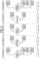
- FIG. 5 shows steps in the determination of the running method.
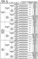
- FIG. 6 is a list showing determined running methods.
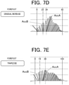
- FIGs. 7A to 7E are explanatory diagrams showing characteristics of determined running methods.
- the motion analysis data used in the determination of the running methods is described with reference to FIG. 4 .
- the motion analysis data is data derived by the running method determination device 10 based on the motion data (the acceleration of the three-axial directions) acquired from the measurement recording device 20.
- the motion analysis data shown in FIG. 4 is motion analysis data at some point at the time of running.
- the running method determination device 10 can derive the motion analysis data at every point from the start to the end of running based on the motion data and thereby determine the running method at every point.
- the elapsed time is indicated on the horizontal axis, and the resultant vector of the acceleration vector on the Z-axis (see FIG. 2 ) (in the vertical direction) and the acceleration vector on the Y-axis (see FIG. 2 ) (in the horizontal direction) are shown at each sampling point of time as an initial point.
- the length of the line of the resultant vector indicates the magnitude of the acceleration
- the inclination of the line of the resultant vector indicates that the opposite direction of time elapse from the sampling point of time as the initial point, it indicates that the concerning acceleration serves as a brake on running
- the inclination of the line of the resultant vector is in the forward direction of time elapse from the sampling point of time as the initial point, it indicates that the concerning acceleration serves as a propulsion on running.
- the angle of the resultant vector is an angle formed by the radius (ray) extending leftward on the horizontal axis from the sampling point of time of the concerning resultant vector as the initial point rotating to overlap the concerning resultant vector (rotation angle).
- the period of one cycle since one foot (ex. left foot) touches the ground until that one foot touches the ground the next time is converted (normalized) to 400 points.
- the start point of a running cycle is defined as a sampling point "0" and the end point of the running cycle as a sampling point "399.”
- the running method determination in the present disclosure is based on the value of the acceleration of the resultant vector or the angle of the resultant vector at a specific timing in two stage sections of braking and propulsion defined by dividing a running cycle of one foot (ex. left foot) on the above-referenced motion analysis data.
- the running method determination device 10 first determines whether the value of the acceleration of the Ath (ex. second) resultant vector in the section of braking in one running cycle of one foot (ex. left foot) in the above-described motion analysis data is smaller than the first threshold value (ex. 13 m/s2), equal to or greater than the first threshold value, smaller than the second threshold value (ex. 17 m/s2) or equal to or greater than the second threshold value.
- the second resultant vector is the resultant vector at the sampling point "1" in FIG. 4 .
- the running method determination is based on the value of the acceleration of the resultant vector at a timing when the Ath (ex. second) resultant vector in the section of braking in one running cycle of one foot (ex. left foot) is calculated.
- the running method determination device 10 determines whether the angle of the Bth (ex. fifth) resultant vector in the section of braking in one running cycle of one foot (ex. left foot) in the above-described motion analysis data is smaller than the third threshold value (ex. 45°) or equal to or greater than the third threshold value.
- the fifth resultant vector is the resultant vector at the sampling point "4" in FIG. 4 .
- the running method determination device 10 determines whether the value of the acceleration of the Bth (ex. fifth) resultant vector in the section of braking in one running cycle of one foot (ex. left foot) in the above-described motion analysis data is smaller than the fourth threshold value (ex. 30 m/s2), or equal to or greater than the fourth threshold value.
- the running method determination is based on the angle of the value of the acceleration of the resultant vector and the angle of the resultant vector at a timing when the Bth (ex. 5th) resultant vector in the section of braking in one running cycle of one foot (ex. left foot).
- the running method determination device 10 determines whether the angle of the resultant vector of the maximum brake in the section of braking in one running cycle of one foot (ex. left foot) in the above-described motion analysis data is smaller than the fifth threshold value (ex. 60°) or equal to or greater than the fifth threshold value.
- the resultant vector of the maximum brake is the resultant vector with the maximum acceleration among the resultant vectors that serve as brakes.
- the running method determination is based on the angle of the resultant vector at a timing when the resultant vector with the maximum resultant vector in the section of braking in one cycle of one foot (ex. left foot) is calculated.
- the running method determination device 10 determines whether the angle of the resultant vector of the maximum propulsive acceleration in the section of propulsion in one running cycle of one foot (ex. left foot) in the above-described motion analysis data is smaller than the sixth threshold value (ex. 100°), equal to or greater than the fifth threshold value, smaller than the seventh threshold value (ex. 110°), or equal to or greater than the seventh threshold value (ex. 110°).
- the resultant vector of the maximum propulsive acceleration is the resultant vector with the maximum acceleration among the resultant vectors that serve as propulsive forces.
- the running method determination is based on the angle of the resultant vector at a timing when the resultant vector with the maximum resultant vector in the section of propulsion in one running cycle of one foot (ex. left foot) is calculated.
- the running method determination device 10 determines one pattern from three patterns in the first determination, determines one pattern from two patterns each in the second determination, the three determination, and the fourth determination, determines one pattern from three patterns in the fifth determination, and thereby can determine the running method as one type in the section of braking from five types of reverse-L/wide-V/gradual increase/symmetrical-V/trapezoid, and also as one from detailed classifications (reverse-L 1 to 18 for the reverse-L type, wide-V 1 to 27 for the wide-V type, gradual increase 1 to 9 for the gradual increase type, symmetrical-V 1 to 9 for the symmetrical-V type, trapezoid 1 to 9 for the trapezoid type).
- the reverse-L type is a running method with a shape formed by the resultant vector AccA of the maximum propulsive acceleration and the resultant vector AccB of the maximum brake being a reverse-L shape.
- the reverse-L type is classified into a heel-strike running method characterized in that the foot touches the ground from the heel.
- the wide-V type is a running method with a shape formed by the resultant vector AccA of the maximum propulsive acceleration and the resultant vector AccB of the maximum brake being a V-shape wide to the left and right.
- the wide-V type is classified into a midfoot running method characterized in that the foot touches the ground in a horizontal state.
- the symmetrical-V type is a running method with a shape formed by the resultant vector AccA of the maximum propulsive acceleration and the resultant vector AccB of the maximum brake being a V-shape symmetrically wide to the left and right.
- the symmetrical-V type is classified into a midfoot running method similarly to the wide-V type, but may be classified into a midfoot running method closer to a forefoot running method as a detailed classification.
- the gradual increase type is a running method with a shape of silhouette formed by the resultant vectors expanding rightward.
- the gradual increase type is classified into a forefoot running method characterized in that the foot is landed from the toe.
- the trapezoid type is a running method characterized in that a shape of silhouette formed by the resultant vectors is a trapezoid.
- the trapezoid type is classified into a forefoot running method similarly to the gradual increase type, but may be classified into a forefoot running method with a large knee flexion.
- the running method determination device 10 shows results of the above-described determination (ex. type in the section of braking, detailed classification) and/or the running method classification (heel strike/midfoot/forefoot) on the display 14.
- the running method determination device 10 may also show the motion analysis data showing the resultant vectors shown in FIG. 4 together so that the user can visually comprehend their type of running.
- the running method determination device 10 may store the motion analysis data of first-class runners and show the motion analysis data of a first-class runner who runs by the same type of methods as the user with their motion analysis data so that the user can visually comprehend the comparison between their own running and an ideal type of running method.
- the running method determination device 10 may present advice or supportive training to make the running method more appropriate or present risk of injury based on the results of the determination ((ex. type in the section of braking, detailed classification) or the running method classification (heel strike/midfoot/forefoot).
- the running method determination device 10 acquires the motion data during their running, and determines the running method of the user based on the concerning motion data. Specifically, the running method determination device 10 calculates the resultant vectors, the sum of the acceleration vectors in the three-axial directions, based on the acceleration data acquired from the measurement recording device 20, and determines the user's running method based on the calculated resultant vectors.
- the running method determination device 10 can determine the user's running method, it is possible to make it easier for the user to comprehend the determined running method and make them correct the running method efficiently. As a result, efficient training is possible for improvement of the user's running ability.
- the running method determination device 10 calculates the resultant vectors of predetermined time spans each, divides the calculated resultant vectors into multiple stages with respect to the time direction, and determines the user's running method based on the determination standard in the respective stages. It is thereby possible to determine the user's running method more objectively. Thus, the running method determination device 10 makes it possible for the user to comprehend the determined running method and correct the running method more efficiently. As a result, more efficient training is possible for improvement of the user's running ability.
- the running method determination device 10 can determine the user's running method based on the above-described motion data in each running cycle of a period since one foot touches the ground until that one foot touches the ground the next time, it is possible to determine the user's running method objectively and in detail.
- the running method determination device 10 determines from which part of the user's sole the foot touches the ground when the user's sole touches the ground as the user's running method. Specifically, the running method determination device 10 determines the running method as a heel strike running method, a midfoot running method, or a forefoot running method. In the heel strike running method, the foot touches the ground from the heel. In the midfoot running method, the sole is landed in a horizontal state. In the forefoot running method, the foot touches the ground from the toe. Accordingly, as the running method determination device 10 can determine the type of landing of the user objectively, it is possible for the user to comprehend the determined type of landing and correct the type of landing efficiently. As a result, efficient training is possible for improvement of the user's running ability.
- a running cycle of one foot (ex. left foot) in the motion analysis data is divided into two stage sections of braking and propulsion, but may be divided into multiple stage sections of foot kicking, hangtime, and the like in addition.
- the timings of the running method determination are when the resultant vector of a specific number is calculated, when the resultant vector of the maximum brake is calculated, and when the resultant vector of the maximum propulsive acceleration, but instead of or in addition to those, the timings may also be when the foot touches the ground, when the foot leaves the ground, when the upper body sinks the most, when the acceleration vector is reversed with respect to the axial direction, when the angle of rotation of the waist is maximum, when the angle of rotation of the waist is least, and the like.
- the running method determination may be targeted not only at one foot (ex. left foot) but also at both feet.
- the running method determination device 10 determines the user's running method using the motion data of the user acquired from the measurement recording device 20, but alternatively, the running method determination device 10 may have the same as the measurement recording device 10 to measure the user's motion data itself and determine the running method when the user runs using the measured motion data.
- the measurement recording device 20 continuously acquires the data of the accelerations in the three-axial directions (motion data) from the start to the end of running, but, for example, the measurement recording device 20 may acquire the data of the accelerations in the three-axial directions at specific points set beforehand by a user operation (ex. a point of 10 km from the start point, a point of 5 km, a point of 10 km, a point after half an hour past, a point after one hour past, a point after two hours past, and the like) at least with respect to one running cycle.
- the running method determination device 10 may derive the motion analysis data at each of the above-described specific points and determine the running method at the specific points based on the motion analysis data.
- the running method determination device 10 shows the results of the running method determination on the display 14, but alternatively, the running method determination device 10 may show the results of the running method determination with the motion analysis data (see FIG. 4 ). In that case, the resultant vectors of the motion analysis data may be thinned out (ex. only the resultant vectors at sampling points of even number) to be shown.
- the running method determination device 10 includes the display 14 and shows the results of the running method determination and the graph of the motion analysis data on the display 14.
- the running method determination device 10 may send the determined running method and the motion analysis data stored in the running method determination device 10 to an external device other than the running method determination device 10 and the measurement recording device 20 via the communication unit 16 and show the results of the running method determination and the graph of the motion analysis data on that external device.
- the present disclosure may be industrially applicable to the training support supporting improvement of the user's ability of running.
Landscapes
- Health & Medical Sciences (AREA)
- General Health & Medical Sciences (AREA)
- Life Sciences & Earth Sciences (AREA)
- Physical Education & Sports Medicine (AREA)
- Engineering & Computer Science (AREA)
- Biomedical Technology (AREA)
- Physics & Mathematics (AREA)
- Dentistry (AREA)
- Biophysics (AREA)
- Pathology (AREA)
- Physiology (AREA)
- Oral & Maxillofacial Surgery (AREA)
- Heart & Thoracic Surgery (AREA)
- Medical Informatics (AREA)
- Molecular Biology (AREA)
- Surgery (AREA)
- Animal Behavior & Ethology (AREA)
- Public Health (AREA)
- Veterinary Medicine (AREA)
- Measurement Of The Respiration, Hearing Ability, Form, And Blood Characteristics Of Living Organisms (AREA)
Abstract
Description
- This application is based upon and claims the benefit of priority from the prior
Japanese Patent Application No. 2019-055911, filed on March 25, 2019 - The present disclosure relates to a running method determination device, a running-method determination method, and a program that determine running methods.
- Conventionally, there have been disclosed training systems that receive data from a motion monitor measuring performance of a speed, pace, distance, and the like of a runner during running to provide a user with feedback including training information such as whether the user satisfies a specific training standard (for example, see
JP 2012-228568 A - Generally, in order to improve the running ability of a user, it is necessary to do efficient training that matches the user's running characteristics.
- However, the feedback provided by the training system disclosed in the above-referenced
JP 2012-228568 A - The present disclosure has been conceived in view of the above-described problems, and has an object of providing a running method determination device, a running-method determination method, and a program that can provide efficient training.
- A running method determination device according to the present disclosure includes:
- an acquisition means that acquires motion data at a time of running of a user; and
- a determination means that determines a running method of the user based on the motion data acquired by the acquisition means.
- According to the present disclosure, it is possible to provide efficient training for improvement of the user's running ability.
-
-
FIG. 1 is a block diagram showing a running style in an embodiment of the present invention. -
FIG. 2 is an explanatory diagram showing a state where the user wears a measurement recording device. -
FIG. 3A is a block diagram showing a functional configuration of a running method determination device. -
FIG. 3B is a block diagram showing a functional configuration of a measurement recording device. -
FIG. 4 shows an example of motion analysis data used in determination of a running method. -
FIG. 5 shows steps in determination of a running method. -
FIG. 6 is a list showing determined running methods -
FIG. 7A is an explanatory diagram showing characteristics of a determined running method. -
FIG. 7B is an explanatory diagram showing characteristics of a determined running method. -
FIG. 7C is an explanatory diagram showing characteristics of a determined running method. -
FIG. 7D is an explanatory diagram showing characteristics of a determined running method. -
FIG. 7E is an explanatory diagram showing characteristics of a determined running method. - Hereinafter, an embodiment of the present invention is described in detail with reference to the attached drawings. The present disclosure is not limited to the illustrated examples.
- A configuration of this embodiment is described with reference to
FIGs. 1 and 2 . First, a runningmethod determination system 1 in this embodiment is described with reference toFIG. 1 . -
FIG. 1 is a block diagram showing the running method determination system. - As shown in
FIG. 1 , the runningmethod determination system 1 includes a runningmethod determination device 10 and ameasurement recording device 20. - The running
method determination device 10 is a device that determines a running method of a user by using motion data (ex. acceleration data in three axial directions) of the user (measurement target person) acquired from themeasurement recording device 20. - The running
method determination device 10 is, for example, a smartphone, a laptop PC (personal computer), a desktop PC, a tablet PC, or the like. In the description hereinbelow, the runningmethod determination device 10 is a smartphone. - The
measurement recording device 20 is a device that measures and records accelerations in the three axial directions when the user runs. Themeasurement recording device 20 includes, for example, an accessory belt B, as shown inFIG. 2 , and themeasurement recording device 20 is fixed at the position of the user's waist with the belt B. Here, the left-right direction is defined as an X-axis, the front-back direction as a Y-axis, and the top-bottom direction as a Z-axis. On the X-axis, the leftward direction is positive and the rightward direction is negative. On the Y-axis, the opposite of the forward movement direction is positive, and the forward movement direction is negative. On the Z axis, the upward direction is positive, and the downward direction is negative. - The
measurement recording device 20 may include a clip instead of the belt B, and themeasurement recording device 20 may be fixed at the position of the user's waist by fastening the clip to the running clothes. - Next, a functional configuration of the running
method determination device 10 is described with reference toFIG. 3A. FIG. 3A is a block diagram showing a functional configuration of the runningmethod determination device 10. - The running
method determination device 10 includes a central processing unit (CPU) 11, anoperation interface 12, a random access memory (RAM) 13, adisplay 14, astorage 15, and acommunication unit 16. The components of the runningmethod determination device 10 are connected to each other by abus 17. - The CPU (acquisition means, determination means, derivation means) 11 controls the components of the running
method determination device 10. TheCPU 11 reads a program(s) specified from system programs and application programs stored in thestorage 15, deploys the read program(s) in theRAM 13, and performs processing in cooperation with the deployed program(s). - The
operation interface 12, which includes a touch panel, for example, receives a touch operation from the user, and outputs the operation information to theCPU 11. - The touch panel is formed integrally with the
display 14, and detects the XY coordinates at a contact position on thedisplay 14 by the user by various types of methods of a capacitance method, a resistance film method, and a ultrasonic surface acoustic wave method, for example. The touch panel outputs position signals concerning the XY coordinates of the contact position to theCPU 11. - The
RAM 13 is a volatile memory, and forms a work area temporarily storing various kinds of data and programs. - The
display 14 includes an LCD (liquid crystal display), an EL (electro luminescence) display, or the like, and displays various screens according to a display information command by theCPU 11. - The storage 15 (storage means) includes, for example, a flash memory, an EEPROM (electrically erasable programmable ROM), an HDD (hard disk drive), and the like. The
storage 15 stores a system program(s), an application program(s), data necessary for execution of those programs by theCPU 11, and the like. Thestorage 15 stores running methods determined by execution of a running method determination process described later (seeFIG. 5 ), motion analysis data (seeFIG. 4 ), and the like. - The communication unit 16 (transmission means) receives the motion data at the time of running training from the
measurement recording device 20 or transmits the running methods and the motion analysis data stored in thestorage 15 to an external device other than the runningmethod determination device 10 or themeasurement recording device 20, and is, for example, a communication unit that uses a wireless communication standard such as Bluetooth (registered trademark) and a wired communication unit such as a USB terminal. - Next, a functional configuration inside the
measurement recording device 20 with reference toFIG. 3B. FIG. 3B is a block diagram showing a functional configuration of themeasurement recording device 20. - As shown in
FIG. 3B , themeasurement recording device 20 includes aCPU 21, anoperation interface 22, aRAM 23, asensor 24, adisplay 25, astorage 26, and acommunication unit 27. The components of themeasurement recording device 20 are connected to each other by abus 28. - The
CPU 21 controls the components of themeasurement recording device 20. TheCPU 21 reads a program(s) specified from system programs and application programs stored in thestorage 26, deploys the read program(s) in theRAM 23, and performs processing in cooperation with the deployed program(s). - The
operation interface 22 includes a power button (not shown in the drawings) switching the power supply between on and off, a start/stop button (not shown in the drawings) commanding the start and stop of data acquisition, and the like, and theCPU 21 controls the components based on the commands from theoperation interface 22. - The
RAM 23 is a volatile memory and forms a work area temporarily storing various kinds of data and programs. - The
sensor 24 includes a motion sensor that can detect the motion of themeasurement recording device 20 such as a three-axis acceleration sensor, a gyro sensor, and a geomagnetic sensor, and a GPS receiver that can acquire the positional information of themeasurement recording device 20, and outputs the measurement results to theCPU 21. - The
display 25 is a display unit including multiple LED lamps, and can display the state of data transmission (for example, whether data is being transmitted) and the on/off state of the GPS receiver. - The
storage 26 includes a flash memory, and an EEPROM. Thestorage 26 stores a system program(s), an application program(s), data necessary for execution of those programs by theCPU 21, and the like. Thestorage 26 stores motion data (ex. the acceleration data of the three-axial directions) at the time of running. The acceleration data of the three-axial directions is sampled at a predetermined sampling period (ex. 200Hz). - The
communication unit 27 transmits the motion data at the time of running based on the control of theCPU 21 to the runningmethod determination device 10, and is, for example, a communication unit that uses a wireless communication standard such as Bluetooth (registered trademark) and a wired communication unit such as a USB terminal. - Next, the running method determination process executed by the running
method determination device 10 is described with reference toFIGs. 4 to 7 .FIG. 4 is an example of the motion analysis data used in determination of the running method.FIG. 5 shows steps in the determination of the running method.FIG. 6 is a list showing determined running methods.FIGs. 7A to 7E are explanatory diagrams showing characteristics of determined running methods. - The motion analysis data used in the determination of the running methods is described with reference to
FIG. 4 . The motion analysis data is data derived by the runningmethod determination device 10 based on the motion data (the acceleration of the three-axial directions) acquired from themeasurement recording device 20. - The motion analysis data shown in
FIG. 4 is motion analysis data at some point at the time of running. In the case where the motion data is continuously acquired by themeasurement recording device 20 from the start to the end of running, the runningmethod determination device 10 can derive the motion analysis data at every point from the start to the end of running based on the motion data and thereby determine the running method at every point. - As shown in
FIG. 4 , on the motion analysis data, the elapsed time is indicated on the horizontal axis, and the resultant vector of the acceleration vector on the Z-axis (seeFIG. 2 ) (in the vertical direction) and the acceleration vector on the Y-axis (seeFIG. 2 ) (in the horizontal direction) are shown at each sampling point of time as an initial point. That is, the variation of the resultant vectors at each elapsed time is shown: the length of the line of the resultant vector (the value of the acceleration of the resultant vector) indicates the magnitude of the acceleration; if the inclination of the line of the resultant vector (the angle of the resultant vector) is in the opposite direction of time elapse from the sampling point of time as the initial point, it indicates that the concerning acceleration serves as a brake on running; and if the inclination of the line of the resultant vector (the angle of the resultant vector) is in the forward direction of time elapse from the sampling point of time as the initial point, it indicates that the concerning acceleration serves as a propulsion on running. The angle of the resultant vector is an angle formed by the radius (ray) extending leftward on the horizontal axis from the sampling point of time of the concerning resultant vector as the initial point rotating to overlap the concerning resultant vector (rotation angle). Here, regarding the elapsed time on the horizontal axis, the period of one cycle since one foot (ex. left foot) touches the ground until that one foot touches the ground the next time is converted (normalized) to 400 points. The start point of a running cycle is defined as a sampling point "0" and the end point of the running cycle as a sampling point "399." - The running method determination in the present disclosure is based on the value of the acceleration of the resultant vector or the angle of the resultant vector at a specific timing in two stage sections of braking and propulsion defined by dividing a running cycle of one foot (ex. left foot) on the above-referenced motion analysis data.
- Next, the running method determination process in the present disclosure is described with reference to
FIG. 5 . - As shown in
FIG. 5 , as the first determination, the runningmethod determination device 10 first determines whether the value of the acceleration of the Ath (ex. second) resultant vector in the section of braking in one running cycle of one foot (ex. left foot) in the above-described motion analysis data is smaller than the first threshold value (ex. 13 m/s2), equal to or greater than the first threshold value, smaller than the second threshold value (ex. 17 m/s2) or equal to or greater than the second threshold value. Here, for example, the second resultant vector is the resultant vector at the sampling point "1" inFIG. 4 . In this first determination, the running method determination is based on the value of the acceleration of the resultant vector at a timing when the Ath (ex. second) resultant vector in the section of braking in one running cycle of one foot (ex. left foot) is calculated. - Subsequently, as the second determination, the running
method determination device 10 determines whether the angle of the Bth (ex. fifth) resultant vector in the section of braking in one running cycle of one foot (ex. left foot) in the above-described motion analysis data is smaller than the third threshold value (ex. 45°) or equal to or greater than the third threshold value. Here, for example, the fifth resultant vector is the resultant vector at the sampling point "4" inFIG. 4 . - Further, as the third determination, the running
method determination device 10 determines whether the value of the acceleration of the Bth (ex. fifth) resultant vector in the section of braking in one running cycle of one foot (ex. left foot) in the above-described motion analysis data is smaller than the fourth threshold value (ex. 30 m/s2), or equal to or greater than the fourth threshold value. In the second to third determinations above, the running method determination is based on the angle of the value of the acceleration of the resultant vector and the angle of the resultant vector at a timing when the Bth (ex. 5th) resultant vector in the section of braking in one running cycle of one foot (ex. left foot). - Subsequently, as the fourth determination, the running
method determination device 10 determines whether the angle of the resultant vector of the maximum brake in the section of braking in one running cycle of one foot (ex. left foot) in the above-described motion analysis data is smaller than the fifth threshold value (ex. 60°) or equal to or greater than the fifth threshold value. Here, the resultant vector of the maximum brake is the resultant vector with the maximum acceleration among the resultant vectors that serve as brakes. In the fourth determination, the running method determination is based on the angle of the resultant vector at a timing when the resultant vector with the maximum resultant vector in the section of braking in one cycle of one foot (ex. left foot) is calculated. - Subsequently, as the fifth determination, the running
method determination device 10 determines whether the angle of the resultant vector of the maximum propulsive acceleration in the section of propulsion in one running cycle of one foot (ex. left foot) in the above-described motion analysis data is smaller than the sixth threshold value (ex. 100°), equal to or greater than the fifth threshold value, smaller than the seventh threshold value (ex. 110°), or equal to or greater than the seventh threshold value (ex. 110°). Here, the resultant vector of the maximum propulsive acceleration is the resultant vector with the maximum acceleration among the resultant vectors that serve as propulsive forces. - In this fifth determination, the running method determination is based on the angle of the resultant vector at a timing when the resultant vector with the maximum resultant vector in the section of propulsion in one running cycle of one foot (ex. left foot) is calculated.
- As a result, as shown in
FIG. 6 , the runningmethod determination device 10 determines one pattern from three patterns in the first determination, determines one pattern from two patterns each in the second determination, the three determination, and the fourth determination, determines one pattern from three patterns in the fifth determination, and thereby can determine the running method as one type in the section of braking from five types of reverse-L/wide-V/gradual increase/symmetrical-V/trapezoid, and also as one from detailed classifications (reverse-L 1 to 18 for the reverse-L type, wide-V 1 to 27 for the wide-V type,gradual increase 1 to 9 for the gradual increase type, symmetrical-V 1 to 9 for the symmetrical-V type,trapezoid 1 to 9 for the trapezoid type). - Here, as shown in
FIG. 7A , the reverse-L type is a running method with a shape formed by the resultant vector AccA of the maximum propulsive acceleration and the resultant vector AccB of the maximum brake being a reverse-L shape. The reverse-L type is classified into a heel-strike running method characterized in that the foot touches the ground from the heel. - As shown in
FIG. 7B , the wide-V type is a running method with a shape formed by the resultant vector AccA of the maximum propulsive acceleration and the resultant vector AccB of the maximum brake being a V-shape wide to the left and right. The wide-V type is classified into a midfoot running method characterized in that the foot touches the ground in a horizontal state. - As shown in
FIG. 7C , the symmetrical-V type is a running method with a shape formed by the resultant vector AccA of the maximum propulsive acceleration and the resultant vector AccB of the maximum brake being a V-shape symmetrically wide to the left and right. The symmetrical-V type is classified into a midfoot running method similarly to the wide-V type, but may be classified into a midfoot running method closer to a forefoot running method as a detailed classification. - As shown in
FIG. 7D , the gradual increase type is a running method with a shape of silhouette formed by the resultant vectors expanding rightward. The gradual increase type is classified into a forefoot running method characterized in that the foot is landed from the toe. - As shown in
FIG. 7E , the trapezoid type is a running method characterized in that a shape of silhouette formed by the resultant vectors is a trapezoid. The trapezoid type is classified into a forefoot running method similarly to the gradual increase type, but may be classified into a forefoot running method with a large knee flexion. - The running
method determination device 10 shows results of the above-described determination (ex. type in the section of braking, detailed classification) and/or the running method classification (heel strike/midfoot/forefoot) on thedisplay 14. - When showing results of the above-described determination (ex. type in the section of braking, detailed classification) and/or the running method classification (heel strike/midfoot/forefoot) on the
display 14, the runningmethod determination device 10 may also show the motion analysis data showing the resultant vectors shown inFIG. 4 together so that the user can visually comprehend their type of running. - The running
method determination device 10 may store the motion analysis data of first-class runners and show the motion analysis data of a first-class runner who runs by the same type of methods as the user with their motion analysis data so that the user can visually comprehend the comparison between their own running and an ideal type of running method. - The running
method determination device 10 may present advice or supportive training to make the running method more appropriate or present risk of injury based on the results of the determination ((ex. type in the section of braking, detailed classification) or the running method classification (heel strike/midfoot/forefoot). - As described above, in this embodiment, the running
method determination device 10 acquires the motion data during their running, and determines the running method of the user based on the concerning motion data. Specifically, the runningmethod determination device 10 calculates the resultant vectors, the sum of the acceleration vectors in the three-axial directions, based on the acceleration data acquired from themeasurement recording device 20, and determines the user's running method based on the calculated resultant vectors. Thus, as the runningmethod determination device 10 can determine the user's running method, it is possible to make it easier for the user to comprehend the determined running method and make them correct the running method efficiently. As a result, efficient training is possible for improvement of the user's running ability. - The running
method determination device 10 calculates the resultant vectors of predetermined time spans each, divides the calculated resultant vectors into multiple stages with respect to the time direction, and determines the user's running method based on the determination standard in the respective stages. It is thereby possible to determine the user's running method more objectively. Thus, the runningmethod determination device 10 makes it possible for the user to comprehend the determined running method and correct the running method more efficiently. As a result, more efficient training is possible for improvement of the user's running ability. - As the running
method determination device 10 can determine the user's running method based on the above-described motion data in each running cycle of a period since one foot touches the ground until that one foot touches the ground the next time, it is possible to determine the user's running method objectively and in detail. - The running
method determination device 10 determines from which part of the user's sole the foot touches the ground when the user's sole touches the ground as the user's running method. Specifically, the runningmethod determination device 10 determines the running method as a heel strike running method, a midfoot running method, or a forefoot running method. In the heel strike running method, the foot touches the ground from the heel. In the midfoot running method, the sole is landed in a horizontal state. In the forefoot running method, the foot touches the ground from the toe. Accordingly, as the runningmethod determination device 10 can determine the type of landing of the user objectively, it is possible for the user to comprehend the determined type of landing and correct the type of landing efficiently. As a result, efficient training is possible for improvement of the user's running ability. - Although an embodiment of the present invention is described above, needless to say the present invention is not limited to the embodiment and can be appropriately modified in a variety of aspects without departing from the scope of the present invention.
- For example, in the above-described embodiment, a running cycle of one foot (ex. left foot) in the motion analysis data is divided into two stage sections of braking and propulsion, but may be divided into multiple stage sections of foot kicking, hangtime, and the like in addition.
- In the above-described embodiment, the timings of the running method determination are when the resultant vector of a specific number is calculated, when the resultant vector of the maximum brake is calculated, and when the resultant vector of the maximum propulsive acceleration, but instead of or in addition to those, the timings may also be when the foot touches the ground, when the foot leaves the ground, when the upper body sinks the most, when the acceleration vector is reversed with respect to the axial direction, when the angle of rotation of the waist is maximum, when the angle of rotation of the waist is least, and the like.
- The running method determination may be targeted not only at one foot (ex. left foot) but also at both feet.
- In the above-described embodiment, the running
method determination device 10 determines the user's running method using the motion data of the user acquired from themeasurement recording device 20, but alternatively, the runningmethod determination device 10 may have the same as themeasurement recording device 10 to measure the user's motion data itself and determine the running method when the user runs using the measured motion data. - In the above-described embodiment, the
measurement recording device 20 continuously acquires the data of the accelerations in the three-axial directions (motion data) from the start to the end of running, but, for example, themeasurement recording device 20 may acquire the data of the accelerations in the three-axial directions at specific points set beforehand by a user operation (ex. a point of 10 km from the start point, a point of 5 km, a point of 10 km, a point after half an hour past, a point after one hour past, a point after two hours past, and the like) at least with respect to one running cycle. The runningmethod determination device 10 may derive the motion analysis data at each of the above-described specific points and determine the running method at the specific points based on the motion analysis data. - In the above-described embodiment, the running
method determination device 10 shows the results of the running method determination on thedisplay 14, but alternatively, the runningmethod determination device 10 may show the results of the running method determination with the motion analysis data (seeFIG. 4 ). In that case, the resultant vectors of the motion analysis data may be thinned out (ex. only the resultant vectors at sampling points of even number) to be shown. - In the above-described embodiment, the running
method determination device 10 includes thedisplay 14 and shows the results of the running method determination and the graph of the motion analysis data on thedisplay 14. However, the runningmethod determination device 10 may send the determined running method and the motion analysis data stored in the runningmethod determination device 10 to an external device other than the runningmethod determination device 10 and themeasurement recording device 20 via thecommunication unit 16 and show the results of the running method determination and the graph of the motion analysis data on that external device. - Although one or more embodiments have been described, the scope of the present invention is not limited to the embodiments and includes the scope of claims below and the scope of their equivalents.
- The present disclosure may be industrially applicable to the training support supporting improvement of the user's ability of running.
Claims (14)
- A running method determination device comprising:an acquisition means that acquires motion data at a time of running of a user; anda determination means that determines a running method of the user based on the motion data acquired by the acquisition means.
- The running method determination device according to claim 1,wherein the motion data includes acceleration data in multiple axial directions,wherein the determination means calculates, based on the acceleration data in the multiple axial directions acquired by the acquisition means, a sum of acceleration vectors in the multiple axial directions as a resultant vector, and determines a type of a running method of the user using at least an angle of the calculated resultant vector as a standard of determination.
- The running method determination device according to claim 2,wherein the acquisition means acquires the motion data at each predetermined time;wherein the determination means calculates the resultant vector at the each predetermined time to acquire multiple resultant vectors, divides the calculated multiple resultant vectors into multiple stages with respect to a time direction, and determines the type of the running method of the user using the standard of determination of each of the multiple stages.
- The running method determination device according to claim 3,
wherein the multiple stages includes at least one of a section of braking, a section of propulsion, a section of foot kicking, a section of hangtime with respect to the running of the user. - The running method determination device according to claim 3 or 4,
wherein the standard of determination is created based on a magnitude of the resultant vector or an angle of the resultant vector at a specific timing in each of the stages. - The running method determination device according to claim 5,
wherein the specific timing includes at least one of a timing when the specific resultant vector is calculated, a timing when a foot touches a ground, a timing when the foot leaves the ground, a timing when an amount of sinking of an upper body is maximum, a timing when an acceleration vector reverses with respect to an axial direction, a timing when a rotation angle of a waist is maximum, and a timing when the rotation angle of the waist is minimum. - The running method determination device according to any one of claims 1 to 6,
wherein the determination means determines the running method of the user in each running cycle indicating a time since one foot touches a ground until the one foot touches the ground a next time based on the motion data acquired by the acquisition means. - The running method determination device according to any one of claim 1 to 7, further comprising:a specifying means that specifies a specific point at the time of the running of the user,wherein the determination means determines the type of the running method of the user based on the motion data at the specific point specified by the specifying means.
- The running method determination device according to any one of claim 1 to 8, further comprising:
a storage means that stores the type of the running method of the user determined by the determination means. - The running method determination device according to claim 9, comprising:
a transmission means that sends the type of the running method of the user stored in the storage means to an external device separate from the running method determination device. - The running method determination device according to any one of claims 1 to 10,
wherein the determination means determines a part of a sole from which the sole of the user touches a ground when the sole of the user touches the ground as the running method of the user. - The running method determination device according to claim 11,
wherein the determination means determines, as the running method of the user, a heel strike running method of landing from a heel, a midfoot running method of landing with the sole being in a horizontal state, or a forefoot running method of landing from a toe. - A running-method determination method comprising:a process of acquiring motion data at a time of running of a user; anda process of determining a running method of the user based on the acquired motion data.
- A program that causes a computer of a running method determination device to function as:an acquisition means that acquires motion data at a time of running of a user; anda determination means that determines a running method of the user based on the motion data acquired by the acquisition means.
Applications Claiming Priority (2)
| Application Number | Priority Date | Filing Date | Title |
|---|---|---|---|
| JP2019055911A JP7076675B2 (en) | 2019-03-25 | 2019-03-25 | Running method discrimination device, running method discrimination method and running method discrimination program |
| PCT/JP2020/010732 WO2020195874A1 (en) | 2019-03-25 | 2020-03-12 | Running method determination device, running-method determination method, and program |
Publications (2)
| Publication Number | Publication Date |
|---|---|
| EP3950074A1 true EP3950074A1 (en) | 2022-02-09 |
| EP3950074A4 EP3950074A4 (en) | 2022-05-11 |
Family
ID=72610168
Family Applications (1)
| Application Number | Title | Priority Date | Filing Date |
|---|---|---|---|
| EP20778187.3A Pending EP3950074A4 (en) | 2019-03-25 | 2020-03-12 | METHOD FOR DETERMINING A RUNNING METHOD, DEVICE FOR DETERMINING A RUNNING METHOD AND PROGRAM |
Country Status (5)
| Country | Link |
|---|---|
| US (1) | US12059594B2 (en) |
| EP (1) | EP3950074A4 (en) |
| JP (1) | JP7076675B2 (en) |
| CN (1) | CN113557063A (en) |
| WO (1) | WO2020195874A1 (en) |
Cited By (1)
| Publication number | Priority date | Publication date | Assignee | Title |
|---|---|---|---|---|
| EP4464244A4 (en) * | 2022-02-15 | 2025-05-07 | Samsung Electronics Co., Ltd | Electronic device for detecting designated movement and method therefor |
Families Citing this family (1)
| Publication number | Priority date | Publication date | Assignee | Title |
|---|---|---|---|---|
| JP7359232B2 (en) * | 2022-01-31 | 2023-10-11 | カシオ計算機株式会社 | Information processing method, program and information processing system |
Family Cites Families (13)
| Publication number | Priority date | Publication date | Assignee | Title |
|---|---|---|---|---|
| US8702430B2 (en) | 2007-08-17 | 2014-04-22 | Adidas International Marketing B.V. | Sports electronic training system, and applications thereof |
| US10363453B2 (en) | 2011-02-07 | 2019-07-30 | New Balance Athletics, Inc. | Systems and methods for monitoring athletic and physiological performance |
| US8460001B1 (en) * | 2011-04-14 | 2013-06-11 | Thomas C. Chuang | Athletic performance monitoring with overstride detection |
| US11016111B1 (en) * | 2012-01-31 | 2021-05-25 | Thomas Chu-Shan Chuang | Stride monitoring |
| JP6024134B2 (en) * | 2012-03-15 | 2016-11-09 | セイコーエプソン株式会社 | Status detection device, electronic device, measurement system, and program |
| JP5915285B2 (en) | 2012-03-15 | 2016-05-11 | セイコーエプソン株式会社 | Status detection device, electronic device, measurement system, and program |
| JP6131706B2 (en) * | 2013-05-10 | 2017-05-24 | オムロンヘルスケア株式会社 | Walking posture meter and program |
| JP2016034479A (en) | 2014-07-31 | 2016-03-17 | セイコーエプソン株式会社 | Landing position evaluation method during travel, landing position evaluation device during travel, detection method, detection device, travel motion evaluation method, and travel motion evaluation device |
| JP2016034482A (en) | 2014-07-31 | 2016-03-17 | セイコーエプソン株式会社 | Exercise analysis device, exercise analysis method, exercise analysis program, and exercise analysis system |
| US11562417B2 (en) | 2014-12-22 | 2023-01-24 | Adidas Ag | Retail store motion sensor systems and methods |
| CN108348813A (en) | 2015-10-02 | 2018-07-31 | 路摩健形公司 | System and method for using wearable activity monitor to carry out running tracking |
| CN107545229A (en) * | 2016-06-29 | 2018-01-05 | 卡西欧计算机株式会社 | Motion evaluation device, Motion evaluation method and recording medium |
| JP6463587B1 (en) | 2018-07-04 | 2019-02-06 | 航 梅山 | Running support system |
-
2019
- 2019-03-25 JP JP2019055911A patent/JP7076675B2/en active Active
-
2020
- 2020-03-12 WO PCT/JP2020/010732 patent/WO2020195874A1/en not_active Ceased
- 2020-03-12 US US17/442,781 patent/US12059594B2/en active Active
- 2020-03-12 CN CN202080020538.2A patent/CN113557063A/en active Pending
- 2020-03-12 EP EP20778187.3A patent/EP3950074A4/en active Pending
Cited By (1)
| Publication number | Priority date | Publication date | Assignee | Title |
|---|---|---|---|---|
| EP4464244A4 (en) * | 2022-02-15 | 2025-05-07 | Samsung Electronics Co., Ltd | Electronic device for detecting designated movement and method therefor |
Also Published As
| Publication number | Publication date |
|---|---|
| WO2020195874A1 (en) | 2020-10-01 |
| US12059594B2 (en) | 2024-08-13 |
| US20220161095A1 (en) | 2022-05-26 |
| JP7076675B2 (en) | 2022-05-30 |
| JP2020156547A (en) | 2020-10-01 |
| CN113557063A (en) | 2021-10-26 |
| EP3950074A4 (en) | 2022-05-11 |
Similar Documents
| Publication | Publication Date | Title |
|---|---|---|
| KR20140090135A (en) | Detection of a force on a foot or footwear | |
| CN108114455B (en) | Running analysis device, running analysis method, and recording medium | |
| JP2014217696A (en) | Walking posture meter and program | |
| WO2021140658A1 (en) | Anomaly detection device, determination system, anomaly detection method, and program recording medium | |
| JP2016034479A (en) | Landing position evaluation method during travel, landing position evaluation device during travel, detection method, detection device, travel motion evaluation method, and travel motion evaluation device | |
| JP6792690B1 (en) | Wearable device and how to operate it | |
| US20220183588A1 (en) | Gait cycle determination system, gait cycle determination method, and program storage medium | |
| US12059594B2 (en) | Running method determination device, running-method determination method, and program | |
| JPWO2014108948A1 (en) | Measuring device, footwear and information processing device | |
| JP2018068396A (en) | Motion analysis apparatus, motion analysis system, and motion analysis method | |
| US20240049987A1 (en) | Gait measurement system, gait measurement method, and program recording medium | |
| US10835778B2 (en) | Motion capture system, motion capture program and motion capture method | |
| KR101941604B1 (en) | Method for estimating position of wearable devices and apparatus using the same | |
| JP6711433B2 (en) | Running analysis device, running analysis method and running analysis program | |
| US20220211297A1 (en) | Information processing device, walking environment determination device, walking environment determination system, information processing method, and storage medium | |
| US20240138250A1 (en) | Walking index calculation device, walking index calculation system, walking index calculation method, and program recording medium | |
| US12458247B2 (en) | Step width measurement device, measurement system, step width measurement method, and program for decision making related to user's walking | |
| US12329526B2 (en) | Information processing device, state determination system, energy calculation system, information processing method, and storage medium | |
| WO2022101971A1 (en) | Detection device, detection system, detection method, and program recording medium | |
| CN106068443A (en) | The activity assay method of wearable device and user | |
| JP2019216799A (en) | Running analyzer, running analyzing method, and running analyzing program |
Legal Events
| Date | Code | Title | Description |
|---|---|---|---|
| STAA | Information on the status of an ep patent application or granted ep patent |
Free format text: STATUS: THE INTERNATIONAL PUBLICATION HAS BEEN MADE |
|
| PUAI | Public reference made under article 153(3) epc to a published international application that has entered the european phase |
Free format text: ORIGINAL CODE: 0009012 |
|
| STAA | Information on the status of an ep patent application or granted ep patent |
Free format text: STATUS: REQUEST FOR EXAMINATION WAS MADE |
|
| 17P | Request for examination filed |
Effective date: 20210921 |
|
| AK | Designated contracting states |
Kind code of ref document: A1 Designated state(s): AL AT BE BG CH CY CZ DE DK EE ES FI FR GB GR HR HU IE IS IT LI LT LU LV MC MK MT NL NO PL PT RO RS SE SI SK SM TR |
|
| A4 | Supplementary search report drawn up and despatched |
Effective date: 20220408 |
|
| RIC1 | Information provided on ipc code assigned before grant |
Ipc: A61B 5/11 20060101ALI20220404BHEP Ipc: A63B 71/06 20060101ALI20220404BHEP Ipc: A63B 69/00 20060101AFI20220404BHEP |
|
| DAV | Request for validation of the european patent (deleted) | ||
| DAX | Request for extension of the european patent (deleted) | ||
| STAA | Information on the status of an ep patent application or granted ep patent |
Free format text: STATUS: EXAMINATION IS IN PROGRESS |
|
| 17Q | First examination report despatched |
Effective date: 20240502 |