EP3950031A1 - System zur atemgasversorgung - Google Patents
System zur atemgasversorgung Download PDFInfo
- Publication number
- EP3950031A1 EP3950031A1 EP21020479.8A EP21020479A EP3950031A1 EP 3950031 A1 EP3950031 A1 EP 3950031A1 EP 21020479 A EP21020479 A EP 21020479A EP 3950031 A1 EP3950031 A1 EP 3950031A1
- Authority
- EP
- European Patent Office
- Prior art keywords
- pressure
- flow
- respiratory gas
- control module
- control unit
- Prior art date
- Legal status (The legal status is an assumption and is not a legal conclusion. Google has not performed a legal analysis and makes no representation as to the accuracy of the status listed.)
- Granted
Links
Images




Classifications
-
- A—HUMAN NECESSITIES
- A61—MEDICAL OR VETERINARY SCIENCE; HYGIENE
- A61M—DEVICES FOR INTRODUCING MEDIA INTO, OR ONTO, THE BODY; DEVICES FOR TRANSDUCING BODY MEDIA OR FOR TAKING MEDIA FROM THE BODY; DEVICES FOR PRODUCING OR ENDING SLEEP OR STUPOR
- A61M16/00—Devices for influencing the respiratory system of patients by gas treatment, e.g. ventilators; Tracheal tubes
- A61M16/021—Devices for influencing the respiratory system of patients by gas treatment, e.g. ventilators; Tracheal tubes operated by electrical means
- A61M16/022—Control means therefor
- A61M16/024—Control means therefor including calculation means, e.g. using a processor
-
- A—HUMAN NECESSITIES
- A61—MEDICAL OR VETERINARY SCIENCE; HYGIENE
- A61M—DEVICES FOR INTRODUCING MEDIA INTO, OR ONTO, THE BODY; DEVICES FOR TRANSDUCING BODY MEDIA OR FOR TAKING MEDIA FROM THE BODY; DEVICES FOR PRODUCING OR ENDING SLEEP OR STUPOR
- A61M16/00—Devices for influencing the respiratory system of patients by gas treatment, e.g. ventilators; Tracheal tubes
- A61M16/0003—Accessories therefor, e.g. sensors, vibrators, negative pressure
-
- A—HUMAN NECESSITIES
- A61—MEDICAL OR VETERINARY SCIENCE; HYGIENE
- A61M—DEVICES FOR INTRODUCING MEDIA INTO, OR ONTO, THE BODY; DEVICES FOR TRANSDUCING BODY MEDIA OR FOR TAKING MEDIA FROM THE BODY; DEVICES FOR PRODUCING OR ENDING SLEEP OR STUPOR
- A61M16/00—Devices for influencing the respiratory system of patients by gas treatment, e.g. ventilators; Tracheal tubes
- A61M16/04—Tracheal tubes
- A61M16/0465—Tracheostomy tubes; Devices for performing a tracheostomy; Accessories therefor, e.g. masks, filters
-
- A—HUMAN NECESSITIES
- A61—MEDICAL OR VETERINARY SCIENCE; HYGIENE
- A61M—DEVICES FOR INTRODUCING MEDIA INTO, OR ONTO, THE BODY; DEVICES FOR TRANSDUCING BODY MEDIA OR FOR TAKING MEDIA FROM THE BODY; DEVICES FOR PRODUCING OR ENDING SLEEP OR STUPOR
- A61M16/00—Devices for influencing the respiratory system of patients by gas treatment, e.g. ventilators; Tracheal tubes
- A61M16/06—Respiratory or anaesthetic masks
- A61M16/0666—Nasal cannulas or tubing
-
- A—HUMAN NECESSITIES
- A61—MEDICAL OR VETERINARY SCIENCE; HYGIENE
- A61M—DEVICES FOR INTRODUCING MEDIA INTO, OR ONTO, THE BODY; DEVICES FOR TRANSDUCING BODY MEDIA OR FOR TAKING MEDIA FROM THE BODY; DEVICES FOR PRODUCING OR ENDING SLEEP OR STUPOR
- A61M16/00—Devices for influencing the respiratory system of patients by gas treatment, e.g. ventilators; Tracheal tubes
- A61M16/08—Bellows; Connecting tubes ; Water traps; Patient circuits
-
- A—HUMAN NECESSITIES
- A61—MEDICAL OR VETERINARY SCIENCE; HYGIENE
- A61M—DEVICES FOR INTRODUCING MEDIA INTO, OR ONTO, THE BODY; DEVICES FOR TRANSDUCING BODY MEDIA OR FOR TAKING MEDIA FROM THE BODY; DEVICES FOR PRODUCING OR ENDING SLEEP OR STUPOR
- A61M16/00—Devices for influencing the respiratory system of patients by gas treatment, e.g. ventilators; Tracheal tubes
- A61M16/10—Preparation of respiratory gases or vapours
-
- A—HUMAN NECESSITIES
- A61—MEDICAL OR VETERINARY SCIENCE; HYGIENE
- A61M—DEVICES FOR INTRODUCING MEDIA INTO, OR ONTO, THE BODY; DEVICES FOR TRANSDUCING BODY MEDIA OR FOR TAKING MEDIA FROM THE BODY; DEVICES FOR PRODUCING OR ENDING SLEEP OR STUPOR
- A61M16/00—Devices for influencing the respiratory system of patients by gas treatment, e.g. ventilators; Tracheal tubes
- A61M16/10—Preparation of respiratory gases or vapours
- A61M16/1075—Preparation of respiratory gases or vapours by influencing the temperature
-
- A—HUMAN NECESSITIES
- A61—MEDICAL OR VETERINARY SCIENCE; HYGIENE
- A61M—DEVICES FOR INTRODUCING MEDIA INTO, OR ONTO, THE BODY; DEVICES FOR TRANSDUCING BODY MEDIA OR FOR TAKING MEDIA FROM THE BODY; DEVICES FOR PRODUCING OR ENDING SLEEP OR STUPOR
- A61M16/00—Devices for influencing the respiratory system of patients by gas treatment, e.g. ventilators; Tracheal tubes
- A61M16/10—Preparation of respiratory gases or vapours
- A61M16/14—Preparation of respiratory gases or vapours by mixing different fluids, one of them being in a liquid phase
- A61M16/16—Devices to humidify the respiration air
-
- A—HUMAN NECESSITIES
- A61—MEDICAL OR VETERINARY SCIENCE; HYGIENE
- A61M—DEVICES FOR INTRODUCING MEDIA INTO, OR ONTO, THE BODY; DEVICES FOR TRANSDUCING BODY MEDIA OR FOR TAKING MEDIA FROM THE BODY; DEVICES FOR PRODUCING OR ENDING SLEEP OR STUPOR
- A61M16/00—Devices for influencing the respiratory system of patients by gas treatment, e.g. ventilators; Tracheal tubes
- A61M16/04—Tracheal tubes
-
- A—HUMAN NECESSITIES
- A61—MEDICAL OR VETERINARY SCIENCE; HYGIENE
- A61M—DEVICES FOR INTRODUCING MEDIA INTO, OR ONTO, THE BODY; DEVICES FOR TRANSDUCING BODY MEDIA OR FOR TAKING MEDIA FROM THE BODY; DEVICES FOR PRODUCING OR ENDING SLEEP OR STUPOR
- A61M16/00—Devices for influencing the respiratory system of patients by gas treatment, e.g. ventilators; Tracheal tubes
- A61M16/06—Respiratory or anaesthetic masks
- A61M16/0666—Nasal cannulas or tubing
- A61M16/0672—Nasal cannula assemblies for oxygen therapy
-
- A—HUMAN NECESSITIES
- A61—MEDICAL OR VETERINARY SCIENCE; HYGIENE
- A61M—DEVICES FOR INTRODUCING MEDIA INTO, OR ONTO, THE BODY; DEVICES FOR TRANSDUCING BODY MEDIA OR FOR TAKING MEDIA FROM THE BODY; DEVICES FOR PRODUCING OR ENDING SLEEP OR STUPOR
- A61M16/00—Devices for influencing the respiratory system of patients by gas treatment, e.g. ventilators; Tracheal tubes
- A61M16/10—Preparation of respiratory gases or vapours
- A61M16/12—Preparation of respiratory gases or vapours by mixing different gases
-
- A—HUMAN NECESSITIES
- A61—MEDICAL OR VETERINARY SCIENCE; HYGIENE
- A61M—DEVICES FOR INTRODUCING MEDIA INTO, OR ONTO, THE BODY; DEVICES FOR TRANSDUCING BODY MEDIA OR FOR TAKING MEDIA FROM THE BODY; DEVICES FOR PRODUCING OR ENDING SLEEP OR STUPOR
- A61M16/00—Devices for influencing the respiratory system of patients by gas treatment, e.g. ventilators; Tracheal tubes
- A61M16/10—Preparation of respiratory gases or vapours
- A61M16/12—Preparation of respiratory gases or vapours by mixing different gases
- A61M16/122—Preparation of respiratory gases or vapours by mixing different gases with dilution
- A61M16/125—Diluting primary gas with ambient air
-
- A—HUMAN NECESSITIES
- A61—MEDICAL OR VETERINARY SCIENCE; HYGIENE
- A61M—DEVICES FOR INTRODUCING MEDIA INTO, OR ONTO, THE BODY; DEVICES FOR TRANSDUCING BODY MEDIA OR FOR TAKING MEDIA FROM THE BODY; DEVICES FOR PRODUCING OR ENDING SLEEP OR STUPOR
- A61M16/00—Devices for influencing the respiratory system of patients by gas treatment, e.g. ventilators; Tracheal tubes
- A61M16/10—Preparation of respiratory gases or vapours
- A61M16/14—Preparation of respiratory gases or vapours by mixing different fluids, one of them being in a liquid phase
-
- A—HUMAN NECESSITIES
- A61—MEDICAL OR VETERINARY SCIENCE; HYGIENE
- A61M—DEVICES FOR INTRODUCING MEDIA INTO, OR ONTO, THE BODY; DEVICES FOR TRANSDUCING BODY MEDIA OR FOR TAKING MEDIA FROM THE BODY; DEVICES FOR PRODUCING OR ENDING SLEEP OR STUPOR
- A61M16/00—Devices for influencing the respiratory system of patients by gas treatment, e.g. ventilators; Tracheal tubes
- A61M16/20—Valves specially adapted to medical respiratory devices
-
- A—HUMAN NECESSITIES
- A61—MEDICAL OR VETERINARY SCIENCE; HYGIENE
- A61M—DEVICES FOR INTRODUCING MEDIA INTO, OR ONTO, THE BODY; DEVICES FOR TRANSDUCING BODY MEDIA OR FOR TAKING MEDIA FROM THE BODY; DEVICES FOR PRODUCING OR ENDING SLEEP OR STUPOR
- A61M16/00—Devices for influencing the respiratory system of patients by gas treatment, e.g. ventilators; Tracheal tubes
- A61M16/0003—Accessories therefor, e.g. sensors, vibrators, negative pressure
- A61M2016/0027—Accessories therefor, e.g. sensors, vibrators, negative pressure pressure meter
-
- A—HUMAN NECESSITIES
- A61—MEDICAL OR VETERINARY SCIENCE; HYGIENE
- A61M—DEVICES FOR INTRODUCING MEDIA INTO, OR ONTO, THE BODY; DEVICES FOR TRANSDUCING BODY MEDIA OR FOR TAKING MEDIA FROM THE BODY; DEVICES FOR PRODUCING OR ENDING SLEEP OR STUPOR
- A61M16/00—Devices for influencing the respiratory system of patients by gas treatment, e.g. ventilators; Tracheal tubes
- A61M16/0003—Accessories therefor, e.g. sensors, vibrators, negative pressure
- A61M2016/003—Accessories therefor, e.g. sensors, vibrators, negative pressure with a flowmeter
-
- A—HUMAN NECESSITIES
- A61—MEDICAL OR VETERINARY SCIENCE; HYGIENE
- A61M—DEVICES FOR INTRODUCING MEDIA INTO, OR ONTO, THE BODY; DEVICES FOR TRANSDUCING BODY MEDIA OR FOR TAKING MEDIA FROM THE BODY; DEVICES FOR PRODUCING OR ENDING SLEEP OR STUPOR
- A61M16/00—Devices for influencing the respiratory system of patients by gas treatment, e.g. ventilators; Tracheal tubes
- A61M16/0003—Accessories therefor, e.g. sensors, vibrators, negative pressure
- A61M2016/003—Accessories therefor, e.g. sensors, vibrators, negative pressure with a flowmeter
- A61M2016/0033—Accessories therefor, e.g. sensors, vibrators, negative pressure with a flowmeter electrical
-
- A—HUMAN NECESSITIES
- A61—MEDICAL OR VETERINARY SCIENCE; HYGIENE
- A61M—DEVICES FOR INTRODUCING MEDIA INTO, OR ONTO, THE BODY; DEVICES FOR TRANSDUCING BODY MEDIA OR FOR TAKING MEDIA FROM THE BODY; DEVICES FOR PRODUCING OR ENDING SLEEP OR STUPOR
- A61M16/00—Devices for influencing the respiratory system of patients by gas treatment, e.g. ventilators; Tracheal tubes
- A61M16/0003—Accessories therefor, e.g. sensors, vibrators, negative pressure
- A61M2016/003—Accessories therefor, e.g. sensors, vibrators, negative pressure with a flowmeter
- A61M2016/0033—Accessories therefor, e.g. sensors, vibrators, negative pressure with a flowmeter electrical
- A61M2016/0039—Accessories therefor, e.g. sensors, vibrators, negative pressure with a flowmeter electrical in the inspiratory circuit
-
- A—HUMAN NECESSITIES
- A61—MEDICAL OR VETERINARY SCIENCE; HYGIENE
- A61M—DEVICES FOR INTRODUCING MEDIA INTO, OR ONTO, THE BODY; DEVICES FOR TRANSDUCING BODY MEDIA OR FOR TAKING MEDIA FROM THE BODY; DEVICES FOR PRODUCING OR ENDING SLEEP OR STUPOR
- A61M16/00—Devices for influencing the respiratory system of patients by gas treatment, e.g. ventilators; Tracheal tubes
- A61M16/0003—Accessories therefor, e.g. sensors, vibrators, negative pressure
- A61M2016/003—Accessories therefor, e.g. sensors, vibrators, negative pressure with a flowmeter
- A61M2016/0033—Accessories therefor, e.g. sensors, vibrators, negative pressure with a flowmeter electrical
- A61M2016/0042—Accessories therefor, e.g. sensors, vibrators, negative pressure with a flowmeter electrical in the expiratory circuit
-
- A—HUMAN NECESSITIES
- A61—MEDICAL OR VETERINARY SCIENCE; HYGIENE
- A61M—DEVICES FOR INTRODUCING MEDIA INTO, OR ONTO, THE BODY; DEVICES FOR TRANSDUCING BODY MEDIA OR FOR TAKING MEDIA FROM THE BODY; DEVICES FOR PRODUCING OR ENDING SLEEP OR STUPOR
- A61M2202/00—Special media to be introduced, removed or treated
- A61M2202/02—Gases
- A61M2202/0208—Oxygen
-
- A—HUMAN NECESSITIES
- A61—MEDICAL OR VETERINARY SCIENCE; HYGIENE
- A61M—DEVICES FOR INTRODUCING MEDIA INTO, OR ONTO, THE BODY; DEVICES FOR TRANSDUCING BODY MEDIA OR FOR TAKING MEDIA FROM THE BODY; DEVICES FOR PRODUCING OR ENDING SLEEP OR STUPOR
- A61M2202/00—Special media to be introduced, removed or treated
- A61M2202/02—Gases
- A61M2202/0216—Ozone
-
- A—HUMAN NECESSITIES
- A61—MEDICAL OR VETERINARY SCIENCE; HYGIENE
- A61M—DEVICES FOR INTRODUCING MEDIA INTO, OR ONTO, THE BODY; DEVICES FOR TRANSDUCING BODY MEDIA OR FOR TAKING MEDIA FROM THE BODY; DEVICES FOR PRODUCING OR ENDING SLEEP OR STUPOR
- A61M2205/00—General characteristics of the apparatus
- A61M2205/18—General characteristics of the apparatus with alarm
-
- A—HUMAN NECESSITIES
- A61—MEDICAL OR VETERINARY SCIENCE; HYGIENE
- A61M—DEVICES FOR INTRODUCING MEDIA INTO, OR ONTO, THE BODY; DEVICES FOR TRANSDUCING BODY MEDIA OR FOR TAKING MEDIA FROM THE BODY; DEVICES FOR PRODUCING OR ENDING SLEEP OR STUPOR
- A61M2205/00—General characteristics of the apparatus
- A61M2205/33—Controlling, regulating or measuring
- A61M2205/3331—Pressure; Flow
-
- A—HUMAN NECESSITIES
- A61—MEDICAL OR VETERINARY SCIENCE; HYGIENE
- A61M—DEVICES FOR INTRODUCING MEDIA INTO, OR ONTO, THE BODY; DEVICES FOR TRANSDUCING BODY MEDIA OR FOR TAKING MEDIA FROM THE BODY; DEVICES FOR PRODUCING OR ENDING SLEEP OR STUPOR
- A61M2205/00—General characteristics of the apparatus
- A61M2205/50—General characteristics of the apparatus with microprocessors or computers
- A61M2205/502—User interfaces, e.g. screens or keyboards
Definitions
- the invention relates to a respiratory gas supply system comprising a respiratory gas source, a control unit, a pressure control module and a flow control module, a pressure sensor device and a flow sensor device and a user interface for specifying parameters for the respiratory gas supply or for exchanging data also being provided.
- the control unit activates the pressure control module and the flow control module in alternation, with the pressure control module controlling the breathing gas source to specify a breathing gas pressure and the flow control module controlling the breathing gas source to specify a breathing gas flow.
- pressure-supported ventilation With pressure-supported ventilation, the patient's respiratory drive is - more or less - taken into account. In contrast to volume-controlled ventilation, it is gentler because no high peak pressures can develop here. When the patient breathes in, the breathing process is supported and the work of breathing is made easier. Pressure-supported ventilation is characterized by a lower pressure level and an upper pressure level. These two pressures are variably adjustable. The tidal volume results from the amount of air that was released before the upper pressure was reached. If the patient has longer respiratory pauses, he can be given controlled intermediate ventilation using a backup/background frequency. The triggering of inspiration and expiration can be flow-controlled or pressure-controlled or time-controlled
- CPAP therapy With CPAP therapy, a patient's spontaneous breathing is supported with continuous overpressure in order to avoid apnea.
- the patient is administered a fixed tidal volume within a specified inspiration time.
- the minute ventilation is calculated from the tidal volume and the respiratory rate.
- high peak pressures can occur because the ventilator primarily attempts to increase the volume set apply. To prevent this risk, a maximum pressure must be stored as an alarm limit.
- the invention therefore relates to a respiratory gas supply system comprising a respiratory gas source, a control unit, a memory, a pressure control module and a flow control module, a pressure sensor device and a flow sensor device and a user interface for specifying parameters for the respiratory gas supply or for exchanging data, with a respiratory gas hose and a patient interface , wherein the system additionally has at least one humidifier and/or an oxygen source and/or a nebulizer and/or a heater, characterized in that the control unit activates the pressure control module or the flow control module in alternation, the pressure control module controlling the respiratory gas source to specify a respiratory gas pressure and wherein the flow control module controls the respiratory gas source to specify a respiratory gas flow, characterized in that the pressure control module the respiratory gas source to specify a low expiratory pressure and a higher inspiratory pressure ckes drives.
- the respiratory gas supply system includes a respiratory gas source, a control unit, a memory, a pressure control module and a flow control module, a pressure sensor device and a flow sensor device and a user interface for specifying parameters for the respiratory gas supply or for exchanging data, with a respiratory gas hose and a patient interface, wherein the system additionally has at least one humidifier and/or an oxygen source and/or a nebulizer and/or a heater, characterized in that the control unit alternately controls the pressure control module or activates the flow control module, wherein the pressure control module controls the respiratory gas source to specify a respiratory gas pressure and wherein the flow control module controls the respiratory gas source to specify a respiratory gas flow.
- the system is also characterized in that when the flow control module 6 is activated, the control unit additionally activates the humidifier 13 and the heater 16 for heating and humidifying the breathing gas.
- the system is alternatively or additionally characterized in that when the flow control module 6 is activated, the control unit also activates the humidifier 13 and the heater 16 and the oxygen source 14 for conditioning the breathing gas.
- the system is alternatively or additionally characterized in that the flow control module 6 controls the breathing gas source 2 to specify a breathing gas flow in the range of 0-90 l/min, preferably 1-80 l/min, particularly preferably 2-60 l/min.
- the system is alternatively or additionally characterized in that the pressure control module 4 controls the respiratory gas source 2 to specify a respiratory gas pressure in the range of 0-90 mbar, preferably 1-80 mbar, particularly preferably 2-60 mbar.
- the system is alternatively or additionally characterized in that the pressure control module 4 controls the respiratory gas source to specify a low expiratory pressure and a higher inspiratory pressure.
- the system is alternatively or additionally characterized in that the pressure control module 4 controls the breathing gas source to specify a constant pressure.
- the system is alternatively or additionally characterized in that the pressure control module controls the breathing gas source alternately to specify a low expiratory pressure and a higher inspiratory pressure and a constant pressure.
- the system is alternatively or additionally characterized in that the pressure control module controls the respiratory gas source to specify a constant inspiratory pressure.
- the system is alternatively or additionally characterized in that the pressure control module controls the breathing gas source for specifying an inspiratory pressure with a definable pressure waveform.
- the system is alternatively or additionally characterized in that the pressure control module controls the respiratory gas source to specify an inspiratory pressure with two different inspiratory pressure levels.
- the system is alternatively or additionally characterized in that the pressure control module controls the respiratory gas source to specify a constant expiratory pressure.
- the system is alternatively or additionally characterized in that the pressure control module controls the breathing gas source for specifying an expiratory pressure with a definable pressure waveform.
- the system is alternatively or additionally characterized in that the pressure control module controls the respiratory gas source to specify an expiratory pressure with two different expiratory pressure levels, with the pressure being raised from a low expiratory level to an increased expiratory level.
- the system is alternatively or additionally characterized in that the pressure control module controls the respiratory gas source to specify an expiratory pressure and a ramped pressure rise to an inspiratory pressure level.
- the system is alternatively or additionally characterized in that the pressure control module controls the respiratory gas source to specify an inspiratory pressure and a ramped pressure drop to an expiratory pressure level.
- control unit is designed to detect breathing efforts from the pressure signal and/or from the flow signal of the pressure sensor device and/or the flow sensor device.
- the system is alternatively or additionally characterized in that the respiratory gas source is designed as an electric motor with a fan wheel.
- the system is alternatively or additionally characterized in that the patient interface is designed as a nasal cannula or flow cannula or mask or as a tracheostomy connection.
- the system is alternatively or additionally characterized in that when the flow control module is activated, a nasal cannula or flow cannula is used as the patient interface or as a tracheostomy connection.
- the system is characterized in that when the flow control module is activated, an internal or external humidifier is also activated.
- the system is alternatively or additionally characterized in that the control unit controls the respiratory gas source during the day to specify a respiratory gas flow and at night to specify a respiratory gas pressure with a low inspiratory pressure and a higher expiratory pressure.
- the system is alternatively or additionally characterized in that the control unit controls the respiratory gas source during the day to specify a respiratory gas flow and at night to specify at least one respiratory gas pressure level, which is modulated as a function of signals from the pressure sensor device and/or the flow sensor device if the signals are indicative of periodic breathing or pauses in breathing.
- the system is alternatively or additionally characterized in that the control unit controls the respiratory gas source during the day to specify a respiratory gas flow and at night to specify at least one respiratory gas pressure level, which is modulated as a function of signals from the pressure sensor device and/or the flow sensor device if the signals are indicative of periodic breathing or pauses in breathing.
- the system is alternatively or additionally characterized in that the control unit 3 controls the respiratory gas source 2 to specify a specified respiratory gas flow and, depending on signals 20 from the pressure sensor device 7 and/or the flow sensor device 8, increases the pressure until the specified respiratory gas flow is reached.
- the system is alternatively or additionally characterized in that the control unit 3 controls the respiratory gas source 2 to specify a specified respiratory gas flow, with the flow sensor device 8 monitoring the respiratory gas flow, with the control unit using the signals from the flow sensor device 8 checking whether the specified respiratory gas flow has been reached, wherein the pressure sensor device monitors the respiratory gas pressure, the control unit using the signals from the pressure sensor device checking whether a specified maximum respiratory gas pressure has been reached and the control unit not further increasing the maximum respiratory gas pressure if the specified respiratory gas flow is not reached.
- the system is alternatively or additionally characterized in that the control unit activates the flow control module 6 and attempts to generate the set flow and thereby If the pressure required for this is also determined, if this hits a predetermined threshold for a period of typically approx. 0.001-10 seconds, the control unit switches to pressure control 4 and maintains a predetermined maximum permitted pressure, even if the flow is below the set specification , when the set flow is again reached or exceeded, for a period of, typically approx. 0.001 - 10 seconds, then the control unit switches back to flow control 6.
- the system is also used to mix ambient air (under flow) and oxygen (O2).
- the amount of breathing gas supplied is regulated by a flow meter (1-90 l/min).
- the application of the desired amount of oxygen (up to 100%) is adjusted via an oxygen mixer.
- the breathing gas is supplied to the patient via a special nasal cannula or cannula, which is used to support spontaneous breathing.
- the high gas flow creates a positive airway pressure (PEEP), which depends on the level of the gas flow.
- PEEP positive airway pressure
- the high gas flow enables earlier extubation (removal of the breathing tube).
- the high gas flow facilitates the work of breathing.
- the high gas flow minimizes breathing effort. Respiratory rate is reduced by high flow rates.
- the invention also relates to a respiratory gas source 2 which has a control unit 3, a memory 5, a pressure control module 4 and a flow control module 6, a pressure sensor device 7 and a flow sensor device 8 and a user interface 9 for specifying parameters 10 of the respiratory gas supply or for exchanging data, with a Breathing gas hose 11 and a patient interface 12, the system 1 additionally having at least one humidifier 13 and/or an oxygen source 14 and/or a nebuliser 15 and/or a heater 16, characterized in that the control unit 3 alternately controls the pressure control module 4 or the flow control module 6 activated, wherein the pressure control module 4 controls the respiratory gas source 2 to specify a respiratory gas pressure and wherein the flow control module 6 controls the respiratory gas source to specify a respiratory gas flow.
- figure 1 shows schematically the system for respiratory gas supply 1 comprising a respiratory gas source 2, a control unit 3, a pressure control module 4, a flow control module 6 and a memory 5, with a pressure sensor device 7 and a flow sensor device 8 and a user interface 9 for specifying parameters 10 of the respiratory gas supply or for Exchange of data are included.
- the system has a respiratory gas hose 11 and a patient interface 12, the system 1 additionally having at least one humidifier 13 and/or an oxygen source 14 and/or a nebulizer 15 and/or a heater 16.
- the control unit 3 activates the pressure control module 4 and the flow control module 6 alternately, with the pressure control module 4 controlling the respiratory gas source 2 to specify a respiratory gas pressure in the range of 0 - 90 mbar and the flow control module 6 controlling the respiratory gas source to specify a respiratory gas flow in the range of 0 - 90 l /min drives.
- the control unit 3 is set up and designed to control the respiratory gas source 2 using the pressure control module 4 or the flow control module 6 for automatically specifying a respiratory gas pressure and/or a respiratory gas flow.
- the control unit 3 is set up and configured to activate the humidifier 13 or the nebulizer and the heater 16 for heating and humidifying the respiratory gas at least temporarily when the flow control module 4 is activated.
- control unit 3 can additionally activate an oxygen source 14 and/or a nebulizer 15 for conditioning the breathing gas.
- the respiratory gas hose 11 and/or the humidifier 13 and/or the nebulizer 15 each have a heater 16 .
- at least the breathing gas tube 11 and/or the humidifier 13 and/or the nebulizer 15 has a heater 16 .
- the control unit is set up and designed to detect breathing efforts from the pressure signal and/or from the flow signal of the pressure sensor device and/or the flow sensor device.
- the control unit is also set up and designed to detect periodic breathing or breathing pauses from the pressure signal and/or from the flow signal of the pressure sensor device and/or the flow sensor device.
- the user interface 9 for specifying parameters 10 of the respiratory gas supply or for exchanging data is designed as a touchscreen, for example. Alternatively or additionally, a display and input keys can also be provided. In addition, the user interface 9 has at least one interface (USB, Bluetooth, WLAN%) for connecting to external devices or a network in order to exchange data. Default parameters are stored in memory for retrieval.
- the respiratory gas source 2 is designed, for example, as an electric motor with a fan wheel or as a compressed gas source.
- the patient interface 12 is designed as a nasal cannula or mask or as a tracheostomy connection.
- the system is designed and set up such that a nasal cannula or a tracheostomy connection is used as a patient interface when the flow control module is activated, and an internal or external humidifier is also activated and used when the flow control module is activated.
- the system is designed and set up, for example, so that the internal humidifier is deactivated when the flow control module is activated. Instead, an external humidifier that is more powerful is used or activated.
- the system is designed and set up, for example, such that an internal oxygen source 14 is deactivated when the flow control module is activated. Instead, an external source of oxygen is used.
- the system is designed and set up, for example, so that when the flow control module is activated, oxygen is added via an internal or external oxygen source up to 90 l/min.
- the system is designed and set up, for example, so that when the flow control module is activated, the control unit activates an oxygen source for admixing oxygen, which is modulated as a function of the respiratory phase, taking into account the signals from the flow and/or pressure sensor device. For example, consideration is being given to controlling the admixture of oxygen in such a way that more oxygen is available to the patient during inspiration than for expiration.
- the system is designed and set up, for example, so that a pulse oximeter 17 or a CO2 measuring device 18 can be adapted, which then communicates with the system and/or is supplied with energy by it.
- the user - or an automatic algorithm - can use the measured values of these devices to set the correct flow rate and the correct oxygen admixture.
- the control unit takes measured values from the pulse oximeter 17 and/or the Co2 measuring device 18 into account when activating/controlling the oxygen source and/or when activating/controlling the flow control module 6.
- the user inputs a specification to the control unit 3 via the user interface to activate the pressure control module or the flow control module 6 .
- the specification can also be stored in memory and read out by the control unit.
- the control unit 3 automatically selects the module 4 or 6 on the basis of information stored in the memory and activates it by specifying the parameters (pressure values, flow values . . . ).
- control unit 3 selects the module 4 or 6 on the basis of a time specification and activates it by specifying the parameters.
- control unit 3 determines which patient interface is adapted and uses this information to activate the appropriate module. According to the invention, it is also considered that the control unit 3 determines which patient interface is adapted and compares whether the patient interface is the activated module and either automatically activates the appropriate module or activates an alarm to alert the user to an incompatible combination of patient interface and module.
- the system recognizes whether a valve breathing tube is connected or not. It recognizes this by whether it can build up or measure pressure in the control lines for the valve. If a valve breathing tube is used, the control unit does not activate the flow control module 6.
- control unit activates the flow control module 6 and thereby determines which pressure fluctuations in the hose are triggered by the patient's breathing. If these are greater than a defined threshold value, the control unit determines from this that the patient interface is too dense or unsuitable. For example, a mask or tracheostomy connection is adapted and not a nasal cannula. A corresponding message or alarm is then issued. The control unit could then also deactivate the flow control module 6 .
- control unit activates the flow control module 6 and tries to generate the set flow and also determines the pressure required for this. If this hits a predetermined threshold for a period of typically around 0.001-10 seconds, the control unit switches to pressure control 4 and maintains a predetermined maximum permitted pressure, even if the flow is below the set specification. If the set flow is again reached or exceeded, for a period of typically approx. 0.001 - 10 seconds, the device then switches back to flow control 6.
- control unit activates the flow control module 6 and thereby determines which breathing phases are present.
- the control unit recognizes fluctuations caused by breathing and continuously tries to compensate for them.
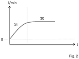
- FIG 2 shows a schematic flow profile 30, 31 of the respiratory gas supply system 1.
- the respiratory gas source 2 is here controlled by the control unit 3 using the flow control module 6 to specify a respiratory gas flow 30 in the range of 0-90 l/min. It can be seen that the flow 30 gradually increases 31 and is finally kept constant at the specified value 30 .
- the flow sensor device 8 determines the current flow and the control unit compares this with the specified flow and regulates the specified flow 30 with a high degree of accuracy of at least +/-5% in the flow range from 5 to 70 l/min.
- the specification is possible in the range from 0-90 l/min, preferably from 0-60 l/min in steps of, for example, 0.5 l/min. If desired by the user, an oxygen admixture of 0-90 l/min, preferably 1-45 l/min, is possible.
- the control unit activates the oxygen source 14.
- the control unit also always activates the heater 16 and the humidifier 13 or the nebulizer 15 for conditioning the breathing gas to a predeterminable temperature and a predeterminable humidity. Temperature and humidity are typically always higher than those of the ambient air. The temperature can be set in the range of 30°- 37°C, for example in 1°C increments.
- FIG 3 shows schematically a pressure curve 40,41... of the system for supplying respiratory gas 1.
- the respiratory gas source 2 is controlled here by the control unit 3 using the pressure control module 4 to specify a respiratory gas pressure 40 in the range of 0-90 mbar. It can be seen that the pressure 40 increases from a PEEP or EPAP level to an IPAP.
- the transition from the PEEP or EPAP level to the IPAP can take place in the form of a predefinable ramp 41 or waveform.
- the transition from IPAP to EPAP can take place in the form of a predefinable ramp 42 or waveform.
- the EPAP pressure can be constant or increase from an initially low EPAP towards the end of expiration. It is also conceivable according to the invention that the EPAP includes at least two different pressure levels.
- the flow sensor device 8 and/or the pressure sensor device determines the current flow and/or pressure and the control unit determines the respiratory phase of the patient from these values and takes this into account at least temporarily when specifying the pressures IPAP and EPAP.
- the control unit compares the pressure with the specified pressure (from memory 5) and regulates the pressure with a high degree of accuracy of at least +/- 5% in the range from 2 to 45 mbar.
- figure 3 also shows that upon user selection 45 or upon an event 45, the control unit sets the pressure at a constant CPAP level.
- the control unit recognizes the event for example from the signals of the flow sensor device 8 and/or the pressure sensor device as breathing pauses or as periodic breathing.
- figure 4 1 schematically shows a flow profile 30 of the respiratory gas supply system 1.
- the respiratory gas source 2 is controlled here by the control unit 3 using the flow control module 6 to specify a respiratory gas flow 30 in the range of 0-90 l/min.
- figure 4 also shows a schematic of a pressure profile 40 of the system for supplying breathing gas 1.
- the breathing gas source 2 is controlled here by the control unit 3 using the pressure control module 4 to specify a breathing gas pressure 40 in the range of 0-90 mbar to EPAP or IPAP or CPAP pressure.
- the control unit 3 alternately activates the flow control module 4 and then the pressure control module 4 .
- the transition from flow control to pressure control or from pressure control to flow control can take place on user selection 49 via user interface 9 or automatically on an event 50 as specified by the control unit or automatically on a predetermined sequence read by the control unit from memory 5 will.
- Such an event 50 can be the change in the time of day.
- the control unit has a clock that switches from day to night mode according to predefinable times.
- the control unit can initiate the change from day to night mode in response to user input, or based on a sensor device that detects the user's sleep.
- the control unit 3 can activate the flow control module, which controls the breathing gas source 2 during the day to specify a breathing gas flow.
- the control unit 3 registers the change in the time of day and activates the pressure control at night to specify a breathing gas pressure with a low inspiratory pressure and a higher expiratory pressure or at a CPAP level.
- the system after 4 is also set up and configured such that the control unit 3 activates the flow module 6 during the day, with the flow module 5 controlling the respiratory gas source 2 to specify a respiratory gas flow and at night to specify at least one respiratory gas pressure level, which is dependent on signals 20 from the pressure sensor device 7 and /or the flow sensor device 8 is modulated when the signals 20 are indicative of periodic breathing or breathing pauses.
- the breathing gas pressure level is modulated such that the pressure settings dampen the periodic breathing or reinforce. If the signals 20 are indicative of breathing pauses, the respiratory gas pressure level is modulated in such a way that the pressure specifications specify a higher pressure difference EPAP ⁇ IPAP or a CPAP.
- the high-flow system for supplying respiratory gas builds up a fresh gas flow of up to 90 l/min through a gas mixer, which means that the flow is higher than in respiratory devices. Due to the high flow, the respiratory gas flows continuously to the patient without impeding their own breathing.
- the system includes a gas mixer (compressed air or ventilator and oxygen), an airway humidifier (which also heats the breathing gas), if necessary a reservoir bag and a PEEP valve.
- the pressure generated by the PEEP valve at the end of expiration is also maintained during inspiration because there is a high respiratory gas flow throughout the respiratory cycle.
- the system reduces high-flow CPAP the risk of pressure inconsistencies under mask CPAP.
- the system after figure 5 is also set up and configured such that the control unit 3 activates the flow module 6, with the flow module 6 controlling the respiratory gas source 2 to specify a definable respiratory gas flow 30 and depending on signals 20 from the pressure sensor device 7 and/or the flow sensor device 8 the pressure 40 increased until the specified breathing gas flow 30 is reached.
- the system is also set up so that the flow sensor device 8 monitors the respiratory gas flow, the flow module 6 using the signals from the flow sensor device 8 to check whether the specified respiratory gas flow has been reached and the pressure sensor device to monitor the respiratory gas pressure, the flow module 6 using the signals of the pressure sensor device checks whether a specified maximum respiratory gas pressure 43 has been reached and flow module 6 does not further increase the maximum respiratory gas pressure until the specified respiratory gas flow 30 has been reached.
- the current flow 33 can remain below the specification 30 for a few seconds or minutes and, if necessary, increase only slowly.
- the system after 6 is also set up and configured such that the control unit 3 activates the flow module 6, with the flow module 6 using the respiratory gas source 2 to specify a predeterminable Respiratory gas flow 30 controls and depending on signals 20 of the pressure sensor device 7 and / or the flow sensor device 8 increases the pressure 40 until the specified respiratory gas flow 30 is reached.
- the system is also set up so that the flow sensor device 8 monitors the respiratory gas flow, with the flow module 6 or the control unit 3 using the signals from the flow sensor device 8 checking whether the specified respiratory gas flow has been reached, and with the pressure sensor device monitoring the respiratory gas pressure, with the flow - Module 6 or the control unit 3 uses the signals from the pressure sensor device to check whether a specified maximum respiratory gas pressure 43 has been reached and whether the flow module 6 or the control unit 3 does not further increase the maximum respiratory gas pressure if the specified respiratory gas flow 30 is not reached. The maximum breathing gas pressure 43 is not increased any further even if the current breathing gas flow 33 does not reach the specification 30 .
Landscapes
- Health & Medical Sciences (AREA)
- Pulmonology (AREA)
- Heart & Thoracic Surgery (AREA)
- Engineering & Computer Science (AREA)
- Anesthesiology (AREA)
- Biomedical Technology (AREA)
- Emergency Medicine (AREA)
- Hematology (AREA)
- Life Sciences & Earth Sciences (AREA)
- Animal Behavior & Ethology (AREA)
- General Health & Medical Sciences (AREA)
- Public Health (AREA)
- Veterinary Medicine (AREA)
- Otolaryngology (AREA)
- Respiratory Apparatuses And Protective Means (AREA)
Abstract
Description
- Die Erfindung betrifft ein System zur Atemgasversorgung umfassend eine Atemgasquelle, eine Steuereinheit, ein Drucksteuermodul und ein Flusssteuermodul, wobei ebenfalls eine Drucksensoreinrichtung und eine Flusssensoreinrichtung und eine Anwenderschnittstelle zur Vorgabe von Parametern der Atemgasversorgung oder zum Austausch von Daten vorgesehen sind. Die Steuereinheit aktiviert alternierend das Drucksteuermodul und das Flusssteuermodul, wobei das Drucksteuermodul die Atemgasquelle zur Vorgabe eines Atemgasdrucks ansteuert und wobei das Flusssteuermodul die Atemgasquelle zur Vorgabe eines Atemgasflusses ansteuert.
- Bei der druckunterstützten Beatmung wird der Atemantrieb des Patienten - mehr oder weniger - berücksichtigt. Sie ist im Gegensatz zur volumenkontrollierten Beatmung schonender, da hier keine hohen Spitzendrücke entstehen können. Wenn der Patient einatmet wird der Atmungsvorgang unterstützt und die Atemarbeit dadurch erleichtert. Gekennzeichnet ist die druckunterstützten Beatmung durch ein unteres Druckniveau und ein oberes Druckniveau. Diese beiden Drücke sind variabel einstellbar. Aus der Menge an Luft die bis Erreichen des oberen Druckes abgegeben wurde, ergibt sich das Atemzugvolumen. Hat der Patient längere Atempausen kann er, mittels einer Backup/Hintergrund-Frequenz, kontrolliert zwischenbeatmet werden. Die Triggerung der Inspiration und Exspiration kann flussgesteuert oder druckgesteuert oder zeitgesteuert erfolgen
- Bei einer CPAP-Therapie wird die Spontanatmung eines Patienten mit einem kontinuierlichen Überdruck unterstützt, um Atemstillstände zu vermeiden.
- Bei dieser Beatmungsform wird dem Patienten, innerhalb einer vorgegebenen Inspirationszeit, ein festgelegtes Atemvolumen appliziert. Das Atemminutenvolumen errechnet sich aus Atemzugvolumen und der Atemfrequenz. Bei dieser Beatmungsform können hohe Spitzendrücke entstehen, da das Beatmungsgerät in erster Linie versucht das eingestellte Volumen zu applizieren. Um dieses Risiko zu verhindern, muss ein Maximaldruck als Alarmgrenze hinterlegt werden.
- Mischformen der vorgenannten Beatmungsmodi versuchen die "die Vorteile" der beiden Beatmungsformen (Volumen- und Druckbeatmung) vereinen.
Es ist noch kein System zur Atemgasversorgung bzw. noch keine Atemgasquelle bekannt, die einen hohen Fluss vorgibt und alternierend dazu eine druckunterstützte oder druckkontrollierte Beatmung. - Die Erfindung betrifft daher ein System zur Atemgasversorgung umfassend eine Atemgasquelle, eine Steuereinheit, einen Speicher, ein Drucksteuermodul und ein Flusssteuermodul, eine Drucksensoreinrichtung und eine Flusssensoreinrichtung und eine Anwenderschnittstelle zur Vorgabe von Parametern der Atemgasversorgung oder zum Austausch von Daten, mit einem Atemgasschlauch und einem Patienteninterface, wobei das System zusätzlich zumindest einen Anfeuchter und/oder eine Sauerstoffquelle und/oder einen Vernebler und/oder eine Heizung aufweist dadurch gekennzeichnet, dass die Steuereinheit alternierend das Drucksteuermodul oder das Flusssteuermodul aktiviert, wobei das Drucksteuermodul die Atemgasquelle zur Vorgabe eines Atemgasdrucks ansteuert und wobei das Flusssteuermodul die Atemgasquelle zur Vorgabe eines Atemgasflusses ansteuert, dadurch gekennzeichnet, dass das Drucksteuermodul die Atemgasquelle zur Vorgabe eines niedrigen exspiratorischen Druckes und eines höheren inspiratorischen Druckes ansteuert.
- In manchen Ausführungsformen umfasst System zur Atemgasversorgung eine Atemgasquelle, eine Steuereinheit, einen Speicher, ein Drucksteuermodul und ein Flusssteuermodul, eine Drucksensoreinrichtung und eine Flusssensoreinrichtung und eine Anwenderschnittstelle zur Vorgabe von Parametern der Atemgasversorgung oder zum Austausch von Daten, mit einem Atemgasschlauch und einem Patienteninterface, wobei das System zusätzlich zumindest einen Anfeuchter und/oder eine Sauerstoffquelle und/oder einen Vernebler und/oder eine Heizung aufweist dadurch gekennzeichnet, dass die Steuereinheit alternierend das Drucksteuermodul oder das Flusssteuermodul aktiviert, wobei das Drucksteuermodul die Atemgasquelle zur Vorgabe eines Atemgasdrucks ansteuert und wobei das Flusssteuermodul die Atemgasquelle zur Vorgabe eines Atemgasflusses ansteuert.
- Das System ist auch dadurch gekennzeichnet, dass die Steuereinheit bei Aktivierung des Flusssteuermoduls 6 zusätzlich den Anfeuchter 13 und die Heizung 16 zur Erwärmung und Anfeuchtung des Atemgases aktiviert.
- Das System ist alternativ oder ergänzend dadurch gekennzeichnet, dass die Steuereinheit bei Aktivierung des Flusssteuermoduls 6 zusätzlich den Anfeuchter 13 und die Heizung 16 und die Sauerstoffquelle 14 zur Konditionierung des Atemgases aktiviert.
- Das System ist alternativ oder ergänzend dadurch gekennzeichnet, dass das Flusssteuermodul 6 die Atemgasquelle 2 zur Vorgabe eines Atemgasflusses im Bereich von 0 - 90 l/min, bevorzugt 1 - 80 l/min, besonders bevorzugt 2-60 l/min ansteuert.
- Das System ist alternativ oder ergänzend dadurch gekennzeichnet, dass das Drucksteuermodul 4 die Atemgasquelle 2 zur Vorgabe eines Atemgasdruckes im Bereich von 0 - 90 mbar, bevorzugt 1 - 80 mbar, besonders bevorzugt 2 - 60 mbar ansteuert.
- Das System ist alternativ oder ergänzend dadurch gekennzeichnet, dass das Drucksteuermodul 4 die Atemgasquelle zur Vorgabe eines niedrigen exspiratorischen Druckes und eines höheren inspiratorischen Druckes ansteuert.
- Das System ist alternativ oder ergänzend dadurch gekennzeichnet, dass das Drucksteuermodul 4 die Atemgasquelle zur Vorgabe eines konstanten Druckes ansteuert.
- Das System ist alternativ oder ergänzend dadurch gekennzeichnet, dass das Drucksteuermodul die Atemgasquelle alternierend zur Vorgabe eines niedrigen exspiratorischen Druckes und eines höheren inspiratorischen Druckes und eines konstanten Druckes ansteuert.
- Das System ist alternativ oder ergänzend dadurch gekennzeichnet, dass das Drucksteuermodul die Atemgasquelle zur Vorgabe eines konstanten inspiratorischen Druckes ansteuert.
- Das System ist alternativ oder ergänzend dadurch gekennzeichnet, dass das Drucksteuermodul die Atemgasquelle zur Vorgabe eines inspiratorischen Druckes mit einer vorgebbaren Druckwellenform ansteuert.
- Das System ist alternativ oder ergänzend dadurch gekennzeichnet, dass das Drucksteuermodul die Atemgasquelle zur Vorgabe eines inspiratorischen Druckes mit zwei unterschiedlichen inspiratorischen Druckniveaus ansteuert.
- Das System ist alternativ oder ergänzend dadurch gekennzeichnet, dass das Drucksteuermodul die Atemgasquelle zur Vorgabe eines konstanten exspiratorischen Druckes ansteuert.
- Das System ist alternativ oder ergänzend dadurch gekennzeichnet, dass das Drucksteuermodul die Atemgasquelle zur Vorgabe eines exspiratorischen Druckes mit einer vorgebbaren Druckwellenform ansteuert.
- Das System ist alternativ oder ergänzend dadurch gekennzeichnet, dass das Drucksteuermodul die Atemgasquelle zur Vorgabe eines exspiratorischen Druckes mit zwei unterschiedlichen exspiratorischen Druckniveaus ansteuert, wobei der Druck ausgehend von einem niedrigen exspiratorischen Niveau auf ein erhöhtes exspiratorisches Niveau angehoben wird.
- Das System ist alternativ oder ergänzend dadurch gekennzeichnet, dass das Drucksteuermodul die Atemgasquelle zur Vorgabe eines exspiratorischen Druckes und eines rampenförmigen Druckanstieges auf ein inspiratorisches Druckniveau ansteuert.
- Das System ist alternativ oder ergänzend dadurch gekennzeichnet, dass das Drucksteuermodul die Atemgasquelle zur Vorgabe eines inspiratorischen Druckes und eines rampenförmigen Druckabfalls auf ein exspiratorisches Druckniveau ansteuert.
- Das System ist alternativ oder ergänzend dadurch gekennzeichnet, dass die Steuereinheit zur Erkennung von Atmungsbemühungen aus dem Drucksignal und/oder aus dem Flusssignal der Drucksensoreinrichtung und/oder der Flusssensoreinrichtung ausgebildet ist.
- Das System ist alternativ oder ergänzend dadurch gekennzeichnet, dass die Atemgasquelle ausgebildet ist als Elektromotor mit Lüfterrad.
- Das System ist alternativ oder ergänzend dadurch gekennzeichnet, dass das Patienteninterface als Nasenkanüle oder Flusskanüle oder Maske oder als Tracheostomieanschluss ausgebildet ist.
- Das System ist alternativ oder ergänzend dadurch gekennzeichnet, dass bei Aktivierung des Flusssteuermoduls als Patienteninterface eine Nasenkanüle oder Flusskanüle oder als ein Tracheostomieanschluss verwendet ist.
- Das System ist alternativ oder ergänzend dadurch gekennzeichnet, dass bei Aktivierung des Flusssteuermoduls auch ein interner oder externer Anfeuchter aktiviert ist.
- Das System ist alternativ oder ergänzend dadurch gekennzeichnet, dass die Steuereinheit die Atemgasquelle tagsüber zur Vorgabe eines Atemgasflusses ansteuert und nachts zur Vorgabe eines Atemgasdruckes mit niedrigem inspiratorischem Druck und höherem exspiratorischem Druck.
- Das System ist alternativ oder ergänzend dadurch gekennzeichnet, dass die Steuereinheit die Atemgasquelle tagsüber zur Vorgabe eines Atemgasflusses ansteuert und nachts zur Vorgabe zumindest eines Atemgasdruckniveaus, welches in Abhängigkeit von Signalen der Drucksensoreinrichtung und/oder der Flusssensoreinrichtung moduliert wird, wenn die Signale indikativ sind für periodische Atmung oder Atemaussetzer.
- Das System ist alternativ oder ergänzend dadurch gekennzeichnet, dass die Steuereinheit die Atemgasquelle tagsüber zur Vorgabe eines Atemgasflusses ansteuert und nachts zur Vorgabe zumindest eines Atemgasdruckniveaus, welches in Abhängigkeit von Signalen der Drucksensoreinrichtung und/oder der Flusssensoreinrichtung moduliert wird, wenn die Signale indikativ sind für periodische Atmung oder Atemaussetzer.
- Das System ist alternativ oder ergänzend dadurch gekennzeichnet, dass die Steuereinheit 3 die Atemgasquelle 2 zur Vorgabe eines vorgebbaren Atemgasflusses ansteuert und in Abhängigkeit von Signalen 20 der Drucksensoreinrichtung 7 und/oder der Flusssensoreinrichtung 8 den Druck erhöht, bis der vorgegebene Atemgasfluss erreicht ist.
- Das System ist alternativ oder ergänzend dadurch gekennzeichnet, dass die Steuereinheit 3 die Atemgasquelle 2 zur Vorgabe eines vorgebbaren Atemgasflusses ansteuert, wobei die Flusssensoreinrichtung 8 den Atemgasfluss überwacht, wobei die Steuereinheit anhand der Signale der Flusssensoreinrichtung 8 prüft, ob der vorgegebene Atemgasfluss erreicht ist, wobei die Drucksensoreinrichtung den Atemgasdruck überwacht, wobei die Steuereinheit anhand der Signale der Drucksensoreinrichtung prüft, ob ein vorgegebener maximale Atemgasdruck erreicht ist und die Steuereinheit den maximalen Atemgasdruck nicht weiter erhöht, wenn der vorgegebene Atemgasfluss nicht erreicht ist.
- Das System ist alternativ oder ergänzend dadurch gekennzeichnet, dass die Steuereinheit das Flusssteuermodul 6 aktiviert und dabei versucht, den eingestellten Fluss zu erzeugen und dabei auch den dazu benötigten Druck bestimmt, stößt dieser an eine vorgegebene Schwelle für einen Zeitraum von, typischerweise ca. 0,001 - 10 Sekunden, so schaltet die Steuereinheit auf Drucksteuerung 4 und hält einen vorgegebenen maximal erlaubten Druck, auch wenn der Fluss unter der eingestellten Vorgabe liegt, wenn der eingestellte Fluss wieder erreicht oder überschritten wird, für einen Zeitraum von, typischerweise ca. 0,001 - 10 Sekunden, dann schaltet die Steuereinheit wieder zurück auf die Fluss-Steuerung 6.
- Das System dient auch zum Mischen von Umgebungsluft (unter Fluss) und Sauerstoff (O2).
- Die Menge des zugeführten Atemgases wird über einen Flussmesser (1-90 l/min) geregelt. Zusätzlich wird über einen Sauerstoffmischer die Applikation der gewünschten Sauerstoffmenge (bis zu 100%) eingestellt.
- Das Atemgas wird dem Patient über eine spezielle Nasenbrille oder Kanüle zugeführt, die zur Unterstützung der Spontanatmung dient.
- Aufgrund des hohen Gasflusses entsteht ein positiver Atemwegsdruck (PEEP), der von der Höhe des Gasflusses abhängig ist. Durch den hohen Gasfluss wird Kohlendioxid aus dem Nasenrachenraum ausgewaschen.
- Durch den hohen Gasfluss wird eine frühere Extubation (Entfernen des Beatmungsschlauchs) ermöglicht.
Der hohe Gasfluss erleichtert die Atemarbeit. Der hohe Gasfluss minimiert die Atemanstrengung. Die Atemfrequenz wird durch hohe Flussraten reduziert. - Die Erfindung betrifft auch eine Atemgasquelle 2 die aufweist, eine Steuereinheit 3, einen Speicher 5, ein Drucksteuermodul 4 und ein Flusssteuermodul 6, eine Drucksensoreinrichtung 7 und eine Flusssensoreinrichtung 8 und eine Anwenderschnittstelle 9 zur Vorgabe von Parametern 10 der Atemgasversorgung oder zum Austausch von Daten, mit einem Atemgasschlauch 11 und einem Patienteninterface 12, wobei das System 1 zusätzlich zumindest einen Anfeuchter 13 und/oder eine Sauerstoffquelle 14 und/oder einen Vernebler 15 und/oder eine Heizung 16 aufweist dadurch gekennzeichnet, dass die Steuereinheit 3 alternierend das Drucksteuermodul 4 oder das Flusssteuermodul 6 aktiviert, wobei das Drucksteuermodul 4 die Atemgasquelle 2 zur Vorgabe eines Atemgasdrucks ansteuert und wobei das Flusssteuermodul 6 die Atemgasquelle zur Vorgabe eines Atemgasflusses ansteuert.
-
Figur 1 zeigt schematisch das System zur Atemgasversorgung 1 umfassend eine Atemgasquelle 2, eine Steuereinheit 3, ein Drucksteuermodul 4, ein Flusssteuermodul 6 und einen Speicher 5, wobei ebenfalls eine Drucksensoreinrichtung 7 und eine Flusssensoreinrichtung 8 und eine Anwenderschnittstelle 9 zur Vorgabe von Parametern 10 der Atemgasversorgung oder zum Austausch von Daten umfasst sind. Das System weist einen Atemgasschlauch 11 und ein Patienteninterface 12 auf, wobei das System 1 zusätzlich zumindest einen Anfeuchter 13 und/oder eine Sauerstoffquelle 14 und/oder einen Vernebler 15 und/oder eine Heizung 16 aufweist. Die Steuereinheit 3 aktiviert alternierend das Drucksteuermodul 4 und das Flusssteuermodul 6, wobei das Drucksteuermodul 4 die Atemgasquelle 2 zur Vorgabe eines Atemgasdrucks im Bereich von 0 - 90 mbar ansteuert und wobei das Flusssteuermodul 6 die Atemgasquelle zur Vorgabe eines Atemgasflusses im Bereich von 0 - 90 l/min ansteuert. - Die Steuereinheit 3 ist eingerichtet und ausgebildet die Atemgasquelle 2, unter Verwendung des Drucksteuermoduls 4 oder des Flusssteuermoduls 6, zur automatischen Vorgabe eines Atemgasdruckes und/oder eines Atemgasflusses anzusteuern.
- Die Steuereinheit 3 ist eingerichtet und ausgebildet bei Aktivierung des Flusssteuermoduls 4 zusätzlich zumindest zeitweise den Anfeuchter 13 oder den Vernebler und die Heizung 16 zur Erwärmung und Anfeuchtung des Atemgases zu aktivieren.
- Bei Aktivierung des Flusssteuermoduls 4 kann die Steuereinheit 3 zusätzlich eine Sauerstoffquelle 14 und/oder einen Vernebler 15 zur Konditionierung des Atemgases aktivieren.
- Der Atemgasschlauch 11 und/oder der Anfeuchter 13 und/oder der Vernebler 15 weisen jeweils eine Heizung 16 auf. Alternativ weist zumindest der Atemgasschlauch 11 und/oder der Anfeuchter 13 und/oder der Vernebler 15 eine Heizung 16 auf.
- Die Steuereinheit ist zur Erkennung von Atmungsbemühungen aus dem Drucksignal und/oder aus dem Flusssignal der Drucksensoreinrichtung und/oder der Flusssensoreinrichtung eingerichtet und ausgebildet. Die Steuereinheit ist zudem zur Erkennung von periodischer Atmung oder Atemaussetzern aus dem Drucksignal und/oder aus dem Flusssignal der Drucksensoreinrichtung und/oder der Flusssensoreinrichtung eingerichtet und ausgebildet.
- Die Anwenderschnittstelle 9 zur Vorgabe von Parametern 10 der Atemgasversorgung oder zum Austausch von Daten ist beispielsweise ausgebildet als ein Touchscreen. Alternativ oder ergänzend können auch ein Display und Eingabetasten vorgesehen sein. Ergänzend weist die Anwenderschnittstelle 9 zumindest eine Schnittstelle (USB, Bluetooth, WLAN...) zur Verbindung mit externen Geräten oder einem Netzwerk auf, um Daten auszutauschen. Vorgegebene Parameter werden im Speicher abrufbar abgelegt.
- Die Atemgasquelle 2 ist beispielsweise ausgebildet als Elektromotor mit Lüfterrad oder als Druckgasquelle. Das Patienteninterface 12 ist ausgebildet als Nasenkanüle oder Maske oder als Tracheostomieanschluss ausgebildet ist.
- Das System ist ausgebildet und eingerichtet, dass bei Aktivierung des Flusssteuermoduls als Patienteninterface eine Nasenkanüle oder als ein Tracheostomieanschluss verwendet ist und bei Aktivierung des Flusssteuermoduls auch ein interner oder externer Anfeuchter aktiviert und verwendet ist.
- Das System ist beispielsweise ausgebildet und eingerichtet, dass bei Aktivierung des Flusssteuermoduls der interne Befeuchter deaktiviert wird. Stattdessen wird ein externer Anfeuchter verwendet oder aktiviert, der Leistungsstärker ist.
- Das System ist beispielsweise ausgebildet und eingerichtet, dass bei Aktivierung des Flusssteuermoduls eine interne Sauerstoffquelle 14 deaktiviert wird. Stattdessen wird eine externe Sauerstoffquelle verwendet.
- Das System ist beispielsweise ausgebildet und eingerichtet, dass bei Aktivierung des Flusssteuermoduls eine Sauerstoffbeimischung, über eine interne oder externe Sauerstoffquelle, bis 90 l/min erfolgt.
- Das System ist beispielsweise ausgebildet und eingerichtet, dass bei Aktivierung des Flusssteuermoduls die Steuereinheit unter Berücksichtigung der Signale der Fluss- und/oder Drucksensoreinrichtung, eine Sauerstoffquelle zur Sauerstoffbeimischung aktiviert, die Atemphasenabhängig moduliert wird. Beispielsweise ist daran gedacht die Sauerstoffbeimischung so zu steuern, dass in Phasen der Inspiration dem Patienten mehr Sauerstoff zur Verfügung steht als zur Exspiration.
- Das System ist beispielsweise ausgebildet und eingerichtet, dass ein Pulsoximeter 17 oder ein Co2-Messgerät 18 adaptiert werden kann, welches dann mit dem System kommuniziert und/oder von ihm mit Energie versorgt wird. Über die Messwerte dieser Geräte kann der Anwender - oder ein automatischer Algorithmus - die richtige Flussrate und die richtige Sauerstoff-Beimischung einstellen. Beispielsweise berücksichtigt die Steuereinheit Messwerte des Pulsoximeters 17 und/oder des Co2-Messgerätes 18 bei der Aktivierung / Steuerung der Sauerstoffquelle und/oder bei der Aktivierung / Steuerung des Flusssteuermoduls 6.
- Erfindungsgemäß ist daran gedacht, dass der Anwender über die Anwenderschnittstelle eine Vorgabe an die Steuereinheit 3 eingibt das Drucksteuermodul oder das Flusssteuermodul 6 zu aktivieren. Die Vorgabe kann auch im Speicher abgelegt sein und von der Steuereinheit ausgelesen werden. Erfindungsgemäß ist auch daran gedacht, dass die Steuereinheit 3 selbststätig anhand im Speicher abgelegter Informationen das Modul 4 oder 6 wählt und unter Vorgabe der Parameter (Druckwerte, Flusswerte ...) ansteuert.
- Erfindungsgemäß ist auch daran gedacht, dass die Steuereinheit 3 anhand einer Zeitvorgabe das Modul 4 oder 6 wählt und unter Vorgabe der Parameter ansteuert.
- Erfindungsgemäß ist auch daran gedacht, dass die Steuereinheit 3 ermittelt welches Patienteninterface adaptiert ist und anhand dieser Information das passende Modul aktiviert. Erfindungsgemäß ist auch daran gedacht, dass die Steuereinheit 3 ermittelt welches Patienteninterface adaptiert ist und abgleicht, ob das Patienteninterface zum aktivierten Modul passt und entweder selbsttätig das passende Modul aktiviert oder einen Alarm aktiviert, um den Anwender auf eine inkompatible Kombination Patienteninterface und Modul hinzuweisen.
- Das System erkennt beispielsweise, ob ein Ventil-Beatmungsschlauch angeschlossen ist oder nicht. Das erkennt es daran, ob es in den Steuerleitungen für das Ventil einen Druck aufbauen bzw. messen kann. Ist ein Ventil-Beatmungsschlauch verwendet, aktiviert die Steuereinheit das Flusssteuermodul 6 nicht.
- Erfindungsgemäß ist auch daran gedacht, dass die Steuereinheit das Flusssteuermodul 6 aktiviert und dabei bestimmt, welche Druckschwankungen im Schlauch durch die Atmung des Patienten ausgelöst werden. Sind diese größer als ein definierter Schwellenwert, ermittelt die Steuereinheit daraus, dass das Patienteninterface zu dicht oder ungeeignet ist. Es ist also beispielsweise eine Maske oder Tracheostomieanschluss adaptiert und keine Nasenkanüle. Es wird dann ein entsprechender Hinweis oder Alarm ausgegeben. Die Steuereinheit könnte das Flusssteuermodul 6 dann auch deaktivieren.
- Erfindungsgemäß ist auch daran gedacht, dass die Steuereinheit das Flusssteuermodul 6 aktiviert und dabei versucht, den eingestellten Fluss zu erzeugen und dabei auch den dazu benötigten Druck bestimmt. Stößt dieser an eine vorgegebene Schwelle für einen Zeitraum von, typischerweise ca. 0,001 - 10 Sekunden, so schaltet die Steuereinheit auf Drucksteuerung 4 und hält einen vorgegebenen maximal erlaubten Druck, auch wenn der Fluss unter der eingestellten Vorgabe liegt. Wenn nun der eingestellte Fluss wieder erreicht oder überschritten wird, für einen Zeitraum von, typischerweise ca. 0,001 - 10 Sekunden, dann schaltet das Gerät wieder zurück auf die Fluss-Steuerung 6.
- Erfindungsgemäß ist auch daran gedacht, dass die Steuereinheit das Flusssteuermodul 6 aktiviert und dabei bestimmt, welche Atemphasen vorliegt. Die Steuereinheit erkennt Schwankungen durch die Atmung und versucht, diese kontinuierlich auszugleichen.
-
Figur 2 zeigt schematisch einen Flussverlauf 30,31 des Systems zur Atemgasversorgung 1. Die Atemgasquelle 2 wird hier von der Steuereinheit 3 unter Verwendung des Flusssteuermoduls 6 zur Vorgabe eines Atemgasflusses 30 im Bereich von 0 - 90 l/min ansteuert. Man erkennt, dass der Fluss 30 allmählich ansteigt 31 und schließlich auf dem vorgegebenen Wert 30 konstant gehalten wird. - Die Flusssensoreinrichtung 8 ermittelt dabei den aktuellen Fluss und die Steuereinheit gleicht diesen mit dem vorgegebenen Fluss ab und regelt den vorgegebenen Fluss 30 mit hoher Genauigkeit von zumindest +/- 5 % im Flussbereich von 5 bis 70 l/min ein. Die Vorgabe ist im Bereich von 0 - 90 l/min, bevorzugt von 0 - 60 l/min in Schritten von beispielsweise 0,5 l/min möglich. Falls vom Anwender gewünscht ist eine Sauerstoffbeimischung von 0-90 l/min, bevorzugt 1 - 45 l/min möglich. Dazu aktiviert die Steuereinheit die Sauerstoffquelle 14. Zudem aktiviert die Steuereinheit, bei Verwendung des Flusssteuermoduls 6, immer die Heizung 16 und den Anfeuchter 13 oder den Vernebler 15 zur Konditionierung des Atemgases auf eine vorgebbare Temperatur und eine vorgebbare Feuchte. Temperatur und Feuchte liegen typischerweise immer über derjenigen der Umgebungsluft. Die Temperatur ist im Bereich von 30°- 37 °C, in beispielsweise 1°C-Schritten einstellbar.
-
Figur 3 zeigt schematisch einen Druckverlauf 40,41... des Systems zur Atemgasversorgung 1. Die Atemgasquelle 2 wird hier von der Steuereinheit 3 unter Verwendung des Drucksteuermoduls 4 zur Vorgabe eines Atemgasdruckes 40 im Bereich von 0 - 90 mbar ansteuert. Man erkennt, dass der Druck 40 von einem PEEP oder EPAP Niveau ansteigt auf einen IPAP. - Der Übergang vom PEEP oder EPAP Niveau auf den IPAP kann in Form einer vorgebaren Rampe 41 oder Wellenform erfolgen. Ebenso kann der Übergang vom IPAP auf den EPAP in Form einer vorgebaren Rampe 42 oder Wellenform erfolgen. Der EPAP Druck kann konstant sein oder von einem initial geringen EPAP zum Ende der Exspiration ansteigen. Es ist erfindungsgemäß auch denkbar, dass der EPAP zumindest zwei unterschiedliche Druckniveaus umfasst.
- Die Flusssensoreinrichtung 8 und/oder die Drucksensoreinrichtung ermittelt dabei den aktuellen Fluss und/oder Druck und die Steuereinheit ermittelt aus diesen Werten die Atemphase des Patienten und berücksichtigt diese zumindest zeitweise bei der Vorgabe der Drücke IPAP und EPAP. Die Steuereinheit gleicht den Druck mit dem vorgegebenen Druck (aus dem Speicher 5) ab und regelt den Druck mit hoher Genauigkeit von zumindest +/- 5 % im Bereich von 2 bis 45 mbar ein.
-
Figur 3 zeigt zudem, dass auf Anwenderauswahl 45 oder auf ein Ereignis 45 hin die Steuereinheit den Druck auf einem konstanten CPAP Niveau vorgibt. Das Ereignis erkennt die Steuereinheit beispielsweise aus den Signalen der Flusssensoreinrichtung 8 und/oder der Drucksensoreinrichtung als Atemaussetzer oder als periodische Atmung. -
Figur 4 zeigt schematisch einen Flussverlauf 30 des Systems zur Atemgasversorgung 1. Die Atemgasquelle 2 wird hier von der Steuereinheit 3 unter Verwendung des Flusssteuermoduls 6 zur Vorgabe eines Atemgasflusses 30 im Bereich von 0 - 90 l/min angesteuert.Figur 4 zeigt zudem schematisch einen Druckverlauf 40 des Systems zur Atemgasversorgung 1. Die Atemgasquelle 2 wird hier von der Steuereinheit 3 unter Verwendung des Drucksteuermoduls 4 zur Vorgabe eines Atemgasdruckes 40 im Bereich von 0 - 90 mbar auf EPAP oder IPAP oder CPAP-Druck angesteuert. AusFigur 4 ist zudem ersichtlich, dass die Steuereinheit 3 alternierend das Flusssteuermodul 4 und dann das Drucksteuermodul 4 aktiviert. Der Übergang von der Flusssteuerung zur Drucksteuerung oder von der Drucksteuerung zur Flusssteuerung kann auf Anwenderauswahl 49 hin über die Anwenderschnittstelle 9 erfolgen oder automatisch auf ein Ereignis 50 hin unter Vorgabe der Steuereinheit oder automatisch auf einen vorbestimmen Ablauf hin der von der Steuereinheit aus dem Speicher 5 gelesen wird. Ein solches Ereignis 50 kann der Wechsel der Tageszeit sein. Die Steuereinheit weist dazu eine Uhr auf, die entsprechend vorgebbarer Zeitpunkte vom Tag- auf den Nacht-Modus umschaltet. Die Steuereinheit kann den Wechsel vom Tag- auf den Nacht-Modus auf eine Anwendereingabe hin, einleiten oder aufgrund einer Sensoreinrichtung, die den Schlaf des Anwenders feststellt. Die Steuereinheit 3 kann das Flusssteuermodul aktivieren, wobei diese die Atemgasquelle 2 tagsüber zur Vorgabe eines Atemgasflusses ansteuern. Die Steuereinheit 3 registriert den Wechsel der Tageszeit und aktiviert nachts die Drucksteuerung zur Vorgabe eines Atemgasdruckes mit niedrigem inspiratorischem Druck und höherem exspiratorischem Druck oder auf einem CPAP-Niveau. - Das System nach
Fig. 4 ist auch eingerichtet und ausgebildet, dass die Steuereinheit 3 tagsüber das Fluss-Modul 6 aktiviert, wobei das Fluss-Modul 5 die Atemgasquelle 2 zur Vorgabe eines Atemgasflusses ansteuert und nachts zur Vorgabe zumindest eines Atemgasdruckniveaus, welches in Abhängigkeit von Signalen 20 der Drucksensoreinrichtung 7 und/oder der Flusssensoreinrichtung 8 moduliert wird, wenn die Signale 20 indikativ sind für periodische Atmung oder Atemaussetzer. Das Atemgasdruckniveau wird, wenn die Signale 20 indikativ sind für periodische Atmung so moduliert, dass die Druckvorgaben die periodische Atmung dämpfen oder verstärken. Das Atemgasdruckniveau wird, wenn die Signale 20 indikativ sind für Atemaussetzer so moduliert, dass die Druckvorgaben eine höhere Druckdifferenz EPAP - IPAP oder einen CPAP vorgeben. - Das erfindungsgemäße High-Flow System zur Atemgasversorgung baut durch einen Gasmischer einen Frischgasflow von bis zu 90l/min auf, wodurch der Durchfluss höher ist als bei Beatmungs-Geräten. Durch den hohen Fluss strömt das Atemgas kontinuierlich zum Patienten, ohne dass dessen Eigenatmung behindert wird. Zum System gehört ein Gasmischer (Druckluft oder Lüfer und Sauerstoff), ein Atemwegsanfeuchter (der das Atemgas zugleich erwärmt), ggfs. noch ein Reservoirbeutel und ein PEEP-Ventil. Der durch das PEEP-Ventil am Ende der Exspiration erzeugte Druck bleibt auch während der Inspiration erhalten, da während des gesamten Atemzyklus ein hoher Atemgasfluss vorhanden ist. Das System reduziert High-Flow-CPAP die Gefahr von Druckinkonstanzen unter Masken-CPAP.
- Das System nach
Fig. 5 ist auch eingerichtet und ausgebildet, dass die Steuereinheit 3 das Fluss-Modul 6 aktiviert, wobei das Fluss-Modul 6 die Atemgasquelle 2 zur Vorgabe eines vorgebbaren Atemgasflusses 30 ansteuert und in Abhängigkeit von Signalen 20 der Drucksensoreinrichtung 7 und/oder der Flusssensoreinrichtung 8 den Druck 40 erhöht, bis der vorgegebene Atemgasfluss 30 erreicht ist. Das System ist auch eingerichtet, dass die Flusssensoreinrichtung 8 dabei den Atemgasfluss überwacht, wobei das Fluss-Modul 6 anhand der Signale der Flusssensoreinrichtung 8 prüft, ob der vorgegebene Atemgasfluss erreicht ist und wobei die Drucksensoreinrichtung den Atemgasdruck überwacht, wobei das Fluss-Modul 6 anhand der Signale der Drucksensoreinrichtung prüft, ob ein vorgegebener maximaler Atemgasdruck 43 erreicht ist und Fluss-Modul 6 den maximalen Atemgasdruck nicht weiter erhöht, bis der vorgegebene Atemgasfluss 30 erreicht ist. Dabei kann der aktuelle Fluss 33 für einige Sekunden oder Minuten unterhalb der Vorgabe 30 bleiben und sich ggfs. nur langsam erhöhen. Wenn der vorgegebene Atemgasfluss 30 erreicht ist kann eine Umschaltung auf das Flusssteuermodul 4 erfolgen. - Das System nach
Fig. 6 ist auch eingerichtet und ausgebildet, dass die Steuereinheit 3 das Fluss-Modul 6 aktiviert, wobei das Fluss-Modul 6 die Atemgasquelle 2 zur Vorgabe eines vorgebbaren Atemgasflusses 30 ansteuert und in Abhängigkeit von Signalen 20 der Drucksensoreinrichtung 7 und/oder der Flusssensoreinrichtung 8 den Druck 40 erhöht, bis der vorgegebene Atemgasfluss 30 erreicht ist. Das System ist auch eingerichtet, dass die Flusssensoreinrichtung 8 dabei den Atemgasfluss überwacht, wobei das Fluss-Modul 6 oder die Steuereinheit 3 anhand der Signale der Flusssensoreinrichtung 8 prüft, ob der vorgegebene Atemgasfluss erreicht ist und wobei die Drucksensoreinrichtung den Atemgasdruck überwacht, wobei das Fluss-Modul 6 oder die Steuereinheit 3 anhand der Signale der Drucksensoreinrichtung prüft, ob ein vorgegebener maximaler Atemgasdruck 43 erreicht ist und das Fluss-Modul 6 oder die Steuereinheit 3 den maximalen Atemgasdruck nicht weiter erhöht, wenn der vorgegebene Atemgasfluss 30 nicht erreicht ist. Der maximale Atemgasdruck 43 wird auch dann nicht weiter erhöht, wenn der aktuelle Atemgasfluss 33 nicht die Vorgabe 30 erreicht.
Claims (17)
- System zur Atemgasversorgung 1 umfassend eine Atemgasquelle 2, eine Steuereinheit 3, einen Speicher 5, ein Drucksteuermodul 4 und ein Flusssteuermodul 6, eine Drucksensoreinrichtung 7 und eine Flusssensoreinrichtung 8 und eine Anwenderschnittstelle 9 zur Vorgabe von Parametern 10 der Atemgasversorgung oder zum Austausch von Daten, mit einem Atemgasschlauch 11 und einem Patienteninterface 12, wobei das System 1 zusätzlich zumindest einen Anfeuchter 13 und/oder eine Sauerstoffquelle 14 und/oder einen Vernebler 15 und/oder eine Heizung 16 aufweist dadurch gekennzeichnet, dass die Steuereinheit 3 alternierend das Drucksteuermodul 4 oder das Flusssteuermodul 6 aktiviert, wobei das Drucksteuermodul 4 die Atemgasquelle 2 zur Vorgabe eines Atemgasdrucks ansteuert und wobei das Flusssteuermodul 6 die Atemgasquelle zur Vorgabe eines Atemgasflusses ansteuert, dadurch gekennzeichnet, dass das Drucksteuermodul 4 die Atemgasquelle 2 zur Vorgabe eines niedrigen exspiratorischen Druckes und eines höheren inspiratorischen Druckes ansteuert.
- System nach Anspruch 1, dadurch gekennzeichnet, dass Drucksteuermodul 4 die Atemgasquelle 2 zur Vorgabe eines rampenförmigen Druckanstieges vom exspiratorischen Druckniveau auf das inspiratorische Druckniveau und zur Vorgabe eines rampenförmigen Druckabfalls vom inspiratorischen Druckniveau auf das exspiratorische Druckniveau ansteuert.
- System nach zumindest einem der vorhergehenden Ansprüche dadurch gekennzeichnet, dass das Drucksteuermodul die Atemgasquelle zur Vorgabe eines inspiratorischen Druckes mit einer vorgebbaren Druckwellenform und eines exspiratorischen Druckes mit einer vorgebbaren Druckwellenform ansteuert.
- System nach zumindest einem der vorhergehenden Ansprüche, dadurch gekennzeichnet, dass das Drucksteuermodul die Atemgasquelle zur Vorgabe eines inspiratorischen Druckes mit zwei unterschiedlichen Druckniveaus und eines exspiratorischen Druckes mit zwei unterschiedlichen Druckniveaus ansteuert.
- System nach zumindest einem der vorhergehenden Ansprüche, dadurch gekennzeichnet, dass die Steuereinheit 3 die Atemgasquelle 2 zur Vorgabe eines vorgebbaren Atemgasflusses ansteuert und in Abhängigkeit von Signalen 20 der Drucksensoreinrichtung 7 und/oder der Flusssensoreinrichtung 8 den Druck erhöht, bis der vorgegebene Atemgasfluss erreicht ist.
- System nach zumindest einem der vorhergehenden Ansprüche dadurch gekennzeichnet, dass die Steuereinheit 3 die Atemgasquelle 2 zur Vorgabe eines vorgebbaren Atemgasflusses ansteuert, wobei die Flusssensoreinrichtung 8 den Atemgasfluss überwacht, wobei die Steuereinheit anhand der Signale der Flusssensoreinrichtung 8 prüft, ob der vorgegebene Atemgasfluss erreicht ist, wobei die Drucksensoreinrichtung den Atemgasdruck überwacht, wobei die Steuereinheit anhand der Signale der Drucksensoreinrichtung prüft, ob ein vorgegebener maximale Atemgasdruck erreicht ist und die Steuereinheit den maximalen Atemgasdruck nicht weiter erhöht, wenn der vorgegebene Atemgasfluss nicht erreicht ist.
- System nach zumindest einem der vorhergehenden Ansprüche, dadurch gekennzeichnet, dass die Menge des zugeführten Atemgases über einen Flussmesser geregelt wird und die Applikation einer gewünschten Sauerstoffmenge über einen Sauerstoffmischer eingestellt wird.
- System nach zumindest einem der vorhergehenden Ansprüche, dadurch gekennzeichnet, dass bei Aktivierung des Flusssteuermoduls eine interne Sauerstoffquelle (14) deaktiviert wird und eine externe Sauerstoffquelle verwendet wird.
- System nach zumindest einem der vorhergehenden Ansprüche, dadurch gekennzeichnet, dass das System so eingerichtet und ausgebildet ist, dass ein Pulsoximeter oder ein CO2-Messgerät adaptierbar ist, wobei das Pulsoximeter oder das CO2-Messgerät mit dem System kommuniziert und/oder vom System mit Energie versorgt wird.
- System nach zumindest einem der vorhergehenden Ansprüche, dadurch gekennzeichnet, dass ein automatischer Algorithmus die Flussrate und Sauerstoffbeimischung über die Messwerte des Pulsoximeters und/oder des CO2-Messgerätes einstellt.
- System nach zumindest einem der vorhergehenden Ansprüche, dadurch gekennzeichnet, dass die Steuereinheit Messwerte des Pulsoximeters und/oder CO-Messgerätes bei der Aktivierung und/oder Steuerung der Sauerstoffquelle und/oder des Flusssteuermoduls berücksichtig.
- System nach zumindest einem der vorhergehenden Ansprüche, dadurch gekennzeichnet, dass die Steuereinheit (3) dazu eingerichtet und ausgebildet ist, zu ermitteln, welches Patienteninterface adaptiert ist und abzugleichen, ob das Patienteninterface zum aktivierten Modul passt.
- System nach zumindest einem der vorhergehenden Ansprüche, dadurch gekennzeichnet, dass die Steuereinheit (3) dazu eingerichtet und ausgebildet ist, selbstständig das zum Patienteninterface passende Modul zu aktivieren oder einen Alarm zu aktivieren, welcher den Anwender auf die inkompatible Kombination von Patienteninterface und Modul hinweist.
- System nach zumindest einem der vorhergehenden Ansprüche, dadurch gekennzeichnet, dass das System dazu eingerichtet und ausgebildet ist, das Druckniveau von einem PEEP oder EPAP Niveau in Form einer vorgebbaren Rampe oder Wellenform auf den IPAP anzuheben und vom IPAP auf ein EPAP in Form einer Rampe oder Wellenform abzusenken.
- System nach zumindest einem der vorhergehenden Ansprüche, dadurch gekennzeichnet, dass das der EPAP zumindest zwei Druckniveaus umfasst und von einem initial geringen EPAP zum Ende der Exspiration ansteigt.
- System nach zumindest einem der vorhergehenden Ansprüche, dadurch gekennzeichnet, dass die Steuereinheit das Flusssteuermodul 6 aktiviert und dabei versucht, den eingestellten Fluss zu erzeugen und dabei auch den dazu benötigten Druck bestimmt.
- System nach zumindest einem der vorhergehenden Ansprüche, dadurch gekennzeichnet, dass die Steuereinheit das Flusssteuermodul 6 aktiviert und dabei bestimmt, welche Atemphasen vorliegt, wobei die Steuereinheit Schwankungen durch die Atmung erkennt und versucht, diese kontinuierlich auszugleichen.
Applications Claiming Priority (2)
| Application Number | Priority Date | Filing Date | Title |
|---|---|---|---|
| DE102017011088 | 2017-11-30 | ||
| EP18000922.7A EP3492131B1 (de) | 2017-11-30 | 2018-11-27 | System zur atemgasversorgung |
Related Parent Applications (2)
| Application Number | Title | Priority Date | Filing Date |
|---|---|---|---|
| EP18000922.7A Division EP3492131B1 (de) | 2017-11-30 | 2018-11-27 | System zur atemgasversorgung |
| EP18000922.7A Division-Into EP3492131B1 (de) | 2017-11-30 | 2018-11-27 | System zur atemgasversorgung |
Publications (2)
| Publication Number | Publication Date |
|---|---|
| EP3950031A1 true EP3950031A1 (de) | 2022-02-09 |
| EP3950031B1 EP3950031B1 (de) | 2024-07-24 |
Family
ID=64556638
Family Applications (2)
| Application Number | Title | Priority Date | Filing Date |
|---|---|---|---|
| EP21020479.8A Active EP3950031B1 (de) | 2017-11-30 | 2018-11-27 | System zur atemgasversorgung |
| EP18000922.7A Active EP3492131B1 (de) | 2017-11-30 | 2018-11-27 | System zur atemgasversorgung |
Family Applications After (1)
| Application Number | Title | Priority Date | Filing Date |
|---|---|---|---|
| EP18000922.7A Active EP3492131B1 (de) | 2017-11-30 | 2018-11-27 | System zur atemgasversorgung |
Country Status (4)
| Country | Link |
|---|---|
| US (1) | US20190160242A1 (de) |
| EP (2) | EP3950031B1 (de) |
| CN (1) | CN109966605A (de) |
| DE (1) | DE102018009288A1 (de) |
Families Citing this family (3)
| Publication number | Priority date | Publication date | Assignee | Title |
|---|---|---|---|---|
| DE102020002278A1 (de) * | 2019-04-24 | 2020-10-29 | Löwenstein Medical Technology S.A. | System zur Atemgasversorgung und Verfahren |
| US12520880B2 (en) | 2021-01-18 | 2026-01-13 | Altria Client Services Llc | Heat-not-burn (HNB) aerosol-generating devices including energy based heater control, and methods of controlling a heater |
| EP4252812A1 (de) * | 2022-03-30 | 2023-10-04 | Koninklijke Philips N.V. | System und verfahren zur nasalen therapie mit hohem durchfluss |
Citations (6)
| Publication number | Priority date | Publication date | Assignee | Title |
|---|---|---|---|---|
| US20050166922A1 (en) * | 2004-02-04 | 2005-08-04 | Sunrise Medical Hhg Inc. | Method for acclimating a CPAP therapy patient to prescribed pressure |
| US20080000475A1 (en) * | 2000-09-25 | 2008-01-03 | Ric Investments, Llc. | Method and apparatus for providing variable positive airway pressure |
| EP2181726A1 (de) * | 2008-10-31 | 2010-05-05 | ResMed Limited | Systeme zur Leitung der Übergänge zwischen Therapiemodi in Verbindung mit der Behandlung und/oder Diagnose von Atemstörungen im Schlaf |
| WO2011068418A1 (en) * | 2009-12-01 | 2011-06-09 | Fisher & Paykel Healthcare Limited | Breathing assistance apparatus |
| US20130133656A1 (en) * | 2010-08-13 | 2013-05-30 | Fisher & Paykel Healthcare Limited | Apparatus and method for providing gases to a user |
| US20170274165A1 (en) * | 2009-11-16 | 2017-09-28 | Resmed Limited | Methods and apparatus for adaptable pressure treatment of sleep disordered breathing |
Family Cites Families (11)
| Publication number | Priority date | Publication date | Assignee | Title |
|---|---|---|---|---|
| US5896857A (en) * | 1996-12-20 | 1999-04-27 | Resmed Limited | Valve for use in a gas delivery system |
| EP1699514B1 (de) * | 2003-12-29 | 2019-09-25 | ResMed Pty Ltd | Mechanische beatmung bei atemstörungen im schlaf |
| DE102006006632B4 (de) * | 2005-02-10 | 2026-05-07 | Löwenstein Medical Technology S.A. | Vorrichtung zur Beatmung sowie Verfahren zur Steuerung eines Beatmungsgerätes |
| US7810497B2 (en) * | 2006-03-20 | 2010-10-12 | Ric Investments, Llc | Ventilatory control system |
| EP2203206A4 (de) * | 2007-09-26 | 2017-12-06 | Breathe Technologies, Inc. | Verfahren und vorrichtungen zur behandlung von schlafapnoe |
| US8905023B2 (en) * | 2007-10-05 | 2014-12-09 | Vapotherm, Inc. | Hyperthermic humidification system |
| EP2282795A4 (de) * | 2008-06-05 | 2016-01-06 | Resmed Ltd | Behandlung von atemwegserkrankungen |
| JP5777637B2 (ja) * | 2010-01-14 | 2015-09-09 | コーニンクレッカ フィリップス エヌ ヴェ | ベースラインからの圧力低下を用いる補助換気装置 |
| US9463293B2 (en) * | 2010-01-14 | 2016-10-11 | Koninklijke Philips N.V. | Servo ventilation using negative pressure support |
| DE102015103894A1 (de) * | 2015-03-17 | 2016-09-22 | Fritz Stephan Gmbh Medizintechnik | Beatmungsgeräte sowie Steuerverfahren für Beatmungsgeräte |
| CN114028666B (zh) * | 2015-03-31 | 2025-10-28 | 费雪派克医疗保健有限公司 | 用于将气体供应至气道的用户接口和系统 |
-
2018
- 2018-11-27 EP EP21020479.8A patent/EP3950031B1/de active Active
- 2018-11-27 EP EP18000922.7A patent/EP3492131B1/de active Active
- 2018-11-27 DE DE102018009288.8A patent/DE102018009288A1/de active Pending
- 2018-11-28 US US16/202,260 patent/US20190160242A1/en active Pending
- 2018-11-30 CN CN201811450288.7A patent/CN109966605A/zh active Pending
Patent Citations (6)
| Publication number | Priority date | Publication date | Assignee | Title |
|---|---|---|---|---|
| US20080000475A1 (en) * | 2000-09-25 | 2008-01-03 | Ric Investments, Llc. | Method and apparatus for providing variable positive airway pressure |
| US20050166922A1 (en) * | 2004-02-04 | 2005-08-04 | Sunrise Medical Hhg Inc. | Method for acclimating a CPAP therapy patient to prescribed pressure |
| EP2181726A1 (de) * | 2008-10-31 | 2010-05-05 | ResMed Limited | Systeme zur Leitung der Übergänge zwischen Therapiemodi in Verbindung mit der Behandlung und/oder Diagnose von Atemstörungen im Schlaf |
| US20170274165A1 (en) * | 2009-11-16 | 2017-09-28 | Resmed Limited | Methods and apparatus for adaptable pressure treatment of sleep disordered breathing |
| WO2011068418A1 (en) * | 2009-12-01 | 2011-06-09 | Fisher & Paykel Healthcare Limited | Breathing assistance apparatus |
| US20130133656A1 (en) * | 2010-08-13 | 2013-05-30 | Fisher & Paykel Healthcare Limited | Apparatus and method for providing gases to a user |
Also Published As
| Publication number | Publication date |
|---|---|
| CN109966605A (zh) | 2019-07-05 |
| US20190160242A1 (en) | 2019-05-30 |
| EP3492131A1 (de) | 2019-06-05 |
| EP3950031B1 (de) | 2024-07-24 |
| DE102018009288A1 (de) | 2019-06-06 |
| EP3492131B1 (de) | 2021-12-29 |
Similar Documents
| Publication | Publication Date | Title |
|---|---|---|
| US10729864B2 (en) | Automatic rise time adjustment | |
| EP1175239B1 (de) | Regulierung des ausgeübten drucks bei der unterstützten beatmung | |
| EP3912663B1 (de) | Beatmungsgerät und steuereinheit zur steuerung einer atemgasquelle | |
| US8776792B2 (en) | Methods and systems for volume-targeted minimum pressure-control ventilation | |
| CN114028677B (zh) | 一种呼吸机气压调节监控系统及其应用 | |
| US20140000606A1 (en) | Methods and systems for mimicking fluctuations in delivered flow and/or pressure during ventilation | |
| US20090165795A1 (en) | Method and apparatus for respiratory therapy | |
| US20170274165A1 (en) | Methods and apparatus for adaptable pressure treatment of sleep disordered breathing | |
| JP6574096B2 (ja) | 周期性呼吸を治療するための方法および装置 | |
| EP3492131B1 (de) | System zur atemgasversorgung | |
| DE102009005048A1 (de) | Verfahren und Einrichtung zur automatischen Ermittlung eines inspiratorischen Leckagevolumens bei der maschinellen Beatmung | |
| EP3263164A1 (de) | Beatmungsgerät zur apap-beatmung mit oszillatorischem druck | |
| EP3673942A1 (de) | Drucksteuerung in einer atemwegbehandlungsvorrichtung | |
| EP3061481B1 (de) | Vorrichtung zur volumenbhängigen triggerung der ausatemphase | |
| DE102016008142A1 (de) | Vorrichtung zum Bereitstellen zyklischer Beatmung und Verfahren zum Ermitteln der Parameter einer zyklischen Beatmung | |
| EP3682928B1 (de) | Beatmungsgerät mit adaptiver steuerung der ausatemphase | |
| AU779072B2 (en) | Control of supplied pressure in assisted ventilation | |
| DE102014012902A1 (de) | Verfahren und Vorrichtung zur Therapie periodischer Atmung | |
| AU2008200057A1 (en) | Control of supplied pressure in assisted ventilation | |
| AU2004229010A1 (en) | Control of supplied pressure in assisted ventilation |
Legal Events
| Date | Code | Title | Description |
|---|---|---|---|
| PUAI | Public reference made under article 153(3) epc to a published international application that has entered the european phase |
Free format text: ORIGINAL CODE: 0009012 |
|
| STAA | Information on the status of an ep patent application or granted ep patent |
Free format text: STATUS: REQUEST FOR EXAMINATION WAS MADE |
|
| 17P | Request for examination filed |
Effective date: 20210929 |
|
| AC | Divisional application: reference to earlier application |
Ref document number: 3492131 Country of ref document: EP Kind code of ref document: P |
|
| AK | Designated contracting states |
Kind code of ref document: A1 Designated state(s): AL AT BE BG CH CY CZ DE DK EE ES FI FR GB GR HR HU IE IS IT LI LT LU LV MC MK MT NL NO PL PT RO RS SE SI SK SM TR |
|
| P01 | Opt-out of the competence of the unified patent court (upc) registered |
Effective date: 20230523 |
|
| STAA | Information on the status of an ep patent application or granted ep patent |
Free format text: STATUS: EXAMINATION IS IN PROGRESS |
|
| 17Q | First examination report despatched |
Effective date: 20230809 |
|
| GRAP | Despatch of communication of intention to grant a patent |
Free format text: ORIGINAL CODE: EPIDOSNIGR1 |
|
| STAA | Information on the status of an ep patent application or granted ep patent |
Free format text: STATUS: GRANT OF PATENT IS INTENDED |
|
| RIC1 | Information provided on ipc code assigned before grant |
Ipc: A61M 16/20 20060101ALN20240226BHEP Ipc: A61M 16/16 20060101ALN20240226BHEP Ipc: A61M 16/14 20060101ALN20240226BHEP Ipc: A61M 16/12 20060101ALN20240226BHEP Ipc: A61M 16/04 20060101ALN20240226BHEP Ipc: A61M 16/00 20060101AFI20240226BHEP |
|
| INTG | Intention to grant announced |
Effective date: 20240315 |
|
| GRAS | Grant fee paid |
Free format text: ORIGINAL CODE: EPIDOSNIGR3 |
|
| GRAA | (expected) grant |
Free format text: ORIGINAL CODE: 0009210 |
|
| STAA | Information on the status of an ep patent application or granted ep patent |
Free format text: STATUS: THE PATENT HAS BEEN GRANTED |
|
| AC | Divisional application: reference to earlier application |
Ref document number: 3492131 Country of ref document: EP Kind code of ref document: P |
|
| AK | Designated contracting states |
Kind code of ref document: B1 Designated state(s): AL AT BE BG CH CY CZ DE DK EE ES FI FR GB GR HR HU IE IS IT LI LT LU LV MC MK MT NL NO PL PT RO RS SE SI SK SM TR |
|
| REG | Reference to a national code |
Ref country code: GB Ref legal event code: FG4D Free format text: NOT ENGLISH |
|
| REG | Reference to a national code |
Ref country code: CH Ref legal event code: EP |
|
| REG | Reference to a national code |
Ref country code: DE Ref legal event code: R096 Ref document number: 502018014920 Country of ref document: DE |
|
| REG | Reference to a national code |
Ref country code: IE Ref legal event code: FG4D Free format text: LANGUAGE OF EP DOCUMENT: GERMAN |
|
| REG | Reference to a national code |
Ref country code: NL Ref legal event code: FP |
|
| REG | Reference to a national code |
Ref country code: LT Ref legal event code: MG9D |
|
| PG25 | Lapsed in a contracting state [announced via postgrant information from national office to epo] |
Ref country code: PT Free format text: LAPSE BECAUSE OF FAILURE TO SUBMIT A TRANSLATION OF THE DESCRIPTION OR TO PAY THE FEE WITHIN THE PRESCRIBED TIME-LIMIT Effective date: 20241125 |
|
| PG25 | Lapsed in a contracting state [announced via postgrant information from national office to epo] |
Ref country code: PT Free format text: LAPSE BECAUSE OF FAILURE TO SUBMIT A TRANSLATION OF THE DESCRIPTION OR TO PAY THE FEE WITHIN THE PRESCRIBED TIME-LIMIT Effective date: 20241125 |
|
| PG25 | Lapsed in a contracting state [announced via postgrant information from national office to epo] |
Ref country code: NO Free format text: LAPSE BECAUSE OF FAILURE TO SUBMIT A TRANSLATION OF THE DESCRIPTION OR TO PAY THE FEE WITHIN THE PRESCRIBED TIME-LIMIT Effective date: 20241024 |
|
| PG25 | Lapsed in a contracting state [announced via postgrant information from national office to epo] |
Ref country code: FI Free format text: LAPSE BECAUSE OF FAILURE TO SUBMIT A TRANSLATION OF THE DESCRIPTION OR TO PAY THE FEE WITHIN THE PRESCRIBED TIME-LIMIT Effective date: 20240724 Ref country code: GR Free format text: LAPSE BECAUSE OF FAILURE TO SUBMIT A TRANSLATION OF THE DESCRIPTION OR TO PAY THE FEE WITHIN THE PRESCRIBED TIME-LIMIT Effective date: 20241025 Ref country code: PL Free format text: LAPSE BECAUSE OF FAILURE TO SUBMIT A TRANSLATION OF THE DESCRIPTION OR TO PAY THE FEE WITHIN THE PRESCRIBED TIME-LIMIT Effective date: 20240724 |
|
| PG25 | Lapsed in a contracting state [announced via postgrant information from national office to epo] |
Ref country code: BG Free format text: LAPSE BECAUSE OF FAILURE TO SUBMIT A TRANSLATION OF THE DESCRIPTION OR TO PAY THE FEE WITHIN THE PRESCRIBED TIME-LIMIT Effective date: 20240724 |
|
| PG25 | Lapsed in a contracting state [announced via postgrant information from national office to epo] |
Ref country code: LV Free format text: LAPSE BECAUSE OF FAILURE TO SUBMIT A TRANSLATION OF THE DESCRIPTION OR TO PAY THE FEE WITHIN THE PRESCRIBED TIME-LIMIT Effective date: 20240724 |
|
| PG25 | Lapsed in a contracting state [announced via postgrant information from national office to epo] |
Ref country code: IS Free format text: LAPSE BECAUSE OF FAILURE TO SUBMIT A TRANSLATION OF THE DESCRIPTION OR TO PAY THE FEE WITHIN THE PRESCRIBED TIME-LIMIT Effective date: 20241124 |
|
| PG25 | Lapsed in a contracting state [announced via postgrant information from national office to epo] |
Ref country code: HR Free format text: LAPSE BECAUSE OF FAILURE TO SUBMIT A TRANSLATION OF THE DESCRIPTION OR TO PAY THE FEE WITHIN THE PRESCRIBED TIME-LIMIT Effective date: 20240724 |
|
| PG25 | Lapsed in a contracting state [announced via postgrant information from national office to epo] |
Ref country code: ES Free format text: LAPSE BECAUSE OF FAILURE TO SUBMIT A TRANSLATION OF THE DESCRIPTION OR TO PAY THE FEE WITHIN THE PRESCRIBED TIME-LIMIT Effective date: 20240724 Ref country code: RS Free format text: LAPSE BECAUSE OF FAILURE TO SUBMIT A TRANSLATION OF THE DESCRIPTION OR TO PAY THE FEE WITHIN THE PRESCRIBED TIME-LIMIT Effective date: 20241024 |
|
| PG25 | Lapsed in a contracting state [announced via postgrant information from national office to epo] |
Ref country code: RS Free format text: LAPSE BECAUSE OF FAILURE TO SUBMIT A TRANSLATION OF THE DESCRIPTION OR TO PAY THE FEE WITHIN THE PRESCRIBED TIME-LIMIT Effective date: 20241024 Ref country code: PL Free format text: LAPSE BECAUSE OF FAILURE TO SUBMIT A TRANSLATION OF THE DESCRIPTION OR TO PAY THE FEE WITHIN THE PRESCRIBED TIME-LIMIT Effective date: 20240724 Ref country code: NO Free format text: LAPSE BECAUSE OF FAILURE TO SUBMIT A TRANSLATION OF THE DESCRIPTION OR TO PAY THE FEE WITHIN THE PRESCRIBED TIME-LIMIT Effective date: 20241024 Ref country code: LV Free format text: LAPSE BECAUSE OF FAILURE TO SUBMIT A TRANSLATION OF THE DESCRIPTION OR TO PAY THE FEE WITHIN THE PRESCRIBED TIME-LIMIT Effective date: 20240724 Ref country code: IS Free format text: LAPSE BECAUSE OF FAILURE TO SUBMIT A TRANSLATION OF THE DESCRIPTION OR TO PAY THE FEE WITHIN THE PRESCRIBED TIME-LIMIT Effective date: 20241124 Ref country code: HR Free format text: LAPSE BECAUSE OF FAILURE TO SUBMIT A TRANSLATION OF THE DESCRIPTION OR TO PAY THE FEE WITHIN THE PRESCRIBED TIME-LIMIT Effective date: 20240724 Ref country code: GR Free format text: LAPSE BECAUSE OF FAILURE TO SUBMIT A TRANSLATION OF THE DESCRIPTION OR TO PAY THE FEE WITHIN THE PRESCRIBED TIME-LIMIT Effective date: 20241025 Ref country code: FI Free format text: LAPSE BECAUSE OF FAILURE TO SUBMIT A TRANSLATION OF THE DESCRIPTION OR TO PAY THE FEE WITHIN THE PRESCRIBED TIME-LIMIT Effective date: 20240724 Ref country code: ES Free format text: LAPSE BECAUSE OF FAILURE TO SUBMIT A TRANSLATION OF THE DESCRIPTION OR TO PAY THE FEE WITHIN THE PRESCRIBED TIME-LIMIT Effective date: 20240724 Ref country code: BG Free format text: LAPSE BECAUSE OF FAILURE TO SUBMIT A TRANSLATION OF THE DESCRIPTION OR TO PAY THE FEE WITHIN THE PRESCRIBED TIME-LIMIT Effective date: 20240724 |
|
| PG25 | Lapsed in a contracting state [announced via postgrant information from national office to epo] |
Ref country code: RO Free format text: LAPSE BECAUSE OF FAILURE TO SUBMIT A TRANSLATION OF THE DESCRIPTION OR TO PAY THE FEE WITHIN THE PRESCRIBED TIME-LIMIT Effective date: 20240724 Ref country code: DK Free format text: LAPSE BECAUSE OF FAILURE TO SUBMIT A TRANSLATION OF THE DESCRIPTION OR TO PAY THE FEE WITHIN THE PRESCRIBED TIME-LIMIT Effective date: 20240724 Ref country code: SM Free format text: LAPSE BECAUSE OF FAILURE TO SUBMIT A TRANSLATION OF THE DESCRIPTION OR TO PAY THE FEE WITHIN THE PRESCRIBED TIME-LIMIT Effective date: 20240724 |
|
| PG25 | Lapsed in a contracting state [announced via postgrant information from national office to epo] |
Ref country code: EE Free format text: LAPSE BECAUSE OF FAILURE TO SUBMIT A TRANSLATION OF THE DESCRIPTION OR TO PAY THE FEE WITHIN THE PRESCRIBED TIME-LIMIT Effective date: 20240724 |
|
| PG25 | Lapsed in a contracting state [announced via postgrant information from national office to epo] |
Ref country code: CZ Free format text: LAPSE BECAUSE OF FAILURE TO SUBMIT A TRANSLATION OF THE DESCRIPTION OR TO PAY THE FEE WITHIN THE PRESCRIBED TIME-LIMIT Effective date: 20240724 |
|
| REG | Reference to a national code |
Ref country code: DE Ref legal event code: R097 Ref document number: 502018014920 Country of ref document: DE |
|
| PG25 | Lapsed in a contracting state [announced via postgrant information from national office to epo] |
Ref country code: IT Free format text: LAPSE BECAUSE OF FAILURE TO SUBMIT A TRANSLATION OF THE DESCRIPTION OR TO PAY THE FEE WITHIN THE PRESCRIBED TIME-LIMIT Effective date: 20240724 Ref country code: SK Free format text: LAPSE BECAUSE OF FAILURE TO SUBMIT A TRANSLATION OF THE DESCRIPTION OR TO PAY THE FEE WITHIN THE PRESCRIBED TIME-LIMIT Effective date: 20240724 |
|
| PLBE | No opposition filed within time limit |
Free format text: ORIGINAL CODE: 0009261 |
|
| STAA | Information on the status of an ep patent application or granted ep patent |
Free format text: STATUS: NO OPPOSITION FILED WITHIN TIME LIMIT |
|
| REG | Reference to a national code |
Ref country code: CH Ref legal event code: PL |
|
| 26N | No opposition filed |
Effective date: 20250425 |
|
| PG25 | Lapsed in a contracting state [announced via postgrant information from national office to epo] |
Ref country code: MC Free format text: LAPSE BECAUSE OF FAILURE TO SUBMIT A TRANSLATION OF THE DESCRIPTION OR TO PAY THE FEE WITHIN THE PRESCRIBED TIME-LIMIT Effective date: 20240724 |
|
| PG25 | Lapsed in a contracting state [announced via postgrant information from national office to epo] |
Ref country code: LU Free format text: LAPSE BECAUSE OF NON-PAYMENT OF DUE FEES Effective date: 20241127 |
|
| REG | Reference to a national code |
Ref country code: CH Ref legal event code: PL |
|
| PG25 | Lapsed in a contracting state [announced via postgrant information from national office to epo] |
Ref country code: CH Free format text: LAPSE BECAUSE OF NON-PAYMENT OF DUE FEES Effective date: 20241130 |
|
| REG | Reference to a national code |
Ref country code: BE Ref legal event code: MM Effective date: 20241130 |
|
| PG25 | Lapsed in a contracting state [announced via postgrant information from national office to epo] |
Ref country code: SE Free format text: LAPSE BECAUSE OF FAILURE TO SUBMIT A TRANSLATION OF THE DESCRIPTION OR TO PAY THE FEE WITHIN THE PRESCRIBED TIME-LIMIT Effective date: 20240724 |
|
| PG25 | Lapsed in a contracting state [announced via postgrant information from national office to epo] |
Ref country code: BE Free format text: LAPSE BECAUSE OF NON-PAYMENT OF DUE FEES Effective date: 20241130 |
|
| PG25 | Lapsed in a contracting state [announced via postgrant information from national office to epo] |
Ref country code: IE Free format text: LAPSE BECAUSE OF NON-PAYMENT OF DUE FEES Effective date: 20241127 |
|
| PGFP | Annual fee paid to national office [announced via postgrant information from national office to epo] |
Ref country code: NL Payment date: 20251119 Year of fee payment: 8 |
|
| PGFP | Annual fee paid to national office [announced via postgrant information from national office to epo] |
Ref country code: DE Payment date: 20251118 Year of fee payment: 8 |
|
| PGFP | Annual fee paid to national office [announced via postgrant information from national office to epo] |
Ref country code: GB Payment date: 20251120 Year of fee payment: 8 |
|
| PG25 | Lapsed in a contracting state [announced via postgrant information from national office to epo] |
Ref country code: AT Free format text: LAPSE BECAUSE OF NON-PAYMENT OF DUE FEES Effective date: 20241127 |
|
| PGFP | Annual fee paid to national office [announced via postgrant information from national office to epo] |
Ref country code: FR Payment date: 20251120 Year of fee payment: 8 |
|
| REG | Reference to a national code |
Ref country code: AT Ref legal event code: MM01 Ref document number: 1705722 Country of ref document: AT Kind code of ref document: T Effective date: 20241127 |
|
| PG25 | Lapsed in a contracting state [announced via postgrant information from national office to epo] |
Ref country code: HU Free format text: LAPSE BECAUSE OF FAILURE TO SUBMIT A TRANSLATION OF THE DESCRIPTION OR TO PAY THE FEE WITHIN THE PRESCRIBED TIME-LIMIT; INVALID AB INITIO Effective date: 20181127 |
|
| PG25 | Lapsed in a contracting state [announced via postgrant information from national office to epo] |
Ref country code: CY Free format text: LAPSE BECAUSE OF FAILURE TO SUBMIT A TRANSLATION OF THE DESCRIPTION OR TO PAY THE FEE WITHIN THE PRESCRIBED TIME-LIMIT; INVALID AB INITIO Effective date: 20181127 |
|
| PG25 | Lapsed in a contracting state [announced via postgrant information from national office to epo] |
Ref country code: TR Free format text: LAPSE BECAUSE OF FAILURE TO SUBMIT A TRANSLATION OF THE DESCRIPTION OR TO PAY THE FEE WITHIN THE PRESCRIBED TIME-LIMIT Effective date: 20240724 |
|
| PG25 | Lapsed in a contracting state [announced via postgrant information from national office to epo] |
Ref country code: SI Free format text: LAPSE BECAUSE OF FAILURE TO SUBMIT A TRANSLATION OF THE DESCRIPTION OR TO PAY THE FEE WITHIN THE PRESCRIBED TIME-LIMIT Effective date: 20240724 |
|
| PG25 | Lapsed in a contracting state [announced via postgrant information from national office to epo] |
Ref country code: LT Free format text: LAPSE BECAUSE OF FAILURE TO SUBMIT A TRANSLATION OF THE DESCRIPTION OR TO PAY THE FEE WITHIN THE PRESCRIBED TIME-LIMIT Effective date: 20240724 |