EP3949834A1 - Therapeutic technique using electrical impedance spectroscopy - Google Patents
Therapeutic technique using electrical impedance spectroscopy Download PDFInfo
- Publication number
- EP3949834A1 EP3949834A1 EP21189024.9A EP21189024A EP3949834A1 EP 3949834 A1 EP3949834 A1 EP 3949834A1 EP 21189024 A EP21189024 A EP 21189024A EP 3949834 A1 EP3949834 A1 EP 3949834A1
- Authority
- EP
- European Patent Office
- Prior art keywords
- patient
- therapy
- medical therapy
- sensors
- impedimetric
- Prior art date
- Legal status (The legal status is an assumption and is not a legal conclusion. Google has not performed a legal analysis and makes no representation as to the accuracy of the status listed.)
- Pending
Links
Images




Classifications
-
- A—HUMAN NECESSITIES
- A61—MEDICAL OR VETERINARY SCIENCE; HYGIENE
- A61H—PHYSICAL THERAPY APPARATUS, e.g. DEVICES FOR LOCATING OR STIMULATING REFLEX POINTS IN THE BODY; ARTIFICIAL RESPIRATION; MASSAGE; BATHING DEVICES FOR SPECIAL THERAPEUTIC OR HYGIENIC PURPOSES OR SPECIFIC PARTS OF THE BODY
- A61H31/00—Artificial respiration by a force applied to the chest; Heart stimulation, e.g. heart massage
-
- A—HUMAN NECESSITIES
- A61—MEDICAL OR VETERINARY SCIENCE; HYGIENE
- A61B—DIAGNOSIS; SURGERY; IDENTIFICATION
- A61B5/00—Measuring for diagnostic purposes; Identification of persons
- A61B5/48—Other medical applications
- A61B5/4836—Diagnosis combined with treatment in closed-loop systems or methods
-
- A—HUMAN NECESSITIES
- A61—MEDICAL OR VETERINARY SCIENCE; HYGIENE
- A61B—DIAGNOSIS; SURGERY; IDENTIFICATION
- A61B5/00—Measuring for diagnostic purposes; Identification of persons
- A61B5/05—Detecting, measuring or recording for diagnosis by means of electric currents or magnetic fields; Measuring using microwaves or radio waves
- A61B5/053—Measuring electrical impedance or conductance of a portion of the body
-
- A—HUMAN NECESSITIES
- A61—MEDICAL OR VETERINARY SCIENCE; HYGIENE
- A61B—DIAGNOSIS; SURGERY; IDENTIFICATION
- A61B5/00—Measuring for diagnostic purposes; Identification of persons
- A61B5/05—Detecting, measuring or recording for diagnosis by means of electric currents or magnetic fields; Measuring using microwaves or radio waves
- A61B5/053—Measuring electrical impedance or conductance of a portion of the body
- A61B5/0537—Measuring body composition by impedance, e.g. tissue hydration or fat content
-
- A—HUMAN NECESSITIES
- A61—MEDICAL OR VETERINARY SCIENCE; HYGIENE
- A61B—DIAGNOSIS; SURGERY; IDENTIFICATION
- A61B5/00—Measuring for diagnostic purposes; Identification of persons
- A61B5/08—Measuring devices for evaluating the respiratory organs
-
- A—HUMAN NECESSITIES
- A61—MEDICAL OR VETERINARY SCIENCE; HYGIENE
- A61B—DIAGNOSIS; SURGERY; IDENTIFICATION
- A61B5/00—Measuring for diagnostic purposes; Identification of persons
- A61B5/08—Measuring devices for evaluating the respiratory organs
- A61B5/085—Measuring impedance of respiratory organs or lung elasticity
- A61B5/086—Measuring impedance of respiratory organs or lung elasticity by impedance pneumography
-
- A—HUMAN NECESSITIES
- A61—MEDICAL OR VETERINARY SCIENCE; HYGIENE
- A61B—DIAGNOSIS; SURGERY; IDENTIFICATION
- A61B5/00—Measuring for diagnostic purposes; Identification of persons
- A61B5/68—Arrangements of detecting, measuring or recording means, e.g. sensors, in relation to patient
- A61B5/6801—Arrangements of detecting, measuring or recording means, e.g. sensors, in relation to patient specially adapted to be attached to or worn on the body surface
- A61B5/6802—Sensor mounted on worn items
- A61B5/6804—Garments; Clothes
-
- A—HUMAN NECESSITIES
- A61—MEDICAL OR VETERINARY SCIENCE; HYGIENE
- A61B—DIAGNOSIS; SURGERY; IDENTIFICATION
- A61B5/00—Measuring for diagnostic purposes; Identification of persons
- A61B5/68—Arrangements of detecting, measuring or recording means, e.g. sensors, in relation to patient
- A61B5/6801—Arrangements of detecting, measuring or recording means, e.g. sensors, in relation to patient specially adapted to be attached to or worn on the body surface
- A61B5/6802—Sensor mounted on worn items
- A61B5/6804—Garments; Clothes
- A61B5/6805—Vests, e.g. shirts or gowns
-
- A—HUMAN NECESSITIES
- A61—MEDICAL OR VETERINARY SCIENCE; HYGIENE
- A61H—PHYSICAL THERAPY APPARATUS, e.g. DEVICES FOR LOCATING OR STIMULATING REFLEX POINTS IN THE BODY; ARTIFICIAL RESPIRATION; MASSAGE; BATHING DEVICES FOR SPECIAL THERAPEUTIC OR HYGIENIC PURPOSES OR SPECIFIC PARTS OF THE BODY
- A61H23/00—Percussion or vibration massage, e.g. using supersonic vibration; Suction-vibration massage; Massage with moving diaphragms
- A61H23/006—Percussion or tapping massage
-
- A—HUMAN NECESSITIES
- A61—MEDICAL OR VETERINARY SCIENCE; HYGIENE
- A61H—PHYSICAL THERAPY APPARATUS, e.g. DEVICES FOR LOCATING OR STIMULATING REFLEX POINTS IN THE BODY; ARTIFICIAL RESPIRATION; MASSAGE; BATHING DEVICES FOR SPECIAL THERAPEUTIC OR HYGIENIC PURPOSES OR SPECIFIC PARTS OF THE BODY
- A61H23/00—Percussion or vibration massage, e.g. using supersonic vibration; Suction-vibration massage; Massage with moving diaphragms
- A61H23/02—Percussion or vibration massage, e.g. using supersonic vibration; Suction-vibration massage; Massage with moving diaphragms with electric or magnetic drive
-
- A—HUMAN NECESSITIES
- A61—MEDICAL OR VETERINARY SCIENCE; HYGIENE
- A61H—PHYSICAL THERAPY APPARATUS, e.g. DEVICES FOR LOCATING OR STIMULATING REFLEX POINTS IN THE BODY; ARTIFICIAL RESPIRATION; MASSAGE; BATHING DEVICES FOR SPECIAL THERAPEUTIC OR HYGIENIC PURPOSES OR SPECIFIC PARTS OF THE BODY
- A61H2201/00—Characteristics of apparatus not provided for in the preceding codes
- A61H2201/16—Physical interface with patient
- A61H2201/1602—Physical interface with patient kind of interface, e.g. head rest, knee support or lumbar support
- A61H2201/1619—Thorax
-
- A—HUMAN NECESSITIES
- A61—MEDICAL OR VETERINARY SCIENCE; HYGIENE
- A61H—PHYSICAL THERAPY APPARATUS, e.g. DEVICES FOR LOCATING OR STIMULATING REFLEX POINTS IN THE BODY; ARTIFICIAL RESPIRATION; MASSAGE; BATHING DEVICES FOR SPECIAL THERAPEUTIC OR HYGIENIC PURPOSES OR SPECIFIC PARTS OF THE BODY
- A61H2201/00—Characteristics of apparatus not provided for in the preceding codes
- A61H2201/16—Physical interface with patient
- A61H2201/1602—Physical interface with patient kind of interface, e.g. head rest, knee support or lumbar support
- A61H2201/1619—Thorax
- A61H2201/1621—Holding means therefor
-
- A—HUMAN NECESSITIES
- A61—MEDICAL OR VETERINARY SCIENCE; HYGIENE
- A61H—PHYSICAL THERAPY APPARATUS, e.g. DEVICES FOR LOCATING OR STIMULATING REFLEX POINTS IN THE BODY; ARTIFICIAL RESPIRATION; MASSAGE; BATHING DEVICES FOR SPECIAL THERAPEUTIC OR HYGIENIC PURPOSES OR SPECIFIC PARTS OF THE BODY
- A61H2201/00—Characteristics of apparatus not provided for in the preceding codes
- A61H2201/16—Physical interface with patient
- A61H2201/1602—Physical interface with patient kind of interface, e.g. head rest, knee support or lumbar support
- A61H2201/165—Wearable interfaces
-
- A—HUMAN NECESSITIES
- A61—MEDICAL OR VETERINARY SCIENCE; HYGIENE
- A61H—PHYSICAL THERAPY APPARATUS, e.g. DEVICES FOR LOCATING OR STIMULATING REFLEX POINTS IN THE BODY; ARTIFICIAL RESPIRATION; MASSAGE; BATHING DEVICES FOR SPECIAL THERAPEUTIC OR HYGIENIC PURPOSES OR SPECIFIC PARTS OF THE BODY
- A61H2201/00—Characteristics of apparatus not provided for in the preceding codes
- A61H2201/50—Control means thereof
- A61H2201/5007—Control means thereof computer controlled
-
- A—HUMAN NECESSITIES
- A61—MEDICAL OR VETERINARY SCIENCE; HYGIENE
- A61H—PHYSICAL THERAPY APPARATUS, e.g. DEVICES FOR LOCATING OR STIMULATING REFLEX POINTS IN THE BODY; ARTIFICIAL RESPIRATION; MASSAGE; BATHING DEVICES FOR SPECIAL THERAPEUTIC OR HYGIENIC PURPOSES OR SPECIFIC PARTS OF THE BODY
- A61H2201/00—Characteristics of apparatus not provided for in the preceding codes
- A61H2201/50—Control means thereof
- A61H2201/5007—Control means thereof computer controlled
- A61H2201/501—Control means thereof computer controlled connected to external computer devices or networks
- A61H2201/5012—Control means thereof computer controlled connected to external computer devices or networks using the internet
-
- A—HUMAN NECESSITIES
- A61—MEDICAL OR VETERINARY SCIENCE; HYGIENE
- A61H—PHYSICAL THERAPY APPARATUS, e.g. DEVICES FOR LOCATING OR STIMULATING REFLEX POINTS IN THE BODY; ARTIFICIAL RESPIRATION; MASSAGE; BATHING DEVICES FOR SPECIAL THERAPEUTIC OR HYGIENIC PURPOSES OR SPECIFIC PARTS OF THE BODY
- A61H2201/00—Characteristics of apparatus not provided for in the preceding codes
- A61H2201/50—Control means thereof
- A61H2201/5097—Control means thereof wireless
-
- A—HUMAN NECESSITIES
- A61—MEDICAL OR VETERINARY SCIENCE; HYGIENE
- A61H—PHYSICAL THERAPY APPARATUS, e.g. DEVICES FOR LOCATING OR STIMULATING REFLEX POINTS IN THE BODY; ARTIFICIAL RESPIRATION; MASSAGE; BATHING DEVICES FOR SPECIAL THERAPEUTIC OR HYGIENIC PURPOSES OR SPECIFIC PARTS OF THE BODY
- A61H2205/00—Devices for specific parts of the body
- A61H2205/08—Trunk
- A61H2205/084—Chest
-
- A—HUMAN NECESSITIES
- A61—MEDICAL OR VETERINARY SCIENCE; HYGIENE
- A61H—PHYSICAL THERAPY APPARATUS, e.g. DEVICES FOR LOCATING OR STIMULATING REFLEX POINTS IN THE BODY; ARTIFICIAL RESPIRATION; MASSAGE; BATHING DEVICES FOR SPECIAL THERAPEUTIC OR HYGIENIC PURPOSES OR SPECIFIC PARTS OF THE BODY
- A61H2230/00—Measuring physical parameters of the user
- A61H2230/40—Respiratory characteristics
- A61H2230/405—Respiratory characteristics used as a control parameter for the apparatus
-
- A—HUMAN NECESSITIES
- A61—MEDICAL OR VETERINARY SCIENCE; HYGIENE
- A61H—PHYSICAL THERAPY APPARATUS, e.g. DEVICES FOR LOCATING OR STIMULATING REFLEX POINTS IN THE BODY; ARTIFICIAL RESPIRATION; MASSAGE; BATHING DEVICES FOR SPECIAL THERAPEUTIC OR HYGIENIC PURPOSES OR SPECIFIC PARTS OF THE BODY
- A61H2230/00—Measuring physical parameters of the user
- A61H2230/65—Impedance, e.g. skin conductivity; capacitance, e.g. galvanic skin response [GSR]
- A61H2230/655—Impedance, e.g. skin conductivity; capacitance, e.g. galvanic skin response [GSR] used as a control parameter for the apparatus
-
- A—HUMAN NECESSITIES
- A61—MEDICAL OR VETERINARY SCIENCE; HYGIENE
- A61H—PHYSICAL THERAPY APPARATUS, e.g. DEVICES FOR LOCATING OR STIMULATING REFLEX POINTS IN THE BODY; ARTIFICIAL RESPIRATION; MASSAGE; BATHING DEVICES FOR SPECIAL THERAPEUTIC OR HYGIENIC PURPOSES OR SPECIFIC PARTS OF THE BODY
- A61H2230/00—Measuring physical parameters of the user
- A61H2230/80—Weight
- A61H2230/805—Weight used as a control parameter for the apparatus
-
- A—HUMAN NECESSITIES
- A61—MEDICAL OR VETERINARY SCIENCE; HYGIENE
- A61H—PHYSICAL THERAPY APPARATUS, e.g. DEVICES FOR LOCATING OR STIMULATING REFLEX POINTS IN THE BODY; ARTIFICIAL RESPIRATION; MASSAGE; BATHING DEVICES FOR SPECIAL THERAPEUTIC OR HYGIENIC PURPOSES OR SPECIFIC PARTS OF THE BODY
- A61H2230/00—Measuring physical parameters of the user
- A61H2230/82—Height, e.g. length
- A61H2230/825—Height, e.g. length used as a control parameter for the apparatus
Definitions
- the measurement of the electrical impedance of biological tissues is known to hold significant promise for characterizing and diagnosing a vast myriad of clinical conditions and disease processes. It is known that different tissues have a characteristic impedance fingerprint. This fingerprint can be used in clinical interpretation.
- Embodiments of the disclosure are directed to monitoring medical therapies performed by wearable devices using electrical impedance sensors.
- the sensors operate to measure electrical impedance of bodily tissue.
- the medical therapy can be modified based on the impedance measurements to maximize efficacy.
- a medical therapy system comprises: a wearable medical therapy device comprising: one or more electromechanical components configured to administer a medical therapy to a patient; a plurality of impedimetric sensors configured to monitor the medical therapy, each of the impedimetric sensors comprising a source, a guard ring, and a probe; an electronic controller and a power source operatively connected to the one or more electromechanical components and plurality of impedimetric sensors, for generating and modulating an electrical signal to energize the one or more electromechanical components and plurality of impedimetric sensors; and a computing device in communication with the wearable medical therapy device, the computing device comprising: a processing device; and a memory device comprising: a data store comprising a lookup table of physiometric parameters; and instructions that, when executed by the processing device, cause the computing device to: a) determine a preliminary frequency range based on physiometric parameters of the patient and the lookup table; b) communicate instructions to the plurality of impedimetric sensors to sweep the preliminary frequency range;
- a method of monitoring treatment efficacy of a body-worn medical therapy device comprises a) determining a preliminary probe frequency range based on physiometric parameters of the patient and the lookup table; b) communicating instructions to the plurality of impedimetric sensors to sweep the preliminary probe frequency range in a vernier technique; c) identifying a resonant point for the patient and determining an order of a curve for the impedance measurements; d) communicating instructions to the wearable thorax percussion device to initiate a therapy protocol, the therapy protocol comprising at least a duration and an intensity; e) monitoring, with the plurality of impedimetric sensors, respiration cycles of the patient and efficacy of the therapy protocol by measuring impedance over time, segmenting into analysis periods that coincide with the respiration cycles of the patient, and recording impedance measurements during peak volume of end inspiration; f) creating a measurement matrix representing impedance measurements between pairs of the impedimetric sensors, g) analyzing the measurements to determine efficacy of the therapy protocol for
- a pulmonary physiotherapy system comprises: a wearable thorax percussion device for dislodging mucous buildup in the airways of a human patient, the device comprising: a garment fitting over a thorax of the patient; at least one frame element comprising a flat, rigid layer attached to an external surface of the garment; a plurality of electromechanical actuators retained by the at least one frame element, wherein the electromechanical actuators are positioned to provide intermittent percussion to the thorax; and an electronic controller and a power source operatively connected to the plurality of electromechanical actuators, for generating and modulating an electrical signal to energize the at least one actuator; a plurality of impedimetric sensors positioned proximate the plurality of electromechanical actuators, the impedimetric sensors comprising: a source electrode; a guard ring spaced from the source and surrounding the source in a circular form; and a probe electrode forming a semi-circular shape around a portion of the guard ring; and a
- a pulmonary physiotherapy device implements a treatment protocol function gated and modulated using electrical impedance sensors and metrics.
- Electrical impedance measures the amount of opposition that a circuit provides to a current when voltage is applied to the circuit.
- One technique for measuring electrical impedance involves applying a sinusoidal voltage waveform to the circuit to be measured and measure the returned current and phase shift. Often measurements from multiple different frequencies are taken to produce a precise measurement of impedance in any linear system.
- a frequency range of interest is continuously swept through as measurements are taken. For example, frequencies in the range of 100hz to 2Mhz might be swept for biological tissues, where ionic and dipolar forces predominate.
- an area known as the resonant point is located in a resultant plot of frequency against impedance.
- the resonant point indicates where the subject under test conditions transitions from operating as a capacitor to an inductor.
- the point and the region directly surrounding this point are of significant interest for physiological and biological measurements.
- the characteristics and order of the curve can demonstrate clinical condition and boundaries between fatty/dense tissue, profusion, air, bone, and the like. The curve can also distinguish between extracellular and intracellular fluids.
- Pulmonary disease in general is a chronic inflammatory lung disease that causes obstructed airflow from the lungs. Symptoms include breathing difficulty, cough, mucus (sputum) production and wheezing.
- Symptoms include breathing difficulty, cough, mucus (sputum) production and wheezing.
- airway diseases affect the tubes (airways) that carry oxygen and other gases into and out of the lungs. They usually cause a narrowing or blockage of the airways.
- Airway diseases include asthma, chronic obstructive pulmonary disease (COPD) and bronchiectasis.
- Lung tissue diseases affect the structure of the lung tissue.
- Lung circulation diseases affect the blood vessels in the lungs. They are caused by clotting, scarring, or inflammation of the blood vessels. They affect the ability of the lungs to take up oxygen and release carbon dioxide. These diseases may also affect heart function.
- An example of a lung circulation disease is pulmonary hypertension.
- Cystic fibrosis is a hereditary chronic disease affecting human patients that causes the buildup of thick, sticky mucous in the lungs and other parts of the body. If left untreated, the mucous can clog air ways, and lead to complications such as tissue inflammation or infection, or other symptoms such as coughing, phlegm, and compromised cardio-respiratory performance. CF in particular is a good target for mechanical therapies to release and expel secretions from the lungs.
- Therapeutic medications for pulmonary disease are well known. Additional pulmonary therapy modalities include physiotherapy and mechanical manipulation of the subject. Lack of adherence to, or efficacy of, maintenance treatment including physiotherapy, is likely to be multifactorial, with factors including a large treatment burden or lack of understanding of the importance of this treatment. As pulmonary exacerbations may still occur even with optimum adherence, it is important for patients to continue maintenance therapies appropriately. Airway clearance is concomitant with airway surface liquid hydrators/mucolytics. These have specific electrical impedance characteristics.
- CPT chest physiotherapy
- CPT chest physiotherapy
- CPT involves the manipulation of the patient's thorax to dislodge mucous buildup in the airways and encourage expectoration of the mucous.
- CPT may have to be performed in several sessions in a day, with each session lasting from between 10 to 45 minutes.
- CPT can be performed manually by therapists who use their hands to repeatedly percuss the patient's thorax.
- manually performed CPT can be physically and time demanding and should only be performed by a properly trained therapist.
- CPT can be performed using handheld or wearable mechanical devices. Wearable devices have the advantage over handheld devices of relieving the therapist or patient from having to manipulate the device during the therapy session.
- One type of physiotherapy can be administered to patients at home using a wearable device that provides a mechanical means for CPT without the labor of a trained therapist.
- the device may be embodied in a form that is light weight, and ergonomically adapted to the anatomy of the thoracic region. An example of one such wearable device is described in FIG. 5 .
- Treatment for lymphedema which is retention of water in tissues (common in cancer patients), can be treated with a peristaltic device. This massages the patient's legs to facilitate drainage of fluids.
- This is an example of a treatment that can be monitored with electrical impedance spectroscopy that is located in a part of the body other than the thorax.
- a mechanical insufflation-exsufflation device helps to clear secretions such as mucus from a patient's lungs by simulating a cough.
- the machine increased air pressure to inflate the lungs and then rapidly changes to negative air pressure to mobilize secretions out of the airway.
- the patient's thorax can be monitored by impedance spectroscopy to determine if treatment needs to be modified or concluded.
- FIG. 1 is a schematic diagram illustrating an example system 100 for administering pulmonary therapy to a patient P. While the figures show examples specific to pulmonary therapies, other types of devices could be used with the principles described, as mentioned above.
- the system 100 includes a plurality of impedimetric sensors 102 attached to a wearable medical therapy device 104.
- the impedimetric sensors 102 are in communication with a computing system 106 via a communications network 108.
- the impedimetric sensors 102 operate to measure impedance of tissues of the patient P wearing the medical therapy device 104.
- the impedimetric sensors 102 are strategically placed on the medical therapy device 104 to position them over particular parts of the patient's body.
- the wearable medical therapy device 104 is a vest that includes a plurality of electromechanical actuators configured to provide intermittent percussion to the patient's thorax. Operation of the electromechanical actuators and impedimetric sensors 102 is controlled by the computing system 106.
- the computing system 106 is in direct, wired communication with the wearable garment 104.
- the computing system 106 is a handheld electronic device attached to the garment 104 for controlling operation of therapy.
- the computing system 106 operates as part of a smartphone, laptop, or other wireless communications enabled device that can be utilized to operate the garment 104 via Wi-Fi, Bluetooth, or other wireless communication methods.
- FIG. 2 is a more detailed schematic diagram of the computing system 106 of FIG. 1 .
- the computing system 106 operates to send instructions to impedimetric sensors 102 and other components of a wearable medical therapy device 104.
- the computing system 106 also operates to receive data from various electronic components of the wearable medical therapy device 104.
- the computing system 106 includes a lookup table 152, a frequency controller 154, a therapy monitor 156, and a therapy controller 158.
- one or more of the components of the computing system 106 are housed in a separate remote system in communication with the computing system 106.
- the lookup table 152 could be located on a remote server instead of stored locally on the computing system 106.
- all of the components of the computing system 106 are incorporated into one computing device such as a laptop, a smartphone, or a tablet.
- the computing system 106 is housed in a remote control in wired or wireless communication with the wearable medical therapy device 104.
- the lookup table 152 stores preliminary probe frequency ranges that correspond to patient physiometric parameters.
- the patient's weight, height, age, and clinical standing are used to look up an appropriate preliminary probe frequency range for therapy. This provides an optimal signal response in the region between surface conduction of the mucosal membranes and cellular conduction.
- the lookup table 152 is stored at a remote server and is accessed with a wireless connection to the computing system 106.
- Table 1 One non-limiting example of a portion of one such lookup table for female patients is provided in Table 1 below.
- Table 1 Female Patient Lookup Table Weight Height Age Clinical standing Current Probe freq range Average Short Pediatric Fair health 100uA 0-1Mhz Overweight Short Pediatric Fair health 250uA 0-1Mhz Average Average Pediatric Fair health 500uA 0-750 kHz Overweight Average Pediatric Fair health 1mA 0-750 kHz Average Tall Pediatric Fair health 1.250mA 0-500 kHz Overweight Tall Pediatric Fair health 1.5mA 0-500 kHz Average Short Early Adult Fair health 1mA 0-1Mhz Overweight Short Early Adult Fair health 1.250mA 0-1Mhz Average Average Early Adult Fair health 1.5mA 0-750 kHz Overweight Average Early Adult Fair health 1.750mA 0-750 kHz Average Tall Early Adult Fair health 2mA 0-500 kHz Overweight Tall Early Adult Fair health 2.250mA 0-500 kHz Average Short Older Adult Fair health 1.5mA 0-1Mhz Overweight Short Older Adult Comorbidities 1.75mA 0-1Mhz Average Average Older Adult Comorbidities 2mA 0-750
- the frequency controller 154 operates to control the operation of the impedimetric sensors 102.
- the frequency controller 154 communicates instructions to the impedimetric sensors 102 to sweep the preliminary frequency range to find the resonant point.
- the frequency controller 154 also communicates instructions to the impedimetric sensors 102 to measure impedance between pairs of impedimetric sensors 102. Further detail on the functioning of the frequency controller 154 are provided in FIG. 4 .
- the therapy monitor 156 operates to monitor impedance measurements recorded by the impedimetric sensors 102 throughout a therapy session. Impedance is measured to determine respiration cycle and to determine treatment efficacy. Algorithms are employed to determine how well secretions are being cleared from the patient's lungs. As measurements are taken, the therapy monitor 156 determines whether intensity of therapy or duration of therapy should be modified. For example, if the algorithm calculates that the amount of extracellular fluid is not going down quickly enough, the intensity of the therapy may need to be increased. Alternatively, if the amount of extracellular fluid is going down very quickly, the therapy duration could be shortened.
- the therapy controller 158 communicates instructions to the garment device to initiate and modify therapy protocols.
- Therapy protocols are selected based on a resonant point and order of a curve determined by sweeping an initial frequency range (performed by the frequency controller 154). Modifications are made to therapy protocols based on information received from the therapy monitor 156 indicating that a therapy session is more or less effective than expected.
- FIG. 3 is a schematic diagram of an example impedance sensor 102.
- the impedance sensor 102 includes a source 202, a guard ring 204, and a probe 206. Signal from the source 202 travels throughout all possible paths in the body and is recorded at the probe 206.
- the probe 206 is advantageously positioned within the same sensor, eliminating the need for separate sources and probes.
- a guard ring surrounds the source 202. This allows for a source 202 of a first sensor to send current to a probe 206 of a second sensor.
- one measurement could be from the source of the upper left sensor to the probe of the upper right sensor. Another measurement is from the source of the upper right sensor to the probe of the lower left sensor. All possible pairs are measured and recorded.
- each sensor includes both a source and a probe, so that fewer electrodes are required. Additionally, the guard ring reduces the amount of signal that is recorded between the source and probe of the same sensor.
- FIG. 4 is a flow chart of an example method 250 of implementing a pulmonary physiotherapy therapy protocol. In some embodiments, this method 250 is performed using the system 100 of FIG. 1 .
- a preliminary probe frequency range is determined.
- Physiometric parameters of a patient that is receiving therapy are used to look up the preliminary probe frequency range in a lookup table.
- the physiometric parameters include weight, height, age, and clinical standing of the patient.
- the preliminary probe frequency is selected to provide an optimal signal response in the region between surface conduction of the mucosal membranes and cellular conduction.
- the preliminary frequency range is swept. In some embodiments, this is performed in a vernier technique. In some embodiments, a time order-based frequency hopping technique is used. An example sweeping technique is described in greater detail with respect to FIG. 8 . This step occurs after the wearable garment 104 is positioned on the patient so that the impedance sensors 102 are in contact with the patient's body. Thus, the subject for a wearable physiotherapy device is a patient's thorax.
- the resonant point is localized.
- the resonant point represents the maximal impedance point.
- the resonant point is used to identify a curve in a graph plotting impedance against frequency. The order of the curve of that graph is used to determine a therapy protocol.
- a therapy protocol is initiated.
- a command is sent from a computing system to the therapy device.
- the computing system may be in wireless communication with the device or may be an attached remote control.
- the therapy protocol is selected based on the physiometric parameters of the patient as well as the results of the initial frequency sweep.
- the percussive actuators are prompted to begin actuating to percuss the patient's thorax according to the therapy protocol.
- impedance measurements are taken with the impedance sensors.
- the sensors can use dry or wet electrodes that are in contact with the patient's body. These measurements are used to monitor the respiration cycle of the patient as well as the efficacy of the therapy.
- the respiration cycle is measured in order to determine when to record the impedance to monitor therapy. Measurements are segmented into analysis periods defined by the respiratory cycle. Measurements are taken at the same point in the respiratory cycle to ensure consistency. In some embodiments, measurements are made during peak volume of end inspiration.
- a measurement matrix is created that represents impedance measurements between each pair of impedimetric sensors.
- the matrix can be constructed such that there is a measurement for each pair, where the pairs include: upper left to lower left, upper left to upper right, upper left to lower right, lower left to upper right, lower left to lower right, and upper right to lower right.
- a schematic illustrating the positions of the impedimetric sensors is illustrated in FIG. 6 .
- the measurements in the matrix are analyzed to determine efficacy of the therapy protocol.
- An algorithm is used to determine if intensity or duration of the therapy needs to be modified. For example, if the therapy is proving to be very effective, the duration of the therapy could be shortened. If the therapy is not progressing as quickly as expected, the duration could be extended or the intensity could be increased. In some embodiments, the algorithm can determine if therapy is recommended for the patient more or less frequently.
- the therapy protocol is modified if needed. Then, the method returns to operation 260 and continues to cycle until the therapy protocol ends. Once the therapy has ceased, the patient can remove the wearable device 104.
- FIG. 5 illustrates an example of a wearable device 104 that is used to treat pulmonary diseases such as cystic fibrosis (CF).
- the wearable device 104 takes the form of a vest 300 having a front frame element 320 and a rear frame element 330 interconnected with the vest 300 material.
- the frame elements 320, 330 include a plurality of electromechanical actuators 360 that are configured to provide percussion to a patient's thorax at particular locations.
- a plurality of impedimetric sensors 102 are attached to the vest 300 at the same locations as the electromechanical actuators 360.
- impedimetric sensors 102 on the front frame element 320 and four impedimetric sensors 102 on the rear frame element 330 there are also four impedimetric sensors 102 on the front frame element 320 and four impedimetric sensors 102 on the rear frame element 330.
- the colocation of the impedimetric sensors 102 with the electromechanical actuators 360 ensures that impedimetric measurements are specific to each therapy location.
- the vest 300 may comprise a variety of fasteners and adjustments to facilitate fitting the garment to a patient's thorax and positioning the frame elements 320, 330 on the user when the garment is worn.
- the front portion of the vest 300 may open and close with hook and loop fasteners, or other conventional fasteners such as zippers, clips or buttons, to permit the patient to don the vest 300.
- the garment may be made of an elastic material to permit the user to slip the vest 300 on, or to adjust to individual body shapes, or both.
- the vest 300 is preferably constructed of a light-weight, flexible and elastic material to accommodate the contours of the thorax.
- the vest 300 may separate the actuators 360 from the user to protect the user from pinch points of moving components or electronic components associated with the actuators 360.
- the garment may define openings through which the actuators may contact the user.
- the impedimetric sensors 102 contact the skin of the patient.
- the sensors utilize wet electrodes for better conductivity.
- dry electrodes are used for greater patient comfort.
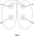
- FIG. 6 illustrates example placement of impedance sensors 102 relative to a patient's lungs. This placement may be used for treatment of CF, COPD, or similar pulmonary disorders. In this example, sensors are placed over the upper left, upper right, lower right, and lower left of the patient's thorax. These placements correspond with the positions of electromechanical actuators that are attached to a garment such as the vest 300 of FIG. 5 .
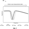
- FIG. 7 illustrates a graph of impedance on the y-axis plotted against frequency on the x-axis.
- the graph shows five different scans of frequencies using an existing REIS sweeping mechanism. This sweeps through the frequencies in order from lowest to highest. The result is noisy data and signal acquisition artifacts. There is significant variability in the order of the curve obtained, thereby preventing the acquisition of a reliable resonant point. It is theorized that noise is the result of a conventional resonant technique. Biological tissues does not behave as a linear system, so it is difficult to simplify the model to one of series or parallel impedance.
- Dielectric potentials and polarization potentials are alternatively exhausted and amplified by the presence of the AC electrical current itself. Ultimately, inducing a current at frequencies too close together does not allow the dielectric to recover from being exhausted. This causes variability and noise such that multiple reads need to be averaged to get a reliable result. However, this requires greater bandwidth in whichever system is employing the technique.
- a time order frequency hopping technique is used to spread induced noise across the entire region of interest. This allows the complex chemistries under sample time to recover from electrochemical polarization in any one frequency region prior to being exposed to a similar frequency.
- this algorithm can optionally be coupled with a vernier priority mechanism where the region of the curve you are interested in is rapidly localized and scanning intensified, while areas of little interest are interpolated. This modifies the procession of the scan appropriately.
- FIG. 8 is a graph illustrating an example of how the time order frequency hopping technique could be implemented.
- the frequency is plotted against impedance. "Sweeping" the frequency range of interest is done out of order instead of in sequential order. A first frequency is selected, measured, and then a second frequency a minimum distance away from the first is selected and measured, and so on. In this example, the first frequency selected for measurement is higher, the second is lower, the third is even higher than the first, the fourth is in the middle, and so on. Ultimately the entire range is sampled to provide measurements for all frequencies.
- an algorithm governs the operation of the modified frequency range sweep.
- FIG. 9 is a block diagram illustrating an example of the physical components of a computing device 400.
- the computing device 400 could be any computing device utilized in conjunction with the example system 100 of FIG. 1 for administering pulmonary therapy to a patient.
- the computing device 400 could operate as part of the computing system 106 used to control operation of the wearable therapy device 104.
- the computing device 400 includes at least one central processing unit (“CPU") 402, a system memory 408, and a system bus 422 that couples the system memory 408 to the CPU 402.
- the system memory 408 includes a random access memory (“RAM”) 410 and a read-only memory (“ROM”) 412.
- RAM random access memory
- ROM read-only memory
- the computing system 400 further includes a mass storage device 414.
- the mass storage device 414 can store software instructions and data such as therapy protocols and lookup tables.
- the mass storage device 414 is connected to the CPU 402 through a mass storage controller (not shown) connected to the system bus 422.
- the mass storage device 414 and its associated computer-readable storage media provide non-volatile, non-transitory data storage for the computing device 400.
- computer-readable storage media can include any available tangible, physical device or article of manufacture from which the CPU 402 can read data and/or instructions.
- the computer-readable storage media comprises entirely non-transitory media.
- Computer-readable storage media include volatile and non-volatile, removable and non-removable media implemented in any method or technology for storage of information such as computer-readable software instructions, data structures, program modules or other data.
- Example types of computer-readable data storage media include, but are not limited to, RAM, ROM, EPROM, EEPROM, flash memory or other solid state memory technology, CD-ROMs, digital versatile discs ("DVDs”), other optical storage media, magnetic cassettes, magnetic tape, magnetic disk storage or other magnetic storage devices, or any other medium which can be used to store the desired information and which can be accessed by the computing device 400.
- the computing device 400 can operate in a networked environment using logical connections to remote network devices through a network 108, such as a wireless network, the Internet, or another type of network.
- the computing device 400 may connect to the network 108 through a network interface unit 404 connected to the system bus 422. It should be appreciated that the network interface unit 404 may also be utilized to connect to other types of networks and remote computing systems.
- the computing device 400 also includes an input/output controller 406 for receiving and processing input from a number of other devices, including a touch user interface display screen, or another type of input device. Similarly, the input/output controller 406 may provide output to a touch user interface display screen or other type of output device.
- the mass storage device 414 and the RAM 410 of the computing device 400 can store software instructions and data.
- the software instructions include an operating system 418 suitable for controlling the operation of the computing device 400.
- the mass storage device 414 and/or the RAM 410 also store software instructions, that when executed by the CPU 402, cause the computing device 400 to provide the functionality discussed in this document.
- the mass storage device 414 and/or the RAM 410 can store software instructions that, when executed by the CPU 402, cause the computing system 400 to control operation of impedance sensors and pulmonary physiotherapy devices.
Landscapes
- Health & Medical Sciences (AREA)
- Life Sciences & Earth Sciences (AREA)
- Animal Behavior & Ethology (AREA)
- General Health & Medical Sciences (AREA)
- Public Health (AREA)
- Veterinary Medicine (AREA)
- Heart & Thoracic Surgery (AREA)
- Epidemiology (AREA)
- Pain & Pain Management (AREA)
- Physical Education & Sports Medicine (AREA)
- Rehabilitation Therapy (AREA)
- Physics & Mathematics (AREA)
- Medical Informatics (AREA)
- Biophysics (AREA)
- Pathology (AREA)
- Engineering & Computer Science (AREA)
- Biomedical Technology (AREA)
- Surgery (AREA)
- Molecular Biology (AREA)
- Pulmonology (AREA)
- Physiology (AREA)
- Nuclear Medicine, Radiotherapy & Molecular Imaging (AREA)
- Radiology & Medical Imaging (AREA)
- Cardiology (AREA)
- Emergency Medicine (AREA)
- Measurement And Recording Of Electrical Phenomena And Electrical Characteristics Of The Living Body (AREA)
Abstract
Description
- The measurement of the electrical impedance of biological tissues is known to hold significant promise for characterizing and diagnosing a vast myriad of clinical conditions and disease processes. It is known that different tissues have a characteristic impedance fingerprint. This fingerprint can be used in clinical interpretation.
- Embodiments of the disclosure are directed to monitoring medical therapies performed by wearable devices using electrical impedance sensors. The sensors operate to measure electrical impedance of bodily tissue. The medical therapy can be modified based on the impedance measurements to maximize efficacy.
- In one aspect, a medical therapy system comprises: a wearable medical therapy device comprising: one or more electromechanical components configured to administer a medical therapy to a patient; a plurality of impedimetric sensors configured to monitor the medical therapy, each of the impedimetric sensors comprising a source, a guard ring, and a probe; an electronic controller and a power source operatively connected to the one or more electromechanical components and plurality of impedimetric sensors, for generating and modulating an electrical signal to energize the one or more electromechanical components and plurality of impedimetric sensors; and a computing device in communication with the wearable medical therapy device, the computing device comprising: a processing device; and a memory device comprising: a data store comprising a lookup table of physiometric parameters; and instructions that, when executed by the processing device, cause the computing device to: a) determine a preliminary frequency range based on physiometric parameters of the patient and the lookup table; b) communicate instructions to the plurality of impedimetric sensors to sweep the preliminary frequency range; c) receive impedimetric measurements from the impedimetric sensors and plot them against their respective frequencies; d) identify a resonant point and feature and shape characteristics of a curve generated from the patient in the plot; d) communicate instructions to the wearable medical therapy device to initiate a therapy protocol based on the curve; e) monitor, with the plurality of impedimetric sensors, efficacy of the therapy protocol by measuring impedance over time; f) create a measurement matrix representing impedance measurements between pairs of the impedimetric sensors; g) analyze the measurements to determine efficacy of the therapy protocol for a physiological area of the body associated with a sensor location; h) based on the results of step g, modulate or modify the therapy protocol; and i) return to step e) and repeat until therapy has reached a measureable metric or concluded.
- In another aspect, a method of monitoring treatment efficacy of a body-worn medical therapy device comprises a) determining a preliminary probe frequency range based on physiometric parameters of the patient and the lookup table; b) communicating instructions to the plurality of impedimetric sensors to sweep the preliminary probe frequency range in a vernier technique; c) identifying a resonant point for the patient and determining an order of a curve for the impedance measurements; d) communicating instructions to the wearable thorax percussion device to initiate a therapy protocol, the therapy protocol comprising at least a duration and an intensity; e) monitoring, with the plurality of impedimetric sensors, respiration cycles of the patient and efficacy of the therapy protocol by measuring impedance over time, segmenting into analysis periods that coincide with the respiration cycles of the patient, and recording impedance measurements during peak volume of end inspiration; f) creating a measurement matrix representing impedance measurements between pairs of the impedimetric sensors, g) analyzing the measurements to determine efficacy of the therapy protocol for a physiological area of the thorax associated with a sensor location; h) based on the results of g, modulating or modifying the therapy protocol by adjusting one or more of duration and intensity; and i) returning to step e) and repeating until therapy has reached a measurable metric or concluded.
- In yet another aspect, a pulmonary physiotherapy system comprises: a wearable thorax percussion device for dislodging mucous buildup in the airways of a human patient, the device comprising: a garment fitting over a thorax of the patient; at least one frame element comprising a flat, rigid layer attached to an external surface of the garment; a plurality of electromechanical actuators retained by the at least one frame element, wherein the electromechanical actuators are positioned to provide intermittent percussion to the thorax; and an electronic controller and a power source operatively connected to the plurality of electromechanical actuators, for generating and modulating an electrical signal to energize the at least one actuator; a plurality of impedimetric sensors positioned proximate the plurality of electromechanical actuators, the impedimetric sensors comprising: a source electrode; a guard ring spaced from the source and surrounding the source in a circular form; and a probe electrode forming a semi-circular shape around a portion of the guard ring; and a computing device in communication with the wearable thorax percussion device and the plurality of impedimetric sensors, the computing device comprising: a processing device; and a memory device comprising: a data store comprising a lookup table of physiometric parameters; and instructions that, when executed by the processing device, cause the computing device to: a) determine a preliminary probe frequency range based on physiometric parameters of the patient and the lookup table; b) communicate instructions to the plurality of impedimetric sensors to sweep the preliminary probe frequency range in a vernier technique; c) identify a resonant point for the patient; d) communicate instructions to the wearable thorax percussion device to initiate a therapy protocol; e) monitor, with the plurality of impedimetric sensors, respiration cycles of the patient and efficacy of the therapy protocol by measuring impedance over time, segmenting into analysis periods that coincide with the respiration cycles of the patient, and recording impedance measurements during peak volume of end inspiration; f) create a measurement matrix representing impedance measurements between pairs of the impedimetric sensors, g) analyze the measurements to determine efficacy of the therapy protocol for a physiological area of the thorax associated with a sensor location; and h) based on the results of g, modulate or modify the therapy protocol by adjusting time, intensity, and/or frequency; and i) return to step e) and repeat until therapy has reached a measurable metric or has concluded.
- The details of one or more techniques are set forth in the accompanying drawings and the description below. Other features, objects, and advantages of these techniques will be apparent from the description, drawings, and claims.
- The invention will now be further described by way of example with reference to the accompanying drawings, in which:
-
FIG. 1 is a schematic diagram illustrating an example system for administering pulmonary therapy to a patient. -
FIG. 2 is a more detailed schematic diagram of the computing system ofFIG. 1 . -
FIG. 3 is a schematic diagram of an example impedance sensor. -
FIG. 4 is a flow chart of an example method of implementing a pulmonary physiotherapy protocol. -
FIG. 5 illustrates an example of a wearable device that is used to treat pulmonary diseases. -
FIG. 6 is a schematic diagram illustrating example impedance sensor placement relative to a patient's lungs. -
FIG. 7 illustrates a graph of impedance plotted against frequency for a conventional sequential method of sweeping a frequency range. -
FIG. 8 illustrates a graph of impedance plotted against frequency for a time order frequency hopping technique of sweeping a frequency range. -
FIG. 9 is a schematic block diagram of an example computing device usable to implement aspects of the system ofFIG. 1 . - The present disclosure is directed to systems and methods of monitoring medical therapies performed by wearable devices using electrical probes. In some embodiments, a pulmonary physiotherapy device implements a treatment protocol function gated and modulated using electrical impedance sensors and metrics.
- Electrical impedance measures the amount of opposition that a circuit provides to a current when voltage is applied to the circuit. One technique for measuring electrical impedance involves applying a sinusoidal voltage waveform to the circuit to be measured and measure the returned current and phase shift. Often measurements from multiple different frequencies are taken to produce a precise measurement of impedance in any linear system.
- In some instances, a frequency range of interest is continuously swept through as measurements are taken. For example, frequencies in the range of 100hz to 2Mhz might be swept for biological tissues, where ionic and dipolar forces predominate. Using this technique, an area known as the resonant point is located in a resultant plot of frequency against impedance. The resonant point indicates where the subject under test conditions transitions from operating as a capacitor to an inductor. The point and the region directly surrounding this point are of significant interest for physiological and biological measurements. The characteristics and order of the curve can demonstrate clinical condition and boundaries between fatty/dense tissue, profusion, air, bone, and the like. The curve can also distinguish between extracellular and intracellular fluids.
- Pulmonary disease in general is a chronic inflammatory lung disease that causes obstructed airflow from the lungs. Symptoms include breathing difficulty, cough, mucus (sputum) production and wheezing. There are three primary forms of lung disease: airway diseases, lung tissue diseases, and lung circulation diseases. Airway diseases affect the tubes (airways) that carry oxygen and other gases into and out of the lungs. They usually cause a narrowing or blockage of the airways. Airway diseases include asthma, chronic obstructive pulmonary disease (COPD) and bronchiectasis. Lung tissue diseases affect the structure of the lung tissue.
- Scarring or inflammation of the tissue makes the lungs unable to expand fully (restrictive lung disease). This makes it hard for the lungs to take in oxygen and release carbon dioxide. Pulmonary fibrosis and sarcoidosis are examples of lung tissue disease. Lung circulation diseases affect the blood vessels in the lungs. They are caused by clotting, scarring, or inflammation of the blood vessels. They affect the ability of the lungs to take up oxygen and release carbon dioxide. These diseases may also affect heart function. An example of a lung circulation disease is pulmonary hypertension.
- Cystic fibrosis (CF) is a hereditary chronic disease affecting human patients that causes the buildup of thick, sticky mucous in the lungs and other parts of the body. If left untreated, the mucous can clog air ways, and lead to complications such as tissue inflammation or infection, or other symptoms such as coughing, phlegm, and compromised cardio-respiratory performance. CF in particular is a good target for mechanical therapies to release and expel secretions from the lungs.
- Therapeutic medications for pulmonary disease are well known. Additional pulmonary therapy modalities include physiotherapy and mechanical manipulation of the subject. Lack of adherence to, or efficacy of, maintenance treatment including physiotherapy, is likely to be multifactorial, with factors including a large treatment burden or lack of understanding of the importance of this treatment. As pulmonary exacerbations may still occur even with optimum adherence, it is important for patients to continue maintenance therapies appropriately. Airway clearance is concomitant with airway surface liquid hydrators/mucolytics. These have specific electrical impedance characteristics.
- One technique to manage CF is chest physiotherapy (CPT), which involves the manipulation of the patient's thorax to dislodge mucous buildup in the airways and encourage expectoration of the mucous. CPT may have to be performed in several sessions in a day, with each session lasting from between 10 to 45 minutes. CPT can be performed manually by therapists who use their hands to repeatedly percuss the patient's thorax. However, manually performed CPT can be physically and time demanding and should only be performed by a properly trained therapist. Alternatively, CPT can be performed using handheld or wearable mechanical devices. Wearable devices have the advantage over handheld devices of relieving the therapist or patient from having to manipulate the device during the therapy session.
- One type of physiotherapy can be administered to patients at home using a wearable device that provides a mechanical means for CPT without the labor of a trained therapist. The device may be embodied in a form that is light weight, and ergonomically adapted to the anatomy of the thoracic region. An example of one such wearable device is described in
FIG. 5 . - The methods and systems described herein can be applied to other diseases and devices for treatment. Treatment for lymphedema, which is retention of water in tissues (common in cancer patients), can be treated with a peristaltic device. This massages the patient's legs to facilitate drainage of fluids. This is an example of a treatment that can be monitored with electrical impedance spectroscopy that is located in a part of the body other than the thorax.
- Another example is a cough assist machine. A mechanical insufflation-exsufflation device helps to clear secretions such as mucus from a patient's lungs by simulating a cough. The machine increased air pressure to inflate the lungs and then rapidly changes to negative air pressure to mobilize secretions out of the airway. The patient's thorax can be monitored by impedance spectroscopy to determine if treatment needs to be modified or concluded.
-
FIG. 1 is a schematic diagram illustrating anexample system 100 for administering pulmonary therapy to a patient P. While the figures show examples specific to pulmonary therapies, other types of devices could be used with the principles described, as mentioned above. - In the example shown in
FIG. 1 , thesystem 100 includes a plurality ofimpedimetric sensors 102 attached to a wearablemedical therapy device 104. Theimpedimetric sensors 102 are in communication with acomputing system 106 via acommunications network 108. Theimpedimetric sensors 102 operate to measure impedance of tissues of the patient P wearing themedical therapy device 104. In some embodiments, theimpedimetric sensors 102 are strategically placed on themedical therapy device 104 to position them over particular parts of the patient's body. - In this example, the wearable
medical therapy device 104 is a vest that includes a plurality of electromechanical actuators configured to provide intermittent percussion to the patient's thorax. Operation of the electromechanical actuators andimpedimetric sensors 102 is controlled by thecomputing system 106. In some embodiments, thecomputing system 106 is in direct, wired communication with thewearable garment 104. In some embodiments, thecomputing system 106 is a handheld electronic device attached to thegarment 104 for controlling operation of therapy. In some embodiments, thecomputing system 106 operates as part of a smartphone, laptop, or other wireless communications enabled device that can be utilized to operate thegarment 104 via Wi-Fi, Bluetooth, or other wireless communication methods. -
FIG. 2 is a more detailed schematic diagram of thecomputing system 106 ofFIG. 1 . Thecomputing system 106 operates to send instructions toimpedimetric sensors 102 and other components of a wearablemedical therapy device 104. Thecomputing system 106 also operates to receive data from various electronic components of the wearablemedical therapy device 104. Thecomputing system 106 includes a lookup table 152, afrequency controller 154, atherapy monitor 156, and atherapy controller 158. - In some embodiments, one or more of the components of the
computing system 106 are housed in a separate remote system in communication with thecomputing system 106. For example, the lookup table 152 could be located on a remote server instead of stored locally on thecomputing system 106. In some embodiments, all of the components of thecomputing system 106 are incorporated into one computing device such as a laptop, a smartphone, or a tablet. In some embodiments, thecomputing system 106 is housed in a remote control in wired or wireless communication with the wearablemedical therapy device 104. - The lookup table 152 stores preliminary probe frequency ranges that correspond to patient physiometric parameters. In some embodiments, the patient's weight, height, age, and clinical standing are used to look up an appropriate preliminary probe frequency range for therapy. This provides an optimal signal response in the region between surface conduction of the mucosal membranes and cellular conduction. In some embodiments, the lookup table 152 is stored at a remote server and is accessed with a wireless connection to the
computing system 106. One non-limiting example of a portion of one such lookup table for female patients is provided in Table 1 below.Table 1: Female Patient Lookup Table Weight Height Age Clinical standing Current Probe freq range Average Short Pediatric Fair health 100uA 0-1Mhz Overweight Short Pediatric Fair health 250uA 0-1Mhz Average Average Pediatric Fair health 500uA 0-750 kHz Overweight Average Pediatric Fair health 1mA 0-750 kHz Average Tall Pediatric Fair health 1.250mA 0-500 kHz Overweight Tall Pediatric Fair health 1.5mA 0-500 kHz Average Short Early Adult Fair health 1mA 0-1Mhz Overweight Short Early Adult Fair health 1.250mA 0-1Mhz Average Average Early Adult Fair health 1.5mA 0-750 kHz Overweight Average Early Adult Fair health 1.750mA 0-750 kHz Average Tall Early Adult Fair health 2mA 0-500 kHz Overweight Tall Early Adult Fair health 2.250mA 0-500 kHz Average Short Older Adult Fair health 1.5mA 0-1Mhz Overweight Short Older Adult Comorbidities 1.75mA 0-1Mhz Average Average Older Adult Comorbidities 2mA 0-750 kHz Overweight Average Older Adult Chronic Disease 2.250mA 0-750 kHz Average Tall Older Adult Chronic Disease 2.250mA 0-500 kHz Overweight Tall Older Adult Chronic Disease 2.250mA 0-500 kHz - The
frequency controller 154 operates to control the operation of theimpedimetric sensors 102. Thefrequency controller 154 communicates instructions to theimpedimetric sensors 102 to sweep the preliminary frequency range to find the resonant point. Thefrequency controller 154 also communicates instructions to theimpedimetric sensors 102 to measure impedance between pairs ofimpedimetric sensors 102. Further detail on the functioning of thefrequency controller 154 are provided inFIG. 4 . - The
therapy monitor 156 operates to monitor impedance measurements recorded by theimpedimetric sensors 102 throughout a therapy session. Impedance is measured to determine respiration cycle and to determine treatment efficacy. Algorithms are employed to determine how well secretions are being cleared from the patient's lungs. As measurements are taken, thetherapy monitor 156 determines whether intensity of therapy or duration of therapy should be modified. For example, if the algorithm calculates that the amount of extracellular fluid is not going down quickly enough, the intensity of the therapy may need to be increased. Alternatively, if the amount of extracellular fluid is going down very quickly, the therapy duration could be shortened. - The
therapy controller 158 communicates instructions to the garment device to initiate and modify therapy protocols. Therapy protocols are selected based on a resonant point and order of a curve determined by sweeping an initial frequency range (performed by the frequency controller 154). Modifications are made to therapy protocols based on information received from thetherapy monitor 156 indicating that a therapy session is more or less effective than expected. -
FIG. 3 is a schematic diagram of anexample impedance sensor 102. Theimpedance sensor 102 includes asource 202, aguard ring 204, and aprobe 206. Signal from thesource 202 travels throughout all possible paths in the body and is recorded at theprobe 206. Theprobe 206 is advantageously positioned within the same sensor, eliminating the need for separate sources and probes. To eliminate an overabundance of current coming from thesource 202 directly to theprobe 206, a guard ring surrounds thesource 202. This allows for asource 202 of a first sensor to send current to aprobe 206 of a second sensor. For example, using the probe layout shown inFIG. 6 , one measurement could be from the source of the upper left sensor to the probe of the upper right sensor. Another measurement is from the source of the upper right sensor to the probe of the lower left sensor. All possible pairs are measured and recorded. - This sensor design is advantageous in that each sensor includes both a source and a probe, so that fewer electrodes are required. Additionally, the guard ring reduces the amount of signal that is recorded between the source and probe of the same sensor.
-
FIG. 4 is a flow chart of anexample method 250 of implementing a pulmonary physiotherapy therapy protocol. In some embodiments, thismethod 250 is performed using thesystem 100 ofFIG. 1 . - At
operation 252, a preliminary probe frequency range is determined. Physiometric parameters of a patient that is receiving therapy are used to look up the preliminary probe frequency range in a lookup table. In some embodiments, the physiometric parameters include weight, height, age, and clinical standing of the patient. The preliminary probe frequency is selected to provide an optimal signal response in the region between surface conduction of the mucosal membranes and cellular conduction. - At
operation 254, the preliminary frequency range is swept. In some embodiments, this is performed in a vernier technique. In some embodiments, a time order-based frequency hopping technique is used. An example sweeping technique is described in greater detail with respect toFIG. 8 . This step occurs after thewearable garment 104 is positioned on the patient so that theimpedance sensors 102 are in contact with the patient's body. Thus, the subject for a wearable physiotherapy device is a patient's thorax. - At
operation 256, the resonant point is localized. The resonant point represents the maximal impedance point. The resonant point is used to identify a curve in a graph plotting impedance against frequency. The order of the curve of that graph is used to determine a therapy protocol. - At
operation 258, a therapy protocol is initiated. In some embodiments, a command is sent from a computing system to the therapy device. The computing system may be in wireless communication with the device or may be an attached remote control. The therapy protocol is selected based on the physiometric parameters of the patient as well as the results of the initial frequency sweep. The percussive actuators are prompted to begin actuating to percuss the patient's thorax according to the therapy protocol. - At
operation 260, impedance measurements are taken with the impedance sensors. The sensors can use dry or wet electrodes that are in contact with the patient's body. These measurements are used to monitor the respiration cycle of the patient as well as the efficacy of the therapy. The respiration cycle is measured in order to determine when to record the impedance to monitor therapy. Measurements are segmented into analysis periods defined by the respiratory cycle. Measurements are taken at the same point in the respiratory cycle to ensure consistency. In some embodiments, measurements are made during peak volume of end inspiration. - At
operation 262, a measurement matrix is created that represents impedance measurements between each pair of impedimetric sensors. In some embodiments, there are four impedimetric sensors placed on four quadrants of the patient's lungs. The matrix can be constructed such that there is a measurement for each pair, where the pairs include: upper left to lower left, upper left to upper right, upper left to lower right, lower left to upper right, lower left to lower right, and upper right to lower right. A schematic illustrating the positions of the impedimetric sensors is illustrated inFIG. 6 . - At
operation 264, the measurements in the matrix are analyzed to determine efficacy of the therapy protocol. An algorithm is used to determine if intensity or duration of the therapy needs to be modified. For example, if the therapy is proving to be very effective, the duration of the therapy could be shortened. If the therapy is not progressing as quickly as expected, the duration could be extended or the intensity could be increased. In some embodiments, the algorithm can determine if therapy is recommended for the patient more or less frequently. - At
operation 264, the therapy protocol is modified if needed. Then, the method returns tooperation 260 and continues to cycle until the therapy protocol ends. Once the therapy has ceased, the patient can remove thewearable device 104. -
FIG. 5 illustrates an example of awearable device 104 that is used to treat pulmonary diseases such as cystic fibrosis (CF). In this example, thewearable device 104 takes the form of avest 300 having afront frame element 320 and arear frame element 330 interconnected with thevest 300 material. Theframe elements electromechanical actuators 360 that are configured to provide percussion to a patient's thorax at particular locations. A plurality ofimpedimetric sensors 102 are attached to thevest 300 at the same locations as theelectromechanical actuators 360. In this example, there are fourelectromechanical actuators 360 on thefront frame element 320 and fourelectromechanical actuators 360 on therear frame element 330. Thus, there are also fourimpedimetric sensors 102 on thefront frame element 320 and fourimpedimetric sensors 102 on therear frame element 330. The colocation of theimpedimetric sensors 102 with theelectromechanical actuators 360 ensures that impedimetric measurements are specific to each therapy location. - The
vest 300 may comprise a variety of fasteners and adjustments to facilitate fitting the garment to a patient's thorax and positioning theframe elements vest 300 may open and close with hook and loop fasteners, or other conventional fasteners such as zippers, clips or buttons, to permit the patient to don thevest 300. Additionally, or alternatively, the garment may be made of an elastic material to permit the user to slip thevest 300 on, or to adjust to individual body shapes, or both. - The
vest 300 is preferably constructed of a light-weight, flexible and elastic material to accommodate the contours of the thorax. Thevest 300 may separate theactuators 360 from the user to protect the user from pinch points of moving components or electronic components associated with theactuators 360. Alternatively, the garment may define openings through which the actuators may contact the user. In some embodiments, theimpedimetric sensors 102 contact the skin of the patient. In some embodiments, the sensors utilize wet electrodes for better conductivity. In some embodiments, dry electrodes are used for greater patient comfort. -
FIG. 6 illustrates example placement ofimpedance sensors 102 relative to a patient's lungs. This placement may be used for treatment of CF, COPD, or similar pulmonary disorders. In this example, sensors are placed over the upper left, upper right, lower right, and lower left of the patient's thorax. These placements correspond with the positions of electromechanical actuators that are attached to a garment such as thevest 300 ofFIG. 5 . -
FIG. 7 illustrates a graph of impedance on the y-axis plotted against frequency on the x-axis. The graph shows five different scans of frequencies using an existing REIS sweeping mechanism. This sweeps through the frequencies in order from lowest to highest. The result is noisy data and signal acquisition artifacts. There is significant variability in the order of the curve obtained, thereby preventing the acquisition of a reliable resonant point. It is theorized that noise is the result of a conventional resonant technique. Biological tissues does not behave as a linear system, so it is difficult to simplify the model to one of series or parallel impedance. - Dielectric potentials and polarization potentials are alternatively exhausted and amplified by the presence of the AC electrical current itself. Ultimately, inducing a current at frequencies too close together does not allow the dielectric to recover from being exhausted. This causes variability and noise such that multiple reads need to be averaged to get a reliable result. However, this requires greater bandwidth in whichever system is employing the technique.
- To address this problem, a time order frequency hopping technique is used to spread induced noise across the entire region of interest. This allows the complex chemistries under sample time to recover from electrochemical polarization in any one frequency region prior to being exposed to a similar frequency. To mitigate the loss of bandwidth forced in waiting for results - this algorithm can optionally be coupled with a vernier priority mechanism where the region of the curve you are interested in is rapidly localized and scanning intensified, while areas of little interest are interpolated. This modifies the procession of the scan appropriately.
-
FIG. 8 is a graph illustrating an example of how the time order frequency hopping technique could be implemented. As inFIG. 7 , the frequency is plotted against impedance. "Sweeping" the frequency range of interest is done out of order instead of in sequential order. A first frequency is selected, measured, and then a second frequency a minimum distance away from the first is selected and measured, and so on. In this example, the first frequency selected for measurement is higher, the second is lower, the third is even higher than the first, the fourth is in the middle, and so on. Ultimately the entire range is sampled to provide measurements for all frequencies. - In some embodiments, an algorithm governs the operation of the modified frequency range sweep. The following are parameters of one such algorithm:
- Region of exclusion (ROE: fixed or dynamic area not to be probed successively within "time window"; hz)
- Time window (TW: the amount of time to wait before a frequency region can be probed again; units of samples)
- Vernier Region Size (VRS: the size of the region of interest used for successive probes units of hz)
- Random seed (RS: the frequency to start the probe, randomly obtained and gated by the other parameters; hz)
- In an example base case there could be a ROE of 0, a TW of 0, and VRS of 100%. This would result in a simple random frequency hopping mechanism. The system would randomly probe the entire spectrum requested, then sort the results and reproduce a conventional curve. This yields some benefit. However, increasing the ROE and TW would prevent random duplicate localized hits, and thereby increase the specificity of results.
- If implemented properly, these mechanisms both increase the specificity of the test and the effective bandwidth (total test time). All samples obtained are ordered (sorted) after they are measured. This puts them onto the conventional frequency spectrum, or nyquist diagram.
-
FIG. 9 is a block diagram illustrating an example of the physical components of acomputing device 400. Thecomputing device 400 could be any computing device utilized in conjunction with theexample system 100 ofFIG. 1 for administering pulmonary therapy to a patient. Thecomputing device 400 could operate as part of thecomputing system 106 used to control operation of thewearable therapy device 104. - In the example shown in
FIG. 9 , thecomputing device 400 includes at least one central processing unit ("CPU") 402, asystem memory 408, and asystem bus 422 that couples thesystem memory 408 to theCPU 402. Thesystem memory 408 includes a random access memory ("RAM") 410 and a read-only memory ("ROM") 412. A basic input/output system that contains the basic routines that help to transfer information between elements within thecomputing device 400, such as during startup, is stored in theROM 412. Thecomputing system 400 further includes amass storage device 414. Themass storage device 414 can store software instructions and data such as therapy protocols and lookup tables. - The
mass storage device 414 is connected to theCPU 402 through a mass storage controller (not shown) connected to thesystem bus 422. Themass storage device 414 and its associated computer-readable storage media provide non-volatile, non-transitory data storage for thecomputing device 400. Although the description of computer-readable storage media contained herein refers to a mass storage device, such as a hard disk or solid state disk, it should be appreciated by those skilled in the art that computer-readable data storage media can include any available tangible, physical device or article of manufacture from which theCPU 402 can read data and/or instructions. In certain embodiments, the computer-readable storage media comprises entirely non-transitory media. - Computer-readable storage media include volatile and non-volatile, removable and non-removable media implemented in any method or technology for storage of information such as computer-readable software instructions, data structures, program modules or other data. Example types of computer-readable data storage media include, but are not limited to, RAM, ROM, EPROM, EEPROM, flash memory or other solid state memory technology, CD-ROMs, digital versatile discs ("DVDs"), other optical storage media, magnetic cassettes, magnetic tape, magnetic disk storage or other magnetic storage devices, or any other medium which can be used to store the desired information and which can be accessed by the
computing device 400. - According to various embodiments, the
computing device 400 can operate in a networked environment using logical connections to remote network devices through anetwork 108, such as a wireless network, the Internet, or another type of network. Thecomputing device 400 may connect to thenetwork 108 through anetwork interface unit 404 connected to thesystem bus 422. It should be appreciated that thenetwork interface unit 404 may also be utilized to connect to other types of networks and remote computing systems. Thecomputing device 400 also includes an input/output controller 406 for receiving and processing input from a number of other devices, including a touch user interface display screen, or another type of input device. Similarly, the input/output controller 406 may provide output to a touch user interface display screen or other type of output device. - As mentioned briefly above, the
mass storage device 414 and theRAM 410 of thecomputing device 400 can store software instructions and data. The software instructions include anoperating system 418 suitable for controlling the operation of thecomputing device 400. Themass storage device 414 and/or theRAM 410 also store software instructions, that when executed by theCPU 402, cause thecomputing device 400 to provide the functionality discussed in this document. For example, themass storage device 414 and/or theRAM 410 can store software instructions that, when executed by theCPU 402, cause thecomputing system 400 to control operation of impedance sensors and pulmonary physiotherapy devices. - Although various embodiments are described herein, those of ordinary skill in the art will understand that many modifications may be made thereto within the scope of the present disclosure. Accordingly, it is not intended that the scope of the disclosure in any way be limited by the examples provided.
- Embodiments of the invention can be described with reference to the following numbered clauses, with preferred features laid out in the dependent clauses:
- 1. A pulmonary physiotherapy system comprising:
- a wearable thorax percussion device for dislodging mucous buildup in the airways of a human patient, the device comprising:
- a garment fitting over a thorax of the patient;
- at least one frame element comprising a flat, rigid layer attached to an external surface of the garment;
- a plurality of electromechanical actuators retained by the at least one frame element, wherein the electromechanical actuators are positioned to provide intermittent percussion to the thorax; and
- an electronic controller and a power source operatively connected to the plurality of electromechanical actuators, for generating and modulating an electrical signal to energize the at least one actuator;
- a plurality of impedimetric sensors positioned proximate the plurality of electromechanical actuators, the impedimetric sensors comprising:
- a source electrode;
- a guard ring spaced from the source and surrounding the source in a circular form; and
- a probe electrode forming a semi-circular shape around a portion of the guard ring; and
- a computing device in communication with the wearable thorax percussion device and the plurality of impedimetric sensors, the computing device comprising:
- a processing device; and
- a memory device comprising:
- a data store comprising a lookup table of physiometric parameters; and
- instructions that, when executed by the processing device, cause the computing device to:
- a) determine a preliminary probe frequency range based on physiometric parameters of the patient and the lookup table;
- b) communicate instructions to the plurality of impedimetric sensors to sweep the preliminary probe frequency range in a vernier technique;
- c) identify a resonant point for the patient;
- d) communicate instructions to the wearable thorax percussion device to initiate a therapy protocol;
- e) monitor, with the plurality of impedimetric sensors, respiration cycles of the patient and efficacy of the therapy protocol by measuring impedance over time, segmenting into analysis periods that coincide with the respiration cycles of the patient, and recording impedance measurements during peak volume of end inspiration;
- f) create a measurement matrix representing impedance measurements between pairs of the impedimetric sensors,
- g) analyze the measurements to determine efficacy of the therapy protocol for a physiological area of the thorax associated with a sensor location; and
- h) based on the results of g, modulate or modify the therapy protocol by adjusting time, intensity, and/or frequency; and
- i) return to step e) and repeat until therapy has reached a measurable metric or has concluded.
- a wearable thorax percussion device for dislodging mucous buildup in the airways of a human patient, the device comprising:
Claims (15)
- A medical therapy system, comprising:a wearable medical therapy device comprising:one or more electromechanical components configured to administer a medical therapy to a patient;a plurality of impedimetric sensors configured to monitor the medical therapy, each of the impedimetric sensors comprising a source, a guard ring, and a probe;an electronic controller and a power source operatively connected to the one or more electromechanical components and plurality of impedimetric sensors, for generating and modulating an electrical signal to energize the one or more electromechanical components and plurality of impedimetric sensors; anda computing device in communication with the wearable medical therapy device, the computing device comprising:a processing device; anda memory device comprising:a data store comprising a lookup table of physiometric parameters; andinstructions that, when executed by the processing device, cause the computing device to:a) determine a preliminary frequency range based on physiometric parameters of the patient and the lookup table;b) communicate instructions to the plurality of impedimetric sensors to sweep the preliminary frequency range;c) receive impedimetric measurements from the impedimetric sensors and plot them against their respective frequencies;d) identify a resonant point and feature and shape characteristics of a curve generated from the patient in the plot;d) communicate instructions to the wearable medical therapy device to initiate a therapy protocol based on the curve;e) monitor, with the plurality of impedimetric sensors, efficacy of the therapy protocol by measuring impedance over time;f) create a measurement matrix representing impedance measurements between pairs of the impedimetric sensors;g) analyze the measurements to determine efficacy of the therapy protocol for a physiological area of the body associated with a sensor location;h) based on the results of step g, modulate or modify the therapy protocol; andi) return to step e) and repeat until therapy has reached a measureable metric or concluded.
- The medical therapy system of claim 1, wherein the wearable medical therapy device is a pulmonary physiotherapy garment and the electromechanical components are electromechanical actuators configured to provide high frequency percussion to the patient's thorax.
- The medical therapy system of claim 2, wherein the pulmonary physiotherapy garment comprises a vest and at least one frame element comprising a flat, rigid layer attached to the vest.
- The medical therapy system of any preceding claim, wherein the impedimetric sensors comprise a substantially flat substrate having the source, guard ring, and probe arranged in a single plane, wherein the source is positioned at a central portion of the substrate, the guard ring is spaced from the source, forming a circumferential barrier around the source, and the probe is spaced from the guard ring and forming a semi-circular shape around a portion of the guard ring.
- The medical therapy system of any preceding claim, wherein the physiometric parameters comprise weight, height, age, and clinical standing of the patient.
- The medical therapy system of any preceding claim, wherein the preliminary frequency range is swept in a time order based frequency hopping technique by selecting and measuring a plurality of frequencies within the preliminary frequency range one at a time, wherein each subsequent frequency is a minimum distance from the previous frequency.
- The medical therapy system of claim 6, wherein the frequencies are selected using a vernier technique to increase selection of frequencies close to a region of interest.
- The medical therapy system of any preceding claim, wherein the therapy protocol is modified by increasing or decreasing one or both of intensity and duration.
- The medical therapy system of any preceding claim, wherein the wearable medical therapy device is a cough assist device configured to manipulate air pressure in the patient's lungs to expel secretions.
- The medical therapy system of any preceding claim, wherein the wearable medical therapy device is a peristaltic device configured to facilitate drainage of fluids from the patient's legs.
- A method of monitoring treatment efficacy of a body-worn medical therapy device, the method comprising:a) determining a preliminary probe frequency range based on physiometric parameters of the patient and the lookup table;b) communicating instructions to the plurality of impedimetric sensors to sweep the preliminary probe frequency range in a vernier technique;c) identifying a resonant point for the patient and determining an order of a curve for the impedance measurements;d) communicating instructions to the wearable thorax percussion device to initiate a therapy protocol, the therapy protocol comprising at least a duration and an intensity;e) monitoring, with the plurality of impedimetric sensors, respiration cycles of the patient and efficacy of the therapy protocol by measuring impedance over time, segmenting into analysis periods that coincide with the respiration cycles of the patient, and recording impedance measurements during peak volume of end inspiration;f) creating a measurement matrix representing impedance measurements between pairs of the impedimetric sensors,g) analyzing the measurements to determine efficacy of the therapy protocol for a physiological area of the thorax associated with a sensor location;h) based on the results of g, modulating or modifying the therapy protocol by adjusting one or more of duration and intensity; andi) returning to step e) and repeating until therapy has reached a measurable metric or concluded.
- The method of claim 11, wherein the body-worn medical therapy device comprises a pulmonary physiotherapy vest for providing high frequency chest wall oscillation therapy to a patient.
- The method of claim 12, wherein the vest comprises at least one frame element comprising a flat, rigid layer attached to the vest and a plurality of electromechanical actuators retained by the at least one frame element and configured to provide intermittent oscillations to one or more locations of the patient's chest wall to loosen lung secretions.
- The method of claim any one of claims 11-13, wherein the impedimetric sensors comprise a substantially flat substrate having the source, guard ring, and probe arranged in a single plane, wherein the source is positioned at a central portion of the substrate, the guard ring is spaced from the source, forming a circumferential barrier around the source, and the probe is spaced from the guard ring and forming a semi-circular shape around a portion of the guard ring.
- The method of any one of claims 11-14, wherein the preliminary frequency range is swept in a time order-based frequency hopping technique by selecting and measuring a plurality of frequencies within the preliminary frequency range one at a time, wherein each subsequent frequency is a minimum distance from the previous frequency.
Applications Claiming Priority (2)
| Application Number | Priority Date | Filing Date | Title |
|---|---|---|---|
| US202062706151P | 2020-08-03 | 2020-08-03 | |
| US17/443,065 US12303455B2 (en) | 2020-08-03 | 2021-07-20 | Therapeutic technique using electrical impedance spectroscopy |
Publications (1)
| Publication Number | Publication Date |
|---|---|
| EP3949834A1 true EP3949834A1 (en) | 2022-02-09 |
Family
ID=77168061
Family Applications (1)
| Application Number | Title | Priority Date | Filing Date |
|---|---|---|---|
| EP21189024.9A Pending EP3949834A1 (en) | 2020-08-03 | 2021-08-02 | Therapeutic technique using electrical impedance spectroscopy |
Country Status (3)
| Country | Link |
|---|---|
| US (1) | US12303455B2 (en) |
| EP (1) | EP3949834A1 (en) |
| CN (1) | CN114081467B (en) |
Families Citing this family (1)
| Publication number | Priority date | Publication date | Assignee | Title |
|---|---|---|---|---|
| CN120093273B (en) * | 2025-05-07 | 2025-09-02 | 南方科技大学 | Sputum obstruction detection method, system, terminal and medium based on lung binary tree model |
Citations (3)
| Publication number | Priority date | Publication date | Assignee | Title |
|---|---|---|---|---|
| US20140005579A1 (en) * | 2012-06-29 | 2014-01-02 | Chestmaster Inc. | Wearable thorax percussion device |
| WO2018226999A1 (en) * | 2017-06-07 | 2018-12-13 | Respiratory Motion, Inc. | Respiratory volume monitor and ventilator |
| US20190274919A1 (en) * | 2018-03-06 | 2019-09-12 | Koninklijke Philips N.V. | High frequency chest wall oscillator |
Family Cites Families (78)
| Publication number | Priority date | Publication date | Assignee | Title |
|---|---|---|---|---|
| US3447071A (en) * | 1965-09-22 | 1969-05-27 | Webb James E | Probes having guard ring and primary sensor at same potential to prevent collection of stray wall currents in ionized gases |
| WO2000027334A2 (en) * | 1998-11-09 | 2000-05-18 | Johns Hopkins University | Automated chest compression apparatus |
| AU1989100A (en) | 1999-01-05 | 2000-07-24 | Kaiku Limited | Impedance measurements of bodily matter |
| US8257288B2 (en) | 2000-06-29 | 2012-09-04 | Respirtech | Chest compression apparatus having physiological sensor accessory |
| US6602201B1 (en) * | 2000-07-10 | 2003-08-05 | Cardiodynamics International Corporation | Apparatus and method for determining cardiac output in a living subject |
| US6676614B1 (en) * | 2000-07-11 | 2004-01-13 | Electromed, Inc. | Vest for body pulsating method and apparatus |
| US7229423B2 (en) * | 2003-02-05 | 2007-06-12 | Timi 3 System, Inc | Systems and methods for applying audible acoustic energy to increase tissue perfusion and/or vasodilation |
| GB0228375D0 (en) | 2002-12-05 | 2003-01-08 | Innovation And Entpr Off Of | Wound mapping |
| GB2396426B (en) | 2002-12-21 | 2005-08-24 | Draeger Medical Ag | Artificial respiration system |
| US20080082018A1 (en) * | 2003-04-10 | 2008-04-03 | Sackner Marvin A | Systems and methods for respiratory event detection |
| EP2008581B1 (en) | 2003-08-18 | 2011-08-17 | Cardiac Pacemakers, Inc. | Patient monitoring, diagnosis, and/or therapy systems and methods |
| US9820658B2 (en) * | 2006-06-30 | 2017-11-21 | Bao Q. Tran | Systems and methods for providing interoperability among healthcare devices |
| US7907997B2 (en) * | 2005-05-11 | 2011-03-15 | Cardiac Pacemakers, Inc. | Enhancements to the detection of pulmonary edema when using transthoracic impedance |
| US8052626B2 (en) * | 2006-05-10 | 2011-11-08 | Hill-Rom Services Pte. Ltd. | Data handling for high frequency chest wall oscillation system |
| US20080108914A1 (en) * | 2006-11-03 | 2008-05-08 | Laurent Brouqueyre | Low Frequency Lung Vibration and Sputum Removal Apparatus |
| CA2684324C (en) * | 2007-04-20 | 2017-05-30 | Impedimed Limited | Monitoring system and probe |
| US7769464B2 (en) | 2007-04-30 | 2010-08-03 | Medtronic, Inc. | Therapy adjustment |
| US8527028B2 (en) * | 2007-05-16 | 2013-09-03 | Medicomp, Inc. | Harness with sensors |
| US20090309578A1 (en) * | 2008-06-16 | 2009-12-17 | Cochran William T | Sensor inductors, sensors for monitoring movements and positioning, apparatus, systems and methods therefore |
| US8217667B2 (en) * | 2009-01-16 | 2012-07-10 | Hill-Rom Services, Inc. | Method and apparatus for piezoelectric sensor status assessment |
| US9002427B2 (en) * | 2009-03-30 | 2015-04-07 | Lifewave Biomedical, Inc. | Apparatus and method for continuous noninvasive measurement of respiratory function and events |
| US8752220B2 (en) * | 2009-07-10 | 2014-06-17 | Hill-Rom Services, Inc. | Systems for patient support, monitoring and treatment |
| US8715206B2 (en) * | 2009-10-15 | 2014-05-06 | Masimo Corporation | Acoustic patient sensor |
| US9173594B2 (en) * | 2010-04-19 | 2015-11-03 | Sotera Wireless, Inc. | Body-worn monitor for measuring respiratory rate |
| US10702166B1 (en) * | 2010-08-13 | 2020-07-07 | Respiratory Motion, Inc. | Devices and methods for respiratory variation monitoring by measurement of respiratory volumes, motion and variability |
| US9017256B2 (en) * | 2010-09-22 | 2015-04-28 | Milieu Institute, Llc | System and method for physiological monitoring |
| WO2012125425A2 (en) * | 2011-03-11 | 2012-09-20 | Proteus Biomedical, Inc. | Wearable personal body associated device with various physical configurations |
| WO2013103361A2 (en) * | 2011-04-08 | 2013-07-11 | Zoll Medical Corporation | Coordinated resuscitation perfusion support |
| WO2013013153A1 (en) * | 2011-07-20 | 2013-01-24 | Respiratory Motion, Inc. | Impedance measuring devices and methods for emergency cardiovascular care |
| JP2014523795A (en) | 2011-07-28 | 2014-09-18 | ブリガム・アンド・ウイミンズ・ホスピタル・インコーポレイテッド | System and method for portable magnetic resonance measurement of lung characteristics |
| WO2013128306A1 (en) * | 2012-02-28 | 2013-09-06 | Koninklijke Philips N.V. | Combined aed and cpr delivery assistance unit |
| US10016335B2 (en) | 2012-03-27 | 2018-07-10 | Electromed, Inc. | Body pulsating apparatus and method |
| US20130289456A1 (en) * | 2012-03-30 | 2013-10-31 | Mike Yang Chang Guo | Garment based airway clearance systems and methods |
| FI124977B (en) * | 2012-04-03 | 2015-04-15 | Tide Medical Oy | Measurement of lung volume changes with impedance pneumography |
| US20130331676A1 (en) * | 2012-06-08 | 2013-12-12 | Medtronic Minimed, Inc. | Application of electrochemical impedance spectroscopy in sensor systems, devices, and related methods |
| US9549869B2 (en) * | 2012-06-29 | 2017-01-24 | Hill-Rom Canado Respiratory Ltd. | Wearable thorax percussion device |
| EP2892429B1 (en) * | 2012-09-10 | 2019-07-24 | Koninklijke Philips N.V. | Device and method to improve dependability of physiological parameter measurements |
| RU2012158254A (en) | 2012-12-29 | 2014-07-10 | Федеральное государственное бюджетное учреждение "Российский научный центр медицинской реабилитации и курортологии" Министерства здравоохранения Российской Федерации (ФГБУ "РНЦ МРиК" Минздрава России) | HARDWARE AND SOFTWARE COMPLEX FOR EVALUATING THE FUNCTIONAL RESERVES OF THE ORGANISM AND THE RISK OF THE DEVELOPMENT OF DISEASES |
| DE102013213534A1 (en) | 2013-02-05 | 2014-08-07 | Dräger Medical GmbH | Electroimpedance tomography apparatus and method |
| WO2015137999A1 (en) | 2014-03-12 | 2015-09-17 | Hill-Rom Services, Inc. | Method and apparatus for the detection of moisture and multifunctional sensor system |
| SG11201509901VA (en) * | 2013-06-06 | 2016-01-28 | Tricord Holdings L L C | Modular physiologic monitoring systems, kits, and methods |
| EP3013420B1 (en) * | 2013-06-24 | 2021-09-15 | ZetrOZ Systems, LLC | Wearable ultrasound device |
| US10828007B1 (en) * | 2013-10-11 | 2020-11-10 | Masimo Corporation | Acoustic sensor with attachment portion |
| CN106061456A (en) * | 2013-12-31 | 2016-10-26 | 伊夫徳发明未来科技有限公司 | Wearable devices, systems, methods and architectures for sensory stimulation and manipulation, and physiological data acquisition |
| US11147507B2 (en) * | 2014-02-03 | 2021-10-19 | Oridion Medical 1987 Ltd. | Decision support system for cardiopulmonary resuscitation (CPR) |
| US20150265221A1 (en) | 2014-03-19 | 2015-09-24 | Boston Scientific Scimed, Inc. | Methods and systems for diagnostic monitoring |
| WO2015191761A1 (en) * | 2014-06-10 | 2015-12-17 | Zoll Medical Corporation | Determining initial treatments from spectral data |
| US9913611B2 (en) * | 2014-11-10 | 2018-03-13 | MAD Apparel, Inc. | Garment integrated sensing system and method |
| US9788893B2 (en) | 2014-11-20 | 2017-10-17 | Biosense Webster (Israel) Ltd. | Catheter with soft distal tip for mapping and ablating tubular region |
| US11324443B2 (en) * | 2015-03-26 | 2022-05-10 | Zoll Medical Corporation | Amplitude spectrum area considerations for an external medical monitoring and treatment device |
| US10772793B2 (en) * | 2015-06-12 | 2020-09-15 | Norman A. Paradis | Mechanical cardiopulmonary resuscitation combining circumferential constriction and anteroposterior compression of the chest |
| AU2015100881A4 (en) | 2015-07-02 | 2015-08-06 | Makkar, Shrey MR | Focused Impedance Method for Monitoring Respiratory Rate |
| US10518048B2 (en) * | 2015-07-31 | 2019-12-31 | Hill-Rom Services, PTE Ltd. | Coordinated control of HFCWO and cough assist devices |
| JP6940483B2 (en) * | 2015-08-31 | 2021-09-29 | マシモ・コーポレイション | Wireless patient monitoring system and method |
| US11166666B2 (en) | 2015-10-09 | 2021-11-09 | Koninklijke Philips N.V. | Enhanced acute care management combining imaging and physiological monitoring |
| US10660531B1 (en) * | 2015-10-16 | 2020-05-26 | Furaxa, Inc. | Method and apparatus for non-invasive real-time biomedical imaging of neural and vascular activity |
| US11141100B2 (en) * | 2015-12-23 | 2021-10-12 | Coloplast A/S | Moisture assessment system and method for wound care |
| US20190015233A1 (en) * | 2016-01-05 | 2019-01-17 | President And Fellows Of Harvard College | Fabric-Based Soft Actuators |
| AU2017220381B2 (en) * | 2016-02-16 | 2022-01-20 | Impedimed Limited | Body state classification |
| US11833096B2 (en) * | 2016-03-21 | 2023-12-05 | The Trustees Of The University Of Pennsylvania | Ambulatory respiratory assist device |
| US20170290732A1 (en) | 2016-04-08 | 2017-10-12 | Hld Healthy Life Devices Oy | Low pressure suction treatment incorporating measurement of tissue characteristics |
| US10780020B2 (en) * | 2016-09-30 | 2020-09-22 | Zoll Medical Corporation | Maintaining active compression decompression device adherence |
| WO2018085951A1 (en) | 2016-11-11 | 2018-05-17 | Swisstom Ag | Sensor belt and positioning aid fol electro-imfedance tomography imaging in neonates |
| KR101765423B1 (en) * | 2016-11-18 | 2017-08-07 | 경희대학교 산학협력단 | Method and apparatus for pulmonary function test |
| KR101812587B1 (en) * | 2016-11-18 | 2018-01-30 | 주식회사 바이랩 | Method and apparatus for video monitoring of patient, and video monitoring system |
| KR101864642B1 (en) * | 2016-11-18 | 2018-06-05 | 주식회사 바이랩 | Method and apparatus for measuring sleep apnea |
| CN110035694B (en) | 2016-12-02 | 2021-12-17 | 百来 | Electrode strip device for measuring biometric signals |
| US10945699B2 (en) * | 2016-12-28 | 2021-03-16 | Hill-Rom Services Pte Ltd. | Respiratory sound analysis for lung health assessment |
| US20180272147A1 (en) * | 2017-03-21 | 2018-09-27 | Zoll Medical Corporation | Wearable defibrillator integrated with remote ischemic conditioning protocol |
| US10820820B2 (en) * | 2018-03-16 | 2020-11-03 | Pacesetter, Inc. | Physiologic signal analysis using multiple frequency bands |
| US11260238B2 (en) * | 2018-04-26 | 2022-03-01 | West Affum Holdings Corp. | Wearable medical device (WMD) implementing adaptive techniques to save power |
| DE102018008545A1 (en) | 2018-11-01 | 2020-05-07 | Drägerwerk AG & Co. KGaA | Device and method for electro-impedance tomography (EIT) with determination of a heart region |
| CN110123321A (en) | 2019-05-27 | 2019-08-16 | 南京铁道职业技术学院 | Electrical impedance imaging device |
| US11333646B2 (en) * | 2019-06-05 | 2022-05-17 | General Electric Company | Gas sensor system and method |
| US12605122B2 (en) * | 2019-06-07 | 2026-04-21 | Respiratory Motion, Inc. | Device and method for clinical evaluation |
| US11998303B2 (en) * | 2019-06-24 | 2024-06-04 | Medtronic, Inc. | Sensing respiration parameters based on an impedance signal |
| JP7250648B2 (en) * | 2019-09-12 | 2023-04-03 | 株式会社日立製作所 | Biometric method |
| WO2021137136A1 (en) * | 2019-12-30 | 2021-07-08 | Timpel Medical B.V. | Assessing hemodynamics using electrical impedance measurements |
-
2021
- 2021-07-20 US US17/443,065 patent/US12303455B2/en active Active
- 2021-08-02 EP EP21189024.9A patent/EP3949834A1/en active Pending
- 2021-08-03 CN CN202110886307.6A patent/CN114081467B/en active Active
Patent Citations (3)
| Publication number | Priority date | Publication date | Assignee | Title |
|---|---|---|---|---|
| US20140005579A1 (en) * | 2012-06-29 | 2014-01-02 | Chestmaster Inc. | Wearable thorax percussion device |
| WO2018226999A1 (en) * | 2017-06-07 | 2018-12-13 | Respiratory Motion, Inc. | Respiratory volume monitor and ventilator |
| US20190274919A1 (en) * | 2018-03-06 | 2019-09-12 | Koninklijke Philips N.V. | High frequency chest wall oscillator |
Non-Patent Citations (1)
| Title |
|---|
| BAARENDS E M ET AL: "Body-water compartments measured by bio-electrical impedance spectroscopy in patients with chronic obstructive pulmonary disease", CLINICAL NUTRITION, CHURCHILL LIVINGSTONE, LONDON, GB, vol. 17, no. 1, 1 February 1998 (1998-02-01), pages 15 - 22, XP004680412, ISSN: 0261-5614, DOI: 10.1016/S0261-5614(98)80038-1 * |
Also Published As
| Publication number | Publication date |
|---|---|
| CN114081467B (en) | 2025-12-02 |
| US20220031564A1 (en) | 2022-02-03 |
| US12303455B2 (en) | 2025-05-20 |
| CN114081467A (en) | 2022-02-25 |
Similar Documents
| Publication | Publication Date | Title |
|---|---|---|
| JP7677631B2 (en) | Systems and methods for sensing and stimulation | |
| JP2023153893A (en) | Ventilation therapy systems and methods | |
| CN109996488B (en) | Breath early warning scoring system and method | |
| JP4739753B2 (en) | Device for monitoring patients with congestive heart failure using bioimpedance technique | |
| US12070601B2 (en) | Stimulation system for exercising diaphragm and method of operation thereof | |
| JP2022130633A (en) | Respiration early warning scoring system and method | |
| CN107205683B (en) | Method and system for monitoring the internal electrical impedance of an organism | |
| JP2009078139A5 (en) | ||
| JP2005531386A5 (en) | ||
| CN117835929A (en) | Therapeutic system with sensing and ablation catheter for the treatment of cardiac rhythm disorders | |
| US11730397B2 (en) | Signal processing apparatus, signal processing system, and signal processing program | |
| US20220175620A1 (en) | Systems and methods for bioimpedance body composition measurement | |
| CN117897208A (en) | Wearable device for generating extracorporeal shock waves | |
| US12303455B2 (en) | Therapeutic technique using electrical impedance spectroscopy | |
| US20130197386A1 (en) | Respiratory function detection | |
| JP7696776B2 (en) | Automatic Identification of Scar Regions in Organic Tissue Using Multiple Imaging Modalities | |
| CN120053826A (en) | Breathing machine control strategy debugging method and system based on EIT image | |
| EP2790634B1 (en) | Double stimulation | |
| CN103260680B (en) | Exsufflation synchronization | |
| WO2022209271A1 (en) | Measurement device, measurement method, and measurement program | |
| WO2015168732A1 (en) | Methods and apparatus for characterisation of body tissue | |
| US20260060879A1 (en) | Device for Modulation of Lymphatic Clearance and Uses Thereof | |
| CN121287492A (en) | A smart control method and system based on a whole-chest vibration sputum clearance machine | |
| JPS61106139A (en) | Measuring, diagnosing and treating apparatus | |
| JPH08299462A (en) | Treatment device controller |
Legal Events
| Date | Code | Title | Description |
|---|---|---|---|
| PUAI | Public reference made under article 153(3) epc to a published international application that has entered the european phase |
Free format text: ORIGINAL CODE: 0009012 |
|
| STAA | Information on the status of an ep patent application or granted ep patent |
Free format text: STATUS: THE APPLICATION HAS BEEN PUBLISHED |
|
| AK | Designated contracting states |
Kind code of ref document: A1 Designated state(s): AL AT BE BG CH CY CZ DE DK EE ES FI FR GB GR HR HU IE IS IT LI LT LU LV MC MK MT NL NO PL PT RO RS SE SI SK SM TR |
|
| STAA | Information on the status of an ep patent application or granted ep patent |
Free format text: STATUS: REQUEST FOR EXAMINATION WAS MADE |
|
| 17P | Request for examination filed |
Effective date: 20220805 |
|
| RBV | Designated contracting states (corrected) |
Designated state(s): AL AT BE BG CH CY CZ DE DK EE ES FI FR GB GR HR HU IE IS IT LI LT LU LV MC MK MT NL NO PL PT RO RS SE SI SK SM TR |
|
| STAA | Information on the status of an ep patent application or granted ep patent |
Free format text: STATUS: EXAMINATION IS IN PROGRESS |
|
| 17Q | First examination report despatched |
Effective date: 20241211 |