EP3949800A1 - Twist-up container - Google Patents
Twist-up container Download PDFInfo
- Publication number
- EP3949800A1 EP3949800A1 EP20785086.8A EP20785086A EP3949800A1 EP 3949800 A1 EP3949800 A1 EP 3949800A1 EP 20785086 A EP20785086 A EP 20785086A EP 3949800 A1 EP3949800 A1 EP 3949800A1
- Authority
- EP
- European Patent Office
- Prior art keywords
- body outer
- outer sleeve
- main body
- lid body
- sleeve
- Prior art date
- Legal status (The legal status is an assumption and is not a legal conclusion. Google has not performed a legal analysis and makes no representation as to the accuracy of the status listed.)
- Granted
Links
Images
Classifications
-
- A—HUMAN NECESSITIES
- A45—HAND OR TRAVELLING ARTICLES
- A45D—HAIRDRESSING OR SHAVING EQUIPMENT; EQUIPMENT FOR COSMETICS OR COSMETIC TREATMENTS, e.g. FOR MANICURING OR PEDICURING
- A45D40/00—Casings or accessories specially adapted for storing or handling solid or pasty toiletry or cosmetic substances, e.g. shaving soaps or lipsticks
- A45D40/06—Casings wherein movement of the lipstick or like solid is a screwing movement
-
- B—PERFORMING OPERATIONS; TRANSPORTING
- B65—CONVEYING; PACKING; STORING; HANDLING THIN OR FILAMENTARY MATERIAL
- B65D—CONTAINERS FOR STORAGE OR TRANSPORT OF ARTICLES OR MATERIALS, e.g. BAGS, BARRELS, BOTTLES, BOXES, CANS, CARTONS, CRATES, DRUMS, JARS, TANKS, HOPPERS, FORWARDING CONTAINERS; ACCESSORIES, CLOSURES, OR FITTINGS THEREFOR; PACKAGING ELEMENTS; PACKAGES
- B65D53/00—Sealing or packing elements; Sealings formed by liquid or plastics material
- B65D53/02—Collars or rings
-
- A—HUMAN NECESSITIES
- A45—HAND OR TRAVELLING ARTICLES
- A45D—HAIRDRESSING OR SHAVING EQUIPMENT; EQUIPMENT FOR COSMETICS OR COSMETIC TREATMENTS, e.g. FOR MANICURING OR PEDICURING
- A45D40/00—Casings or accessories specially adapted for storing or handling solid or pasty toiletry or cosmetic substances, e.g. shaving soaps or lipsticks
- A45D2040/0025—Details of lipstick or like casings
-
- B—PERFORMING OPERATIONS; TRANSPORTING
- B65—CONVEYING; PACKING; STORING; HANDLING THIN OR FILAMENTARY MATERIAL
- B65D—CONTAINERS FOR STORAGE OR TRANSPORT OF ARTICLES OR MATERIALS, e.g. BAGS, BARRELS, BOTTLES, BOXES, CANS, CARTONS, CRATES, DRUMS, JARS, TANKS, HOPPERS, FORWARDING CONTAINERS; ACCESSORIES, CLOSURES, OR FITTINGS THEREFOR; PACKAGING ELEMENTS; PACKAGES
- B65D83/00—Containers or packages with special means for dispensing contents
- B65D83/76—Containers or packages with special means for dispensing contents for dispensing fluent contents by means of a piston
Definitions
- the present invention is related to a feed out container. More specifically, the present invention is related to a feed out container which has a main body portion that houses a contained material and a lid body portion to be coupled with the main body portion, and is configured to feed out the contained material from the main body portion.
- a feed out container equipped with a main body outer sleeve which is formed as a cylinder with a bottom, an inner member of which a portion extends out from the main body outer sleeve, an inner plate that holds a solid contained material and is provided within the main body outer sleeve such that it is capable of moving in the axial direction of the sleeve, a lid body outer sleeve which is formed substantially as a cylinder with a bottom and defines a closed space in the interior thereof together with the main body outer sleeve, a lid body inner cylinder provided within the interior of the lid body outer sleeve, and a feed out mechanism that moves the inner plate in the axial direction of the sleeve to feed out the contained material from the inner member is known as a container for housing a solid composition such as a cosmetic for lips, as disclosed in Patent Document 1.
- the main body outer sleeve, the inner member, and the lid body outer sleeve are often formed by a metal such as aluminum, to prevent volatilization of the contained material, etc.
- the inner member has a first portion provided within the interior of the main body outer sleeve and a second portion that extends outward from an open end of the main body outer sleeve, that is, an end surface at an open end, in many cases. At least a portion of the first portion is in close contact with the main body outer sleeve throughout the entire circumference thereof, and the second portion constitutes an annular protrusion which is adjacent to the open end of the main body outer sleeve.
- the lid body outer sleeve is configured such that it defines the aforementioned closed space by being in a state in which an open end thereof abuts the protrusion of the inner member (lid closed state).
- the lid body inner cylinder is configured such that at least a portion thereof is in close contact with the lid body outer sleeve throughout the entire circumference thereof and functions to retain the inner member, in many cases.
- cosmetics for lips such as lip gloss and solid lip rouge that contain a hydrocarbon such as isododecane and water are known, as disclosed in Patent Document 2, for example. Sale of this type of solid cosmetic for lips in an aspect in which it is housed in a feed out container in a manner similar to other cosmetics for lips is being considered.
- the present invention has been developed in view of the foregoing circumstances. It is an object of the present invention to provide a feed out container which is capable of suppressing a decrease in the amount of a contained substance when the contained substance is that which contains a hydrocarbon such as isododecane and water.
- a feed out container according to the present invention has:
- the present invention is preferably applied as a feed out container that houses a solid composition that contains water and a hydrocarbon as the contained material.
- a solid composition that contains water and a hydrocarbon as the contained material.
- cosmetics particularly cosmetics for lips such as solid lip rouge and lip gloss.
- a lid body inner sleeve constituted by LLDPE (linear low density polyethylene) of the like swells by reacting with a hydrocarbon such as isododecane which is a component in the composition of the contained material such as a cosmetic for lips. That is, if the lid body inner sleeve swells, there are cases in which the lid body inner sleeve deforms in the radial direction toward the interior (toward the axis of the sleeve) or toward the exterior.
- a gap through which water and a hydrocarbon, which are volatile components of the contained material, may pass will be formed at a portion of the lid body inner sleeve which is deformed toward the interior in the radial direction.
- the lid body inner sleeve itself facilitates passage of the aforementioned volatile components, particularly a hydrocarbon such as isododecane, to pass therethrough.
- the lid body inner sleeve is constituted by a polyester series elastomer based on the aforementioned new discovery.
- the polyester series elastomer does not swell due to hydrocarbons such as isododecane, or swells only extremely slightly. Accordingly, in the feed out container of the present invention, volatilization of volatile components in a contained material being facilitated due to swelling of the lid body inner sleeve is prevented. As a result, it becomes possible to effectively suppress a decrease in the amount of a contained material.
- the first O ring is provided in the feed out container of the present invention, even if volatile components passes through the lid body inner sleeve or passes through the gap between the lid body inner sleeve and the lid body outer sleeve and proceeds toward the open end of the lid body outer sleeve, the volatile components are prevented from escaping the lid body outer sleeve by the O ring. As a result, it becomes possible to suppress a decrease in the amount of a contained material by this feature as well.
- the feed out container of the present invention is capable of preventing volatile components from escaping to the exterior of the container, thereby suppressing a decrease in the amount of the contained material, even in cases that the contained material includes volatile components other than water and a hydrocarbon.
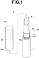
- FIG. 1 is a perspective view that illustrates the outer appearance of a feed out container 1 according to an embodiment of the present invention
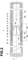
- FIG. 2 is a cross sectional side view of the feed out container 1 taken along a plane that includes the longitudinal axis thereof.
- the feed out container 1 is constituted by a main body portion 10 that houses a contained material M, and a lid body portion20 which is coupled with the main body portion 10 so as to cover the contained material M.
- FIG. 1 illustrates a state in which the lid body portion 20 is not coupled with the main body portion 10, that is, a lid open state.
- FIG. 2 illustrates a state in which the lid body portion 20 is coupled with the main body portion 10, that is, a lid closed state.
- the contained material M is a cosmetic for lips, which is a solid composition that contains isododecane as a type of hydrocarbon oil component and water, for example.
- the main body portion is basically constituted by: a metal main body outer sleeve 11 (skirted cylinder) formed as a cylinder with a bottom; a spiral sleeve 12 formed as a cylinder without a bottom and which is fitted into the inner circumferential surface of the main body outer sleeve 11; a rotatable sleeve 13 provided within the interior of the spiral sleeve 12 and which is relatively rotatable with respect to the spiral sleeve 12; an inner plate 14 provided within the interior of the rotatable sleeve 13 and which is capable of moving relative to the rotatable sleeve 13 in the axial direction of the sleeve; and an inner member 15 which is fitted into the inner circumferential surface of the main body outer sleeve 11 in the vicinity of an open end thereof.
- the lid body portion 20 is basically constituted by: a metal lid body outer sleeve 21 formed as a cylinder with a bottom; and a lid body inner sleeve 22 formed as a cylinder with a bottom and which is fitted into the inner circumferential surface of the lid body outer sleeve 21.
- the metal main body outer sleeve 11 is favorably formed employing aluminum, for example.
- the axis C of the sleeve is indicated by a single dotted line.
- the metal main body outer sleeve 11 does not allow hydrocarbon oil components such as isododecane or water to pass therethrough. This point also applies to the metal inner member 15 and the lid body outer sleeve 21 to be described later as well.
- the spiral sleeve 12 in the form of a cylinder without a bottom has a spiral groove etched in the inner circumferential surface thereof, and is integrated with the main body outer sleeve 11 by being fit thereinto, for example.
- Two linear grooves 13a that extend along the axis of the rotatable sleeve 13 are formed in a peripheral wall thereof at an angular interval of 180 degrees, for example.
- the inner plate 14 has a housing portion 14a that houses the contained material M at a leading end side, that is, a side opposite the bottom of the main body outer sleeve 11.
- the spiral sleeve 12 and the rotatable sleeve 13 are formed by polyacetal, for example.
- two protrusions 14b that protrude in a direction that perpendicularly intersects the axis C of the sleeve, for example, are formed on an outer peripheral surface of the inner plate 14.
- Each of these protrusions 14b passes through the linear grooves 13a of the rotatable sleeve 13, and are loosely engaged with the interior of the spiral groove of the spiral sleeve 12.
- the contained material M which is housed in the housing portion 14a of the inner plate 12 is fed out from the rotatable sleeve 13 (that is, from the inner member 15), or inversely returned to the interior of the rotatable sleeve 13.
- the spiral sleeve 12, the rotatable sleeve 13 which has the linear grooves 13a, and the protrusions 14b of the inner plate 14 constitute a feed out mechanism for feeding out the contained material M from the inner member 15.
- the inner member 15 is formed by a metal, favorably by aluminum, for example.
- the inner member 15 has a first portion 15a which is provided within the interior of the main body outer sleeve 11 and a second portion 15b that extends outward from the open end (the end toward the opening) of the main body outer sleeve 11.
- the first portion 15a is fixed to the inner circumferential surface of the main body outer sleeve 11 by being fitted therein or the like, such that at least a portion of the first portion 15a is in close contact with the main body outer sleeve throughout the entire circumference thereof.
- the second portion 15b constitutes an annular protrusion 15c which is adjacent to an open end 11a of the main body outer sleeve 11.
- a holding member 16 that holds the rotatable sleeve 13 such that it is freely rotatable while preventing movement thereof in the axial direction of the sleeve is mounted in the interior of the first portion 15a.
- a first O ring 31 is fitted about the entire periphery of a portion of the inner member 15 more toward a leading end side than the protrusion 15c.
- a second O ring 32 is fitted about a portion of the inner member 15 more toward a back end side than the protrusion 15c.
- the "back end side” refers to the side of the bottom of the main body outer sleeve 11
- the "leading end side” refers to the side of the main body outer sleeve 11 opposite the bottom thereof.
- the first O ring 31 and the second O ring 32 are formed by nitryl rubber (NBR), for example.
- NBR nitryl rubber
- the metal lid body outer sleeve 21 is favorably formed by aluminum, for example.
- the lid body inner sleeve 22 is formed by Hytrel (registered trademark), which is a type of thermoplastic polyester series elastomer. A portion of the lid body inner sleeve 22 in a length direction thereof is in close contact with the inner circumferential surface of the lid body outer sleeve 21 throughout the entire circumference thereof.
- the lid body portion 20 When the lid body portion 20 is coupled with the main body portion 10 such that the feed out container 1 is in a lid closed state, that is, the state which is illustrated in FIG. 2 , an open end 21a of the lid body outer sleeve 21 abuts the protrusion 15c of the inner member 15, and the lid body outer sleeve forms a sealed inner space S with the main body outer sleeve 11.
- the lid body portion 20 achieves its intended function. That is, the contained material M which is within the sealed inner space S is isolated from the exterior of the lid body portion 20, and volatilization of the components within the contained material M is prevented.
- the inner member 15 is of a shape having two annular protrusions that form overhangs toward the exterior in the radial direction in the vicinity of the leading end thereof to constitute a recess 15d.
- the lid closed state is maintained by a portion of the lid body inner sleeve 22 engaging the recess 15d while elastically deforming. That is, the lid body inner sleeve 22 functions to retain the lid body portion 20 on the main body portion 10. It is possible to release the coupling between the lid body portion 20 and the main body portion 10 by pulling the lid body portion 20 from the main body portion 10 with a predetermined degree of force.
- the contained material M is a cosmetic for lips that contains isododecane, which is a type of hydrocarbon oil component, and water. Isododecane and water (hereinafter, referred to as "volatile components”) may volatilize.
- the aforementioned Hytrel is a material that functions well to prevent passage of these volatile components. Therefore, passage of the volatile components through the lid body inner sleeve 22 and escape of the volatile components toward the side of the open end 21a of the lid body outer sleeve 21 is suppressed in the lid closed state.
- a portion of the lid body inner sleeve 22 in the length direction thereof is in close contact with the inner circumferential surface of the lid body outer sleeve 21 throughout the entire circumference thereof. Therefore, the volatile components are also prevented from escaping toward the side of the open end 21a of the lid body outer sleeve 21 from a gap between the lid body outer sleeve 21 and the lid body inner sleeve 22 as well.
- the first O ring which is fitted about the outer periphery of the inner member 15 is interposed between the inner member 15 and the lid body outer sleeve 21 and maintains an airtight seal between the inner member 15 and the lid body outer sleeve. Therefore, even if the volatile components are in a state in which they are capable of escaping toward the open end 21a of the lid body outer sleeve 21, the volatile components are blocked by the O ring 31, and cannot leak to the exterior of the lid body portion 20.
- an aperture 14c that operates as an air venting channel when the contained material M is housed in the inner plate 14 is formed in a portion that corresponds to the bottom of the housing portion 14a, as illustrated in FIG. 2 .
- the volatile components will escape through the aperture 14c toward an open end of the inner plate 14, move toward the side toward the inner member 15, and escape to the exterior from between the inner member 15 and the main body outer sleeve 11.
- the second O ring 32 is fitted about a portion of the inner member 15 more toward the back end side than the protrusion 15c in the present embodiment, as described previously.
- the second O ring 32 maintains an airtight seal between the inner member 15 and the main body outer sleeve 11. Therefore, a channel through which the volatile components may pass through is prevented from being formed between the inner member 15 and the main body outer sleeve 11.
- the experiments employed a total of nine samples of feed out containers that include the feed out container 1 of the embodiment described above.
- the nine sample feed out containers were all of the same shape.
- the inner diameters of the main outer sleeves 11 and the lid body outer sleeves 21 were 12.1 mm, and the distances from an inner bottom surface of the main body outer sleeves 11 to an inner bottom surface of the lid body inner sleeves 22 were 77.0 mm in the lid closed state.
- the outer diameters of the contained materials M were 9.6 mm and the total lengths thereof were 40.7 mm in an initial state.
- the contained materials M were the same as that of the embodiment described above.
- the feed out containers of the nine samples were placed in a static state in a 50°C environment while maintaining a lid closed state, and how the weight of the contained materials M therein changed over time were measured.
- a feed out container which was filled with the contained material M and a feed out container which was not filled with the contained material M were prepared for each of the samples. The weight of the latter was subtracted from the weight of the former at each point in time, and the differences were designated as the weights of the contained materials M.
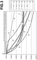
- the horizontal axis represents elapsed time from an initial state in units of weeks (W), and the horizontal axis represents the rate of decrease in the weights of the contained materials M from the initial state.
- the rates of decrease in weights indicate how many percent the weight has decreased from the initial state. For example, "-5.00%” indicates that the weight of the contained material M has decreased by 5.00% from the initial state. It can be said that volatilization of the volatile components was more positively prevented the smaller the rate of decrease in weight is.
- Sample 9 which is the feed out container 1 according to the embodiment described above, had the most gradual progression of the decrease in the amount of the contained material over time.
- the rate of decrease in the weight of the contained material at a point in time at which 32 weeks had elapsed from the initial state (hereinafter, this point in time will be referred to as "final point in time"), is the smallest among all of the nine samples.
- Sample 8 which differs from Sample 9 only in the point that the second O ring 32 is not provided, also exhibited substantially the same contained material weight decrease property as that of Sample 9.
- Samples 7 through 9 described above are feed out containers according to the present invention.
- the decreases in the weights of the contained materials in Samples 1 through 6, which are feed out containers outside the scope of the present invention, will be considered.
- Sample 6 differs from Sample 9 only in the point that the first O ring 31 and the second O ring 32 are not provided.
- Sample 6 exhibits contained material weight decrease property similar to that of Sample 7. However, the contained material weight decrease is somewhat greater at each point of time at which measurement was conducted.
- Sample 5 differs from Sample 9 in the point that the first O ring 31 and the second O ring 32 are not provided, and also in the point that the lid body outer sleeve 21 is formed by Hytrel, not a metal. In Sample 5, the contained material weight decrease is greater at each point of time at which measurement was conducted than Sample 6.
- Samples 2, 3, and 4 respectively differ from Samples 7, 8, and 9 described above, which are feed out containers according to the present invention, only in the point that the lid body inner sleeve 22 is formed by LLDPE, not Hytrel.
- Samples 3 and 4 had a small contained material weight decrease for certain amounts of time from the initial state. However, the contained material weight decrease accelerated rapidly after approximately three weeks for Sample 4 and after approximately 10 weeks for Sample 3. The rates of decreases in weight of both Sample 3 and Sample 4 were greater than that of Sample 7 at the final point in time.
- the rapid increase in the contained material weight decrease is due to the LLDPE, which is the material of the lid body inner sleeve 22, being caused to swell by isododecane. That is, it is presumed the swelling caused the airtight properties of the lid body inner sleeve 22 to deteriorate, and that the volatile components, particularly isododecane, passed through the lid body inner sleeve 22.
- the lid body inner sleeve 22 of Sample 1 is formed by LLDPE in the same manner as Samples 2, 3, and 4 described above. Further, Sample 1 is not provided with the first O ring 31 and the second O ring 32 in the same manner as Sample 6. Sample 1 and Sample 2 exhibited substantially the same contained material weight decrease property, and the rates of decreases in weight of both of Sample 1 and Sample 2 were greater than the rate of decrease in weight of Sample 6 at the final point in time.
- Samples 8 and 9 which are feed out containers according to the present invention, had extremely gradual decreases in weight of the contained materials throughout the entire measurement period, and the rates of decrease in weight thereof at the final point in time are clearly less than those of the other samples.
- Sample 7, which is a feed out container according to the present invention had a more significant decrease in weight of the contained material than Sample 8 and Sample 9, but had a smaller rate of decrease in weight than any of Samples 1 through 6 at the final point in time.
- the feed out container 1 of the embodiment described above houses a cosmetic for lips that includes isododecante, which is a type of hydrocarbon oil component, and water as the contained material M.
- the feed out container of the present invention may house contained materials other than cosmetics for lips. Examples of contained materials other than cosmetics for lips include concealers and solid adhesive pastes.
- the present invention is particularly effective in the case that the contained material is a solid composition that includes water and a hydrocarbon.
- the present inventors compared the contained material weight decrease suppressing effect, in other words, the contained material isolating effect, of nitrile rubber (NBR), which is employed in the embodiment described above, and fluorine rubber (more specifically, a vulcanized diene polyol rubber by 3M Company), by conducting an experiment.
- NBR nitrile rubber
- fluorine rubber more specifically, a vulcanized diene polyol rubber by 3M Company
- the lid body outer sleeves 21 and the lid body inner sleeves 22 are respectively formed by aluminum and Hytrel, in the same manner as Samples 6 through 9.
- feed out containers in which both the first O ring 31 and the second O ring 32 are formed by nitril rubber hereinafter, referred to as Sample N
- Sample F feed out containers in which both the first O ring 31 and the second O ring 32 are formed by fluorine rubber
Landscapes
- Engineering & Computer Science (AREA)
- Mechanical Engineering (AREA)
- Closures For Containers (AREA)
Abstract
Description
- The present invention is related to a feed out container. More specifically, the present invention is related to a feed out container which has a main body portion that houses a contained material and a lid body portion to be coupled with the main body portion, and is configured to feed out the contained material from the main body portion.
- Conventionally, a feed out container equipped with a main body outer sleeve which is formed as a cylinder with a bottom, an inner member of which a portion extends out from the main body outer sleeve, an inner plate that holds a solid contained material and is provided within the main body outer sleeve such that it is capable of moving in the axial direction of the sleeve, a lid body outer sleeve which is formed substantially as a cylinder with a bottom and defines a closed space in the interior thereof together with the main body outer sleeve, a lid body inner cylinder provided within the interior of the lid body outer sleeve, and a feed out mechanism that moves the inner plate in the axial direction of the sleeve to feed out the contained material from the inner member is known as a container for housing a solid composition such as a cosmetic for lips, as disclosed in
Patent Document 1. - In the aforementioned feed out container, the main body outer sleeve, the inner member, and the lid body outer sleeve are often formed by a metal such as aluminum, to prevent volatilization of the contained material, etc. In addition, the inner member has a first portion provided within the interior of the main body outer sleeve and a second portion that extends outward from an open end of the main body outer sleeve, that is, an end surface at an open end, in many cases. At least a portion of the first portion is in close contact with the main body outer sleeve throughout the entire circumference thereof, and the second portion constitutes an annular protrusion which is adjacent to the open end of the main body outer sleeve. The lid body outer sleeve is configured such that it defines the aforementioned closed space by being in a state in which an open end thereof abuts the protrusion of the inner member (lid closed state). In addition, the lid body inner cylinder is configured such that at least a portion thereof is in close contact with the lid body outer sleeve throughout the entire circumference thereof and functions to retain the inner member, in many cases.
- Meanwhile, cosmetics for lips such as lip gloss and solid lip rouge that contain a hydrocarbon such as isododecane and water are known, as disclosed in Patent Document 2, for example. Sale of this type of solid cosmetic for lips in an aspect in which it is housed in a feed out container in a manner similar to other cosmetics for lips is being considered.
-
- [Patent Document 1]
Japanese Unexamined Patent Publication No. 2009-136474 - [Patent Document 2]
Japanese Patent No. 6147897 - However, according to research conducted by the present inventors, it was found that in the case that a cosmetic for lips that contains a hydrocarbon such as isododecane and water is housed in a conventional feed out container, the weight of the cosmetic decreases significantly accompanying the passage of time, even if the lid body outer sleeve is coupled to the main body outer sleeve to be in a lid closed state.
- The present invention has been developed in view of the foregoing circumstances. It is an object of the present invention to provide a feed out container which is capable of suppressing a decrease in the amount of a contained substance when the contained substance is that which contains a hydrocarbon such as isododecane and water.
- A feed out container according to the present invention has:
- a metal main body outer sleeve formed substantially as a cylinder with a bottom;
- a metal cylindrical inner member having a first portion provided within the interior of the main body outer sleeve and a second portion that extends outward from an open end of the main body outer sleeve, at least a portion of the first portion being in close contact with the main body outer sleeve throughout the entire circumference thereof and the second portion constituting an annular protrusion adjacent to the open end of the main body outer sleeve;
- an inner plate that holds a solid contained material and is provided within the interior of the main body outer sleeve so as to be movable in an axial direction of the sleeve;
- a metal lid body outer sleeve formed substantially as a cylinder with a bottom, that defines a closed interior space with the main body outer sleeve by an end surface at an open end thereof abutting the protrusion of the inner member;
- a lid body inner sleeve provided within the interior of the lid body outer sleeve, of which at least a portion is in close contact with the lid body outer sleeve throughout the entire circumference thereof;
- a feed out mechanism that moves the inner plate in an axial direction of the sleeve to feed out the contained material from the inner member; and
- at least one of a first O ring fitted about the periphery of a portion of the inner member more toward a distal end thereof than the protrusion that maintains an airtight seal between the lid body outer sleeve and the inner member when the lid body outer sleeve is provided at a lid closed position, at which the lid body outer cylinder defines the closed interior space, and a second O ring fitted about the periphery of a portion of the inner member more toward a rear end than the protrusion to maintain an airtight seal between the inner member and the main body outer sleeve;
- the lid body inner sleeve being formed by a polyester series elastomer.
- Note that it is desirable for both of the first O ring and the second O ring to be provided. In addition, the present invention is preferably applied as a feed out container that houses a solid composition that contains water and a hydrocarbon as the contained material. Specific examples of such a solid composition include cosmetics, particularly cosmetics for lips such as solid lip rouge and lip gloss.
- The present inventors discovered that the significant loss of the amount of a contained material such as a cosmetic for lips in a conventional feed out container is caused by a lid body inner sleeve constituted by LLDPE (linear low density polyethylene) of the like swells by reacting with a hydrocarbon such as isododecane which is a component in the composition of the contained material such as a cosmetic for lips. That is, if the lid body inner sleeve swells, there are cases in which the lid body inner sleeve deforms in the radial direction toward the interior (toward the axis of the sleeve) or toward the exterior. A gap through which water and a hydrocarbon, which are volatile components of the contained material, may pass will be formed at a portion of the lid body inner sleeve which is deformed toward the interior in the radial direction. In addition, if the lid body inner sleeve swells, the lid body inner sleeve itself facilitates passage of the aforementioned volatile components, particularly a hydrocarbon such as isododecane, to pass therethrough.
- In the feed out container of the present invention, the lid body inner sleeve is constituted by a polyester series elastomer based on the aforementioned new discovery. The polyester series elastomer does not swell due to hydrocarbons such as isododecane, or swells only extremely slightly. Accordingly, in the feed out container of the present invention, volatilization of volatile components in a contained material being facilitated due to swelling of the lid body inner sleeve is prevented. As a result, it becomes possible to effectively suppress a decrease in the amount of a contained material.
- In addition, in the case that the first O ring is provided in the feed out container of the present invention, even if volatile components passes through the lid body inner sleeve or passes through the gap between the lid body inner sleeve and the lid body outer sleeve and proceeds toward the open end of the lid body outer sleeve, the volatile components are prevented from escaping the lid body outer sleeve by the O ring. As a result, it becomes possible to suppress a decrease in the amount of a contained material by this feature as well.
- Meanwhile, there may be cases in which volatile components of a contained material held by the inner plate travel toward the side of the open end of the main body outer sleeve through a space between the main body outer sleeve and the inner member, within the interior of the main body outer sleeve. In the case that the second O ring is provided in the feed out container of the present invention, it becomes possible to stop the volatile components that travel in this manner. Therefore, the volatile components can be prevented from passing through the gap and escaping from the open end of the main body outer sleeve. As a result. It becomes possible to suppress a decrease in the amount of a contained material.
- Cases in which the contained material includes water and a hydrocarbon as volatile components have been described above. However, the feed out container of the present invention is capable of preventing volatile components from escaping to the exterior of the container, thereby suppressing a decrease in the amount of the contained material, even in cases that the contained material includes volatile components other than water and a hydrocarbon.
-
-
FIG. 1 is a perspective view that illustrates a feed out container according to an embodiment of the present invention. -
FIG. 2 is a cross sectional side view of the feed out container ofFIG. 1 . -
FIG. 3 is a graph that illustrates the results of an experiment that confirmed the advantageous effects of the present invention. - Hereinafter, an embodiment of the present invention will be described with reference to the attached drawings.
FIG. 1 is a perspective view that illustrates the outer appearance of a feed outcontainer 1 according to an embodiment of the present invention, andFIG. 2 is a cross sectional side view of the feed outcontainer 1 taken along a plane that includes the longitudinal axis thereof. As illustrated in the drawings, the feed outcontainer 1 is constituted by amain body portion 10 that houses a contained material M, and a lid body portion20 which is coupled with themain body portion 10 so as to cover the contained material M. -
FIG. 1 illustrates a state in which thelid body portion 20 is not coupled with themain body portion 10, that is, a lid open state. Meanwhile,FIG. 2 illustrates a state in which thelid body portion 20 is coupled with themain body portion 10, that is, a lid closed state. Note that in the present embodiment, the contained material M is a cosmetic for lips, which is a solid composition that contains isododecane as a type of hydrocarbon oil component and water, for example. - The main body portion is basically constituted by: a metal main body outer sleeve 11 (skirted cylinder) formed as a cylinder with a bottom; a
spiral sleeve 12 formed as a cylinder without a bottom and which is fitted into the inner circumferential surface of the main bodyouter sleeve 11; arotatable sleeve 13 provided within the interior of thespiral sleeve 12 and which is relatively rotatable with respect to thespiral sleeve 12; aninner plate 14 provided within the interior of therotatable sleeve 13 and which is capable of moving relative to therotatable sleeve 13 in the axial direction of the sleeve; and aninner member 15 which is fitted into the inner circumferential surface of the main bodyouter sleeve 11 in the vicinity of an open end thereof. Meanwhile, thelid body portion 20 is basically constituted by: a metal lid bodyouter sleeve 21 formed as a cylinder with a bottom; and a lid body inner sleeve 22 formed as a cylinder with a bottom and which is fitted into the inner circumferential surface of the lid bodyouter sleeve 21. - Hereinafter, the
main body portion 10 will be described in detail. The metal main bodyouter sleeve 11 is favorably formed employing aluminum, for example. InFIG. 2 , the axis C of the sleeve is indicated by a single dotted line. The metal main bodyouter sleeve 11 does not allow hydrocarbon oil components such as isododecane or water to pass therethrough. This point also applies to the metalinner member 15 and the lid bodyouter sleeve 21 to be described later as well. - The
spiral sleeve 12 in the form of a cylinder without a bottom has a spiral groove etched in the inner circumferential surface thereof, and is integrated with the main bodyouter sleeve 11 by being fit thereinto, for example. Twolinear grooves 13a that extend along the axis of therotatable sleeve 13 are formed in a peripheral wall thereof at an angular interval of 180 degrees, for example. Theinner plate 14 has ahousing portion 14a that houses the contained material M at a leading end side, that is, a side opposite the bottom of the main bodyouter sleeve 11. Thespiral sleeve 12 and therotatable sleeve 13 are formed by polyacetal, for example. - In addition, two
protrusions 14b that protrude in a direction that perpendicularly intersects the axis C of the sleeve, for example, are formed on an outer peripheral surface of theinner plate 14. Each of theseprotrusions 14b passes through thelinear grooves 13a of therotatable sleeve 13, and are loosely engaged with the interior of the spiral groove of thespiral sleeve 12. When therotatable sleeve 13 relatively rotates with respect to the main bodyouter sleeve 11, that is, with respect to thespiral sleeve 12, theinner plate 14 moves linearly within the main bodyouter sleeve 11 in a direction along the axis C of the sleeve. The direction of this linear movement changes according to the direction of the relative rotation. - Accordingly, by relatively rotating the
rotatable sleeve 13 with respect to thespiral sleeve 12, the contained material M which is housed in thehousing portion 14a of theinner plate 12 is fed out from the rotatable sleeve 13 (that is, from the inner member 15), or inversely returned to the interior of therotatable sleeve 13. As described above, in the present embodiment, thespiral sleeve 12, therotatable sleeve 13 which has thelinear grooves 13a, and theprotrusions 14b of theinner plate 14 constitute a feed out mechanism for feeding out the contained material M from theinner member 15. - The
inner member 15 is formed by a metal, favorably by aluminum, for example. Theinner member 15 has afirst portion 15a which is provided within the interior of the main bodyouter sleeve 11 and asecond portion 15b that extends outward from the open end (the end toward the opening) of the main bodyouter sleeve 11. Thefirst portion 15a is fixed to the inner circumferential surface of the main bodyouter sleeve 11 by being fitted therein or the like, such that at least a portion of thefirst portion 15a is in close contact with the main body outer sleeve throughout the entire circumference thereof. Meanwhile, thesecond portion 15b constitutes anannular protrusion 15c which is adjacent to anopen end 11a of the main bodyouter sleeve 11. Note that a holdingmember 16 that holds therotatable sleeve 13 such that it is freely rotatable while preventing movement thereof in the axial direction of the sleeve is mounted in the interior of thefirst portion 15a. - A
first O ring 31 is fitted about the entire periphery of a portion of theinner member 15 more toward a leading end side than theprotrusion 15c. In addition, asecond O ring 32 is fitted about a portion of theinner member 15 more toward a back end side than theprotrusion 15c. Note that the "back end side" refers to the side of the bottom of the main bodyouter sleeve 11, and the "leading end side" refers to the side of the main bodyouter sleeve 11 opposite the bottom thereof. Thefirst O ring 31 and thesecond O ring 32 are formed by nitryl rubber (NBR), for example. Thesecond O ring 32 maintains an airtight seal between theinner member 15 and the main bodyouter sleeve 11. - Next the
lid body portion 20 will be described in detail. The metal lid bodyouter sleeve 21 is favorably formed by aluminum, for example. The lid body inner sleeve 22 is formed by Hytrel (registered trademark), which is a type of thermoplastic polyester series elastomer. A portion of the lid body inner sleeve 22 in a length direction thereof is in close contact with the inner circumferential surface of the lid bodyouter sleeve 21 throughout the entire circumference thereof. - Next, the operative effects of the above configuration will be described. When the
lid body portion 20 is coupled with themain body portion 10 such that the feed outcontainer 1 is in a lid closed state, that is, the state which is illustrated inFIG. 2 , anopen end 21a of the lid bodyouter sleeve 21 abuts theprotrusion 15c of theinner member 15, and the lid body outer sleeve forms a sealed inner space S with the main bodyouter sleeve 11. In the lid closed state, thelid body portion 20 achieves its intended function. That is, the contained material M which is within the sealed inner space S is isolated from the exterior of thelid body portion 20, and volatilization of the components within the contained material M is prevented. - Note that the
inner member 15 is of a shape having two annular protrusions that form overhangs toward the exterior in the radial direction in the vicinity of the leading end thereof to constitute arecess 15d. The lid closed state is maintained by a portion of the lid body inner sleeve 22 engaging therecess 15d while elastically deforming. That is, the lid body inner sleeve 22 functions to retain thelid body portion 20 on themain body portion 10. It is possible to release the coupling between thelid body portion 20 and themain body portion 10 by pulling thelid body portion 20 from themain body portion 10 with a predetermined degree of force. - Prevention of volatilization of components within the contained material M will be described in greater detail. As described earlier, the contained material M is a cosmetic for lips that contains isododecane, which is a type of hydrocarbon oil component, and water. Isododecane and water (hereinafter, referred to as "volatile components") may volatilize. The aforementioned Hytrel is a material that functions well to prevent passage of these volatile components. Therefore, passage of the volatile components through the lid body inner sleeve 22 and escape of the volatile components toward the side of the
open end 21a of the lid bodyouter sleeve 21 is suppressed in the lid closed state. In addition, a portion of the lid body inner sleeve 22 in the length direction thereof is in close contact with the inner circumferential surface of the lid bodyouter sleeve 21 throughout the entire circumference thereof. Therefore, the volatile components are also prevented from escaping toward the side of theopen end 21a of the lid bodyouter sleeve 21 from a gap between the lid bodyouter sleeve 21 and the lid body inner sleeve 22 as well. - Further, in the lid closed state illustrated in
FIG. 2 , the first O ring which is fitted about the outer periphery of theinner member 15 is interposed between theinner member 15 and the lid bodyouter sleeve 21 and maintains an airtight seal between theinner member 15 and the lid body outer sleeve. Therefore, even if the volatile components are in a state in which they are capable of escaping toward theopen end 21a of the lid bodyouter sleeve 21, the volatile components are blocked by theO ring 31, and cannot leak to the exterior of thelid body portion 20. - Note that an
aperture 14c that operates as an air venting channel when the contained material M is housed in theinner plate 14 is formed in a portion that corresponds to the bottom of thehousing portion 14a, as illustrated inFIG. 2 . There is a possibility that the volatile components will escape through theaperture 14c toward an open end of theinner plate 14, move toward the side toward theinner member 15, and escape to the exterior from between theinner member 15 and the main bodyouter sleeve 11. Taking this possibility into consideration, thesecond O ring 32 is fitted about a portion of theinner member 15 more toward the back end side than theprotrusion 15c in the present embodiment, as described previously. Thesecond O ring 32 maintains an airtight seal between theinner member 15 and the main bodyouter sleeve 11. Therefore, a channel through which the volatile components may pass through is prevented from being formed between theinner member 15 and the main bodyouter sleeve 11. - Next, the results of an experiment that confirmed that volatilization of the volatile components was prevented will be described. The experiments employed a total of nine samples of feed out containers that include the feed out
container 1 of the embodiment described above. The nine sample feed out containers were all of the same shape. The inner diameters of the mainouter sleeves 11 and the lid bodyouter sleeves 21 were 12.1 mm, and the distances from an inner bottom surface of the main bodyouter sleeves 11 to an inner bottom surface of the lid body inner sleeves 22 were 77.0 mm in the lid closed state. In addition, the outer diameters of the contained materials M were 9.6 mm and the total lengths thereof were 40.7 mm in an initial state. The contained materials M were the same as that of the embodiment described above. That is, the contained materials M were cosmetics for lips that contain isododecane and water. The configurations of the principal portions of the nine sample feed out containers were as shown in Table 1 below.[Table 1] Sample Material of Lid Body O Rings Number Outer Sleeve/Inner Sleeve First O Ring Second O Ring 1 AL/LLDPE n/a n/a 2 AL/LLDPE n/a Yes 3 AL/LLDPE Yes n/a 4 AL/LLDPE Yes Yes 5 Hytrel n/a n/a 6 AL/Hytrel n/a n/a 7 AL/Hytrel n/a Yes 8 AL/Hytrel Yes n/a 9 AL/Hytrel Yes Yes - In Table 1, the nine samples are respectively denoted by
Sample Numbers 1 through 9. Each of the Sample Numbers are indicated as circled numbers inFIG. 3 . In addition, in the Material of Lid Body column, "AL" represents aluminum, and "LLDPE" represents linear low density polyethylene, which is a material that is commonly employed as the material of a lid body inner sleeve in this type of cosmetic feed out container. - In the experiment, the feed out containers of the nine samples were placed in a static state in a 50°C environment while maintaining a lid closed state, and how the weight of the contained materials M therein changed over time were measured. In this experiment, a feed out container which was filled with the contained material M and a feed out container which was not filled with the contained material M were prepared for each of the samples. The weight of the latter was subtracted from the weight of the former at each point in time, and the differences were designated as the weights of the contained materials M.
- The results of this experiment are illustrated in
FIG. 3 . InFIG. 3 , the horizontal axis represents elapsed time from an initial state in units of weeks (W), and the horizontal axis represents the rate of decrease in the weights of the contained materials M from the initial state. The rates of decrease in weights indicate how many percent the weight has decreased from the initial state. For example, "-5.00%" indicates that the weight of the contained material M has decreased by 5.00% from the initial state. It can be said that volatilization of the volatile components was more positively prevented the smaller the rate of decrease in weight is. - The measurement results of
FIG. 3 will be considered. Sample 9, which is the feed outcontainer 1 according to the embodiment described above, had the most gradual progression of the decrease in the amount of the contained material over time. The rate of decrease in the weight of the contained material at a point in time at which 32 weeks had elapsed from the initial state (hereinafter, this point in time will be referred to as "final point in time"), is the smallest among all of the nine samples.Sample 8, which differs from Sample 9 only in the point that thesecond O ring 32 is not provided, also exhibited substantially the same contained material weight decrease property as that of Sample 9. In contrast, in Sample 7, which differs from Sample 9 only in the point that thefirst O ring 31 is not provided, the progression of the decrease in the amount of the contained material over time is clearly more rapid compared to Sample 9, and the rate of decrease in the weight of the contained material at the final point in time is approximately two times that of Sample 9. Based on the above, it can be said that if only one of thefirst O ring 31 and thesecond O ring 32 are to be provided, it is more desirable for thefirst O ring 31 to be provided. - Samples 7 through 9 described above are feed out containers according to the present invention. Next, the decreases in the weights of the contained materials in
Samples 1 through 6, which are feed out containers outside the scope of the present invention, will be considered.Sample 6 differs from Sample 9 only in the point that thefirst O ring 31 and thesecond O ring 32 are not provided. Sample 6 exhibits contained material weight decrease property similar to that of Sample 7. However, the contained material weight decrease is somewhat greater at each point of time at which measurement was conducted.Sample 5 differs from Sample 9 in the point that thefirst O ring 31 and thesecond O ring 32 are not provided, and also in the point that the lid bodyouter sleeve 21 is formed by Hytrel, not a metal. InSample 5, the contained material weight decrease is greater at each point of time at which measurement was conducted thanSample 6. -
Samples Samples 7, 8, and 9 described above, which are feed out containers according to the present invention, only in the point that the lid body inner sleeve 22 is formed by LLDPE, not Hytrel.Samples Sample 4 and after approximately 10 weeks forSample 3. The rates of decreases in weight of bothSample 3 andSample 4 were greater than that of Sample 7 at the final point in time. - It is presumed that the rapid increase in the contained material weight decrease is due to the LLDPE, which is the material of the lid body inner sleeve 22, being caused to swell by isododecane. That is, it is presumed the swelling caused the airtight properties of the lid body inner sleeve 22 to deteriorate, and that the volatile components, particularly isododecane, passed through the lid body inner sleeve 22.
- The lid body inner sleeve 22 of
Sample 1 is formed by LLDPE in the same manner asSamples Sample 1 is not provided with thefirst O ring 31 and thesecond O ring 32 in the same manner asSample 6.Sample 1 and Sample 2 exhibited substantially the same contained material weight decrease property, and the rates of decreases in weight of both ofSample 1 and Sample 2 were greater than the rate of decrease in weight ofSample 6 at the final point in time. - As described above,
Samples 8 and 9, which are feed out containers according to the present invention, had extremely gradual decreases in weight of the contained materials throughout the entire measurement period, and the rates of decrease in weight thereof at the final point in time are clearly less than those of the other samples. In addition, Sample 7, which is a feed out container according to the present invention, had a more significant decrease in weight of the contained material thanSample 8 and Sample 9, but had a smaller rate of decrease in weight than any ofSamples 1 through 6 at the final point in time. - Note that the feed out
container 1 of the embodiment described above houses a cosmetic for lips that includes isododecante, which is a type of hydrocarbon oil component, and water as the contained material M. However, the feed out container of the present invention may house contained materials other than cosmetics for lips. Examples of contained materials other than cosmetics for lips include concealers and solid adhesive pastes. The present invention is particularly effective in the case that the contained material is a solid composition that includes water and a hydrocarbon. - Next, preferred materials for the O rings which are employed in the feed out container of the present invention will be described. The present inventors compared the contained material weight decrease suppressing effect, in other words, the contained material isolating effect, of nitrile rubber (NBR), which is employed in the embodiment described above, and fluorine rubber (more specifically, a vulcanized diene polyol rubber by 3M Company), by conducting an experiment. The shapes of the feed out containers which were utilized in this experiment are basically the same as that of the feed out
container 1 of the embodiment described above and is illustrated inFIG. 2 . However, the feed out containers which were utilized in the experiment differ from the feed outcontainer 1 in the point that theinner members 15 thereof are formed by POM (polyacetal), not aluminum, as shown in Table 2 below. In addition, the lid bodyouter sleeves 21 and the lid body inner sleeves 22 are respectively formed by aluminum and Hytrel, in the same manner asSamples 6 through 9. For the sake of comparison, feed out containers in which both thefirst O ring 31 and thesecond O ring 32 are formed by nitril rubber (hereinafter, referred to as Sample N), and feed out containers in which both thefirst O ring 31 and thesecond O ring 32 are formed by fluorine rubber (hereinafter, referred to as Sample F) were produced.[Table 2] Material of Lid Body Main Body Outer Sleeve 21/Inner Sleeve 22 Inner Plate 15First O Ring 31Second O Ring 32AL/Hytrel POM NBR/Fluorine Rubber NBR - In the comparative experiment, nine feed out containers of Sample N which are filled with contained materials M, and nine feed out containers of Sample F which are filled with contained materials M were prepared. Three of each of the samples were placed in static states in environments at 25°C, 37°C, and 50°C, and the rates of decrease in the weights of the contained materials M were measured. Here, the contained materials M were the same as that of the embodiment described above, that is, the contained materials M were cosmetics for lips that contain isododecane and water. In addition, the measurements of the rates of decrease and the manner in which the rates of decrease are indicated are the same as those described previously. In this experiment, the rates of decrease were measured each week from an initial state until eight weeks (W) elapsed.
- The results of the measurements are shown in Table 3, with the results for Sample N in the upper rows, and the results for Sample F in the lower rows. Note that in Table 3, the measurement results related to each of the conditions (ambient temperatures) are average values of each of the sets of three samples. As shown below, it can be understood that Sample F had lower rates of decrease in weight, that is, higher contained material isolating effects, than Sample N under all three conditions.
-
[Table 3] Contained Material: Cosmetic for Lips Decrease Rate of Sample N (Average Value of 3 Samples for each Condition) Condition Initial 1W 2W 3W 4W 5W 6W 7W 8W 25°C 0 -0.04% -0.09% -0.12% -0.17% -0.22% -0.24% -0.29% -0.33% 37°C 0 -0.12% -0.26% -0.32% -0.42% -0.56% -0.63% -0.76% -0.89% 50°C 0 -0.21% -0.52% -0.77% -1.07% -1.39% -1.55% -1.88% -2.22% Decrease Rate of Sample F (Average Value of 3 Samples for each Condition) Condition Initial 1W 2W 3W 4W 5W 6W 7W 8W 25°C 0 -0.01% -0.01 % -0.02% -0.03% -0.04% -0.04% -0.06% -0.07% 37°C 0 -0.06% -0.10% -0.13% -0.15% -0.19% -0.21% -0.21% -0.28% 50°C 0 -0.04% -0.15% -0.18% -0.25% -0.30% -0.34% -0.34% -0.49% -
- 1
- feed out container
- 10
- main body portion
- 11
- main body outer sleeve
- 11a
- open end of main body outer sleeve
- 12
- spiral sleeve
- 13
- rotatable sleeve
- 14
- inner plate
- 15
- inner member
- 15a
- first portion of inner member
- 15b
- second portion of inner member
- 15c
- protrusion of inner member
- 16
- holding member
- 20
- lid body portion
- 21
- lid body outer sleeve
- 21a
- open end of lid body outer sleeve
- 22
- lid body inner sleeve
- 31
- first O ring
- 32
- second O ring
Claims (6)
- A feed out container comprising:a metal main body outer sleeve formed substantially as a cylinder with a bottom;a metal cylindrical inner member having a first portion provided within the interior of the main body outer sleeve and a second portion that extends outward from an open end of the main body outer sleeve, at least a portion of the first portion being in close contact with the main body outer sleeve throughout the entire circumference thereof and the second portion constituting an annular protrusion adjacent to the open end of the main body outer sleeve;an inner plate that holds a solid contained material and is provided within the interior of the main body outer sleeve so as to be movable in an axial direction of the sleeve;a metal lid body outer sleeve formed substantially as a cylinder with a bottom, that defines a closed interior space with the main body outer sleeve by an end surface at an open end thereof abutting the protrusion;a lid body inner sleeve provided within the interior of the lid body outer sleeve, of which at least a portion is in close contact with the lid body outer sleeve throughout the entire circumference thereof;a feed out mechanism that moves the inner plate in an axial direction of the sleeve to feed out the contained material from the inner member; andat least one of a first O ring fitted about the periphery of a portion of the inner member more toward a distal end thereof than the protrusion that maintains an airtight seal between the lid body outer sleeve and the inner member when the lid body outer sleeve is provided at a lid closed position, at which the lid body outer cylinder defines the closed interior space, and a second O ring fitted about the periphery of a portion of the inner member more toward a rear end than the protrusion to maintain an airtight seal between the inner member and the main body outer sleeve;the lid body inner sleeve being formed by a polyester series elastomer.
- The feed out container as defined in Claim 1, wherein:
both of the first O ring and the second O ring are provided. - The feed out container as defined in either one of Claim 1 and Claim 2, wherein:
the O ring which is fitted about the inner member is formed by a fluorine rubber. - The feed out container as defined in any one of Claims 1 through 3, wherein:
the contained material is a solid composition that contains water and a hydrocarbon. - The feed out container as defined in Claim 4, wherein:
the solid composition is a cosmetic. - The feed out container as defined in Claim 5, wherein:
the cosmetic is a cosmetic for lips.
Applications Claiming Priority (2)
| Application Number | Priority Date | Filing Date | Title |
|---|---|---|---|
| JP2019065405 | 2019-03-29 | ||
| PCT/JP2020/012695 WO2020203408A1 (en) | 2019-03-29 | 2020-03-23 | Twist-up container |
Publications (3)
| Publication Number | Publication Date |
|---|---|
| EP3949800A1 true EP3949800A1 (en) | 2022-02-09 |
| EP3949800A4 EP3949800A4 (en) | 2022-12-28 |
| EP3949800B1 EP3949800B1 (en) | 2025-03-05 |
Family
ID=72667704
Family Applications (1)
| Application Number | Title | Priority Date | Filing Date |
|---|---|---|---|
| EP20785086.8A Active EP3949800B1 (en) | 2019-03-29 | 2020-03-23 | Twist-up container |
Country Status (5)
| Country | Link |
|---|---|
| US (1) | US11896110B2 (en) |
| EP (1) | EP3949800B1 (en) |
| JP (1) | JP7567123B2 (en) |
| CN (1) | CN113631061B (en) |
| WO (1) | WO2020203408A1 (en) |
Families Citing this family (2)
| Publication number | Priority date | Publication date | Assignee | Title |
|---|---|---|---|---|
| USD1010229S1 (en) * | 2021-08-02 | 2024-01-02 | Shiseido Company, Limited | Lipstick case |
| US12329265B2 (en) * | 2022-08-19 | 2025-06-17 | Elc Management Llc | Cosmetic product container and retention mechanism |
Family Cites Families (18)
| Publication number | Priority date | Publication date | Assignee | Title |
|---|---|---|---|---|
| JPS5423024A (en) | 1977-07-21 | 1979-02-21 | Tanaka Precious Metal Ind | Silver tin oxide electric contact point material |
| JPH0627912Y2 (en) * | 1989-11-16 | 1994-07-27 | 横浜エイロクイップ株式会社 | Refraction tube fitting |
| US5197814A (en) * | 1991-06-24 | 1993-03-30 | Elizabeth Arden Co., Division Of Conopco, Inc. | Lipstick article |
| CN1066621C (en) | 1994-07-08 | 2001-06-06 | 株式会社希丹 | A cosmetic container |
| JP2791653B2 (en) * | 1995-10-31 | 1998-08-27 | 株式会社ヒダン | Cosmetic container |
| FR2750302B1 (en) * | 1996-06-26 | 1998-08-07 | Oreal | STICK HOLDER CUP FOR A LIP PRODUCT STICK AND CASE SO EQUIPPED |
| US5860755A (en) * | 1997-03-24 | 1999-01-19 | Bunk; Carole | Lipstick holder with mirror |
| FR2806273B1 (en) | 2000-03-16 | 2002-10-04 | Oreal | DEVICE FOR PACKAGING AND APPLYING A COSMETIC OR CARE PRODUCT |
| JP2002370934A (en) * | 2001-06-13 | 2002-12-24 | Shiseido Co Ltd | Container cosmetics |
| JP3921366B2 (en) * | 2001-09-18 | 2007-05-30 | 株式会社ヒダン | Feeding container for stick-shaped articles |
| US7086796B2 (en) * | 2003-08-01 | 2006-08-08 | Bonne Bell, Inc. | Dispensing device |
| JP3796258B2 (en) * | 2004-11-10 | 2006-07-12 | 株式会社トキワ | Liquid filling extrusion container |
| CN101674749B (en) * | 2007-03-15 | 2012-04-25 | 株式会社资生堂 | Propelling container |
| JP5133668B2 (en) | 2007-12-06 | 2013-01-30 | 株式会社 資生堂 | Stick-shaped cosmetic container |
| FR3021212B1 (en) * | 2014-05-23 | 2017-09-15 | Lvmh Rech | MUTLI-COMPOSITIONS COSMETIC PRODUCTS AND METHOD FOR THE PRODUCTION THEREOF |
| JP6785492B2 (en) * | 2016-04-28 | 2020-11-18 | 鈴野化成株式会社 | Cosmetic cartridges and cartridge-type cosmetic containers |
| JP6147897B1 (en) * | 2016-06-29 | 2017-06-14 | 株式会社 資生堂 | Oil-in-water emulsified lip cosmetic |
| CN107826448B (en) * | 2017-11-29 | 2024-05-14 | 珠海先河生物技术有限公司 | Can lid and vacuum can |
-
2020
- 2020-03-23 US US17/599,408 patent/US11896110B2/en active Active
- 2020-03-23 JP JP2021511474A patent/JP7567123B2/en active Active
- 2020-03-23 CN CN202080025120.0A patent/CN113631061B/en active Active
- 2020-03-23 EP EP20785086.8A patent/EP3949800B1/en active Active
- 2020-03-23 WO PCT/JP2020/012695 patent/WO2020203408A1/en not_active Ceased
Also Published As
| Publication number | Publication date |
|---|---|
| JPWO2020203408A1 (en) | 2020-10-08 |
| EP3949800A4 (en) | 2022-12-28 |
| CN113631061B (en) | 2024-11-05 |
| US11896110B2 (en) | 2024-02-13 |
| WO2020203408A1 (en) | 2020-10-08 |
| JP7567123B2 (en) | 2024-10-16 |
| CN113631061A (en) | 2021-11-09 |
| US20220183445A1 (en) | 2022-06-16 |
| EP3949800B1 (en) | 2025-03-05 |
Similar Documents
| Publication | Publication Date | Title |
|---|---|---|
| EP3949800B1 (en) | Twist-up container | |
| EP2527695B1 (en) | Sealed structure | |
| JP5561660B2 (en) | Plain bearing | |
| JP2000060637A (en) | Bar-shaped article storage device with excessive pressure absorption mechanism | |
| EP3434143A1 (en) | Dispenser for storing and advancing a product | |
| EP3546775B1 (en) | Sintered bearing | |
| US20170122438A1 (en) | Sealing device | |
| KR101192821B1 (en) | Bar-like cosmetic delivering container | |
| KR20200056425A (en) | Syringe gasket prevention mechanism | |
| CN110621888B (en) | Fluid pressure cylinder | |
| EP1892444B1 (en) | Lip type seal | |
| EP3135154A1 (en) | Antibiotic mascara vessel having door function | |
| US20040144605A1 (en) | Piston-cylinder unit | |
| CN114321186A (en) | Seals for bearing units | |
| EP1293146A2 (en) | Thrust-out type container for a rod-like article | |
| US11231068B2 (en) | Slide bearing | |
| US20100201052A1 (en) | Gas Spring | |
| US20180187783A1 (en) | Radially displaceable seal assembly for a shaft | |
| EP3988821B1 (en) | Sealing device | |
| US3712517A (en) | Triple seal valve | |
| EP3670976B1 (en) | Sealing device | |
| US7478981B2 (en) | Concealed glandular seal | |
| JP6768582B2 (en) | Coating container that weighs and applies the contents | |
| JP2000046196A (en) | Oil seal retaining device | |
| JPS62261763A (en) | Contact type end face seal |
Legal Events
| Date | Code | Title | Description |
|---|---|---|---|
| STAA | Information on the status of an ep patent application or granted ep patent |
Free format text: STATUS: THE INTERNATIONAL PUBLICATION HAS BEEN MADE |
|
| PUAI | Public reference made under article 153(3) epc to a published international application that has entered the european phase |
Free format text: ORIGINAL CODE: 0009012 |
|
| STAA | Information on the status of an ep patent application or granted ep patent |
Free format text: STATUS: REQUEST FOR EXAMINATION WAS MADE |
|
| 17P | Request for examination filed |
Effective date: 20211005 |
|
| AK | Designated contracting states |
Kind code of ref document: A1 Designated state(s): AL AT BE BG CH CY CZ DE DK EE ES FI FR GB GR HR HU IE IS IT LI LT LU LV MC MK MT NL NO PL PT RO RS SE SI SK SM TR |
|
| DAV | Request for validation of the european patent (deleted) | ||
| DAX | Request for extension of the european patent (deleted) | ||
| A4 | Supplementary search report drawn up and despatched |
Effective date: 20221129 |
|
| RIC1 | Information provided on ipc code assigned before grant |
Ipc: B65D 53/02 20060101ALI20221123BHEP Ipc: A45D 40/06 20060101ALI20221123BHEP Ipc: A45D 40/00 20060101AFI20221123BHEP |
|
| GRAP | Despatch of communication of intention to grant a patent |
Free format text: ORIGINAL CODE: EPIDOSNIGR1 |
|
| STAA | Information on the status of an ep patent application or granted ep patent |
Free format text: STATUS: GRANT OF PATENT IS INTENDED |
|
| INTG | Intention to grant announced |
Effective date: 20240613 |
|
| GRAJ | Information related to disapproval of communication of intention to grant by the applicant or resumption of examination proceedings by the epo deleted |
Free format text: ORIGINAL CODE: EPIDOSDIGR1 |
|
| STAA | Information on the status of an ep patent application or granted ep patent |
Free format text: STATUS: REQUEST FOR EXAMINATION WAS MADE |
|
| GRAP | Despatch of communication of intention to grant a patent |
Free format text: ORIGINAL CODE: EPIDOSNIGR1 |
|
| STAA | Information on the status of an ep patent application or granted ep patent |
Free format text: STATUS: GRANT OF PATENT IS INTENDED |
|
| INTC | Intention to grant announced (deleted) | ||
| INTG | Intention to grant announced |
Effective date: 20241010 |
|
| GRAS | Grant fee paid |
Free format text: ORIGINAL CODE: EPIDOSNIGR3 |
|
| GRAA | (expected) grant |
Free format text: ORIGINAL CODE: 0009210 |
|
| STAA | Information on the status of an ep patent application or granted ep patent |
Free format text: STATUS: THE PATENT HAS BEEN GRANTED |
|
| P01 | Opt-out of the competence of the unified patent court (upc) registered |
Free format text: CASE NUMBER: APP_68545/2024 Effective date: 20241230 |
|
| AK | Designated contracting states |
Kind code of ref document: B1 Designated state(s): AL AT BE BG CH CY CZ DE DK EE ES FI FR GB GR HR HU IE IS IT LI LT LU LV MC MK MT NL NO PL PT RO RS SE SI SK SM TR |
|
| REG | Reference to a national code |
Ref country code: GB Ref legal event code: FG4D |
|
| REG | Reference to a national code |
Ref country code: CH Ref legal event code: EP |
|
| REG | Reference to a national code |
Ref country code: IE Ref legal event code: FG4D |
|
| REG | Reference to a national code |
Ref country code: DE Ref legal event code: R096 Ref document number: 602020047282 Country of ref document: DE |
|
| PG25 | Lapsed in a contracting state [announced via postgrant information from national office to epo] |
Ref country code: RS Free format text: LAPSE BECAUSE OF FAILURE TO SUBMIT A TRANSLATION OF THE DESCRIPTION OR TO PAY THE FEE WITHIN THE PRESCRIBED TIME-LIMIT Effective date: 20250605 |
|
| PG25 | Lapsed in a contracting state [announced via postgrant information from national office to epo] |
Ref country code: FI Free format text: LAPSE BECAUSE OF FAILURE TO SUBMIT A TRANSLATION OF THE DESCRIPTION OR TO PAY THE FEE WITHIN THE PRESCRIBED TIME-LIMIT Effective date: 20250305 |
|
| REG | Reference to a national code |
Ref country code: NL Ref legal event code: MP Effective date: 20250305 |
|
| PG25 | Lapsed in a contracting state [announced via postgrant information from national office to epo] |
Ref country code: ES Free format text: LAPSE BECAUSE OF FAILURE TO SUBMIT A TRANSLATION OF THE DESCRIPTION OR TO PAY THE FEE WITHIN THE PRESCRIBED TIME-LIMIT Effective date: 20250305 |
|
| REG | Reference to a national code |
Ref country code: LT Ref legal event code: MG9D |
|
| PG25 | Lapsed in a contracting state [announced via postgrant information from national office to epo] |
Ref country code: NO Free format text: LAPSE BECAUSE OF FAILURE TO SUBMIT A TRANSLATION OF THE DESCRIPTION OR TO PAY THE FEE WITHIN THE PRESCRIBED TIME-LIMIT Effective date: 20250605 |
|
| PG25 | Lapsed in a contracting state [announced via postgrant information from national office to epo] |
Ref country code: HR Free format text: LAPSE BECAUSE OF FAILURE TO SUBMIT A TRANSLATION OF THE DESCRIPTION OR TO PAY THE FEE WITHIN THE PRESCRIBED TIME-LIMIT Effective date: 20250305 |
|
| PG25 | Lapsed in a contracting state [announced via postgrant information from national office to epo] |
Ref country code: LV Free format text: LAPSE BECAUSE OF FAILURE TO SUBMIT A TRANSLATION OF THE DESCRIPTION OR TO PAY THE FEE WITHIN THE PRESCRIBED TIME-LIMIT Effective date: 20250305 |
|
| PGFP | Annual fee paid to national office [announced via postgrant information from national office to epo] |
Ref country code: FR Payment date: 20250429 Year of fee payment: 6 |
|
| PG25 | Lapsed in a contracting state [announced via postgrant information from national office to epo] |
Ref country code: GR Free format text: LAPSE BECAUSE OF FAILURE TO SUBMIT A TRANSLATION OF THE DESCRIPTION OR TO PAY THE FEE WITHIN THE PRESCRIBED TIME-LIMIT Effective date: 20250606 Ref country code: BG Free format text: LAPSE BECAUSE OF FAILURE TO SUBMIT A TRANSLATION OF THE DESCRIPTION OR TO PAY THE FEE WITHIN THE PRESCRIBED TIME-LIMIT Effective date: 20250305 |
|
| REG | Reference to a national code |
Ref country code: AT Ref legal event code: MK05 Ref document number: 1772062 Country of ref document: AT Kind code of ref document: T Effective date: 20250305 |
|
| PG25 | Lapsed in a contracting state [announced via postgrant information from national office to epo] |
Ref country code: NL Free format text: LAPSE BECAUSE OF FAILURE TO SUBMIT A TRANSLATION OF THE DESCRIPTION OR TO PAY THE FEE WITHIN THE PRESCRIBED TIME-LIMIT Effective date: 20250305 |
|
| PG25 | Lapsed in a contracting state [announced via postgrant information from national office to epo] |
Ref country code: SE Free format text: LAPSE BECAUSE OF FAILURE TO SUBMIT A TRANSLATION OF THE DESCRIPTION OR TO PAY THE FEE WITHIN THE PRESCRIBED TIME-LIMIT Effective date: 20250305 |
|
| REG | Reference to a national code |
Ref country code: DE Ref legal event code: R119 Ref document number: 602020047282 Country of ref document: DE |
|
| PG25 | Lapsed in a contracting state [announced via postgrant information from national office to epo] |
Ref country code: SM Free format text: LAPSE BECAUSE OF FAILURE TO SUBMIT A TRANSLATION OF THE DESCRIPTION OR TO PAY THE FEE WITHIN THE PRESCRIBED TIME-LIMIT Effective date: 20250305 |
|
| PG25 | Lapsed in a contracting state [announced via postgrant information from national office to epo] |
Ref country code: PT Free format text: LAPSE BECAUSE OF FAILURE TO SUBMIT A TRANSLATION OF THE DESCRIPTION OR TO PAY THE FEE WITHIN THE PRESCRIBED TIME-LIMIT Effective date: 20250707 |
|
| PG25 | Lapsed in a contracting state [announced via postgrant information from national office to epo] |
Ref country code: IT Free format text: LAPSE BECAUSE OF FAILURE TO SUBMIT A TRANSLATION OF THE DESCRIPTION OR TO PAY THE FEE WITHIN THE PRESCRIBED TIME-LIMIT Effective date: 20250305 Ref country code: PL Free format text: LAPSE BECAUSE OF FAILURE TO SUBMIT A TRANSLATION OF THE DESCRIPTION OR TO PAY THE FEE WITHIN THE PRESCRIBED TIME-LIMIT Effective date: 20250305 |
|
| PG25 | Lapsed in a contracting state [announced via postgrant information from national office to epo] |
Ref country code: AT Free format text: LAPSE BECAUSE OF FAILURE TO SUBMIT A TRANSLATION OF THE DESCRIPTION OR TO PAY THE FEE WITHIN THE PRESCRIBED TIME-LIMIT Effective date: 20250305 |
|
| PG25 | Lapsed in a contracting state [announced via postgrant information from national office to epo] |
Ref country code: CZ Free format text: LAPSE BECAUSE OF FAILURE TO SUBMIT A TRANSLATION OF THE DESCRIPTION OR TO PAY THE FEE WITHIN THE PRESCRIBED TIME-LIMIT Effective date: 20250305 Ref country code: EE Free format text: LAPSE BECAUSE OF FAILURE TO SUBMIT A TRANSLATION OF THE DESCRIPTION OR TO PAY THE FEE WITHIN THE PRESCRIBED TIME-LIMIT Effective date: 20250305 |
|
| PG25 | Lapsed in a contracting state [announced via postgrant information from national office to epo] |
Ref country code: RO Free format text: LAPSE BECAUSE OF FAILURE TO SUBMIT A TRANSLATION OF THE DESCRIPTION OR TO PAY THE FEE WITHIN THE PRESCRIBED TIME-LIMIT Effective date: 20250305 |
|
| REG | Reference to a national code |
Ref country code: CH Ref legal event code: H13 Free format text: ST27 STATUS EVENT CODE: U-0-0-H10-H13 (AS PROVIDED BY THE NATIONAL OFFICE) Effective date: 20251024 |
|
| PG25 | Lapsed in a contracting state [announced via postgrant information from national office to epo] |
Ref country code: SK Free format text: LAPSE BECAUSE OF FAILURE TO SUBMIT A TRANSLATION OF THE DESCRIPTION OR TO PAY THE FEE WITHIN THE PRESCRIBED TIME-LIMIT Effective date: 20250305 |
|
| PG25 | Lapsed in a contracting state [announced via postgrant information from national office to epo] |
Ref country code: IS Free format text: LAPSE BECAUSE OF FAILURE TO SUBMIT A TRANSLATION OF THE DESCRIPTION OR TO PAY THE FEE WITHIN THE PRESCRIBED TIME-LIMIT Effective date: 20250705 |
|
| PG25 | Lapsed in a contracting state [announced via postgrant information from national office to epo] |
Ref country code: LU Free format text: LAPSE BECAUSE OF NON-PAYMENT OF DUE FEES Effective date: 20250323 |
|
| REG | Reference to a national code |
Ref country code: BE Ref legal event code: MM Effective date: 20250331 |
|
| PG25 | Lapsed in a contracting state [announced via postgrant information from national office to epo] |
Ref country code: MC Free format text: LAPSE BECAUSE OF FAILURE TO SUBMIT A TRANSLATION OF THE DESCRIPTION OR TO PAY THE FEE WITHIN THE PRESCRIBED TIME-LIMIT Effective date: 20250305 |
|
| PG25 | Lapsed in a contracting state [announced via postgrant information from national office to epo] |
Ref country code: DE Free format text: LAPSE BECAUSE OF NON-PAYMENT OF DUE FEES Effective date: 20251001 |
|
| PLBE | No opposition filed within time limit |
Free format text: ORIGINAL CODE: 0009261 |
|
| STAA | Information on the status of an ep patent application or granted ep patent |
Free format text: STATUS: NO OPPOSITION FILED WITHIN TIME LIMIT |
|
| PG25 | Lapsed in a contracting state [announced via postgrant information from national office to epo] |
Ref country code: DK Free format text: LAPSE BECAUSE OF FAILURE TO SUBMIT A TRANSLATION OF THE DESCRIPTION OR TO PAY THE FEE WITHIN THE PRESCRIBED TIME-LIMIT Effective date: 20250305 |
|
| REG | Reference to a national code |
Ref country code: CH Ref legal event code: L10 Free format text: ST27 STATUS EVENT CODE: U-0-0-L10-L00 (AS PROVIDED BY THE NATIONAL OFFICE) Effective date: 20260114 |
|
| PG25 | Lapsed in a contracting state [announced via postgrant information from national office to epo] |
Ref country code: BE Free format text: LAPSE BECAUSE OF NON-PAYMENT OF DUE FEES Effective date: 20250331 |
|
| PG25 | Lapsed in a contracting state [announced via postgrant information from national office to epo] |
Ref country code: CH Free format text: LAPSE BECAUSE OF NON-PAYMENT OF DUE FEES Effective date: 20250331 |
|
| PG25 | Lapsed in a contracting state [announced via postgrant information from national office to epo] |
Ref country code: IE Free format text: LAPSE BECAUSE OF NON-PAYMENT OF DUE FEES Effective date: 20250323 |
|
| 26N | No opposition filed |
Effective date: 20251208 |
|
| GBPC | Gb: european patent ceased through non-payment of renewal fee |
Effective date: 20250605 |
|
| PG25 | Lapsed in a contracting state [announced via postgrant information from national office to epo] |
Ref country code: GB Free format text: LAPSE BECAUSE OF NON-PAYMENT OF DUE FEES Effective date: 20250605 |
|
| PG25 | Lapsed in a contracting state [announced via postgrant information from national office to epo] |
Ref country code: CY Free format text: LAPSE BECAUSE OF FAILURE TO SUBMIT A TRANSLATION OF THE DESCRIPTION OR TO PAY THE FEE WITHIN THE PRESCRIBED TIME-LIMIT Effective date: 20250305 |
|
| PG25 | Lapsed in a contracting state [announced via postgrant information from national office to epo] |
Ref country code: LT Free format text: LAPSE BECAUSE OF FAILURE TO SUBMIT A TRANSLATION OF THE DESCRIPTION OR TO PAY THE FEE WITHIN THE PRESCRIBED TIME-LIMIT Effective date: 20250305 |
|
| PG25 | Lapsed in a contracting state [announced via postgrant information from national office to epo] |
Ref country code: TR Free format text: LAPSE BECAUSE OF FAILURE TO SUBMIT A TRANSLATION OF THE DESCRIPTION OR TO PAY THE FEE WITHIN THE PRESCRIBED TIME-LIMIT Effective date: 20250305 |