EP3948859B1 - Device and method for obtaining a first order ambisonic signal - Google Patents
Device and method for obtaining a first order ambisonic signal Download PDFInfo
- Publication number
- EP3948859B1 EP3948859B1 EP19717482.4A EP19717482A EP3948859B1 EP 3948859 B1 EP3948859 B1 EP 3948859B1 EP 19717482 A EP19717482 A EP 19717482A EP 3948859 B1 EP3948859 B1 EP 3948859B1
- Authority
- EP
- European Patent Office
- Prior art keywords
- microphones
- foa
- signals
- microphone
- matrix
- Prior art date
- Legal status (The legal status is an assumption and is not a legal conclusion. Google has not performed a legal analysis and makes no representation as to the accuracy of the status listed.)
- Active
Links
Images



Classifications
-
- H—ELECTRICITY
- H04—ELECTRIC COMMUNICATION TECHNIQUE
- H04S—STEREOPHONIC SYSTEMS
- H04S3/00—Systems employing more than two channels, e.g. quadraphonic
- H04S3/02—Systems employing more than two channels, e.g. quadraphonic of the matrix type, i.e. in which input signals are combined algebraically, e.g. after having been phase shifted with respect to each other
-
- G—PHYSICS
- G10—MUSICAL INSTRUMENTS; ACOUSTICS
- G10L—SPEECH ANALYSIS TECHNIQUES OR SPEECH SYNTHESIS; SPEECH RECOGNITION; SPEECH OR VOICE PROCESSING TECHNIQUES; SPEECH OR AUDIO CODING OR DECODING
- G10L19/00—Speech or audio signals analysis-synthesis techniques for redundancy reduction, e.g. in vocoders; Coding or decoding of speech or audio signals, using source filter models or psychoacoustic analysis
- G10L19/008—Multichannel audio signal coding or decoding using interchannel correlation to reduce redundancy, e.g. joint-stereo, intensity-coding or matrixing
-
- H—ELECTRICITY
- H04—ELECTRIC COMMUNICATION TECHNIQUE
- H04R—LOUDSPEAKERS, MICROPHONES, GRAMOPHONE PICK-UPS OR LIKE ACOUSTIC ELECTROMECHANICAL TRANSDUCERS; ELECTRIC HEARING AIDS; PUBLIC ADDRESS SYSTEMS
- H04R1/00—Details of transducers, loudspeakers or microphones
- H04R1/20—Arrangements for obtaining desired frequency or directional characteristics
- H04R1/32—Arrangements for obtaining desired frequency or directional characteristics for obtaining desired directional characteristic only
- H04R1/326—Arrangements for obtaining desired frequency or directional characteristics for obtaining desired directional characteristic only for microphones
-
- H—ELECTRICITY
- H04—ELECTRIC COMMUNICATION TECHNIQUE
- H04R—LOUDSPEAKERS, MICROPHONES, GRAMOPHONE PICK-UPS OR LIKE ACOUSTIC ELECTROMECHANICAL TRANSDUCERS; ELECTRIC HEARING AIDS; PUBLIC ADDRESS SYSTEMS
- H04R3/00—Circuits for transducers
- H04R3/005—Circuits for transducers for combining the signals of two or more microphones
-
- H—ELECTRICITY
- H04—ELECTRIC COMMUNICATION TECHNIQUE
- H04S—STEREOPHONIC SYSTEMS
- H04S3/00—Systems employing more than two channels, e.g. quadraphonic
- H04S3/008—Systems employing more than two channels, e.g. quadraphonic in which the audio signals are in digital form, i.e. employing more than two discrete digital channels
-
- H—ELECTRICITY
- H04—ELECTRIC COMMUNICATION TECHNIQUE
- H04S—STEREOPHONIC SYSTEMS
- H04S7/00—Indicating arrangements; Control arrangements, e.g. balance control
- H04S7/30—Control circuits for electronic adaptation of the sound field
-
- H—ELECTRICITY
- H04—ELECTRIC COMMUNICATION TECHNIQUE
- H04S—STEREOPHONIC SYSTEMS
- H04S2400/00—Details of stereophonic systems covered by H04S but not provided for in its groups
- H04S2400/11—Positioning of individual sound objects, e.g. moving airplane, within a sound field
-
- H—ELECTRICITY
- H04—ELECTRIC COMMUNICATION TECHNIQUE
- H04S—STEREOPHONIC SYSTEMS
- H04S2400/00—Details of stereophonic systems covered by H04S but not provided for in its groups
- H04S2400/15—Aspects of sound capture and related signal processing for recording or reproduction
-
- H—ELECTRICITY
- H04—ELECTRIC COMMUNICATION TECHNIQUE
- H04S—STEREOPHONIC SYSTEMS
- H04S2420/00—Techniques used stereophonic systems covered by H04S but not provided for in its groups
- H04S2420/11—Application of ambisonics in stereophonic audio systems
Definitions
- the present invention relates to the technical field of audio recording of 3D sound, for instance, for virtual reality (VR) applications or surround sound.
- the invention thus relates to VR compatible audio formats, i.e. First Order Ambisonic (FOA) signals (also referred to as B-format).
- FOA First Order Ambisonic
- the invention proposes a device and method for obtaining a FOA signal.
- the invention proposes an overdetermined system, in which the device or method obtain the FOA signal from signals of at least five directive microphones.
- VR sound recording typically requires Ambisonics B-format to be captured with four first-order microphone capsules.
- professional audio microphones may either record A-format - to be then encoded into B-format by applying a four by four conversion matrix - or may record directly the Ambisonics B-format - for instance by using soundfield, like microphones.
- first-order microphones or other directive microphones
- omnidirectional microphones are used in such products, and their signals are first mutually pre-processed to obtain at least four virtual first-order microphone signals to be then transformed into FOA.
- a pair of two omnidirectional microphone signals can be converted into a first-order differential signal, yielding a virtual cardioid signal. Then, using a distribution of omnidirectional microphones, the resulting four differential signals can be encoded into B-format.
- a first limitation is related to the spectral defects at higher frequencies (given the spatial aliasing resulting from the microphones spacing), and a second limitation relates to the microphone placement constraints, due to design and hardware specifications, which prevent them looking in all directions.
- the first limitation results from the spatial aliasing, which, by design, reduces the bandwidth to frequencies f in the range of: f ⁇ c 4 d mic ,
- c stands for the sound celerity
- d mic stands for the distance between a pair of two omnidirectional microphones.
- Another exemplary method for generating FOA signals from omnidirectional microphones samples the soundfield using a dense enough distribution of microphones (e.g. the Eingenmike with 32 capsules). The sampled sound pressure signals are then converted to spherical harmonics, and then linearly combined to eventually generate FOA signals.
- the main limitation of this method is the required number of microphones. For consumer applications, with only few microphones available (commonly only up to 6), linear processing is too limited. This limitation leads to signal to noise ratio (SNR) issues at low frequencies, and again, to aliasing at high frequencies.
- SNR signal to noise ratio
- US 2018/218740 A1 relates to coding of a soundfield representation.
- inventions of the present invention aim to improve the current methods.
- the invention is set out in the appended set of claims.
- An objective is to provide a device and method that enable improved 3D audio recordings, which are suitable for VR applications, and can be performed with small and/or mobile devices.
- the device and method should provide a FOA signal from multiple microphone signals.
- the use of directive microphones should be possible.
- the encoding of the multiple microphone sound signals into the FOA signal should be more robust, in particular over a larger frequency bandwidth and over a larger set of directions.
- embodiments of the invention can generate a corresponding FOA signals successively by: deriving the look direction angles of the M directive microphones producing the microphone signals, and then computing a matrix representing how these directive microphones would be obtained for the FOA channels ( W, X, Y, Z). This matrix is then inverted, e.g. using a pseudo-inverse algorithm, to obtain an inverted matrix, and the inverted matrix can be applied to the M microphone signals to generate the FOA channels.
- a first aspect of the invention provides a device for obtaining a FOA signal from signals of at least five first-order directive microphones, the device being configured to: determine a look direction of each microphone, calculate a decoding matrix based on the determined look directions, wherein the decoding matrix is suitable for decoding a FOA signal into the signals of the microphones, invert the decoding matrix to obtain an encoding matrix, and encode the signals of the microphones based on the encoding matrix to obtain the FOA signal.
- the device of the first aspect allows obtaining the FOA signal from multiple microphone signals, wherein the use of directive microphones is possible.
- the device size can be reduced compared to the exemplary methods described above. Due to the calculation and use of the encoding matrix, the encoding of the multiple microphone sound signals into the FOA signal is also more robust, in particular over a larger frequency bandwidth and over a larger set of directions.
- the device of the first aspect enables improved recording of 3D audio suitable for VR applications and/or surround sound.
- the device of the first aspect and the microphones provide an overdetermined system of M>4 directive microphone signals. This leads to even more accurate directional responses, and thus a more accurate FOA signal.
- the device comprises the at least five first-order directive microphones.
- directive microphones can be used in the device.
- the device can be reduced in size.
- At least one of the microphones is a virtual directive microphone, in particular based on at least two omnidirectional microphones.
- the device is further configured to determine the look direction of the virtual directive microphone based on an orientation of the at least two omnidirectional microphones.
- directive microphones an alternative to the used of directive microphones. It is also possible to have directive microphones and omnidirectional microphones, of which the device receives signals, or which are part of the device.
- the look direction of a microphone is based on an azimuth angle and an elevation angle of that microphone.
- the decoding matrix is a B-format decoding matrix.
- the device is further configured to invert the decoding matrix using a pseudo-inverse algorithm.
- the device is further configured to perform a Direction of Arrival (DOA) estimation based on the FOA signal.
- DOA Direction of Arrival
- the FOA signal comprises four FOA channels.
- the device is a mobile device.
- the device may be a mobile phone, smartphone, laptop, tablet, camera, on-board camera or similar device.
- the device can have a larger screen and/or can be fabricated thinner than a device working with an exemplary method described above.
- a second aspect of the invention provides a mobile device, particularly a smartphone, tablet or camera, including the device according to the first aspect or any of its implementation forms.
- the mobile device enjoys all advantages and technical effects described above for the device of the first aspect.
- a third aspect of the invention provides a method for obtaining a FOA signal from signals of at least five first-order directive microphones, the method comprising: determining a look direction of each microphone, calculating a decoding matrix based on the determined look directions, wherein the decoding matrix is suitable for decoding a FOA signal into the signals of the microphones, inverting the decoding matrix to obtain an encoding matrix, and encoding the signals of the microphones based on the encoding matrix to obtain the FOA signal.
- the method is performed by or in a mobile device.
- At least one of the microphones is a virtual directive microphone, in particular based on at least two omnidirectional microphones.
- the method further comprises: determining the look direction of the virtual directive microphone based on an orientation of the at least two omnidirectional microphones.
- the look direction of a microphone is based on an azimuth angle and an elevation angle of that microphone.
- the decoding matrix is a B-format decoding matrix.
- the method further comprises: inverting the decoding matrix using a pseudo-inverse algorithm.
- the method further comprises: performing a DOA estimation based on the FOA signal.
- the FOA signal comprises four FOA channels.
- the method of the third aspect and its implementation forms achieve the same advantages and technical effects as described above for the device of the first aspect and its respective implementation forms, in particular because the method can be performed by the device of the first aspect.
- a fourth aspect of the invention provides a computer program product comprising a program code for controlling a device according to the first aspect or any of its implementation forms, or for carrying out, when implemented on a processor, the method according to the third aspect or any of its implementation forms.
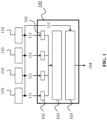
- FIG. 1 shows a device 100 for illustrative purposes.
- the device 100 may comprise processing circuitry (not shown) configured to perform, conduct or initiate the various operations of the device 100 described herein.
- the processing circuitry may comprise hardware and software.
- the hardware may comprise analog circuitry or digital circuitry, or both analog and digital circuitry.
- the digital circuitry may comprise components such as application-specific integrated circuits (ASICs), field-programmable arrays (FPGAs), digital signal processors (DSPs), or multi-purpose processors.
- the processing circuitry comprises one or more processors and a non-transitory memory connected to the one or more processors.
- the non-transitory memory may carry executable program code which, when executed by the one or more processors, causes the device 100 to perform, conduct or initiate the operations or methods described herein.
- the device 100 is configured to obtain a FOA signal 104 from signals 111 of at least four directive microphones 110.
- FIG. 1 exemplarily illustrates a scenario with four directive microphones, which may also be four virtual directive microphones (i.e. the sound may actually be captured by omnidirectional microphones).
- the device 100 may be a small and/or mobile device, or may be included in such a mobile device.
- the mobile device may, for example, be a smartphone, tablet, or camera.
- the device 100 is configured to determine a look direction 101 of each directive microphone 110, e.g. based on the respective microphone signals 111.
- the look direction 101 of a directive microphone 110 may be derived based on an azimuth angle and an elevation angle of that microphone or based on an orientation of at least two omnidirectional microphones (in case of a virtual directive microphone 110).
- the device 100 is further configured to calculate a decoding matrix 102 based on the determined look directions 101 of the microphones 110, wherein the decoding matrix 102 is a matrix that is suitable for decoding a FOA signal into the microphone signals 111 of the microphones 110. That is, the decoding matrix 102 is such that it could be used to generate/recover the microphone signals 111 from a FOA signal.
- the device 100 is further configured to invert the decoding matrix 102 to obtain an encoding matrix 103, and to then encode the signals 111 of the microphones 110 based on the obtained encoding matrix 103 to generate the FOA signal 104.
- the FOA signal 104 may then be output, or may be used to obtain a DOA estimate for the microphone signals 111.
- FIG. 2 shows a device 100 according to an embodiment of the invention, which builds on the device 100 shown in FIG. 1 . Same elements in FIG. 1 and FIG. 2 are labelled with the same reference signs and function likewise.
- the device 100 is further shown to include the multiple directive microphones 110.
- the look direction 101 of a microphone 110 may be based on an azimuth angle and an elevation angle of that microphone 110.
- the decoding matrix 102 may specifically be a B-format decoding matrix (e.g. an M x4 matrix).
- the encoding matrix 103 may be a pseudo-inverse encoding matrix (e.g. a 4x M matrix).
- the encoding of the signals 111 may be performed by matrixing the signals 111 with the encoding matrix 103, in order to obtain the FOA signal 104.
- the FOA signal 104 may comprises four FOA channels ( W , X , Y, Z).
- M first-order microphones 110 which are distributed in the XYZ- space with their coordinates: x 1 y 1 z 1 , x 2 y 2 z 2 , ... x M y M z M
- Their look directions 101 may be defined by their azimuth ( ⁇ ) and elevation ( ⁇ ) angles.
- the look direction 101 may in particular be retrieved by using:
- u is the first-order microphone directional response characteristic, i.e.:
- the decoding matrix ⁇ is then inverted, for example, by using a pseudo-inverse algorithm.
- the pseudo-inverse is the generalized inverse of a matrix. It corresponds to solving the overdetermined linear system of the equations (6). It has 0, 1, or infinitely many solutions.
- the equation (8) is the closest solution when none exists in the norm 2 sense, i.e. minimizing
- the encoding matrix 103 can then be directly used to encode the directive microphone signals 111 ( S 1 , S 2 , ...,S M ) into the FOA signal 104. It is also possible to capture/receive microphone signals 111 over time and obtain multiple successive FOA signals.
- the proposed device 100 can achieve an improved 3D audio recording, and particular the following advantages:
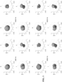
- FIG. 3 shows these directional responses for various octave bands.
- FIG. 5 shows a method 500 according to an embodiment of the invention.
- the method 500 is suitable for obtaining a FOA signal 104 from signals 111 of at least five directive microphones 110.
- the method 500 may be carried out by the device 100 shown in FIG. 2 , or may be carried out by a mobile device including such a device 100.
- the method 500 comprises: a step 501 of determining 501 a look direction 101 of each microphone 110; a step 502 of calculating a decoding matrix 102 based on the determined look directions 101, wherein the decoding matrix 102 is suitable for decoding a FOA signal into the signals 111 of the microphones 110; a step 503 of inverting the decoding matrix 102 to obtain an encoding matrix 103; and a step 503 of encoding 504 the signals 111 of the microphones 110 based on the encoding matrix 103 to obtain the FOA signal 104.
Landscapes
- Engineering & Computer Science (AREA)
- Physics & Mathematics (AREA)
- Acoustics & Sound (AREA)
- Signal Processing (AREA)
- Health & Medical Sciences (AREA)
- Mathematical Physics (AREA)
- Multimedia (AREA)
- Otolaryngology (AREA)
- Human Computer Interaction (AREA)
- Audiology, Speech & Language Pathology (AREA)
- Computational Linguistics (AREA)
- Mathematical Analysis (AREA)
- Algebra (AREA)
- General Physics & Mathematics (AREA)
- General Health & Medical Sciences (AREA)
- Mathematical Optimization (AREA)
- Pure & Applied Mathematics (AREA)
- Theoretical Computer Science (AREA)
- Circuit For Audible Band Transducer (AREA)
- Obtaining Desirable Characteristics In Audible-Bandwidth Transducers (AREA)
- Stereophonic System (AREA)
Description
- The present invention relates to the technical field of audio recording of 3D sound, for instance, for virtual reality (VR) applications or surround sound. The invention thus relates to VR compatible audio formats, i.e. First Order Ambisonic (FOA) signals (also referred to as B-format). The invention proposes a device and method for obtaining a FOA signal. The invention proposes an overdetermined system, in which the device or method obtain the FOA signal from signals of at least five directive microphones.
- VR sound recording typically requires Ambisonics B-format to be captured with four first-order microphone capsules. To this end, professional audio microphones may either record A-format - to be then encoded into B-format by applying a four by four conversion matrix - or may record directly the Ambisonics B-format - for instance by using soundfield, like microphones.
- However, in many consumer products, first-order microphones (or other directive microphones) are not suitable, since they have to lay in free-field to be operational. Instead, omnidirectional microphones are used in such products, and their signals are first mutually pre-processed to obtain at least four virtual first-order microphone signals to be then transformed into FOA.
- In an exemplary method, a pair of two omnidirectional microphone signals can be converted into a first-order differential signal, yielding a virtual cardioid signal. Then, using a distribution of omnidirectional microphones, the resulting four differential signals can be encoded into B-format. However there are two main limitations with this method. A first limitation is related to the spectral defects at higher frequencies (given the spatial aliasing resulting from the microphones spacing), and a second limitation relates to the microphone placement constraints, due to design and hardware specifications, which prevent them looking in all directions.
- The first limitation results from the spatial aliasing, which, by design, reduces the bandwidth to frequencies f in the range of:

- In the above equation (1), c stands for the sound celerity, and dmic stands for the distance between a pair of two omnidirectional microphones.
- Another exemplary method for generating FOA signals from omnidirectional microphones samples the soundfield using a dense enough distribution of microphones (e.g. the Eingenmike with 32 capsules). The sampled sound pressure signals are then converted to spherical harmonics, and then linearly combined to eventually generate FOA signals. The main limitation of this method is the required number of microphones. For consumer applications, with only few microphones available (commonly only up to 6), linear processing is too limited. This limitation leads to signal to noise ratio (SNR) issues at low frequencies, and again, to aliasing at high frequencies.
- In summary, it is a challenging task to provide suitable audio recordings, in particular for VR applications, when using small and/or mobile devices such as phones, tablets, or on-board cameras. The non-consistent dimensions of many mobile devices (large screen/minimum thinness) restrict the possibility to record relevant sound in all directions and over all of the frequency bandwidth. Many constraints result directly from the device design: E.g. often only omnidirectional microphones can be used, while directive microphones are not suitable because they have to lie in free field. Further, microphone placement is often restricted to a limited number of possible positions on the device.
-
US 2018/218740 A1 relates to coding of a soundfield representation. - In view of the above-mentioned challenges and limitations, embodiments of the present invention aim to improve the current methods. The invention is set out in the appended set of claims. An objective is to provide a device and method that enable improved 3D audio recordings, which are suitable for VR applications, and can be performed with small and/or mobile devices. The device and method should provide a FOA signal from multiple microphone signals. The use of directive microphones should be possible. Further, the encoding of the multiple microphone sound signals into the FOA signal should be more robust, in particular over a larger frequency bandwidth and over a larger set of directions.
- The objective is achieved by embodiments of the invention as described in the enclosed independent claims. Advantageous implementations of embodiments are further defined in the dependent claims.
- In particular, considering a system of M≥5 (possibly virtual) directive microphone signals, embodiments of the invention can generate a corresponding FOA signals successively by: deriving the look direction angles of the M directive microphones producing the microphone signals, and then computing a matrix representing how these directive microphones would be obtained for the FOA channels (W, X, Y, Z). This matrix is then inverted, e.g. using a pseudo-inverse algorithm, to obtain an inverted matrix, and the inverted matrix can be applied to the M microphone signals to generate the FOA channels.
- A first aspect of the invention provides a device for obtaining a FOA signal from signals of at least five first-order directive microphones, the device being configured to: determine a look direction of each microphone, calculate a decoding matrix based on the determined look directions, wherein the decoding matrix is suitable for decoding a FOA signal into the signals of the microphones, invert the decoding matrix to obtain an encoding matrix, and encode the signals of the microphones based on the encoding matrix to obtain the FOA signal.
- Thus, the device of the first aspect allows obtaining the FOA signal from multiple microphone signals, wherein the use of directive microphones is possible. The device size can be reduced compared to the exemplary methods described above. Due to the calculation and use of the encoding matrix, the encoding of the multiple microphone sound signals into the FOA signal is also more robust, in particular over a larger frequency bandwidth and over a larger set of directions. Thus, the device of the first aspect enables improved recording of 3D audio suitable for VR applications and/or surround sound.
- In this implementation form, the device of the first aspect and the microphones provide an overdetermined system of M>4 directive microphone signals. This leads to even more accurate directional responses, and thus a more accurate FOA signal.
- In an implementation form of the first aspect, the device comprises the at least five first-order directive microphones.
- Thus, limitations of the exemplary methods mentioned above are overcome, and directive microphones can be used in the device. The device can be reduced in size.
- In an implementation form of the first aspect, at least one of the microphones is a virtual directive microphone, in particular based on at least two omnidirectional microphones.
- In an implementation form of the first aspect, the device is further configured to determine the look direction of the virtual directive microphone based on an orientation of the at least two omnidirectional microphones.
- Thus, an alternative to the used of directive microphones is provided. It is also possible to have directive microphones and omnidirectional microphones, of which the device receives signals, or which are part of the device.
- In an implementation form of the first aspect, the look direction of a microphone is based on an azimuth angle and an elevation angle of that microphone.
- In an implementation form of the first aspect, the decoding matrix is a B-format decoding matrix.
- In an implementation form of the first aspect, the device is further configured to invert the decoding matrix using a pseudo-inverse algorithm.
- In an implementation form of the first aspect, the device is further configured to perform a Direction of Arrival (DOA) estimation based on the FOA signal.
- In an implementation form of the first aspect, the FOA signal comprises four FOA channels.
- In an implementation form of the first aspect, the device is a mobile device.
- For instance, the device may be a mobile phone, smartphone, laptop, tablet, camera, on-board camera or similar device. The device can have a larger screen and/or can be fabricated thinner than a device working with an exemplary method described above.
- A second aspect of the invention provides a mobile device, particularly a smartphone, tablet or camera, including the device according to the first aspect or any of its implementation forms.
- The mobile device enjoys all advantages and technical effects described above for the device of the first aspect.
- A third aspect of the invention provides a method for obtaining a FOA signal from signals of at least five first-order directive microphones, the method comprising: determining a look direction of each microphone, calculating a decoding matrix based on the determined look directions, wherein the decoding matrix is suitable for decoding a FOA signal into the signals of the microphones, inverting the decoding matrix to obtain an encoding matrix, and encoding the signals of the microphones based on the encoding matrix to obtain the FOA signal.
- In an implementation form of the third aspect, the method is performed by or in a mobile device.
- In an implementation form of the third aspect, at least one of the microphones is a virtual directive microphone, in particular based on at least two omnidirectional microphones.
- In an implementation form of the third aspect, the method further comprises: determining the look direction of the virtual directive microphone based on an orientation of the at least two omnidirectional microphones.
- In an implementation form of the third aspect, the look direction of a microphone is based on an azimuth angle and an elevation angle of that microphone.
- In an implementation form of the third aspect, the decoding matrix is a B-format decoding matrix.
- In an implementation form of the third aspect, the method further comprises: inverting the decoding matrix using a pseudo-inverse algorithm.
- In an implementation form of the third aspect, the method further comprises: performing a DOA estimation based on the FOA signal.
- In an implementation form of the third aspect, the FOA signal comprises four FOA channels.
- Accordingly, the method of the third aspect and its implementation forms achieve the same advantages and technical effects as described above for the device of the first aspect and its respective implementation forms, in particular because the method can be performed by the device of the first aspect.
- A fourth aspect of the invention provides a computer program product comprising a program code for controlling a device according to the first aspect or any of its implementation forms, or for carrying out, when implemented on a processor, the method according to the third aspect or any of its implementation forms.
- Thus, all advantages and technical effects described above for the device of the first aspect and method of the third aspect can be achieved.
- It has to be noted that all devices, elements, units and means described in the present application could be implemented in the software or hardware elements or any kind of combination thereof. All steps which are performed by the various entities described in the present application as well as the functionalities described to be performed by the various entities are intended to mean that the respective entity is adapted to or configured to perform the respective steps and functionalities. Even if, in the following description of specific embodiments, a specific functionality or step to be performed by external entities is not reflected in the description of a specific detailed element of that entity which performs that specific step or functionality, it should be clear for a skilled person that these methods and functionalities can be implemented in respective software or hardware elements, or any kind of combination thereof.
- The above described aspects and implementation forms of the present invention will be explained in the following description of specific embodiments in relation to the enclosed drawings, in which
- FIG. 1
- shows a device for obtaining a FOA signal from signals of at least four directive microphones for illustrative purposes.
- FIG. 2
- shows a device for obtaining a FOA signal from signals of at least five directive microphones according to an embodiment of the invention.
- FIG. 3
- shows measured directional responses of a FOA signal provided by a device according to an embodiment of the invention, using 10 microphone pairs
- FIG. 4
- shows measured directional responses of a FOA signal by a device using 4 microphone pairs for illustrative purposes.
- FIG. 5
- shows a method for obtaining a FOA signal from signals of at least five directive microphones according to an embodiment of the invention.
-
FIG. 1 shows adevice 100 for illustrative purposes. Thedevice 100 may comprise processing circuitry (not shown) configured to perform, conduct or initiate the various operations of thedevice 100 described herein. The processing circuitry may comprise hardware and software. The hardware may comprise analog circuitry or digital circuitry, or both analog and digital circuitry. The digital circuitry may comprise components such as application-specific integrated circuits (ASICs), field-programmable arrays (FPGAs), digital signal processors (DSPs), or multi-purpose processors. In one embodiment, the processing circuitry comprises one or more processors and a non-transitory memory connected to the one or more processors. The non-transitory memory may carry executable program code which, when executed by the one or more processors, causes thedevice 100 to perform, conduct or initiate the operations or methods described herein. - The
device 100 is configured to obtain aFOA signal 104 fromsignals 111 of at least fourdirective microphones 110.FIG. 1 exemplarily illustrates a scenario with four directive microphones, which may also be four virtual directive microphones (i.e. the sound may actually be captured by omnidirectional microphones). Thedevice 100 may be a small and/or mobile device, or may be included in such a mobile device. The mobile device may, for example, be a smartphone, tablet, or camera. - The
device 100 is configured to determine alook direction 101 of eachdirective microphone 110, e.g. based on the respective microphone signals 111. Thelook direction 101 of adirective microphone 110 may be derived based on an azimuth angle and an elevation angle of that microphone or based on an orientation of at least two omnidirectional microphones (in case of a virtual directive microphone 110). - The
device 100 is further configured to calculate adecoding matrix 102 based on thedetermined look directions 101 of themicrophones 110, wherein thedecoding matrix 102 is a matrix that is suitable for decoding a FOA signal into the microphone signals 111 of themicrophones 110. That is, thedecoding matrix 102 is such that it could be used to generate/recover the microphone signals 111 from a FOA signal. - The
device 100 is further configured to invert thedecoding matrix 102 to obtain anencoding matrix 103, and to then encode thesignals 111 of themicrophones 110 based on the obtainedencoding matrix 103 to generate theFOA signal 104. TheFOA signal 104 may then be output, or may be used to obtain a DOA estimate for the microphone signals 111. -
FIG. 2 shows adevice 100 according to an embodiment of the invention, which builds on thedevice 100 shown inFIG. 1 . Same elements inFIG. 1 andFIG. 2 are labelled with the same reference signs and function likewise. - The
device 100 shown inFIG. 2 receivessignals 111 from more than four (e.g. M=5, M=6, M=5-10, M>10, or even M>20) directive (potentially virtual) first-order directive microphones 110. InFIG. 2 , thedevice 100 is further shown to include the multipledirective microphones 110. As shown further inFIG. 2 , thelook direction 101 of amicrophone 110 may be based on an azimuth angle and an elevation angle of thatmicrophone 110. Further, thedecoding matrix 102 may specifically be a B-format decoding matrix (e.g. an Mx4 matrix). Theencoding matrix 103 may be a pseudo-inverse encoding matrix (e.g. a 4xM matrix). The encoding of thesignals 111 may be performed by matrixing thesignals 111 with theencoding matrix 103, in order to obtain theFOA signal 104. TheFOA signal 104 may comprises four FOA channels (W, X, Y, Z). - The functions carried out by the
device 100 shown inFIG. 2 are now further explained. Considered are generally M first-order microphones 110, which are distributed in the XYZ-space with their coordinates:
- Their
look directions 101 may be defined by their azimuth (Θ) and elevation (ϕ) angles. Thelook direction 101 may in particular be retrieved by using: - If considering directly the mth directive microphone 110:


- If considering omnidirectional microphones, pairing them, for instance, considering a pair of omnidirectional microphones i and j to derive the mth virtual first-order directive microphone 110:


- Given the
look directions 101 of the (potentially virtual)directive microphones 110, a corresponding M×4 matrix Γ (the decoding matrix 102) may be obtained, wherein the matrix would enable to retrieve the M microphone signals 111 from the FOA channels (W, X, Y, Z) by:
- The matrix may be:

- Thereby, u is the first-order microphone directional response characteristic, i.e.:
- u<1/2 sub-cardioid
- u=1/2 cardioid
- u=1/3 super-cardioid
- u=1/4 hyper-cardioid
- u=0.0 dipole
- The decoding matrix Γ is then inverted, for example, by using a pseudo-inverse algorithm. The resulting 4×M matrix _1 (the encoding matrix 103):

- The pseudo-inverse is the generalized inverse of a matrix. It corresponds to solving the overdetermined linear system of the equations (6). It has 0, 1, or infinitely many solutions. The equation (8) is the closest solution when none exists in the
norm 2 sense, i.e. minimizing |b s |2. It gives the single answer when one solution exists. And when many exist, it is the smallest solution in the sense that |b|2 is smallest. - The
encoding matrix 103 can then be directly used to encode the directive microphone signals 111 (S 1,S 2,...,SM ) into theFOA signal 104. It is also possible to capture/receivemicrophone signals 111 over time and obtain multiple successive FOA signals. - Given the four encoded FOA channels of the
FOA signal 104, a DOA estimation can be performed based on the FOA signal 104 by:

- The proposed
device 100 according to an embodiment of the invention, e.g. as shown inFIG. 1 orFIG. 2 , can achieve an improved 3D audio recording, and particular the following advantages: - In case of an overdetermined system (M>4) it can exploit the variety of directions (and possibly spacing for omnidirectional pairs) of
microphones 110, and thus obtain very accurate results (FOA signal 104). - Its encoding is more robust, and in particular over a larger frequency bandwidth and over a larger set of directions.
- It is fully backwards compatible with existing FOA decoders.
- As shown in
FIG. 3 , the resulting directional responses of the FOA channels (W, X, Y, Z) have been measured using a phone prototype (including/being adevice 100 according to an embodiment of the invention) with 5 omnidirectional microphone capsules. Using these 5 microphones, up to 10 pairs can be formed leading to M=10 virtual cardioid signals composing the A format (S 1,S 2,···,,S 10), and thus yielding an overdetermined system.FIG. 3 shows these directional responses for various octave bands. -
FIG. 4 shows the directional responses using M=4 microphone pairs in adevice 100 for illustrative purposes. The results shown inFIG. 4 are thus not from an overdetermined system. This leads to somewhat less accurate directional responses compared toFIG. 3 . -
FIG. 5 shows amethod 500 according to an embodiment of the invention. Themethod 500 is suitable for obtaining aFOA signal 104 fromsignals 111 of at least fivedirective microphones 110. Themethod 500 may be carried out by thedevice 100 shown inFIG. 2 , or may be carried out by a mobile device including such adevice 100. - The
method 500 comprises: astep 501 of determining 501 alook direction 101 of eachmicrophone 110; astep 502 of calculating adecoding matrix 102 based on thedetermined look directions 101, wherein thedecoding matrix 102 is suitable for decoding a FOA signal into thesignals 111 of themicrophones 110; astep 503 of inverting thedecoding matrix 102 to obtain anencoding matrix 103; and astep 503 of encoding 504 thesignals 111 of themicrophones 110 based on theencoding matrix 103 to obtain theFOA signal 104. - The present invention has been described in conjunction with various embodiments as examples as well as implementations. However, other variations can be understood and effected by those persons skilled in the art and practicing the claimed invention, from the studies of the drawings, this disclosure and the independent claims. In the claims as well as in the description the word "comprising" does not exclude other elements or steps and the indefinite article "a" or "an" does not exclude a plurality. A single element or other unit may fulfill the functions of several entities or items recited in the claims. The mere fact that certain measures are recited in the mutual different dependent claims does not indicate that a combination of these measures cannot be used in an advantageous implementation.
Claims (13)
- A device (100) for obtaining a First Order Ambisonic, FOA, signal (104) from signals (111) of at least five first-order directive microphones (110) comprised by the device, the device (100) being configured to:determine a look direction (101) of each microphone (110),calculate a decoding matrix (102) based on the determined look directions (101), wherein the decoding matrix (102) is suitable for decoding a FOA signal into the signals (111) of the microphones (110),invert the decoding matrix (102) to obtain an encoding matrix (103), andencode the signals (111) of the microphones (110) based on the encoding matrix (103) to obtain the FOA signal (104).
- The device (100) according to claim 1, wherein:
at least one of the microphones (110) is a virtual directive microphone (110), in particular based on at least two omnidirectional microphones. - The device (100) according to claim 2, configured to:
determine the look direction (101) of the virtual directive microphone (110) based on an orientation of the at least two omnidirectional microphones. - The device (100) according to one of the claims 1 to 3, wherein:
the look direction (101) of a microphone (110) is based on an azimuth angle and an elevation angle of that microphone (110). - The device (100) according to one of the claims 1 to 4, wherein:
the decoding matrix (102) is a B-format decoding matrix. - The device (100) according to one of the claims 1 to 5, configured to:
invert the decoding matrix (102) using a pseudo-inverse algorithm. - The device (100) according to one of the claims 1 to 6, configured to:
perform a Direction of Arrival, DOA, estimation based on the FOA signal (104). - The device (100) according to one of the claims 1 to 7, wherein:
the FOA signal (104) comprises four FOA channels. - The device (100) according to one of the claims 1 to 8, wherein:
the device (100) is a mobile device. - A mobile device, particularly a smartphone, tablet or camera, including the device (100) according to one of the claims 1 to 8.
- A method (500) for obtaining a First Order Ambisonic, FOA, signal (104) from signals (111) of at least five first-order directive microphones (110), the method (500) comprising:determining (501) a look direction (101) of each microphone (110),calculating (502) a decoding matrix (102) based on the determined look directions (101), wherein the decoding matrix (102) is suitable for decoding a FOA signal into the signals (111) of the microphones (110),inverting (503) the decoding matrix (102) to obtain an encoding matrix (103), andencoding (504) the signals (111) of the microphones (110) based on the encoding matrix (103) to obtain the FOA signal (104).
- The method (500) according to claim 11, wherein:
the method (500) is performed by a mobile device comprising the at least five first-order directive microphones (110). - Computer program product comprising a program code for controlling a device (100) according to any one of the claims 1 to 10, or for carrying out, when executed on a processor, the method (500) according to claim 11 or 12.
Applications Claiming Priority (1)
| Application Number | Priority Date | Filing Date | Title |
|---|---|---|---|
| PCT/EP2019/059384 WO2020207596A1 (en) | 2019-04-12 | 2019-04-12 | Device and method for obtaining a first order ambisonic signal |
Publications (2)
| Publication Number | Publication Date |
|---|---|
| EP3948859A1 EP3948859A1 (en) | 2022-02-09 |
| EP3948859B1 true EP3948859B1 (en) | 2024-10-16 |
Family
ID=66175424
Family Applications (1)
| Application Number | Title | Priority Date | Filing Date |
|---|---|---|---|
| EP19717482.4A Active EP3948859B1 (en) | 2019-04-12 | 2019-04-12 | Device and method for obtaining a first order ambisonic signal |
Country Status (5)
| Country | Link |
|---|---|
| US (1) | US11838739B2 (en) |
| EP (1) | EP3948859B1 (en) |
| CN (1) | CN113661538B (en) |
| BR (1) | BR112021020484A2 (en) |
| WO (1) | WO2020207596A1 (en) |
Families Citing this family (1)
| Publication number | Priority date | Publication date | Assignee | Title |
|---|---|---|---|---|
| CN118235431A (en) * | 2022-10-19 | 2024-06-21 | 北京小米移动软件有限公司 | Spatial audio acquisition method and device |
Family Cites Families (13)
| Publication number | Priority date | Publication date | Assignee | Title |
|---|---|---|---|---|
| US5832444A (en) | 1996-09-10 | 1998-11-03 | Schmidt; Jon C. | Apparatus for dynamic range compression of an audio signal |
| GB0105975D0 (en) | 2001-03-10 | 2001-04-25 | Central Research Lab Ltd | A method of modifying low frequency components of a digital audio signal |
| US7084801B2 (en) * | 2002-06-05 | 2006-08-01 | Siemens Corporate Research, Inc. | Apparatus and method for estimating the direction of arrival of a source signal using a microphone array |
| ATE545286T1 (en) * | 2005-06-23 | 2012-02-15 | Akg Acoustics Gmbh | SOUND FIELD MICROPHONE |
| US20110091048A1 (en) | 2006-04-27 | 2011-04-21 | National Chiao Tung University | Method for virtual bass synthesis |
| EP2747449B1 (en) * | 2012-12-20 | 2016-03-30 | Harman Becker Automotive Systems GmbH | Sound capture system |
| KR102433192B1 (en) * | 2014-07-02 | 2022-08-18 | 돌비 인터네셔널 에이비 | Method and apparatus for decoding a compressed hoa representation, and method and apparatus for encoding a compressed hoa representation |
| US10206040B2 (en) * | 2015-10-30 | 2019-02-12 | Essential Products, Inc. | Microphone array for generating virtual sound field |
| US10332530B2 (en) * | 2017-01-27 | 2019-06-25 | Google Llc | Coding of a soundfield representation |
| US10477310B2 (en) * | 2017-08-24 | 2019-11-12 | Qualcomm Incorporated | Ambisonic signal generation for microphone arrays |
| GB2566992A (en) * | 2017-09-29 | 2019-04-03 | Nokia Technologies Oy | Recording and rendering spatial audio signals |
| US10595146B2 (en) * | 2017-12-21 | 2020-03-17 | Verizon Patent And Licensing Inc. | Methods and systems for extracting location-diffused ambient sound from a real-world scene |
| EP3753263B1 (en) * | 2018-03-14 | 2022-08-24 | Huawei Technologies Co., Ltd. | Audio encoding device and method |
-
2019
- 2019-04-12 CN CN201980095064.5A patent/CN113661538B/en active Active
- 2019-04-12 EP EP19717482.4A patent/EP3948859B1/en active Active
- 2019-04-12 BR BR112021020484A patent/BR112021020484A2/en unknown
- 2019-04-12 WO PCT/EP2019/059384 patent/WO2020207596A1/en not_active Ceased
-
2021
- 2021-10-06 US US17/495,359 patent/US11838739B2/en active Active
Non-Patent Citations (1)
| Title |
|---|
| "Ambisonics : A Practical 3D Audio Theory for Recording, Studio Production, Sound Reinforcement, and Virtual Reality", vol. 19, 1 January 2019, SPRINGER INTERNATIONAL PUBLISHING, Cham, ISBN: 978-3-030-17207-7, ISSN: 1866-2609, article ZOTTER FRANZ ET AL: "Higher-Order Ambisonic Microphones and the Wave Equation (Linear, Lossless) : A Practical 3D Audio Theory for Recording, Studio Production, Sound Reinforcement, and Virtual Reality", pages: 131 - 152, XP093105299, DOI: 10.1007/978-3-030-17207-7_6 * |
Also Published As
| Publication number | Publication date |
|---|---|
| CN113661538B (en) | 2024-11-15 |
| CN113661538A (en) | 2021-11-16 |
| WO2020207596A1 (en) | 2020-10-15 |
| US11838739B2 (en) | 2023-12-05 |
| BR112021020484A2 (en) | 2022-01-04 |
| US20220030371A1 (en) | 2022-01-27 |
| EP3948859A1 (en) | 2022-02-09 |
Similar Documents
| Publication | Publication Date | Title |
|---|---|---|
| US12185081B2 (en) | Audio rendering with spatial metadata interpolation | |
| US20220174444A1 (en) | Spatial Audio Signal Format Generation From a Microphone Array Using Adaptive Capture | |
| US10873814B2 (en) | Analysis of spatial metadata from multi-microphones having asymmetric geometry in devices | |
| US8638951B2 (en) | Electronic apparatus for generating modified wideband audio signals based on two or more wideband microphone signals | |
| EP3732678B1 (en) | Determination of spatial audio parameter encoding and associated decoding | |
| EP4004914B1 (en) | Quantization of spatial audio direction parameters | |
| WO2013150341A1 (en) | Flexible spatial audio capture apparatus | |
| EP3777235B9 (en) | Spatial audio capture | |
| WO2021130404A1 (en) | The merging of spatial audio parameters | |
| US12022276B2 (en) | Apparatus, method or computer program for processing a sound field representation in a spatial transform domain | |
| CN103329567A (en) | Apparatus and method for deriving a directional information and computer program product | |
| US11632626B2 (en) | Audio encoding device and method | |
| EP3409025A1 (en) | System and apparatus for tracking moving audio sources | |
| EP3523801B1 (en) | Coding of a soundfield representation | |
| US20200143815A1 (en) | Device and method for capturing and processing a three-dimensional acoustic field | |
| US11838739B2 (en) | Device and method for obtaining a first order ambisonic signal | |
| US12262173B2 (en) | Audio processing device and method for acoustic angle of arrival detection using audio signals of a virtual rotating microphone | |
| US10244317B2 (en) | Beamforming array utilizing ring radiator loudspeakers and digital signal processing (DSP) optimization of a beamforming array | |
| US20260012745A1 (en) | Efficient head-related filter generation | |
| Schörkhuber et al. | Localization of multiple acoustic sources with a distributed array of unsynchronized first-order ambisonics microphones | |
| Andráš et al. | Beamforming with small diameter microphone array | |
| US20150332034A1 (en) | Spatial Audio Apparatus | |
| US12412585B2 (en) | Transforming spatial audio parameters | |
| EP3977447B1 (en) | Omni-directional encoding and decoding for ambisonics | |
| James Esplin et al. | The effects of non-cardioid directivity on incidence angle estimation using the polar energy time curve |
Legal Events
| Date | Code | Title | Description |
|---|---|---|---|
| STAA | Information on the status of an ep patent application or granted ep patent |
Free format text: STATUS: UNKNOWN |
|
| STAA | Information on the status of an ep patent application or granted ep patent |
Free format text: STATUS: THE INTERNATIONAL PUBLICATION HAS BEEN MADE |
|
| PUAI | Public reference made under article 153(3) epc to a published international application that has entered the european phase |
Free format text: ORIGINAL CODE: 0009012 |
|
| STAA | Information on the status of an ep patent application or granted ep patent |
Free format text: STATUS: REQUEST FOR EXAMINATION WAS MADE |
|
| 17P | Request for examination filed |
Effective date: 20211025 |
|
| AK | Designated contracting states |
Kind code of ref document: A1 Designated state(s): AL AT BE BG CH CY CZ DE DK EE ES FI FR GB GR HR HU IE IS IT LI LT LU LV MC MK MT NL NO PL PT RO RS SE SI SK SM TR |
|
| DAV | Request for validation of the european patent (deleted) | ||
| DAX | Request for extension of the european patent (deleted) | ||
| GRAP | Despatch of communication of intention to grant a patent |
Free format text: ORIGINAL CODE: EPIDOSNIGR1 |
|
| STAA | Information on the status of an ep patent application or granted ep patent |
Free format text: STATUS: GRANT OF PATENT IS INTENDED |
|
| INTG | Intention to grant announced |
Effective date: 20231208 |
|
| GRAJ | Information related to disapproval of communication of intention to grant by the applicant or resumption of examination proceedings by the epo deleted |
Free format text: ORIGINAL CODE: EPIDOSDIGR1 |
|
| STAA | Information on the status of an ep patent application or granted ep patent |
Free format text: STATUS: REQUEST FOR EXAMINATION WAS MADE |
|
| GRAP | Despatch of communication of intention to grant a patent |
Free format text: ORIGINAL CODE: EPIDOSNIGR1 |
|
| STAA | Information on the status of an ep patent application or granted ep patent |
Free format text: STATUS: GRANT OF PATENT IS INTENDED |
|
| INTC | Intention to grant announced (deleted) | ||
| INTG | Intention to grant announced |
Effective date: 20240508 |
|
| GRAS | Grant fee paid |
Free format text: ORIGINAL CODE: EPIDOSNIGR3 |
|
| GRAA | (expected) grant |
Free format text: ORIGINAL CODE: 0009210 |
|
| STAA | Information on the status of an ep patent application or granted ep patent |
Free format text: STATUS: THE PATENT HAS BEEN GRANTED |
|
| AK | Designated contracting states |
Kind code of ref document: B1 Designated state(s): AL AT BE BG CH CY CZ DE DK EE ES FI FR GB GR HR HU IE IS IT LI LT LU LV MC MK MT NL NO PL PT RO RS SE SI SK SM TR |
|
| REG | Reference to a national code |
Ref country code: GB Ref legal event code: FG4D |
|
| REG | Reference to a national code |
Ref country code: DE Ref legal event code: R096 Ref document number: 602019060446 Country of ref document: DE Ref country code: CH Ref legal event code: EP |
|
| REG | Reference to a national code |
Ref country code: IE Ref legal event code: FG4D |
|
| REG | Reference to a national code |
Ref country code: LT Ref legal event code: MG9D |
|
| REG | Reference to a national code |
Ref country code: NL Ref legal event code: MP Effective date: 20241016 |
|
| REG | Reference to a national code |
Ref country code: AT Ref legal event code: MK05 Ref document number: 1733607 Country of ref document: AT Kind code of ref document: T Effective date: 20241016 |
|
| PG25 | Lapsed in a contracting state [announced via postgrant information from national office to epo] |
Ref country code: NL Free format text: LAPSE BECAUSE OF FAILURE TO SUBMIT A TRANSLATION OF THE DESCRIPTION OR TO PAY THE FEE WITHIN THE PRESCRIBED TIME-LIMIT Effective date: 20241016 |
|
| PG25 | Lapsed in a contracting state [announced via postgrant information from national office to epo] |
Ref country code: NL Free format text: LAPSE BECAUSE OF FAILURE TO SUBMIT A TRANSLATION OF THE DESCRIPTION OR TO PAY THE FEE WITHIN THE PRESCRIBED TIME-LIMIT Effective date: 20241016 |
|
| PG25 | Lapsed in a contracting state [announced via postgrant information from national office to epo] |
Ref country code: PT Free format text: LAPSE BECAUSE OF FAILURE TO SUBMIT A TRANSLATION OF THE DESCRIPTION OR TO PAY THE FEE WITHIN THE PRESCRIBED TIME-LIMIT Effective date: 20250217 Ref country code: IS Free format text: LAPSE BECAUSE OF FAILURE TO SUBMIT A TRANSLATION OF THE DESCRIPTION OR TO PAY THE FEE WITHIN THE PRESCRIBED TIME-LIMIT Effective date: 20250216 Ref country code: HR Free format text: LAPSE BECAUSE OF FAILURE TO SUBMIT A TRANSLATION OF THE DESCRIPTION OR TO PAY THE FEE WITHIN THE PRESCRIBED TIME-LIMIT Effective date: 20241016 |
|
| PG25 | Lapsed in a contracting state [announced via postgrant information from national office to epo] |
Ref country code: FI Free format text: LAPSE BECAUSE OF FAILURE TO SUBMIT A TRANSLATION OF THE DESCRIPTION OR TO PAY THE FEE WITHIN THE PRESCRIBED TIME-LIMIT Effective date: 20241016 |
|
| PG25 | Lapsed in a contracting state [announced via postgrant information from national office to epo] |
Ref country code: BG Free format text: LAPSE BECAUSE OF FAILURE TO SUBMIT A TRANSLATION OF THE DESCRIPTION OR TO PAY THE FEE WITHIN THE PRESCRIBED TIME-LIMIT Effective date: 20241016 |
|
| PG25 | Lapsed in a contracting state [announced via postgrant information from national office to epo] |
Ref country code: ES Free format text: LAPSE BECAUSE OF FAILURE TO SUBMIT A TRANSLATION OF THE DESCRIPTION OR TO PAY THE FEE WITHIN THE PRESCRIBED TIME-LIMIT Effective date: 20241016 |
|
| PG25 | Lapsed in a contracting state [announced via postgrant information from national office to epo] |
Ref country code: NO Free format text: LAPSE BECAUSE OF FAILURE TO SUBMIT A TRANSLATION OF THE DESCRIPTION OR TO PAY THE FEE WITHIN THE PRESCRIBED TIME-LIMIT Effective date: 20250116 |
|
| PG25 | Lapsed in a contracting state [announced via postgrant information from national office to epo] |
Ref country code: AT Free format text: LAPSE BECAUSE OF FAILURE TO SUBMIT A TRANSLATION OF THE DESCRIPTION OR TO PAY THE FEE WITHIN THE PRESCRIBED TIME-LIMIT Effective date: 20241016 Ref country code: LV Free format text: LAPSE BECAUSE OF FAILURE TO SUBMIT A TRANSLATION OF THE DESCRIPTION OR TO PAY THE FEE WITHIN THE PRESCRIBED TIME-LIMIT Effective date: 20241016 Ref country code: GR Free format text: LAPSE BECAUSE OF FAILURE TO SUBMIT A TRANSLATION OF THE DESCRIPTION OR TO PAY THE FEE WITHIN THE PRESCRIBED TIME-LIMIT Effective date: 20250117 |
|
| PG25 | Lapsed in a contracting state [announced via postgrant information from national office to epo] |
Ref country code: PL Free format text: LAPSE BECAUSE OF FAILURE TO SUBMIT A TRANSLATION OF THE DESCRIPTION OR TO PAY THE FEE WITHIN THE PRESCRIBED TIME-LIMIT Effective date: 20241016 |
|
| PG25 | Lapsed in a contracting state [announced via postgrant information from national office to epo] |
Ref country code: RS Free format text: LAPSE BECAUSE OF FAILURE TO SUBMIT A TRANSLATION OF THE DESCRIPTION OR TO PAY THE FEE WITHIN THE PRESCRIBED TIME-LIMIT Effective date: 20250116 |
|
| PG25 | Lapsed in a contracting state [announced via postgrant information from national office to epo] |
Ref country code: SM Free format text: LAPSE BECAUSE OF FAILURE TO SUBMIT A TRANSLATION OF THE DESCRIPTION OR TO PAY THE FEE WITHIN THE PRESCRIBED TIME-LIMIT Effective date: 20241016 |
|
| PG25 | Lapsed in a contracting state [announced via postgrant information from national office to epo] |
Ref country code: DK Free format text: LAPSE BECAUSE OF FAILURE TO SUBMIT A TRANSLATION OF THE DESCRIPTION OR TO PAY THE FEE WITHIN THE PRESCRIBED TIME-LIMIT Effective date: 20241016 |
|
| REG | Reference to a national code |
Ref country code: DE Ref legal event code: R097 Ref document number: 602019060446 Country of ref document: DE |
|
| PG25 | Lapsed in a contracting state [announced via postgrant information from national office to epo] |
Ref country code: EE Free format text: LAPSE BECAUSE OF FAILURE TO SUBMIT A TRANSLATION OF THE DESCRIPTION OR TO PAY THE FEE WITHIN THE PRESCRIBED TIME-LIMIT Effective date: 20241016 |
|
| PG25 | Lapsed in a contracting state [announced via postgrant information from national office to epo] |
Ref country code: RO Free format text: LAPSE BECAUSE OF FAILURE TO SUBMIT A TRANSLATION OF THE DESCRIPTION OR TO PAY THE FEE WITHIN THE PRESCRIBED TIME-LIMIT Effective date: 20241016 |
|
| PG25 | Lapsed in a contracting state [announced via postgrant information from national office to epo] |
Ref country code: SK Free format text: LAPSE BECAUSE OF FAILURE TO SUBMIT A TRANSLATION OF THE DESCRIPTION OR TO PAY THE FEE WITHIN THE PRESCRIBED TIME-LIMIT Effective date: 20241016 |
|
| PG25 | Lapsed in a contracting state [announced via postgrant information from national office to epo] |
Ref country code: CZ Free format text: LAPSE BECAUSE OF FAILURE TO SUBMIT A TRANSLATION OF THE DESCRIPTION OR TO PAY THE FEE WITHIN THE PRESCRIBED TIME-LIMIT Effective date: 20241016 |
|
| PG25 | Lapsed in a contracting state [announced via postgrant information from national office to epo] |
Ref country code: IT Free format text: LAPSE BECAUSE OF FAILURE TO SUBMIT A TRANSLATION OF THE DESCRIPTION OR TO PAY THE FEE WITHIN THE PRESCRIBED TIME-LIMIT Effective date: 20241016 |
|
| PLBE | No opposition filed within time limit |
Free format text: ORIGINAL CODE: 0009261 |
|
| STAA | Information on the status of an ep patent application or granted ep patent |
Free format text: STATUS: NO OPPOSITION FILED WITHIN TIME LIMIT |
|
| PG25 | Lapsed in a contracting state [announced via postgrant information from national office to epo] |
Ref country code: SE Free format text: LAPSE BECAUSE OF FAILURE TO SUBMIT A TRANSLATION OF THE DESCRIPTION OR TO PAY THE FEE WITHIN THE PRESCRIBED TIME-LIMIT Effective date: 20241016 |
|
| 26N | No opposition filed |
Effective date: 20250717 |
|
| REG | Reference to a national code |
Ref country code: CH Ref legal event code: H13 Free format text: ST27 STATUS EVENT CODE: U-0-0-H10-H13 (AS PROVIDED BY THE NATIONAL OFFICE) Effective date: 20251125 |
|
| PG25 | Lapsed in a contracting state [announced via postgrant information from national office to epo] |
Ref country code: LU Free format text: LAPSE BECAUSE OF NON-PAYMENT OF DUE FEES Effective date: 20250412 |
|
| PG25 | Lapsed in a contracting state [announced via postgrant information from national office to epo] |
Ref country code: MC Free format text: LAPSE BECAUSE OF FAILURE TO SUBMIT A TRANSLATION OF THE DESCRIPTION OR TO PAY THE FEE WITHIN THE PRESCRIBED TIME-LIMIT Effective date: 20241016 |
|
| REG | Reference to a national code |
Ref country code: BE Ref legal event code: MM Effective date: 20250430 |
|
| PG25 | Lapsed in a contracting state [announced via postgrant information from national office to epo] |
Ref country code: BE Free format text: LAPSE BECAUSE OF NON-PAYMENT OF DUE FEES Effective date: 20250430 |
|
| PG25 | Lapsed in a contracting state [announced via postgrant information from national office to epo] |
Ref country code: CH Free format text: LAPSE BECAUSE OF NON-PAYMENT OF DUE FEES Effective date: 20250430 |
|
| PGFP | Annual fee paid to national office [announced via postgrant information from national office to epo] |
Ref country code: GB Payment date: 20260310 Year of fee payment: 8 |
|
| PG25 | Lapsed in a contracting state [announced via postgrant information from national office to epo] |
Ref country code: IE Free format text: LAPSE BECAUSE OF NON-PAYMENT OF DUE FEES Effective date: 20250412 |
|
| PGFP | Annual fee paid to national office [announced via postgrant information from national office to epo] |
Ref country code: FR Payment date: 20260309 Year of fee payment: 8 |
|
| PG25 | Lapsed in a contracting state [announced via postgrant information from national office to epo] |
Ref country code: CY Free format text: LAPSE BECAUSE OF FAILURE TO SUBMIT A TRANSLATION OF THE DESCRIPTION OR TO PAY THE FEE WITHIN THE PRESCRIBED TIME-LIMIT Effective date: 20241016 |
|
| PG25 | Lapsed in a contracting state [announced via postgrant information from national office to epo] |
Ref country code: LT Free format text: LAPSE BECAUSE OF FAILURE TO SUBMIT A TRANSLATION OF THE DESCRIPTION OR TO PAY THE FEE WITHIN THE PRESCRIBED TIME-LIMIT Effective date: 20241016 |
|
| PGFP | Annual fee paid to national office [announced via postgrant information from national office to epo] |
Ref country code: DE Payment date: 20260305 Year of fee payment: 8 |