EP3948847B1 - Active sound management in noise cancelation systems - Google Patents
Active sound management in noise cancelation systems Download PDFInfo
- Publication number
- EP3948847B1 EP3948847B1 EP20721056.8A EP20721056A EP3948847B1 EP 3948847 B1 EP3948847 B1 EP 3948847B1 EP 20721056 A EP20721056 A EP 20721056A EP 3948847 B1 EP3948847 B1 EP 3948847B1
- Authority
- EP
- European Patent Office
- Prior art keywords
- signal
- rotational rate
- noise cancellation
- noise
- change
- Prior art date
- Legal status (The legal status is an assumption and is not a legal conclusion. Google has not performed a legal analysis and makes no representation as to the accuracy of the status listed.)
- Active
Links
Images



Classifications
-
- G—PHYSICS
- G10—MUSICAL INSTRUMENTS; ACOUSTICS
- G10K—SOUND-PRODUCING DEVICES; METHODS OR DEVICES FOR PROTECTING AGAINST, OR FOR DAMPING, NOISE OR OTHER ACOUSTIC WAVES IN GENERAL; ACOUSTICS NOT OTHERWISE PROVIDED FOR
- G10K11/00—Methods or devices for transmitting, conducting or directing sound in general; Methods or devices for protecting against, or for damping, noise or other acoustic waves in general
- G10K11/16—Methods or devices for protecting against, or for damping, noise or other acoustic waves in general
- G10K11/175—Methods or devices for protecting against, or for damping, noise or other acoustic waves in general using interference effects; Masking sound
- G10K11/178—Methods or devices for protecting against, or for damping, noise or other acoustic waves in general using interference effects; Masking sound by electro-acoustically regenerating the original acoustic waves in anti-phase
-
- G—PHYSICS
- G10—MUSICAL INSTRUMENTS; ACOUSTICS
- G10K—SOUND-PRODUCING DEVICES; METHODS OR DEVICES FOR PROTECTING AGAINST, OR FOR DAMPING, NOISE OR OTHER ACOUSTIC WAVES IN GENERAL; ACOUSTICS NOT OTHERWISE PROVIDED FOR
- G10K11/00—Methods or devices for transmitting, conducting or directing sound in general; Methods or devices for protecting against, or for damping, noise or other acoustic waves in general
- G10K11/16—Methods or devices for protecting against, or for damping, noise or other acoustic waves in general
- G10K11/175—Methods or devices for protecting against, or for damping, noise or other acoustic waves in general using interference effects; Masking sound
- G10K11/178—Methods or devices for protecting against, or for damping, noise or other acoustic waves in general using interference effects; Masking sound by electro-acoustically regenerating the original acoustic waves in anti-phase
- G10K11/1785—Methods, e.g. algorithms; Devices
- G10K11/17853—Methods, e.g. algorithms; Devices of the filter
- G10K11/17854—Methods, e.g. algorithms; Devices of the filter the filter being an adaptive filter
-
- G—PHYSICS
- G10—MUSICAL INSTRUMENTS; ACOUSTICS
- G10K—SOUND-PRODUCING DEVICES; METHODS OR DEVICES FOR PROTECTING AGAINST, OR FOR DAMPING, NOISE OR OTHER ACOUSTIC WAVES IN GENERAL; ACOUSTICS NOT OTHERWISE PROVIDED FOR
- G10K11/00—Methods or devices for transmitting, conducting or directing sound in general; Methods or devices for protecting against, or for damping, noise or other acoustic waves in general
- G10K11/16—Methods or devices for protecting against, or for damping, noise or other acoustic waves in general
- G10K11/175—Methods or devices for protecting against, or for damping, noise or other acoustic waves in general using interference effects; Masking sound
- G10K11/178—Methods or devices for protecting against, or for damping, noise or other acoustic waves in general using interference effects; Masking sound by electro-acoustically regenerating the original acoustic waves in anti-phase
- G10K11/1781—Methods or devices for protecting against, or for damping, noise or other acoustic waves in general using interference effects; Masking sound by electro-acoustically regenerating the original acoustic waves in anti-phase characterised by the analysis of input or output signals, e.g. frequency range, modes, transfer functions
- G10K11/17821—Methods or devices for protecting against, or for damping, noise or other acoustic waves in general using interference effects; Masking sound by electro-acoustically regenerating the original acoustic waves in anti-phase characterised by the analysis of input or output signals, e.g. frequency range, modes, transfer functions characterised by the analysis of the input signals only
- G10K11/17823—Reference signals, e.g. ambient acoustic environment
-
- G—PHYSICS
- G10—MUSICAL INSTRUMENTS; ACOUSTICS
- G10K—SOUND-PRODUCING DEVICES; METHODS OR DEVICES FOR PROTECTING AGAINST, OR FOR DAMPING, NOISE OR OTHER ACOUSTIC WAVES IN GENERAL; ACOUSTICS NOT OTHERWISE PROVIDED FOR
- G10K11/00—Methods or devices for transmitting, conducting or directing sound in general; Methods or devices for protecting against, or for damping, noise or other acoustic waves in general
- G10K11/16—Methods or devices for protecting against, or for damping, noise or other acoustic waves in general
- G10K11/175—Methods or devices for protecting against, or for damping, noise or other acoustic waves in general using interference effects; Masking sound
- G10K11/178—Methods or devices for protecting against, or for damping, noise or other acoustic waves in general using interference effects; Masking sound by electro-acoustically regenerating the original acoustic waves in anti-phase
- G10K11/1781—Methods or devices for protecting against, or for damping, noise or other acoustic waves in general using interference effects; Masking sound by electro-acoustically regenerating the original acoustic waves in anti-phase characterised by the analysis of input or output signals, e.g. frequency range, modes, transfer functions
- G10K11/17821—Methods or devices for protecting against, or for damping, noise or other acoustic waves in general using interference effects; Masking sound by electro-acoustically regenerating the original acoustic waves in anti-phase characterised by the analysis of input or output signals, e.g. frequency range, modes, transfer functions characterised by the analysis of the input signals only
- G10K11/17825—Error signals
-
- G—PHYSICS
- G10—MUSICAL INSTRUMENTS; ACOUSTICS
- G10K—SOUND-PRODUCING DEVICES; METHODS OR DEVICES FOR PROTECTING AGAINST, OR FOR DAMPING, NOISE OR OTHER ACOUSTIC WAVES IN GENERAL; ACOUSTICS NOT OTHERWISE PROVIDED FOR
- G10K11/00—Methods or devices for transmitting, conducting or directing sound in general; Methods or devices for protecting against, or for damping, noise or other acoustic waves in general
- G10K11/16—Methods or devices for protecting against, or for damping, noise or other acoustic waves in general
- G10K11/175—Methods or devices for protecting against, or for damping, noise or other acoustic waves in general using interference effects; Masking sound
- G10K11/178—Methods or devices for protecting against, or for damping, noise or other acoustic waves in general using interference effects; Masking sound by electro-acoustically regenerating the original acoustic waves in anti-phase
- G10K11/1787—General system configurations
- G10K11/17879—General system configurations using both a reference signal and an error signal
- G10K11/17881—General system configurations using both a reference signal and an error signal the reference signal being an acoustic signal, e.g. recorded with a microphone
-
- G—PHYSICS
- G10—MUSICAL INSTRUMENTS; ACOUSTICS
- G10K—SOUND-PRODUCING DEVICES; METHODS OR DEVICES FOR PROTECTING AGAINST, OR FOR DAMPING, NOISE OR OTHER ACOUSTIC WAVES IN GENERAL; ACOUSTICS NOT OTHERWISE PROVIDED FOR
- G10K11/00—Methods or devices for transmitting, conducting or directing sound in general; Methods or devices for protecting against, or for damping, noise or other acoustic waves in general
- G10K11/16—Methods or devices for protecting against, or for damping, noise or other acoustic waves in general
- G10K11/175—Methods or devices for protecting against, or for damping, noise or other acoustic waves in general using interference effects; Masking sound
- G10K11/178—Methods or devices for protecting against, or for damping, noise or other acoustic waves in general using interference effects; Masking sound by electro-acoustically regenerating the original acoustic waves in anti-phase
- G10K11/1787—General system configurations
- G10K11/17885—General system configurations additionally using a desired external signal, e.g. pass-through audio such as music or speech
-
- B—PERFORMING OPERATIONS; TRANSPORTING
- B60—VEHICLES IN GENERAL
- B60Q—ARRANGEMENT OF SIGNALLING OR LIGHTING DEVICES, THE MOUNTING OR SUPPORTING THEREOF OR CIRCUITS THEREFOR, FOR VEHICLES IN GENERAL
- B60Q9/00—Arrangement or adaptation of signal devices not provided for in one of main groups B60Q1/00 - B60Q7/00, e.g. haptic signalling
-
- G—PHYSICS
- G10—MUSICAL INSTRUMENTS; ACOUSTICS
- G10K—SOUND-PRODUCING DEVICES; METHODS OR DEVICES FOR PROTECTING AGAINST, OR FOR DAMPING, NOISE OR OTHER ACOUSTIC WAVES IN GENERAL; ACOUSTICS NOT OTHERWISE PROVIDED FOR
- G10K2210/00—Details of active noise control [ANC] covered by G10K11/178 but not provided for in any of its subgroups
- G10K2210/10—Applications
- G10K2210/121—Rotating machines, e.g. engines, turbines, motors; Periodic or quasi-periodic signals in general
-
- G—PHYSICS
- G10—MUSICAL INSTRUMENTS; ACOUSTICS
- G10K—SOUND-PRODUCING DEVICES; METHODS OR DEVICES FOR PROTECTING AGAINST, OR FOR DAMPING, NOISE OR OTHER ACOUSTIC WAVES IN GENERAL; ACOUSTICS NOT OTHERWISE PROVIDED FOR
- G10K2210/00—Details of active noise control [ANC] covered by G10K11/178 but not provided for in any of its subgroups
- G10K2210/10—Applications
- G10K2210/128—Vehicles
- G10K2210/1282—Automobiles
-
- G—PHYSICS
- G10—MUSICAL INSTRUMENTS; ACOUSTICS
- G10K—SOUND-PRODUCING DEVICES; METHODS OR DEVICES FOR PROTECTING AGAINST, OR FOR DAMPING, NOISE OR OTHER ACOUSTIC WAVES IN GENERAL; ACOUSTICS NOT OTHERWISE PROVIDED FOR
- G10K2210/00—Details of active noise control [ANC] covered by G10K11/178 but not provided for in any of its subgroups
- G10K2210/10—Applications
- G10K2210/128—Vehicles
- G10K2210/1282—Automobiles
- G10K2210/12821—Rolling noise; Wind and body noise
-
- G—PHYSICS
- G10—MUSICAL INSTRUMENTS; ACOUSTICS
- G10K—SOUND-PRODUCING DEVICES; METHODS OR DEVICES FOR PROTECTING AGAINST, OR FOR DAMPING, NOISE OR OTHER ACOUSTIC WAVES IN GENERAL; ACOUSTICS NOT OTHERWISE PROVIDED FOR
- G10K2210/00—Details of active noise control [ANC] covered by G10K11/178 but not provided for in any of its subgroups
- G10K2210/30—Means
- G10K2210/301—Computational
- G10K2210/3011—Single acoustic input
-
- G—PHYSICS
- G10—MUSICAL INSTRUMENTS; ACOUSTICS
- G10K—SOUND-PRODUCING DEVICES; METHODS OR DEVICES FOR PROTECTING AGAINST, OR FOR DAMPING, NOISE OR OTHER ACOUSTIC WAVES IN GENERAL; ACOUSTICS NOT OTHERWISE PROVIDED FOR
- G10K2210/00—Details of active noise control [ANC] covered by G10K11/178 but not provided for in any of its subgroups
- G10K2210/30—Means
- G10K2210/301—Computational
- G10K2210/3014—Adaptive noise equalizers [ANE], i.e. where part of the unwanted sound is retained
-
- G—PHYSICS
- G10—MUSICAL INSTRUMENTS; ACOUSTICS
- G10K—SOUND-PRODUCING DEVICES; METHODS OR DEVICES FOR PROTECTING AGAINST, OR FOR DAMPING, NOISE OR OTHER ACOUSTIC WAVES IN GENERAL; ACOUSTICS NOT OTHERWISE PROVIDED FOR
- G10K2210/00—Details of active noise control [ANC] covered by G10K11/178 but not provided for in any of its subgroups
- G10K2210/30—Means
- G10K2210/301—Computational
- G10K2210/3026—Feedback
-
- G—PHYSICS
- G10—MUSICAL INSTRUMENTS; ACOUSTICS
- G10K—SOUND-PRODUCING DEVICES; METHODS OR DEVICES FOR PROTECTING AGAINST, OR FOR DAMPING, NOISE OR OTHER ACOUSTIC WAVES IN GENERAL; ACOUSTICS NOT OTHERWISE PROVIDED FOR
- G10K2210/00—Details of active noise control [ANC] covered by G10K11/178 but not provided for in any of its subgroups
- G10K2210/30—Means
- G10K2210/301—Computational
- G10K2210/3027—Feedforward
-
- G—PHYSICS
- G10—MUSICAL INSTRUMENTS; ACOUSTICS
- G10K—SOUND-PRODUCING DEVICES; METHODS OR DEVICES FOR PROTECTING AGAINST, OR FOR DAMPING, NOISE OR OTHER ACOUSTIC WAVES IN GENERAL; ACOUSTICS NOT OTHERWISE PROVIDED FOR
- G10K2210/00—Details of active noise control [ANC] covered by G10K11/178 but not provided for in any of its subgroups
- G10K2210/30—Means
- G10K2210/301—Computational
- G10K2210/3028—Filtering, e.g. Kalman filters or special analogue or digital filters
Definitions
- Example road noise cancellation (RNC) systems may generate audio signals intended to counter road noise, and may use accelerometers in various locations in a vehicle to provide a road noise reference source. Feedback microphones may monitor the resulting acoustic energy in the vehicle cabin and adjust various operational characteristics of the road noise cancellation system, such as adaptive feedforward filters and the like. Additionally, active sound management (ASM) systems may operate to enhance or otherwise alter a perceived sound of the vehicle's operation, such as by engine harmonic cancellation (EHC) and/or engine harmonic enhancement (EHE) (collectively, EHx). In various examples, signals generated by the ASM system or the RNC system may interact, such as either system may cause the other to alter operation.
- EHC engine harmonic cancellation
- EHE engine harmonic enhancement
- active sounds generated by the ASM system may be perceived as road noise by the RNC system, such that the RNC system may attempt to reduce the sounds that the ASM system is actively operating to generate.
- Such affect may be further aggravated if engine vibration is picked up by the RNC system's accelerometers. Accordingly, there is a need to resolve or reduce the interaction of ASM and RNC systems.
- Systems and methods disclosed herein are directed to noise cancellation systems, methods, and applications that remove selected signal components, such as those related to the rotation of an engine, from various signals operated upon by the noise cancellation system, to allow the noise cancellation system to operate without interfering in the acoustic sound related to the engine.
- a noise cancellation method includes receiving a reference signal representative of a noise to be reduced, providing a noise cancellation signal based upon the reference signal, receiving a feedback signal representative of a residual noise in the environment, combining the noise cancellation signal with an active sound signal related to engine harmonic of the vehicle, and filtering at least one of the reference signal, the noise cancellation signal, or the feedback signal based upon a rotational rate of a rotating equipment associated with the environment, wherein filtering at least one of the reference signal, the noise cancellation signal, or the feedback signal based upon a rotational rate of a rotating equipment includes filtering out a bandwidth of frequencies based upon a change or a rate of change of the rotational rate.
- Some examples include determining a first rotational rate at a first time, determining a second rotational rate at a second time, and determining a difference between the first rotational rate and the second rotational rate as the change of the rotational rate.
- a range of the bandwidth of frequencies is linearly related to a range of the change of the rotational rate.
- filtering at least one of the reference signal, the noise cancellation signal, or the feedback signal based upon a rotational rate of a rotating equipment includes filtering out a notch of frequencies centered on a frequency based upon the rotational rate.
- the frequency may be a harmonic of the rotational rate in certain examples.
- an audio system comprising a noise cancellation system and an active sound management system
- the noise cancellation system comprising a noise sensor configured to provide a reference signal representative of a noise to be reduced in an environment, a controller coupled to the noise sensor to receive the reference signal and to provide a noise cancellation signal based upon the reference signal, a transducer coupled to the controller to transduce the noise cancellation signal into an acoustic signal in the environment, and a filter coupled to the controller, the filter filtering a selected signal, wherein the selected signal comprises at least one of the reference signal and the noise cancellation signal, based upon a rotational rate of a rotating equipment associated with the environment.
- the active sound management system provides an active sound signal to the transducer, wherein the active sound signal relates to engine harmonic of the vehicle, and wherein filtering the selected signal based upon a rotational rate of a rotating equipment includes filtering out a bandwidth of frequencies based upon a change or a rate of change of the rotational rate.
- Some examples include a feedback sensor to provide a feedback signal representative of a residual noise in the environment, and the selected signal further includes the feedback signal.
- filtering a selected signal based upon a rotational rate of a rotating equipment includes filtering out a bandwidth of frequencies based upon a change of the rotational rate.
- the controller determines a first rotational rate at a first time, determines a second rotational rate at a second time, and determines a difference between the first rotational rate and the second rotational rate as the change of the rotational rate.
- a range of the bandwidth of frequencies is linearly related to a range of the change of the rotational rate.
- filtering a selected signal based upon a rotational rate of a rotating equipment includes filtering out a notch of frequencies centered on a frequency based upon the rotational rate.
- a non-transitory computer readable medium including instructions stored thereon that, when executed by a suitable processor, cause the processor to perform a method according to the first aspect.
- the processor may determine a first rotational rate at a first time, determine a second rotational rate at a second time, and determine a difference between the first rotational rate and the second rotational rate as the change of the rotational rate.
- a range of the bandwidth of frequencies is linearly related to a range of the change of the rotational rate.
- filtering a selected signal based upon a rotational rate of a rotating equipment includes filtering out a notch of frequencies centered on a frequency based upon the rotational rate.
- Noise cancellation systems attempt to acoustically reduce (or 'cancel') various sound in an acoustic space.
- a road noise cancellation (RNC) system may attempt to reduce or "go after" road noise in a cabin of the vehicle.
- Active sound management (ASM) systems such as engine harmonic cancellation (EHC) and engine harmonic enhancement (EHE) systems, attempt to adjust the sound of an engine (or other rotational equipment) related to the operation of the vehicle.
- ASM Active sound management
- EHC engine harmonic cancellation
- EHE engine harmonic enhancement
- aspects of the present disclosure are directed to systems and methods suitable for use in a vehicle to remove or reduce selected signal components of the noise cancellation system, such as signal components related to the engine or other rotational equipment, so that the noise cancellation system will not go after or attempt to reduce the selected signal components.
- an RNC system may alter or reduce the engine sound in the cabin, which may be undesirable.
- the RNC system may attempt to cancel the engine harmonics that the EHE system is generating, especially if a reference signal from accelerometers contains these harmonics.
- an RNC system and an EHC system operate in parallel, there may be adverse effects on stability as both adaptive systems attempt at cancel various engine harmonics.
- filter e.g., remove
- engine harmonics to be removed may be identified by RPM information and/or from the EHx system(s).
- a filter may be applied directly to one or more reference signals, one or more speaker signals (also termed speaker commands or command signals), one or more error or feedback signals, e.g., from a feedback microphone, or any combination of these.
- references to "of” may be construed as inclusive so that any terms described using “or” may indicate any of a single, more than one, and all of the described terms. Any references to front and back, left and right, top and bottom, upper and lower, and vertical and horizontal are intended for convenience of description, not to limit the present systems and methods or their components to any one positional or spatial orientation.
- FIG. 1 is a schematic view of an example noise cancellation system 100 which may perform a norm calculation.
- Noise cancellation system 100 may be configured to destructively interfere with undesired sound in at least one cancellation zone 102 within a predefined volume 104 such as a vehicle cabin.
- a predefined volume 104 such as a vehicle cabin.
- an embodiment of noise cancellation system 100 includes a reference sensor 106, a feedback sensor 108, an transducer 110, and a controller 112.
- reference sensor 106 is configured to generate reference signal(s) 114 representative of the undesired sound, or a source of the undesired sound, within predefined volume 104.
- reference sensor 106 may be an accelerometer mounted to and configured to detect vibrations transmitted through a vehicle structure 116. Vibrations transmitted through the vehicle structure 116 are transduced by the structure into undesired sound in the vehicle cabin (perceived as road noise), thus an accelerometer mounted to the structure provides a signal representative of the undesired sound.
- the noise cancellation system 100 of FIG. 1 illustrates merely an example having a single reference sensor 106, various examples may include multiple reference sensors 106.
- Transducer 110 may be, for example, speakers distributed in discrete locations about the perimeter of the predefined volume.
- four or more speakers may be disposed within a vehicle cabin, each of the four speakers being located within a respective door of the vehicle and configured to project sound into the vehicle cabin.
- speakers may be located within a headrest, or elsewhere in the vehicle cabin.
- a noise cancellation signal 118 is generated by controller 112 and provided to one or more speakers in the predefined volume, which transduce the noise cancellation signal 118 to acoustic energy (i.e., sound waves).
- the acoustic energy produced as a result of noise cancellation signal 118 is approximately 180° out of phase with-and thus destructively interferes with-the undesired sound within the cancellation zone 102.
- the combination of sound waves generated from the noise cancellation signal 118 and the undesired noise in the predefined volume results in cancellation of the undesired noise, as perceived by a listener in a cancellation zone.
- Feedback sensor 108 disposed within the predefined volume, generates a feedback signal 120 based on detection of residual noise resulting from the combination of the sound waves generated from the noise cancellation signal 118 and the undesired sound in the cancellation zone.
- the feedback signal 120 is provided to controller 112 as feedback, feedback signal 120 representing residual noise uncancelled by the noise cancellation signal as well as other acoustic energy.
- Error sensors 108 may be, for example, at least one microphone mounted within a vehicle cabin (e.g., in the roof headrests, pillars, or elsewhere within the cabin).
- the cancellation zone(s) may be positioned remotely from feedback sensor 108.
- the feedback signal 120 may be transformed to represent an estimate of the residual noise in the cancellation zone(s).
- controller 112 may comprise a non-transitory storage medium 122 and processor 124.
- non-transitory storage medium 122 stores program code that, when executed by processor 124, implements the various filters and algorithms described below.
- Controller 112 may be implemented in hardware and/or software.
- the controller may be implemented by a SHARC floating-point DSP processor, but it should be understood that the controller may be implemented by any other processor, FPGA, ASIC, or other suitable hardware.
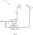
- FIG. 2 there is shown a block diagram of an embodiment of noise cancellation system 100, including filter components implemented by controller 112.
- the controller 112 may define a control system including an adaptive filter 126 and an adaptive processing module 128.
- Adaptive filter 126 is configured to receive the reference signal 114 of reference sensor 106 and to generate noise cancellation signal 118.
- Noise cancellation signal 118 is input to transducer 110 where it is transduced into the noise cancellation audio signal that destructively interferes with the undesired sound in the predefined cancellation zone 102.
- Adaptive filter 126 may be implemented as any suitable linear filter, such as a multi-input multi-output (MIMO) finite impulse response (FIR) filter.
- MIMO multi-input multi-output
- FIR finite impulse response
- Adaptive filter 126 employs a set of coefficients which define the noise cancellation signal 118 in response to the reference signal 114 and which may be adjusted to adapt to changing behavior of the vehicle response to road input (or to other inputs in non-vehicular noise cancellation contexts).
- Adjustments to the coefficients of the adaptive filter 126 may be performed by an adaptive processing module 128, which receives as inputs the feedback signal 120 and the reference signal 114 and, using those inputs, generates a filter update signal 130.
- the filter update signal 130 is an update to the filter coefficients implemented in the adaptive filter 126.
- the noise cancellation signal 118 produced by the updated adaptive filter 126 will minimize feedback signal 120 (or a projection or transform thereof), and consequently reduce the undesired noise in the cancellation zone.
- FIG. 3 illustrates an example audio system 300 that includes a noise cancellation system 100, e.g., as a subsystem, and also includes an active sound management system 310 to provide additional audio signals that may be transduced by the transducer(s) 110.
- Various examples may include additional audio sources, such as entertainment, navigation, and driver warning systems that provide audio signals to also be transduced by the transducer(s) 110.
- the active sound management system 310 provides one or more active sound signal(s) 314 to be rendered by the acoustic transducers 110.
- Examples of the active sound management system 310 may include various acoustic reduction or enhancement systems, such as engine and/or transmission harmonic cancellation and/or enhancement. Such systems may generate sound to enhance or reduce the interior acoustic signature of an engine and power train, a continuously variable transmission, an electric vehicle, or the like, and/or to mimic or mask various acoustic properties to create differing acoustic experiences related to the operation of the vehicle.
- reduced or enhanced sounds may be related to engine or drive train harmonics, and such systems may generally be referred to as engine harmonic cancelation (EHC) and/or engine harmonic enhancement (EHE) systems. Such may also refer to systems that enhance or reduce vehicle sounds not related to harmonics, or that create new sounds, such as a sound generator to create sound effects such as backfire, afterfire, crackle sound effects, and the like.
- an active sound management system 310 may create an acoustic environment intended to make one thing sound like another, such as to make an electric vehicle sound like a gasoline vehicle, or to make a continuously variable transmission sound like gear shifting, or the like, or to make an entirely new machinery sound, for instance.
- the active sound management system may receive any number of input signals 312.
- Example input signals 312 for EHE/EHC systems may include an indication of rotations per minute (RPM), torque, load, temperature, or the like of any of the vehicle rotating equipment (such as engine, transmission, wheels, etc.), or other operating condition of any of the vehicle equipment that may be the basis for producing enhancement or cancellation sounds (e.g., position of an accelerator pedal or control, position of a brake pedal or control, steering wheel position, gear and/or gear changes, or other operator control inputs).
- RPM rotations per minute
- torque load
- temperature or the like of any of the vehicle rotating equipment
- enhancement or cancellation sounds e.g., position of an accelerator pedal or control, position of a brake pedal or control, steering wheel position, gear and/or gear changes, or other operator control inputs.
- an active sound signal 314 is combined with the noise cancellation signal 118 to be transduced by the transducer 110, or the active sound signal 314 and the noise cancellation signal 118 are transduced by separate transducers 110.
- the feedback sensor 108 detects acoustic energy in the environment that may be contributed by each of the noise cancellation signal 118 and the active sound signal 314.
- components of the active sound signals 314 are related to an engine harmonic and optionally harmonics of other portions of rotating equipment of the vehicle, such as a drivetrain and/or wheel(s).
- the reference sensor 106 may detect vibrations related to these harmonics, causing components in the reference signal 114 to also be related to these harmonics.
- the noise cancellation system 100 may go after these harmonic components attempting to reduce their presence in the vehicle cabin while the active sound management system 310 may be attempting to increase these harmonic components in the vehicle cabin.
- these two systems may at best be working against each other.
- Each of the noise cancellation and active sound management systems may also include adaptive operations, thus these two systems may at worst cause instabilities in each other.
- FIG. 4 illustrates an example audio system 400 including example variations from that of the audio system 300 to resolve action by the noise cancellation system 100 that may alter the sound of the engine or other rotating equipment of the vehicle, depending upon the implementation. Accordingly, the example audio system 400 of FIG. 4 may also resolve interaction between the noise cancellation system 100 and the active sound management system 310.
- one or more notch filters configured based upon an RPM 450 operates on at least one of the feedback signal 120, the reference signal 114, the noise cancellation signal 118, or a combination of these signals.
- a filter 410 may be included to modify the feedback signal 120 to remove harmonic components related to the RPM 450.
- a filter 420 may be included to modify the reference signal 114 to remove harmonic components related to the RPM 450.
- a filter 430 may be included to modify the noise cancellation signal 118 to remove harmonic components related to the RPM 450. Any one or more of the filters 410, 420, 430, may reduce the effect of the noise cancellation system 100 on the removed harmonic components related to the RPM 450.
- the filter 410 removes harmonic components from the feedback signal 120, effectively causing the noise cancellation system 100 to think that it has been successful at removing the harmonic components when it hasn't.
- the filter 420 removes harmonic components from the reference signal 114, effectively causing the noise cancellation system 100 to think that the harmonic components aren't a source of noise to be acted upon.
- the filter 430 removes harmonic components from the noise cancellation signal 118, effectively blocking the noise cancellation system 100 from impacting the harmonic components in the vehicle cabin.
- Each of the various filter locations has the potential to degrade performance of the noise cancellation system 100 or to cause instability.
- filtering the reference signal 114 may promote the noise cancellation system 100 to boost adaptive filter values at the frequency of the harmonics.
- Filtering the noise cancellation signal 118 may cause instability in the system as it alters the secondary path.
- the harmonic filter(s) 410, 420, 430 are designed to be as narrow as possible to achieve the desired component removal.
- a challenge in such filtering occurs when the RPM is changing rapidly (e.g. a prompted driving scenario), during which the engine harmonics may deviate from their narrowband nature, and therefore may not be contained with a narrow notch filter. If this deviation is unaccounted, the noise cancellation system may alter the engine sound, which may be particularly undesirable at, e.g., the exact moment when enhanced engine sound is desired, such as during rapid acceleration when the RPM is changing quickly.
- notch filters adjust one or more notch filters at one or more signal path locations in a noise cancellation system.
- the notch filter frequency and bandwidth is based on vehicle operational parameters such as RPM, RPM variation, and torque.
- the filter(s) for example, can be a simple IIR filter, whose poles and zeros are selected by the engine harmonic frequency and rate of RPM change.
- the filtered reduction of harmonic components does not need to be very deep. For example, a 10 dB reduction or less may be sufficient, as the weakened harmonic that is played back in the cabin by RNC may be masked by the actual engine sound and/or an active sound management system.
- a notch filter 430 operates on the noise cancellation signal 118, the notch can be made narrow enough such that no stability issues may be observed, e.g., the notch filter 430 may be designed to remove a narrow enough portion of spectrum that the noise cancellation system is unable to adapt to such a level of frequency resolution / granularity.
- the secondary path is known, and a projection of the signal that was filtered out may be added to the feedback signal such as to prevent the RNC system from boosting the gain at these frequencies.
- multiple notch filters may be cascaded to remove multiple harmonics.
- FIG. 5 illustrates a transfer function 500 of an example notch filter, e.g., which may be any of the filters 410, 420, 430.
- the notch filter removes (attenuates) a narrow range of frequencies centered on a center frequency, f c , and having a notch bandwidth 510 extending from a low frequency, f i , to a high frequency, f h , which in the example notch filter is defined by a 3 dB drop-off from a nominal 0 gain at frequencies outside this range.
- the notch bandwidth may be defined by other amounts of reduction and/or may not have symmetrical response on either side of a center frequency.
- the center frequency is linked to RPM and the notch bandwidth 510 is proportionally linked to the rate of RPM variation.
- RPM varies rapidly, engine harmonics occupy a wider bandwidth, and in many cases may be louder. Widening the notch bandwidth when RPM is changing assists in proper mitigation of the harmonic in these occasions.
- varying notch bandwidth gives flexibility in preserving the most information in the RNC signals when the RPM is not substantially changing. For example, a narrower notch removes less signal content when cruising at an essentially constant RPM, and in such cases road noise may be the dominant noise source and the noise cancellation system 100 is allowed to pursue as much of the noise spectrum as possible.
- a narrow notch bandwidth 510 prevents the adaptive filter 126 from adapting to the filtered harmonic levels, e.g., by having a notch filter bandwidth 510 more narrow than a frequency resolution of the adaptive filter 126.
- the notch filter may be made orders of magnitude narrower than the resolution of the adaptive filter 126, in various examples.
- a broader notch bandwidth 510 accommodates the changing harmonics.
- a filter transfer function 500 for higher order harmonics may have a broader (wider) notch bandwidth 510 than for lower order harmonics.
- a 5 th harmonic may exhibit a wider bandwidth than a 2 nd harmonic, and a filter transfer function 500 intended to attenuate the 5 th harmonic may have a wider notch bandwidth 510 than that intended to attenuate the 2 nd harmonic.
- the center frequency of the notch filter is adjusted to the RPM, and is thus changing in such a scenario. Accordingly, the adaptive filter 126 does not have time to adapt to any particular operation of the notch filter, e.g., the filter(s) 410, 420, and/or 430.
- any of the filter(s) 410, 420, and/or 430 may alter the phase of the signal upon which it operates. Accordingly, the transfer function 500 is relatively narrow in various examples such that the notch filter introduces only a narrow range of phase inaccuracy.
- FIG. 6 illustrates an example digital filter design 600 that may be used in various examples.
- the filter design 600 represents a 2 nd order filter having zeros at the center frequency, which is based upon rotational rate, e.g., RPM, and poles offset from the zeros based upon an amount of change or a rate of change of the rotational rate.
- the offset between a respective pole and zero may be expressed in accord with Eq. 2, ⁇ ⁇ 2 ⁇ BW / 2 f s wherein the bandwidth BW is the notch bandwidth as described above, expressed in the same units as the sampling frequency, f s , such as Hertz.
- Various examples select a bandwidth, BW, based upon a measure of how quickly the RPM is changing, at least one example of which is described in more detail below with respect to FIG. 7 .
- the filter design 600 illustrated in FIG. 6 shows poles substantially in a linear position between a respective zero and the origin, actual implementations may only be approximately placed as illustrated.
- the filter design 600 is merely one example of a filter design that may effectively attenuate a narrow range of frequencies.
- FIG. 7 illustrates one example of a correlation or mapping 700 of a selected notch bandwidth (y-axis) for a given ⁇ RPM (x-axis).
- a selected notch bandwidth is linearly related to the ⁇ RPM, but bound between a minimum and a maximum bandwidth.
- ⁇ RPM may be understood to be a rate of change of RPM, e.g., with respect to time, because while ⁇ RPM is a difference in RPM at two different times, the time difference ⁇ T may be held constant in various examples.
- a value for ⁇ RPM may be determined every 100 milliseconds as a difference between a current RPM and an RPM value from 100 milliseconds earlier.
- a value for ⁇ RPM may be determined every 10 milliseconds as a difference between a current RPM and an RPM value from 10 milliseconds earlier. In various examples, a value for ⁇ RPM may be determined in a range of every 10 to 100 milliseconds.
- Some filtering of an RPM signal or a ⁇ RPM signal may be applied to improve its precision or smoothness. Examples include smoothening (for noise reduction), prediction (to compensate the vehicle's delay in reporting RPM), interpolation (to reduce noise), extrapolation (to add prediction), or any other processing to enhance the accuracy of ⁇ RPM.
- ⁇ RPM can be calculated directly from an analogue signal source such as signals that contain a certain number of pulses per engine rotation.
- Rotations per minute is a conventional unit of measure of a rotational rate, and in various examples a rotational rate may be measured based upon RPM, or based upon timescales other than a minute, and/or based upon other units.
- a change in rotational rate may be positive (increasing) or negative (decreasing).
- an absolute value of the change in rotational rate (or rate of change in rotational rate) may be taken as the basis for selecting a notch bandwidth 510.
- a notch bandwidth 510 for a given filter transfer function 500 may depend upon the harmonic which the notch filter is intended to target. Accordingly, various examples of mapping ⁇ RPM to a notch bandwidth 510 may vary based upon the harmonic to which it is directed. Additionally, a frequency bandwidth of any given harmonic may depend upon the center frequency of the harmonic, e.g., a 80 Hz 1 st harmonic may have a different width than a 80 Hz 2 nd harmonic, and a notch bandwidth 510 may be selected accordingly.
- any of the filters 410, 420, 430 may be filters that attenuate or remove multiple notches, e.g., each having its own center frequency and notch bandwidth.
- notch filter frequencies and notch bandwidths may be more directly controlled by an active sound management system, such as the active sound management system 310.
- the active sound management system may determine what notches and bandwidths are best suited to reduce interaction of the noise cancellation system with the sounds that the active sound management system is managing.
- the active sound management system may or may not base these upon a rotational rate.
- noise cancellation systems and methods herein may be applied to any rotating equipment, such as a motor of an electric vehicle, a drivetrain, a transmission, transaxle, wheels, etc.
- noise cancellation systems and methods disclosed herein may be applied to any environment in which a rotational equipment may generate noise which may be desirable to reduce, such as industrial environments, mass transportation equipment, etc.
Landscapes
- Physics & Mathematics (AREA)
- Engineering & Computer Science (AREA)
- Acoustics & Sound (AREA)
- Multimedia (AREA)
- Health & Medical Sciences (AREA)
- Audiology, Speech & Language Pathology (AREA)
- General Health & Medical Sciences (AREA)
- Soundproofing, Sound Blocking, And Sound Damping (AREA)
- Fittings On The Vehicle Exterior For Carrying Loads, And Devices For Holding Or Mounting Articles (AREA)
- Noise Elimination (AREA)
Description
- This application is related to and claims the benefit of
U.S. Provisional Patent Application Serial Number 62/827,554, titled "ACTIVE SOUND MANAGEMENT IN NOISE CANCELATION SYSTEMS" filed April 1, 2019 - Example road noise cancellation (RNC) systems may generate audio signals intended to counter road noise, and may use accelerometers in various locations in a vehicle to provide a road noise reference source. Feedback microphones may monitor the resulting acoustic energy in the vehicle cabin and adjust various operational characteristics of the road noise cancellation system, such as adaptive feedforward filters and the like. Additionally, active sound management (ASM) systems may operate to enhance or otherwise alter a perceived sound of the vehicle's operation, such as by engine harmonic cancellation (EHC) and/or engine harmonic enhancement (EHE) (collectively, EHx). In various examples, signals generated by the ASM system or the RNC system may interact, such as either system may cause the other to alter operation. For example, active sounds generated by the ASM system may be perceived as road noise by the RNC system, such that the RNC system may attempt to reduce the sounds that the ASM system is actively operating to generate. Such affect may be further aggravated if engine vibration is picked up by the RNC system's accelerometers. Accordingly, there is a need to resolve or reduce the interaction of ASM and RNC systems.
- Documents
US 2006/0269078 andUS 2009/0220102 disclose prior art noise cancelling systems. - Systems and methods disclosed herein are directed to noise cancellation systems, methods, and applications that remove selected signal components, such as those related to the rotation of an engine, from various signals operated upon by the noise cancellation system, to allow the noise cancellation system to operate without interfering in the acoustic sound related to the engine.
- According to one aspect, a noise cancellation method is provided that includes receiving a reference signal representative of a noise to be reduced, providing a noise cancellation signal based upon the reference signal, receiving a feedback signal representative of a residual noise in the environment, combining the noise cancellation signal with an active sound signal related to engine harmonic of the vehicle, and filtering at least one of the reference signal, the noise cancellation signal, or the feedback signal based upon a rotational rate of a rotating equipment associated with the environment, wherein filtering at least one of the reference signal, the noise cancellation signal, or the feedback signal based upon a rotational rate of a rotating equipment includes filtering out a bandwidth of frequencies based upon a change or a rate of change of the rotational rate.
- Some examples include determining a first rotational rate at a first time, determining a second rotational rate at a second time, and determining a difference between the first rotational rate and the second rotational rate as the change of the rotational rate.
- In certain examples, a range of the bandwidth of frequencies is linearly related to a range of the change of the rotational rate.
- In some examples, filtering at least one of the reference signal, the noise cancellation signal, or the feedback signal based upon a rotational rate of a rotating equipment includes filtering out a notch of frequencies centered on a frequency based upon the rotational rate. The frequency may be a harmonic of the rotational rate in certain examples.
- According to another aspect, an audio system comprising a noise cancellation system and an active sound management system, the noise cancellation system comprising a noise sensor configured to provide a reference signal representative of a noise to be reduced in an environment, a controller coupled to the noise sensor to receive the reference signal and to provide a noise cancellation signal based upon the reference signal, a transducer coupled to the controller to transduce the noise cancellation signal into an acoustic signal in the environment, and a filter coupled to the controller, the filter filtering a selected signal, wherein the selected signal comprises at least one of the reference signal and the noise cancellation signal, based upon a rotational rate of a rotating equipment associated with the environment. The active sound management system provides an active sound signal to the transducer, wherein the active sound signal relates to engine harmonic of the vehicle, and wherein filtering the selected signal based upon a rotational rate of a rotating equipment includes filtering out a bandwidth of frequencies based upon a change or a rate of change of the rotational rate.
- Some examples include a feedback sensor to provide a feedback signal representative of a residual noise in the environment, and the selected signal further includes the feedback signal. In various examples, filtering a selected signal based upon a rotational rate of a rotating equipment includes filtering out a bandwidth of frequencies based upon a change of the rotational rate.
- In some examples, the controller determines a first rotational rate at a first time, determines a second rotational rate at a second time, and determines a difference between the first rotational rate and the second rotational rate as the change of the rotational rate.
- In certain examples, a range of the bandwidth of frequencies is linearly related to a range of the change of the rotational rate.
- In some examples, filtering a selected signal based upon a rotational rate of a rotating equipment includes filtering out a notch of frequencies centered on a frequency based upon the rotational rate.
- According to another aspect, a non-transitory computer readable medium is provided including instructions stored thereon that, when executed by a suitable processor, cause the processor to perform a method according to the first aspect.
- In some examples, the processor may determine a first rotational rate at a first time, determine a second rotational rate at a second time, and determine a difference between the first rotational rate and the second rotational rate as the change of the rotational rate.
- In certain examples, a range of the bandwidth of frequencies is linearly related to a range of the change of the rotational rate.
- In various examples, filtering a selected signal based upon a rotational rate of a rotating equipment includes filtering out a notch of frequencies centered on a frequency based upon the rotational rate.
- Still other aspects, examples, and advantages of these exemplary aspects and examples are discussed in detail below. Examples disclosed herein may be combined with other examples in any manner consistent with at least one of the principles disclosed herein, and references to "an example," "some examples," "an alternate example," "various examples," "one example" or the like are not necessarily mutually exclusive and are intended to indicate that a particular feature, structure, or characteristic described may be included in at least one example. The appearances of such terms herein are not necessarily all referring to the same example.
- Various aspects of at least one example are discussed below with reference to the accompanying figures, which are not intended to be drawn to scale. The figures are included to provide illustration and a further understanding of the various aspects and examples, and are incorporated in and constitute a part of this specification, but are not intended as a definition of the limits of the inventions. In the figures, identical or nearly identical components illustrated in various figures may be represented by a like reference character or numeral. For purposes of clarity, not every component may be labeled in every figure. In the figures:
-
FIG. 1 is a schematic block diagram of an example road noise cancellation system; -
FIG. 2 is a schematic block diagram of an example signal flow that may be associated with the road noise cancelation system ofFIG. 1 ; -
FIG. 3 is a schematic block diagram of an example audio system; -
FIG. 4 is a schematic block diagram of another example audio system; -
FIG. 5 is a graph of an example transfer function of a notch filter; -
FIG. 6 is a graph of an example set of filter poles and zeros; and -
FIG. 7 is a graph of an example relationship between ΔRPM and a notch filter bandwidth. - Noise cancellation systems attempt to acoustically reduce (or 'cancel') various sound in an acoustic space. In a vehicle, for example, a road noise cancellation (RNC) system may attempt to reduce or "go after" road noise in a cabin of the vehicle. Active sound management (ASM) systems, such as engine harmonic cancellation (EHC) and engine harmonic enhancement (EHE) systems, attempt to adjust the sound of an engine (or other rotational equipment) related to the operation of the vehicle. Aspects of the present disclosure are directed to systems and methods suitable for use in a vehicle to remove or reduce selected signal components of the noise cancellation system, such as signal components related to the engine or other rotational equipment, so that the noise cancellation system will not go after or attempt to reduce the selected signal components.
- For instance, without the benefits of the instant disclosure, an RNC system may alter or reduce the engine sound in the cabin, which may be undesirable. When an RNC system and an EHE system operate in parallel, the RNC system may attempt to cancel the engine harmonics that the EHE system is generating, especially if a reference signal from accelerometers contains these harmonics. When an RNC system and an EHC system operate in parallel, there may be adverse effects on stability as both adaptive systems attempt at cancel various engine harmonics.
- Various examples disclosed herein filter (e.g., remove) engine harmonics from various signals of the RNC system. In various examples, the engine harmonics to be removed may be identified by RPM information and/or from the EHx system(s). Across various examples, such a filter may be applied directly to one or more reference signals, one or more speaker signals (also termed speaker commands or command signals), one or more error or feedback signals, e.g., from a feedback microphone, or any combination of these.
- Examples of the methods and apparatuses discussed herein are not limited in application to the details of construction and the arrangement of components set forth in the following description or illustrated in the accompanying drawings. The methods and apparatuses are capable of implementation in other examples and of being practiced or of being carried out in various ways. Examples of specific implementations are provided herein for illustrative purposes only and are not intended to be limiting. In particular, functions, components, elements, and features discussed in connection with any one or more examples are not intended to be excluded from a similar role in any other examples. The scope of the invention is defined by the appended claims.
- Examples disclosed herein may be combined with other examples in any manner consistent with at least one of the principles disclosed herein, and references to "an example," "some examples," "an alternate example," "various examples," "one example" or the like are not necessarily mutually exclusive and are intended to indicate that a particular feature, structure, or characteristic described may be included in at least one example. The appearances of such terms herein are not necessarily all referring to the same example.
- Also, the phraseology and terminology used herein is for the purpose of description and should not be regarded as limiting. Any references to examples, components, elements, acts, or functions of the systems and methods herein referred to in the singular may also embrace embodiments including a plurality, and any references in plural to any example, component, element, act, or function herein may also embrace examples including only a singularity. Accordingly, references in the singular or plural form are not intended to limit the presently disclosed systems or methods, their components, acts, or elements. The use herein of "including" "comprising," "having," "containing," "involving," and variations thereof is meant to encompass the items listed thereafter and equivalents thereof as well as additional items. References to "of" may be construed as inclusive so that any terms described using "or" may indicate any of a single, more than one, and all of the described terms. Any references to front and back, left and right, top and bottom, upper and lower, and vertical and horizontal are intended for convenience of description, not to limit the present systems and methods or their components to any one positional or spatial orientation.
-
FIG. 1 is a schematic view of an examplenoise cancellation system 100 which may perform a norm calculation.Noise cancellation system 100 may be configured to destructively interfere with undesired sound in at least onecancellation zone 102 within a predefined volume 104 such as a vehicle cabin. At a high level, an embodiment ofnoise cancellation system 100 includes areference sensor 106, afeedback sensor 108, antransducer 110, and acontroller 112. - According to the invention,
reference sensor 106 is configured to generate reference signal(s) 114 representative of the undesired sound, or a source of the undesired sound, within predefined volume 104. For example, as shown inFIG. 1 ,reference sensor 106 may be an accelerometer mounted to and configured to detect vibrations transmitted through avehicle structure 116. Vibrations transmitted through thevehicle structure 116 are transduced by the structure into undesired sound in the vehicle cabin (perceived as road noise), thus an accelerometer mounted to the structure provides a signal representative of the undesired sound. While thenoise cancellation system 100 ofFIG. 1 illustrates merely an example having asingle reference sensor 106, various examples may includemultiple reference sensors 106. -
Transducer 110 may be, for example, speakers distributed in discrete locations about the perimeter of the predefined volume. In an example, four or more speakers may be disposed within a vehicle cabin, each of the four speakers being located within a respective door of the vehicle and configured to project sound into the vehicle cabin. In alternate embodiments, speakers may be located within a headrest, or elsewhere in the vehicle cabin. - A
noise cancellation signal 118 is generated bycontroller 112 and provided to one or more speakers in the predefined volume, which transduce thenoise cancellation signal 118 to acoustic energy (i.e., sound waves). The acoustic energy produced as a result ofnoise cancellation signal 118 is approximately 180° out of phase with-and thus destructively interferes with-the undesired sound within thecancellation zone 102. The combination of sound waves generated from thenoise cancellation signal 118 and the undesired noise in the predefined volume results in cancellation of the undesired noise, as perceived by a listener in a cancellation zone. -
Feedback sensor 108, disposed within the predefined volume, generates afeedback signal 120 based on detection of residual noise resulting from the combination of the sound waves generated from thenoise cancellation signal 118 and the undesired sound in the cancellation zone. Thefeedback signal 120 is provided tocontroller 112 as feedback,feedback signal 120 representing residual noise uncancelled by the noise cancellation signal as well as other acoustic energy.Error sensors 108 may be, for example, at least one microphone mounted within a vehicle cabin (e.g., in the roof headrests, pillars, or elsewhere within the cabin). - It should be noted that the cancellation zone(s) may be positioned remotely from
feedback sensor 108. In this case, thefeedback signal 120 may be transformed to represent an estimate of the residual noise in the cancellation zone(s). - In an embodiment,
controller 112 may comprise anon-transitory storage medium 122 andprocessor 124. In an embodiment,non-transitory storage medium 122 stores program code that, when executed byprocessor 124, implements the various filters and algorithms described below.Controller 112 may be implemented in hardware and/or software. For example, the controller may be implemented by a SHARC floating-point DSP processor, but it should be understood that the controller may be implemented by any other processor, FPGA, ASIC, or other suitable hardware. - Turning to
FIG. 2 , there is shown a block diagram of an embodiment ofnoise cancellation system 100, including filter components implemented bycontroller 112. As shown, thecontroller 112 may define a control system including anadaptive filter 126 and anadaptive processing module 128. -
Adaptive filter 126 is configured to receive thereference signal 114 ofreference sensor 106 and to generatenoise cancellation signal 118.Noise cancellation signal 118, as described above, is input totransducer 110 where it is transduced into the noise cancellation audio signal that destructively interferes with the undesired sound in thepredefined cancellation zone 102.Adaptive filter 126 may be implemented as any suitable linear filter, such as a multi-input multi-output (MIMO) finite impulse response (FIR) filter.Adaptive filter 126 employs a set of coefficients which define thenoise cancellation signal 118 in response to thereference signal 114 and which may be adjusted to adapt to changing behavior of the vehicle response to road input (or to other inputs in non-vehicular noise cancellation contexts). - Adjustments to the coefficients of the
adaptive filter 126 may be performed by anadaptive processing module 128, which receives as inputs thefeedback signal 120 and thereference signal 114 and, using those inputs, generates afilter update signal 130. Thefilter update signal 130 is an update to the filter coefficients implemented in theadaptive filter 126. Thenoise cancellation signal 118 produced by the updatedadaptive filter 126 will minimize feedback signal 120 (or a projection or transform thereof), and consequently reduce the undesired noise in the cancellation zone. -
FIG. 3 illustrates anexample audio system 300 that includes anoise cancellation system 100, e.g., as a subsystem, and also includes an activesound management system 310 to provide additional audio signals that may be transduced by the transducer(s) 110. Various examples may include additional audio sources, such as entertainment, navigation, and driver warning systems that provide audio signals to also be transduced by the transducer(s) 110. - The active
sound management system 310 provides one or more active sound signal(s) 314 to be rendered by theacoustic transducers 110. Examples of the activesound management system 310 may include various acoustic reduction or enhancement systems, such as engine and/or transmission harmonic cancellation and/or enhancement. Such systems may generate sound to enhance or reduce the interior acoustic signature of an engine and power train, a continuously variable transmission, an electric vehicle, or the like, and/or to mimic or mask various acoustic properties to create differing acoustic experiences related to the operation of the vehicle. - In various examples, reduced or enhanced sounds may be related to engine or drive train harmonics, and such systems may generally be referred to as engine harmonic cancelation (EHC) and/or engine harmonic enhancement (EHE) systems. Such may also refer to systems that enhance or reduce vehicle sounds not related to harmonics, or that create new sounds, such as a sound generator to create sound effects such as backfire, afterfire, crackle sound effects, and the like. Further, an active
sound management system 310 may create an acoustic environment intended to make one thing sound like another, such as to make an electric vehicle sound like a gasoline vehicle, or to make a continuously variable transmission sound like gear shifting, or the like, or to make an entirely new machinery sound, for instance. - The active sound management system may receive any number of input signals 312. Example input signals 312 for EHE/EHC systems may include an indication of rotations per minute (RPM), torque, load, temperature, or the like of any of the vehicle rotating equipment (such as engine, transmission, wheels, etc.), or other operating condition of any of the vehicle equipment that may be the basis for producing enhancement or cancellation sounds (e.g., position of an accelerator pedal or control, position of a brake pedal or control, steering wheel position, gear and/or gear changes, or other operator control inputs).
- According to the invention, an
active sound signal 314 is combined with thenoise cancellation signal 118 to be transduced by thetransducer 110, or theactive sound signal 314 and thenoise cancellation signal 118 are transduced byseparate transducers 110. In either case, thefeedback sensor 108 detects acoustic energy in the environment that may be contributed by each of thenoise cancellation signal 118 and theactive sound signal 314. As described above, components of the active sound signals 314 are related to an engine harmonic and optionally harmonics of other portions of rotating equipment of the vehicle, such as a drivetrain and/or wheel(s). Additionally, thereference sensor 106 may detect vibrations related to these harmonics, causing components in thereference signal 114 to also be related to these harmonics. Accordingly, thenoise cancellation system 100 may go after these harmonic components attempting to reduce their presence in the vehicle cabin while the activesound management system 310 may be attempting to increase these harmonic components in the vehicle cabin. Thus these two systems may at best be working against each other. Each of the noise cancellation and active sound management systems may also include adaptive operations, thus these two systems may at worst cause instabilities in each other. -
FIG. 4 illustrates anexample audio system 400 including example variations from that of theaudio system 300 to resolve action by thenoise cancellation system 100 that may alter the sound of the engine or other rotating equipment of the vehicle, depending upon the implementation. Accordingly, theexample audio system 400 ofFIG. 4 may also resolve interaction between thenoise cancellation system 100 and the activesound management system 310. According to the invention, one or more notch filters configured based upon anRPM 450 operates on at least one of thefeedback signal 120, thereference signal 114, thenoise cancellation signal 118, or a combination of these signals. For example, afilter 410 may be included to modify thefeedback signal 120 to remove harmonic components related to theRPM 450. Alternatively or additionally, afilter 420 may be included to modify thereference signal 114 to remove harmonic components related to theRPM 450. In addition to or instead of either or both offilters filter 430 may be included to modify thenoise cancellation signal 118 to remove harmonic components related to theRPM 450. Any one or more of thefilters noise cancellation system 100 on the removed harmonic components related to theRPM 450. - For example, the
filter 410 removes harmonic components from thefeedback signal 120, effectively causing thenoise cancellation system 100 to think that it has been successful at removing the harmonic components when it hasn't. Thefilter 420 removes harmonic components from thereference signal 114, effectively causing thenoise cancellation system 100 to think that the harmonic components aren't a source of noise to be acted upon. Thefilter 430 removes harmonic components from thenoise cancellation signal 118, effectively blocking thenoise cancellation system 100 from impacting the harmonic components in the vehicle cabin. - Each of the various filter locations has the potential to degrade performance of the
noise cancellation system 100 or to cause instability. For example, filtering thereference signal 114 may promote thenoise cancellation system 100 to boost adaptive filter values at the frequency of the harmonics. Filtering thenoise cancellation signal 118 may cause instability in the system as it alters the secondary path. To overcome these challenges, and in various examples, the harmonic filter(s) 410, 420, 430 are designed to be as narrow as possible to achieve the desired component removal. - A challenge in such filtering occurs when the RPM is changing rapidly (e.g. a spirited driving scenario), during which the engine harmonics may deviate from their narrowband nature, and therefore may not be contained with a narrow notch filter. If this deviation is unaccounted, the noise cancellation system may alter the engine sound, which may be particularly undesirable at, e.g., the exact moment when enhanced engine sound is desired, such as during rapid acceleration when the RPM is changing quickly.
- Various examples in accord with those disclosed herein adjust one or more notch filters at one or more signal path locations in a noise cancellation system. The notch filter frequency and bandwidth is based on vehicle operational parameters such as RPM, RPM variation, and torque. The filter(s), for example, can be a simple IIR filter, whose poles and zeros are selected by the engine harmonic frequency and rate of RPM change. In various examples, the filtered reduction of harmonic components does not need to be very deep. For example, a 10 dB reduction or less may be sufficient, as the weakened harmonic that is played back in the cabin by RNC may be masked by the actual engine sound and/or an active sound management system.
- According to some examples, a
notch filter 430 operates on thenoise cancellation signal 118, the notch can be made narrow enough such that no stability issues may be observed, e.g., thenotch filter 430 may be designed to remove a narrow enough portion of spectrum that the noise cancellation system is unable to adapt to such a level of frequency resolution / granularity. - In certain examples the secondary path is known, and a projection of the signal that was filtered out may be added to the feedback signal such as to prevent the RNC system from boosting the gain at these frequencies.
- In various examples, multiple notch filters may be cascaded to remove multiple harmonics.
-
FIG. 5 illustrates atransfer function 500 of an example notch filter, e.g., which may be any of thefilters notch bandwidth 510 extending from a low frequency, fi, to a high frequency, fh, which in the example notch filter is defined by a 3 dB drop-off from a nominal 0 gain at frequencies outside this range. In various examples the notch bandwidth may be defined by other amounts of reduction and/or may not have symmetrical response on either side of a center frequency. - In various examples, the center frequency is linked to RPM and the
notch bandwidth 510 is proportionally linked to the rate of RPM variation. When RPM varies rapidly, engine harmonics occupy a wider bandwidth, and in many cases may be louder. Widening the notch bandwidth when RPM is changing assists in proper mitigation of the harmonic in these occasions. Further, varying notch bandwidth gives flexibility in preserving the most information in the RNC signals when the RPM is not substantially changing. For example, a narrower notch removes less signal content when cruising at an essentially constant RPM, and in such cases road noise may be the dominant noise source and thenoise cancellation system 100 is allowed to pursue as much of the noise spectrum as possible. - When the vehicle is cruising at an essentially constant RPM, a
narrow notch bandwidth 510 prevents theadaptive filter 126 from adapting to the filtered harmonic levels, e.g., by having anotch filter bandwidth 510 more narrow than a frequency resolution of theadaptive filter 126. In these scenarios, given that RPM changes slowly, the notch filter may be made orders of magnitude narrower than the resolution of theadaptive filter 126, in various examples. - When the vehicle is accelerating or decelerating, and the RPM is changing, a
broader notch bandwidth 510 accommodates the changing harmonics. In various examples, afilter transfer function 500 for higher order harmonics may have a broader (wider)notch bandwidth 510 than for lower order harmonics. For example, a 5th harmonic may exhibit a wider bandwidth than a 2nd harmonic, and afilter transfer function 500 intended to attenuate the 5th harmonic may have awider notch bandwidth 510 than that intended to attenuate the 2nd harmonic. Additionally, the center frequency of the notch filter is adjusted to the RPM, and is thus changing in such a scenario. Accordingly, theadaptive filter 126 does not have time to adapt to any particular operation of the notch filter, e.g., the filter(s) 410, 420, and/or 430. - Additionally, any of the filter(s) 410, 420, and/or 430 may alter the phase of the signal upon which it operates. Accordingly, the
transfer function 500 is relatively narrow in various examples such that the notch filter introduces only a narrow range of phase inaccuracy. -
FIG. 6 illustrates an exampledigital filter design 600 that may be used in various examples. Thefilter design 600 represents a 2nd order filter having zeros at the center frequency, which is based upon rotational rate, e.g., RPM, and poles offset from the zeros based upon an amount of change or a rate of change of the rotational rate. For example, the center frequency, ωo , in radians per second, for a given harmonic frequency, fn, may be expressed in accord with Eq. 1,

FIG. 7 . Although thefilter design 600 illustrated inFIG. 6 shows poles substantially in a linear position between a respective zero and the origin, actual implementations may only be approximately placed as illustrated. Thefilter design 600 is merely one example of a filter design that may effectively attenuate a narrow range of frequencies. -
FIG. 7 illustrates one example of a correlation ormapping 700 of a selected notch bandwidth (y-axis) for a given ΔRPM (x-axis). In this example, a selected notch bandwidth is linearly related to the ΔRPM, but bound between a minimum and a maximum bandwidth. In various examples, ΔRPM may be understood to be a rate of change of RPM, e.g., with respect to time, because while ΔRPM is a difference in RPM at two different times, the time difference ΔT may be held constant in various examples. For instance, in some examples, a value for ΔRPM may be determined every 100 milliseconds as a difference between a current RPM and an RPM value from 100 milliseconds earlier. In other examples, a value for ΔRPM may be determined every 10 milliseconds as a difference between a current RPM and an RPM value from 10 milliseconds earlier. In various examples, a value for ΔRPM may be determined in a range of every 10 to 100 milliseconds. - Some filtering of an RPM signal or a ΔRPM signal may be applied to improve its precision or smoothness. Examples include smoothening (for noise reduction), prediction (to compensate the vehicle's delay in reporting RPM), interpolation (to reduce noise), extrapolation (to add prediction), or any other processing to enhance the accuracy of ΔRPM. In certain cases, ΔRPM can be calculated directly from an analogue signal source such as signals that contain a certain number of pulses per engine rotation.
- Rotations per minute (RPM) is a conventional unit of measure of a rotational rate, and in various examples a rotational rate may be measured based upon RPM, or based upon timescales other than a minute, and/or based upon other units. A change in rotational rate may be positive (increasing) or negative (decreasing). In various examples, an absolute value of the change in rotational rate (or rate of change in rotational rate) may be taken as the basis for selecting a
notch bandwidth 510. - As described above, and according to various examples, a
notch bandwidth 510 for a givenfilter transfer function 500 may depend upon the harmonic which the notch filter is intended to target. Accordingly, various examples of mapping ΔRPM to anotch bandwidth 510 may vary based upon the harmonic to which it is directed. Additionally, a frequency bandwidth of any given harmonic may depend upon the center frequency of the harmonic, e.g., a 80 Hz 1st harmonic may have a different width than a 80 Hz 2nd harmonic, and anotch bandwidth 510 may be selected accordingly. - In operation, various examples may filter out numerous notches, such as according to numerous harmonics, by cascading two or more notch filters. Accordingly, in various examples any of the
filters - In various examples, notch filter frequencies and notch bandwidths may be more directly controlled by an active sound management system, such as the active
sound management system 310. The active sound management system may determine what notches and bandwidths are best suited to reduce interaction of the noise cancellation system with the sounds that the active sound management system is managing. The active sound management system may or may not base these upon a rotational rate. - While the various examples have primarily been described above in relation to a vehicle engine, the noise cancellation systems and methods herein may be applied to any rotating equipment, such as a motor of an electric vehicle, a drivetrain, a transmission, transaxle, wheels, etc.
- While the various examples have been described above in relation to a vehicle, the noise cancellation systems and methods disclosed herein may be applied to any environment in which a rotational equipment may generate noise which may be desirable to reduce, such as industrial environments, mass transportation equipment, etc.
- It should be noted and understood that there can be improvements and modifications made of the present invention described above without departing from the scope of the invention as set forth in the accompanying claims.
Claims (11)
- A method of reducing noise in a cabin of a vehicle environment, the method comprising:receiving a reference signal (114) representative of a noise to be reduced;providing a noise cancellation signal (118) based upon the reference signal;receiving a feedback signal (120) representative of a residual noise in the environment;combining the noise cancellation signal (118) with an active sound signal (314) related to engine harmonic of the vehicle; andfiltering at least one of the reference signal, the noise cancellation signal, or the feedback signal based upon a rotational rate of a rotating equipment associated with the environment characterised in thatfiltering at least one of the reference signal, the noise cancellation signal, or the feedback signal based upon a rotational rate of a rotating equipment includes filtering out a bandwidth of frequencies based upon a change or a rate of change of the rotational rate.
- The method of claim 1 further comprising determining a first rotational rate at a first time, determining a second rotational rate at a second time, and determining a difference between the first rotational rate and the second rotational rate as the change of the rotational rate.
- The method of claim 1 wherein a range of the bandwidth of frequencies is linearly related to a range of the change of the rotational rate.
- The method of claim 1 wherein filtering at least one of the reference signal, the noise cancellation signal, or the feedback signal based upon a rotational rate of a rotating equipment includes filtering out a notch of frequencies centered on a frequency based upon the rotational rate.
- The method of claim 4 wherein the frequency is a harmonic of the rotational rate.
- An audio system (300, 400) comprising a noise cancellation system (100) and an active sound management system (310), the noise cancellation system comprising:a noise sensor (106) configured to provide a reference signal (114) representative of a noise to be reduced in a cabin of a vehicle environment;a controller (112) coupled to the noise sensor (106) to receive the reference signal (114) and to provide a noise cancellation signal (118) based upon the reference signal (114);a transducer (110) coupled to the controller (112) to transduce the noise cancellation signal (118) into an acoustic signal in the environment; anda filter (430, 420) coupled to the controller, the filter filtering a selected signal, wherein the selected signal comprises at least one of the reference signal and the noise cancellation signal, based upon a rotational rate of a rotating equipment associated with the environment, the active sound management system (310) provides an active sound signal to the transducer (110), wherein the active sound signal relates to engine harmonic of the vehicle,characterised in that filtering the selected signal based upon a rotational rate of a rotating equipment includes filtering out a bandwidth of frequencies based upon a change or a rate of change of the rotational rate.
- The audio system of claim 6 further comprising a feedback sensor to provide a feedback signal representative of a residual noise in the environment and wherein the selected signal further includes the feedback signal.
- The audio system of claim 6 wherein the controller determines a first rotational rate at a first time, determines a second rotational rate at a second time, and
determines a difference between the first rotational rate and the second rotational rate as the change of the rotational rate. - The audio system of claim 6 wherein a range of the bandwidth of frequencies is linearly related to a range of the change of the rotational rate.
- The audio system of claim 6 wherein filtering a selected signal based upon a rotational rate of a rotating equipment includes filtering out a notch of frequencies centered on a frequency based upon the rotational rate.
- A non-transitory computer readable medium having instructions stored thereon that, when executed by a suitable processor, cause the processor to perform a method according to any of claims 1 to 5.
Applications Claiming Priority (2)
| Application Number | Priority Date | Filing Date | Title |
|---|---|---|---|
| US201962827554P | 2019-04-01 | 2019-04-01 | |
| PCT/US2020/025752 WO2020205756A1 (en) | 2019-04-01 | 2020-03-30 | Active sound management in noise cancelation systems |
Publications (2)
| Publication Number | Publication Date |
|---|---|
| EP3948847A1 EP3948847A1 (en) | 2022-02-09 |
| EP3948847B1 true EP3948847B1 (en) | 2022-10-19 |
Family
ID=70416569
Family Applications (1)
| Application Number | Title | Priority Date | Filing Date |
|---|---|---|---|
| EP20721056.8A Active EP3948847B1 (en) | 2019-04-01 | 2020-03-30 | Active sound management in noise cancelation systems |
Country Status (5)
| Country | Link |
|---|---|
| US (1) | US12067964B2 (en) |
| EP (1) | EP3948847B1 (en) |
| JP (1) | JP7187713B2 (en) |
| CN (1) | CN113924615B (en) |
| WO (1) | WO2020205756A1 (en) |
Families Citing this family (1)
| Publication number | Priority date | Publication date | Assignee | Title |
|---|---|---|---|---|
| JP2024165471A (en) * | 2023-05-17 | 2024-11-28 | パナソニックオートモーティブシステムズ株式会社 | Active noise reduction device, mobile device, and active noise reduction method |
Family Cites Families (14)
| Publication number | Priority date | Publication date | Assignee | Title |
|---|---|---|---|---|
| JPH0744181A (en) * | 1993-08-03 | 1995-02-14 | Fujitsu Ten Ltd | Noise controller |
| JPH07175490A (en) * | 1993-10-04 | 1995-07-14 | Toyota Motor Corp | Vehicle interior noise reduction device |
| US6496581B1 (en) * | 1997-09-11 | 2002-12-17 | Digisonix, Inc. | Coupled acoustic echo cancellation system |
| JP4324736B2 (en) * | 2004-05-17 | 2009-09-02 | 株式会社島津製作所 | Magnetic bearing control device |
| JP4314212B2 (en) * | 2005-05-30 | 2009-08-12 | 本田技研工業株式会社 | Active noise / vibration / sound effect generation control system for vehicle and vehicle equipped with the system |
| US8204242B2 (en) * | 2008-02-29 | 2012-06-19 | Bose Corporation | Active noise reduction adaptive filter leakage adjusting |
| EP2430632B1 (en) * | 2009-05-11 | 2015-09-16 | Koninklijke Philips N.V. | Audio noise cancelling |
| EP2597638B1 (en) * | 2011-11-22 | 2020-06-03 | Harman Becker Automotive Systems GmbH | Tunable active noise control |
| US9591403B2 (en) * | 2013-08-22 | 2017-03-07 | Bose Corporation | Instability detection and correction in sinusoidal active noise reduction systems |
| US9269344B2 (en) | 2013-09-03 | 2016-02-23 | Bose Corporation | Engine harmonic cancellation system afterglow mitigation |
| ES1110555Y (en) * | 2014-05-02 | 2014-08-20 | Fernandez Marco Antonio Dominguez | CRADLE PROVIDED FOR AUTOMATIC MEANS OF ACONADO |
| KR101628119B1 (en) * | 2014-08-11 | 2016-06-08 | 현대자동차 주식회사 | System and method for noise control |
| EP3156998B1 (en) * | 2015-10-16 | 2024-04-10 | Harman Becker Automotive Systems GmbH | Road and engine noise control |
| US20180190258A1 (en) * | 2016-12-30 | 2018-07-05 | Qualcomm Incorporated | Adaptations for active noise cancellation inside a vehicle |
-
2020
- 2020-03-30 US US17/600,185 patent/US12067964B2/en active Active
- 2020-03-30 JP JP2021559043A patent/JP7187713B2/en active Active
- 2020-03-30 CN CN202080035301.1A patent/CN113924615B/en active Active
- 2020-03-30 EP EP20721056.8A patent/EP3948847B1/en active Active
- 2020-03-30 WO PCT/US2020/025752 patent/WO2020205756A1/en not_active Ceased
Also Published As
| Publication number | Publication date |
|---|---|
| JP7187713B2 (en) | 2022-12-12 |
| CN113924615A (en) | 2022-01-11 |
| WO2020205756A1 (en) | 2020-10-08 |
| CN113924615B (en) | 2025-04-08 |
| US20220208167A1 (en) | 2022-06-30 |
| JP2022523873A (en) | 2022-04-26 |
| EP3948847A1 (en) | 2022-02-09 |
| US12067964B2 (en) | 2024-08-20 |
Similar Documents
| Publication | Publication Date | Title |
|---|---|---|
| EP3996086B1 (en) | Virtual location noise signal estimation for engine order cancellation | |
| JP4213640B2 (en) | Active noise reduction device | |
| JP6337274B2 (en) | Active noise reduction device and active noise reduction method | |
| US9857776B2 (en) | Vehicle vibration reduction system | |
| JP5713958B2 (en) | Active noise control device | |
| CN100589177C (en) | Active Noise Cancellation Device | |
| EP2600341B1 (en) | Active vibration noise control apparatus | |
| GB2259223A (en) | Apparatus for actively reducing noise for interior of enclosed space | |
| US20160042731A1 (en) | System and method for controlling vehicle noise | |
| EP3761306B1 (en) | Drive mode optimized engine order cancellation | |
| JPWO2014002452A1 (en) | Active noise reduction device, active noise reduction system using the same, mobile device, and active noise reduction method | |
| JP2017197021A (en) | Active noise reduction device and active noise reduction method | |
| JP7736795B2 (en) | Systems and methods for engine harmonic cancellation | |
| EP3948847B1 (en) | Active sound management in noise cancelation systems | |
| WO2021158393A1 (en) | Systems and methods for transitioning a noise-cancellation system | |
| US20240386873A1 (en) | Active noise reduction device, mobile object, and active noise reducing method | |
| JP5734399B2 (en) | Electric power steering device | |
| JPH08261277A (en) | Vehicle vibration reduction device | |
| JP5748827B2 (en) | Electric power steering device | |
| JPH0411291A (en) | Reducing device for interior car noise | |
| JP5353661B2 (en) | Vibration control device and vehicle equipped with the same | |
| EP1947533B1 (en) | A system and a method for suppressing disturbances in a feedback control system | |
| JP2023163163A5 (en) | ||
| JP4713355B2 (en) | Active vibration control device |
Legal Events
| Date | Code | Title | Description |
|---|---|---|---|
| STAA | Information on the status of an ep patent application or granted ep patent |
Free format text: STATUS: UNKNOWN |
|
| STAA | Information on the status of an ep patent application or granted ep patent |
Free format text: STATUS: THE INTERNATIONAL PUBLICATION HAS BEEN MADE |
|
| PUAI | Public reference made under article 153(3) epc to a published international application that has entered the european phase |
Free format text: ORIGINAL CODE: 0009012 |
|
| STAA | Information on the status of an ep patent application or granted ep patent |
Free format text: STATUS: REQUEST FOR EXAMINATION WAS MADE |
|
| 17P | Request for examination filed |
Effective date: 20211102 |
|
| AK | Designated contracting states |
Kind code of ref document: A1 Designated state(s): AL AT BE BG CH CY CZ DE DK EE ES FI FR GB GR HR HU IE IS IT LI LT LU LV MC MK MT NL NO PL PT RO RS SE SI SK SM TR |
|
| DAV | Request for validation of the european patent (deleted) | ||
| DAX | Request for extension of the european patent (deleted) | ||
| GRAP | Despatch of communication of intention to grant a patent |
Free format text: ORIGINAL CODE: EPIDOSNIGR1 |
|
| STAA | Information on the status of an ep patent application or granted ep patent |
Free format text: STATUS: GRANT OF PATENT IS INTENDED |
|
| GRAS | Grant fee paid |
Free format text: ORIGINAL CODE: EPIDOSNIGR3 |
|
| GRAA | (expected) grant |
Free format text: ORIGINAL CODE: 0009210 |
|
| STAA | Information on the status of an ep patent application or granted ep patent |
Free format text: STATUS: THE PATENT HAS BEEN GRANTED |
|
| INTG | Intention to grant announced |
Effective date: 20220826 |
|
| AK | Designated contracting states |
Kind code of ref document: B1 Designated state(s): AL AT BE BG CH CY CZ DE DK EE ES FI FR GB GR HR HU IE IS IT LI LT LU LV MC MK MT NL NO PL PT RO RS SE SI SK SM TR |
|
| REG | Reference to a national code |
Ref country code: GB Ref legal event code: FG4D |
|
| REG | Reference to a national code |
Ref country code: CH Ref legal event code: EP |
|
| REG | Reference to a national code |
Ref country code: IE Ref legal event code: FG4D |
|
| REG | Reference to a national code |
Ref country code: DE Ref legal event code: R096 Ref document number: 602020005763 Country of ref document: DE |
|
| REG | Reference to a national code |
Ref country code: AT Ref legal event code: REF Ref document number: 1526062 Country of ref document: AT Kind code of ref document: T Effective date: 20221115 |
|
| REG | Reference to a national code |
Ref country code: LT Ref legal event code: MG9D |
|
| REG | Reference to a national code |
Ref country code: NL Ref legal event code: MP Effective date: 20221019 |
|
| REG | Reference to a national code |
Ref country code: AT Ref legal event code: MK05 Ref document number: 1526062 Country of ref document: AT Kind code of ref document: T Effective date: 20221019 |
|
| PG25 | Lapsed in a contracting state [announced via postgrant information from national office to epo] |
Ref country code: NL Free format text: LAPSE BECAUSE OF FAILURE TO SUBMIT A TRANSLATION OF THE DESCRIPTION OR TO PAY THE FEE WITHIN THE PRESCRIBED TIME-LIMIT Effective date: 20221019 |
|
| PG25 | Lapsed in a contracting state [announced via postgrant information from national office to epo] |
Ref country code: SE Free format text: LAPSE BECAUSE OF FAILURE TO SUBMIT A TRANSLATION OF THE DESCRIPTION OR TO PAY THE FEE WITHIN THE PRESCRIBED TIME-LIMIT Effective date: 20221019 Ref country code: PT Free format text: LAPSE BECAUSE OF FAILURE TO SUBMIT A TRANSLATION OF THE DESCRIPTION OR TO PAY THE FEE WITHIN THE PRESCRIBED TIME-LIMIT Effective date: 20230220 Ref country code: NO Free format text: LAPSE BECAUSE OF FAILURE TO SUBMIT A TRANSLATION OF THE DESCRIPTION OR TO PAY THE FEE WITHIN THE PRESCRIBED TIME-LIMIT Effective date: 20230119 Ref country code: LT Free format text: LAPSE BECAUSE OF FAILURE TO SUBMIT A TRANSLATION OF THE DESCRIPTION OR TO PAY THE FEE WITHIN THE PRESCRIBED TIME-LIMIT Effective date: 20221019 Ref country code: FI Free format text: LAPSE BECAUSE OF FAILURE TO SUBMIT A TRANSLATION OF THE DESCRIPTION OR TO PAY THE FEE WITHIN THE PRESCRIBED TIME-LIMIT Effective date: 20221019 Ref country code: ES Free format text: LAPSE BECAUSE OF FAILURE TO SUBMIT A TRANSLATION OF THE DESCRIPTION OR TO PAY THE FEE WITHIN THE PRESCRIBED TIME-LIMIT Effective date: 20221019 Ref country code: AT Free format text: LAPSE BECAUSE OF FAILURE TO SUBMIT A TRANSLATION OF THE DESCRIPTION OR TO PAY THE FEE WITHIN THE PRESCRIBED TIME-LIMIT Effective date: 20221019 |
|
| PG25 | Lapsed in a contracting state [announced via postgrant information from national office to epo] |
Ref country code: RS Free format text: LAPSE BECAUSE OF FAILURE TO SUBMIT A TRANSLATION OF THE DESCRIPTION OR TO PAY THE FEE WITHIN THE PRESCRIBED TIME-LIMIT Effective date: 20221019 Ref country code: PL Free format text: LAPSE BECAUSE OF FAILURE TO SUBMIT A TRANSLATION OF THE DESCRIPTION OR TO PAY THE FEE WITHIN THE PRESCRIBED TIME-LIMIT Effective date: 20221019 Ref country code: LV Free format text: LAPSE BECAUSE OF FAILURE TO SUBMIT A TRANSLATION OF THE DESCRIPTION OR TO PAY THE FEE WITHIN THE PRESCRIBED TIME-LIMIT Effective date: 20221019 Ref country code: IS Free format text: LAPSE BECAUSE OF FAILURE TO SUBMIT A TRANSLATION OF THE DESCRIPTION OR TO PAY THE FEE WITHIN THE PRESCRIBED TIME-LIMIT Effective date: 20230219 Ref country code: HR Free format text: LAPSE BECAUSE OF FAILURE TO SUBMIT A TRANSLATION OF THE DESCRIPTION OR TO PAY THE FEE WITHIN THE PRESCRIBED TIME-LIMIT Effective date: 20221019 Ref country code: GR Free format text: LAPSE BECAUSE OF FAILURE TO SUBMIT A TRANSLATION OF THE DESCRIPTION OR TO PAY THE FEE WITHIN THE PRESCRIBED TIME-LIMIT Effective date: 20230120 |
|
| REG | Reference to a national code |
Ref country code: DE Ref legal event code: R097 Ref document number: 602020005763 Country of ref document: DE |
|
| PG25 | Lapsed in a contracting state [announced via postgrant information from national office to epo] |
Ref country code: SM Free format text: LAPSE BECAUSE OF FAILURE TO SUBMIT A TRANSLATION OF THE DESCRIPTION OR TO PAY THE FEE WITHIN THE PRESCRIBED TIME-LIMIT Effective date: 20221019 Ref country code: RO Free format text: LAPSE BECAUSE OF FAILURE TO SUBMIT A TRANSLATION OF THE DESCRIPTION OR TO PAY THE FEE WITHIN THE PRESCRIBED TIME-LIMIT Effective date: 20221019 Ref country code: EE Free format text: LAPSE BECAUSE OF FAILURE TO SUBMIT A TRANSLATION OF THE DESCRIPTION OR TO PAY THE FEE WITHIN THE PRESCRIBED TIME-LIMIT Effective date: 20221019 Ref country code: DK Free format text: LAPSE BECAUSE OF FAILURE TO SUBMIT A TRANSLATION OF THE DESCRIPTION OR TO PAY THE FEE WITHIN THE PRESCRIBED TIME-LIMIT Effective date: 20221019 Ref country code: CZ Free format text: LAPSE BECAUSE OF FAILURE TO SUBMIT A TRANSLATION OF THE DESCRIPTION OR TO PAY THE FEE WITHIN THE PRESCRIBED TIME-LIMIT Effective date: 20221019 |
|
| PLBE | No opposition filed within time limit |
Free format text: ORIGINAL CODE: 0009261 |
|
| STAA | Information on the status of an ep patent application or granted ep patent |
Free format text: STATUS: NO OPPOSITION FILED WITHIN TIME LIMIT |
|
| PG25 | Lapsed in a contracting state [announced via postgrant information from national office to epo] |
Ref country code: SK Free format text: LAPSE BECAUSE OF FAILURE TO SUBMIT A TRANSLATION OF THE DESCRIPTION OR TO PAY THE FEE WITHIN THE PRESCRIBED TIME-LIMIT Effective date: 20221019 Ref country code: AL Free format text: LAPSE BECAUSE OF FAILURE TO SUBMIT A TRANSLATION OF THE DESCRIPTION OR TO PAY THE FEE WITHIN THE PRESCRIBED TIME-LIMIT Effective date: 20221019 |
|
| 26N | No opposition filed |
Effective date: 20230720 |
|
| PG25 | Lapsed in a contracting state [announced via postgrant information from national office to epo] |
Ref country code: MC Free format text: LAPSE BECAUSE OF FAILURE TO SUBMIT A TRANSLATION OF THE DESCRIPTION OR TO PAY THE FEE WITHIN THE PRESCRIBED TIME-LIMIT Effective date: 20221019 |
|
| REG | Reference to a national code |
Ref country code: CH Ref legal event code: PL |
|
| PG25 | Lapsed in a contracting state [announced via postgrant information from national office to epo] |
Ref country code: SI Free format text: LAPSE BECAUSE OF FAILURE TO SUBMIT A TRANSLATION OF THE DESCRIPTION OR TO PAY THE FEE WITHIN THE PRESCRIBED TIME-LIMIT Effective date: 20221019 |
|
| REG | Reference to a national code |
Ref country code: BE Ref legal event code: MM Effective date: 20230331 |
|
| PG25 | Lapsed in a contracting state [announced via postgrant information from national office to epo] |
Ref country code: LU Free format text: LAPSE BECAUSE OF NON-PAYMENT OF DUE FEES Effective date: 20230330 |
|
| REG | Reference to a national code |
Ref country code: IE Ref legal event code: MM4A |
|
| PG25 | Lapsed in a contracting state [announced via postgrant information from national office to epo] |
Ref country code: LI Free format text: LAPSE BECAUSE OF NON-PAYMENT OF DUE FEES Effective date: 20230331 Ref country code: IE Free format text: LAPSE BECAUSE OF NON-PAYMENT OF DUE FEES Effective date: 20230330 Ref country code: CH Free format text: LAPSE BECAUSE OF NON-PAYMENT OF DUE FEES Effective date: 20230331 |
|
| PG25 | Lapsed in a contracting state [announced via postgrant information from national office to epo] |
Ref country code: BE Free format text: LAPSE BECAUSE OF NON-PAYMENT OF DUE FEES Effective date: 20230331 |
|
| PG25 | Lapsed in a contracting state [announced via postgrant information from national office to epo] |
Ref country code: IT Free format text: LAPSE BECAUSE OF FAILURE TO SUBMIT A TRANSLATION OF THE DESCRIPTION OR TO PAY THE FEE WITHIN THE PRESCRIBED TIME-LIMIT Effective date: 20221019 |
|
| PG25 | Lapsed in a contracting state [announced via postgrant information from national office to epo] |
Ref country code: BG Free format text: LAPSE BECAUSE OF FAILURE TO SUBMIT A TRANSLATION OF THE DESCRIPTION OR TO PAY THE FEE WITHIN THE PRESCRIBED TIME-LIMIT Effective date: 20221019 |
|
| PG25 | Lapsed in a contracting state [announced via postgrant information from national office to epo] |
Ref country code: BG Free format text: LAPSE BECAUSE OF FAILURE TO SUBMIT A TRANSLATION OF THE DESCRIPTION OR TO PAY THE FEE WITHIN THE PRESCRIBED TIME-LIMIT Effective date: 20221019 |
|
| PG25 | Lapsed in a contracting state [announced via postgrant information from national office to epo] |
Ref country code: CY Free format text: LAPSE BECAUSE OF FAILURE TO SUBMIT A TRANSLATION OF THE DESCRIPTION OR TO PAY THE FEE WITHIN THE PRESCRIBED TIME-LIMIT; INVALID AB INITIO Effective date: 20200330 |
|
| PG25 | Lapsed in a contracting state [announced via postgrant information from national office to epo] |
Ref country code: HU Free format text: LAPSE BECAUSE OF FAILURE TO SUBMIT A TRANSLATION OF THE DESCRIPTION OR TO PAY THE FEE WITHIN THE PRESCRIBED TIME-LIMIT; INVALID AB INITIO Effective date: 20200330 |
|
| PG25 | Lapsed in a contracting state [announced via postgrant information from national office to epo] |
Ref country code: TR Free format text: LAPSE BECAUSE OF FAILURE TO SUBMIT A TRANSLATION OF THE DESCRIPTION OR TO PAY THE FEE WITHIN THE PRESCRIBED TIME-LIMIT Effective date: 20221019 |
|
| PGFP | Annual fee paid to national office [announced via postgrant information from national office to epo] |
Ref country code: GB Payment date: 20260219 Year of fee payment: 7 |
|
| PGFP | Annual fee paid to national office [announced via postgrant information from national office to epo] |
Ref country code: DE Payment date: 20260219 Year of fee payment: 7 |
|
| PGFP | Annual fee paid to national office [announced via postgrant information from national office to epo] |
Ref country code: FR Payment date: 20260219 Year of fee payment: 7 |