EP3948128B1 - Sensor positioning device for use on a vial in a lyophilisation process, sensor unit and method of mounting a sensor in a stopper for a vial - Google Patents
Sensor positioning device for use on a vial in a lyophilisation process, sensor unit and method of mounting a sensor in a stopper for a vial Download PDFInfo
- Publication number
- EP3948128B1 EP3948128B1 EP20811974.3A EP20811974A EP3948128B1 EP 3948128 B1 EP3948128 B1 EP 3948128B1 EP 20811974 A EP20811974 A EP 20811974A EP 3948128 B1 EP3948128 B1 EP 3948128B1
- Authority
- EP
- European Patent Office
- Prior art keywords
- section
- cable
- stopper
- vial
- sub
- Prior art date
- Legal status (The legal status is an assumption and is not a legal conclusion. Google has not performed a legal analysis and makes no representation as to the accuracy of the status listed.)
- Active
Links
Images


Classifications
-
- F—MECHANICAL ENGINEERING; LIGHTING; HEATING; WEAPONS; BLASTING
- F26—DRYING
- F26B—DRYING SOLID MATERIALS OR OBJECTS BY REMOVING LIQUID THEREFROM
- F26B5/00—Drying solid materials or objects by processes not involving the application of heat
- F26B5/04—Drying solid materials or objects by processes not involving the application of heat by evaporation or sublimation of moisture under reduced pressure, e.g. in a vacuum
- F26B5/06—Drying solid materials or objects by processes not involving the application of heat by evaporation or sublimation of moisture under reduced pressure, e.g. in a vacuum the process involving freezing
-
- G—PHYSICS
- G01—MEASURING; TESTING
- G01D—MEASURING NOT SPECIALLY ADAPTED FOR A SPECIFIC VARIABLE; ARRANGEMENTS FOR MEASURING TWO OR MORE VARIABLES NOT COVERED IN A SINGLE OTHER SUBCLASS; TARIFF METERING APPARATUS; MEASURING OR TESTING NOT OTHERWISE PROVIDED FOR
- G01D11/00—Component parts of measuring arrangements not specially adapted for a specific variable
- G01D11/30—Supports specially adapted for an instrument; Supports specially adapted for a set of instruments
Definitions
- the present invention relates to a sensor positioning device for use on a vial in a lyophilisation process comprising a stopper configured for closing a neck opening of the vial when mounted thereon, said stopper comprising: a first part configured for extending into the vial and a second part configured for extending over the neck opening of the vial, said first part extending away from the second part and having a distal end opposite the second part, and said second part forming an exterior surface of the stopper and having an outer rim delimiting the stopper in a plane extending in parallel with the exterior surface; a cable passage having a first passage section extending from the distal end towards the exterior surface and allowing a cable of a sensor to pass through the first part of the stopper and a second passage section between the first passage section and the outer rim; and at least one vapour opening allowing vapour to escape from the vial.
- the invention further relates to a sensor unit and to a method of mounting a sensor in a stopper for a vial thereby creating
- a reliable monitoring and validation of lyophilisation processes is crucial for example within the pharmaceutical industry, where products must be of high and uniform quality.
- US5,689,895 One sensor positioning device of the type mentioned above, which has found widespread use, is described in US5,689,895 .
- This positioning device relies on a cable probe being arranged in a tube extending from the stopper into the cavity of the vial and being fixated in relation to the stopper and/or the vial.
- the fixation may be achieved either by clamping the cable in the second passage section, which is an open groove extending away from the first passage section towards the outer rim, or by applying an elastic O-ring around the neck of the vial so that the cable is clamped between the vial and the O-ring.
- clamping the cable in the cable passage has proven to provide an insufficient protection against pull on the cable, and the O-ring is therefore considered necessary to achieve a reliable positioning.
- the mounting of the O-ring may, however, be difficult since it usually has to be done in a sterile environment where the operator is required to wear thick gloves. It therefore happens that the probe is pulled out of position during the mounting of the O-ring or that the O-ring is not used.
- This object is achieved with a sensor positioning device of the type described above, where the second passage section or a first sub-section thereof extends away from the exterior surface towards the interior surface and is located at a distance from the first passage section in a direction parallel to the exterior surface.
- This orientation and position of at least a sub-section the second passage section means that when the cable is passed through the cable passage in a tight manner, at least one bend is formed on the cable in addition to the bend occurring where the cable leaves the first passage section.
- This bend entails that a pull acting on the part of the cable projecting from the sensor positioning device will result in the part of the cable extending from the first passage section to the second passage section or first sub-section thereof being pulled into a tighter contact with the stopper.
- probes which are essentially cables in themselves, as sensors. It is, however, to be understood that it is also possible to use other types of sensors to which a cable is connected, and where the cable is passed through the cable passage, while the sensor itself does not extend into the second passage section.
- the second passage section or the first sub-section thereof may extend in a direction, which is substantially perpendicular to the exterior surface. Any angle of more than 45 degrees between the exterior surface and the second passage section or the first sub-section thereof will, however, provide some relief.
- the elasticity and frictional characteristics of the material used for the stopper will be important factors with respect to determining the pull relief capacity.
- silicone, ethylene propylene diene monomer (EDPM), and other synthetic rubbers are considered advantageous as they will allow the entire stopper to be made from one material. It is, however, within the scope of the invention to make the first and second parts of the stopper from different materials and/or to coat the cable passage wholly or partially with a material providing desired frictional characteristics. It is noted that the friction between the cable passage and the cable will of course also depend on the surface characteristics of the cable and that the use of different types of probes or cables may therefore potentially require the use of different stoppers.
- the second passage section or the first sub-section thereof extends from an opening in the exterior surface to an opening in the interior surface, i.e. all the way through the second part of the stopper. This will facilitate the insertion of the cable into the cable passage, but it is not a requirement. A more closed cable passage may provide a better protection of the cable and it is even within the scope of the invention to first arrange the cable in the desired shape and then mould the stopper around it.
- the second part of the stopper may be made by arranging the cable in or on a base part and then adding a cover layer onto it, for example by moulding or welding or by means of a glue, an adhesive, or even mechanical fastenings means, such as snap-locking.
- a second sub-section of the second passage section extending away from the first passage section towards the outer rim may be provided to accommodate the cable section extending away from the first passage section.
- a third sub-section of the second passage section may extend from the first sub-section to the outer rim to accommodate another cable section.
- the second sub-section of the second passage section is a groove in the exterior side of the second part of the stopper and the third sub-section of the second passage section is a groove in the interior side of the second part of the stopper.
- this allows the cable to be mounted in at least two different ways, where a first cable section extends from the first passage section in a direction towards the outer rim, a second cable section extends through the second passage section or the first sub-section thereof, and at least one further cable section extending along the second part of the stopper, all cable sections being separated from each other by at least one bend.
- the first way is to let a first cable section extend in a second sub-section of the second passage section from the first passage section to a first sub-section of the second passage section, from there a second cable section extends through the first sub-section of the second passage section, and from there a third cable section extends in a third sub-section from the first sub-section of the second passage section to the outer rim.
- the first, second, and third cable sections are thus arranged in continuation of each other when seen along the length of the cable, and the path followed by the cable has the overall shape of the letter Z.
- the second way is to let a first cable section extend in a second sub-section of the second passage section from the first passage section to the outer rim, from there a fourth cable section extends from the first cable section across the outer rim to the third cable section, from there the third cable section extends in a third sub-section of the second passage section from the fourth cable section at the outer rim to the first sub-section of the second passage section, and from there the second cable section extends from the third cable section through the first sub-section of the second passage section.
- the second part of the stopper may comprise a tab configured for projecting over an outer perimeter of the neck of the vial in a mounted state, said tab projecting in a direction parallel to the exterior surface of the stopper and substantially in continuation of the second passage section.
- a tab may facilitate handling of the stopper during mounting of the sensor as the presence of the tab may allow a bigger distance between the first passage section and the second passage section or a first sub-section thereof. This will allow longer cable sections and less bending of the cable during the mounting process.
- Another advantage of such a tab may be that the additional material provides more space for the second passage section, which may particularly be advantageous when it comprises two or more sub-sections, and in one embodiment a third sub-section of the second passage section extends into the tab.
- a tab as described above may also facilitate handling of the assembled sensor unit and the mounting of the sensor unit on the vial.
- the tab is provided with at least one projection on the interior side, said projection being configured for extending down along an outer side of the neck of the vial in the mounted state of the sensor positioning device.
- the second passage section may end on an inner side of the projection so that the cable may be sandwiched between the projection and the outer surface of the neck of the vial, or the second passage section may end in an opening in the projection.
- two projections may be provided closely side-by-side so that the cable existing from the second passage section may be clamped between them, thus providing an extra hold on the cable where it exits the second passage section.
- the sensor positioning device may form part of a sensor unit further comprising a sensor extending from the first part of the stopper and a cable of the sensor.
- a first cable section extends from the first passage section in a direction towards the outer rim and a second cable section extends through the second passage section or the first sub-section thereof, at least one bend being present on the cable between said first and second cable sections, and at least one further cable section, which extends along the second part of the stopper, is separated from the first and second cable sections by at least one bend.
- the cable may then extend in at least two different ways, which will both result in a fixation of the cable without the need for additional elements.
- first cable section extends from the first passage section to a first sub-section of the second passage section
- second cable section extends through the first sub-section of the second passage section
- a third cable section extends from the first sub-section of the second passage section to the outer rim, said first, second, and third section being arranged in continuation of each other when seen along the length of the cable.
- first cable section extends from the first passage section to the outer rim
- a fourth cable section extends from the first cable section across the outer rim to the third cable section
- the third cable section extends from the fourth cable section at the outer rim to the first sub-section of the second passage section
- the second cable section extends from the third cable section through the first sub-section of the second passage section
- the first cable section may extend along the exterior surface of the second part of the stopper and the third cable section extend along the interior surface of the second part of the stopper.
- the object of the invention is achieved with a method of mounting a sensor including a cable in a stopper for a vial thereby creating a sensor unit for use on a vial in a lyophilisation process, where said stopper is configured for closing an opening in a neck of the vial when mounted thereon, said stopper comprising:
- step B) do not necessarily need to be performed in the order mentioned and it is to be understood that the creation of the bends may include further sub-steps.
- the insertion of the cable may result in the creation of a soft bend, which is later made sharper by tightening the cable so that it follows the shape of the cable passage and/or surfaces of the stopper.
- a sensor positioning device for use on a vial in a lyophilisation process comprising a stopper configured for closing an opening in a neck of the vial when mounted thereon, a spacer, and a connector, said spacer being positioned between the stopper and the connector, wherein the stopper comprises a first part configured for extending into the vial and a second part configured for extending over the opening of the vial, said first part extending away from the second part and having a distal end opposite the second part, and said second part having an exterior surface forming an exterior surface of the stopper in the mounted state, an interior surface opposite the exterior surface configured for abutting on the neck of the vial, and an outer rim delimiting the stopper in a plane extending in parallel with the exterior surface, and at least one vapour opening allowing vapour to escape from the vial, wherein the spacer comprises two spacer members extending from the stopper substantially in parallel to the exterior surface, said spacer members defining
- a sensor positioning device where a data collector is spaced away from the vial from which measurements are collected, and where the data collector and the vial can be kept in their intended relative position.
- the sensor positioning device When a sensor unit including a sensor positioning device is to be used, the sensor positioning device is provided with a sensor and connected to the data collector by the engagement means of the connector. The sensor unit is then moved relative to one or more vials so that the stopper comes into engagement with the neck of a vial with the first part of the stopper projecting into the vial.
- the sensor unit is preferably arranged so that another vial, herein referred to as a spacer vial, is located in the spacer opening, but it is also possible to leave out the spacer vial and leave the spacer opening empty.
- the spacer vial or the empty space created by the spacer keeps a distance between the data collector and the vial, within which the sensor is arranged.
- the sensor positioning device contributes to reducing the risk of the thermal mass of the data collector influencing the lyophilisation process taking place in the vial, and consequently data collected by the sensor.
- the spacer will be described as having a spacer opening matching the shape and size of one vial, but it is within the scope of the invention to use a spacer configured for accommodating two or more vials.
- the vial in which the sensor is positioned and the spacer vial are usually pushed into a lyophilisation chamber together with an array of vials.
- vials may move in relation to each other, and the spacer retains the spacer vial so that it is prevented from unintentionally moving away from the vial in which the sensor is positioned.
- the stopper, the spacer, and the connector of the sensor positioning device may be arranged on a straight line defining a length axis of the sensor positioning device, but a different configuration may be expedient to match an array of vial in which it is to be used.
- a flange is provided at the outer rim of the stopper, said flange extending substantially perpendicular to and away from the exterior surface towards and beyond the interior surface.
- the flange will project along an outer surface of the neck of the vial and prevent movement of the stopper relative to the vial, whereas most prior art stoppers rely on the first part of the stopper fitting tightly into the neck of the vial. Tests have shown that it is far easier to fit a stopper with a flange onto a vial, particularly if the first part of the stopper has a smaller diameter than the inner diameter of the neck of the vial and thus does not fit tightly into the vial. The presence of the flange may thus facilitate both manual and robotic handling.
- the engagement means of the connector comprises two arms configured to provide a snap-connection to the data collector.
- engagement means are snap fasteners, male-female connectors, and hook-and-loop type fasteners.
- the interconnection of the stopper, the spacer, and the connector described with reference to the sensor positioning device according to the third aspect of the invention will be advantageous regardless how the stopper is embodied, since it will facilitate handling.
- a fixed connection between the stopper, the spacer, and the connector will facilitate handling by robot and thus allow an automation of the handling process, independently of the design of the stopper.
- a sensor unit 1 comprising a sensor positioning device 2 mounted on a vial 3 for use in a lyophilisation process is shown in a cross-sectional Fig. 1 and in a perspective view in Fig. 2 .
- the sensor positioning device comprising a stopper 4 closing the opening in the neck 31 of the vial by being arranged with a first part 41 extending into the vial and a second part 42 extending over the opening of the vial.
- the second part 42 has an exterior surface 421 forming an exterior surface of the stopper in the mounted state, an interior surface 422 opposite the exterior surface abutting on the neck 31 of the vial, and an outer rim 423 delimiting the stopper in a plane extending in parallel with the exterior surface.
- a sensor 5 extends from a distal end 411 of the first part opposite the second part, and a cable 51 of the sensor extends through a cable passage 6 in the stopper.
- the sensor 5 is a probe in the form of a thermo couple comprising two dissimilar electrical conductors forming an electrical junction.
- Such a sensor may be said to constitute a cable in itself, and in the following reference will therefore only be made to the cable 51.
- a tube 7 extends from the distal end 411 of the stopper 4 towards the bottom 32 of the vial and supports the cable 51 such that the end of the cable, and hence the sensing point of the sensor, is kept in a well-defined position above the bottom 32 of the vial.
- stopper 4 and the tube 7 together constitute a sensor positioning device 2 as seen in Fig. 3 , but a stopper may also constitute a sensor positioning device on its own.
- the second passage section 62 is found between the first passage section and the outer rim and allows the cable to follow a non-linear path.
- the second passage section 62 comprises three sub-sections 621, 622, 623 each accommodating a section of the cable.
- a first cable section 511 extends from the first passage section 61 to a first sub-section 621 of the second passage section
- a second cable section 512 extends through the first sub-section 621 of the second passage section
- a third cable section 513 extends from the first sub-section 621 of the second passage section to the outer rim 423.
- the path followed by the cable through the second passage section thus has the overall shape of the letter Z, and is bent at 90 degree angles where it enters and exits the first sub-section 621 of the second passage section.
- the first cable section 511 is accommodated in a second sub-section 622 of the second passage section, which is a groove in the exterior side of the second part of the stopper, as may be seen in Fig 3 , and which extends away from the first passage section towards the outer rim. It is, however, also possible to simply let the first cable section 511 extend over the exterior surface 421 of the stopper without being inserted in a groove or the like.
- the second part of the stopper comprises a tab 424 projecting in a direction parallel to the exterior surface and over the neck 31 of the vial 3 in a mounted state.
- the tab projects substantially in continuation of the second passage section and the third sub-section 623 continues into the tab.
- the presence of the tab 424 allows that first sub-section 621 of the second passage section to be provided at a bigger distance D from the first passage section 61 than would otherwise have been possible considering that a certain amount of material must be present between the first sub-section and the outer rim 423.
- This allows the second and third sub-sections 622, 623 to be longer than otherwise possible, which facilitates the mounting of the cable 51 on the stopper 4.
- Another advantage of the tab 424 is that it may facilitate handling of the sensor unit.
- the tab 424 is here provided with two projection 425 on the interior side, one on each side of the third sub-section 623 of the second passage section. In the mounted state these projections extend down along an outer side 33 of the neck 31 of the vial 3 as is seen in Fig. 1 , thus potentially contributing to the positioning of the sensor unit in relation to the vial.
- the two projections further serve as a fixation for the cable 51, which can be clamped between them where it exits the stopper. In this way they contribute to keeping the cable in the third sub-section of the second passage section and they may further provide a strain relief reducing the risk of damages to the cable.
- the stopper 4 or at least the projections 425 are made from an elastic material, such as rubber.
- the second sub-section 622 of the cable passage 6 extends all the way from the first passage section 61 to the outer rim 423 of the second part 42 of the stopper 4 and a fourth sub-section 624 of the second passage section extends across the outer rim down to the third sub-section 623.
- the cable extends the from the first passage section through second sub-section 622, then down through the fourth sub-section 624 across the outer rim, then through the third cable section, and finally through the first sub-section 621 to the exterior side.
- the cable is bent three times, each over approximately 90 degree, and the path followed by the cable resembles the Greek letter ⁇ .
- the cable passages 6 are in both stoppers 4 independent of the vapour openings 44, which are configured for allowing vapour to escape from the vial during a lyophilisation process, so that escape of vapour is not affected by the presence of the cable.
- a sensor positioning device 2 according to another embodiment of the invention is shown in a perspective top view in Fig. 7 and in a perspective bottom view in Fig. 8 .
- the same reference numbers have been used for features being identical and/or having the same function as disclosed in relation to Figs 1-6 .
- the sensor positioning device 2 comprising a stopper 4 for closing an opening in a neck 31 of a vial 3, said stopper comprising a first part 41 configured to extend into the vial 3 and a second part 42 configured to extend over the opening of the vial 3.
- the second part 42 has an exterior surface 421 forming an exterior surface 421 of the stopper 4 in the mounted state and an opposite interior surface 422 configured for abutting the neck 31 of the vial 3.
- the second part 42 further comprising an outer rim 423 delimiting the stopper 4 in a plane extending in parallel with the exterior surface 421.
- a flange 427 is provided at the outer rim 423 and extends perpendicular to and away from the exterior surface 421 and beyond the interior surface 422.
- the flange 427 in the mounted state encloses the neck 31 of the vial 3 with little to no clearance as seen in Fig. 10 .
- the flange 427 may facilitate a correct positioning of the sensor positioning device 2 and in the mounted state it may limit movement of the sensor positioning device 2 relative to the vial 3 in a plane extending in parallel with the interior surface 422.
- the stopper 4 further comprises vapour openings 44, which are configured for allowing vapour to escape from the vial 3 during a lyophilisation process.
- a first groove 622 is formed in the exterior surface 421.
- the first groove is configured for accommodating a sensor 5, a part of the sensor, or a cable 51 of a sensor as described with reference to the second sub-section 622 in Figs. 1-6 .
- the second part 42 of the stopper 4 comprises a tab 424 projecting in a direction parallel to the exterior surface 421.
- the tab 424 projects over a perimeter of the neck 31 of the vial 3 in a mounted state of the sensor positioning device 2.
- At least part of the first groove 622 extends into a first tab surface of the tab 424.
- a second tab surface of the tab 424 is provided with a second groove 623 for accommodating a sensor 5 or cable 51 as also described above with reference to the third sub-section 623 in Figs. 1-6 .
- the second tab surface of the tab is opposite the first tab surface of the tab 424.
- the first and second grooves are interconnected by a passage 621 corresponding to the first sub-section 621 in Figs. 1-6 as seen in Fig. 12 .
- a tube 7 extends from a distal end 411 of the first part 41 of the stopper 4.
- the tube 7 is configured to extend towards the bottom 32 of the vial 3, on which the sensor positioning device 2 is mounted as shown in Fig. 10 .
- the tube 7 is configured for supporting a cable 51 forming at least part of a sensor 5, such that the end of the cable forming a sensing point of the sensor 5 is kept in a well-defined position above a bottom 32 of the vial as shown in Fig. 12 .
- the tube 7 may be provided as an integral part of the first part 41 of the stopper or be connected to the first part 41, e.g. by press fitting the tube 7 into a sleeve formed by the first part 41.
- the sensor positioning device 2 further comprises a spacer 8 extending from the stopper 4.
- the spacer 8 comprises two spacer members 83, each being curved so that a spacer opening 84 with a circular shape is provided between them.
- the spacer members 83 are here embodied as spacer walls having major wall surfaces extending perpendicular to the exterior surface 421 of the stopper.
- a first surface 81 of the spacer extends in continuation of the exterior surface 421 of the second part 42 of the stopper.
- the first surface 81 may extend from the stopper 4 in a plane parallel to a plane defined by the exterior surface 421.
- a second surface 82 Opposite the first surface 81 is a second surface 82.
- the spacer opening 84 is configured for receiving at least part of a spacer vial 30 within the spacer opening 84 as shown in Figs 9 and 10 .
- the spacer vial is a vial placed in the proximity of the vial 3 on which the stopper 4 is to be mounted, e.g. next to the vial 3 on which the stopper 4 is to be mounted.
- the spacer wall 83 limits movement of the spacer vial 30 received within the spacer opening 84 relative to the sensor positioning device 2.
- the sensor positioning device 2 further comprises a connector 9.
- the connector 9 is configured for connecting the sensor positioning device 2 to a data collector 10 as shown in Figs. 9 and 10 .
- the connector 9 has two arms 91, 92.
- the arms 91, 92 are slightly bent towards each so that a semi-circular receiving space 93 is formed between them.
- the receiving space 93 is configured to receive at least part of the data collector 10, so the data collector 10 is prevented from moving relative to the sensor positioning device 2, at least within one plane.
- the arms 91, 92 extends continuously from the second surface 82 of the spacer. In the shown embodiment at least part of the arms 91, 92 lies in the same plane as the second surface 82.
- the arms 91, 92 are resilient arms configured to provide a snap-connection between the data collector 10 and the sensor positioning device 2.
- the connector 9, the spacer 8 and the stopper 4 are in the shown embodiment integrally formed, thus preventing relative movement between the connector 9, the spacer 8 and the stopper 4.
- the integral connection is provided by making the connector 9, the spacer 8 and the stopper 4 from the same material as one unitary item, for example by milling, cutting or moulding.
- the connector 9, the spacer 8 and the stopper 4 may be connected to one another for example by gluing or welding.
- the stopper 4, the spacer 8, and the connector 9 of the sensor positioning device 2 are arranged on a straight line defining a length axis of the sensor positioning device, but a different configuration is possible if expedient to match the position of the vial in the array, where the sensor positioning device is to be used.
- FIGs 9 and 10 showing a perspective view of the sensor positioning device 2 in Figs 7 and 8 mounted on a vial 3 and a data collector 10, here in the form of a data logger.
- the first part 41 of the stopper 4 has been introduced into the vial 3 and the tube 7 extending from the first part 41 guides the sensor 5 to a position close to the bottom of the vial 3.
- the second part 42 abuts a neck 31 of the vial 3 and covers the opening therein.
- the exterior surface 421 of the second part 42 faces away from the vial 3, the interior surface 422 abuts the neck 31 of the vial 3, and the flange 427 extends downwards along outer sides of the neck 31 of the vial 3, enclosing the neck 31.
- the flange 427 limits movement of the vial 3 relative to the sensor positioning device 2.
- a spacer vial 30 is received within the spacer opening 84 and the spacer wall 83 encloses the neck of the spacer vial 30.
- the spacer wall 83 ensures that the spacer vial 30 does not move excessively relative to the sensor positioning device 2.
- a small clearance is present between the part of the spacer vial 30 received within the spacer opening 84 and the spacer wall 83.
- the second surface 82 of the spacer 8 does not contact the spacer vial 30, hence no contact is present between the spacer 8 and the spacer vial 30. This allows for the sensor positioning device 2 to be lowered down over the spacer vial 30 or for the vial to be inserted into the spacer opening 84 with virtually no frictional resistance, thus facilitating handling.
- the spacer 8 may be configured to abut the spacer vial 30, e.g. the second surface 82 being configured to abut the spacer vial 30, thereby potentially indicating when the spacer vial and the sensor positioning device are correctly positioned in relation to each other.
- the arms 91, 92 of the connector 9 Extending from the spacer 8 is the arms 91, 92 of the connector 9, only one being visible on Figs 9 and 10 .
- the arms 91, 92 are engaged with a data collector 10 in a snap connection provided by resiliency in the arms 91, 92.
- the data collector 10 is thereby distanced from the vial 3 on which measurements are collected.
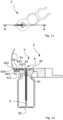
- FIG. 12 shows a cross-sectional view along the line A-A in Fig. 11 .
- the cable passage 6 of this embodiment too consists of a first passage section 61 extending through the first part 41 of the stopper 4 and a second passage section 62 extending through the second part 42 of the stopper 4.
- the first passage section 61 extends from the distal end 411 towards the exterior surface 421 and follows a linear path.
- the second passage section 62 is found in the second part 42 of the stopper 4 and allows the cable 51 to follow a non-linear path.
- the second passage section 62 comprises a first sub-section 621, a second sub-section 622, and a third sub-section 623 each configured to accommodate a section of the cable 51.
- the second subsection 622 also called the first groove above, extends further, into the tab 424, such that the first sub-section 621 and the third sub-section 623, also called the second groove above, are both located in the tab 424.
- the stopper 4 in Figs. 7-12 will be resting loosely on top of the vial. This means that the cable 51 of the sensor 5 cannot be clamped between the vial 3 and the stopper 4 and it is therefore retained only by the engagement with the stopper.
- the tab 424 projects at an angle to length axis of the sensor positioning device, i.e. the straight line on which the stopper 4, the spacer 8, and the connector 9 are arranged. This allows the sensor positioning device to fit into an array of vials as shown in Fig. 9 , where vials in neighbouring rows are off-set in relation to each other. Had the tab projected along length axis and had the same size, it would have collided with the neighbouring vial.
Landscapes
- Engineering & Computer Science (AREA)
- Health & Medical Sciences (AREA)
- Life Sciences & Earth Sciences (AREA)
- Molecular Biology (AREA)
- Mechanical Engineering (AREA)
- General Engineering & Computer Science (AREA)
- Physics & Mathematics (AREA)
- General Physics & Mathematics (AREA)
- Medical Preparation Storing Or Oral Administration Devices (AREA)
- Measurement Of Levels Of Liquids Or Fluent Solid Materials (AREA)
Description
- The present invention relates to a sensor positioning device for use on a vial in a lyophilisation process comprising a stopper configured for closing a neck opening of the vial when mounted thereon, said stopper comprising: a first part configured for extending into the vial and a second part configured for extending over the neck opening of the vial, said first part extending away from the second part and having a distal end opposite the second part, and said second part forming an exterior surface of the stopper and having an outer rim delimiting the stopper in a plane extending in parallel with the exterior surface; a cable passage having a first passage section extending from the distal end towards the exterior surface and allowing a cable of a sensor to pass through the first part of the stopper and a second passage section between the first passage section and the outer rim; and at least one vapour opening allowing vapour to escape from the vial. The invention further relates to a sensor unit and to a method of mounting a sensor in a stopper for a vial thereby creating a sensor unit.
- A reliable monitoring and validation of lyophilisation processes is crucial for example within the pharmaceutical industry, where products must be of high and uniform quality. For this purpose, it is important that the sensors used are positioned correctly within the vials during the entire measuring period, and sensor positioning devices have been designed to ensure that this is the case.
- One sensor positioning device of the type mentioned above, which has found widespread use, is described in
US5,689,895 . This positioning device relies on a cable probe being arranged in a tube extending from the stopper into the cavity of the vial and being fixated in relation to the stopper and/or the vial. The fixation may be achieved either by clamping the cable in the second passage section, which is an open groove extending away from the first passage section towards the outer rim, or by applying an elastic O-ring around the neck of the vial so that the cable is clamped between the vial and the O-ring. In practice, clamping the cable in the cable passage has proven to provide an insufficient protection against pull on the cable, and the O-ring is therefore considered necessary to achieve a reliable positioning. The mounting of the O-ring may, however, be difficult since it usually has to be done in a sterile environment where the operator is required to wear thick gloves. It therefore happens that the probe is pulled out of position during the mounting of the O-ring or that the O-ring is not used. - Another positioning device, which does not require the use of an O-ring, is described in
US5,447,374 . This positioning device instead relies on a clamping device on the first part of the stopper, and there is some concern that the presence of the clamping device within the cavity of the vial may add thermal mass, which may influence on the readings from the sensor. - It is therefore the object of the invention to provide a sensor positioning device, which reduces the risk of displacement of the sensor with a low risk of influencing on the readings of the sensor.
- This object is achieved with a sensor positioning device of the type described above, where the second passage section or a first sub-section thereof extends away from the exterior surface towards the interior surface and is located at a distance from the first passage section in a direction parallel to the exterior surface. This orientation and position of at least a sub-section the second passage section means that when the cable is passed through the cable passage in a tight manner, at least one bend is formed on the cable in addition to the bend occurring where the cable leaves the first passage section. This bend entails that a pull acting on the part of the cable projecting from the sensor positioning device will result in the part of the cable extending from the first passage section to the second passage section or first sub-section thereof being pulled into a tighter contact with the stopper. In contrast a pull acting at an angle to the length direction of the groove serving as the second passage section in
US5,689,895 would result in the cable being pulled out of the groove. In combination with the bend found where the first and second passage sections meet, the bend resulting from the orientation and position of at least a sub-section the second passage section according to the present invention thus serves as a pull relief preventing a displacement of the sensor. Notably, this is achieved using very simple means affecting neither the space available in the vial nor the thermal mass of the sensor positioning device. - In the following, reference will be made primarily to the use of probes, which are essentially cables in themselves, as sensors. It is, however, to be understood that it is also possible to use other types of sensors to which a cable is connected, and where the cable is passed through the cable passage, while the sensor itself does not extend into the second passage section.
- To maximize the effect, the second passage section or the first sub-section thereof may extend in a direction, which is substantially perpendicular to the exterior surface. Any angle of more than 45 degrees between the exterior surface and the second passage section or the first sub-section thereof will, however, provide some relief.
- The elasticity and frictional characteristics of the material used for the stopper will be important factors with respect to determining the pull relief capacity. At present silicone, ethylene propylene diene monomer (EDPM), and other synthetic rubbers are considered advantageous as they will allow the entire stopper to be made from one material. It is, however, within the scope of the invention to make the first and second parts of the stopper from different materials and/or to coat the cable passage wholly or partially with a material providing desired frictional characteristics. It is noted that the friction between the cable passage and the cable will of course also depend on the surface characteristics of the cable and that the use of different types of probes or cables may therefore potentially require the use of different stoppers.
- In one embodiment, the second passage section or the first sub-section thereof extends from an opening in the exterior surface to an opening in the interior surface, i.e. all the way through the second part of the stopper. This will facilitate the insertion of the cable into the cable passage, but it is not a requirement. A more closed cable passage may provide a better protection of the cable and it is even within the scope of the invention to first arrange the cable in the desired shape and then mould the stopper around it. Likewise, the second part of the stopper may be made by arranging the cable in or on a base part and then adding a cover layer onto it, for example by moulding or welding or by means of a glue, an adhesive, or even mechanical fastenings means, such as snap-locking.
- A second sub-section of the second passage section extending away from the first passage section towards the outer rim may be provided to accommodate the cable section extending away from the first passage section. Likewise, a third sub-section of the second passage section may extend from the first sub-section to the outer rim to accommodate another cable section. These sub-sections of the second passage section may help to guide the cable during assembly of a sensor unit and/or keep the cable in place ones mounted thus potentially contributing to the fixation of the cable in relation to the stopper.
- In one embodiment the second sub-section of the second passage section is a groove in the exterior side of the second part of the stopper and the third sub-section of the second passage section is a groove in the interior side of the second part of the stopper. In use this allows the cable to be mounted in at least two different ways, where a first cable section extends from the first passage section in a direction towards the outer rim, a second cable section extends through the second passage section or the first sub-section thereof, and at least one further cable section extending along the second part of the stopper, all cable sections being separated from each other by at least one bend.
- The first way is to let a first cable section extend in a second sub-section of the second passage section from the first passage section to a first sub-section of the second passage section, from there a second cable section extends through the first sub-section of the second passage section, and from there a third cable section extends in a third sub-section from the first sub-section of the second passage section to the outer rim. The first, second, and third cable sections are thus arranged in continuation of each other when seen along the length of the cable, and the path followed by the cable has the overall shape of the letter Z.
- The second way is to let a first cable section extend in a second sub-section of the second passage section from the first passage section to the outer rim, from there a fourth cable section extends from the first cable section across the outer rim to the third cable section, from there the third cable section extends in a third sub-section of the second passage section from the fourth cable section at the outer rim to the first sub-section of the second passage section, and from there the second cable section extends from the third cable section through the first sub-section of the second passage section. When exiting the first sub-section of the second passage section the cable thus passes by the first cable section and the path followed by the cable has the overall shape of the Greek letter a.
- Other ways of mounting the cable, including more complex paths than those described above, are of course possible, but it should be ensured that at least two bends are formed on the cable.
- The second part of the stopper may comprise a tab configured for projecting over an outer perimeter of the neck of the vial in a mounted state, said tab projecting in a direction parallel to the exterior surface of the stopper and substantially in continuation of the second passage section. Such a tab may facilitate handling of the stopper during mounting of the sensor as the presence of the tab may allow a bigger distance between the first passage section and the second passage section or a first sub-section thereof. This will allow longer cable sections and less bending of the cable during the mounting process. Another advantage of such a tab may be that the additional material provides more space for the second passage section, which may particularly be advantageous when it comprises two or more sub-sections, and in one embodiment a third sub-section of the second passage section extends into the tab.
- A tab as described above may also facilitate handling of the assembled sensor unit and the mounting of the sensor unit on the vial.
- In one embodiment the tab is provided with at least one projection on the interior side, said projection being configured for extending down along an outer side of the neck of the vial in the mounted state of the sensor positioning device. If only a single projection is provided, the second passage section may end on an inner side of the projection so that the cable may be sandwiched between the projection and the outer surface of the neck of the vial, or the second passage section may end in an opening in the projection. Alternatively, two projections may be provided closely side-by-side so that the cable existing from the second passage section may be clamped between them, thus providing an extra hold on the cable where it exits the second passage section.
- The sensor positioning device may form part of a sensor unit further comprising a sensor extending from the first part of the stopper and a cable of the sensor. In such a sensor unit a first cable section extends from the first passage section in a direction towards the outer rim and a second cable section extends through the second passage section or the first sub-section thereof, at least one bend being present on the cable between said first and second cable sections, and at least one further cable section, which extends along the second part of the stopper, is separated from the first and second cable sections by at least one bend.
- As described with reference to the sensor positioning device above, the cable may then extend in at least two different ways, which will both result in a fixation of the cable without the need for additional elements. One being where the first cable section extends from the first passage section to a first sub-section of the second passage section, where the second cable section extends through the first sub-section of the second passage section, and where a third cable section extends from the first sub-section of the second passage section to the outer rim, said first, second, and third section being arranged in continuation of each other when seen along the length of the cable. Another being where the first cable section extends from the first passage section to the outer rim, where a fourth cable section extends from the first cable section across the outer rim to the third cable section, where the third cable section extends from the fourth cable section at the outer rim to the first sub-section of the second passage section, and where the second cable section extends from the third cable section through the first sub-section of the second passage section.
- To facilitate the mounting of the cable, the first cable section may extend along the exterior surface of the second part of the stopper and the third cable section extend along the interior surface of the second part of the stopper.
- In a second aspect of the invention the object of the invention is achieved with a method of mounting a sensor including a cable in a stopper for a vial thereby creating a sensor unit for use on a vial in a lyophilisation process, where said stopper is configured for closing an opening in a neck of the vial when mounted thereon, said stopper comprising:
- a first part configured for extending into the vial and a second part configured for extending over the opening of the vial, said first part extending away from the second part and having a distal end opposite the second part, and said second part having an exterior surface forming an exterior surface of the stopper in the mounted state, an interior surface opposite the exterior surface configured for abutting on the neck of the vial, and an outer rim delimiting the stopper in a plane extending in parallel with the exterior surface,
- a cable passage having a first passage section extending from the distal end towards the exterior surface and a second passage section between the first passage section and the outer rim, and
- at least one vapour opening allowing vapour to escape from the vial,
- said method comprising the following steps:
- A) arranging the sensor so that it projects from the distal end of the first part of the stopper, and
- B) passing the cable of the sensor through the cable passage,
- characterized in that step B) comprises the following sub-steps:
- arranging a first cable section so that it extends from the first passage section in a direction towards the outer rim,
- arranging a second cable section so that it extends through the second passage section or a first sub-section thereof, said second passage section or first sub-section thereof extending away from the exterior surface towards the interior surface and being located at a distance from the first passage section in a direction parallel to the exterior surface,
- creating at least one bend on the cable between said first and second cable sections,
- arranging at least one further cable section so that it extends along the second part of the stopper, and
- creating at least one further bend on the cable between the at least one further cable section and the first and/or second cable sections.
- The sub-steps of step B) do not necessarily need to be performed in the order mentioned and it is to be understood that the creation of the bends may include further sub-steps. The insertion of the cable may result in the creation of a soft bend, which is later made sharper by tightening the cable so that it follows the shape of the cable passage and/or surfaces of the stopper.
- In a third aspect of the invention the object of the invention is achieved with a sensor positioning device for use on a vial in a lyophilisation process comprising a stopper configured for closing an opening in a neck of the vial when mounted thereon, a spacer, and a connector, said spacer being positioned between the stopper and the connector, wherein the stopper comprises a first part configured for extending into the vial and a second part configured for extending over the opening of the vial, said first part extending away from the second part and having a distal end opposite the second part, and said second part having an exterior surface forming an exterior surface of the stopper in the mounted state, an interior surface opposite the exterior surface configured for abutting on the neck of the vial, and an outer rim delimiting the stopper in a plane extending in parallel with the exterior surface, and at least one vapour opening allowing vapour to escape from the vial, wherein the spacer comprises two spacer members extending from the stopper substantially in parallel to the exterior surface, said spacer members defining a spacer opening for receiving a spacer vial between them, wherein the connector comprises engagement means for attaching the sensor positioning device to a data collector, and wherein the connector extends from the spacer.
- Consequently, a sensor positioning device is provided where a data collector is spaced away from the vial from which measurements are collected, and where the data collector and the vial can be kept in their intended relative position.
- When a sensor unit including a sensor positioning device is to be used, the sensor positioning device is provided with a sensor and connected to the data collector by the engagement means of the connector. The sensor unit is then moved relative to one or more vials so that the stopper comes into engagement with the neck of a vial with the first part of the stopper projecting into the vial. The sensor unit is preferably arranged so that another vial, herein referred to as a spacer vial, is located in the spacer opening, but it is also possible to leave out the spacer vial and leave the spacer opening empty. The spacer vial or the empty space created by the spacer keeps a distance between the data collector and the vial, within which the sensor is arranged. Thus, the sensor positioning device contributes to reducing the risk of the thermal mass of the data collector influencing the lyophilisation process taking place in the vial, and consequently data collected by the sensor.
- In this description the spacer will be described as having a spacer opening matching the shape and size of one vial, but it is within the scope of the invention to use a spacer configured for accommodating two or more vials. In use the data collector with the sensor unit, the vial in which the sensor is positioned, and the spacer vial are usually pushed into a lyophilisation chamber together with an array of vials. During this process vials may move in relation to each other, and the spacer retains the spacer vial so that it is prevented from unintentionally moving away from the vial in which the sensor is positioned.
- This sensor positioning device is also optimal for robotic handling as both the data collector and the sensor may be connected to the sensor positioning device prior to the sensor positioning device being mounted on a vial. Robotic handling may give a higher through-put and a larger degree of uniformity in how the sensor positioning device is mounted on the vial. The robot needs only to grab the data collector or the sensor positioning device and move them as one unit onto two vials arranged next to each other or a single vial in case the spacer vial is left out. Robotic handling is particularly advantageous considering that manual handling will often require the operator to wear thick gloves, which hampers precision work.
- In an embodiment there is a fixed connection between the stopper, the spacer, and the connector. This prevents the stopper from moving in relation to the spacer and the spacer from moving in relation to the connector, which can in turn be connected to the data collector in a fixed connection. In this way the stopper will substantially be prevented from moving in relation to the data collector once the sensor positioning device is mounted thereon, and the sensor can thus be arranged in the vial by holding on to the data collector only. This will facilitate any handling process and is particularly advantageous in connection with robotic handling as the relative positions of the different components of the sensor positioning device will then always be well-defined. The term "fixed" is only to be understood as preventing mutual movement, not necessarily as a permanent connection. It is, however, presently considered advantageous to make at least the connector and the spacer in one, for example by moulding using a polymer or by milling or cutting it from a block of material. The stopper may need to be made from a different material, for example having a higher elasticity, but may still be connected permanently to the spacer, for example by means of a glue or adhesive or by welding or moulding.
- Above, with reference to the first and second embodiments of the invention, the silicone, ethylene propylene diene monomer (EDPM), and other synthetic rubbers have been described as advantageous materials for the stopper. In the present aspect of the invention, however, the stopper may be configured for resting loosely on the neck of the vial in which case the elasticity of the material is less important, and to facilitate handling of the sensor positioning device, a relatively stiff material may even be preferred. Polyether ether ketone (PEEK) and similar polymers are presently considered promising, particularly for the purpose of making a unitary sensor positioning device, where all elements are made from one piece of material.
- The stopper, the spacer, and the connector of the sensor positioning device may be arranged on a straight line defining a length axis of the sensor positioning device, but a different configuration may be expedient to match an array of vial in which it is to be used.
- In an embodiment a flange is provided at the outer rim of the stopper, said flange extending substantially perpendicular to and away from the exterior surface towards and beyond the interior surface. In a mounted state of the sensor positioning device, the flange will project along an outer surface of the neck of the vial and prevent movement of the stopper relative to the vial, whereas most prior art stoppers rely on the first part of the stopper fitting tightly into the neck of the vial. Tests have shown that it is far easier to fit a stopper with a flange onto a vial, particularly if the first part of the stopper has a smaller diameter than the inner diameter of the neck of the vial and thus does not fit tightly into the vial. The presence of the flange may thus facilitate both manual and robotic handling.
- The flange may extend along the entire outer rim of the stopper and be configured for enclosing the neck of the vial, but it is also possible to have two or more smaller flanges arranged at a distance from each other along the outer rim and extending on different sides of the vial.
- In an embodiment a tab projecting over an outer perimeter of the neck of the vial in a mounted state as described above projects at an angle to the length axis of the sensor positioning device. This may allow the sensor positioning device to fit into an array of vials where vials in neighbouring rows are off-set in relation to each other. In an embodiment, each spacer member is curved so that the spacer opening is substantially circular, corresponding to the circular shape of the necks of most vials. The outer surfaces of the spacer members are preferably also curved, so that the outer shape of the spacer is substantially circular except for the connections to the connector and the stopper. This contributes to the sensor positioning device being able to fit within an array of vials.
- The spacer members may be embodied as walls having major wall surfaces extending perpendicular to the exterior surface of the stopper. This may contribute to guiding a vial into the spacer opening and retaining it during use.
- In an embodiment, the engagement means of the connector comprises two arms configured to provide a snap-connection to the data collector.
- Consequently, simple engagement means are provided, which may provide connection to a wide variety of data collectors. The arms are preferably resilient arms capable of deforming elastically. The data collector may be provided with grooves or recesses configured for engagement with the arms.
- Other examples of engagement means are snap fasteners, male-female connectors, and hook-and-loop type fasteners.
- The features, embodiments, and advantageous of the invention described in reference to one aspect of the invention also applies to the other aspects of the invention.
- It is noted that the interconnection of the stopper, the spacer, and the connector described with reference to the sensor positioning device according to the third aspect of the invention will be advantageous regardless how the stopper is embodied, since it will facilitate handling. Particularly a fixed connection between the stopper, the spacer, and the connector will facilitate handling by robot and thus allow an automation of the handling process, independently of the design of the stopper.
- In the following the invention will be described in more detail with reference to embodiments shown in the drawing, where:
-
Fig. 1 is a cross-sectional view of a sensor unit mounted on a vial, -
Fig. 2 is a perspective view of the sensor unit and vial inFig. 1 , -
Fig. 3 is a perspective view of the stopper used in the sensor unit inFigs 1 and 2 , -
Fig. 4 is a cross-sectional view of another sensor unit mounted on a vial, -
Fig. 5 is a perspective view of the sensor unit and vial inFig. 4 , -
Fig. 6 is a perspective view of the stopper used in the sensor unit inFigs 4 and 5 , -
Fig. 7 is a perspective top view of a sensor positioning device according to another embodiment of the invention, -
Fig. 8 is a perspective bottom of the sensor positioning device inFig. 7 , -
Fig. 9 is a perspective view of the sensor positioning device inFigs 7 and 8 mounted on a vial and a data collector and arranged in an array of vials, -
Fig. 10 is a partial cross-sectional view of the sensor positioning device inFigs 7 and 8 mounted on a vial and a data collector, -
Fig. 11 is a perspective bottom of the sensor positioning device inFigs 7 and 8 , and -
Fig. 12 is cross-sectional view along the line A-A inFig. 11 . - A
sensor unit 1 comprising asensor positioning device 2 mounted on avial 3 for use in a lyophilisation process is shown in a cross-sectionalFig. 1 and in a perspective view inFig. 2 . The sensor positioning device comprising astopper 4 closing the opening in theneck 31 of the vial by being arranged with afirst part 41 extending into the vial and asecond part 42 extending over the opening of the vial. Thesecond part 42 has anexterior surface 421 forming an exterior surface of the stopper in the mounted state, aninterior surface 422 opposite the exterior surface abutting on theneck 31 of the vial, and anouter rim 423 delimiting the stopper in a plane extending in parallel with the exterior surface. - A
sensor 5 extends from adistal end 411 of the first part opposite the second part, and acable 51 of the sensor extends through acable passage 6 in the stopper. In this embodiment thesensor 5 is a probe in the form of a thermo couple comprising two dissimilar electrical conductors forming an electrical junction. Such a sensor may be said to constitute a cable in itself, and in the following reference will therefore only be made to thecable 51. In this embodiment atube 7 extends from thedistal end 411 of thestopper 4 towards the bottom 32 of the vial and supports thecable 51 such that the end of the cable, and hence the sensing point of the sensor, is kept in a well-defined position above the bottom 32 of the vial. - The
cable passage 6 consists of afirst passage section 61 extending through thefirst part 41 of the stopper and asecond passage section 62 extending through thesecond part 42 of the stopper. In this embodiment thetube 7 extends into thefirst passage section 61 and the part of it, which extends away from the stopper, serves as a continuation of thefirst passage section 61. This provides good support for and protection of the probe, but the tube is not strictly necessary, particularly not if using a different type of sensor. - In this embodiment the
stopper 4 and thetube 7 together constitute asensor positioning device 2 as seen inFig. 3 , but a stopper may also constitute a sensor positioning device on its own. - While the
first passage section 61 extends from thedistal end 411 towards theexterior surface 421 and follows a linear path, thesecond passage section 62 is found between the first passage section and the outer rim and allows the cable to follow a non-linear path. In the embodiment shown inFig. 1 thesecond passage section 62 comprises threesub-sections first cable section 511 extends from thefirst passage section 61 to afirst sub-section 621 of the second passage section, asecond cable section 512 extends through thefirst sub-section 621 of the second passage section, and where athird cable section 513 extends from thefirst sub-section 621 of the second passage section to theouter rim 423. The path followed by the cable through the second passage section thus has the overall shape of the letter Z, and is bent at 90 degree angles where it enters and exits thefirst sub-section 621 of the second passage section. - In this embodiment the
first cable section 511 is accommodated in asecond sub-section 622 of the second passage section, which is a groove in the exterior side of the second part of the stopper, as may be seen inFig 3 , and which extends away from the first passage section towards the outer rim. It is, however, also possible to simply let thefirst cable section 511 extend over theexterior surface 421 of the stopper without being inserted in a groove or the like. Likewise, thethird cable section 513 is here accommodated in athird sub-section 623 of the second passage section, which is a groove in the interior side of the second part of the stopper and extends from the first sub-section to the outer rim, but it might instead simply be sandwiched between the interior side of the stopper and neck of the vial in the mounted state. - In the embodiment shown in
Figs. 1-3 the second part of the stopper comprises atab 424 projecting in a direction parallel to the exterior surface and over theneck 31 of thevial 3 in a mounted state. The tab projects substantially in continuation of the second passage section and thethird sub-section 623 continues into the tab. As best seen inFigs. 1 and 3 the presence of thetab 424 allows thatfirst sub-section 621 of the second passage section to be provided at a bigger distance D from thefirst passage section 61 than would otherwise have been possible considering that a certain amount of material must be present between the first sub-section and theouter rim 423. This allows the second andthird sub-sections cable 51 on thestopper 4. Another advantage of thetab 424 is that it may facilitate handling of the sensor unit. - The
tab 424 is here provided with twoprojection 425 on the interior side, one on each side of thethird sub-section 623 of the second passage section. In the mounted state these projections extend down along anouter side 33 of theneck 31 of thevial 3 as is seen inFig. 1 , thus potentially contributing to the positioning of the sensor unit in relation to the vial. The two projections further serve as a fixation for thecable 51, which can be clamped between them where it exits the stopper. In this way they contribute to keeping the cable in the third sub-section of the second passage section and they may further provide a strain relief reducing the risk of damages to the cable. The latter particularly applies if thestopper 4 or at least theprojections 425 are made from an elastic material, such as rubber. - Turning now to
Figs 4-6 a second embodiment of the invention is shown.Figs 4-6 correspond toFigs 1-3 except for showing a different embodiment, and the same reference numbers have been used for features being identical and/or having the same function. In the following, only the features which are different from the embodiment inFigs. 1-3 will be described. - In
Figs 4-6 thesecond sub-section 622 of thecable passage 6 extends all the way from thefirst passage section 61 to theouter rim 423 of thesecond part 42 of thestopper 4 and afourth sub-section 624 of the second passage section extends across the outer rim down to thethird sub-section 623. The cable extends the from the first passage section throughsecond sub-section 622, then down through thefourth sub-section 624 across the outer rim, then through the third cable section, and finally through thefirst sub-section 621 to the exterior side. In this embodiment the cable is bent three times, each over approximately 90 degree, and the path followed by the cable resembles the Greek letter α. - As the cable exits the stopper at the exterior side there is no need for the clamping function of the
projections 425 described with reference toFigs 1-3 and they have therefore been left out in this embodiment. - As is best seen in
Figs 3 and6 thecable passages 6 are in bothstoppers 4 independent of thevapour openings 44, which are configured for allowing vapour to escape from the vial during a lyophilisation process, so that escape of vapour is not affected by the presence of the cable. - A
sensor positioning device 2 according to another embodiment of the invention is shown in a perspective top view inFig. 7 and in a perspective bottom view inFig. 8 . The same reference numbers have been used for features being identical and/or having the same function as disclosed in relation toFigs 1-6 . - The
sensor positioning device 2 comprising astopper 4 for closing an opening in aneck 31 of avial 3, said stopper comprising afirst part 41 configured to extend into thevial 3 and asecond part 42 configured to extend over the opening of thevial 3. Thesecond part 42 has anexterior surface 421 forming anexterior surface 421 of thestopper 4 in the mounted state and an oppositeinterior surface 422 configured for abutting theneck 31 of thevial 3. Thesecond part 42 further comprising anouter rim 423 delimiting thestopper 4 in a plane extending in parallel with theexterior surface 421. Aflange 427 is provided at theouter rim 423 and extends perpendicular to and away from theexterior surface 421 and beyond theinterior surface 422. Theflange 427 in the mounted state encloses theneck 31 of thevial 3 with little to no clearance as seen inFig. 10 . Theflange 427 may facilitate a correct positioning of thesensor positioning device 2 and in the mounted state it may limit movement of thesensor positioning device 2 relative to thevial 3 in a plane extending in parallel with theinterior surface 422. - The
stopper 4 further comprisesvapour openings 44, which are configured for allowing vapour to escape from thevial 3 during a lyophilisation process. - A
first groove 622 is formed in theexterior surface 421. The first groove is configured for accommodating asensor 5, a part of the sensor, or acable 51 of a sensor as described with reference to thesecond sub-section 622 inFigs. 1-6 . - In the embodiment shown in
Figs 7-8 thesecond part 42 of thestopper 4 comprises atab 424 projecting in a direction parallel to theexterior surface 421. Thetab 424 projects over a perimeter of theneck 31 of thevial 3 in a mounted state of thesensor positioning device 2. At least part of thefirst groove 622 extends into a first tab surface of thetab 424. A second tab surface of thetab 424 is provided with asecond groove 623 for accommodating asensor 5 orcable 51 as also described above with reference to thethird sub-section 623 inFigs. 1-6 . The second tab surface of the tab is opposite the first tab surface of thetab 424. The first and second grooves are interconnected by apassage 621 corresponding to thefirst sub-section 621 inFigs. 1-6 as seen inFig. 12 . - In the shown embodiment a
tube 7 extends from adistal end 411 of thefirst part 41 of thestopper 4. Thetube 7 is configured to extend towards the bottom 32 of thevial 3, on which thesensor positioning device 2 is mounted as shown inFig. 10 . Thetube 7 is configured for supporting acable 51 forming at least part of asensor 5, such that the end of the cable forming a sensing point of thesensor 5 is kept in a well-defined position above a bottom 32 of the vial as shown inFig. 12 . Thetube 7 may be provided as an integral part of thefirst part 41 of the stopper or be connected to thefirst part 41, e.g. by press fitting thetube 7 into a sleeve formed by thefirst part 41. - The
sensor positioning device 2 further comprises aspacer 8 extending from thestopper 4. Thespacer 8 comprises twospacer members 83, each being curved so that aspacer opening 84 with a circular shape is provided between them. Thespacer members 83 are here embodied as spacer walls having major wall surfaces extending perpendicular to theexterior surface 421 of the stopper. - In the shown embodiment a
first surface 81 of the spacer extends in continuation of theexterior surface 421 of thesecond part 42 of the stopper. Alternatively, thefirst surface 81 may extend from thestopper 4 in a plane parallel to a plane defined by theexterior surface 421. Opposite thefirst surface 81 is asecond surface 82. - The
spacer opening 84 is configured for receiving at least part of aspacer vial 30 within thespacer opening 84 as shown inFigs 9 and 10 . The spacer vial is a vial placed in the proximity of thevial 3 on which thestopper 4 is to be mounted, e.g. next to thevial 3 on which thestopper 4 is to be mounted. In the mounted condition of thesensor positioning device 2, thespacer wall 83 limits movement of thespacer vial 30 received within thespacer opening 84 relative to thesensor positioning device 2. - The
sensor positioning device 2 further comprises aconnector 9. Theconnector 9 is configured for connecting thesensor positioning device 2 to adata collector 10 as shown inFigs. 9 and 10 . Theconnector 9 has twoarms arms semi-circular receiving space 93 is formed between them. The receivingspace 93 is configured to receive at least part of thedata collector 10, so thedata collector 10 is prevented from moving relative to thesensor positioning device 2, at least within one plane. Thearms second surface 82 of the spacer. In the shown embodiment at least part of thearms second surface 82. Thearms data collector 10 and thesensor positioning device 2. - The
connector 9, thespacer 8 and thestopper 4 are in the shown embodiment integrally formed, thus preventing relative movement between theconnector 9, thespacer 8 and thestopper 4. The integral connection is provided by making theconnector 9, thespacer 8 and thestopper 4 from the same material as one unitary item, for example by milling, cutting or moulding. Alternatively, theconnector 9, thespacer 8 and thestopper 4 may be connected to one another for example by gluing or welding. - In the embodiment shown, the
stopper 4, thespacer 8, and theconnector 9 of thesensor positioning device 2 are arranged on a straight line defining a length axis of the sensor positioning device, but a different configuration is possible if expedient to match the position of the vial in the array, where the sensor positioning device is to be used. - Turning now to
Figs 9 and 10 showing a perspective view of thesensor positioning device 2 inFigs 7 and 8 mounted on avial 3 and adata collector 10, here in the form of a data logger. - Here the
first part 41 of thestopper 4 has been introduced into thevial 3 and thetube 7 extending from thefirst part 41 guides thesensor 5 to a position close to the bottom of thevial 3. - The
second part 42 abuts aneck 31 of thevial 3 and covers the opening therein. Theexterior surface 421 of thesecond part 42 faces away from thevial 3, theinterior surface 422 abuts theneck 31 of thevial 3, and theflange 427 extends downwards along outer sides of theneck 31 of thevial 3, enclosing theneck 31. Theflange 427 limits movement of thevial 3 relative to thesensor positioning device 2. - A
spacer vial 30 is received within thespacer opening 84 and thespacer wall 83 encloses the neck of thespacer vial 30. Thespacer wall 83 ensures that thespacer vial 30 does not move excessively relative to thesensor positioning device 2. As is noticeable onFig. 10 , a small clearance is present between the part of thespacer vial 30 received within thespacer opening 84 and thespacer wall 83. Furthermore, thesecond surface 82 of thespacer 8 does not contact thespacer vial 30, hence no contact is present between thespacer 8 and thespacer vial 30. This allows for thesensor positioning device 2 to be lowered down over thespacer vial 30 or for the vial to be inserted into thespacer opening 84 with virtually no frictional resistance, thus facilitating handling. This applies regardless of the embodiment of the stopper and the connector. In other embodiments, thespacer 8 may be configured to abut thespacer vial 30, e.g. thesecond surface 82 being configured to abut thespacer vial 30, thereby potentially indicating when the spacer vial and the sensor positioning device are correctly positioned in relation to each other. - Extending from the
spacer 8 is thearms connector 9, only one being visible onFigs 9 and 10 . Thearms data collector 10 in a snap connection provided by resiliency in thearms data collector 10 is thereby distanced from thevial 3 on which measurements are collected. - Referring now to
Figs 11 and 12 , whereFig. 12 shows a cross-sectional view along the line A-A inFig. 11 . - As described with reference to
Figs. 1-3 , thecable passage 6 of this embodiment too consists of afirst passage section 61 extending through thefirst part 41 of thestopper 4 and asecond passage section 62 extending through thesecond part 42 of thestopper 4. Thefirst passage section 61 extends from thedistal end 411 towards theexterior surface 421 and follows a linear path. Thesecond passage section 62 is found in thesecond part 42 of thestopper 4 and allows thecable 51 to follow a non-linear path. In the embodiment shown inFig. 12 thesecond passage section 62 comprises afirst sub-section 621, asecond sub-section 622, and athird sub-section 623 each configured to accommodate a section of thecable 51. The only differences in relation to the embodiment inFigs. 1-3 is that thesecond subsection 622, also called the first groove above, extends further, into thetab 424, such that thefirst sub-section 621 and thethird sub-section 623, also called the second groove above, are both located in thetab 424. - While, in the embodiment in
Figs. 1-6 , thethird cable section 513 is potentially in contact with the vial and can be clamped between thevial 3 and thestopper 4 due to friction between thefirst part 41 of the stopper and the neck of the vial, thestopper 4 inFigs. 7-12 will be resting loosely on top of the vial. This means that thecable 51 of thesensor 5 cannot be clamped between thevial 3 and thestopper 4 and it is therefore retained only by the engagement with the stopper. - In the embodiment shown, the
tab 424 projects at an angle to length axis of the sensor positioning device, i.e. the straight line on which thestopper 4, thespacer 8, and theconnector 9 are arranged. This allows the sensor positioning device to fit into an array of vials as shown inFig. 9 , where vials in neighbouring rows are off-set in relation to each other. Had the tab projected along length axis and had the same size, it would have collided with the neighbouring vial. - The advantages achieved by the interconnection of the
stopper 4, thespacer 8, and theconnector 9 will be present even if the stopper is embodied differently, both with respect to the overall shape of thestopper 4 and with respect to the shape of thecable passage 6.
Claims (15)
- A sensor positioning device (2) for use on a vial (3) in a lyophilisation process comprising a stopper (4) configured for closing an opening in a neck (31) of the vial when mounted thereon, said stopper comprising:a first part (41) configured for extending into the vial (3) and a second part (42) configured for extending over the opening of the vial, said first part extending away from the second part and having a distal end (411) opposite the second part, and said second part having an exterior surface (421) forming an exterior surface of the stopper (4) in the mounted state, an interior surface (422) opposite the exterior surface configured for abutting on the neck (31) of the vial (3), and an outer rim (423) delimiting the stopper in a plane extending in parallel with the exterior surface (421),a cable passage (6) having a first passage section (61) extending from the distal end (411) towards the exterior surface (421) and allowing a cable (51) of a sensor (5) to pass through the first part (41) of the stopper (4) and a second passage section (62) between the first passage section (61) and the outer rim (423), andat least one vapour opening allowing vapour to escape from the vial (3),characterized in that the second passage section (62) or a first sub-section (621) thereof extends away from the exterior surface (421) towards the interior surface (422) and is located at a distance from the first passage section (61) in a direction parallel to the exterior surface (421).
- A sensor positioning device (2) according to claim 1, wherein the second passage section (62) or the first sub-section (621) thereof extends in a direction, which is perpendicular to the exterior surface (421).
- A sensor positioning device (2) according to claim 1 or 2, wherein the second passage section (62) or the first sub-section (621) thereof extends from an opening in the exterior surface (421) to an opening in the interior surface (422).
- A sensor positioning device (2) according to one or more of the preceding claims, wherein a second sub-section (622) of the second passage section (62) extends away from the first passage section (61) towards the outer rim (423).
- A sensor positioning device (2) according to one or more of the preceding claims, wherein a third sub-section (623) of the second passage section (62) extends from the first sub-section (621) to the outer rim (423).
- A sensor positioning device (2) according to claim 4 or 5, wherein a second sub-section (622) of the second passage section (62) is a groove in the exterior side of the second part (42) of the stopper (4) and/or wherein a third sub-section (623) of the second passage section (62) is a groove in the interior side of the second part of the stopper.
- A sensor positioning device (2) according to one or more of the preceding claims, wherein the second part (42) of the stopper (4) comprises a tab (424) configured for projecting over the neck (31) of the vial (3) in a mounted state, said tab projecting in a direction parallel to the exterior surface (421) of the stopper and substantially in continuation of the second passage section (62).
- A sensor positioning device (2) according to claims 5 and 7, where the third sub-section (623) of the second passage section (62) extends into the tab (424).
- A sensor positioning device (2) according to claim 7 or 8, where tab (424) is provided with at least one projection (425) on the interior side, said projection being configured for extending down along an outer side of the neck (31) of the vial (3) in the mounted state of the sensor positioning device.
- A sensor positioning device (2) according to one or more of the preceding claims, further comprising a spacer (8) and a connector (9), wherein the spacer (8) is positioned between the stopper (4) and the connector (9), wherein the spacer (8) comprises two spacer members (83) extending from the stopper substantially in parallel to the exterior surface (421), said spacer members (83) defining a spacer opening (84) for receiving a spacer vial (30) between them, and wherein the connector (9) comprises engagement means for attaching the sensor positioning device (2) to a data collector (10), and wherein the connector (9) extends from the spacer (8).
- A sensor unit (1) comprising a sensor positioning device (2) according to one or more of the preceding claims, a sensor (5) extending from the first part (41) of the stopper (4), and a cable (51) of the sensor, where a first cable section (511) extends from the first passage section (61) in a direction towards the outer rim (423) and where a second cable section (512) extends through the second passage section (62) or the first sub-section (621) thereof, at least one bend being present on the cable (51) between said first and second cable sections (511, 512), and in where at least one further cable section, which extends along the second part (42) of the stopper (4), is separated from the first and second cable sections (511, 512) by at least one bend.
- A sensor unit (1) according to claim 11, where the first cable section (511) extends from the first passage section (61) to a first sub-section (621) of the second passage section (62), where the second cable section (512) extends through the first sub-section (621) of the second passage section (62), and where a third cable section (513) extends from the first sub-section (621) of the second passage section (62) to the outer rim (423), said first, second, and third section (511, 512, 513) being arranged in continuation of each other when seen along the length of the cable (51).
- A sensor unit (1) according to claim 11, where the first cable section (511) extends from the first passage section (61) to the outer rim (423), where a fourth cable section extends from the first cable section (511) across the outer rim (423) to a third cable section (513), where the third cable section extends from the fourth cable section at the outer rim (423) to the first sub-section (621) of the second passage section (62), and where the second cable section (512) extends from the third cable section (513) through the first sub-section (621) of the second passage section (62).
- A sensor unit (1) according to claim 12 or 13, where the first cable section (511) extends along the exterior surface (421) of the second part (42) of the stopper (4) and where the third cable section (513) extends along the interior surface (422) of the second part of the stopper.
- A method of mounting a sensor (5) including a cable (51) in a stopper (4) for a vial (3) thereby creating a sensor unit (1) for use on a vial in a lyophilisation process, where said stopper is configured for closing an opening in a neck (31) of the vial (3) when mounted thereon, said stopper (4) comprising:a first part (41) configured for extending into the vial (3) and a second part (42) configured for extending over the opening of the vial, said first part extending away from the second part and having a distal end (411) opposite the second part, and said second part having an exterior surface (421) forming an exterior surface of the stopper (4) in the mounted state, an interior surface (422) opposite the exterior surface configured for abutting on the neck (31) of the vial (3), and an outer rim (423) delimiting the stopper in a plane extending in parallel with the exterior surface (421),a cable passage (6) having a first passage section (61) extending from the distal end (411) towards the exterior surface (421) and a second passage section (62) between the first passage section (61) and the outer rim (423), andat least one vapour opening allowing vapour to escape from the vial (3),said method comprising the following steps:A) arranging the sensor (5) so that it projects from the distal end (411) of the first part (41) of the stopper (4), andB) passing the cable (51) of the sensor (5) through the cable passage (6),where step B) comprises the following sub-steps:arranging a first cable section (511) so that it extends from the first passage section (61) in a direction towards the outer rim (423),arranging a second cable section (512) so that it extends through the second passage section (62) or a first sub-section (621) thereof, said second passage section (62) or first sub-section (621) thereof extending away from the exterior surface (421) towards the interior surface (422) and being located at a distance from the first passage section (61) in a direction parallel to the exterior surface,creating at least one bend on the cable (51) between said first and second cable sections (511, 512),arranging at least one further cable section so that it extends along the second part (42) of the stopper (4), andcreating at least one further bend on the cable (51) between the at least one further cable section and the first and/or second cable sections (511, 512).
Applications Claiming Priority (2)
| Application Number | Priority Date | Filing Date | Title |
|---|---|---|---|
| PCT/DK2020/050166 WO2021249597A1 (en) | 2020-06-10 | 2020-06-10 | A sensor positioning device for use on a vial in a lyophilisation process, a sensor unit, and a method of mounting a sensor in a stopper for a vial |
| PCT/DK2020/050323 WO2021249598A1 (en) | 2020-06-10 | 2020-11-23 | Sensor positioning device for use on a vial in a lyophilisation process, sensor unit and method of mounting a sensor in a stopper for a vial |
Publications (3)
| Publication Number | Publication Date |
|---|---|
| EP3948128A1 EP3948128A1 (en) | 2022-02-09 |
| EP3948128B1 true EP3948128B1 (en) | 2023-12-13 |
| EP3948128C0 EP3948128C0 (en) | 2023-12-13 |
Family
ID=71620114
Family Applications (1)
| Application Number | Title | Priority Date | Filing Date |
|---|---|---|---|
| EP20811974.3A Active EP3948128B1 (en) | 2020-06-10 | 2020-11-23 | Sensor positioning device for use on a vial in a lyophilisation process, sensor unit and method of mounting a sensor in a stopper for a vial |
Country Status (3)
| Country | Link |
|---|---|
| US (1) | US12072148B2 (en) |
| EP (1) | EP3948128B1 (en) |
| WO (2) | WO2021249597A1 (en) |
Cited By (1)
| Publication number | Priority date | Publication date | Assignee | Title |
|---|---|---|---|---|
| US20220307766A1 (en) * | 2020-06-10 | 2022-09-29 | Ellab A/S | A Sensor Positioning Device for Use on a Vial in a Lyophilisation Process, a Sensor Unit, and a Method of Mounting a Sensor in a Stopper for a Vial |
Families Citing this family (1)
| Publication number | Priority date | Publication date | Assignee | Title |
|---|---|---|---|---|
| WO2025094216A1 (en) * | 2023-11-02 | 2025-05-08 | Resontech S.R.L. | Lyophilization afferent system |
Family Cites Families (14)
| Publication number | Priority date | Publication date | Assignee | Title |
|---|---|---|---|---|
| US3795986A (en) * | 1971-12-13 | 1974-03-12 | Cenco Medical Health Supply Co | Modular compartment sublimator |
| US4609102A (en) * | 1984-12-31 | 1986-09-02 | Blum Alvin S | Plastic film bag lyophilization system |
| US4966469A (en) * | 1990-01-02 | 1990-10-30 | Fts Systems, Inc. | Positioning device for temperature sensor in freeze drying |
| US5447374A (en) | 1994-01-03 | 1995-09-05 | Fts Systems, Inc. | Positioning device for temperature sensor in freeze drying |
| DE69412291T2 (en) * | 1994-08-19 | 1998-12-03 | W.L. Gore & Associates, Inc., Newark, Del. | VENTILATED GLASS BOTTLE FOR FREEZING DRYING AND METHOD FOR REDUCING CONTAMINATION OF FREEZING DRY PRODUCTS |
| CA2231363A1 (en) * | 1995-09-07 | 1997-03-13 | Elan Medical Technologies Limited | Medicament conversion system |
| WO1997011155A1 (en) * | 1995-09-22 | 1997-03-27 | Government Of The United States Of America, Represented By The Secretary Of The Department Of Health And Human Services | Container for drying biological samples, method of making such container, and method of using same |
| US5689895A (en) | 1996-10-31 | 1997-11-25 | S.P. Industries, Inc., The Virtis Division | Probe positioning device for a flask freeze drying |
| US6907679B2 (en) * | 1998-11-12 | 2005-06-21 | Qlt Usa, Inc. | Method for lyophilizing an active agent |
| US7520670B2 (en) * | 2005-04-26 | 2009-04-21 | John Jeffrey Schwegman | Wireless temperature sensing system for lyophilization processes |
| WO2007127286A2 (en) * | 2006-04-24 | 2007-11-08 | Medical Instill Technologies, Inc. | Needle penetrable and laser resealable lyophilization device and related method |
| CN112639162A (en) * | 2018-03-27 | 2021-04-09 | Sio2医药产品公司 | Vessel, container and surface coated with a water barrier coating |
| WO2021249597A1 (en) * | 2020-06-10 | 2021-12-16 | Ellab A/S | A sensor positioning device for use on a vial in a lyophilisation process, a sensor unit, and a method of mounting a sensor in a stopper for a vial |
| EP4168068B1 (en) * | 2020-06-22 | 2026-04-22 | SiO2 Medical Products, Inc. | Atomic layer deposition coated pharmaceutical packaging and improved syringes and vials, e.g. for lyophilized/cold-chain drugs/vaccines |
-
2020
- 2020-06-10 WO PCT/DK2020/050166 patent/WO2021249597A1/en not_active Ceased
- 2020-11-23 EP EP20811974.3A patent/EP3948128B1/en active Active
- 2020-11-23 WO PCT/DK2020/050323 patent/WO2021249598A1/en not_active Ceased
- 2020-11-23 US US17/309,969 patent/US12072148B2/en active Active
Cited By (2)
| Publication number | Priority date | Publication date | Assignee | Title |
|---|---|---|---|---|
| US20220307766A1 (en) * | 2020-06-10 | 2022-09-29 | Ellab A/S | A Sensor Positioning Device for Use on a Vial in a Lyophilisation Process, a Sensor Unit, and a Method of Mounting a Sensor in a Stopper for a Vial |
| US12072148B2 (en) * | 2020-06-10 | 2024-08-27 | Ellab A/S | Sensor positioning device for use on a vial in a lyophilisation process, a sensor unit, and a method of mounting a sensor in a stopper for a vial |
Also Published As
| Publication number | Publication date |
|---|---|
| US12072148B2 (en) | 2024-08-27 |
| WO2021249597A1 (en) | 2021-12-16 |
| EP3948128A1 (en) | 2022-02-09 |
| WO2021249598A1 (en) | 2021-12-16 |
| EP3948128C0 (en) | 2023-12-13 |
| US20220307766A1 (en) | 2022-09-29 |
Similar Documents
| Publication | Publication Date | Title |
|---|---|---|
| US12072148B2 (en) | Sensor positioning device for use on a vial in a lyophilisation process, a sensor unit, and a method of mounting a sensor in a stopper for a vial | |
| US10962158B2 (en) | Connection system | |
| US4392344A (en) | Chain-link cable carrier | |
| US5720653A (en) | Universal polishing fixture for polishing optical fiber connectors | |
| CA2552619C (en) | Button style cord connector | |
| JP2018071789A (en) | Pin and grommet fastener accommodating bidirectional offset and related method | |
| US5940560A (en) | Optical connection plug | |
| US20090266945A1 (en) | Clamping element for holding at least one object, in particular a cable | |
| CA2436283C (en) | Latching and assembly structure of a cover and duct base in a wiring duct assembly | |
| JP7447180B2 (en) | Temperature measurement device for measuring the temperature of the terminals of electrical connectors | |
| US8625953B2 (en) | Optical fiber ribbon holding member, optical fiber ribbon holding method, optical fiber ribbon bundle and holding member fixture | |
| WO2011067163A2 (en) | Gel sealing device | |
| US9411117B1 (en) | Cable management device | |
| US6249635B1 (en) | Universal fiber optic splice holder | |
| JP2007516370A (en) | Enclosure | |
| US4632489A (en) | Hood for electronic cable connector | |
| US7033074B2 (en) | Temperature-sensor fixing holder | |
| JP4648548B2 (en) | Connection part of long body cover | |
| US20210172781A1 (en) | Interface for connecting a fluid measurement point and a modular fluid measurement system | |
| CN219523798U (en) | install the system | |
| EP3564563B1 (en) | Holding device which can be fixed to a wall for holding a tube | |
| US6904670B2 (en) | Frame jig for a connector | |
| JP6127009B2 (en) | Physical quantity measuring device | |
| EP2678647B1 (en) | Improvements related to respiratory apparatus | |
| CN211576390U (en) | A temperature sensing bulb fixing device and an air conditioner |
Legal Events
| Date | Code | Title | Description |
|---|---|---|---|
| STAA | Information on the status of an ep patent application or granted ep patent |
Free format text: STATUS: UNKNOWN |
|
| STAA | Information on the status of an ep patent application or granted ep patent |
Free format text: STATUS: THE INTERNATIONAL PUBLICATION HAS BEEN MADE |
|
| PUAI | Public reference made under article 153(3) epc to a published international application that has entered the european phase |
Free format text: ORIGINAL CODE: 0009012 |
|
| STAA | Information on the status of an ep patent application or granted ep patent |
Free format text: STATUS: REQUEST FOR EXAMINATION WAS MADE |
|
| 17P | Request for examination filed |
Effective date: 20210708 |
|
| AK | Designated contracting states |
Kind code of ref document: A1 Designated state(s): AL AT BE BG CH CY CZ DE DK EE ES FI FR GB GR HR HU IE IS IT LI LT LU LV MC MK MT NL NO PL PT RO RS SE SI SK SM TR |
|
| STAA | Information on the status of an ep patent application or granted ep patent |
Free format text: STATUS: EXAMINATION IS IN PROGRESS |
|
| RIN1 | Information on inventor provided before grant (corrected) |
Inventor name: HANSEN, RASMUS |
|
| 17Q | First examination report despatched |
Effective date: 20220214 |
|
| GRAP | Despatch of communication of intention to grant a patent |
Free format text: ORIGINAL CODE: EPIDOSNIGR1 |
|
| STAA | Information on the status of an ep patent application or granted ep patent |
Free format text: STATUS: GRANT OF PATENT IS INTENDED |
|
| INTG | Intention to grant announced |
Effective date: 20230704 |
|
| DAV | Request for validation of the european patent (deleted) | ||
| DAX | Request for extension of the european patent (deleted) | ||
| GRAS | Grant fee paid |
Free format text: ORIGINAL CODE: EPIDOSNIGR3 |
|
| GRAA | (expected) grant |
Free format text: ORIGINAL CODE: 0009210 |
|
| STAA | Information on the status of an ep patent application or granted ep patent |
Free format text: STATUS: THE PATENT HAS BEEN GRANTED |
|
| AK | Designated contracting states |
Kind code of ref document: B1 Designated state(s): AL AT BE BG CH CY CZ DE DK EE ES FI FR GB GR HR HU IE IS IT LI LT LU LV MC MK MT NL NO PL PT RO RS SE SI SK SM TR |
|
| REG | Reference to a national code |
Ref country code: GB Ref legal event code: FG4D |
|
| REG | Reference to a national code |
Ref country code: CH Ref legal event code: EP |
|
| REG | Reference to a national code |
Ref country code: DE Ref legal event code: R096 Ref document number: 602020022822 Country of ref document: DE |
|
| REG | Reference to a national code |
Ref country code: IE Ref legal event code: FG4D |
|
| U01 | Request for unitary effect filed |
Effective date: 20240110 |
|
| U07 | Unitary effect registered |
Designated state(s): AT BE BG DE DK EE FI FR IT LT LU LV MT NL PT SE SI Effective date: 20240118 |
|
| PG25 | Lapsed in a contracting state [announced via postgrant information from national office to epo] |
Ref country code: GR Free format text: LAPSE BECAUSE OF FAILURE TO SUBMIT A TRANSLATION OF THE DESCRIPTION OR TO PAY THE FEE WITHIN THE PRESCRIBED TIME-LIMIT Effective date: 20240314 |
|
| PG25 | Lapsed in a contracting state [announced via postgrant information from national office to epo] |
Ref country code: ES Free format text: LAPSE BECAUSE OF FAILURE TO SUBMIT A TRANSLATION OF THE DESCRIPTION OR TO PAY THE FEE WITHIN THE PRESCRIBED TIME-LIMIT Effective date: 20231213 |
|
| PG25 | Lapsed in a contracting state [announced via postgrant information from national office to epo] |
Ref country code: GR Free format text: LAPSE BECAUSE OF FAILURE TO SUBMIT A TRANSLATION OF THE DESCRIPTION OR TO PAY THE FEE WITHIN THE PRESCRIBED TIME-LIMIT Effective date: 20240314 Ref country code: ES Free format text: LAPSE BECAUSE OF FAILURE TO SUBMIT A TRANSLATION OF THE DESCRIPTION OR TO PAY THE FEE WITHIN THE PRESCRIBED TIME-LIMIT Effective date: 20231213 |
|
| PG25 | Lapsed in a contracting state [announced via postgrant information from national office to epo] |
Ref country code: RS Free format text: LAPSE BECAUSE OF FAILURE TO SUBMIT A TRANSLATION OF THE DESCRIPTION OR TO PAY THE FEE WITHIN THE PRESCRIBED TIME-LIMIT Effective date: 20231213 Ref country code: NO Free format text: LAPSE BECAUSE OF FAILURE TO SUBMIT A TRANSLATION OF THE DESCRIPTION OR TO PAY THE FEE WITHIN THE PRESCRIBED TIME-LIMIT Effective date: 20240313 Ref country code: HR Free format text: LAPSE BECAUSE OF FAILURE TO SUBMIT A TRANSLATION OF THE DESCRIPTION OR TO PAY THE FEE WITHIN THE PRESCRIBED TIME-LIMIT Effective date: 20231213 |
|
| PG25 | Lapsed in a contracting state [announced via postgrant information from national office to epo] |
Ref country code: IS Free format text: LAPSE BECAUSE OF FAILURE TO SUBMIT A TRANSLATION OF THE DESCRIPTION OR TO PAY THE FEE WITHIN THE PRESCRIBED TIME-LIMIT Effective date: 20240413 |
|
| PG25 | Lapsed in a contracting state [announced via postgrant information from national office to epo] |
Ref country code: CZ Free format text: LAPSE BECAUSE OF FAILURE TO SUBMIT A TRANSLATION OF THE DESCRIPTION OR TO PAY THE FEE WITHIN THE PRESCRIBED TIME-LIMIT Effective date: 20231213 |
|
| PG25 | Lapsed in a contracting state [announced via postgrant information from national office to epo] |
Ref country code: SK Free format text: LAPSE BECAUSE OF FAILURE TO SUBMIT A TRANSLATION OF THE DESCRIPTION OR TO PAY THE FEE WITHIN THE PRESCRIBED TIME-LIMIT Effective date: 20231213 |
|
| PG25 | Lapsed in a contracting state [announced via postgrant information from national office to epo] |
Ref country code: SM Free format text: LAPSE BECAUSE OF FAILURE TO SUBMIT A TRANSLATION OF THE DESCRIPTION OR TO PAY THE FEE WITHIN THE PRESCRIBED TIME-LIMIT Effective date: 20231213 Ref country code: SK Free format text: LAPSE BECAUSE OF FAILURE TO SUBMIT A TRANSLATION OF THE DESCRIPTION OR TO PAY THE FEE WITHIN THE PRESCRIBED TIME-LIMIT Effective date: 20231213 Ref country code: RO Free format text: LAPSE BECAUSE OF FAILURE TO SUBMIT A TRANSLATION OF THE DESCRIPTION OR TO PAY THE FEE WITHIN THE PRESCRIBED TIME-LIMIT Effective date: 20231213 Ref country code: IS Free format text: LAPSE BECAUSE OF FAILURE TO SUBMIT A TRANSLATION OF THE DESCRIPTION OR TO PAY THE FEE WITHIN THE PRESCRIBED TIME-LIMIT Effective date: 20240413 Ref country code: CZ Free format text: LAPSE BECAUSE OF FAILURE TO SUBMIT A TRANSLATION OF THE DESCRIPTION OR TO PAY THE FEE WITHIN THE PRESCRIBED TIME-LIMIT Effective date: 20231213 |
|
| PG25 | Lapsed in a contracting state [announced via postgrant information from national office to epo] |
Ref country code: PL Free format text: LAPSE BECAUSE OF FAILURE TO SUBMIT A TRANSLATION OF THE DESCRIPTION OR TO PAY THE FEE WITHIN THE PRESCRIBED TIME-LIMIT Effective date: 20231213 |
|
| PG25 | Lapsed in a contracting state [announced via postgrant information from national office to epo] |
Ref country code: PL Free format text: LAPSE BECAUSE OF FAILURE TO SUBMIT A TRANSLATION OF THE DESCRIPTION OR TO PAY THE FEE WITHIN THE PRESCRIBED TIME-LIMIT Effective date: 20231213 |
|
| REG | Reference to a national code |
Ref country code: DE Ref legal event code: R097 Ref document number: 602020022822 Country of ref document: DE |
|
| PLBE | No opposition filed within time limit |
Free format text: ORIGINAL CODE: 0009261 |
|
| STAA | Information on the status of an ep patent application or granted ep patent |
Free format text: STATUS: NO OPPOSITION FILED WITHIN TIME LIMIT |
|
| 26N | No opposition filed |
Effective date: 20240916 |
|
| U21 | Renewal fee for the european patent with unitary effect paid with additional fee |
Year of fee payment: 5 Effective date: 20241218 |
|
| REG | Reference to a national code |
Ref country code: CH Ref legal event code: PL |
|
| PG25 | Lapsed in a contracting state [announced via postgrant information from national office to epo] |
Ref country code: MC Free format text: LAPSE BECAUSE OF FAILURE TO SUBMIT A TRANSLATION OF THE DESCRIPTION OR TO PAY THE FEE WITHIN THE PRESCRIBED TIME-LIMIT Effective date: 20231213 |
|
| REG | Reference to a national code |
Ref country code: CH Ref legal event code: PL |
|
| GBPC | Gb: european patent ceased through non-payment of renewal fee |
Effective date: 20241123 |
|
| PG25 | Lapsed in a contracting state [announced via postgrant information from national office to epo] |
Ref country code: CH Free format text: LAPSE BECAUSE OF NON-PAYMENT OF DUE FEES Effective date: 20241130 |
|
| PG25 | Lapsed in a contracting state [announced via postgrant information from national office to epo] |
Ref country code: GB Free format text: LAPSE BECAUSE OF NON-PAYMENT OF DUE FEES Effective date: 20241123 |
|
| PG25 | Lapsed in a contracting state [announced via postgrant information from national office to epo] |
Ref country code: IE Free format text: LAPSE BECAUSE OF NON-PAYMENT OF DUE FEES Effective date: 20241123 |
|
| U20 | Renewal fee for the european patent with unitary effect paid |
Year of fee payment: 6 Effective date: 20251117 |
|
| PG25 | Lapsed in a contracting state [announced via postgrant information from national office to epo] |
Ref country code: HU Free format text: LAPSE BECAUSE OF FAILURE TO SUBMIT A TRANSLATION OF THE DESCRIPTION OR TO PAY THE FEE WITHIN THE PRESCRIBED TIME-LIMIT; INVALID AB INITIO Effective date: 20201123 |
|
| PG25 | Lapsed in a contracting state [announced via postgrant information from national office to epo] |
Ref country code: CY Free format text: LAPSE BECAUSE OF FAILURE TO SUBMIT A TRANSLATION OF THE DESCRIPTION OR TO PAY THE FEE WITHIN THE PRESCRIBED TIME-LIMIT; INVALID AB INITIO Effective date: 20201123 |
|
| PG25 | Lapsed in a contracting state [announced via postgrant information from national office to epo] |
Ref country code: TR Free format text: LAPSE BECAUSE OF FAILURE TO SUBMIT A TRANSLATION OF THE DESCRIPTION OR TO PAY THE FEE WITHIN THE PRESCRIBED TIME-LIMIT Effective date: 20231213 |