EP3948002B1 - Rotary device with clutch with time-based slip and method of providing time-based slip for a rotary device - Google Patents
Rotary device with clutch with time-based slip and method of providing time-based slip for a rotary device Download PDFInfo
- Publication number
- EP3948002B1 EP3948002B1 EP20777522.2A EP20777522A EP3948002B1 EP 3948002 B1 EP3948002 B1 EP 3948002B1 EP 20777522 A EP20777522 A EP 20777522A EP 3948002 B1 EP3948002 B1 EP 3948002B1
- Authority
- EP
- European Patent Office
- Prior art keywords
- decoupler
- clutch
- input member
- wrap spring
- acceleration
- Prior art date
- Legal status (The legal status is an assumption and is not a legal conclusion. Google has not performed a legal analysis and makes no representation as to the accuracy of the status listed.)
- Active
Links
Images


Classifications
-
- B—PERFORMING OPERATIONS; TRANSPORTING
- B60—VEHICLES IN GENERAL
- B60K—ARRANGEMENT OR MOUNTING OF PROPULSION UNITS OR OF TRANSMISSIONS IN VEHICLES; ARRANGEMENT OR MOUNTING OF PLURAL DIVERSE PRIME-MOVERS IN VEHICLES; AUXILIARY DRIVES FOR VEHICLES; INSTRUMENTATION OR DASHBOARDS FOR VEHICLES; ARRANGEMENTS IN CONNECTION WITH COOLING, AIR INTAKE, GAS EXHAUST OR FUEL SUPPLY OF PROPULSION UNITS IN VEHICLES
- B60K25/00—Auxiliary drives
- B60K25/02—Auxiliary drives directly from an engine shaft
-
- F—MECHANICAL ENGINEERING; LIGHTING; HEATING; WEAPONS; BLASTING
- F02—COMBUSTION ENGINES; HOT-GAS OR COMBUSTION-PRODUCT ENGINE PLANTS
- F02B—INTERNAL-COMBUSTION PISTON ENGINES; COMBUSTION ENGINES IN GENERAL
- F02B67/00—Engines characterised by the arrangement of auxiliary apparatus not being otherwise provided for, e.g. the apparatus having different functions; Driving auxiliary apparatus from engines, not otherwise provided for
- F02B67/04—Engines characterised by the arrangement of auxiliary apparatus not being otherwise provided for, e.g. the apparatus having different functions; Driving auxiliary apparatus from engines, not otherwise provided for of mechanically-driven auxiliary apparatus
- F02B67/06—Engines characterised by the arrangement of auxiliary apparatus not being otherwise provided for, e.g. the apparatus having different functions; Driving auxiliary apparatus from engines, not otherwise provided for of mechanically-driven auxiliary apparatus driven by means of chains, belts, or like endless members
-
- F—MECHANICAL ENGINEERING; LIGHTING; HEATING; WEAPONS; BLASTING
- F16—ENGINEERING ELEMENTS AND UNITS; GENERAL MEASURES FOR PRODUCING AND MAINTAINING EFFECTIVE FUNCTIONING OF MACHINES OR INSTALLATIONS; THERMAL INSULATION IN GENERAL
- F16D—COUPLINGS FOR TRANSMITTING ROTATION; CLUTCHES; BRAKES
- F16D13/00—Friction clutches
- F16D13/12—Friction clutches with an expansible band or coil co-operating with the inner surface of a drum or the like
-
- F—MECHANICAL ENGINEERING; LIGHTING; HEATING; WEAPONS; BLASTING
- F16—ENGINEERING ELEMENTS AND UNITS; GENERAL MEASURES FOR PRODUCING AND MAINTAINING EFFECTIVE FUNCTIONING OF MACHINES OR INSTALLATIONS; THERMAL INSULATION IN GENERAL
- F16D—COUPLINGS FOR TRANSMITTING ROTATION; CLUTCHES; BRAKES
- F16D41/00—Freewheels or freewheel clutches
- F16D41/20—Freewheels or freewheel clutches with expandable or contractable clamping ring or band
- F16D41/206—Freewheels or freewheel clutches with expandable or contractable clamping ring or band having axially adjacent coils, e.g. helical wrap-springs
-
- F—MECHANICAL ENGINEERING; LIGHTING; HEATING; WEAPONS; BLASTING
- F16—ENGINEERING ELEMENTS AND UNITS; GENERAL MEASURES FOR PRODUCING AND MAINTAINING EFFECTIVE FUNCTIONING OF MACHINES OR INSTALLATIONS; THERMAL INSULATION IN GENERAL
- F16D—COUPLINGS FOR TRANSMITTING ROTATION; CLUTCHES; BRAKES
- F16D7/00—Slip couplings, e.g. slipping on overload, for absorbing shock
- F16D7/02—Slip couplings, e.g. slipping on overload, for absorbing shock of the friction type
-
- F—MECHANICAL ENGINEERING; LIGHTING; HEATING; WEAPONS; BLASTING
- F16—ENGINEERING ELEMENTS AND UNITS; GENERAL MEASURES FOR PRODUCING AND MAINTAINING EFFECTIVE FUNCTIONING OF MACHINES OR INSTALLATIONS; THERMAL INSULATION IN GENERAL
- F16H—GEARING
- F16H7/00—Gearings for conveying rotary motion by endless flexible members
- F16H7/18—Means for guiding or supporting belts, ropes, or chains
- F16H7/20—Mountings for rollers or pulleys
-
- B—PERFORMING OPERATIONS; TRANSPORTING
- B60—VEHICLES IN GENERAL
- B60K—ARRANGEMENT OR MOUNTING OF PROPULSION UNITS OR OF TRANSMISSIONS IN VEHICLES; ARRANGEMENT OR MOUNTING OF PLURAL DIVERSE PRIME-MOVERS IN VEHICLES; AUXILIARY DRIVES FOR VEHICLES; INSTRUMENTATION OR DASHBOARDS FOR VEHICLES; ARRANGEMENTS IN CONNECTION WITH COOLING, AIR INTAKE, GAS EXHAUST OR FUEL SUPPLY OF PROPULSION UNITS IN VEHICLES
- B60K25/00—Auxiliary drives
- B60K25/02—Auxiliary drives directly from an engine shaft
- B60K2025/022—Auxiliary drives directly from an engine shaft by a mechanical transmission
-
- F—MECHANICAL ENGINEERING; LIGHTING; HEATING; WEAPONS; BLASTING
- F16—ENGINEERING ELEMENTS AND UNITS; GENERAL MEASURES FOR PRODUCING AND MAINTAINING EFFECTIVE FUNCTIONING OF MACHINES OR INSTALLATIONS; THERMAL INSULATION IN GENERAL
- F16D—COUPLINGS FOR TRANSMITTING ROTATION; CLUTCHES; BRAKES
- F16D3/00—Yielding couplings, i.e. with means permitting movement between the connected parts during the drive
- F16D3/02—Yielding couplings, i.e. with means permitting movement between the connected parts during the drive adapted to specific functions
- F16D3/14—Yielding couplings, i.e. with means permitting movement between the connected parts during the drive adapted to specific functions combined with a friction coupling for damping vibration or absorbing shock
-
- F—MECHANICAL ENGINEERING; LIGHTING; HEATING; WEAPONS; BLASTING
- F16—ENGINEERING ELEMENTS AND UNITS; GENERAL MEASURES FOR PRODUCING AND MAINTAINING EFFECTIVE FUNCTIONING OF MACHINES OR INSTALLATIONS; THERMAL INSULATION IN GENERAL
- F16D—COUPLINGS FOR TRANSMITTING ROTATION; CLUTCHES; BRAKES
- F16D43/00—Automatic clutches
- F16D43/02—Automatic clutches actuated entirely mechanically
- F16D43/20—Automatic clutches actuated entirely mechanically controlled by torque, e.g. overload-release clutches, slip-clutches with means by which torque varies the clutching pressure
- F16D43/21—Automatic clutches actuated entirely mechanically controlled by torque, e.g. overload-release clutches, slip-clutches with means by which torque varies the clutching pressure with friction members
- F16D43/211—Automatic clutches actuated entirely mechanically controlled by torque, e.g. overload-release clutches, slip-clutches with means by which torque varies the clutching pressure with friction members with radially applied torque-limiting friction surfaces
-
- F—MECHANICAL ENGINEERING; LIGHTING; HEATING; WEAPONS; BLASTING
- F16—ENGINEERING ELEMENTS AND UNITS; GENERAL MEASURES FOR PRODUCING AND MAINTAINING EFFECTIVE FUNCTIONING OF MACHINES OR INSTALLATIONS; THERMAL INSULATION IN GENERAL
- F16D—COUPLINGS FOR TRANSMITTING ROTATION; CLUTCHES; BRAKES
- F16D7/00—Slip couplings, e.g. slipping on overload, for absorbing shock
- F16D7/02—Slip couplings, e.g. slipping on overload, for absorbing shock of the friction type
- F16D7/021—Slip couplings, e.g. slipping on overload, for absorbing shock of the friction type with radially applied torque-limiting friction surfaces
-
- F—MECHANICAL ENGINEERING; LIGHTING; HEATING; WEAPONS; BLASTING
- F16—ENGINEERING ELEMENTS AND UNITS; GENERAL MEASURES FOR PRODUCING AND MAINTAINING EFFECTIVE FUNCTIONING OF MACHINES OR INSTALLATIONS; THERMAL INSULATION IN GENERAL
- F16D—COUPLINGS FOR TRANSMITTING ROTATION; CLUTCHES; BRAKES
- F16D7/00—Slip couplings, e.g. slipping on overload, for absorbing shock
- F16D7/02—Slip couplings, e.g. slipping on overload, for absorbing shock of the friction type
- F16D7/022—Slip couplings, e.g. slipping on overload, for absorbing shock of the friction type with a helical band or equivalent member co-operating with a cylindrical torque limiting coupling surface
Definitions
- the invention relates generally to rotary devices with clutches that are mounted on accessory drives for engines.
- the invention relates to decouplers on accessory drives for vehicular engines.
- the present invention provides a decoupler having the features defined in claim 1. Further it is provided a method for controlling torque to an accessories in an accessory drive on an engine. The method has the features defined in claim 5. Further preferred embodiments are defined in the dependent claims.
- FIG. 1 shows an engine 10 for a vehicle.
- the engine 10 includes a crankshaft 12 which drives an endless drive element, which may be, for example, a belt 14. Via the belt 14, the engine 10 drives a plurality of accessories 16 (shown in dashed outlines), such as an alternator and an air conditioning compressor.
- Each accessory 16 includes an accessory shaft 15 with a pulley 13 thereon, which is driven by the belt 14.
- shown in the present embodiment is an idler pulley shown at 17a on an idler shaft 17b, and a tensioner pulley 19a rotatably mounted on a tensioner arm 19b, which form part of a tensioner 19.
- the functions of the idler pulley 17a and the tensioner 19 are well known to one of skill in the art.
- a decoupler 20 may be provided instead of a pulley, between the belt 14 and the accessory shaft 15 of any one or more of the belt driven accessories 16.
- a decoupler 20 provided on the accessory shaft 15 of the alternator (shown at 16a).
- the decoupler 20 transfers torque between the belt 14 and the accessory shaft 15 but automatically decouples the accessory shaft 15 from the belt 14 when the belt 14 decelerates relative to the accessory shaft 15.
- the decoupler 20 allows the speed of the belt 14 to oscillate relative to the accessory shaft 15. Oscillations in the speed of the belt 14 are the result of oscillations in the speed of the crankshaft 12, which is inherent to internal combustion piston engines. These oscillations are isolated from the accessory shaft 15 by the decoupler 20, and as a result, the stresses that would otherwise be incurred by the accessory shaft 15 and the accessory 16 are reduced.
- FIG. 2 shows an exploded view of the decoupler 20, and Figure 3 , which shows a sectional view of the decoupler 20.
- the decoupler 20 includes a shaft adapter 22, a pulley 24, an isolation spring 28, and a wrap spring clutch 32.
- the decoupler 20 further includes optional elements including a bearing 26, a bushing 27, a sleeve 29, a carrier 30, an end cap 34 and a thrust plate 35.
- the shaft adapter 22 is adapted to mount to the accessory shaft 15 in any suitable way.
- the shaft adapter 22 may have a shaft-mounting aperture 36 therethrough that defines a rotational axis A for the decoupler 20.
- the shaft mounting aperture 36 may be configured to snugly receive the end of the accessory shaft 15.
- the shaft in Figure 3 is shown only partially inserted into the shaft-mounting aperture 36.
- a shaft-mounting fastener (not shown) may be inserted through a distal end 38 of the aperture 36 to fixedly mount the shaft adapter 22 to the accessory shaft 15 so that the two co-rotate together about the axis A.
- the pulley 24 is rotatably coupled to the shaft adapter 22.
- the pulley 24 has an outer surface which includes a belt engagement surface 40 that is configured to engage the belt 14 ( Figure 1 ).
- the belt 14 may thus be a multiple-V belt.
- the pulley 24 further includes an inner surface 43.
- the bearing 26 and the bushing 27 engage the inner surface 43 of the pulley 24 and rotatably support the pulley 24 on the shaft adapter 22.
- the bearing 26 may be any suitable type of bearing, such as a sealed ball bearing.
- the isolation spring 28 is provided to accommodate oscillations in the speed of the belt 14 relative to the accessory shaft 15.
- the isolation spring 28 is a helical torsion spring that has a first end 49 ( Figure 2 ) that is held in an annular slot 50 and that abuts a radial wall (not shown) in the shaft adapter 22 for torque transfer therewith.
- the isolation spring 28 has a second end 52 that is positioned in the carrier 30 to transfer torque with an end of the wrap spring clutch, as described further below.
- the isolation spring 28 further includes a plurality of coils 58 between the first and second ends 49 and 52.
- An example of a suitable engagement between the isolation spring 28, the shaft adapter 22 and the carrier 30 is shown and described in US Patent 7,712,592 .
- the isolation spring 28 in the embodiment shown is an opening spring, which means that, as the torque transmitted through the isolation spring 28 increases, the isolation spring 28 opens or expands radially.
- the isolation spring 28 may be compressed axially slightly in the decoupler 20 such that it urges the carrier 30 axially into abutment with the thrust plate 35, which is in abutment with the bearing 26, which is itself press-fit between the shaft adapter 22 and the pulley 24.
- the wrap spring clutch 32 is a helical member that has a first end 60 ( Figure 4 ), also referred to as a spring engagement end 60, that is held in the carrier 30 for engagement with the second end 52 of the isolation spring 28, for torque transfer therewith.
- the wrap spring clutch 32 has a second end 64 that may be referred to as the free end 64 that is, broadly speaking, positioned to transfer torque with the inner surface 43 of the pulley 24, and a plurality of coils 66 between the first and second ends 60 and 64.
- the wrap spring clutch 32 has a radially outer surface 67, which is an outer surface of the plurality of coils 66, and a radially inner surface 69, which is an inner surface of the plurality of coils 66.
- the wrap spring clutch 32 permits the pulley 24 to drive the accessory shaft during rotation of the pulley 24 in a drive direction, while permitting the accessory shaft to overrun the pulley 24 in the drive direction (e.g. during shut down of the engine 10).
- a torque path is provided from the pulley 24 through the wrap spring clutch 32, through the isolation spring 29 and into the shaft adapter 22.
- the wrap spring clutch and the isolation spring act in series in a torque path between the pulley 24 and the shaft adapter 22.
- the pulley 24 may be considered to be just an example of a suitable decoupler input member
- the shaft adapter 22 may be considered to be just an example of a suitable decoupler output member.
- the wrap spring clutch 32 and the isolation spring 28 act in series in a torque path between the decoupler input member and the decoupler output member.
- the isolation spring 28 is radially spaced from the wrap spring clutch 32 by the sleeve 57.
- the sleeve 57 is, in the embodiment shown, a polymeric member having a hollow cylindrical shape with an axial slot 68 therethrough, so as to permit the sleeve 57 to expand and contract as needed.
- the sleeve 57 could have any other suitable shape, such as a shape formed by a helically coiled wire.
- the sleeve 57 acts as a torque limiter by limiting the amount of room available for radial expansion of the isolation spring 28 (in embodiments wherein the isolation spring 28 is an opening spring).
- the isolation spring 28 expands and engages the sleeve 57.
- the isolation spring 28 then expands further, causing expansion of the sleeve 57 until the sleeve 57 engages the radially inner 69 of the wrap spring clutch 32, which constrains the sleeve 57 from further expansion.
- the sleeve 57 then constrains the isolation spring 28 against further radial expansion.
- the sleeve 57 may be made from any suitable material such as a polymeric material, such as a nylon, for example. An example of a suitable sleeve 57 is shown and described in US Patent 7,766,774 .
- one of the radially inner and outer surfaces 67 and 69 of the wrap spring clutch engages a surface of the pulley 24 in an interference fit.
- the radially outer surface 67 of the wrap spring clutch engages the inner surface 43 of the pulley in the aforementioned interference fit.
- the inner surface of the pulley may thus be referred to as a clutch engagement surface.
- the pulley 24 it is possible for the pulley 24 to have a radially outer surface that is the clutch engagement surface and which is engaged by the radially inner surface 69 of the wrap spring clutch 32 in an interference fit.
- the first end 60 of the wrap spring clutch 32 transmits the torque from the pulley 24 to the isolation spring 28, which in turn transmits the torque to the shaft adapter 22.
- the shaft adapter 22 is brought up to the speed of the pulley 24.
- the wrap spring clutch 32 operatively connects the pulley 24 to the carrier and therefore to the shaft adapter 22.
- a volume of lubricant shown at 70 is provided in an interior space 72 in the decoupler 20.
- the lubricant 70 may be any suitable lubricant such as Krytox TM .
- some of the lubricant is positioned between the radially outer surface 67 of the wrap spring clutch 32 and the clutch engagement surface to lubricate the wrap spring clutch and the clutch engagement surface. For example, when the vehicle is turned off, there will be lubricant 70 between the wrap spring clutch 32 and the clutch engagement surface.
- a torque will be applied to the decoupler input member which causes an acceleration of the decoupler input member relative to the decoupler output member.
- the torque is transmitted through the wrap spring clutch 32 and the isolation spring 28 to the decoupler output member (i.e. the shaft adapter 22 in the present embodiment).
- the lubricant 70 generates slippage between the wrap spring clutch 32 and the clutch engagement surface for some time. In the embodiment shown, this slippage occurs as a result of the following actions, with reference to Figures 5 and 6 .
- the torque is transferred to the wrap spring clutch 32 and from the wrap spring clutch 32 into the second end 52 of the isolation spring 28.
- the torque passes through the isolation spring 28 to the first end 49 thereof, and into the shaft adapter 22.
- the isolation spring 28 expands radially.
- first end 49 of the isolation spring 28 is positioned axially adjacent the free end 64 of the wrap spring clutch 32. It will be understood that the first end 49 of the isolation spring 28 is not just the helical tip at one end of the isolation spring 28 but is intended to mean just that tip in some embodiments, or the endmost coil 58 of the isolation spring 28 in some embodiments, or the endmost few coils 58 of the isolation spring 28 in some other embodiments.
- the first end 49 of the isolation spring includes all of the coils that are closer to the helical tip that engages the aforementioned radial wall of the shaft adapter 22, and the second end 52 includes the other coils of the isolation spring 28, which are closer to the opposing helical tip that is positioned in the carrier 30.
- the isolation spring 28 As the isolation spring 28 expands, it drives the sleeve 57 to pinch the coils 66 of the wrap spring clutch 32.
- the coils 58 of the isolation spring 28 closest to the first end 49 cause pinching of the coils 66 of the wrap spring clutch 32 closest to the free end 64.
- radial movement of the first end 49 of the isolation spring 28 drives radial movement of the sleeve 57 so as to frictionally engage the free end 64 of the wrap spring clutch 32 so as to cause resistance to rotational movement of the free end 64 of the wrap spring clutch 32 in the first rotational direction D1 relative to the carrier 30.
- the isolation spring 28 thus incurs a first force F1 into it from the spring engagement end 60 of the wrap spring clutch 32 and a second force F2 into it from the radial wall (not shown) of the shaft adapter 22 (which is a reaction force resulting from the torque transfer from the isolation spring 28 into the shaft adapter 22).
- first and second forces F1 and F2 are shown in Figure 4 .
- the positions of the first and second ends 49 and 52 of the isolation spring 28 determine the positions of these first and second forces F1 and F2. In the present embodiment, these forces F1 and F2 combine to cause the isolation spring 28 to be canted slightly.
- Figure 5 shows the isolation spring 28 with its axis AS at a slight angle to the axis A of the shaft adapter 22.
- first and second ends 49 and 52 can be arranged such that the isolation spring 28 is canted in a direction to further pinch the free end 64 of the wrap spring clutch 32, thereby further inhibiting the free end 64 from being dragged by the pulley 24 in an opening direction.
- Inhibiting the free end 64 of the wrap spring clutch 32 from moving in the opening direction restricts the radially directed force of engagement that exists between the wrap spring clutch 32 and the pulley 24, which in turn restricts the amount of torque that can be transferred between the wrap spring clutch 32 and the pulley 24.
- Figures 7A, 7B and 7C illustrate, at a highly magnified level, what is taking place in this regard.
- Figure 7A represents a situation where the decoupler 20 is in the first state, which is when there is no torque applied to the pulley 24 relative to the rest of the decoupler 20 (e.g. when the engine 10 is off).
- the interface between the wrap spring clutch 32 and the pulley 24 is shown in Figures 7A, 7B, and 7C . As can be seen, a relatively large layer of lubricant 70 is present between the wrap spring clutch 32 and the pulley 24.
- the wrap spring clutch 32 If the acceleration of the pulley 24 is beyond a threshold acceleration, some torque is transmitted to the wrap spring clutch 32 causing the wrap spring clutch 32 to expand radially into stronger engagement with the pulley 24, however the presence of the lubricant 70 initially provides a low coefficient of friction between the wrap spring clutch 32 and the pulley 24, which permits the movement of the isolation spring 28 and the sleeve 57 to inhibit movement of the free end 64 of the wrap spring clutch, thereby causing slippage between the wrap spring clutch 32 and the pulley 24, and in turn limiting the amount of torque that is transferred through the decoupler 20.
- the amount of interference and the lubricant are selected such that, when the decoupler 20 is in the first state and the decoupler input member is accelerated at an acceleration that is beyond the threshold acceleration, the lubricant 70 generates slippage between the wrap spring clutch 32 and the clutch engagement surface for a selected period of time. After the selected period of time, the wrap spring clutch 32 engages the clutch engagement surface without slippage.
- the selected period of time is selected such that, when the engine 10 is turned on, the decoupler input member is accelerated at a startup acceleration that is beyond the threshold acceleration, but for a period of time that is less than the selected period of time, such that there is slippage between the wrap spring clutch 32 and the clutch engagement surface throughout when the decoupler input member is accelerated at the startup acceleration.
- the volume of lubricant generates slippage between wrap spring clutch 32 and the pulley 24 for the selected period of time and then, after the first period of time, the wrap spring clutch 32 would engage the pulley 24 without slippage. In other words, during continued acceleration beyond the threshold acceleration after the first period of time, the wrap spring clutch 32 would engage the pulley 24 without slippage.
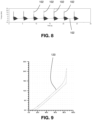
- FIG 8 is a graph illustrating the output torque (curve 100) from the decoupler 20, during simulated operation of an engine.
- curve 100 the output torque
- FIG. 8 The spikes in the torque in torque curve 100 are instants where an input torque 60 Nm was transmitted to the decoupler 20 by a belt.
- the output torque did not exceed 22 Nm.
- An example of such a situation is during start up of the vehicle in which the engine 10 sits.
- the decoupler 20 is in the first state (such as is shown in Figure 7A ).
- the decoupler input member (the pulley 24) is accelerated at a startup acceleration that is beyond the threshold acceleration, but for a period of time that is less than the selected period of time.
- the decoupler input member is accelerated at the startup acceleration, thereby preventing the decoupler 20 from transmitting all of the associated torque to the alternator shaft.
- This reduces the amount of stress is incurred by the components of the decoupler 20 itself including the wrap spring clutch 32, the carrier 30, the isolation spring 20 and the shaft adapter 22, as well as the components of the driven accessory.
- Figure 9 shows the torque-displacement curve 120 for the decoupler 20, when the torque at any instant is less than the threshold acceleration. As can be seen, there is no slippage that occurs - the torque-displacement curve is similar to that of other decoupling devices.
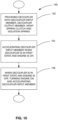
- Figure 10 illustrates a method 150 of controlling torque to an accessory (e.g. the alternator 16a) in an accessory drive on an engine (e.g. engine 10).
- the method includes a step 152 of providing a decoupler (such as the decoupler 20) including a decoupler input member (e.g. the pulley 24) and a decoupler output member (e.g. the shaft adapter 22).
- a decoupler such as the decoupler 20
- the decoupler further includes a wrap spring clutch (e.g. wrap spring clutch 32) and an isolation spring (e.g. isolation spring 28) that act in series in a torque path between the decoupler input member and the decoupler output member.
- the wrap spring clutch has a radially inner surface and a radially outer surface. One of the radially inner and outer surfaces engages the clutch engagement surface. A volume of lubricant is provided, and, in a first state of the decoupler, is positioned between said one of the radially inner and outer surfaces and the clutch engagement surface to lubricate the wrap spring clutch and the clutch engagement surface.
- Step 154 includes, while the decoupler is in the first state and the engine is on, accelerating the decoupler input member at an acceleration that is beyond a threshold acceleration, during which the volume of lubricant generates slippage between said one of the radially inner and outer surfaces and the clutch engagement surface for a period of time that is greater than a selected period of time, wherein, after the first period of time, said one of the radially inner and outer surfaces engages the clutch engagement surface without slippage.
- Step 156 includes, while the decoupler is in the first state and the engine is off, turning the engine on and accelerating the decoupler input member at a startup acceleration that is beyond the threshold acceleration, but for a period of time that is less than the selected period of time, such that there is slippage throughout when the decoupler input member is accelerated at the startup acceleration.
- the wrap spring clutch 32 is formed from a wire that has an axial dimension DA that is greater than a radial dimension DR.
- DA axial dimension
- DR radial dimension
- the lubricant 70 could be other types of grease. It is theorized that a grease having a relatively low viscosity is preferred.
Landscapes
- Engineering & Computer Science (AREA)
- General Engineering & Computer Science (AREA)
- Mechanical Engineering (AREA)
- Chemical & Material Sciences (AREA)
- Combustion & Propulsion (AREA)
- Transportation (AREA)
- Mechanical Operated Clutches (AREA)
- Pulleys (AREA)
Description
- The invention relates generally to rotary devices with clutches that are mounted on accessory drives for engines. In particular, the invention relates to decouplers on accessory drives for vehicular engines.
- During operation of a vehicle engine, it occurs sometimes that the crankshaft applies high torque to the accessory drive belt, which in turn applies this torque to the shafts of the accessories driven thereby. During some events the torque is very high, but relatively short-lived. It would be advantageous to provide a decoupling device for use on the accessory drive system that prevents such high torque inputs from reaching the accessories. Further relevant prior art is described in
US 2006/144664 A1 ,US 9 441 677 B2 US 7 153 227 B2 . - In particular, the present invention provides a decoupler having the features defined in claim 1. Further it is provided a method for controlling torque to an accessories in an accessory drive on an engine. The method has the features defined in
claim 5. Further preferred embodiments are defined in the dependent claims. - Other technical advantages may become readily apparent to one of ordinary skill in the art after review of the following figures and description.
- For a better understanding of the embodiment(s) described herein and to show more clearly how the embodiment(s) may be carried into effect, reference will now be made, by way of example only, to the accompanying drawings in which:
-
Figure 1 is an elevation view of an engine with a decoupler in accordance with an embodiment of the present invention. -
Figure 2 is a perspective exploded view of the decoupler shown inFigure 1 . -
Figure 3 is a sectional view of the decoupler shown inFigure 1 . -
Figure 4 is a perspective view of some components of the decoupler shown inFigure 1 . -
Figure 5 is a sectional view of the decoupler shown inFigure 1 , during high acceleration of a decoupler input member of the decoupler output member. -
Figure 6 is a magnified view of a portion of the decoupler shown inFigure 5 . -
Figures 7A, 7B, and 7C are highly magnified views of an interface between a pulley and a wrap spring clutch of the decoupler shown inFigure 1 during different levels of acceleration of the pulley relative to the wrap spring clutch. -
Figure 8 is a graph illustrating torque output from the decoupler shown inFigure 1 on a test machine simulating torque spikes providing high acceleration of the pulley. -
Figure 9 is a graph illustrating torque output based on angle of the pulley relative to the shaft adapter for the decoupler shown inFigure 1 , for lower torques applied to the decoupler. -
Figure 10 is a flow diagram illustrating a method of controlling torque to an accessory in an accessory drive on an engine, using a decoupler such as the decoupler shown inFigure 1 . - Unless otherwise specifically noted, articles depicted in the drawings are not necessarily drawn to scale.
- For simplicity and clarity of illustration, where considered appropriate, reference numerals may be repeated among the Figures to indicate corresponding or analogous elements. In addition, numerous specific details are set forth in order to provide a thorough understanding of the embodiment or embodiments described herein. However, it will be understood by those of ordinary skill in the art that the embodiments described herein may be practiced without these specific details. In other instances, well-known methods, procedures and components have not been described in detail so as not to obscure the embodiments described herein. The present invention should in no way be limited to the exemplary implementations and techniques illustrated in the drawings and described below.
- Various terms used throughout the present description may be read and understood as follows, unless the context indicates otherwise: "or" as used throughout is inclusive, as though written "and/or"; singular articles and pronouns as used throughout include their plural forms, and vice versa; similarly, gendered pronouns include their counterpart pronouns so that pronouns should not be understood as limiting anything described herein to use, implementation, performance, etc. by a single gender; "exemplary" should be understood as "illustrative" or "exemplifying" and not necessarily as "preferred" over other embodiments. Further definitions for terms may be set out herein; these may apply to prior and subsequent instances of those terms, as will be understood from a reading of the present description. It will also be noted that the use of the term "a" will be understood to denote "at least one" in all instances unless explicitly stated otherwise or unless it would be understood to be obvious that it must mean "one".
- Modifications, additions, or omissions may be made to the systems, apparatuses, and methods described herein without departing from the scope of the invention as in the appended claims. For example, the components of the systems and apparatuses may be integrated or separated. Moreover, the operations of the systems and apparatuses disclosed herein may be performed by more, fewer, or other components and the methods described may include more, fewer, or other steps. Additionally, steps may be performed in any suitable order. As used in this document, "each" refers to each member of a set or each member of a subset of a set.
- Reference is made to
Figure 1 , which shows anengine 10 for a vehicle. Theengine 10 includes acrankshaft 12 which drives an endless drive element, which may be, for example, abelt 14. Via thebelt 14, theengine 10 drives a plurality of accessories 16 (shown in dashed outlines), such as an alternator and an air conditioning compressor. Eachaccessory 16 includes anaccessory shaft 15 with apulley 13 thereon, which is driven by thebelt 14. Additionally, shown in the present embodiment is an idler pulley shown at 17a on anidler shaft 17b, and atensioner pulley 19a rotatably mounted on atensioner arm 19b, which form part of atensioner 19. The functions of theidler pulley 17a and thetensioner 19 are well known to one of skill in the art. - A
decoupler 20 may be provided instead of a pulley, between thebelt 14 and theaccessory shaft 15 of any one or more of the belt drivenaccessories 16. InFigure 1 , there is adecoupler 20 provided on theaccessory shaft 15 of the alternator (shown at 16a). The decoupler 20 transfers torque between thebelt 14 and theaccessory shaft 15 but automatically decouples theaccessory shaft 15 from thebelt 14 when thebelt 14 decelerates relative to theaccessory shaft 15. Additionally, thedecoupler 20 allows the speed of thebelt 14 to oscillate relative to theaccessory shaft 15. Oscillations in the speed of thebelt 14 are the result of oscillations in the speed of thecrankshaft 12, which is inherent to internal combustion piston engines. These oscillations are isolated from theaccessory shaft 15 by thedecoupler 20, and as a result, the stresses that would otherwise be incurred by theaccessory shaft 15 and theaccessory 16 are reduced. - Reference is made to
Figure 2 , which shows an exploded view of thedecoupler 20, andFigure 3 , which shows a sectional view of thedecoupler 20. Thedecoupler 20 includes ashaft adapter 22, apulley 24, anisolation spring 28, and awrap spring clutch 32. In the example shown inFigures 2 and3 , thedecoupler 20 further includes optional elements including abearing 26, abushing 27, asleeve 29, acarrier 30, anend cap 34 and athrust plate 35. - The
shaft adapter 22 is adapted to mount to theaccessory shaft 15 in any suitable way. For example, theshaft adapter 22 may have a shaft-mounting aperture 36 therethrough that defines a rotational axis A for thedecoupler 20. Theshaft mounting aperture 36 may be configured to snugly receive the end of theaccessory shaft 15. The shaft inFigure 3 is shown only partially inserted into the shaft-mounting aperture 36. A shaft-mounting fastener (not shown) may be inserted through a distal end 38 of theaperture 36 to fixedly mount theshaft adapter 22 to theaccessory shaft 15 so that the two co-rotate together about the axis A. - The
pulley 24 is rotatably coupled to theshaft adapter 22. Thepulley 24 has an outer surface which includes abelt engagement surface 40 that is configured to engage the belt 14 (Figure 1 ). Thebelt 14 may thus be a multiple-V belt. - The
pulley 24 further includes aninner surface 43. Thebearing 26 and thebushing 27 engage theinner surface 43 of thepulley 24 and rotatably support thepulley 24 on theshaft adapter 22. Thebearing 26 may be any suitable type of bearing, such as a sealed ball bearing. - The
isolation spring 28 is provided to accommodate oscillations in the speed of thebelt 14 relative to theaccessory shaft 15. Theisolation spring 28 is a helical torsion spring that has a first end 49 (Figure 2 ) that is held in anannular slot 50 and that abuts a radial wall (not shown) in theshaft adapter 22 for torque transfer therewith. Theisolation spring 28 has asecond end 52 that is positioned in thecarrier 30 to transfer torque with an end of the wrap spring clutch, as described further below. Theisolation spring 28 further includes a plurality ofcoils 58 between the first and second ends 49 and 52. An example of a suitable engagement between theisolation spring 28, theshaft adapter 22 and thecarrier 30 is shown and described inUS Patent 7,712,592 . - The
isolation spring 28 in the embodiment shown, is an opening spring, which means that, as the torque transmitted through theisolation spring 28 increases, theisolation spring 28 opens or expands radially. - The
isolation spring 28 may be compressed axially slightly in thedecoupler 20 such that it urges thecarrier 30 axially into abutment with thethrust plate 35, which is in abutment with thebearing 26, which is itself press-fit between theshaft adapter 22 and thepulley 24. - The
wrap spring clutch 32 is a helical member that has a first end 60 (Figure 4 ), also referred to as aspring engagement end 60, that is held in thecarrier 30 for engagement with thesecond end 52 of theisolation spring 28, for torque transfer therewith. Thewrap spring clutch 32 has asecond end 64 that may be referred to as thefree end 64 that is, broadly speaking, positioned to transfer torque with theinner surface 43 of thepulley 24, and a plurality ofcoils 66 between the first and second ends 60 and 64. Thewrap spring clutch 32 has a radiallyouter surface 67, which is an outer surface of the plurality ofcoils 66, and a radiallyinner surface 69, which is an inner surface of the plurality ofcoils 66. - As is known in the art of engine manufacture, the wrap spring clutch 32 permits the
pulley 24 to drive the accessory shaft during rotation of thepulley 24 in a drive direction, while permitting the accessory shaft to overrun thepulley 24 in the drive direction (e.g. during shut down of the engine 10). - Thus, a torque path is provided from the
pulley 24 through thewrap spring clutch 32, through theisolation spring 29 and into theshaft adapter 22. Worded more broadly, the wrap spring clutch and the isolation spring act in series in a torque path between thepulley 24 and theshaft adapter 22. Worded even more broadly, thepulley 24 may be considered to be just an example of a suitable decoupler input member, and theshaft adapter 22 may be considered to be just an example of a suitable decoupler output member. Thus, it may be said that thewrap spring clutch 32 and theisolation spring 28 act in series in a torque path between the decoupler input member and the decoupler output member. - The
isolation spring 28 is radially spaced from thewrap spring clutch 32 by thesleeve 57. Thesleeve 57 is, in the embodiment shown, a polymeric member having a hollow cylindrical shape with an axial slot 68 therethrough, so as to permit thesleeve 57 to expand and contract as needed. Alternatively however, thesleeve 57 could have any other suitable shape, such as a shape formed by a helically coiled wire. Thesleeve 57 acts as a torque limiter by limiting the amount of room available for radial expansion of the isolation spring 28 (in embodiments wherein theisolation spring 28 is an opening spring). Thus when a torque is provided by thepulley 24 that exceeds a selected limit, theisolation spring 28 expands and engages thesleeve 57. Theisolation spring 28 then expands further, causing expansion of thesleeve 57 until thesleeve 57 engages the radially inner 69 of thewrap spring clutch 32, which constrains thesleeve 57 from further expansion. Thesleeve 57 then constrains theisolation spring 28 against further radial expansion. Thesleeve 57 may be made from any suitable material such as a polymeric material, such as a nylon, for example. An example of asuitable sleeve 57 is shown and described inUS Patent 7,766,774 . - When the
decoupler 20 is assembled, one of the radially inner andouter surfaces pulley 24 in an interference fit. In the embodiment shown, the radiallyouter surface 67 of the wrap spring clutch engages theinner surface 43 of the pulley in the aforementioned interference fit. The inner surface of the pulley may thus be referred to as a clutch engagement surface. In other embodiments it is possible for thepulley 24 to have a radially outer surface that is the clutch engagement surface and which is engaged by the radiallyinner surface 69 of thewrap spring clutch 32 in an interference fit. - When a torque is applied from the
belt 14 to thepulley 24 to drive thepulley 24 at a speed that is faster than that of theaccessory shaft 15, friction between theinner surface 43 of thepulley 24 and thefree end 64 of thewrap spring clutch 32 drives thefree end 64 through at least some angle in a first rotational direction about the axis A, relative to thefirst end 60 of thewrap spring clutch 32. The relative movement between thefree end 64 driven by thepulley 24 relative to thefirst end 60 causes the wrap spring clutch to expand radially, which further strengthens the grip between the radiallyouter surface 67 of thewrap spring clutch 32 and theinner surface 43 of thepulley 24. As a result, thefirst end 60 of thewrap spring clutch 32 transmits the torque from thepulley 24 to theisolation spring 28, which in turn transmits the torque to theshaft adapter 22. As a result, theshaft adapter 22 is brought up to the speed of thepulley 24. Thus, when thepulley 24 rotates faster than theshaft adapter 22 in the first rotational direction, thewrap spring clutch 32 operatively connects thepulley 24 to the carrier and therefore to theshaft adapter 22. - A volume of lubricant shown at 70 is provided in an
interior space 72 in thedecoupler 20. Thelubricant 70 may be any suitable lubricant such as Krytox™. In a first state of the decoupler, some of the lubricant is positioned between the radiallyouter surface 67 of thewrap spring clutch 32 and the clutch engagement surface to lubricate the wrap spring clutch and the clutch engagement surface. For example, when the vehicle is turned off, there will belubricant 70 between thewrap spring clutch 32 and the clutch engagement surface. - At various times during operation of the engine 10 a torque will be applied to the decoupler input member which causes an acceleration of the decoupler input member relative to the decoupler output member. The torque is transmitted through the
wrap spring clutch 32 and theisolation spring 28 to the decoupler output member (i.e. theshaft adapter 22 in the present embodiment). However, if the acceleration is beyond a threshold acceleration, thelubricant 70 generates slippage between thewrap spring clutch 32 and the clutch engagement surface for some time. In the embodiment shown, this slippage occurs as a result of the following actions, with reference toFigures 5 and 6 . As torque is applied to thepulley 24, the torque is transferred to thewrap spring clutch 32 and from thewrap spring clutch 32 into thesecond end 52 of theisolation spring 28. The torque passes through theisolation spring 28 to thefirst end 49 thereof, and into theshaft adapter 22. During the torque transfer through theisolation spring 28, theisolation spring 28 expands radially. - It is to be noted that the
first end 49 of theisolation spring 28 is positioned axially adjacent thefree end 64 of thewrap spring clutch 32. It will be understood that thefirst end 49 of theisolation spring 28 is not just the helical tip at one end of theisolation spring 28 but is intended to mean just that tip in some embodiments, or theendmost coil 58 of theisolation spring 28 in some embodiments, or the endmostfew coils 58 of theisolation spring 28 in some other embodiments. In the embodiment shown, thefirst end 49 of the isolation spring includes all of the coils that are closer to the helical tip that engages the aforementioned radial wall of theshaft adapter 22, and thesecond end 52 includes the other coils of theisolation spring 28, which are closer to the opposing helical tip that is positioned in thecarrier 30. - As the
isolation spring 28 expands, it drives thesleeve 57 to pinch thecoils 66 of thewrap spring clutch 32. In particular, thecoils 58 of theisolation spring 28 closest to thefirst end 49 cause pinching of thecoils 66 of thewrap spring clutch 32 closest to thefree end 64. During torque transfer through thedecoupler 20, there is relative movement between thefree end 64 and thespring engagement end 60 of thewrap spring clutch 32, and further relative movement between thesecond end 52 and thefirst end 49 of theisolation spring 28. From the perspective of thecarrier 30, it can be said that there is relative movement of thefree end 64 of thewrap spring clutch 32 relative to thecarrier 30 in a first rotational direction (shown at D1 inFigure 4 ), and there is relative movement of thefirst end 49 of theisolation spring 28 relative to thecarrier 30 in a second rotational direction D2. D1 and D2 are opposite to one another. It can be seen that the greatest amount of relative movement therefore occurs between thefirst end 49 of theisolation spring 28 and thefree end 64 of the wrap spring clutch. - During acceleration of the decoupler input member relative to the decoupler output member that is greater than the threshold acceleration, radial movement of the
first end 49 of theisolation spring 28 drives radial movement of thesleeve 57 so as to frictionally engage thefree end 64 of thewrap spring clutch 32 so as to cause resistance to rotational movement of thefree end 64 of thewrap spring clutch 32 in the first rotational direction D1 relative to thecarrier 30. - Furthermore, the
isolation spring 28 thus incurs a first force F1 into it from thespring engagement end 60 of thewrap spring clutch 32 and a second force F2 into it from the radial wall (not shown) of the shaft adapter 22 (which is a reaction force resulting from the torque transfer from theisolation spring 28 into the shaft adapter 22). These first and second forces F1 and F2 are shown inFigure 4 . The positions of the first and second ends 49 and 52 of theisolation spring 28 determine the positions of these first and second forces F1 and F2. In the present embodiment, these forces F1 and F2 combine to cause theisolation spring 28 to be canted slightly.Figure 5 shows theisolation spring 28 with its axis AS at a slight angle to the axis A of theshaft adapter 22. Optionally, the first and second ends 49 and 52 can be arranged such that theisolation spring 28 is canted in a direction to further pinch thefree end 64 of thewrap spring clutch 32, thereby further inhibiting thefree end 64 from being dragged by thepulley 24 in an opening direction. - Inhibiting the
free end 64 of the wrap spring clutch 32 from moving in the opening direction restricts the radially directed force of engagement that exists between thewrap spring clutch 32 and thepulley 24, which in turn restricts the amount of torque that can be transferred between thewrap spring clutch 32 and thepulley 24. - If the acceleration of the
pulley 24 is relatively low, then the force of engagement between thewrap spring clutch 32 and thepulley 24 is sufficient that there is no slippage between the two, and so torque transfer takes place without slip (or essentially without slip). - It will be understood that the amount of torque transfer that can take place is dependent on both the radial force of engagement and the coefficient of friction between the
wrap spring clutch 32 and thepulley 24. The coefficient of friction is dependent on whether or not there is effectively anylubricant 70 between them, (or more accurately, howmuch lubricant 70 is between them).Figures 7A, 7B and 7C illustrate, at a highly magnified level, what is taking place in this regard.Figure 7A represents a situation where thedecoupler 20 is in the first state, which is when there is no torque applied to thepulley 24 relative to the rest of the decoupler 20 (e.g. when theengine 10 is off). The interface between thewrap spring clutch 32 and thepulley 24 is shown inFigures 7A, 7B, and 7C . As can be seen, a relatively large layer oflubricant 70 is present between thewrap spring clutch 32 and thepulley 24. - If the acceleration of the
pulley 24 is beyond a threshold acceleration, some torque is transmitted to thewrap spring clutch 32 causing thewrap spring clutch 32 to expand radially into stronger engagement with thepulley 24, however the presence of thelubricant 70 initially provides a low coefficient of friction between thewrap spring clutch 32 and thepulley 24, which permits the movement of theisolation spring 28 and thesleeve 57 to inhibit movement of thefree end 64 of the wrap spring clutch, thereby causing slippage between thewrap spring clutch 32 and thepulley 24, and in turn limiting the amount of torque that is transferred through thedecoupler 20. This event is represented inFigure 7B , wherein thewrap spring clutch 32 has expanded by some amount to squeeze out some of thelubricant 70, but wherein there is still enough of a layer oflubricant 70 therebetween, to generate slippage, limiting torque transfer. After a certain period of time, more of thelubricant 70 will be squeezed out of the space between thewrap spring clutch 32 and thepulley 24, such that the radiallyouter surface 67 of thewrap spring clutch 32 engages the clutch engagement surface without slippage. The amount of time during which there is slippage will depend on such factors as the amount of interference there is between thewrap spring clutch 32 and thepulley 24, and the properties of the lubricant (e.g. the viscosity thereof). - The amount of interference and the lubricant are selected such that, when the
decoupler 20 is in the first state and the decoupler input member is accelerated at an acceleration that is beyond the threshold acceleration, thelubricant 70 generates slippage between thewrap spring clutch 32 and the clutch engagement surface for a selected period of time. After the selected period of time, thewrap spring clutch 32 engages the clutch engagement surface without slippage. - The selected period of time is selected such that, when the
engine 10 is turned on, the decoupler input member is accelerated at a startup acceleration that is beyond the threshold acceleration, but for a period of time that is less than the selected period of time, such that there is slippage between thewrap spring clutch 32 and the clutch engagement surface throughout when the decoupler input member is accelerated at the startup acceleration. - However, during operation of the vehicle, such as, during cruising at a constant speed and when the
decoupler 20 is in the first state (such that there is lubricant in the space between the wrap spring clutch and the pulley 24), when the torque applied to thedecoupler 20 is high (such that the acceleration of the decoupler input member is greater than the threshold acceleration) and is sustained for a long period of time, it can occur that theengine 10 can undergo a high torque load for a sustained period of time. In such a situation, accelerating the decoupler input member at an acceleration that is beyond a threshold acceleration for a period of time that is greater than the selected period of time would occur. During this time, the volume of lubricant generates slippage betweenwrap spring clutch 32 and thepulley 24 for the selected period of time and then, after the first period of time, thewrap spring clutch 32 would engage thepulley 24 without slippage. In other words, during continued acceleration beyond the threshold acceleration after the first period of time, thewrap spring clutch 32 would engage thepulley 24 without slippage. -
Figure 8 is a graph illustrating the output torque (curve 100) from thedecoupler 20, during simulated operation of an engine. As a result of thedecoupler 20, large torque spikes that are short-lived can be accommodated without transmission of the large torque through thedecoupler 20 and into the accessory shaft. Such torque spikes are shown at 102. The spikes in the torque in torque curve 100 are instants where aninput torque 60 Nm was transmitted to thedecoupler 20 by a belt. As can be seen, the output torque did not exceed 22 Nm. An example of such a situation is during start up of the vehicle in which theengine 10 sits. When thevehicle 10 is off, thedecoupler 20 is in the first state (such as is shown inFigure 7A ). When theengine 10 is turned on, the decoupler input member (the pulley 24) is accelerated at a startup acceleration that is beyond the threshold acceleration, but for a period of time that is less than the selected period of time. As a result there is slippage throughout when the decoupler input member is accelerated at the startup acceleration, thereby preventing thedecoupler 20 from transmitting all of the associated torque to the alternator shaft. This reduces the amount of stress is incurred by the components of thedecoupler 20 itself including thewrap spring clutch 32, thecarrier 30, theisolation spring 20 and theshaft adapter 22, as well as the components of the driven accessory. -
Figure 9 shows the torque-displacement curve 120 for thedecoupler 20, when the torque at any instant is less than the threshold acceleration. As can be seen, there is no slippage that occurs - the torque-displacement curve is similar to that of other decoupling devices. -
Figure 10 illustrates amethod 150 of controlling torque to an accessory (e.g. the alternator 16a) in an accessory drive on an engine (e.g. engine 10). The method includes astep 152 of providing a decoupler (such as the decoupler 20) including a decoupler input member (e.g. the pulley 24) and a decoupler output member (e.g. the shaft adapter 22). One of the decoupler input member and the decoupler output member has a clutch engagement surface. The decoupler further includes a wrap spring clutch (e.g. wrap spring clutch 32) and an isolation spring (e.g. isolation spring 28) that act in series in a torque path between the decoupler input member and the decoupler output member. The wrap spring clutch has a radially inner surface and a radially outer surface. One of the radially inner and outer surfaces engages the clutch engagement surface. A volume of lubricant is provided, and, in a first state of the decoupler, is positioned between said one of the radially inner and outer surfaces and the clutch engagement surface to lubricate the wrap spring clutch and the clutch engagement surface. - Step 154 includes, while the decoupler is in the first state and the engine is on, accelerating the decoupler input member at an acceleration that is beyond a threshold acceleration, during which the volume of lubricant generates slippage between said one of the radially inner and outer surfaces and the clutch engagement surface for a period of time that is greater than a selected period of time, wherein, after the first period of time, said one of the radially inner and outer surfaces engages the clutch engagement surface without slippage.
- Step 156 includes, while the decoupler is in the first state and the engine is off, turning the engine on and accelerating the decoupler input member at a startup acceleration that is beyond the threshold acceleration, but for a period of time that is less than the selected period of time, such that there is slippage throughout when the decoupler input member is accelerated at the startup acceleration.
- As can be seen in
Figure 6 particularly, thewrap spring clutch 32 is formed from a wire that has an axial dimension DA that is greater than a radial dimension DR. As a result of this, there is reduced pressure against the clutch engagement surface, for a given number of coils of wire to form thewrap spring clutch 32, since the overall surface area is larger than, say, for a wrap spring clutch formed by a similar wire but whose radial dimension was less than the axial dimension. Additionally, it will be noted that the reduced radial dimension for the wire of thewrap spring clutch 32 relative to the axial dimension, provides for reduced stiffness in the radial direction, which further contributes to maintaining the slippage when slippage is induced. - While a grease such as Krytox™ has been used in some embodiments for the
lubricant 70, it will be noted that thelubricant 70 could be other types of grease. It is theorized that a grease having a relatively low viscosity is preferred. - Persons skilled in the art will appreciate that there are yet more alternative implementations and modifications possible, and that the above examples are only illustrations of one or more implementations. The scope, therefore, is only to be limited by the claims appended hereto and any amendments made thereto.
Claims (5)
- A decoupler (20) for an accessory drive for an engine (10), comprising:a decoupler input member (24) and a decoupler output member (22), wherein one of the decoupler input member (24) and the decoupler output member (22) has a clutch engagement surface (43);a wrap spring clutch (32) and an isolation spring (28) that act in series in a torque path between the decoupler input member (24) and the decoupler output member (22), wherein the wherein the wrap spring clutch (32) has a radially inner surface (69) and a radially outer surface (67), wherein one of the radially inner and outer surfaces (69, 67) engages the clutch engagement surface (43) in an interference fit with the clutch engagement surface; anda volume (70) of lubricant that, in a first state of the decoupler (20), is positioned between said one of the radially inner and outer surfaces (69, 67) and the clutch engagement surface (43) to lubricate the wrap spring clutch (32) and the clutch engagement surface (43),wherein, the amount of interference and the lubricant are selected such that, when the decoupler is in the first state and the decoupler input member is accelerated at an acceleration that is beyond a threshold acceleration, the volume of lubricant generates slippage between said one of the radially inner and outer surfaces (69, 67) and the clutch engagement surface (43) for a selected period of time,wherein, after the selected period of time, said one of the radially inner and outer surfaces (69, 67) engages the clutch engagement surface (43) without slippage;wherein, when the decoupler is connected to an engine, the decoupler is in the first state when the engine is off, and wherein, when the engine is turned on, the decoupler input member is accelerated at a startup acceleration that is beyond the threshold acceleration, but for a period of time that is less than the selected period of time, such that there is slippage throughout when the decoupler input member is accelerated at the startup acceleration, wherein the isolation spring (28) is a helical torsion spring that is radially spaced from the wrap spring clutch (32) by a sleeve (57), wherein the wrap spring clutch (32) has a spring engagement end (60) that is held in a carrier (30), and a free end (64), wherein the free end (64) is positioned to transfer torque with the clutch engagement surface during acceleration of the decoupler input member (24) relative to the decoupler output member,and wherein the isolation spring has a first end and a second end (49, 52), wherein the second end (52) is positioned in the carrier (30) to transfer torque with the spring engagement end (60) of the wrap spring clutch (32), and the first end (49) is positioned to transfer torque with the other of the decoupler input member (24) and the decoupler output member (22),wherein the first end (49) of the isolation spring (28) is positioned axially adjacent the free end (64) of the wrap spring clutch (32),wherein, during acceleration of the decoupler input member (24) relative to the decoupler output member (22), there is relative movement of the free end (64) of the wrap spring clutch (32) relative to the carrier in a first rotational direction (91), and there is relative movement of the second end (52) of the isolation spring (28) relative to the carrier in a second rotational direction (D2),and wherein during acceleration of the decoupler input member (24) relative to the decoupler output member (22) that is greater than the threshold acceleration, radial movement of the first end (49) of the isolation spring drives radial movement of the sleeve (57) so as to frictionally engage the free end of the wrap spring clutch so as to cause resistance to rotational movement of the free end of the wrap spring clutch in the first rotational direction relative to the carrier, wherein the wrap spring clutch (32) is made from a wire having cross-sectional shape with a radial dimension and an axial dimension that is greater than the radial dimension.
- A decoupler as claimed in claim 1, wherein said one of the radially inner and outer surfaces (69, 67) is the radially outer surface (67), and the clutch engagement surface (43) is a radially inner surface of the decoupler input member.
- A decoupler as claimed in claim 2, wherein the decoupler input member is a pulley and the decoupler output member is a shaft adapter that is configured for mounting to an accessory for the engine.
- A decoupler as claimed in claim 1, wherein the decoupler input member is a pulley and the decoupler output member is a shaft adapter that is configured for mounting to an alternator for the engine.
- A method of controlling torque to an accessory (16) in an accessory drive on an engine (10), comprising:a) providing a decoupler (20) according to any of claims 1-4 including a decoupler input member (22) and a decoupler output member (24), wherein one of the decoupler input member (22) and the decoupler output member (24) has a clutch engagement surface (43), and further including a wrap spring clutch (32) and an isolation spring (28) that act in series in a torque path between the decoupler input member (22) and the decoupler output member (24), wherein the wrap spring clutch (32) has a radially inner surface (69) and a radially outer surface (67), wherein one of the radially inner and outer surfaces (69, 67) engages the clutch engagement surface (43), and further including a volume (70) of lubricant that, in a first state of the decoupler (20), is positioned between said one of the radially inner and outer surfaces (69, 67) and the clutch engagement surface (43) to lubricate the wrap spring clutch and the clutch engagement surface;b) while the decoupler (20) is in the first state and the engine (10) is on, accelerating the decoupler input member (22) at an acceleration that is beyond a threshold acceleration, during which the volume of lubricant generates slippage between said one of the radially inner and outer surfaces (69, 67) and the clutch engagement surface (43) for a selected period of time, and then during continued acceleration beyond the threshold acceleration after the first period of time, said one of the radially inner and outer surfaces engages the clutch engagement surface (43) without slippage; andc) while the decoupler (20) is in the first state and the engine is off, turning the engine on and accelerating the decoupler input member (22) at a startup acceleration that is beyond the threshold acceleration, but for a period of time that is less than the selected period of time, such that there is slippage throughout when the decoupler input member (22) is accelerated at the startup acceleration.
Applications Claiming Priority (3)
| Application Number | Priority Date | Filing Date | Title |
|---|---|---|---|
| US201962823662P | 2019-03-26 | 2019-03-26 | |
| US201962930255P | 2019-11-04 | 2019-11-04 | |
| PCT/CA2020/050398 WO2020191495A1 (en) | 2019-03-26 | 2020-03-26 | Rotary device with clutch with time-based slip and method of providing time-based slip for a rotary device |
Publications (3)
| Publication Number | Publication Date |
|---|---|
| EP3948002A1 EP3948002A1 (en) | 2022-02-09 |
| EP3948002A4 EP3948002A4 (en) | 2022-12-21 |
| EP3948002B1 true EP3948002B1 (en) | 2024-04-03 |
Family
ID=72608405
Family Applications (1)
| Application Number | Title | Priority Date | Filing Date |
|---|---|---|---|
| EP20777522.2A Active EP3948002B1 (en) | 2019-03-26 | 2020-03-26 | Rotary device with clutch with time-based slip and method of providing time-based slip for a rotary device |
Country Status (4)
| Country | Link |
|---|---|
| US (1) | US12005779B2 (en) |
| EP (1) | EP3948002B1 (en) |
| CN (1) | CN113474570B (en) |
| WO (1) | WO2020191495A1 (en) |
Families Citing this family (1)
| Publication number | Priority date | Publication date | Assignee | Title |
|---|---|---|---|---|
| IT202000030395A1 (en) * | 2020-12-10 | 2022-06-10 | Dayco Europe Srl | IMPROVED FILTER PULLEY |
Family Cites Families (51)
| Publication number | Priority date | Publication date | Assignee | Title |
|---|---|---|---|---|
| US2899193A (en) | 1959-08-11 | Low gradient spring motor | ||
| US2559400A (en) | 1945-01-08 | 1951-07-03 | Eaton Mfg Co | Spring testing machine |
| US2761547A (en) | 1954-10-22 | 1956-09-04 | Fortuna Werke Spezialmaschinen | Rollers |
| US3047280A (en) | 1959-02-25 | 1962-07-31 | Ametek Inc | Spring motor |
| US3602205A (en) | 1969-05-13 | 1971-08-31 | Eaton Yale & Towne | Dual beam valve spring |
| US3618730A (en) | 1969-12-12 | 1971-11-09 | Vari Typer Corp | Torque-limiting clutch |
| US4750087A (en) | 1984-03-26 | 1988-06-07 | The Boeing Company | Ventilated instrument panel support rail |
| CN85102855B (en) | 1985-04-01 | 1987-09-23 | 曹培生 | Nonlinear electromagnetic oscillation device |
| US4750871A (en) | 1987-03-10 | 1988-06-14 | Mechanical Technology Incorporated | Stabilizing means for free piston-type linear resonant reciprocating machines |
| US5139463A (en) | 1991-06-05 | 1992-08-18 | Litens Automotive Partnership | Serpentine drive with coil spring alternator connection |
| DE4426666A1 (en) | 1994-07-28 | 1996-02-01 | Schaeffler Waelzlager Kg | Device for damping spring vibrations |
| JPH09117721A (en) | 1994-09-28 | 1997-05-06 | Seiko Instr Inc | Vibration module |
| GB9420741D0 (en) | 1994-10-14 | 1994-11-30 | Litens Automotive Inc | Crankshaft decoupler |
| US5722909A (en) * | 1995-09-27 | 1998-03-03 | Litens Automotive Partnership | Series type decoupling device |
| US5749449A (en) | 1996-12-16 | 1998-05-12 | Sikorsky Aircraft Corporation | Coil spring for overrunning spring clutches |
| ATE248300T1 (en) | 1997-05-07 | 2003-09-15 | Litens Automotive Inc | BELT DRIVE SYSTEM WITH GENERATOR CONNECTION ONE-WAY CLUTCH |
| US6047811A (en) | 1997-08-21 | 2000-04-11 | David R. Zittel | Method and vibratory conveyor |
| US6161512A (en) | 1998-09-17 | 2000-12-19 | Morse Tec Europe S.P.A. | Sprocket system with internal torsional damper |
| US7191880B2 (en) | 2000-05-31 | 2007-03-20 | Ntn Corporation | Over-running clutch pulley with increased surface microhardness |
| US6394248B1 (en) | 2000-05-31 | 2002-05-28 | Ntn Corporation | Compression spring complaint one-way over-running clutch pulley |
| JP2002227973A (en) | 2001-02-05 | 2002-08-14 | Ntn Corp | Spring clutch |
| US6710489B1 (en) | 2001-08-30 | 2004-03-23 | Indigo Energy, Inc. | Axially free flywheel system |
| JP2003278790A (en) | 2002-03-20 | 2003-10-02 | Suncall Corp | Friction type rotational movement transmitting device |
| US7153227B2 (en) | 2002-04-18 | 2006-12-26 | Litens Automotive | Isolator for alternator pulley |
| DE60321409D1 (en) | 2002-07-26 | 2008-07-10 | Litens Automotive | Cutting disc for continuous alternator with bare wire spring and grease lubrication |
| CA2759773C (en) | 2002-11-22 | 2013-05-28 | Litens Automotive | Flexible coupling with misalignment compensation |
| DE602004026540D1 (en) | 2003-02-04 | 2010-05-27 | Litens Automotive | KURBELWELLE MOMENT MODULATOR |
| EP2273144B1 (en) | 2003-09-22 | 2012-11-28 | Litens Automotive Partnership | Crankshaft decoupler |
| WO2005057037A1 (en) | 2003-12-09 | 2005-06-23 | Litens Automotive Partnership | Spring travel limitor for overrunning decoupler |
| JP4549098B2 (en) | 2004-05-10 | 2010-09-22 | Ntn株式会社 | Spring clutch |
| US7318776B2 (en) | 2004-05-24 | 2008-01-15 | Ntn Corporation | Torque limiter |
| FR2878305B1 (en) | 2004-11-24 | 2008-05-30 | Hutchinson Sa | POWER TRANSMISSION DEVICE PULLEY, SEPARATE ALTERNOMETER STARTER EQUIPPED WITH SUCH PULLEY AND THERMAL MOTOR DRIVE SYSTEM |
| KR101266602B1 (en) | 2005-02-03 | 2013-05-22 | 리텐스 오토모티브 파트너쉽 | Torque limited decoupler |
| CN101208534A (en) | 2005-07-05 | 2008-06-25 | 利滕斯汽车合伙公司 | Overspeed decoupler with locking mechanism |
| FR2891039B1 (en) | 2005-09-19 | 2009-05-22 | Hutchinson Sa | POWER TRANSMISSION PULLEY |
| JP5008928B2 (en) | 2005-10-31 | 2012-08-22 | 三ツ星ベルト株式会社 | Pulley structure |
| US7878315B2 (en) | 2006-04-14 | 2011-02-01 | Ntn Corporation | Spring clutch |
| EP2010792B1 (en) | 2006-04-26 | 2015-03-25 | Litens Automotive Partnership | One-way isolator for high torque devices |
| DE112007002873A5 (en) | 2006-12-11 | 2009-10-08 | Luk Lamellen Und Kupplungsbau Beteiligungs Kg | Decoupler assembly |
| CN102203450B (en) | 2008-10-27 | 2016-08-03 | 利滕斯汽车合伙公司 | Override decoupler with torque limiter |
| US8485331B2 (en) * | 2008-11-17 | 2013-07-16 | Litens Automotive Partnership | Driven accessory with low-power clutch for activating or de-activating same |
| CN102985716B (en) * | 2010-06-25 | 2016-08-10 | 利滕斯汽车合伙公司 | Over-speed decoupler |
| CN102959262B (en) * | 2010-06-25 | 2016-01-20 | 利滕斯汽车合伙公司 | Isolation pulleys with overrunning and vibration damping capabilities |
| US8813928B2 (en) * | 2011-10-14 | 2014-08-26 | The Gates Corporation | Alternator isolating decoupler |
| CN104520601B (en) * | 2012-08-07 | 2017-09-29 | 利滕斯汽车合伙公司 | Separator carrier with balanced force |
| US9140319B2 (en) | 2012-11-20 | 2015-09-22 | Litens Automotive Partnership | Decoupler with concentric clutching members |
| CN105793592B (en) * | 2013-08-19 | 2018-09-04 | 利滕斯汽车合伙公司 | The clutch engagement surface with selected surface finish structure of separator |
| US9033832B1 (en) * | 2014-01-23 | 2015-05-19 | Gates Corporation | Isolating decoupler |
| US9206892B2 (en) * | 2014-04-08 | 2015-12-08 | Gates Corporation | Isolating decoupler |
| US10024415B2 (en) * | 2015-11-02 | 2018-07-17 | Gates Corporation | Isolating decoupler |
| US10520039B2 (en) * | 2017-08-28 | 2019-12-31 | Gates Corporation | Isolating decoupler |
-
2020
- 2020-03-26 US US17/593,289 patent/US12005779B2/en active Active
- 2020-03-26 WO PCT/CA2020/050398 patent/WO2020191495A1/en not_active Ceased
- 2020-03-26 CN CN202080016765.8A patent/CN113474570B/en active Active
- 2020-03-26 EP EP20777522.2A patent/EP3948002B1/en active Active
Also Published As
| Publication number | Publication date |
|---|---|
| WO2020191495A1 (en) | 2020-10-01 |
| EP3948002A1 (en) | 2022-02-09 |
| US20220194225A1 (en) | 2022-06-23 |
| CN113474570A (en) | 2021-10-01 |
| EP3948002A4 (en) | 2022-12-21 |
| CN113474570B (en) | 2024-08-30 |
| US12005779B2 (en) | 2024-06-11 |
Similar Documents
| Publication | Publication Date | Title |
|---|---|---|
| CN102203450B (en) | Override decoupler with torque limiter | |
| US7070033B2 (en) | Flexible coupling with misalignment compensation | |
| KR101266602B1 (en) | Torque limited decoupler | |
| JP5945630B2 (en) | Isolator / Decoupler | |
| EP1692409B1 (en) | Spring travel limitor for overrunning decoupler | |
| EP2715171B1 (en) | Isolator decoupler | |
| EP2823192B1 (en) | Isolator decler with torque limiter | |
| CN107532653B (en) | Isolating disconnector | |
| KR20050039832A (en) | Overrunning alternator decoupler pulley with bare wire spring and grease lubrication | |
| US20100116617A1 (en) | Isolator with one-way clutch | |
| JP6906514B2 (en) | Isolating decoupler | |
| CN103221704A (en) | Decoupler assembly having limited overrunning capability | |
| EP3948002B1 (en) | Rotary device with clutch with time-based slip and method of providing time-based slip for a rotary device | |
| JP2025506559A (en) | Decoupler with torque limiting function to protect components | |
| JP2021169831A (en) | Power transmission device | |
| CN118749047A (en) | Decoupler with torque limiting feature to protect its components |
Legal Events
| Date | Code | Title | Description |
|---|---|---|---|
| STAA | Information on the status of an ep patent application or granted ep patent |
Free format text: STATUS: THE INTERNATIONAL PUBLICATION HAS BEEN MADE |
|
| PUAI | Public reference made under article 153(3) epc to a published international application that has entered the european phase |
Free format text: ORIGINAL CODE: 0009012 |
|
| STAA | Information on the status of an ep patent application or granted ep patent |
Free format text: STATUS: REQUEST FOR EXAMINATION WAS MADE |
|
| 17P | Request for examination filed |
Effective date: 20210913 |
|
| AK | Designated contracting states |
Kind code of ref document: A1 Designated state(s): AL AT BE BG CH CY CZ DE DK EE ES FI FR GB GR HR HU IE IS IT LI LT LU LV MC MK MT NL NO PL PT RO RS SE SI SK SM TR |
|
| DAV | Request for validation of the european patent (deleted) | ||
| DAX | Request for extension of the european patent (deleted) | ||
| A4 | Supplementary search report drawn up and despatched |
Effective date: 20221118 |
|
| RIC1 | Information provided on ipc code assigned before grant |
Ipc: F16D 41/20 20060101ALI20221114BHEP Ipc: F16H 7/20 20060101ALI20221114BHEP Ipc: F16D 43/02 20060101ALI20221114BHEP Ipc: F16D 3/14 20060101ALI20221114BHEP Ipc: F16D 13/12 20060101ALI20221114BHEP Ipc: F02B 67/06 20060101ALI20221114BHEP Ipc: B60K 25/02 20060101ALI20221114BHEP Ipc: F16D 7/02 20060101AFI20221114BHEP |
|
| RIC1 | Information provided on ipc code assigned before grant |
Ipc: F16D 41/20 20060101ALI20230901BHEP Ipc: F16H 7/20 20060101ALI20230901BHEP Ipc: F16D 43/02 20060101ALI20230901BHEP Ipc: F16D 3/14 20060101ALI20230901BHEP Ipc: F16D 13/12 20060101ALI20230901BHEP Ipc: F02B 67/06 20060101ALI20230901BHEP Ipc: B60K 25/02 20060101ALI20230901BHEP Ipc: F16D 7/02 20060101AFI20230901BHEP |
|
| GRAP | Despatch of communication of intention to grant a patent |
Free format text: ORIGINAL CODE: EPIDOSNIGR1 |
|
| STAA | Information on the status of an ep patent application or granted ep patent |
Free format text: STATUS: GRANT OF PATENT IS INTENDED |
|
| INTG | Intention to grant announced |
Effective date: 20231121 |
|
| GRAS | Grant fee paid |
Free format text: ORIGINAL CODE: EPIDOSNIGR3 |
|
| GRAA | (expected) grant |
Free format text: ORIGINAL CODE: 0009210 |
|
| STAA | Information on the status of an ep patent application or granted ep patent |
Free format text: STATUS: THE PATENT HAS BEEN GRANTED |
|
| P01 | Opt-out of the competence of the unified patent court (upc) registered |
Effective date: 20240130 |
|
| AK | Designated contracting states |
Kind code of ref document: B1 Designated state(s): AL AT BE BG CH CY CZ DE DK EE ES FI FR GB GR HR HU IE IS IT LI LT LU LV MC MK MT NL NO PL PT RO RS SE SI SK SM TR |
|
| REG | Reference to a national code |
Ref country code: CH Ref legal event code: EP |
|
| REG | Reference to a national code |
Ref country code: DE Ref legal event code: R096 Ref document number: 602020028421 Country of ref document: DE |
|
| REG | Reference to a national code |
Ref country code: IE Ref legal event code: FG4D |
|
| REG | Reference to a national code |
Ref country code: LT Ref legal event code: MG9D |
|
| REG | Reference to a national code |
Ref country code: NL Ref legal event code: MP Effective date: 20240403 |
|
| REG | Reference to a national code |
Ref country code: AT Ref legal event code: MK05 Ref document number: 1672627 Country of ref document: AT Kind code of ref document: T Effective date: 20240403 |
|
| PG25 | Lapsed in a contracting state [announced via postgrant information from national office to epo] |
Ref country code: NL Free format text: LAPSE BECAUSE OF FAILURE TO SUBMIT A TRANSLATION OF THE DESCRIPTION OR TO PAY THE FEE WITHIN THE PRESCRIBED TIME-LIMIT Effective date: 20240403 |
|
| PG25 | Lapsed in a contracting state [announced via postgrant information from national office to epo] |
Ref country code: NL Free format text: LAPSE BECAUSE OF FAILURE TO SUBMIT A TRANSLATION OF THE DESCRIPTION OR TO PAY THE FEE WITHIN THE PRESCRIBED TIME-LIMIT Effective date: 20240403 |
|
| PG25 | Lapsed in a contracting state [announced via postgrant information from national office to epo] |
Ref country code: IS Free format text: LAPSE BECAUSE OF FAILURE TO SUBMIT A TRANSLATION OF THE DESCRIPTION OR TO PAY THE FEE WITHIN THE PRESCRIBED TIME-LIMIT Effective date: 20240803 |
|
| PG25 | Lapsed in a contracting state [announced via postgrant information from national office to epo] |
Ref country code: BG Free format text: LAPSE BECAUSE OF FAILURE TO SUBMIT A TRANSLATION OF THE DESCRIPTION OR TO PAY THE FEE WITHIN THE PRESCRIBED TIME-LIMIT Effective date: 20240403 |
|
| PG25 | Lapsed in a contracting state [announced via postgrant information from national office to epo] |
Ref country code: HR Free format text: LAPSE BECAUSE OF FAILURE TO SUBMIT A TRANSLATION OF THE DESCRIPTION OR TO PAY THE FEE WITHIN THE PRESCRIBED TIME-LIMIT Effective date: 20240403 Ref country code: FI Free format text: LAPSE BECAUSE OF FAILURE TO SUBMIT A TRANSLATION OF THE DESCRIPTION OR TO PAY THE FEE WITHIN THE PRESCRIBED TIME-LIMIT Effective date: 20240403 |
|
| PG25 | Lapsed in a contracting state [announced via postgrant information from national office to epo] |
Ref country code: GR Free format text: LAPSE BECAUSE OF FAILURE TO SUBMIT A TRANSLATION OF THE DESCRIPTION OR TO PAY THE FEE WITHIN THE PRESCRIBED TIME-LIMIT Effective date: 20240704 |
|
| PG25 | Lapsed in a contracting state [announced via postgrant information from national office to epo] |
Ref country code: PT Free format text: LAPSE BECAUSE OF FAILURE TO SUBMIT A TRANSLATION OF THE DESCRIPTION OR TO PAY THE FEE WITHIN THE PRESCRIBED TIME-LIMIT Effective date: 20240805 |
|
| PG25 | Lapsed in a contracting state [announced via postgrant information from national office to epo] |
Ref country code: ES Free format text: LAPSE BECAUSE OF FAILURE TO SUBMIT A TRANSLATION OF THE DESCRIPTION OR TO PAY THE FEE WITHIN THE PRESCRIBED TIME-LIMIT Effective date: 20240403 |
|
| PG25 | Lapsed in a contracting state [announced via postgrant information from national office to epo] |
Ref country code: CZ Free format text: LAPSE BECAUSE OF FAILURE TO SUBMIT A TRANSLATION OF THE DESCRIPTION OR TO PAY THE FEE WITHIN THE PRESCRIBED TIME-LIMIT Effective date: 20240403 |
|
| PG25 | Lapsed in a contracting state [announced via postgrant information from national office to epo] |
Ref country code: AT Free format text: LAPSE BECAUSE OF FAILURE TO SUBMIT A TRANSLATION OF THE DESCRIPTION OR TO PAY THE FEE WITHIN THE PRESCRIBED TIME-LIMIT Effective date: 20240403 |
|
| PG25 | Lapsed in a contracting state [announced via postgrant information from national office to epo] |
Ref country code: PL Free format text: LAPSE BECAUSE OF FAILURE TO SUBMIT A TRANSLATION OF THE DESCRIPTION OR TO PAY THE FEE WITHIN THE PRESCRIBED TIME-LIMIT Effective date: 20240403 |
|
| PG25 | Lapsed in a contracting state [announced via postgrant information from national office to epo] |
Ref country code: LV Free format text: LAPSE BECAUSE OF FAILURE TO SUBMIT A TRANSLATION OF THE DESCRIPTION OR TO PAY THE FEE WITHIN THE PRESCRIBED TIME-LIMIT Effective date: 20240403 |
|
| PG25 | Lapsed in a contracting state [announced via postgrant information from national office to epo] |
Ref country code: PT Free format text: LAPSE BECAUSE OF FAILURE TO SUBMIT A TRANSLATION OF THE DESCRIPTION OR TO PAY THE FEE WITHIN THE PRESCRIBED TIME-LIMIT Effective date: 20240805 Ref country code: PL Free format text: LAPSE BECAUSE OF FAILURE TO SUBMIT A TRANSLATION OF THE DESCRIPTION OR TO PAY THE FEE WITHIN THE PRESCRIBED TIME-LIMIT Effective date: 20240403 Ref country code: NO Free format text: LAPSE BECAUSE OF FAILURE TO SUBMIT A TRANSLATION OF THE DESCRIPTION OR TO PAY THE FEE WITHIN THE PRESCRIBED TIME-LIMIT Effective date: 20240703 Ref country code: LV Free format text: LAPSE BECAUSE OF FAILURE TO SUBMIT A TRANSLATION OF THE DESCRIPTION OR TO PAY THE FEE WITHIN THE PRESCRIBED TIME-LIMIT Effective date: 20240403 Ref country code: IS Free format text: LAPSE BECAUSE OF FAILURE TO SUBMIT A TRANSLATION OF THE DESCRIPTION OR TO PAY THE FEE WITHIN THE PRESCRIBED TIME-LIMIT Effective date: 20240803 Ref country code: HR Free format text: LAPSE BECAUSE OF FAILURE TO SUBMIT A TRANSLATION OF THE DESCRIPTION OR TO PAY THE FEE WITHIN THE PRESCRIBED TIME-LIMIT Effective date: 20240403 Ref country code: GR Free format text: LAPSE BECAUSE OF FAILURE TO SUBMIT A TRANSLATION OF THE DESCRIPTION OR TO PAY THE FEE WITHIN THE PRESCRIBED TIME-LIMIT Effective date: 20240704 Ref country code: FI Free format text: LAPSE BECAUSE OF FAILURE TO SUBMIT A TRANSLATION OF THE DESCRIPTION OR TO PAY THE FEE WITHIN THE PRESCRIBED TIME-LIMIT Effective date: 20240403 Ref country code: ES Free format text: LAPSE BECAUSE OF FAILURE TO SUBMIT A TRANSLATION OF THE DESCRIPTION OR TO PAY THE FEE WITHIN THE PRESCRIBED TIME-LIMIT Effective date: 20240403 Ref country code: CZ Free format text: LAPSE BECAUSE OF FAILURE TO SUBMIT A TRANSLATION OF THE DESCRIPTION OR TO PAY THE FEE WITHIN THE PRESCRIBED TIME-LIMIT Effective date: 20240403 Ref country code: BG Free format text: LAPSE BECAUSE OF FAILURE TO SUBMIT A TRANSLATION OF THE DESCRIPTION OR TO PAY THE FEE WITHIN THE PRESCRIBED TIME-LIMIT Effective date: 20240403 Ref country code: AT Free format text: LAPSE BECAUSE OF FAILURE TO SUBMIT A TRANSLATION OF THE DESCRIPTION OR TO PAY THE FEE WITHIN THE PRESCRIBED TIME-LIMIT Effective date: 20240403 Ref country code: RS Free format text: LAPSE BECAUSE OF FAILURE TO SUBMIT A TRANSLATION OF THE DESCRIPTION OR TO PAY THE FEE WITHIN THE PRESCRIBED TIME-LIMIT Effective date: 20240703 |
|
| REG | Reference to a national code |
Ref country code: DE Ref legal event code: R097 Ref document number: 602020028421 Country of ref document: DE |
|
| PG25 | Lapsed in a contracting state [announced via postgrant information from national office to epo] |
Ref country code: DK Free format text: LAPSE BECAUSE OF FAILURE TO SUBMIT A TRANSLATION OF THE DESCRIPTION OR TO PAY THE FEE WITHIN THE PRESCRIBED TIME-LIMIT Effective date: 20240403 |
|
| PG25 | Lapsed in a contracting state [announced via postgrant information from national office to epo] |
Ref country code: EE Free format text: LAPSE BECAUSE OF FAILURE TO SUBMIT A TRANSLATION OF THE DESCRIPTION OR TO PAY THE FEE WITHIN THE PRESCRIBED TIME-LIMIT Effective date: 20240403 |
|
| PG25 | Lapsed in a contracting state [announced via postgrant information from national office to epo] |
Ref country code: SK Free format text: LAPSE BECAUSE OF FAILURE TO SUBMIT A TRANSLATION OF THE DESCRIPTION OR TO PAY THE FEE WITHIN THE PRESCRIBED TIME-LIMIT Effective date: 20240403 Ref country code: RO Free format text: LAPSE BECAUSE OF FAILURE TO SUBMIT A TRANSLATION OF THE DESCRIPTION OR TO PAY THE FEE WITHIN THE PRESCRIBED TIME-LIMIT Effective date: 20240403 |
|
| PG25 | Lapsed in a contracting state [announced via postgrant information from national office to epo] |
Ref country code: SM Free format text: LAPSE BECAUSE OF FAILURE TO SUBMIT A TRANSLATION OF THE DESCRIPTION OR TO PAY THE FEE WITHIN THE PRESCRIBED TIME-LIMIT Effective date: 20240403 |
|
| PG25 | Lapsed in a contracting state [announced via postgrant information from national office to epo] |
Ref country code: SM Free format text: LAPSE BECAUSE OF FAILURE TO SUBMIT A TRANSLATION OF THE DESCRIPTION OR TO PAY THE FEE WITHIN THE PRESCRIBED TIME-LIMIT Effective date: 20240403 Ref country code: SK Free format text: LAPSE BECAUSE OF FAILURE TO SUBMIT A TRANSLATION OF THE DESCRIPTION OR TO PAY THE FEE WITHIN THE PRESCRIBED TIME-LIMIT Effective date: 20240403 Ref country code: RO Free format text: LAPSE BECAUSE OF FAILURE TO SUBMIT A TRANSLATION OF THE DESCRIPTION OR TO PAY THE FEE WITHIN THE PRESCRIBED TIME-LIMIT Effective date: 20240403 Ref country code: EE Free format text: LAPSE BECAUSE OF FAILURE TO SUBMIT A TRANSLATION OF THE DESCRIPTION OR TO PAY THE FEE WITHIN THE PRESCRIBED TIME-LIMIT Effective date: 20240403 Ref country code: DK Free format text: LAPSE BECAUSE OF FAILURE TO SUBMIT A TRANSLATION OF THE DESCRIPTION OR TO PAY THE FEE WITHIN THE PRESCRIBED TIME-LIMIT Effective date: 20240403 |
|
| PLBE | No opposition filed within time limit |
Free format text: ORIGINAL CODE: 0009261 |
|
| STAA | Information on the status of an ep patent application or granted ep patent |
Free format text: STATUS: NO OPPOSITION FILED WITHIN TIME LIMIT |
|
| 26N | No opposition filed |
Effective date: 20250106 |
|
| PG25 | Lapsed in a contracting state [announced via postgrant information from national office to epo] |
Ref country code: SI Free format text: LAPSE BECAUSE OF FAILURE TO SUBMIT A TRANSLATION OF THE DESCRIPTION OR TO PAY THE FEE WITHIN THE PRESCRIBED TIME-LIMIT Effective date: 20240403 |
|
| PG25 | Lapsed in a contracting state [announced via postgrant information from national office to epo] |
Ref country code: SE Free format text: LAPSE BECAUSE OF FAILURE TO SUBMIT A TRANSLATION OF THE DESCRIPTION OR TO PAY THE FEE WITHIN THE PRESCRIBED TIME-LIMIT Effective date: 20240403 |
|
| PG25 | Lapsed in a contracting state [announced via postgrant information from national office to epo] |
Ref country code: MC Free format text: LAPSE BECAUSE OF FAILURE TO SUBMIT A TRANSLATION OF THE DESCRIPTION OR TO PAY THE FEE WITHIN THE PRESCRIBED TIME-LIMIT Effective date: 20240403 |
|
| REG | Reference to a national code |
Ref country code: CH Ref legal event code: H13 Free format text: ST27 STATUS EVENT CODE: U-0-0-H10-H13 (AS PROVIDED BY THE NATIONAL OFFICE) Effective date: 20251024 |
|
| PG25 | Lapsed in a contracting state [announced via postgrant information from national office to epo] |
Ref country code: LU Free format text: LAPSE BECAUSE OF NON-PAYMENT OF DUE FEES Effective date: 20250326 |
|
| REG | Reference to a national code |
Ref country code: BE Ref legal event code: MM Effective date: 20250331 |
|
| PGFP | Annual fee paid to national office [announced via postgrant information from national office to epo] |
Ref country code: FR Payment date: 20251231 Year of fee payment: 7 |
|
| PG25 | Lapsed in a contracting state [announced via postgrant information from national office to epo] |
Ref country code: BE Free format text: LAPSE BECAUSE OF NON-PAYMENT OF DUE FEES Effective date: 20250331 |
|
| PG25 | Lapsed in a contracting state [announced via postgrant information from national office to epo] |
Ref country code: CH Free format text: LAPSE BECAUSE OF NON-PAYMENT OF DUE FEES Effective date: 20250331 |
|
| PG25 | Lapsed in a contracting state [announced via postgrant information from national office to epo] |
Ref country code: IE Free format text: LAPSE BECAUSE OF NON-PAYMENT OF DUE FEES Effective date: 20250326 |
|
| PG25 | Lapsed in a contracting state [announced via postgrant information from national office to epo] |
Ref country code: IT Free format text: LAPSE BECAUSE OF FAILURE TO SUBMIT A TRANSLATION OF THE DESCRIPTION OR TO PAY THE FEE WITHIN THE PRESCRIBED TIME-LIMIT Effective date: 20240403 |
|
| PGFP | Annual fee paid to national office [announced via postgrant information from national office to epo] |
Ref country code: GB Payment date: 20260106 Year of fee payment: 7 |
|
| PGFP | Annual fee paid to national office [announced via postgrant information from national office to epo] |
Ref country code: DE Payment date: 20260102 Year of fee payment: 7 |