EP3947909B1 - System and method for evaluating static elastic modulus of subterranean formation - Google Patents
System and method for evaluating static elastic modulus of subterranean formation Download PDFInfo
- Publication number
- EP3947909B1 EP3947909B1 EP20782160.4A EP20782160A EP3947909B1 EP 3947909 B1 EP3947909 B1 EP 3947909B1 EP 20782160 A EP20782160 A EP 20782160A EP 3947909 B1 EP3947909 B1 EP 3947909B1
- Authority
- EP
- European Patent Office
- Prior art keywords
- pmt
- formation
- packer
- plot
- processor
- Prior art date
- Legal status (The legal status is an assumption and is not a legal conclusion. Google has not performed a legal analysis and makes no representation as to the accuracy of the status listed.)
- Active
Links
Images




Classifications
-
- E—FIXED CONSTRUCTIONS
- E21—EARTH OR ROCK DRILLING; MINING
- E21B—EARTH OR ROCK DRILLING; OBTAINING OIL, GAS, WATER, SOLUBLE OR MELTABLE MATERIALS OR A SLURRY OF MINERALS FROM WELLS
- E21B49/00—Testing the nature of borehole walls; Formation testing; Methods or apparatus for obtaining samples of soil or well fluids, specially adapted to earth drilling or wells
-
- E—FIXED CONSTRUCTIONS
- E21—EARTH OR ROCK DRILLING; MINING
- E21B—EARTH OR ROCK DRILLING; OBTAINING OIL, GAS, WATER, SOLUBLE OR MELTABLE MATERIALS OR A SLURRY OF MINERALS FROM WELLS
- E21B49/00—Testing the nature of borehole walls; Formation testing; Methods or apparatus for obtaining samples of soil or well fluids, specially adapted to earth drilling or wells
- E21B49/006—Measuring wall stresses in the borehole
-
- E—FIXED CONSTRUCTIONS
- E21—EARTH OR ROCK DRILLING; MINING
- E21B—EARTH OR ROCK DRILLING; OBTAINING OIL, GAS, WATER, SOLUBLE OR MELTABLE MATERIALS OR A SLURRY OF MINERALS FROM WELLS
- E21B47/00—Survey of boreholes or wells
- E21B47/06—Measuring temperature or pressure
Definitions
- This disclosure relates generally to methods for using downhole tools and more specifically to methods for using tools for evaluating static elastic modulus of subterranean formation.
- US 5353637 describes a method of determining stress in a bed of an underground formation having multiple lithological beds traversed by a borehole comprising positioning an inflatable packer in a location of the borehole passing through a predetermined bed and controllably pressurizing the packer in a sequence of pressurization steps while monitoring a plurality of parameters, wherein the parameters include packer inflation pressure (P), radial displacement (U) of the borehole wall at multiple locations about an axis passing through the packer, packer inflation volume (V), and acoustic emissions (AE) in the vicinity of the packer.
- P packer inflation pressure
- U radial displacement
- V packer inflation volume
- AE acoustic emissions
- the sequence of pressurization steps includes, inflating the packer until the packer contacts the formation surrounding the borehole as indicated by at least one of the monitored parameters, inflating and deflating the packer a plurality of times in a series of cycles in which the packer inflation pressure is progressively increased and is maintained below the formation breakdown pressure to thereby apply a series of load-unload cycles useful in determining elasticity of the formation bed, increasing packer inflation pressure until formation fracture is indicated by a decrease in the rate of increase of packer inflation pressure and an increase in the rate of packer inflation volume as packer inflation pressure approaches a first formation breakdown pressure, maintaining packer inflation pressure at the first formation breakdown pressure for a time interval, reducing packer inflation pressure below the first formation breakdown pressure to allow the formation fracture to close, increasing packer inflation pressure until fracture re-opening is indicated by radial displacement of the borehole wall and by packer inflation volume as packer inflation pressure approaches a fracture re-opening pressure and increasing packer inflation pressure beyond the fracture re-opening pressure to extend the first fracture, extension
- Formation testing provides information about the properties of a subsurface formation such as the minimum horizontal stress, which may be useful for optimizing the extraction of oil and gas from a subsurface formation.
- a downhole tool is inserted into a wellbore and different tests can be conducted on the subsurface formation while the downhole tool is positioned in the wellbore.
- a PMT test may comprise inflating an inflatable probe or packer to expand the probe or packer against the wall of the wellbore to induce an outward radial deformation.
- the present disclosure provides an efficient solution to perform PMT tests that may be used as an alternative or in addition to certain conventional techniques. Aspects in accordance with the present disclosure may be applied to, for example, cases where the formation is normally consolidated or unconsolidated. Embodiments of the present disclosure may include downhole tools with double packers (e.g. straddle packers) or single packer.
- FIGS. 1 and 2 depict examples of wellsite systems that may employ the formation tester and techniques described herein.
- FIG. 1 depicts a rig 10 with a downhole acquisition tool 12 suspended therefrom and into a wellbore 14 of a reservoir 15 via a drill string 16.
- the downhole acquisition tool 12 has a drill bit 18 at its lower end thereof that is used to advance the downhole acquisition tool 12 into geological formation 20 and form the wellbore 14.
- the drill string 16 is rotated by a rotary table 24, energized by means not shown, which engages a kelly 26 at the upper end of the drill string 16.
- the drill string 16 is suspended from a hook 28, attached to a traveling block (also not shown), through the kelly 26 and a rotary swivel 30 that permits rotation of the drill string 16 relative to the hook 28.
- the rig 10 is depicted as a land-based platform and derrick assembly used to form the wellbore 14 by rotary drilling. However, in other embodiments, the rig 10 may be an offshore platform.
- Formation fluid or mud 32 (e.g., oil base mud (OBM) or water-based mud (WBM)) is stored in a pit 34 formed at the well site.
- a pump 36 delivers the formation fluid 52 to the interior of the drill string 16 via a port in the swivel 30, inducing the drilling mud 32 to flow downwardly through the drill string 16 as indicated by a directional arrow 38.
- the formation fluid exits the drill string 16 via ports in the drill bit 18, and then circulates upwardly through the region between the outside of the drill string 16 and the wall of the wellbore 14, called the annulus, as indicated by directional arrows 40.
- the drilling mud 32 lubricates the drill bit 18 and carries formation cuttings up to the surface as it is returned to the pit 34 for recirculation.
- the downhole acquisition tool 12 may be positioned near the drill bit 18 and includes various components with capabilities, such as measuring, processing, and storing information, as well as communicating with the surface.
- a telemetry device (not shown) also may be provided for communicating with a surface unit (not shown).
- the downhole acquisition tool 12 may be conveyed on wired drill pipe, a combination of wired drill pipe and wireline, or other suitable types of conveyance.
- the downhole acquisition tool 12 includes a downhole analysis system.
- the downhole acquisition tool 12 may include a sampling system 42 including a fluid communication module 46 and a sampling module 48.
- the modules may be housed in a drill collar for performing various formation evaluation functions, such as pressure testing and fluid sampling, among others.
- the fluid communication module 46 is positioned adjacent the sampling module 48; however the position of the fluid communication module 46, as well as other modules, may vary in other embodiments.
- Additional devices such as pumps, gauges, sensor, monitors or other devices usable in downhole sampling and/or testing also may be provided. The additional devices may be incorporated into modules 46, 48 or disposed within separate modules included within the sampling system 42.
- the downhole acquisition tool 12 includes a logging while drilling (LWD) module 68.
- the module 68 includes a radiation source that emits radiation (e.g., gamma rays) into the formation 20 to determine formation properties such as, e.g., lithology, density, formation geometry, reservoir boundaries, among others.
- the gamma rays interact with the formation through Compton scattering, which may attenuate the gamma rays.
- Sensors within the module 68 may detect the scattered gamma rays and determine the geological characteristics of the formation 20 based at least in part on the attenuated gamma rays.
- the sensors within the downhole acquisition tool 12 may collect and transmit data 70 (e.g., log and/or DFA data) associated with the characteristics of the formation 20 and/or the fluid properties and the composition of the reservoir fluid 50 to a control and data acquisition system 72 at surface 74, where the data 70 may be stored and processed in a data processing system 76 of the control and data acquisition system 72.
- data 70 e.g., log and/or DFA data
- the data processing system 76 may include a processor 78, memory 80, storage 82, and/or display 84.
- the memory 80 may include one or more tangible, non-transitory, machine readable media collectively storing one or more sets of instructions for operating the downhole acquisition tool 12, determining formation characteristics (e.g., geometry, connectivity, minimum horizontal stress, etc.) calculating and estimating fluid properties of the reservoir fluid 50, modeling the fluid behaviors using, e.g., equation of state models (EOS).
- formation characteristics e.g., geometry, connectivity, minimum horizontal stress, etc.
- EOS equation of state models
- the memory 80 may store reservoir modeling systems (e.g., geological process models, petroleum systems models, reservoir dynamics models, etc.), mixing rules and models associated with compositional characteristics of the reservoir fluid 50, equation of state (EOS) models for equilibrium and dynamic fluid behaviors (e.g., biodegradation, gas/condensate charge into oil, CO 2 charge into oil, fault block migration/subsidence, convective currents, among others), and any other information that may be used to determine geological and fluid characteristics of the formation 20 and reservoir fluid 52, respectively.
- the data processing system 54 may apply filters to remove noise from the data 70.
- the processor 78 may execute instructions stored in the memory 80 and/or storage 82.
- the instructions may cause the processor to compare the data 70 (e.g., from the logging while drilling and/or downhole analysis) with known reservoir properties estimated using the reservoir modeling systems, use the data 70 as inputs for the reservoir modeling systems, and identify geological and reservoir fluid parameters that may be used for exploration and production of the reservoir.
- the memory 80 and/or storage 82 of the data processing system 76 may be any suitable article of manufacture that can store the instructions.
- the memory 80 and/or the storage 82 may be ROM memory, random-access memory (RAM), flash memory, an optical storage medium, or a hard disk drive.
- the display 84 may be any suitable electronic display that can display information (e.g., logs, tables, cross-plots, reservoir maps, etc.) relating to properties of the well/reservoir as measured by the downhole acquisition tool 12.
- information e.g., logs, tables, cross-plots, reservoir maps, etc.
- the data processing system 76 may be located in the downhole acquisition tool 12.
- some of the data 70 may be processed and stored downhole (e.g., within the wellbore 14), while some of the data 70 may be sent to the surface 74 (e.g., in real time).
- the data processing system 76 may use information obtained from petroleum system modeling operations, ad hoc assertions from the operator, empirical historical data (e.g., case study reservoir data) in combination with or lieu of the data 70 to determine certain parameters of the reservoir 8.
- FIG. 2 depicts an example of a wireline downhole tool 100 that may employ the systems and techniques described herein to determine formation and fluid property characteristics of the reservoir 15.
- the wireline downhole tool 100 is suspended in the wellbore 14 from the lower end of a multi-conductor cable 104 that is spooled on a winch at the surface 74. Similar to the downhole acquisition tool 12, the wireline downhole tool 100 may be conveyed on wired drill pipe, a combination of wired drill pipe and wireline, or other suitable types of conveyance.
- the cable 104 is communicatively coupled to an electronics and processing system 106.
- the wireline downhole tool 100 includes an elongated body 108 that houses modules 110, 112, 114, 122, and 124 that provide various functionalities including imaging, fluid sampling, fluid testing, operational control, and communication, among others.
- the modules 110 and 112 may provide additional functionality such as fluid analysis, resistivity measurements, operational control, communications, coring, and/or imaging, among others.
- the module 114 is a fluid communication module 114 that has a selectively extendable probe or packer 116 and backup pistons 118 that are arranged on opposite sides of the elongated body 108.
- the extendable probe or packer 116 is configured to selectively seal off or isolate selected portions of the wall 58 of the wellbore 14 to fluidly couple to the adjacent geological formation 20 and/or to draw fluid samples from the geological formation 20.
- the extendable probe or packer 116 may include a single inlet or multiple inlets designed for guarded or focused sampling.
- the reservoir fluid 50 may be expelled to the wellbore through a port in the body 108 or the formation fluid 50 may be sent to one or more modules 122 and 124.
- the modules 122 and 124 may include sample chambers that store the reservoir fluid 50.
- the electronics and processing system 106 and/or a downhole control system are configured to control the extendable probe or packer 116 and/or the drawing of a fluid sample from the formation 20 to enable analysis of the fluid properties of the reservoir fluid 50, as discussed above.
- the module 114 may be used for formation testing. For example, it may be desirable to conduct one or more pressuremeter tests (PMT) with the downhole tool in the wellbore.
- PMT pressuremeter tests
- a PMT test may comprise inflating an inflatable probe or packer 116 to expand the probe or packer 116 against the wall of the wellbore to induce an outward radial deformation.
- One or more of the extendable probes or packers 116 may be used to deform radially the geological formation 20, increasing the number of points where measurements are taken .
- the extendable probes or packers 116 may be coupled to one or more formation testing module 122 and/or 124, which determine a property of the formation.
- a PMT test can be run under pressure controlled conditions (constant pressure rate) or strain controlled conditions (constant volume rate).
- the PMT test supports shallow and deep foundations design (onshore and offshore) by providing elastic and strength geomechanical parameters such as: pressuremeter modulus, shear static modulus, limit expansion pressure, shear strength, .
- the shear static modulus is of particular interest for formation characterization since it is a static property derived from a direct measurement down-hole.
- a modular formation testing tool with probe/packer(s) can be used to conduct PMT tests because it possesses the geometrical and mechanical attributes, for example a long cylindrical membrane in single or multiple packers, that are capable of expansion to deform the surrounding soil/rock mass.
- FIG. 3 is a schematic diagram illustrating a traditional PMT test (left, after Briaud, 1992) in comparison to an embodiment of the current application which uses a formation testing module 122 of the downhole tool 100 to perform a PMT test (right).
- the current application discloses a tool or system and procedures associated thereof to perform PMT tests to assess in situ static elastic properties of consolidated and unconsolidated rock formations using a wireline formation testing tool.
- the analysis and design of the current tool and procedure can be of great benefit for the general deployment of engineering solutions associated to PMT testing.
- the analysis can be carried out by inspecting the packer pressure vs. pumped volume in a Sleeve Fracture Plot, before inducing irreversible formation deformations such as tangential plastic yielding and/or plastic tensile failure.
- one advantage of the current application is the possibility to reproduce by means of an in situ nondestructive test a mechanical problem that can be fully tackled using the well-known cavity expansion theory.
- test results from a formation testing tool and the cavity expansion theory approach can allow inferring rock in situ elastic and strength properties in a very short period of time such as a few hours.
- the derived information can be used for multiple applications, including but not limited to, geomechanical parameters calibration, formation characterization, local (packer level) stress analysis, evaluation of formation damage in conjunction with acoustic emissions measurements, influence of near wellbore stress changes induced by packers on fracture inception.
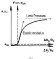
- FIG. 4 illustrates one method of using the Sleeve Fracture Plot (packer pressure vs. pumped volume) to derive information on rock mechanics properties.
- FIG. 4 shows one possible procedure to perform a PMT test and an exemplary result of a PMT test in soils. Two slopes can be used to characterize the elastic modulus (subvertical arrow) and the limit (failure) pressure (horizontal arrow).
- the PMT curve can be used to derive the static shear modulus G ( FIG. 5 Bottom, adapted from Briaud, 1992).
- K 0 coefficient of earth pressure at rest, which can be further used in isotropic elasticity
- PMT modulus E 0 and reload modulus E r for a given Poisson's ratio
- Standard soils classification e.g. ASTM
- E 0 /P* also used for test quality check
- friction angle coefficient of radial consolidation, tensile strength, and pre-consolidation pressure.
- FIG. 6 One example of a sleeve fracture plot with two packer inflation phases is presented in FIG. 6 .
- a similar curve from PMT is shown in FIG. 7 (after Briaud, 1992).
- the slope of the linear part plotted as a function of the pumped volume can be interpreted following the scheme presented in FIG. 5 and can provide the value of the static shear modulus G.
- Embodiments of the current application also comprises the workflow as illustrated in FIG. 8 . It enables the exploitation of data from the packer inflation in order to derive elastic static properties directly down-hole within an extremely short period (e.g. a few hours). Currently the typical time necessary to obtain similar information is of the order of months since static mechanical properties are obtained by means of laboratory tests on samples extracted from cores.
- Embodiments of the current application may further comprise a real time (RT) interface developed as a standalone application or a module extension in a platform acquisition software program, enabling the interpretation of the packer(s) inflation phases in terms of packers pressure vs. injected volume (P-V inflation curves).
- RT real time
- the module allows the application of theoretical solution derived from the cavity expansion theory (e.g. Yu, H-S 1990) by means of a numerical analysis.
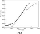
- One embodiment of the solution is shown as a curve in FIG. 9 . This curve can also serve as a quality control indicator of the in-situ conditions with respect to the expected theoretical solution.
- the module may also allow drawing various secant slopes of the pressure-volume inflation curve, extracting the most suitable value of the slope (equal to 2G, being G the static elastic shear modulus) that minimize the error of the proposed interpolation (e.g. the straight line in FIG. 9 ).
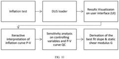
- One example of the high level workflow of the interpretation software is illustrated in FIG. 10 .
Landscapes
- Life Sciences & Earth Sciences (AREA)
- Engineering & Computer Science (AREA)
- Geology (AREA)
- Mining & Mineral Resources (AREA)
- Physics & Mathematics (AREA)
- Environmental & Geological Engineering (AREA)
- Fluid Mechanics (AREA)
- General Life Sciences & Earth Sciences (AREA)
- Geochemistry & Mineralogy (AREA)
- Geophysics (AREA)
- Investigation Of Foundation Soil And Reinforcement Of Foundation Soil By Compacting Or Drainage (AREA)
Description
- This disclosure relates generally to methods for using downhole tools and more specifically to methods for using tools for evaluating static elastic modulus of subterranean formation.
-
US 5353637 describes a method of determining stress in a bed of an underground formation having multiple lithological beds traversed by a borehole comprising positioning an inflatable packer in a location of the borehole passing through a predetermined bed and controllably pressurizing the packer in a sequence of pressurization steps while monitoring a plurality of parameters, wherein the parameters include packer inflation pressure (P), radial displacement (U) of the borehole wall at multiple locations about an axis passing through the packer, packer inflation volume (V), and acoustic emissions (AE) in the vicinity of the packer. The sequence of pressurization steps includes, inflating the packer until the packer contacts the formation surrounding the borehole as indicated by at least one of the monitored parameters, inflating and deflating the packer a plurality of times in a series of cycles in which the packer inflation pressure is progressively increased and is maintained below the formation breakdown pressure to thereby apply a series of load-unload cycles useful in determining elasticity of the formation bed, increasing packer inflation pressure until formation fracture is indicated by a decrease in the rate of increase of packer inflation pressure and an increase in the rate of packer inflation volume as packer inflation pressure approaches a first formation breakdown pressure, maintaining packer inflation pressure at the first formation breakdown pressure for a time interval, reducing packer inflation pressure below the first formation breakdown pressure to allow the formation fracture to close, increasing packer inflation pressure until fracture re-opening is indicated by radial displacement of the borehole wall and by packer inflation volume as packer inflation pressure approaches a fracture re-opening pressure and increasing packer inflation pressure beyond the fracture re-opening pressure to extend the first fracture, extension of the fracture being indicated by an increase of acoustic emissions and increase of packer inflation volume (V). Principal stress (Sh) of the formation is determined from the monitored parameters. - One or more specific embodiments of the present disclosure will be described below. These described embodiments are only examples of the presently disclosed techniques. Additionally, in an effort to provide a concise description of these embodiments, all features of an actual implementation may not be described in the specification. It should be appreciated that in the development of any such actual implementation, as in any engineering or design project, numerous implementation-specific decisions must be made to achieve the developers' specific goals, such as compliance with system-related and business-related constraints, which may vary from one implementation to another. Moreover, it should be appreciated that such a development
effort might be complex and time consuming, but would nevertheless be a routine undertaking of design, fabrication, and manufacture for those of ordinary skill having the benefit of this disclosure. - Various aspects of this disclosure may be better understood upon reading the following detailed description and upon reference to the drawings in which:
-
FIG. 1 depict examples of wellsite systems that may employ the formation tester and techniques described herein; -
FIG. 2 depict examples of wellsite systems that may employ the formation tester and techniques described herein; -
FIG. 3 is a schematic diagram illustrating a traditional PMT test (in comparison to an embodiment of the current application which uses a formation testing module of thedownhole tool 100 to perform a PMT test; -
FIG. 4 illustrates one method of using the Sleeve Fracture Plot (packer pressure vs. pumped volume) to derive information on rock mechanics properties; -
FIG. 5 depicts means of the cavity expansion theory; -
FIG. 6 depicts example of a sleeve fracture plot with two packer inflation phases; and -
FIG. 7 depicts an example curve from a PMT; -
FIG. 8 depicts an example workflow; -
FIG. 9 solution derived from the cavity expansion theory; -
FIG. 10 example of a high level workflow of interpretation software. - In one aspect of the present disclosure there is provided a method as specified in
claim 1. - Formation testing provides information about the properties of a subsurface formation such as the minimum horizontal stress, which may be useful for optimizing the extraction of oil and gas from a subsurface formation. During formation testing, a downhole tool is inserted into a wellbore and different tests can be conducted on the subsurface formation while the downhole tool is positioned in the wellbore.
- In some instances, it is desirable to conduct one or more pressuremeter tests (PMT) with the downhole tool in the wellbore. In some embodiments, a PMT test may comprise inflating an inflatable probe or packer to expand the probe or packer against the wall of the wellbore to induce an outward radial deformation. Accordingly, the present disclosure provides an efficient solution to perform PMT tests that may be used as an alternative or in addition to certain conventional techniques. Aspects in accordance with the present disclosure may be applied to, for example, cases where the formation is normally consolidated or unconsolidated. Embodiments of the present disclosure may include downhole tools with double packers (e.g. straddle packers) or single packer.
- With the foregoing in mind,
FIGS. 1 and2 depict examples of wellsite systems that may employ the formation tester and techniques described herein.FIG. 1 depicts arig 10 with adownhole acquisition tool 12 suspended therefrom and into awellbore 14 of areservoir 15 via adrill string 16. Thedownhole acquisition tool 12 has adrill bit 18 at its lower end thereof that is used to advance thedownhole acquisition tool 12 intogeological formation 20 and form thewellbore 14. Thedrill string 16 is rotated by a rotary table 24, energized by means not shown, which engages a kelly 26 at the upper end of thedrill string 16. Thedrill string 16 is suspended from ahook 28, attached to a traveling block (also not shown), through thekelly 26 and arotary swivel 30 that permits rotation of thedrill string 16 relative to thehook 28. Therig 10 is depicted as a land-based platform and derrick assembly used to form thewellbore 14 by rotary drilling. However, in other embodiments, therig 10 may be an offshore platform. - Formation fluid or mud 32 (e.g., oil base mud (OBM) or water-based mud (WBM)) is stored in a
pit 34 formed at the well site. Apump 36 delivers theformation fluid 52 to the interior of thedrill string 16 via a port in the swivel 30, inducing thedrilling mud 32 to flow downwardly through thedrill string 16 as indicated by adirectional arrow 38. The formation fluid exits thedrill string 16 via ports in thedrill bit 18, and then circulates upwardly through the region between the outside of thedrill string 16 and the wall of thewellbore 14, called the annulus, as indicated bydirectional arrows 40. Thedrilling mud 32 lubricates thedrill bit 18 and carries formation cuttings up to the surface as it is returned to thepit 34 for recirculation. - The
downhole acquisition tool 12, sometimes referred to as a bottom hole assembly ("BHA"), may be positioned near thedrill bit 18 and includes various components with capabilities, such as measuring, processing, and storing information, as well as communicating with the surface. A telemetry device (not shown) also may be provided for communicating with a surface unit (not shown). As should be noted, thedownhole acquisition tool 12 may be conveyed on wired drill pipe, a combination of wired drill pipe and wireline, or other suitable types of conveyance. - In certain embodiments, the
downhole acquisition tool 12 includes a downhole analysis system. For example, thedownhole acquisition tool 12 may include asampling system 42 including afluid communication module 46 and asampling module 48. The modules may be housed in a drill collar for performing various formation evaluation functions, such as pressure testing and fluid sampling, among others. As shown inFIG. 1 , thefluid communication module 46 is positioned adjacent thesampling module 48; however the position of thefluid communication module 46, as well as other modules, may vary in other embodiments. Additional devices, such as pumps, gauges, sensor, monitors or other devices usable in downhole sampling and/or testing also may be provided. The additional devices may be incorporated intomodules sampling system 42. - In certain embodiments, the
downhole acquisition tool 12 includes a logging while drilling (LWD)module 68. Themodule 68 includes a radiation source that emits radiation (e.g., gamma rays) into theformation 20 to determine formation properties such as, e.g., lithology, density, formation geometry, reservoir boundaries, among others. The gamma rays interact with the formation through Compton scattering, which may attenuate the gamma rays. Sensors within themodule 68 may detect the scattered gamma rays and determine the geological characteristics of theformation 20 based at least in part on the attenuated gamma rays. - The sensors within the
downhole acquisition tool 12 may collect and transmit data 70 (e.g., log and/or DFA data) associated with the characteristics of theformation 20 and/or the fluid properties and the composition of thereservoir fluid 50 to a control anddata acquisition system 72 atsurface 74, where thedata 70 may be stored and processed in adata processing system 76 of the control anddata acquisition system 72. - The
data processing system 76 may include aprocessor 78,memory 80,storage 82, and/ordisplay 84. Thememory 80 may include one or more tangible, non-transitory, machine readable media collectively storing one or more sets of instructions for operating thedownhole acquisition tool 12, determining formation characteristics (e.g., geometry, connectivity, minimum horizontal stress, etc.) calculating and estimating fluid properties of thereservoir fluid 50, modeling the fluid behaviors using, e.g., equation of state models (EOS). Thememory 80 may store reservoir modeling systems (e.g., geological process models, petroleum systems models, reservoir dynamics models, etc.), mixing rules and models associated with compositional characteristics of thereservoir fluid 50, equation of state (EOS) models for equilibrium and dynamic fluid behaviors (e.g., biodegradation, gas/condensate charge into oil, CO2 charge into oil, fault block migration/subsidence, convective currents, among others), and any other information that may be used to determine geological and fluid characteristics of theformation 20 andreservoir fluid 52, respectively. In certain embodiments, the data processing system 54 may apply filters to remove noise from thedata 70. - To process the
data 70, theprocessor 78 may execute instructions stored in thememory 80 and/orstorage 82. For example, the instructions may cause the processor to compare the data 70 (e.g., from the logging while drilling and/or downhole analysis) with known reservoir properties estimated using the reservoir modeling systems, use thedata 70 as inputs for the reservoir modeling systems, and identify geological and reservoir fluid parameters that may be used for exploration and production of the reservoir. As such, thememory 80 and/orstorage 82 of thedata processing system 76 may be any suitable article of manufacture that can store the instructions. By way of example, thememory 80 and/or thestorage 82 may be ROM memory, random-access memory (RAM), flash memory, an optical storage medium, or a hard disk drive. Thedisplay 84 may be any suitable electronic display that can display information (e.g., logs, tables, cross-plots, reservoir maps, etc.) relating to properties of the well/reservoir as measured by thedownhole acquisition tool 12. It should be appreciated that, although thedata processing system 76 is shown by way of example as being located at thesurface 74, thedata processing system 76 may be located in thedownhole acquisition tool 12. In such embodiments, some of thedata 70 may be processed and stored downhole (e.g., within the wellbore 14), while some of thedata 70 may be sent to the surface 74 (e.g., in real time). In certain embodiments, thedata processing system 76 may use information obtained from petroleum system modeling operations, ad hoc assertions from the operator, empirical historical data (e.g., case study reservoir data) in combination with or lieu of thedata 70 to determine certain parameters of the reservoir 8. -
FIG. 2 depicts an example of a wirelinedownhole tool 100 that may employ the systems and techniques described herein to determine formation and fluid property characteristics of thereservoir 15. The wireline downholetool 100 is suspended in the wellbore 14 from the lower end of amulti-conductor cable 104 that is spooled on a winch at thesurface 74. Similar to thedownhole acquisition tool 12, the wirelinedownhole tool 100 may be conveyed on wired drill pipe, a combination of wired drill pipe and wireline, or other suitable types of conveyance. Thecable 104 is communicatively coupled to an electronics andprocessing system 106. The wireline downholetool 100 includes anelongated body 108 that housesmodules modules - As shown in
FIG. 2 , themodule 114 is afluid communication module 114 that has a selectively extendable probe orpacker 116 andbackup pistons 118 that are arranged on opposite sides of theelongated body 108. The extendable probe orpacker 116 is configured to selectively seal off or isolate selected portions of thewall 58 of thewellbore 14 to fluidly couple to the adjacentgeological formation 20 and/or to draw fluid samples from thegeological formation 20. The extendable probe orpacker 116 may include a single inlet or multiple inlets designed for guarded or focused sampling. Thereservoir fluid 50 may be expelled to the wellbore through a port in thebody 108 or theformation fluid 50 may be sent to one ormore modules modules reservoir fluid 50. In the illustrated example, the electronics andprocessing system 106 and/or a downhole control system are configured to control the extendable probe orpacker 116 and/or the drawing of a fluid sample from theformation 20 to enable analysis of the fluid properties of thereservoir fluid 50, as discussed above. - In some embodiments, the
module 114 may be used for formation testing. For example, it may be desirable to conduct one or more pressuremeter tests (PMT) with the downhole tool in the wellbore. In some embodiments, a PMT test may comprise inflating an inflatable probe orpacker 116 to expand the probe orpacker 116 against the wall of the wellbore to induce an outward radial deformation. One or more of the extendable probes orpackers 116 may be used to deform radially thegeological formation 20, increasing the number of points where measurements are taken . The extendable probes orpackers 116 may be coupled to one or moreformation testing module 122 and/or 124, which determine a property of the formation. - A PMT test can be run under pressure controlled conditions (constant pressure rate) or strain controlled conditions (constant volume rate). The PMT test supports shallow and deep foundations design (onshore and offshore) by providing elastic and strength geomechanical parameters such as: pressuremeter modulus, shear static modulus, limit expansion pressure, shear strength, . The shear static modulus is of particular interest for formation characterization since it is a static property derived from a direct measurement down-hole. A modular formation testing tool with probe/packer(s) can be used to conduct PMT tests because it possesses the geometrical and mechanical attributes, for example a long cylindrical membrane in single or multiple packers, that are capable of expansion to deform the surrounding soil/rock mass.
FIG. 3 is a schematic diagram illustrating a traditional PMT test (left, after Briaud, 1992) in comparison to an embodiment of the current application which uses aformation testing module 122 of thedownhole tool 100 to perform a PMT test (right). - Accordingly, the current application discloses a tool or system and procedures associated thereof to perform PMT tests to assess in situ static elastic properties of consolidated and unconsolidated rock formations using a wireline formation testing tool. The analysis and design of the current tool and procedure can be of great benefit for the general deployment of engineering solutions associated to PMT testing. In embodiments, the analysis can be carried out by inspecting the packer pressure vs. pumped volume in a Sleeve Fracture Plot, before inducing irreversible formation deformations such as tangential plastic yielding and/or plastic tensile failure. Compared to the traditional PMT test, one advantage of the current application is the possibility to reproduce by means of an in situ nondestructive test a mechanical problem that can be fully tackled using the well-known cavity expansion theory.
- The combined use of test results from a formation testing tool and the cavity expansion theory approach can allow inferring rock in situ elastic and strength properties in a very short period of time such as a few hours. The derived information can be used for multiple applications, including but not limited to, geomechanical parameters calibration, formation characterization, local (packer level) stress analysis, evaluation of formation damage in conjunction with acoustic emissions measurements, influence of near wellbore stress changes induced by packers on fracture inception.
-
FIG. 4 (adapted from Briaud, 1992) illustrates one method of using the Sleeve Fracture Plot (packer pressure vs. pumped volume) to derive information on rock mechanics properties.FIG. 4 shows one possible procedure to perform a PMT test and an exemplary result of a PMT test in soils. Two slopes can be used to characterize the elastic modulus (subvertical arrow) and the limit (failure) pressure (horizontal arrow). By means of the cavity expansion theory (FIG. 5 Top, adapted from Briaud, 1992) the PMT curve can be used to derive the static shear modulus G (FIG. 5 Bottom, adapted from Briaud, 1992). Additional parameters that can be derived from PMT test, including but not limited to: K0 (coefficient of earth pressure at rest, which can be further used in isotropic elasticity K0=v/(1-v) to derive v=Poisson's ratio), PMT modulus E0 and reload modulus Er (for a given Poisson's ratio), Yield, Limit and Net Limit pressures (PY, PL, P*), Standard soils classification (e.g. ASTM) based on ratio E0/P* (also used for test quality check), friction angle, coefficient of radial consolidation, tensile strength, and pre-consolidation pressure. - One example of a sleeve fracture plot with two packer inflation phases is presented in
FIG. 6 . A similar curve from PMT is shown inFIG. 7 (after Briaud, 1992). The slope of the linear part plotted as a function of the pumped volume can be interpreted following the scheme presented inFIG. 5 and can provide the value of the static shear modulus G. - Embodiments of the current application also comprises the workflow as illustrated in
FIG. 8 . It enables the exploitation of data from the packer inflation in order to derive elastic static properties directly down-hole within an extremely short period (e.g. a few hours). Currently the typical time necessary to obtain similar information is of the order of months since static mechanical properties are obtained by means of laboratory tests on samples extracted from cores. - Embodiments of the current application may further comprise a real time (RT) interface developed as a standalone application or a module extension in a platform acquisition software program, enabling the interpretation of the packer(s) inflation phases in terms of packers pressure vs. injected volume (P-V inflation curves).
- The module allows the application of theoretical solution derived from the cavity expansion theory (e.g. Yu, H-S 1990) by means of a numerical analysis. One embodiment of the solution is shown as a curve in
FIG. 9 . This curve can also serve as a quality control indicator of the in-situ conditions with respect to the expected theoretical solution. - The module may also allow drawing various secant slopes of the pressure-volume inflation curve, extracting the most suitable value of the slope (equal to 2G, being G the static elastic shear modulus) that minimize the error of the proposed interpolation (e.g. the straight line in
FIG. 9 ). One example of the high level workflow of the interpretation software is illustrated inFIG. 10 . - The invention is defined by the features specified in the appended claims.
- The following references are pointed out:
- [1] Briaud J-L. 1992. The pressuremeter. Taylor and Francis, 336 p.
- [2] Yu, H-S 1990. Cavity expansion theory and its application to the analysis of pressuremeters. PhD thesis, University of Oxford.
- [3] Règles techniques de calcul et de conception des fondations des ouvrages de genie civil. Cahier des clauses techniques générales applicables aux marches des travaux. .
- [4] Essai pressiometrique Menard. Norme française NF P 94-110, juillet 1991, AFNOR Paris.
- [5] American Petroleum Institute. .
- [6] Standard tests methods for prebored pressuremeter testing in soils. ASTM D 4719.
Claims (9)
- A method, comprising:(a) lowering a formation testing tool (100) into a wellbore (14) intersecting a subterranean formation, wherein the formation testing tool comprises an expandable member (116);(b) performing a pressure meter test (PMT) by expanding the expandable member (116).(c) providing packer pressure data and pumped volume data obtained during the PMT to a processor (78);(d) generating a Sleeve Fracture Plot with the processor (78) using the received PMT data; and(e) using cavity expansion theory to generate an in situ stress-strain curve from received PMT data and Sleeve Fracture Plot to derive a static shear modulus therefrom.
- The method of claim 1, extending the traditional shallow depths applications of PMT to subterranean formation at high depths and more competent rocks.
- The method of claim 1, wherein the formation testing tool is a wireline tool (100).
- The method of claim 1, wherein the expandable member (116) is a packer inflated by downhole pumps.
- The method of claim 1, wherein the expandable member (116) comprises multiple packers.
- The method of claim 1, further comprising considering proper tool calibration and packer selection as a function of formation stiffness before test execution.
- The method of claim 1, further validating interpretation using rock mechanics laboratory tests results when available.
- The method of claim 1, further integrating acoustic based estimation of dynamic elastic properties, comprising isotropic and anisotropic from wireline logging in order to establish appropriate dynamic-to-static transforms and support geomechanical properties and stress modelling.
- The method of claim 1, wherein the formation testing tool comprises a plurality of expandable members (116); and
wherein performing a pressure meter test (PMT) comprises:performing a first PMT test at a first depth by inflating a first expandable packer (116), and acquiring pressure and pumped volume data, and communicating the acquired pumped volume data and pressure data to the processor (78), wherein the processor (78) is configured to plot a first sleeve facture plot;performing a second PMT test by inflating a second expandable packer (116), and acquiring pressure and pumped volume data, and communicating the acquired pumped volume data and pressure data to the processor (78), wherein the processor (78) is configured to plot a second sleeve fracture plot; andusing the processor (78) to derive a first static shear modulus using the first sleeve fracture plot and a second static shear modulus using the second sleeve fracture plot.
Applications Claiming Priority (2)
| Application Number | Priority Date | Filing Date | Title |
|---|---|---|---|
| US201962828787P | 2019-04-03 | 2019-04-03 | |
| PCT/US2020/026644 WO2020206303A1 (en) | 2019-04-03 | 2020-04-03 | System and method for evaluating static elastic modulus of subterranean formation |
Publications (3)
| Publication Number | Publication Date |
|---|---|
| EP3947909A1 EP3947909A1 (en) | 2022-02-09 |
| EP3947909A4 EP3947909A4 (en) | 2022-11-30 |
| EP3947909B1 true EP3947909B1 (en) | 2024-07-31 |
Family
ID=72667413
Family Applications (1)
| Application Number | Title | Priority Date | Filing Date |
|---|---|---|---|
| EP20782160.4A Active EP3947909B1 (en) | 2019-04-03 | 2020-04-03 | System and method for evaluating static elastic modulus of subterranean formation |
Country Status (4)
| Country | Link |
|---|---|
| US (1) | US12037898B2 (en) |
| EP (1) | EP3947909B1 (en) |
| DK (1) | DK3947909T3 (en) |
| WO (1) | WO2020206303A1 (en) |
Cited By (1)
| Publication number | Priority date | Publication date | Assignee | Title |
|---|---|---|---|---|
| WO2026033286A1 (en) * | 2024-08-07 | 2026-02-12 | Luca MAGINI | Method, system and device for performing geomechanical tests in the rock of hydrocarbon extraction wells during drilling |
Families Citing this family (6)
| Publication number | Priority date | Publication date | Assignee | Title |
|---|---|---|---|---|
| EP4264013A4 (en) * | 2020-12-21 | 2024-11-13 | Services Pétroliers Schlumberger | Pressure meter testing apparatus and method |
| WO2022139982A1 (en) | 2020-12-21 | 2022-06-30 | Schlumberger Technology Corporation | Pressure meter testing apparatus and method |
| CN112858018B (en) * | 2021-01-08 | 2022-06-28 | 青岛海洋地质研究所 | Apparatus and method for lateral pressure creep test of hydrate-containing sediments |
| US12196079B2 (en) * | 2023-04-24 | 2025-01-14 | Halliburton Energy Services, Inc. | Downhole testing tool for subterranean formation testing using a fluid sampling probe assembly |
| WO2025245478A1 (en) * | 2024-05-24 | 2025-11-27 | Schlumberger Technology Corporation | Systems and methods for measurement of formation elastic moduli with a borehole dual packer apparatus |
| US12584408B1 (en) | 2025-02-24 | 2026-03-24 | Halliburton Energy Services, Inc. | Formation fluid sampling using probe with inflatable pad |
Family Cites Families (16)
| Publication number | Priority date | Publication date | Assignee | Title |
|---|---|---|---|---|
| US4149409A (en) * | 1977-11-14 | 1979-04-17 | Shosei Serata | Borehole stress property measuring system |
| FR2496751A1 (en) | 1980-12-24 | 1982-06-25 | Petroles Cie Francaise | Geo-mechanical probe for oil exploration - where probe contains inflatable membrane driven against wall of drilled hole to determine properties of earth |
| US4899320A (en) * | 1985-07-05 | 1990-02-06 | Atlantic Richfield Company | Downhole tool for determining in-situ formation stress orientation |
| FR2648232B1 (en) * | 1989-06-09 | 1991-09-27 | Erg | METHOD AND DEVICE FOR IN SITU MEASUREMENT OF SWELLING CHARACTERISTICS OF A SOIL |
| US5353637A (en) | 1992-06-09 | 1994-10-11 | Plumb Richard A | Methods and apparatus for borehole measurement of formation stress |
| US5784333A (en) * | 1997-05-21 | 1998-07-21 | Western Atlas International, Inc. | Method for estimating permeability of earth formations by processing stoneley waves from an acoustic wellbore logging instrument |
| US6213217B1 (en) * | 1999-04-15 | 2001-04-10 | Weatherford International, Inc. | Gas operated apparatus and method for maintaining relatively uniformed fluid pressure within an expandable well tool subjected to thermal variants |
| US20040237640A1 (en) * | 2003-05-29 | 2004-12-02 | Baker Hughes, Incorporated | Method and apparatus for measuring in-situ rock moduli and strength |
| US7392851B2 (en) * | 2004-11-04 | 2008-07-01 | Schlumberger Technology Corporation | Inflatable packer assembly |
| US8171990B2 (en) * | 2007-11-27 | 2012-05-08 | Baker Hughes Incorporated | In-situ formation strength testing with coring |
| EP2225440A4 (en) * | 2007-11-27 | 2012-04-04 | Baker Hughes Inc | In-situ formations strength testing with formation sampling |
| EP2391800A2 (en) | 2009-01-13 | 2011-12-07 | Schlumberger Technology B.V. | In-situ stress measurements in hydrocarbon bearing shales |
| US8146416B2 (en) * | 2009-02-13 | 2012-04-03 | Schlumberger Technology Corporation | Methods and apparatus to perform stress testing of geological formations |
| US8763696B2 (en) * | 2010-04-27 | 2014-07-01 | Sylvain Bedouet | Formation testing |
| CA2861774C (en) | 2013-09-30 | 2017-02-14 | 1464684 Alberta Limited O/A Integrity Insitu | In-situ rock testing tool |
| US10738600B2 (en) * | 2017-05-19 | 2020-08-11 | Baker Hughes, A Ge Company, Llc | One run reservoir evaluation and stimulation while drilling |
-
2020
- 2020-04-03 WO PCT/US2020/026644 patent/WO2020206303A1/en not_active Ceased
- 2020-04-03 US US17/594,082 patent/US12037898B2/en active Active
- 2020-04-03 EP EP20782160.4A patent/EP3947909B1/en active Active
- 2020-04-03 DK DK20782160.4T patent/DK3947909T3/en active
Cited By (1)
| Publication number | Priority date | Publication date | Assignee | Title |
|---|---|---|---|---|
| WO2026033286A1 (en) * | 2024-08-07 | 2026-02-12 | Luca MAGINI | Method, system and device for performing geomechanical tests in the rock of hydrocarbon extraction wells during drilling |
Also Published As
| Publication number | Publication date |
|---|---|
| WO2020206303A1 (en) | 2020-10-08 |
| US20220178251A1 (en) | 2022-06-09 |
| EP3947909A1 (en) | 2022-02-09 |
| EP3947909A4 (en) | 2022-11-30 |
| DK3947909T3 (en) | 2024-11-04 |
| US12037898B2 (en) | 2024-07-16 |
Similar Documents
| Publication | Publication Date | Title |
|---|---|---|
| US12037898B2 (en) | System and method for evaluating static elastic modulus of subterranean formation | |
| CN108713089B (en) | Estimating formation properties based on borehole fluid and drilling logs | |
| US10385687B2 (en) | Determining the imminent rock failure state for improving multi-stage triaxial compression tests | |
| US6904365B2 (en) | Methods and systems for determining formation properties and in-situ stresses | |
| US9091781B2 (en) | Method for estimating formation permeability using time lapse measurements | |
| US9303508B2 (en) | In-situ stress measurements in hydrocarbon bearing shales | |
| US20170131192A1 (en) | Determining the imminent rock failure state for improving multi-stage triaxial compression tests | |
| CN106795748B (en) | One or more parameters of the completion design are determined based on drilling data corresponding to the variable of mechanical specific energy | |
| NO20221053A1 (en) | Surface logging with cuttings-based rock petrophysics analysis | |
| US7753118B2 (en) | Method and tool for evaluating fluid dynamic properties of a cement annulus surrounding a casing | |
| US11579333B2 (en) | Methods and systems for determining reservoir properties from motor data while coring | |
| WO2018027089A1 (en) | Automatic petro-physical log quality control | |
| US20250138219A1 (en) | Determination of 3d minimum horizontal stress for naturally fractured reservoirs | |
| EP3455457A1 (en) | Methods and systems for optimizing a drilling operation based on multiple formation measurements | |
| US12577856B2 (en) | System and method for methane hydrate based production prediction | |
| US20210381363A1 (en) | Relative permeability estimation methods and systems employing downhole pressure transient analysis, saturation analysis, and porosity analysis | |
| Elkhoury et al. | The first pressuremeter testing campaign on wireline formation testers in deep boreholes | |
| EP4211335B1 (en) | Geologic formation characterization | |
| US11933776B2 (en) | Pressure meter testing apparatus and method | |
| US20220356800A1 (en) | Drilling Quasi-Stationary Data Extraction And Processing | |
| US10767472B2 (en) | System and method for controlled flowback | |
| Pei et al. | Constraining in-situ stresses at BETA by analysis of borehole images and downhole pressure data | |
| WO2022139982A1 (en) | Pressure meter testing apparatus and method | |
| BR112022018232B1 (en) | DRILLING PROCESSING METHOD AND DRILLING SYSTEM | |
| Elkhoury et al. | Geomechanics for Energy and the Environment |
Legal Events
| Date | Code | Title | Description |
|---|---|---|---|
| STAA | Information on the status of an ep patent application or granted ep patent |
Free format text: STATUS: THE INTERNATIONAL PUBLICATION HAS BEEN MADE |
|
| PUAI | Public reference made under article 153(3) epc to a published international application that has entered the european phase |
Free format text: ORIGINAL CODE: 0009012 |
|
| STAA | Information on the status of an ep patent application or granted ep patent |
Free format text: STATUS: REQUEST FOR EXAMINATION WAS MADE |
|
| 17P | Request for examination filed |
Effective date: 20211004 |
|
| AK | Designated contracting states |
Kind code of ref document: A1 Designated state(s): AL AT BE BG CH CY CZ DE DK EE ES FI FR GB GR HR HU IE IS IT LI LT LU LV MC MK MT NL NO PL PT RO RS SE SI SK SM TR |
|
| DAV | Request for validation of the european patent (deleted) | ||
| DAX | Request for extension of the european patent (deleted) | ||
| A4 | Supplementary search report drawn up and despatched |
Effective date: 20221103 |
|
| RIC1 | Information provided on ipc code assigned before grant |
Ipc: E21B 43/12 20060101ALI20221027BHEP Ipc: E21B 47/09 20120101ALI20221027BHEP Ipc: E21B 47/06 20120101ALI20221027BHEP Ipc: E21B 49/00 20060101AFI20221027BHEP |
|
| GRAP | Despatch of communication of intention to grant a patent |
Free format text: ORIGINAL CODE: EPIDOSNIGR1 |
|
| STAA | Information on the status of an ep patent application or granted ep patent |
Free format text: STATUS: GRANT OF PATENT IS INTENDED |
|
| INTG | Intention to grant announced |
Effective date: 20240315 |
|
| GRAS | Grant fee paid |
Free format text: ORIGINAL CODE: EPIDOSNIGR3 |
|
| GRAA | (expected) grant |
Free format text: ORIGINAL CODE: 0009210 |
|
| STAA | Information on the status of an ep patent application or granted ep patent |
Free format text: STATUS: THE PATENT HAS BEEN GRANTED |
|
| AK | Designated contracting states |
Kind code of ref document: B1 Designated state(s): AL AT BE BG CH CY CZ DE DK EE ES FI FR GB GR HR HU IE IS IT LI LT LU LV MC MK MT NL NO PL PT RO RS SE SI SK SM TR |
|
| REG | Reference to a national code |
Ref country code: CH Ref legal event code: EP Ref country code: GB Ref legal event code: FG4D |
|
| REG | Reference to a national code |
Ref country code: DE Ref legal event code: R096 Ref document number: 602020034947 Country of ref document: DE |
|
| REG | Reference to a national code |
Ref country code: IE Ref legal event code: FG4D |
|
| REG | Reference to a national code |
Ref country code: DK Ref legal event code: T3 Effective date: 20241030 |
|
| REG | Reference to a national code |
Ref country code: LT Ref legal event code: MG9D |
|
| REG | Reference to a national code |
Ref country code: NL Ref legal event code: MP Effective date: 20240731 |
|
| PG25 | Lapsed in a contracting state [announced via postgrant information from national office to epo] |
Ref country code: PT Free format text: LAPSE BECAUSE OF FAILURE TO SUBMIT A TRANSLATION OF THE DESCRIPTION OR TO PAY THE FEE WITHIN THE PRESCRIBED TIME-LIMIT Effective date: 20241202 |
|
| REG | Reference to a national code |
Ref country code: AT Ref legal event code: MK05 Ref document number: 1708628 Country of ref document: AT Kind code of ref document: T Effective date: 20240731 |
|
| PG25 | Lapsed in a contracting state [announced via postgrant information from national office to epo] |
Ref country code: PT Free format text: LAPSE BECAUSE OF FAILURE TO SUBMIT A TRANSLATION OF THE DESCRIPTION OR TO PAY THE FEE WITHIN THE PRESCRIBED TIME-LIMIT Effective date: 20241202 |
|
| PG25 | Lapsed in a contracting state [announced via postgrant information from national office to epo] |
Ref country code: FI Free format text: LAPSE BECAUSE OF FAILURE TO SUBMIT A TRANSLATION OF THE DESCRIPTION OR TO PAY THE FEE WITHIN THE PRESCRIBED TIME-LIMIT Effective date: 20240731 Ref country code: NL Free format text: LAPSE BECAUSE OF FAILURE TO SUBMIT A TRANSLATION OF THE DESCRIPTION OR TO PAY THE FEE WITHIN THE PRESCRIBED TIME-LIMIT Effective date: 20240731 Ref country code: GR Free format text: LAPSE BECAUSE OF FAILURE TO SUBMIT A TRANSLATION OF THE DESCRIPTION OR TO PAY THE FEE WITHIN THE PRESCRIBED TIME-LIMIT Effective date: 20241101 Ref country code: PL Free format text: LAPSE BECAUSE OF FAILURE TO SUBMIT A TRANSLATION OF THE DESCRIPTION OR TO PAY THE FEE WITHIN THE PRESCRIBED TIME-LIMIT Effective date: 20240731 |
|
| PG25 | Lapsed in a contracting state [announced via postgrant information from national office to epo] |
Ref country code: BG Free format text: LAPSE BECAUSE OF FAILURE TO SUBMIT A TRANSLATION OF THE DESCRIPTION OR TO PAY THE FEE WITHIN THE PRESCRIBED TIME-LIMIT Effective date: 20240731 |
|
| PG25 | Lapsed in a contracting state [announced via postgrant information from national office to epo] |
Ref country code: LV Free format text: LAPSE BECAUSE OF FAILURE TO SUBMIT A TRANSLATION OF THE DESCRIPTION OR TO PAY THE FEE WITHIN THE PRESCRIBED TIME-LIMIT Effective date: 20240731 |
|
| PG25 | Lapsed in a contracting state [announced via postgrant information from national office to epo] |
Ref country code: AT Free format text: LAPSE BECAUSE OF FAILURE TO SUBMIT A TRANSLATION OF THE DESCRIPTION OR TO PAY THE FEE WITHIN THE PRESCRIBED TIME-LIMIT Effective date: 20240731 Ref country code: IS Free format text: LAPSE BECAUSE OF FAILURE TO SUBMIT A TRANSLATION OF THE DESCRIPTION OR TO PAY THE FEE WITHIN THE PRESCRIBED TIME-LIMIT Effective date: 20241130 |
|
| PG25 | Lapsed in a contracting state [announced via postgrant information from national office to epo] |
Ref country code: HR Free format text: LAPSE BECAUSE OF FAILURE TO SUBMIT A TRANSLATION OF THE DESCRIPTION OR TO PAY THE FEE WITHIN THE PRESCRIBED TIME-LIMIT Effective date: 20240731 |
|
| PG25 | Lapsed in a contracting state [announced via postgrant information from national office to epo] |
Ref country code: RS Free format text: LAPSE BECAUSE OF FAILURE TO SUBMIT A TRANSLATION OF THE DESCRIPTION OR TO PAY THE FEE WITHIN THE PRESCRIBED TIME-LIMIT Effective date: 20241031 Ref country code: ES Free format text: LAPSE BECAUSE OF FAILURE TO SUBMIT A TRANSLATION OF THE DESCRIPTION OR TO PAY THE FEE WITHIN THE PRESCRIBED TIME-LIMIT Effective date: 20240731 |
|
| PG25 | Lapsed in a contracting state [announced via postgrant information from national office to epo] |
Ref country code: RS Free format text: LAPSE BECAUSE OF FAILURE TO SUBMIT A TRANSLATION OF THE DESCRIPTION OR TO PAY THE FEE WITHIN THE PRESCRIBED TIME-LIMIT Effective date: 20241031 Ref country code: PL Free format text: LAPSE BECAUSE OF FAILURE TO SUBMIT A TRANSLATION OF THE DESCRIPTION OR TO PAY THE FEE WITHIN THE PRESCRIBED TIME-LIMIT Effective date: 20240731 Ref country code: NL Free format text: LAPSE BECAUSE OF FAILURE TO SUBMIT A TRANSLATION OF THE DESCRIPTION OR TO PAY THE FEE WITHIN THE PRESCRIBED TIME-LIMIT Effective date: 20240731 Ref country code: LV Free format text: LAPSE BECAUSE OF FAILURE TO SUBMIT A TRANSLATION OF THE DESCRIPTION OR TO PAY THE FEE WITHIN THE PRESCRIBED TIME-LIMIT Effective date: 20240731 Ref country code: IS Free format text: LAPSE BECAUSE OF FAILURE TO SUBMIT A TRANSLATION OF THE DESCRIPTION OR TO PAY THE FEE WITHIN THE PRESCRIBED TIME-LIMIT Effective date: 20241130 Ref country code: HR Free format text: LAPSE BECAUSE OF FAILURE TO SUBMIT A TRANSLATION OF THE DESCRIPTION OR TO PAY THE FEE WITHIN THE PRESCRIBED TIME-LIMIT Effective date: 20240731 Ref country code: GR Free format text: LAPSE BECAUSE OF FAILURE TO SUBMIT A TRANSLATION OF THE DESCRIPTION OR TO PAY THE FEE WITHIN THE PRESCRIBED TIME-LIMIT Effective date: 20241101 Ref country code: FI Free format text: LAPSE BECAUSE OF FAILURE TO SUBMIT A TRANSLATION OF THE DESCRIPTION OR TO PAY THE FEE WITHIN THE PRESCRIBED TIME-LIMIT Effective date: 20240731 Ref country code: ES Free format text: LAPSE BECAUSE OF FAILURE TO SUBMIT A TRANSLATION OF THE DESCRIPTION OR TO PAY THE FEE WITHIN THE PRESCRIBED TIME-LIMIT Effective date: 20240731 Ref country code: BG Free format text: LAPSE BECAUSE OF FAILURE TO SUBMIT A TRANSLATION OF THE DESCRIPTION OR TO PAY THE FEE WITHIN THE PRESCRIBED TIME-LIMIT Effective date: 20240731 Ref country code: AT Free format text: LAPSE BECAUSE OF FAILURE TO SUBMIT A TRANSLATION OF THE DESCRIPTION OR TO PAY THE FEE WITHIN THE PRESCRIBED TIME-LIMIT Effective date: 20240731 |
|
| PG25 | Lapsed in a contracting state [announced via postgrant information from national office to epo] |
Ref country code: RO Free format text: LAPSE BECAUSE OF FAILURE TO SUBMIT A TRANSLATION OF THE DESCRIPTION OR TO PAY THE FEE WITHIN THE PRESCRIBED TIME-LIMIT Effective date: 20240731 Ref country code: SM Free format text: LAPSE BECAUSE OF FAILURE TO SUBMIT A TRANSLATION OF THE DESCRIPTION OR TO PAY THE FEE WITHIN THE PRESCRIBED TIME-LIMIT Effective date: 20240731 |
|
| PG25 | Lapsed in a contracting state [announced via postgrant information from national office to epo] |
Ref country code: EE Free format text: LAPSE BECAUSE OF FAILURE TO SUBMIT A TRANSLATION OF THE DESCRIPTION OR TO PAY THE FEE WITHIN THE PRESCRIBED TIME-LIMIT Effective date: 20240731 |
|
| PG25 | Lapsed in a contracting state [announced via postgrant information from national office to epo] |
Ref country code: CZ Free format text: LAPSE BECAUSE OF FAILURE TO SUBMIT A TRANSLATION OF THE DESCRIPTION OR TO PAY THE FEE WITHIN THE PRESCRIBED TIME-LIMIT Effective date: 20240731 |
|
| PG25 | Lapsed in a contracting state [announced via postgrant information from national office to epo] |
Ref country code: SK Free format text: LAPSE BECAUSE OF FAILURE TO SUBMIT A TRANSLATION OF THE DESCRIPTION OR TO PAY THE FEE WITHIN THE PRESCRIBED TIME-LIMIT Effective date: 20240731 Ref country code: IT Free format text: LAPSE BECAUSE OF FAILURE TO SUBMIT A TRANSLATION OF THE DESCRIPTION OR TO PAY THE FEE WITHIN THE PRESCRIBED TIME-LIMIT Effective date: 20240731 |
|
| REG | Reference to a national code |
Ref country code: DE Ref legal event code: R097 Ref document number: 602020034947 Country of ref document: DE |
|
| PLBE | No opposition filed within time limit |
Free format text: ORIGINAL CODE: 0009261 |
|
| STAA | Information on the status of an ep patent application or granted ep patent |
Free format text: STATUS: NO OPPOSITION FILED WITHIN TIME LIMIT |
|
| 26N | No opposition filed |
Effective date: 20250501 |
|
| PGFP | Annual fee paid to national office [announced via postgrant information from national office to epo] |
Ref country code: DK Payment date: 20250411 Year of fee payment: 6 |
|
| PGFP | Annual fee paid to national office [announced via postgrant information from national office to epo] |
Ref country code: NO Payment date: 20250409 Year of fee payment: 6 |
|
| PG25 | Lapsed in a contracting state [announced via postgrant information from national office to epo] |
Ref country code: SE Free format text: LAPSE BECAUSE OF FAILURE TO SUBMIT A TRANSLATION OF THE DESCRIPTION OR TO PAY THE FEE WITHIN THE PRESCRIBED TIME-LIMIT Effective date: 20240731 |
|
| REG | Reference to a national code |
Ref country code: DE Ref legal event code: R119 Ref document number: 602020034947 Country of ref document: DE |
|
| REG | Reference to a national code |
Ref country code: CH Ref legal event code: H13 Free format text: ST27 STATUS EVENT CODE: U-0-0-H10-H13 (AS PROVIDED BY THE NATIONAL OFFICE) Effective date: 20251125 |
|
| PG25 | Lapsed in a contracting state [announced via postgrant information from national office to epo] |
Ref country code: LU Free format text: LAPSE BECAUSE OF NON-PAYMENT OF DUE FEES Effective date: 20250403 |
|
| PG25 | Lapsed in a contracting state [announced via postgrant information from national office to epo] |
Ref country code: MC Free format text: LAPSE BECAUSE OF FAILURE TO SUBMIT A TRANSLATION OF THE DESCRIPTION OR TO PAY THE FEE WITHIN THE PRESCRIBED TIME-LIMIT Effective date: 20240731 |
|
| REG | Reference to a national code |
Ref country code: BE Ref legal event code: MM Effective date: 20250430 |
|
| PG25 | Lapsed in a contracting state [announced via postgrant information from national office to epo] |
Ref country code: DE Free format text: LAPSE BECAUSE OF NON-PAYMENT OF DUE FEES Effective date: 20251104 |
|
| PG25 | Lapsed in a contracting state [announced via postgrant information from national office to epo] |
Ref country code: FR Free format text: LAPSE BECAUSE OF NON-PAYMENT OF DUE FEES Effective date: 20250430 |
|
| PG25 | Lapsed in a contracting state [announced via postgrant information from national office to epo] |
Ref country code: BE Free format text: LAPSE BECAUSE OF NON-PAYMENT OF DUE FEES Effective date: 20250430 |
|
| PG25 | Lapsed in a contracting state [announced via postgrant information from national office to epo] |
Ref country code: CH Free format text: LAPSE BECAUSE OF NON-PAYMENT OF DUE FEES Effective date: 20250430 |
|
| PGFP | Annual fee paid to national office [announced via postgrant information from national office to epo] |
Ref country code: GB Payment date: 20260324 Year of fee payment: 7 |
|
| PG25 | Lapsed in a contracting state [announced via postgrant information from national office to epo] |
Ref country code: IE Free format text: LAPSE BECAUSE OF NON-PAYMENT OF DUE FEES Effective date: 20250403 |