EP3947893B1 - Lateral isolator - Google Patents
Lateral isolator Download PDFInfo
- Publication number
- EP3947893B1 EP3947893B1 EP20716039.1A EP20716039A EP3947893B1 EP 3947893 B1 EP3947893 B1 EP 3947893B1 EP 20716039 A EP20716039 A EP 20716039A EP 3947893 B1 EP3947893 B1 EP 3947893B1
- Authority
- EP
- European Patent Office
- Prior art keywords
- lateral
- isolator
- housing
- lateral isolator
- elastomeric
- Prior art date
- Legal status (The legal status is an assumption and is not a legal conclusion. Google has not performed a legal analysis and makes no representation as to the accuracy of the status listed.)
- Active
Links
Images








Classifications
-
- E—FIXED CONSTRUCTIONS
- E21—EARTH OR ROCK DRILLING; MINING
- E21B—EARTH OR ROCK DRILLING; OBTAINING OIL, GAS, WATER, SOLUBLE OR MELTABLE MATERIALS OR A SLURRY OF MINERALS FROM WELLS
- E21B47/00—Survey of boreholes or wells
- E21B47/01—Devices for supporting measuring instruments on drill bits, pipes, rods or wirelines; Protecting measuring instruments in boreholes against heat, shock, pressure or the like
-
- E—FIXED CONSTRUCTIONS
- E21—EARTH OR ROCK DRILLING; MINING
- E21B—EARTH OR ROCK DRILLING; OBTAINING OIL, GAS, WATER, SOLUBLE OR MELTABLE MATERIALS OR A SLURRY OF MINERALS FROM WELLS
- E21B17/00—Drilling rods or pipes; Flexible drill strings; Kellies; Drill collars; Sucker rods; Cables; Casings; Tubings
- E21B17/02—Couplings; joints
- E21B17/04—Couplings; joints between rod or the like and bit or between rod and rod or the like
- E21B17/07—Telescoping joints for varying drill string lengths; Shock absorbers
- E21B17/073—Telescoping joints for varying drill string lengths; Shock absorbers with axial rotation
-
- E—FIXED CONSTRUCTIONS
- E21—EARTH OR ROCK DRILLING; MINING
- E21B—EARTH OR ROCK DRILLING; OBTAINING OIL, GAS, WATER, SOLUBLE OR MELTABLE MATERIALS OR A SLURRY OF MINERALS FROM WELLS
- E21B17/00—Drilling rods or pipes; Flexible drill strings; Kellies; Drill collars; Sucker rods; Cables; Casings; Tubings
- E21B17/02—Couplings; joints
- E21B17/04—Couplings; joints between rod or the like and bit or between rod and rod or the like
- E21B17/042—Threaded
-
- E—FIXED CONSTRUCTIONS
- E21—EARTH OR ROCK DRILLING; MINING
- E21B—EARTH OR ROCK DRILLING; OBTAINING OIL, GAS, WATER, SOLUBLE OR MELTABLE MATERIALS OR A SLURRY OF MINERALS FROM WELLS
- E21B17/00—Drilling rods or pipes; Flexible drill strings; Kellies; Drill collars; Sucker rods; Cables; Casings; Tubings
- E21B17/10—Wear protectors; Centralising devices, e.g. stabilisers
- E21B17/1042—Elastomer protector or centering means
-
- E—FIXED CONSTRUCTIONS
- E21—EARTH OR ROCK DRILLING; MINING
- E21B—EARTH OR ROCK DRILLING; OBTAINING OIL, GAS, WATER, SOLUBLE OR MELTABLE MATERIALS OR A SLURRY OF MINERALS FROM WELLS
- E21B47/00—Survey of boreholes or wells
- E21B47/01—Devices for supporting measuring instruments on drill bits, pipes, rods or wirelines; Protecting measuring instruments in boreholes against heat, shock, pressure or the like
- E21B47/017—Protecting measuring instruments
Definitions
- the subject matter disclosed herein relates to the design and operation of vibration isolation systems for environments subject to shocks and vibrations, such as downhole operations.
- electronics and/or other sensitive hardware may be included in a drill string.
- a drill string may be exposed to both repetitive vibrations including a relatively consistent frequency and to vibratory shocks that may not be repetitive.
- Each of the repetitive vibrations and shock vibrations may damage and/or otherwise interfere with the operation of the electronics, such as, but not limited to, measurement while drilling (MWD) devices and/or logging while drilling (LWD) devices, and/or any other vibration-sensitive device of a drill string.
- MWD measurement while drilling
- LWD logging while drilling
- Some electronic devices are packaged in vibration resistant housings that are not capable of protecting the electronic devices against both the repetitive and shock vibrations. Active vibration isolation systems can isolate the electronics from harmful vibration but at added expense.
- US2795398 discloses a shock absorbing drill collar device consisting of two tubular members. Arranged between the two tubular members is a rubber member which is vulcanized to the adjacent walls of the tubular members.
- US2016/0201413 relates to an off-bottom flow diverter assembly.
- US3522641 describes a joint alignment device.
- US2003/189337 describes a fluid coupling device employing a male spherical member with a fluid receiving bore and a female housing.
- a lateral isolator is provided as defined in appended claim 1.
- the lateral isolator comprises: a housing comprising an upstream end and a downstream end; an inner member comprising a pivot ring disposed within the housing; a first elastomeric package disposed between the housing and the inner member, at a position longitudinally between the pivot ring and the upstream end; and a second elastomeric package disposed between the housing and the inner member, at a position longitudinally between the pivot ring and the downstream end.
- the lateral isolator comprises a centralizer sub attached at the upstream end of the housing, the centralizer sub comprising a plurality of compliant fins attached to an outer surface of the centralizer sub and being spaced radially apart from each other about a longitudinal central axis of the lateral isolator.
- the first elastomeric package and the second elastomeric package are configured to collectively respond to a first input force frequency range, wherein the plurality of compliant fins are configured to collectively respond to a second input force frequency range, and wherein the second input force frequency range is different than first input force frequency range.
- each of the compliant fins is configured such that, when a first compliant fin of the compliant fins is radially compressed, an area of an outer face of the compliant fin, which is in contact with a structure in which the lateral isolator is positioned increases to provide a nonlinear stiffening force to the lateral isolator.
- the lateral isolator when the lateral isolator is disposed in a wellbore, the lateral isolator maintains a lateral isolator pressure column through a central bore of the lateral isolator that is pressure independent from a mud flow pressure column between an exterior of the lateral isolator and the wellbore.
- the lateral isolator when an input force is laterally applied to the inner member in a first direction, the lateral isolator is configured such that a first reaction force opposing the input force is reacted through the first elastomeric package, a second reaction force for opposing the first reaction force is reacted through the second elastomeric package, and a fin force opposing the input force is reacted through at least one of the compliant fins.
- the first and second elastomeric packages are pre-compressed in an axial direction.
- the first and second elastomeric packages are configured to bulge and bulk load.
- the bulk loading is in response to a cocking movement of the inner member about the pivot ring, and wherein the bulk loading provides a soft snub rather than a direct contact.
- the pivot ring comprises a polygonal profile complimentary to a polygonal profile provided within the housing, and wherein the polygonal profiles of the pivot ring and the housing are configured to provide torsional locking between the inner member and the housing.
- the elastomeric packages are configured such that the inner member is rotatably displaceable relative to the body.
- the HRS 100 generally includes a drill string, generally designated 102 suspended within a borehole, generally designated 104.
- the borehole 104 extends substantially vertically away from the earth's surface over a vertical wellbore portion or, in some embodiments, deviates at any suitable angle from the earth's surface over a deviated or horizontal wellbore portion.
- portions or substantially all of a borehole 104 may be vertical, deviated, horizontal, curved, and/or combinations thereof.
- the drill string 102 includes a drill bit 106 at a lower end 103 of the drill string 102 and a universal bottom hole orienting (UBHO) sub 108 connected above the drill bit 106.
- the UBHO sub 108 includes a mule shoe 110 configured to connect with a stinger or pulser helix 111 on a top side, generally designated 105 , of the mule shoe 110.
- the HRS 100 further includes an electronics casing 113 incorporated within the drill string 102 above the UBHO sub 108 , for example, connected to a top side, generally designated 107 , of the UBHO sub 108.
- the electronics casing 113 may at least partially house the stinger or pulser helix 111 , a lateral isolator 200 connected above the stinger or pulser helix 111 , an isolated mass 112 connected above the lateral isolator 200 , a lateral isolator 200 connected above the isolated mass 112 , and/or centralizers 115.
- the isolated mass 112 can include electronic components.
- the HRS 100 includes a platform and derrick assembly, generally designated 114 , positioned over the borehole 104 at the surface.
- the platform and derrick assembly 114 includes a rotary table 116 , which engages a kelly 118 at an upper end, generally designated 109 , of the drill string 102 to impart rotation to the drill string 102.
- the drill string 102 is suspended from a hook 120 that is attached to a traveling block.
- the drill string 102 is positioned through the kelly 118 and the rotary swivel 122 which permits rotation of the drill string 102 relative to the hook 120.
- a top drive system may be used to impart rotation to the drill string 102.
- the HRS 100 further includes drilling fluid 124 which may include a water-based mud, an oil-based mud, a gaseous drilling fluid, water, brine, gas, and/or any other suitable fluid for maintaining bore pressure and/or removing cuttings from the area surrounding the drill bit 106.
- drilling fluid 124 may include a water-based mud, an oil-based mud, a gaseous drilling fluid, water, brine, gas, and/or any other suitable fluid for maintaining bore pressure and/or removing cuttings from the area surrounding the drill bit 106.
- Some volume of drilling fluid 124 may be stored in a pit, generally designated 126 , and a pump 128 may deliver the drilling fluid 124 to the interior of the drill string 102 via a port in the rotary swivel 122 , causing the drilling fluid 124 to flow downwardly through the drill string 102 , as indicated by directional arrow 130.
- the drilling fluid 124 may pass through an annular space 131 between the electronics casing 113 and each of the pulser helix 111 , the lateral isolator 200, and/or the isolated mass 112 prior to exiting the UBHO sub 108. After exiting the UBHO sub 108 , the drilling fluid 124 may exit the drill string 102 via ports in the drill bit 106 and be circulated upwardly through an annulus region 135 between the outside of the drill string 102 and a wall 137 of the borehole 104 , as indicated by directional arrows 132.
- the drilling fluid 124 may lubricate the drill bit 106 , carry cuttings from the within the borehole 104 up to the surface as the drilling fluid 124 is returned to the pit 126 for recirculation and/or reuse, and/or create a mudcake layer (e.g., filter cake) on the walls 137 of the borehole 104.
- a mudcake layer e.g., filter cake
- the drill bit 106 may generate vibratory forces and/or shock forces in response to encountering hard formations during the drilling operation.
- the drill bit 106 itself can be considered an excitation source 117 that provides some vibratory excitation to the drill string 102
- the HRS 100 may further include an excitation source 117 such as an axial excitation tool 119 and/or any other vibratory device configured to agitate, vibrate, shake, and/or otherwise change a position of an end of the drill string 102 and/or any other component of the drill string 102 relative to the wall 137 of the borehole 104.
- operation of such an axial excitation tool 119 may generate oscillatory movement of selected portions of the drill string 102 , so that the drill string 102 is less likely to become hung or otherwise prevented from advancing into and/or out of the borehole 104.
- low frequency oscillations of one or more excitation sources 117 may have values of about 5Hz to about 100Hz, inclusive.
- the term excitation source 117 is intended to refer to any source of the vibratory or shock forces described herein, including, but not limited to, a drill bit 106 , an axial excitation tool 119 that is purpose built to generate such forces, and/or combinations thereof. It will further be appreciated that drill bit whirl and stick slip are also primary sources of lateral shock and vibration and, hence, can also be primary sources of such lateral shock and vibration inputs.
- the HRS 100 further includes a communications relay 134 and a logging and control processor 136.
- the communications relay 134 may receive information and/or data from sensors, transmitters, receivers, and/or other communicating devices that may form a portion of the isolated mass 112. In some embodiments, the information is received by the communications relay 134 via a wired communication path through the drill string 102. In other embodiments, the information is received by the communications relay 134 via a wireless communication path. In some embodiments, the communications relay 134 transmits the received information and/or data to the logging and control processor 136. Additionally, or alternatively, the communications relay 134 can receive data and/or information from the logging and control processor 136.
- the communications relay 134 upon receiving the data and/or information, forwards the data and/or information to the appropriate sensor(s), transmitter(s), receiver(s), and/or other communicating devices.
- the isolated mass 112 may include measuring while drilling (MWD) devices and/or logging while drilling (LWD) devices and the isolated mass 112 may include multiple tools or subs and/or a single tool and/or sub.
- the drill string 102 includes a plurality of tubing sections; that is, the drill string 102 is a jointed or segmented string.
- Alternative embodiments of drill string 102 can include any other suitable conveyance type, for example, coiled tubing, wireline, and/or wired drill pipe.
- the HRSs 100 that implement at least one embodiment of a lateral isolator 200 and/or lateral isolator 300 (see, e.g., Figures 13 to 16 ) disclosed herein may be referred to as downhole systems for isolating a component, (e.g., for isolating lateral and/or axial forces to an isolated mass 112 ).
- lateral isolator 200 and/or lateral isolator 300 disclosed herein may provide some nominal amount of axial isolation
- most uses of such lateral isolators 200, 300 will be accompanied by use of an axial isolator 121 disposed in series with the lateral isolators 200, 300 along a drill string, such as drill string 102 , and/or along a tool string that comprises a portion of (e.g., is installed within and/or in-line with) a drill string, such as drill string 102.
- the lateral isolator 200 generally defines a longitudinally-extending flowbore 201 and has a central axis 202 with respect to which many of the components of the lateral isolator 200 are substantially coaxially aligned, when in a non-deflected state.
- the lateral isolator 200 generally includes a tubular housing 204 , a centralizer sub 206 connected to the housing 204 at a first end of the housing 204 , and a housing cap 208 connected to the housing 204 at a second end of the housing 204.
- the housing 204 is configured to receive portions of an inner member, generally designated 210 , and two tubeform assemblies, generally designated 212.
- the housing 204 comprises an interior circumferential shoulder 214.
- a first of the two tubeform assemblies 212 can be, or is, retained longitudinally between the shoulder 214 and the housing cap 208.
- a second of the two tubeform assemblies 212 can be, or is, retained longitudinally between the shoulder 214 and the centralizer sub 206.
- the inner member 210 is generally a tubular structure having a first tubular portion 216 , a second tubular portion 218 , and a tubular pivot ring 220 , which is connected between the first tubular portion 216 and the second tubular portion 218.
- the first tubular portion 216 comprises an outer diameter that is substantially similar to an outer diameter of the second tubular portion 218.
- the first tubular portion 216 is longer than the second tubular portion 218.
- the pivot ring 220 comprises a generally polygonal exterior profile 222 , which is shaped, in the example embodiment shown, as a hexagonal profile having six sides 224 when viewed from above or below (e.g., along the central axis 202 ) .
- the sides 224 each comprise curved outer surfaces 226 that are configured to contact an interior shoulder surface 228 of the shoulder 214.
- the interior shoulder surface 228 comprises a shoulder profile 230 that is complementary to the polygonal exterior profile 222 of the inner member 210.
- the inner member 210 is prevented from rotating angularly about the central axis 202 relative to the housing 204.
- the polygonal exterior profile 222 and the interior shoulder surface 228 each have generally hexagonal profiles
- the interior shoulder surface 228 and the polygonal exterior profile 222 can comprise any other suitable complementary shapes that, when nested together, similarly prevent relative angular rotation between the inner member 210 and the housing 204 about the central axis 202 , while allowing the relative movements of the inner member 210 relative to the housing 204 described elsewhere herein.
- the polygonal exterior profile 222 can be provided, in some embodiments, as having more or fewer than six sides, such as, but not limited to, pentagonal or octagonal shapes.
- the inner member 210 is allowed to move both longitudinally relative to the housing 204 and/or in a pivoting or cocking motion relative to the housing 204.
- the pivoting or cocking motion can allow, in some example embodiments, for up to and/or at least 1.5 degrees of relative deviation between an inner member central axis 225 of the inner member 210 and the central axis 202 , as shown in Figures 8 and 9 .
- the amount of relative movement allowed between the inner member 210 and the housing 204 is limited by the presence of the tubeform assemblies 212. Different amounts of relative angular deviation, both greater and smaller, between the inner member central axis 225 and the central axis 225 may be provided from the example value of 1.5 degrees provided herein.
- each tubeform assembly 212 comprises an inner retainer 232 , an outer retainer 234 , elastomeric package 236 disposed at least partially between the inner retainer 232 and the outer retainer 234 , and an end ring 238.
- the inner retainer 232 is generally tubular (e.g., in the shape of a hollow cylinder) in shape and includes a central portion 240 comprising a substantially constant inner diameter suitable for receiving the second tubular portion 218 of the inner member 210.
- the inner retainer 232 includes a captured lip 242 disposed at a first end of the central portion 240.
- the captured lip 242 has an inner diameter substantially similar to the inner diameter of the central portion 240 , but has an outer diameter that is larger than an outer diameter of the central portion 240.
- the inner retainer 232 also includes a flared end portion 244 disposed at a second end of the central portion 240.
- the flared end portion 244 has a flared or gradually increasing inner diameter and an external diameter larger than the external diameter of the captured lip 242.
- the end ring 238 has an inner diameter configured to receive (e.g., the same size, or larger than) the first tubular portion 216 and an outer diameter that is smaller than than an inner diameter of the housing cap 208.
- a portion of the elastomeric package 236 is disposed radially between the end ring 238 and the housing cap 208.
- the inner member 210 is movable relative to the housing 204 as a function of deforming the elastomeric package 236 , but the movement of the inner member 210 relative to the housing 204 is limited by the limited compressibility of the elastomeric material of the elastomeric package 236 , as well as the limited amount of free space into which the elastomeric material can be displaced.
- the tubeform assemblies 212 are provided so that the elastomeric packages 236 are pre-compressed (e.g., in the axial direction), thereby maintaining a preload on the elastomer that eliminates gapping and reduces the effects of compression set.
- the elastomer of the elastomeric packages 236 is allowed to bulge and fill free volume within the surrounding structure so that the elastomeric material bulk loads to control an amount of shear within the elastomeric material. This can be particularly useful when the elastomeric material comprises rubber.
- the first tubular portion 216 of the inner member 210 is connected to a movable sub 252.
- the movable sub 252 is configured to receive a reduced neck portion 254 of the first tube portion 216 and a sub nut 256 is received within the movable sub 252 and configured to threadingly engage the reduced neck portion 254 , thereby capturing the movable sub 252 relative to the inner member 210 and ensuring that movement of the inner member 210 causes similar movement to the movable sub 252 and vice versa.
- the reduced neck portion 254 is a distal portion of the first tubular portion 216 having a reduced outer diameter as compared to the proximal portion of the first tubular portion 216 , the proximal portion of the first tubular portion 216 being adjacent to and/or in contact with the pivot ring 220.
- the housing cap 208 comprises a bowl profile 258 configured to receive a guide neck 260 of the movable sub 252 , the guide neck 260 having an outer profile generally complementary to the bowl profile 258.
- the guide neck 260 remains received longitudinally within the housing cap 208 , thereby ensuring that relative longitudinal movement of the inner member 210 relative to the housing 204 does not result in the movable sub 252 becoming hung on an uninclined surface (e.g., a flat end surface) of the housing cap 208.
- the bowl profile 258 and the guide neck 260 have substantially similar contoured contact surfaces to work together to prevent excess or harmful cocking deviation of the inner member 210 relative to the housing 204.
- a simplified schematic representation of the lateral isolator 200 can be described more generally as a series spring/damper system where the elastomeric components, the elastomeric packages 236 and the compliant fins 264 , provide both spring and damping characteristics to the lateral isolator 200.
- Dual stage isolation can be provided by the lateral isolator 200 by tuning the two different sets of elastomeric components to any of a variety of performance characteristics, such as, for example, by selecting optimized stiffness and damping characteristics.
- the dual stage isolation can be achieved by providing elastomeric packages 236 that are softer (e.g., have lower stiffness values) than the compliant fins 264 , which can be harder, or stiffer, than the elastomeric packages 236.
- the dual stage isolation can be achieved by providing compliant fins 264 that are softer (e.g., have lower stiffness values) than the set of elastomeric packages 236 , which can be harder, or stiffer, than the compliant fins 264.
- stiffness of compliant fins 264 can be about 210 N/mm (1,200 pounds per inch (lbs/in)) to about 390 N/mm (2,200 lbs/in) to ensure proper operation of the dual stage isolation characteristics of the lateral isolator 200.
- compliant fin 264 and elastomeric package 236 stiffness and geometries can be scaled or tailored to be appropriate for applications other than use with HRS 100.
- compliant fins 264 can be replaced by other compliant centralizing components, such as, for example, a drill pipe centralizer.
- the lateral isolator 200 can be scaled by using substantially the same design but with changes to material or geometry to satisfy different design constraints, such as larger or smaller ranges of frequency responsiveness or load capability.
- the lateral isolator 200 is designed to be operated, in most circumstances, with an axial isolator, such as axial isolator 121. Because axial shocks are not to be primarily handled by (e.g., absorbed and/or dissipated by) the lateral isolator 200 , the lateral isolator 200 is designed to have a high stiffness rating in the axial direction to limit strain on the elastomeric packages 236 , thereby increasing the service life of the elastomeric packages 236.
- the tubeform assemblies 212 are configured to allow full bulk loading in a compression region of the elastomer by capturing elastomer between the end ring 238 and the captured lip 242 and also between the flared end portion 244 and the inward abutment ring 248. This bulk loading behavior restricts motion and keeps strain levels of the elastomeric packages 236 within acceptable limits.
- the lateral isolator 200 can provide some torsional isolation and shock protection to the drill string 102 and/or a tool string 402 as well.
- the inner member 210 , tubeform assemblies 212 , and collective isolator body e.g., the housing 204 , the centralizer sub 206 , and the housing cap 208 ) are all rotatably interlocked using polygonal profiles to provide torsional compliance through the elastomer region and eliminate motion across hard components.
- the component sizing tolerances are configured and selected to allow the largest gap to exist between the polygonal profile (e.g., 222 ) of the inner member 210 and the complimentary polygonal profile (e.g., 223 ) of the housing 204 to allow for torsional compliance between the downstream and upstream connections made to the lateral isolator 200.
- the center pivot polygon profile (e.g., 222 ) of the pivot ring 220 wears (e.g., due to frictional contact with adjacent surfaces) during use, the torsional compliance provided by the lateral isolator 200 increases due to wearing of the polygon interface surfaces (e.g., 222 , 223 ), thereby increasing torsional isolation provided by the lateral isolator 200 during the operational life of the lateral isolator 200.
- the lateral isolator 200 When in use, the lateral isolator 200 is typically deployed in conjunction with another tool string component 400 connected in series along the length of the tool string 402.
- the tool string component 400 will comprise a centralizer 404.
- the centralizer 404 can comprise, or be in the shape of, a plurality of radially arranged fins substantially similar to compliant fins 264 in shape, stiffness, and/or damping characteristics.
- the centralizer 404 may be shaped differently and may contact an interior wall 406 of a tubular component 408 differently as compared to how compliant fins 264 contact the tubular component 408.
- a substantially lateral input force 410 may be introduced (e.g., in a substantially radial direction, relative to the central axis 202 ) to the lateral isolator 200 at the movable sub 252.
- the lateral input force 410 is typically provided to the lateral isolator 200 by a component connected to the movable sub 252 at an opposite end from which the inner member 210 is connected thereto, in series along the tool string 402.
- the lateral input force 410 is reacted to by an opposing fin force 412 that represents the interior wall 406 opposing the radial movement of one more compliant fins 264 as the compliant fins 264 are pressed against the interior wall 406 in response to the lateral input force 410 being transferred through the lateral isolator 200.
- the inner member 210 pivots about the pivot ring 220 so as to be inclined, or cocked, relative to the rigid surrounding outer portions, such that the inner member central axis 225 is no longer coaxial with, or parallel to, the central axis 202 , thereby providing lateral bending compliance and preventing the need to accommodate such bending forces as are required to be accommodated in rigidly attached tool string components known from the prior art.
- the lateral bending compliance is achieved by compressing elastomeric packages 236 between the inner member 210 and at least the housing cap 208 , resulting in a downstream reaction force 414 , and between the inner member 210 and at least the centralizer sub 206 , resulting in an upstream reaction force 416.
- the overall bending inputs to the tool string 402 can be balanced by radial movements of the centralizer 404 being opposed by contact with the interior wall 406 , thereby generating a balancing force 418.
- Figure 12 is also helpful in illustrating that, when the lateral isolator 200 is disposed within the tubular component 408 (e.g., a wellbore), the lateral isolator 200 defines a lateral isolator pressure column 420 longitudinally through the center of the lateral isolator 200 and a separate exterior pressure column 422 that is between the exterior of the lateral isolator 200 and the tubular component 408.
- the lateral isolator pressure column 420 is pressure independent from the exterior pressure column 422.
- a fluid flow direction 424 within the lateral isolator pressure column 420 is in the same direction as the fluid flow direction 241 of the exterior pressure column 422.
- a second example embodiment of a lateral isolator, generally designated 300 is shown.
- the lateral isolator 300 is substantially similar to lateral isolator 200 , but rather than comprising the movable sub 252 and associated sub nut 256 shown and described in the lateral isolator 200 , the lateral isolator 300 comprises a movable sub 304 and a spanner nut 302 , which is disposed between the movable sub 304 and the housing cap 208.
- Each of the spanner nut 302 and the movable sub 304 are configured for threadingly engaging with a threaded portion (e.g., a reduced neck portion 254 , see FIG. 6 ) of the first tubular portion 216 of the inner member 210.
- a threaded portion e.g., a reduced neck portion 254 , see FIG. 6
- the lateral isolators 200 , 300 can mitigate, or reduce, lateral shock and vibration caused by downhole drilling compared to conventional rigidly attached and/or assembled tool strings and/or drill strings, thereby preventing premature electronic and/or sensor failures caused by lateral vibrations and shock within the drill string 102.
- the lateral isolators 200 , 300 can also mitigate, or reduce, lateral vibrations induced by drill string 102 whirling compared to conventional rigidly attached and/or assembled drill strings.
- Providing the lateral isolators 200 , 300 effectively mounts the sensitive components of the tool string within the drill string 102 in a manner that provides a relatively soft joint that allows cocking and lateral movement between components of the tool string 402 and/or the drill string 102 attached thereto, as opposed to being rigidly mounted and/or only providing axial vibration and shock reduction.
- the lateral isolators 200 , 300 provide the improved cocking and lateral movement, while high axial stiffness of the lateral isolators 200, 300 prevents damage to the elastomeric components by limiting shear deformation of the elastomeric components.
- centralizer sub 206 and associated compliant fins 264 provide the tool string 402 and/or the drill string 102 stability and control, as well as additional lateral compliance characteristics for the lateral isolators 200 , 300.
- the increased stability of the tool string 402 and/or the drill string 102 increases fatigue life of the system and maintains centralization of the MWD/LWD electronics.
- an HRS 100 may comprise two or more (e.g., a plurality of) lateral isolators 200 , 300 connected (e.g., in series) along the drill string 102 and/or the tool string 402.
- the lateral isolators 200 , 300 can be particularly useful in mitigating high lateral shocks to the isolated mass 112.
- the lateral isolators 200 , 300 may prevent immediate explosion of the battery packs in response to high lateral shocks.
- the lateral isolators 200 , 300 can also prevent fatigue in solder joints, wires, and mounts of an isolated mass 112. Further, the lateral isolators 200 , 300 can prevent stress cracking of pressure barrels of a drill string and/or tool string, thereby preventing failure of the drill string and/or tool string.
- the lateral isolators 200 , 300 also allow an isolated mass 112 to survive longer in an aggressive drilling environment, where lateral shock and vibration are larger than in conservative drilling environments.
- the lateral isolators 200 , 300 when configured as dual stage isolators where one set of elastomeric components is tuned to have a first frequency response range and a second set of elastomeric components is tuned to have a second frequency response range. different from the first frequency response range, can provide a non-linear spring rate system that allows for infinite stiffness values to mitigate high frequency low amplitude inputs, as well as low frequency, high amplitude inputs.
- the lateral isolators 200 , 300 can behave as "soft" isolators, while, when high input events are received by the lateral isolators 200 , 300 , the lateral isolators 200 , 300 can behave as "hard” isolators by asymptotically stiffening to control motion to a soft snub. Put another way, the lateral isolators 200 , 300 can, as a gradual stiffness is increased, provide a gradual stop to movements resulting from the excitation force inputs.
- the lateral isolators 200 , 300 provide a soft joint in the tool string and/or drill string to allow bending to occur through the elastomer rather than bending metal components, thereby increasing the life span of the rigid components of the tool string and/or drill string.
- the lateral isolators 200 , 300 can mitigate shock and vibration in the lateral and/or cocking directions to reduce vibration and shock transmission into the electronics of an isolated mass, such as isolated mass 112 , or other sensitive electronics of a tool string, thereby enabling improved longevity and reliability of the electronics.
- the lateral isolators 200 , 300 also increase control over the operation of a drill string and/or tool string by incorporating the spring and damper system into a single component having elastomeric components.
- the elastomeric components effectively increase the duration of an input to the lateral isolators 200 , 300 and remove undesirable energy simultaneously to lessen the output movement from the lateral isolators 200 , 300 as compared to the input movement.
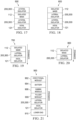
- FIG. 17 a schematic illustration of a second example embodiment of a tool string, generally designated 500 , is shown.
- the tool string 500 includes an isolated mass 112 disposed in series between at least two lateral isolators 200 , 300.
- An axial isolator 121 is disposed serially along the tool string 500 , axially beyond the at least two lateral isolators 200 , 300 .
- the tool string 600 includes at least two lateral isolators 200 , 300 , which are disposed between an isolated mass 112 and an axial isolator 121.
- the tool string 700 includes a single lateral isolator 200 , 300 disposed between an isolated mass 112 and an axial isolator 121.
- the tool string 800 includes a single lateral isolator 200 , 300 disposed below (e.g., in the direction of the drill bit 106 , see Figure 1 ) an isolated mass 112. In some such embodiments, the tool string 800 does not comprise an axial isolator.
- the tool string 900 includes a directional module 902 , a battery 904 , a gamma module 906 , a pulser module 908 , a lateral isolator 200 , 300 , an axial isolator 121 , and a lower end 910 , disposed in the order listed and ending with the lower end being the component of the tool string that is closest to the drill bit (see, e.g., 106 , Figure 1 ).
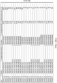
- Runs 10, 11, and 15 were measured at the gamma module 906. Runs 10 and 11 were obtained in a tool string having a standard axial isolator, while Run 15 was obtained in a tool string having a finned axial isolator 121 and lateral isolator 200, 300. Overall, the goal of reducing lateral shock and vibration in this series of run data was achieved.
- the tools performed as expected and showed a direct correlation of reducing lateral shock and vibration when a lateral isolator 200 , 300 and finned axial isolator 121 were paired together in a tool string.
- the finned axial isolator 121 provided a stabilized lower end 910 , while the lateral isolator 200 , 300 decoupled shock inputs at the lower end 910 from the remainder of the components of the tool string 900.
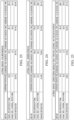
- run data obtained from the directional module 902 is shown.
- the run data showed an average shock reduction of approximately 10%.
- the shock isolation and reduction characteristics are more attenuated (e.g., less) at the directional module 902 due to the lower overall shock inputs.
- there was less run data on the directional module 902 so conclusions are not as defined as the gamma module 906 and pulser module 908 run data shows in Figures 23 and 24 .
- a lateral isolator 200 , 300 can be provided by a drill string level component and/or a tool string level component to reduce the transmission of lateral shocks along, and to other components of, a drill string and/or a tool string by similarly providing one or more components with a mechanism comprising at least an inner member 210 and a tubeform assembly 212.
Landscapes
- Engineering & Computer Science (AREA)
- Life Sciences & Earth Sciences (AREA)
- Geology (AREA)
- Mining & Mineral Resources (AREA)
- Physics & Mathematics (AREA)
- Environmental & Geological Engineering (AREA)
- Fluid Mechanics (AREA)
- General Life Sciences & Earth Sciences (AREA)
- Geochemistry & Mineralogy (AREA)
- Mechanical Engineering (AREA)
- Geophysics (AREA)
- Earth Drilling (AREA)
Description
- The subject matter disclosed herein relates to the design and operation of vibration isolation systems for environments subject to shocks and vibrations, such as downhole operations.
- In some hydrocarbon recovery systems and/or downhole systems, electronics and/or other sensitive hardware (e.g., sometimes referred to as a tool string) may be included in a drill string. In some cases, a drill string may be exposed to both repetitive vibrations including a relatively consistent frequency and to vibratory shocks that may not be repetitive. Each of the repetitive vibrations and shock vibrations may damage and/or otherwise interfere with the operation of the electronics, such as, but not limited to, measurement while drilling (MWD) devices and/or logging while drilling (LWD) devices, and/or any other vibration-sensitive device of a drill string. Some electronic devices are packaged in vibration resistant housings that are not capable of protecting the electronic devices against both the repetitive and shock vibrations. Active vibration isolation systems can isolate the electronics from harmful vibration but at added expense.
US2795398 discloses a shock absorbing drill collar device consisting of two tubular members. Arranged between the two tubular members is a rubber member which is vulcanized to the adjacent walls of the tubular members.US2016/0201413 relates to an off-bottom flow diverter assembly.US3522641 describes a joint alignment device.US2003/189337 describes a fluid coupling device employing a male spherical member with a fluid receiving bore and a female housing. - A lateral isolator is provided as defined in appended claim 1. The lateral isolator comprises: a housing comprising an upstream end and a downstream end; an inner member comprising a pivot ring disposed within the housing; a first elastomeric package disposed between the housing and the inner member, at a position longitudinally between the pivot ring and the upstream end; and a second elastomeric package disposed between the housing and the inner member, at a position longitudinally between the pivot ring and the downstream end.
- The lateral isolator comprises a centralizer sub attached at the upstream end of the housing, the centralizer sub comprising a plurality of compliant fins attached to an outer surface of the centralizer sub and being spaced radially apart from each other about a longitudinal central axis of the lateral isolator.
- In some embodiments of the lateral isolator, the first elastomeric package and the second elastomeric package are configured to collectively respond to a first input force frequency range, wherein the plurality of compliant fins are configured to collectively respond to a second input force frequency range, and wherein the second input force frequency range is different than first input force frequency range.
- In some embodiments of the lateral isolator, each of the compliant fins is configured such that, when a first compliant fin of the compliant fins is radially compressed, an area of an outer face of the compliant fin, which is in contact with a structure in which the lateral isolator is positioned increases to provide a nonlinear stiffening force to the lateral isolator.
- In some embodiments of the lateral isolator, when the lateral isolator is disposed in a wellbore, the lateral isolator maintains a lateral isolator pressure column through a central bore of the lateral isolator that is pressure independent from a mud flow pressure column between an exterior of the lateral isolator and the wellbore.
- In some embodiments of the lateral isolator, when an input force is laterally applied to the inner member in a first direction, the lateral isolator is configured such that a first reaction force opposing the input force is reacted through the first elastomeric package, a second reaction force for opposing the first reaction force is reacted through the second elastomeric package, and a fin force opposing the input force is reacted through at least one of the compliant fins.
- In some embodiments of the lateral isolator, the first and second elastomeric packages are pre-compressed in an axial direction.
- In some embodiments of the lateral isolator, the first and second elastomeric packages are configured to bulge and bulk load.
- In some embodiments of the lateral isolator, the bulk loading is in response to a cocking movement of the inner member about the pivot ring, and wherein the bulk loading provides a soft snub rather than a direct contact.
- The pivot ring comprises a polygonal profile complimentary to a polygonal profile provided within the housing, and wherein the polygonal profiles of the pivot ring and the housing are configured to provide torsional locking between the inner member and the housing.
- In some embodiments of the lateral isolator, the elastomeric packages are configured such that the inner member is rotatably displaceable relative to the body.
- For a more complete understanding of the present disclosure and the advantages thereof, reference is now made to the following brief description, taken in connection with the accompanying drawings and detailed description.
-
Figure 1 is a side view of an example hydrocarbon recovery system comprising an example embodiment of a drill string with lateral isolators according to a first example embodiment disclosed herein. -
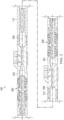
Figure 2 is a cross-sectional view of a portion of the hydrocarbon recovery system ofFigure 1 , showing the lateral isolators in greater detail. -
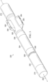
Figure 3 is an oblique view of one of the lateral isolators ofFigure 1 . -
Figure 4 is an oblique exploded view of the lateral isolator ofFigure 3 . -
Figure 5 is a top view of the lateral isolator ofFigure 3 . -
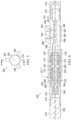
Figure 6 is a cross-sectional side view of the lateral isolator ofFigure 3 , taken along cutting line 6-6 ofFigure 5 . -
Figure 7 is a detailed cross-sectional view of the lateral isolator ofFigure 6 . -
Figure 8 is a cross-sectional view of the lateral isolator ofFigure 6 in a perturbed state. -
Figure 9 is detailed cross-sectional view of the lateral isolator ofFigure 8 . -
Figure 10 is a partial internal end view of the lateral isolator ofFigure 3 . -
Figure 11 is a schematic representation of the lateral isolator ofFigure 3 . -
Figure 12 is a simplified force reaction diagram of the lateral isolator ofFigure 3 . -
Figure 13 is an oblique view of a second example embodiment of a lateral isolator. -
Figure 14 is an oblique exploded view of the lateral isolator ofFigure 13 . -
Figure 15 is a top view of the lateral isolator ofFigure 13 . -
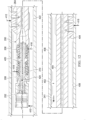
Figure 16 is a cross-sectional side view of the lateral isolator ofFigure 13 , taken along cutting line 16-16 ofFigure 15 . -
Figure 17 is a simplified representation of a second example embodiment of a tool string arrangement according to this disclosure. -
Figure 18 is a simplified representation of a third example embodiment of a tool string arrangement according to this disclosure. -
Figure 19 is a simplified representation of a fourth example embodiment of a tool string arrangement according to this disclosure. -
Figure 20 is a simplified representation of a fifth example embodiment of a tool string arrangement according to this disclosure. -
Figure 21 is a simplified representation of a sixth example embodiment of a tool string arrangement according to this disclosure. -
Figure 22 is a graph of run data obtained when operating the tool string ofFigure 21 . -
Figure 23 is a chart of run data obtained from a pulser module of the tool string ofFigure 21 . -
Figure 24 is a chart of run data obtained from a gamma module of the tool string ofFigure 21 . -
Figure 25 is a chart of run data obtained from a directional module of the tool string ofFigure 21 . -
Figures 26A and26B are charts of detailed shock values, counts, and reductions by run of the tool string ofFigure 21 . - Referring now to
Figure 1 , an example embodiment of a hydrocarbon recovery system (HRS), generally designated 100, is shown. Although theHRS 100 is shown as being onshore (e.g., on land), in alternative embodiments, the HRS 100 can be installed in an offshore location (e.g., at sea). TheHRS 100 generally includes a drill string, generally designated 102 suspended within a borehole, generally designated 104. Theborehole 104 extends substantially vertically away from the earth's surface over a vertical wellbore portion or, in some embodiments, deviates at any suitable angle from the earth's surface over a deviated or horizontal wellbore portion. In alternative operating environments, portions or substantially all of aborehole 104 may be vertical, deviated, horizontal, curved, and/or combinations thereof. - The
drill string 102 includes a drill bit 106 at alower end 103 of thedrill string 102 and a universal bottom hole orienting (UBHO)sub 108 connected above the drill bit 106. The UBHOsub 108 includes amule shoe 110 configured to connect with a stinger orpulser helix 111 on a top side, generally designated 105, of themule shoe 110. TheHRS 100 further includes anelectronics casing 113 incorporated within thedrill string 102 above the UBHOsub 108, for example, connected to a top side, generally designated 107, of the UBHOsub 108. Theelectronics casing 113 may at least partially house the stinger orpulser helix 111, alateral isolator 200 connected above the stinger orpulser helix 111, anisolated mass 112 connected above thelateral isolator 200, alateral isolator 200 connected above the isolatedmass 112, and/orcentralizers 115. Theisolated mass 112 can include electronic components. TheHRS 100 includes a platform and derrick assembly, generally designated 114, positioned over the borehole 104 at the surface. The platform andderrick assembly 114 includes a rotary table 116, which engages akelly 118 at an upper end, generally designated 109, of thedrill string 102 to impart rotation to thedrill string 102. Thedrill string 102 is suspended from ahook 120 that is attached to a traveling block. Thedrill string 102 is positioned through thekelly 118 and therotary swivel 122 which permits rotation of thedrill string 102 relative to thehook 120. Additionally, or alternatively, a top drive system may be used to impart rotation to thedrill string 102. - The
HRS 100 further includesdrilling fluid 124 which may include a water-based mud, an oil-based mud, a gaseous drilling fluid, water, brine, gas, and/or any other suitable fluid for maintaining bore pressure and/or removing cuttings from the area surrounding the drill bit 106. Some volume ofdrilling fluid 124 may be stored in a pit, generally designated 126, and apump 128 may deliver thedrilling fluid 124 to the interior of thedrill string 102 via a port in therotary swivel 122, causing thedrilling fluid 124 to flow downwardly through thedrill string 102, as indicated bydirectional arrow 130. Thedrilling fluid 124 may pass through anannular space 131 between the electronics casing 113 and each of thepulser helix 111, thelateral isolator 200, and/or theisolated mass 112 prior to exiting theUBHO sub 108. After exiting theUBHO sub 108, thedrilling fluid 124 may exit thedrill string 102 via ports in the drill bit 106 and be circulated upwardly through anannulus region 135 between the outside of thedrill string 102 and awall 137 of theborehole 104, as indicated bydirectional arrows 132. Thedrilling fluid 124 may lubricate the drill bit 106, carry cuttings from the within theborehole 104 up to the surface as thedrilling fluid 124 is returned to thepit 126 for recirculation and/or reuse, and/or create a mudcake layer (e.g., filter cake) on thewalls 137 of theborehole 104. - The drill bit 106 may generate vibratory forces and/or shock forces in response to encountering hard formations during the drilling operation. Although the drill bit 106 itself can be considered an
excitation source 117 that provides some vibratory excitation to thedrill string 102, theHRS 100 may further include anexcitation source 117 such as anaxial excitation tool 119 and/or any other vibratory device configured to agitate, vibrate, shake, and/or otherwise change a position of an end of thedrill string 102 and/or any other component of thedrill string 102 relative to thewall 137 of theborehole 104. In some cases, operation of such anaxial excitation tool 119 may generate oscillatory movement of selected portions of thedrill string 102, so that thedrill string 102 is less likely to become hung or otherwise prevented from advancing into and/or out of theborehole 104. In some embodiments, low frequency oscillations of one ormore excitation sources 117 may have values of about 5Hz to about 100Hz, inclusive. Theterm excitation source 117 is intended to refer to any source of the vibratory or shock forces described herein, including, but not limited to, a drill bit 106, anaxial excitation tool 119 that is purpose built to generate such forces, and/or combinations thereof. It will further be appreciated that drill bit whirl and stick slip are also primary sources of lateral shock and vibration and, hence, can also be primary sources of such lateral shock and vibration inputs. - In the embodiment of
Figure 1 , theHRS 100 further includes acommunications relay 134 and a logging andcontrol processor 136. The communications relay 134 may receive information and/or data from sensors, transmitters, receivers, and/or other communicating devices that may form a portion of theisolated mass 112. In some embodiments, the information is received by the communications relay 134 via a wired communication path through thedrill string 102. In other embodiments, the information is received by the communications relay 134 via a wireless communication path. In some embodiments, the communications relay 134 transmits the received information and/or data to the logging andcontrol processor 136. Additionally, or alternatively, the communications relay 134 can receive data and/or information from the logging andcontrol processor 136. In some embodiments, upon receiving the data and/or information, the communications relay 134 forwards the data and/or information to the appropriate sensor(s), transmitter(s), receiver(s), and/or other communicating devices. Theisolated mass 112 may include measuring while drilling (MWD) devices and/or logging while drilling (LWD) devices and theisolated mass 112 may include multiple tools or subs and/or a single tool and/or sub. In the embodiment ofFigure 1 , thedrill string 102 includes a plurality of tubing sections; that is, thedrill string 102 is a jointed or segmented string. Alternative embodiments ofdrill string 102 can include any other suitable conveyance type, for example, coiled tubing, wireline, and/or wired drill pipe. TheHRSs 100 that implement at least one embodiment of alateral isolator 200 and/or lateral isolator 300 (see, e.g.,Figures 13 to 16 ) disclosed herein may be referred to as downhole systems for isolating a component, (e.g., for isolating lateral and/or axial forces to an isolated mass 112). Further, while thelateral isolator 200 and/orlateral isolator 300 disclosed herein may provide some nominal amount of axial isolation, most uses of suchlateral isolators axial isolator 121 disposed in series with thelateral isolators drill string 102, and/or along a tool string that comprises a portion of (e.g., is installed within and/or in-line with) a drill string, such asdrill string 102. - Referring generally to
Figures 2 through 10 , thelateral isolator 200 generally defines a longitudinally-extendingflowbore 201 and has acentral axis 202 with respect to which many of the components of thelateral isolator 200 are substantially coaxially aligned, when in a non-deflected state. Thelateral isolator 200 generally includes atubular housing 204, acentralizer sub 206 connected to thehousing 204 at a first end of thehousing 204, and ahousing cap 208 connected to thehousing 204 at a second end of thehousing 204. Thehousing 204 is configured to receive portions of an inner member, generally designated 210, and two tubeform assemblies, generally designated 212. In the example embodiment shown, thehousing 204 comprises an interiorcircumferential shoulder 214. A first of the twotubeform assemblies 212 can be, or is, retained longitudinally between theshoulder 214 and thehousing cap 208. A second of the twotubeform assemblies 212 can be, or is, retained longitudinally between theshoulder 214 and thecentralizer sub 206. - Referring primarily to
Figures 4 ,6 , and7 , theinner member 210 is generally a tubular structure having a firsttubular portion 216, a secondtubular portion 218, and atubular pivot ring 220, which is connected between the firsttubular portion 216 and the secondtubular portion 218. The firsttubular portion 216 comprises an outer diameter that is substantially similar to an outer diameter of the secondtubular portion 218. The firsttubular portion 216 is longer than the secondtubular portion 218. Thepivot ring 220 comprises a generally polygonalexterior profile 222, which is shaped, in the example embodiment shown, as a hexagonal profile having sixsides 224 when viewed from above or below (e.g., along the central axis 202). Thesides 224 each comprise curvedouter surfaces 226 that are configured to contact aninterior shoulder surface 228 of theshoulder 214. Further, theinterior shoulder surface 228 comprises ashoulder profile 230 that is complementary to the polygonalexterior profile 222 of theinner member 210. Accordingly, when thepivot ring 220 is received within thehousing 204 and, more specifically, longitudinally within theshoulder 214 and in contact with theinterior shoulder surface 228, theinner member 210 is prevented from rotating angularly about thecentral axis 202 relative to thehousing 204. While the polygonalexterior profile 222 and theinterior shoulder surface 228 each have generally hexagonal profiles, in alternative embodiments, theinterior shoulder surface 228 and the polygonalexterior profile 222 can comprise any other suitable complementary shapes that, when nested together, similarly prevent relative angular rotation between theinner member 210 and thehousing 204 about thecentral axis 202, while allowing the relative movements of theinner member 210 relative to thehousing 204 described elsewhere herein. It will be appreciated that the polygonalexterior profile 222 can be provided, in some embodiments, as having more or fewer than six sides, such as, but not limited to, pentagonal or octagonal shapes. - Even though the polygonal
exterior profiles 222 described herein prevent relative angular movement (e.g., rotation) of theinner member 210 relative to thehousing 204 about thecentral axis 202, theinner member 210 is allowed to move both longitudinally relative to thehousing 204 and/or in a pivoting or cocking motion relative to thehousing 204. The pivoting or cocking motion can allow, in some example embodiments, for up to and/or at least 1.5 degrees of relative deviation between an inner membercentral axis 225 of theinner member 210 and thecentral axis 202, as shown inFigures 8 and9 . The amount of relative movement allowed between theinner member 210 and thehousing 204 is limited by the presence of thetubeform assemblies 212. Different amounts of relative angular deviation, both greater and smaller, between the inner membercentral axis 225 and thecentral axis 225 may be provided from the example value of 1.5 degrees provided herein. - Referring primarily to
Figure 7 , eachtubeform assembly 212 comprises aninner retainer 232, anouter retainer 234,elastomeric package 236 disposed at least partially between theinner retainer 232 and theouter retainer 234, and anend ring 238. Theinner retainer 232 is generally tubular (e.g., in the shape of a hollow cylinder) in shape and includes acentral portion 240 comprising a substantially constant inner diameter suitable for receiving the secondtubular portion 218 of theinner member 210. Theinner retainer 232 includes a capturedlip 242 disposed at a first end of thecentral portion 240. The capturedlip 242 has an inner diameter substantially similar to the inner diameter of thecentral portion 240, but has an outer diameter that is larger than an outer diameter of thecentral portion 240. Theinner retainer 232 also includes a flaredend portion 244 disposed at a second end of thecentral portion 240. The flaredend portion 244 has a flared or gradually increasing inner diameter and an external diameter larger than the external diameter of the capturedlip 242. - The
outer retainer 234 includes acentral portion 246 having an outer diameter suitable for being received within theshoulder 214 ofhousing 204. Theouter retainer 234 also has aninward abutment ring 248 disposed at a first end of thecentral portion 246 and anouter abutment ring 250 disposed at a second end of thecentral portion 246. Theinward abutment ring 248 has an outer diameter substantially the same as the outer diameter of thecentral portion 246 but has an inner diameter that is smaller than the inner diameter of thecentral portion 246. Theouter abutment ring 250 has an inner diameter substantially the same as the inner diameter of thecentral portion 246 but has an outer diameter that is larger than the outer diameter of thecentral portion 246. - The
elastomeric package 236 is disposed, at least partially, in a space radially betweeninner retainer 232 andouter retainer 234. Theelastomeric package 236 is also disposed, at least partially, in a space longitudinally between the flaredend portion 244 and theinward abutment ring 248. Further, theelastomeric package 236 is disposed, at least partially, in a space radially between theinner retainer 232 and thehousing cap 208. A portion of theelastomeric package 236 is also disposed, at least partially, longitudinally between the capturedlip 242 and theend ring 238. Theend ring 238 has an inner diameter configured to receive (e.g., the same size, or larger than) the firsttubular portion 216 and an outer diameter that is smaller than than an inner diameter of thehousing cap 208. In this embodiment, a portion of theelastomeric package 236 is disposed radially between theend ring 238 and thehousing cap 208. Because theelastomeric package 236 is elastically deformable, theinner member 210 is movable relative to thehousing 204 as a function of deforming theelastomeric package 236, but the movement of theinner member 210 relative to thehousing 204 is limited by the limited compressibility of the elastomeric material of theelastomeric package 236, as well as the limited amount of free space into which the elastomeric material can be displaced. In this embodiment, thetubeform assemblies 212 are provided so that theelastomeric packages 236 are pre-compressed (e.g., in the axial direction), thereby maintaining a preload on the elastomer that eliminates gapping and reduces the effects of compression set. Under extreme axial loads applied to thetubeform assemblies 212, the elastomer of theelastomeric packages 236 is allowed to bulge and fill free volume within the surrounding structure so that the elastomeric material bulk loads to control an amount of shear within the elastomeric material. This can be particularly useful when the elastomeric material comprises rubber. - Referring primarily to
Figure 6 , the firsttubular portion 216 of theinner member 210 is connected to amovable sub 252. Themovable sub 252 is configured to receive a reducedneck portion 254 of thefirst tube portion 216 and asub nut 256 is received within themovable sub 252 and configured to threadingly engage the reducedneck portion 254, thereby capturing themovable sub 252 relative to theinner member 210 and ensuring that movement of theinner member 210 causes similar movement to themovable sub 252 and vice versa. The reducedneck portion 254 is a distal portion of the firsttubular portion 216 having a reduced outer diameter as compared to the proximal portion of the firsttubular portion 216, the proximal portion of the firsttubular portion 216 being adjacent to and/or in contact with thepivot ring 220. Thehousing cap 208 comprises abowl profile 258 configured to receive aguide neck 260 of themovable sub 252, theguide neck 260 having an outer profile generally complementary to thebowl profile 258. In this embodiment, at least a portion of theguide neck 260 remains received longitudinally within thehousing cap 208, thereby ensuring that relative longitudinal movement of theinner member 210 relative to thehousing 204 does not result in themovable sub 252 becoming hung on an uninclined surface (e.g., a flat end surface) of thehousing cap 208. Also, thebowl profile 258 and theguide neck 260 have substantially similar contoured contact surfaces to work together to prevent excess or harmful cocking deviation of theinner member 210 relative to thehousing 204. - Still referring primarily to
Figure 6 , thecentralizer sub 206 extends away from the housing 204 (e.g., in the direction of the central axis 202) and comprises acarrier portion 262 comprising an outer diameter that is reduced, or smaller, compared to the outer diameter of thehousing 204 and/or other portions of thecentralizer sub 206. Thecentralizer sub 206 further comprisescompliant fins 264 carried by (e.g., rigidly attached to) thecarrier portion 262. In the example embodiment shown, thecentralizer sub 206 includes threecompliant fins 264 disposed about thecentral axis 202 in an evenly distributed angular array (e.g., spaced apart from each other with an angular pitch of about 120 degrees). Thecompliant fins 264 are configured for a directional installation relative to anticipated fluid flow along the exterior of thelateral isolator 200. More specifically, eachcompliant fin 264 includes adownstream incline surface 266 that gradually decreases an outer diameter of thecompliant fin 264 along the longitudinal length of thecompliant fin 264 in the direction of fluid flow 261. In contrast, a relatively blunt upstream incline surface 268 (e.g., having a larger angle relative to thecentral axis 202 than the downstream incline surface 266) of thecompliant fin 264 is provided. In this embodiment, thecompliant fins 264 are constructed at least partially of elastomeric material, so that thelateral isolator 200 provides additional lateral and/or cocking compliance beyond the features disclosed elsewhere herein. Thecompliant fin 264 shape provides a varying load area that changes with respect to the amount of force on theface 263. Under small loads, theface 263 has a smaller load area when compared to large loads. Theface 263 can bulge to enable the non-linear stiffness behavior of thecompliant fin 264. As thecompliant fin 264 is compressed radially, the surface area of theface 263 acting as a contact surface will increase due to the radial compression of thecompliant fin 264, thereby providing the varying, or variable, load area referenced herein. - Still referring primarily to
Figure 6 , thelateral isolator 200 is shown with an optionalmovable sub protector 270, which is threadingly engaged to themovable sub 252, and an optionalcentralizer sub protector 272, which is threadingly engaged to thecentralizer sub 206. Themovable sub protector 270 and thecentralizer sub protector 272 can be provided on thelateral isolator 200 to protect theinternal connection threads 274 of themovable sub 252 and theexternal connection threads 276 of thecentralizer sub 206, respectively, when thelateral isolator 200 is not yet installed within thedrill string 102 of anHRS 100. - Referring now to
Figure 10 , a longitudinal end view of theinner member 210 is shown disposed withinhousing 204, with some components of thelateral isolator 200 being omitted from this view. The polygonalexterior profile 222 ofinner member 210 is matched by (e.g., has an outer surface that is substantially the same size and shape as the outer surface of) a complimentarypolygonal profile 223 ofhousing 204. - Referring now to
Figure 11 , a simplified schematic representation of thelateral isolator 200 can be described more generally as a series spring/damper system where the elastomeric components, theelastomeric packages 236 and thecompliant fins 264, provide both spring and damping characteristics to thelateral isolator 200. More specifically, thelateral isolator 200 is shown with kinematic connections between the unitary combination of thehousing 204,centralizer sub 206, and housing cap 208 (labeled collectively as "ISOLATOR BODY" inFigure 11 ) and each of theinner member 210 and the movable sub 252 (labeled as "DRILL COLLAR" inFigure 11 ), these kinematic connections being the elastomeric package(s) 236 and thecompliant fins 264, respectively. Theelastomeric packages 236 are shown as having aspring force component 213 and a dampingforce component 215. Thecompliant fins 264 are shown as having aspring force component 265 and a dampingforce component 267. Because thelateral isolator 200 comprises two unique sets of elastomeric components, theelastomeric packages 236 and thecompliant fins 264, thelateral isolator 200 can be referred to as a dual stage isolator. - Dual stage isolation can be provided by the
lateral isolator 200 by tuning the two different sets of elastomeric components to any of a variety of performance characteristics, such as, for example, by selecting optimized stiffness and damping characteristics. For example, the dual stage isolation can be achieved by providingelastomeric packages 236 that are softer (e.g., have lower stiffness values) than thecompliant fins 264, which can be harder, or stiffer, than theelastomeric packages 236. Alternatively, the dual stage isolation can be achieved by providingcompliant fins 264 that are softer (e.g., have lower stiffness values) than the set ofelastomeric packages 236, which can be harder, or stiffer, than thecompliant fins 264. These arrangements allow for higher displacement under an aggressive, or large magnitude, force input and boostslateral isolator 200 performance by more effectively mitigating shock by extending the duration of the input into thelateral isolator 200 system occurs. In some embodiments, stiffness ofcompliant fins 264 can be about 210 N/mm (1,200 pounds per inch (lbs/in)) to about 390 N/mm (2,200 lbs/in) to ensure proper operation of the dual stage isolation characteristics of thelateral isolator 200. Of course,compliant fin 264 andelastomeric package 236 stiffness and geometries can be scaled or tailored to be appropriate for applications other than use withHRS 100. In some cases,compliant fins 264 can be replaced by other compliant centralizing components, such as, for example, a drill pipe centralizer. Generally, thelateral isolator 200 can be scaled by using substantially the same design but with changes to material or geometry to satisfy different design constraints, such as larger or smaller ranges of frequency responsiveness or load capability. - The
lateral isolator 200 is designed to be operated, in most circumstances, with an axial isolator, such asaxial isolator 121. Because axial shocks are not to be primarily handled by (e.g., absorbed and/or dissipated by) thelateral isolator 200, thelateral isolator 200 is designed to have a high stiffness rating in the axial direction to limit strain on theelastomeric packages 236, thereby increasing the service life of theelastomeric packages 236. During high amplitude axial input shock events, thetubeform assemblies 212 are configured to allow full bulk loading in a compression region of the elastomer by capturing elastomer between theend ring 238 and the capturedlip 242 and also between the flaredend portion 244 and theinward abutment ring 248. This bulk loading behavior restricts motion and keeps strain levels of theelastomeric packages 236 within acceptable limits. - The
lateral isolator 200 can provide some torsional isolation and shock protection to thedrill string 102 and/or atool string 402 as well. As explained elsewhere herein, theinner member 210,tubeform assemblies 212, and collective isolator body (e.g., thehousing 204, thecentralizer sub 206, and the housing cap 208) are all rotatably interlocked using polygonal profiles to provide torsional compliance through the elastomer region and eliminate motion across hard components. The component sizing tolerances are configured and selected to allow the largest gap to exist between the polygonal profile (e.g., 222) of theinner member 210 and the complimentary polygonal profile (e.g., 223) of thehousing 204 to allow for torsional compliance between the downstream and upstream connections made to thelateral isolator 200. As the center pivot polygon profile (e.g., 222) of thepivot ring 220 wears (e.g., due to frictional contact with adjacent surfaces) during use, the torsional compliance provided by thelateral isolator 200 increases due to wearing of the polygon interface surfaces (e.g., 222, 223), thereby increasing torsional isolation provided by thelateral isolator 200 during the operational life of thelateral isolator 200. - Referring now to
Figure 12 , a simplified force reaction diagram of alateral isolator 200 in use is shown. When in use, thelateral isolator 200 is typically deployed in conjunction with anothertool string component 400 connected in series along the length of thetool string 402. In most applications, thetool string component 400 will comprise acentralizer 404. Thecentralizer 404 can comprise, or be in the shape of, a plurality of radially arranged fins substantially similar tocompliant fins 264 in shape, stiffness, and/or damping characteristics. However, thecentralizer 404 may be shaped differently and may contact aninterior wall 406 of atubular component 408 differently as compared to howcompliant fins 264 contact thetubular component 408. - When the
lateral isolator 200 and thetool string component 400 are deployed within thetubular component 408, a substantiallylateral input force 410 may be introduced (e.g., in a substantially radial direction, relative to the central axis 202) to thelateral isolator 200 at themovable sub 252. Thelateral input force 410 is typically provided to thelateral isolator 200 by a component connected to themovable sub 252 at an opposite end from which theinner member 210 is connected thereto, in series along thetool string 402. Thelateral input force 410 is reacted to by an opposingfin force 412 that represents theinterior wall 406 opposing the radial movement of one morecompliant fins 264 as thecompliant fins 264 are pressed against theinterior wall 406 in response to thelateral input force 410 being transferred through thelateral isolator 200. When the lateral input andfin forces inner member 210 pivots about thepivot ring 220 so as to be inclined, or cocked, relative to the rigid surrounding outer portions, such that the inner membercentral axis 225 is no longer coaxial with, or parallel to, thecentral axis 202, thereby providing lateral bending compliance and preventing the need to accommodate such bending forces as are required to be accommodated in rigidly attached tool string components known from the prior art. - As shown, the lateral bending compliance is achieved by compressing
elastomeric packages 236 between theinner member 210 and at least thehousing cap 208, resulting in adownstream reaction force 414, and between theinner member 210 and at least thecentralizer sub 206, resulting in anupstream reaction force 416. In response to the lateral input andfin forces tool string 402 can be balanced by radial movements of thecentralizer 404 being opposed by contact with theinterior wall 406, thereby generating a balancingforce 418.Figure 12 is also helpful in illustrating that, when thelateral isolator 200 is disposed within the tubular component 408 (e.g., a wellbore), thelateral isolator 200 defines a lateralisolator pressure column 420 longitudinally through the center of thelateral isolator 200 and a separateexterior pressure column 422 that is between the exterior of thelateral isolator 200 and thetubular component 408. The lateralisolator pressure column 420 is pressure independent from theexterior pressure column 422. Further, afluid flow direction 424 within the lateralisolator pressure column 420 is in the same direction as thefluid flow direction 241 of theexterior pressure column 422. - Referring now to
Figures 13 to 16 , a second example embodiment of a lateral isolator, generally designated 300 , is shown. Thelateral isolator 300 is substantially similar tolateral isolator 200, but rather than comprising themovable sub 252 and associatedsub nut 256 shown and described in thelateral isolator 200, thelateral isolator 300 comprises amovable sub 304 and aspanner nut 302, which is disposed between themovable sub 304 and thehousing cap 208. Each of thespanner nut 302 and themovable sub 304 are configured for threadingly engaging with a threaded portion (e.g., a reducedneck portion 254, seeFIG. 6 ) of the firsttubular portion 216 of theinner member 210. - In operation, the
lateral isolators drill string 102. Thelateral isolators drill string 102 whirling compared to conventional rigidly attached and/or assembled drill strings. Providing thelateral isolators drill string 102 in a manner that provides a relatively soft joint that allows cocking and lateral movement between components of thetool string 402 and/or thedrill string 102 attached thereto, as opposed to being rigidly mounted and/or only providing axial vibration and shock reduction. Thelateral isolators lateral isolators centralizer sub 206 and associatedcompliant fins 264 provide thetool string 402 and/or thedrill string 102 stability and control, as well as additional lateral compliance characteristics for thelateral isolators tool string 402 and/or thedrill string 102 increases fatigue life of the system and maintains centralization of the MWD/LWD electronics. - Additionally, because the
lateral isolators HRS 100 may comprise two or more (e.g., a plurality of)lateral isolators drill string 102 and/or thetool string 402. - The
lateral isolators isolated mass 112. When theisolated mass 112 carries battery packs, thelateral isolators lateral isolators isolated mass 112. Further, thelateral isolators lateral isolators isolated mass 112 to survive longer in an aggressive drilling environment, where lateral shock and vibration are larger than in conservative drilling environments. - The
lateral isolators lateral isolators lateral isolators lateral isolators lateral isolators lateral isolators lateral isolators lateral isolators isolated mass 112, or other sensitive electronics of a tool string, thereby enabling improved longevity and reliability of the electronics. Thelateral isolators lateral isolators lateral isolators - Referring now to
Figure 17 , a schematic illustration of a second example embodiment of a tool string, generally designated 500, is shown. Thetool string 500 includes anisolated mass 112 disposed in series between at least twolateral isolators axial isolator 121 is disposed serially along thetool string 500, axially beyond the at least twolateral isolators - Referring now to
Figure 18 , a schematic illustration of a third example embodiment of a tool string, generally designated 600, is shown. Thetool string 600 includes at least twolateral isolators isolated mass 112 and anaxial isolator 121. - Referring now to
Figure 19 , a schematic illustration of a fourth example embodiment of a tool string, generally designated 700, is shown. Thetool string 700 includes a singlelateral isolator isolated mass 112 and anaxial isolator 121. - Referring now to
Figure 20 , a schematic illustration of a fifth example embodiment of a tool string, generally designated 800, is shown. Thetool string 800 includes a singlelateral isolator Figure 1 ) anisolated mass 112. In some such embodiments, thetool string 800 does not comprise an axial isolator. - Referring now to
Figure 21 , a schematic illustration of a sixth example embodiment of a tool string, generally designated 900, is shown. Thetool string 900 includes adirectional module 902, abattery 904, agamma module 906, apulser module 908, alateral isolator axial isolator 121, and alower end 910, disposed in the order listed and ending with the lower end being the component of the tool string that is closest to the drill bit (see, e.g., 106,Figure 1 ). - Referring now to
Figure 22 , a graphical plot of run data during operating thetool string 900 ofFigure 21 is shown. The run data was acquired in a lateral segment in comparable run conditions. Each configuration was run five times, with data pulled from thepulser module 908,gamma module 906, anddirectional module 902. Results showed favorable shock reduction with the greatest reduction being observed in the components along thetool string 900 that are closest to thelateral isolator lateral isolator pulser module 908 and thegamma module 906. It is thought that the enhanced shock reduction observed at thepulser module 908 and thegamma module 906 is due to the close proximity of thelateral isolator tool string 900 that have greater exposure to high (>30 g) shock events typically observed adjacent thelower end 910 of thetool string 900. Thelateral isolator - Data was compiled using the start and end point of the
tool string 900. Runs 10, 11, and 15 were measured at thegamma module 906.Runs Run 15 was obtained in a tool string having a finnedaxial isolator 121 andlateral isolator lateral isolator axial isolator 121 were paired together in a tool string. The finnedaxial isolator 121 provided a stabilizedlower end 910, while thelateral isolator lower end 910 from the remainder of the components of thetool string 900. - Referring now to
Figure 23 , run data obtained from thepulser module 908 is shown. The run data showed an average shock reduction of approximately 30%. However, the shock isolation and reduction benefit is seen in the normalized data for shock counts per hour. Results show approximately an 88% reduction of shock counts greater than 30 g. The results also confirmed that the shock isolation and reduction benefits are realized when higher shock inputs are received. - Referring now to
Figure 24 , run data obtained from thegamma module 906 is shown. The run data showed an average shock reduction of approximately 31%. Like with thepulser module 908 data ofFigure 23 , the shock isolation and reduction benefits are seen in shock counts per hour. Results show approximately a 76% reduction of shock counts greater than 30 g. The results also confirmed that the shock isolation and reduction benefits are realized when higher shock inputs are received. - Referring now to
Figure 25 , run data obtained from thedirectional module 902 is shown. The run data showed an average shock reduction of approximately 10%. The shock isolation and reduction characteristics are more attenuated (e.g., less) at thedirectional module 902 due to the lower overall shock inputs. Also, there was less run data on thedirectional module 902, so conclusions are not as defined as thegamma module 906 andpulser module 908 run data shows inFigures 23 and 24 . - Referring now to
Figures 26A and26B , detailed shock values, counts, and reductions by run of thetool string 900 are provided. - It will be appreciated that the type of isolation provided by a
lateral isolator inner member 210 and atubeform assembly 212. - Other embodiments of the current invention will be apparent to those skilled in the art from a consideration of this specification or practice of the invention disclosed herein. Thus, the foregoing specification is considered merely exemplary of the current invention with the true scope thereof being defined by the following claims.
Claims (15)
- A lateral isolator (200, 300) comprising:a tubular housing (204) comprising:an upstream end;a downstream end; andan interior circumferential shoulder (214) comprising an interior shoulder surface (228), which has a shoulder profile (230);an inner member (210) comprising:a first tubular portion (216);a second tubular portion (218); anda pivot ring (220) disposed within the housing (204),
wherein the pivot ring (220) is connected between the first tubular portion (216) and the second tubular portion (218); andwherein the pivot ring (220) comprises a polygonal profile (222) complimentary to the shoulder profile (230), the polygonal profile (222) of the pivot ring (220) and the shoulder profile (230) of the housing (204) being configured to provide torsional locking between the inner member (210) and the housing (204);a centralizer sub (206) connected to the housing (204) at the upstream end of the housing (204), the centralizer sub (206) comprising a plurality of compliant fins (264) attached to an outer surface of the centralizer sub (206) and being spaced radially apart from each other about a longitudinal central axis (202) of the lateral isolator (200, 300);a housing cap (208) connected to the housing (204) at the downstream end of the housing (204), the housing cap (208) comprising a bowl profile (258) configured to receive a guide neck (260) of a movable sub (252), the guide neck (260) having an outer profile complementary to the bowl profile (258);a first elastomeric package (236) disposed between the housing (204) and the inner member (210), at a position longitudinally between the pivot ring (220) and the housing cap (208); anda second elastomeric package (236) disposed between the housing (204) and the inner member (210), at a position longitudinally between the pivot ring (220) and the centralizer sub (206). - The lateral isolator (200, 300) of claim 1, wherein the first elastomeric package (236) and the second elastomeric package (236) are configured to collectively respond to a first input force frequency range, wherein the plurality of compliant fins (264) are configured to collectively respond to a second input force frequency range, and wherein the second input force frequency range is different than first input force frequency range.
- The lateral isolator (200, 300) of claim 1, wherein each of the compliant fins (264) is configured such that, when a first compliant fin (264) of the compliant fins (264) is radially compressed, an area of an outer face of the compliant fin (264), which is in contact with a structure in which the lateral isolator (200, 300) is positioned increases to provide a nonlinear stiffening force to the lateral isolator (200, 300).
- The lateral isolator (200, 300) of claim 1, wherein, when the lateral isolator (200, 300) is disposed in a wellbore, the lateral isolator (200, 300) maintains a lateral isolator pressure column through a central bore of the lateral isolator (200, 300) that is pressure independent from a mud flow pressure column between an exterior of the lateral isolator (200, 300) and the wellbore.
- The lateral isolator (200, 300) of claim 4, wherein, when an input force is laterally applied to the inner member (210) in a first direction, the lateral isolator (200, 300) is configured such that a first reaction force (416) opposing the input force (410) is reacted through the first elastomeric package (236), a second reaction force (414) for opposing the first reaction force (416) is reacted through the second elastomeric package (236), and a fin force (412) opposing the input force (410) is reacted through at least one of the compliant fins (264).
- The lateral isolator (200, 300) of claim 1, wherein the first and second elastomeric packages (236) are pre-compressed in an axial direction.
- The lateral isolator (200, 300) of claim 1, wherein the first and second elastomeric packages (236) are configured to bulge and bulk load.
- The lateral isolator (200, 300) of claim 7, wherein the bulk loading is in response to a cocking movement of the inner member (210) about the pivot ring (220), and wherein the bulk loading provides a soft snub rather than a direct contact.
- The lateral isolator (200, 300) of claim 1, wherein the first and second elastomeric packages (236) are configured such that the inner member (210) is rotatably displaceable relative to the tubular housing (204).
- The lateral isolator (200, 300) of claim 1, comprising:a first tubeform assembly (212) comprising:an inner retainer (232);an outer retainer (234);the first elastomeric package (236), which is disposed at least partially between the inner retainer (232) and the outer retainer (234); andan end ring (238);wherein the first tubeform assembly (212) is retained longitudinally between the shoulder (214) and the housing cap (208); anda second tubeform assembly, comprising:an inner retainer (232);an outer retainer (234);the first elastomeric package (236), which is disposed at least partially between the inner retainer (232) and the outer retainer (234); andan end ring (238);wherein the second tubeform assembly (212) is retained longitudinally between the shoulder (214) and the centralizer sub (206).
- The lateral isolator (200, 300) of claim 10, wherein the housing is configured to receive portions of the inner member (210) and the first and second tubeform members (212, 212).
- The lateral isolator (200, 300) of claim 10 or 11, wherein the inner retainer (232) of each of the first and second tubeform assemblies (212, 212) is generally tubular in shape and includes a central portion (240) comprising a substantially constant inner diameter.
- The lateral isolator (200, 300) of any of claims 10-12, wherein the outer retainer (234) of each of the first and second tubeform assemblies (212, 212) has an outer diameter suitable for being received within the shoulder (214) of the tubular housing (204).
- The lateral isolator (200, 300) of any of claims 10-13, wherein:the first tubular portion (216) comprises an outer diameter that is substantially similar to an outer diameter of the second tubular portion (218); andthe first tubular portion (216) is longer than the second tubular portion (218).
- The lateral isolator (200, 300) of any of claims 10-14, wherein:the first tubular portion (216) of the inner member (210) passes through the inner retainer (232) of the first tubeform assembly (212); andthe second tubular portion (218) of the inner member (210) passes through the inner retainer (232) of the second tubeform assembly (212).
Applications Claiming Priority (2)
| Application Number | Priority Date | Filing Date | Title |
|---|---|---|---|
| US201962827369P | 2019-04-01 | 2019-04-01 | |
| PCT/US2020/020901 WO2020205138A1 (en) | 2019-04-01 | 2020-03-04 | Lateral isolator |
Publications (2)
| Publication Number | Publication Date |
|---|---|
| EP3947893A1 EP3947893A1 (en) | 2022-02-09 |
| EP3947893B1 true EP3947893B1 (en) | 2025-05-07 |
Family
ID=70058501
Family Applications (1)
| Application Number | Title | Priority Date | Filing Date |
|---|---|---|---|
| EP20716039.1A Active EP3947893B1 (en) | 2019-04-01 | 2020-03-04 | Lateral isolator |
Country Status (3)
| Country | Link |
|---|---|
| US (1) | US11761271B2 (en) |
| EP (1) | EP3947893B1 (en) |
| WO (1) | WO2020205138A1 (en) |
Families Citing this family (5)
| Publication number | Priority date | Publication date | Assignee | Title |
|---|---|---|---|---|
| EP3947893B1 (en) | 2019-04-01 | 2025-05-07 | LORD Corporation | Lateral isolator |
| CA3163099A1 (en) * | 2019-12-21 | 2021-06-24 | Scientific Drilling International, Inc. | Method and apparatus for damping/absorbing rotational vibrations/oscillations |
| US12006777B2 (en) * | 2021-07-29 | 2024-06-11 | Landmark Graphics Corporation | Multiple swivels and rotation motor system |
| US11846142B2 (en) * | 2022-05-16 | 2023-12-19 | China Petroleum & Chemical Corporation | Interconnect for downhole instruments |
| WO2025006689A2 (en) * | 2023-06-29 | 2025-01-02 | Turbo Drill Industries, Inc. | Mwd isolation device |
Citations (2)
| Publication number | Priority date | Publication date | Assignee | Title |
|---|---|---|---|---|
| US3522641A (en) * | 1968-10-09 | 1970-08-04 | Leo L Rizzo | Joint alignment device |
| US20030189337A1 (en) * | 2000-11-22 | 2003-10-09 | Strahman Valves, Inc. | Fluid coupling device |
Family Cites Families (19)
| Publication number | Priority date | Publication date | Assignee | Title |
|---|---|---|---|---|
| US2572307A (en) * | 1946-09-09 | 1951-10-23 | Cicero C Brown | Rotary drill stabilizer |
| US2795398A (en) * | 1954-03-25 | 1957-06-11 | Exxon Research Engineering Co | Shock absorbing drill collar |
| US3606392A (en) * | 1969-04-14 | 1971-09-20 | Smith Ind International Inc | Vibration dampener |
| US3593797A (en) * | 1969-05-16 | 1971-07-20 | Schlumberger Technology Corp | Method and apparatus for consolidating a subsurface earth formation |
| FR2058451A5 (en) * | 1969-09-05 | 1971-05-28 | Aquitaine Petrole | |
| US4630809A (en) * | 1985-05-13 | 1986-12-23 | Teleco Oilfield Services Inc. | Vibration isolator and shock absorber device |
| US4823125A (en) * | 1987-06-30 | 1989-04-18 | Develco, Inc. | Method and apparatus for stabilizing a communication sensor in a borehole |
| US9334698B2 (en) * | 2011-06-28 | 2016-05-10 | Utah Valley University | Drill rod shock tool |
| US9869135B1 (en) * | 2012-06-21 | 2018-01-16 | Rfg Technology Partners Llc | Sucker rod apparatus and methods for manufacture and use |
| US20140370995A1 (en) * | 2012-12-26 | 2014-12-18 | Ge Oil & Gas Esp, Inc. | Flexible joint connection |
| US20150218938A1 (en) * | 2014-01-31 | 2015-08-06 | Weatherford/Lamb, Inc. | Hard-Mounted EM Telemetry System for MWD Tool in Bottom Hole Assembly |
| WO2015171176A1 (en) * | 2014-05-05 | 2015-11-12 | Lord Corporation | Mud motor transmission |
| US9435166B2 (en) * | 2014-05-06 | 2016-09-06 | Ge Energy Oilfield Technology, Inc. | Method for aligning MWD tool using orienting hanger assembly |
| US9932788B2 (en) * | 2015-01-14 | 2018-04-03 | Epiroc Drilling Tools Llc | Off bottom flow diverter sub |
| US10480260B2 (en) * | 2015-06-30 | 2019-11-19 | Lord Corporation | Isolator |
| US10934778B2 (en) * | 2016-09-30 | 2021-03-02 | Abaco Drilling Technologies, LLC | BHA transmission with laminated rubber bearings |
| GB2583249B (en) * | 2018-01-05 | 2022-05-11 | Petromac Ip Ltd | A guide device |
| WO2020180926A1 (en) * | 2019-03-04 | 2020-09-10 | Lord Corporation | Centralizer |
| EP3947893B1 (en) | 2019-04-01 | 2025-05-07 | LORD Corporation | Lateral isolator |
-
2020
- 2020-03-04 EP EP20716039.1A patent/EP3947893B1/en active Active
- 2020-03-04 US US17/598,966 patent/US11761271B2/en active Active
- 2020-03-04 WO PCT/US2020/020901 patent/WO2020205138A1/en not_active Ceased
Patent Citations (2)
| Publication number | Priority date | Publication date | Assignee | Title |
|---|---|---|---|---|
| US3522641A (en) * | 1968-10-09 | 1970-08-04 | Leo L Rizzo | Joint alignment device |
| US20030189337A1 (en) * | 2000-11-22 | 2003-10-09 | Strahman Valves, Inc. | Fluid coupling device |
Also Published As
| Publication number | Publication date |
|---|---|
| WO2020205138A1 (en) | 2020-10-08 |
| US20220195815A1 (en) | 2022-06-23 |
| US11761271B2 (en) | 2023-09-19 |
| CA3135481A1 (en) | 2020-10-08 |
| EP3947893A1 (en) | 2022-02-09 |
Similar Documents
| Publication | Publication Date | Title |
|---|---|---|
| US11761271B2 (en) | Lateral isolator | |
| CN1890451B (en) | Systems and methods for damping vibrations in a drill string | |
| CN102725475B (en) | For the instrument that the minimizing of down-hole electronic building brick is impacted | |
| US9512684B2 (en) | Shock tool for drillstring | |
| EP3097264B1 (en) | Isolating mule shoe | |
| US10480260B2 (en) | Isolator | |
| CN104685151B (en) | Isolator | |
| US20190119994A1 (en) | Snubber for Downhole Tool | |
| WO2014179587A1 (en) | Torsional isolator | |
| CA3135481C (en) | Lateral isolator | |
| US20240344404A1 (en) | Methods and apparatus for dampening forces acting upon the drill string during drilling of subterranean wells | |
| US20250305374A1 (en) | Hydrostatically-actuatable systems and related methods | |
| Hall et al. | Downhole tool adapted for telemetry | |
| CA2944572A1 (en) | Device for isolating a tool from axial vibration while maintaining conductor connectivity |
Legal Events
| Date | Code | Title | Description |
|---|---|---|---|
| STAA | Information on the status of an ep patent application or granted ep patent |
Free format text: STATUS: UNKNOWN |
|
| STAA | Information on the status of an ep patent application or granted ep patent |
Free format text: STATUS: THE INTERNATIONAL PUBLICATION HAS BEEN MADE |
|
| PUAI | Public reference made under article 153(3) epc to a published international application that has entered the european phase |
Free format text: ORIGINAL CODE: 0009012 |
|
| STAA | Information on the status of an ep patent application or granted ep patent |
Free format text: STATUS: REQUEST FOR EXAMINATION WAS MADE |
|
| 17P | Request for examination filed |
Effective date: 20210929 |
|
| AK | Designated contracting states |
Kind code of ref document: A1 Designated state(s): AL AT BE BG CH CY CZ DE DK EE ES FI FR GB GR HR HU IE IS IT LI LT LU LV MC MK MT NL NO PL PT RO RS SE SI SK SM TR |
|
| DAV | Request for validation of the european patent (deleted) | ||
| DAX | Request for extension of the european patent (deleted) | ||
| STAA | Information on the status of an ep patent application or granted ep patent |
Free format text: STATUS: EXAMINATION IS IN PROGRESS |
|
| 17Q | First examination report despatched |
Effective date: 20230112 |
|
| P01 | Opt-out of the competence of the unified patent court (upc) registered |
Effective date: 20230524 |
|
| RAP3 | Party data changed (applicant data changed or rights of an application transferred) |
Owner name: LORD CORPORATION |
|
| GRAP | Despatch of communication of intention to grant a patent |
Free format text: ORIGINAL CODE: EPIDOSNIGR1 |
|
| STAA | Information on the status of an ep patent application or granted ep patent |
Free format text: STATUS: GRANT OF PATENT IS INTENDED |
|
| INTG | Intention to grant announced |
Effective date: 20241004 |
|
| GRAS | Grant fee paid |
Free format text: ORIGINAL CODE: EPIDOSNIGR3 |
|
| GRAA | (expected) grant |
Free format text: ORIGINAL CODE: 0009210 |
|
| STAA | Information on the status of an ep patent application or granted ep patent |
Free format text: STATUS: THE PATENT HAS BEEN GRANTED |
|
| AK | Designated contracting states |
Kind code of ref document: B1 Designated state(s): AL AT BE BG CH CY CZ DE DK EE ES FI FR GB GR HR HU IE IS IT LI LT LU LV MC MK MT NL NO PL PT RO RS SE SI SK SM TR |
|
| REG | Reference to a national code |
Ref country code: GB Ref legal event code: FG4D |
|
| REG | Reference to a national code |
Ref country code: CH Ref legal event code: EP |
|
| REG | Reference to a national code |
Ref country code: DE Ref legal event code: R096 Ref document number: 602020050792 Country of ref document: DE |
|
| REG | Reference to a national code |
Ref country code: IE Ref legal event code: FG4D |
|
| REG | Reference to a national code |
Ref country code: NL Ref legal event code: MP Effective date: 20250507 |
|
| PG25 | Lapsed in a contracting state [announced via postgrant information from national office to epo] |
Ref country code: PT Free format text: LAPSE BECAUSE OF FAILURE TO SUBMIT A TRANSLATION OF THE DESCRIPTION OR TO PAY THE FEE WITHIN THE PRESCRIBED TIME-LIMIT Effective date: 20250908 Ref country code: FI Free format text: LAPSE BECAUSE OF FAILURE TO SUBMIT A TRANSLATION OF THE DESCRIPTION OR TO PAY THE FEE WITHIN THE PRESCRIBED TIME-LIMIT Effective date: 20250507 Ref country code: ES Free format text: LAPSE BECAUSE OF FAILURE TO SUBMIT A TRANSLATION OF THE DESCRIPTION OR TO PAY THE FEE WITHIN THE PRESCRIBED TIME-LIMIT Effective date: 20250507 |
|
| REG | Reference to a national code |
Ref country code: LT Ref legal event code: MG9D |
|
| PG25 | Lapsed in a contracting state [announced via postgrant information from national office to epo] |
Ref country code: NO Free format text: LAPSE BECAUSE OF FAILURE TO SUBMIT A TRANSLATION OF THE DESCRIPTION OR TO PAY THE FEE WITHIN THE PRESCRIBED TIME-LIMIT Effective date: 20250807 Ref country code: GR Free format text: LAPSE BECAUSE OF FAILURE TO SUBMIT A TRANSLATION OF THE DESCRIPTION OR TO PAY THE FEE WITHIN THE PRESCRIBED TIME-LIMIT Effective date: 20250808 |
|
| PG25 | Lapsed in a contracting state [announced via postgrant information from national office to epo] |
Ref country code: NL Free format text: LAPSE BECAUSE OF FAILURE TO SUBMIT A TRANSLATION OF THE DESCRIPTION OR TO PAY THE FEE WITHIN THE PRESCRIBED TIME-LIMIT Effective date: 20250507 Ref country code: PL Free format text: LAPSE BECAUSE OF FAILURE TO SUBMIT A TRANSLATION OF THE DESCRIPTION OR TO PAY THE FEE WITHIN THE PRESCRIBED TIME-LIMIT Effective date: 20250507 |
|
| REG | Reference to a national code |
Ref country code: AT Ref legal event code: MK05 Ref document number: 1792649 Country of ref document: AT Kind code of ref document: T Effective date: 20250507 |
|
| PG25 | Lapsed in a contracting state [announced via postgrant information from national office to epo] |
Ref country code: BG Free format text: LAPSE BECAUSE OF FAILURE TO SUBMIT A TRANSLATION OF THE DESCRIPTION OR TO PAY THE FEE WITHIN THE PRESCRIBED TIME-LIMIT Effective date: 20250507 |
|
| PG25 | Lapsed in a contracting state [announced via postgrant information from national office to epo] |
Ref country code: HR Free format text: LAPSE BECAUSE OF FAILURE TO SUBMIT A TRANSLATION OF THE DESCRIPTION OR TO PAY THE FEE WITHIN THE PRESCRIBED TIME-LIMIT Effective date: 20250507 |
|
| PG25 | Lapsed in a contracting state [announced via postgrant information from national office to epo] |
Ref country code: AT Free format text: LAPSE BECAUSE OF FAILURE TO SUBMIT A TRANSLATION OF THE DESCRIPTION OR TO PAY THE FEE WITHIN THE PRESCRIBED TIME-LIMIT Effective date: 20250507 |
|
| PG25 | Lapsed in a contracting state [announced via postgrant information from national office to epo] |
Ref country code: RS Free format text: LAPSE BECAUSE OF FAILURE TO SUBMIT A TRANSLATION OF THE DESCRIPTION OR TO PAY THE FEE WITHIN THE PRESCRIBED TIME-LIMIT Effective date: 20250807 |
|
| PG25 | Lapsed in a contracting state [announced via postgrant information from national office to epo] |
Ref country code: IS Free format text: LAPSE BECAUSE OF FAILURE TO SUBMIT A TRANSLATION OF THE DESCRIPTION OR TO PAY THE FEE WITHIN THE PRESCRIBED TIME-LIMIT Effective date: 20250907 |
|
| PG25 | Lapsed in a contracting state [announced via postgrant information from national office to epo] |
Ref country code: LV Free format text: LAPSE BECAUSE OF FAILURE TO SUBMIT A TRANSLATION OF THE DESCRIPTION OR TO PAY THE FEE WITHIN THE PRESCRIBED TIME-LIMIT Effective date: 20250507 |
|
| PG25 | Lapsed in a contracting state [announced via postgrant information from national office to epo] |
Ref country code: DK Free format text: LAPSE BECAUSE OF FAILURE TO SUBMIT A TRANSLATION OF THE DESCRIPTION OR TO PAY THE FEE WITHIN THE PRESCRIBED TIME-LIMIT Effective date: 20250507 Ref country code: SM Free format text: LAPSE BECAUSE OF FAILURE TO SUBMIT A TRANSLATION OF THE DESCRIPTION OR TO PAY THE FEE WITHIN THE PRESCRIBED TIME-LIMIT Effective date: 20250507 |
|
| PG25 | Lapsed in a contracting state [announced via postgrant information from national office to epo] |
Ref country code: CZ Free format text: LAPSE BECAUSE OF FAILURE TO SUBMIT A TRANSLATION OF THE DESCRIPTION OR TO PAY THE FEE WITHIN THE PRESCRIBED TIME-LIMIT Effective date: 20250507 |
|
| PG25 | Lapsed in a contracting state [announced via postgrant information from national office to epo] |
Ref country code: EE Free format text: LAPSE BECAUSE OF FAILURE TO SUBMIT A TRANSLATION OF THE DESCRIPTION OR TO PAY THE FEE WITHIN THE PRESCRIBED TIME-LIMIT Effective date: 20250507 |
|
| PG25 | Lapsed in a contracting state [announced via postgrant information from national office to epo] |
Ref country code: SK Free format text: LAPSE BECAUSE OF FAILURE TO SUBMIT A TRANSLATION OF THE DESCRIPTION OR TO PAY THE FEE WITHIN THE PRESCRIBED TIME-LIMIT Effective date: 20250507 Ref country code: RO Free format text: LAPSE BECAUSE OF FAILURE TO SUBMIT A TRANSLATION OF THE DESCRIPTION OR TO PAY THE FEE WITHIN THE PRESCRIBED TIME-LIMIT Effective date: 20250507 |
|
| PG25 | Lapsed in a contracting state [announced via postgrant information from national office to epo] |
Ref country code: IT Free format text: LAPSE BECAUSE OF FAILURE TO SUBMIT A TRANSLATION OF THE DESCRIPTION OR TO PAY THE FEE WITHIN THE PRESCRIBED TIME-LIMIT Effective date: 20250507 |
|
| REG | Reference to a national code |
Ref country code: DE Ref legal event code: R097 Ref document number: 602020050792 Country of ref document: DE |
|
| PLBE | No opposition filed within time limit |
Free format text: ORIGINAL CODE: 0009261 |
|
| STAA | Information on the status of an ep patent application or granted ep patent |
Free format text: STATUS: NO OPPOSITION FILED WITHIN TIME LIMIT |
|
| REG | Reference to a national code |
Ref country code: CH Ref legal event code: L10 Free format text: ST27 STATUS EVENT CODE: U-0-0-L10-L00 (AS PROVIDED BY THE NATIONAL OFFICE) Effective date: 20260318 |
|
| 26N | No opposition filed |
Effective date: 20260210 |