EP3947796B1 - Flexible, abrasion resistant, woven sleeve and method of construction thereof - Google Patents
Flexible, abrasion resistant, woven sleeve and method of construction thereof Download PDFInfo
- Publication number
- EP3947796B1 EP3947796B1 EP20719888.8A EP20719888A EP3947796B1 EP 3947796 B1 EP3947796 B1 EP 3947796B1 EP 20719888 A EP20719888 A EP 20719888A EP 3947796 B1 EP3947796 B1 EP 3947796B1
- Authority
- EP
- European Patent Office
- Prior art keywords
- yarns
- bundles
- monofilaments
- discrete
- warp
- Prior art date
- Legal status (The legal status is an assumption and is not a legal conclusion. Google has not performed a legal analysis and makes no representation as to the accuracy of the status listed.)
- Active
Links
Images




Classifications
-
- D—TEXTILES; PAPER
- D03—WEAVING
- D03D—WOVEN FABRICS; METHODS OF WEAVING; LOOMS
- D03D1/00—Woven fabrics designed to make specified articles
- D03D1/0035—Protective fabrics
- D03D1/0043—Protective fabrics for elongated members, i.e. sleeves
-
- D—TEXTILES; PAPER
- D03—WEAVING
- D03D—WOVEN FABRICS; METHODS OF WEAVING; LOOMS
- D03D3/00—Woven fabrics characterised by their shape
- D03D3/02—Tubular fabrics
-
- H—ELECTRICITY
- H02—GENERATION; CONVERSION OR DISTRIBUTION OF ELECTRIC POWER
- H02G—INSTALLATION OF ELECTRIC CABLES OR LINES, OR OF COMBINED OPTICAL AND ELECTRIC CABLES OR LINES
- H02G3/00—Installations of electric cables or lines or protective tubing therefor in or on buildings, equivalent structures or vehicles
- H02G3/02—Details
- H02G3/04—Protective tubing or conduits, e.g. cable ladders or cable troughs
- H02G3/0462—Tubings, i.e. having a closed section
- H02G3/0481—Tubings, i.e. having a closed section with a circular cross-section
Definitions
- This invention relates generally to textile sleeves for protecting elongate members, and more particularly to woven sleeves.
- the protective sleeve may have multiple layers, with some of the layers being specifically provided for different types of protection. For example, one layer may be provided for optical coverage to inhibit seeing through the sleeve, e.g. a sheet of plastic material, while another layer may be provided for abrasion resistance, and yet another layer may be provided for protection against thermal conditions.
- the aforementioned multilayer sleeves may provide suitable protection against various environmental conditions, unfortunately they are typically bulky, thereby requiring an increased volume of space, and further, they tend to be relatively heavy and exhibit low flexibility. Further yet, providing suitable protection against abrasion can still remain a challenge. Having to include multiple layers can prove problematic in some applications, particularly applications requiring routing cables or hoses through tight, winding areas, as well as applications having weight restrictions, such as aircraft and aerospace applications, for example.
- Prior patent document US 2015/337465 A1 describes an example of a woven sleeve.
- the sleeve has a wall constructed from woven monofilament and/or multifilament yarns.
- the wall has opposite edges extending generally parallel to a central axis of the sleeve, wherein the opposite edges overlap one another.
- the wall is woven with warp yarns that extend generally parallel to the central axis of the sleeve and fill yarns that extend circumferentially about the sleeve, generally transversely to the central axis.
- the warp yarns are bundled into individual, discrete groups, with each group including a plurality of yarns in side-by-side relation with one another, wherein each of the yarns within the same discrete group is interlaced over the same side of a common fill yarn.
- One aspect of the invention provides a woven textile sleeve for routing and protecting elongate members including an elongate wall configured to bound a cavity extending a longitudinal central axis of the sleeve.
- the wall is woven with warp yarns extending parallel to the central longitudinal axis and fill yarns extending transversely to the warp yarns.
- the warp yarns are woven as discrete bundles of yarns.
- Each of the discrete bundle of yarns includes a plurality of yarns arranged in side-by-side abutting relation with one another.
- the yarn filaments in each discrete bundle extend over and under the same fill yarns with one another. At least some of said discrete bundles include monofilaments. At least one of said monofilaments within said discrete bundles has a larger diameter from other yarns within said discrete bundle.
- the invention provides a method of constructing a textile sleeve, comprising: weaving an elongate wall configured to bound a central cavity extending parallel to a central longitudinal axis of the sleeve with the wall having warp yarns extending parallel to the central longitudinal axis and fill yarns extending transverse to the warp yarns. Further, weaving the warp yarns in discrete bundles of yarns, with each of the bundles having a plurality of yarns arranged in side-by-side abutting relation with one another, with the yarns in each discrete bundle extending over and under the same fill yarns with one another.
- the method can further include providing the fill yarns asmonofilaments and multifilaments.
- a woven sleeve for routing and protecting elongate members from exposure to abrasion and other environmental conditions, such as contamination.
- the sleeve has a flexible, abrasion resistant wall constructed from woven monofilament and multifilament yarns.
- the wall is configured to bound a cavity that extends along a central axis of the sleeve between opposite open ends.
- the wall is woven with warp yarns that extend generally parallel to the central axis of the sleeve and fill (also referred to as weft) yarns that extend circumferentially about the central axis of the sleeve, generally transversely to the central axis.
- the warp yarns are bundled into individual, discrete groups, with each group including a plurality of monofilaments in immediate, side-by-side, abutting relation with one another, wherein each of the monofilaments within the same discrete group is interlaced to extend over and under the same side of a same (common) fill yarn.
- the groups of bundled warp yarns provide enhanced abrasion resistance to abrasive forces along the length of the sleeve, while also providing the sleeve with a relatively reduced weight as compared to a similar plain weave sleeve (a plain weave does not include discrete groups of side-by-side yarns) of the same size, while the synergies provided by the warp and fill yarns further provide the sleeve with enhanced optical coverage, an ability to flex smoothly without kinking about meandering paths and corners, while also being economical in manufacture and in use.
- At least some of said discrete groups include monofilaments. At least one of said monofilaments within said discrete groups has a larger diameter from other yarns within said discrete bundle.
- the wall of the sleeve can be constructed as a circumferentially continuous, seamless tubular wall.
- the wall of the sleeve can be formed as a wrappable wall having opposite edges extending generally parallel with the central axis, wherein the opposite edges are configured to overlap one another to bound the cavity configured for receipt of the elongate member to be protected.
- the discrete bundles of warp monofilaments can extend over a single fill yarn and under a single fill yarn in repeating fashion.
- the discrete bundles of warp monofilaments can extend over a plurality of the fill yarns and under a plurality of the fill yarns in repeating fashion.
- each of the discrete bundles of warp monofilaments can be provided having three (3) or more monofilaments to provide enhanced abrasion resistance.
- the fill yarns can be provided as multifilaments and monofilaments, with the multifilaments providing enhanced optical coverage and the monofilaments being heat-set to bias the opposite edges of the wall into overlapping relation with one another.
- the fill yarns can be provided including multifilaments and monofilaments in alternating relation with one another along the length of the sleeve, such that the immediately adjacent fill yarns extend over and under, respectively, the same warp yarn, to provide an optimal self-wrapping configuration and optimal optical coverage to the sleeve.
- the fill yarns can be provided including multifilaments and monofilaments in bundled, side-by-side relation with one another, such that each passage (pick) of the fill yarn includes a multifilament and a monofilament either pulled in parallel relation with one another, twisted with one another, or served with one another, such that the bundled multifilament and monofilament fill yarns extend over and under the same warp yarn in side-by-side relation with one another, to provide an optimal self-wrapping configuration and optimal optical coverage to the sleeve.
- the warp monofilaments can be provided having a larger diameter relative to the fill yarns to enhance abrasion protection to the fill yarns.
- At least one warp monofilament within one or more of the discrete bundles of warp monofilaments can have a different diameter from other ones of the warp monofilaments within the discrete bundle, with the warp monofilaments having the greater diameter providing protection to the warp monofilaments having the lesser diameter.
- At least one warp monofilament within one or more of the discrete bundles of warp monofilaments can be a different type of material from other ones of the warp monofilaments within the discrete bundle.
- At least one warp monofilament within one or more of the discrete bundles of warp monofilaments can have a different diameter and be formed of a different type of material from other ones of the warp monofilaments within the discrete bundle.
- At least one warp monofilament within one or more of the discrete bundles of warp monofilaments can have a larger diameter, such as about 0.25mm, for example, and be formed of a different type of material, such as Nylon, for example, from other ones of the warp monofilaments having a diameter of about 0.22mm, for example, and being formed of PET, for example, within the discrete bundle.
- the larger diameter monofilaments are provided to enhance abrasion resistance from an optimally abrasion resistant material, thereby providing protection to the smaller, less expensive monofilaments, which also provide enhanced abrasion resistance in synergistic fashion with the larger diameter monofilaments.
- a method of constructing a textile sleeve includes weaving an elongate wall configured to bound a cavity that extends along a central longitudinal axis of the sleeve with the wall being having warp yarns extending parallel to the central longitudinal axis and fill yarns extending transverse to the warp yarns. Further, the method includes weaving the warp yarns in discrete bundles of yarns, with each of the bundles having a plurality of monofilament yarns arranged in side-by-side abutting relation with one another, wherein the warp yarns in each discrete bundle extends over and under the same fill yarns with one another. The method further includes weaving at least one warp monofilament within some of the discrete bundles of warp monofilaments having a larger diameter from other ones of the yarns within the discrete bundle.
- the method can further include weaving the wall having opposite edges extending generally parallel to the central longitudinal axis, and wrapping the opposite edges in overlapping relation with one another to circumferentially bound the cavity.
- the method can further include weaving the wall as a circumferentially continuous, seamless tubular wall.
- the method can further include weaving the bundles over and under a single fill yarn in repeating fashion.
- the method can further include heat-setting at least some of the fill yarns to bias the opposite edges into overlapping relation with one another.
- the method can further include providing the fill yarns as monofilaments and multifilament yarns.
- the method can further include weaving the fill yarns as monofilaments and multifilament yarns in alternating relation with another along the length of the sleeve.
- the method can further include weaving the warp yarns and the fill yarns in a warp rib weave pattern.
- the method can further include weaving at least one warp monofilament within one or more of the discrete bundles of warp monofilaments having a different diameter from other ones of the warp monofilaments within the discrete bundle to further enhance the abrasion resistance of the wall and reduce the cost associated with manufacture of the wall.
- the method can further include weaving at least one warp monofilament within one or more of the discrete bundles of warp monofilaments of a different type of material from other ones of the warp monofilaments within the discrete bundle to further enhance the abrasion resistance of the wall and reduce the cost associated with manufacture of the wall.
- the method can further include weaving at least one warp monofilament within one or more of the discrete bundles of warp monofilaments having a different diameter and being formed of a different type of material from other ones of the warp monofilaments within the discrete bundle to further enhance the abrasion resistance of the wall and reduce the cost associated with manufacture of the wall.
- the method can further include weaving at least one warp monofilament within one or more of the discrete bundles of warp monofilaments having a larger diameter, such as about 0.25mm, for example, and being formed of a different type of material, such as Nylon, for example, from other ones of the warp monofilaments having a diameter of about 0.22mm, for example, and being formed of PET, for example, within the discrete bundle, such that the larger diameter monofilaments provide enhanced abrasion resistance with an optimally abrasion resistant material, thereby providing abrasion resistance protection to the smaller, less expensive monofilaments, which also provide enhanced abrasion resistance in synergistic fashion with the larger diameter monofilaments.
- a larger diameter such as about 0.25mm, for example, and being formed of a different type of material, such as Nylon, for example
- the larger diameter monofilaments provide enhanced abrasion resistance with an optimally abrasion resistant material, thereby providing abrasion resistance protection to the smaller, less expensive mono
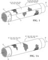
- Figure 1 shows schematic representation of a woven, wrappaple textile sleeve, referred to hereafter as sleeve 10, constructed in accordance with one aspect of the invention
- Figure 1A shows a similar view of a circumferentially continuous sleeve 10' constructed in accordance with another aspect of the invention.
- the sleeve 10 has a wrappable elongate wall 12, while the sleeve 10' has a circumferentially continuous, seamless wall 12', each for routing and protecting an elongate member(s), such as wires or a wire harness 14, for example, from exposure to abrasion and the ingress of contamination, debris and the like.
- the sleeves 10, 10' and the associated yarns, discussed hereafter, used for their construction are similar, and thus, the discussion hereafter is directed to the sleeve 10, for sake of simplicity only, with it to be recognized that the same discussion applies equally to the sleeve 10', unless specifically stated otherwise.
- the elongate wall 12, unlike wall 12' has opposite edges 16, 17 extending generally parallel to a central, longitudinal axis 18, wherein the edges 16, 17 are preferably biased into overlapping relation with one another in "cigarette wrapped" fashion to fully enclose the elongate members 14 within a central cavity 20 of the sleeve 10.
- the wall 12, 12' is woven with separate, discrete warp yarn bundles 22 extending generally parallel to the central longitudinal axis 18, wherein each bundle 22 is made up of a plurality of warp yarns 23 arranged in side-by-side, abutting relation with one another.
- the bundles 22 provide the outer surface of the wall 12, 12' with an increased surface area of warp yarn 23 material, with the increased surface area of yarn material acting to distribute loads applied on the outer surface uniformly and widely over and beyond the impacted area of the wall 12, 12', thereby acting to reduce high point loads, thus, reducing abrasion.
- the wall 12, 12' is further woven with weft yarns, also commonly referred to as fill yarns 24, extending generally circumferentially about the wrapped wall 12 in generally transverse relation to the warp yarns 23.
- the fill yarns 24 can be provided, at least in part, as heat-settable yarns, if desired, such that upon heat-setting the fill yarns 24 while a curled or wrapped configuration, the wall 12 is biased to self-curl the opposite edges 16, 17 into overlapping relation with one another.
- the bias is imparted by heat-setting the fill yarns 24, such as heat-settable monofilament yarns, into their curled configuration about the central longitudinal axis 18, thereby rendering the wall 12 self-curling, also referred to as self-wrapping.
- the wall 12, 12' can be constructed having any suitable size, including length and diameter.
- the edges 16, 17 When the wall 12 is in its self-wrapped tubular configuration, generally free from any externally applied forces, the edges 16, 17 preferably overlap one another in self-biased fashion at least slightly to fully enclose the cavity 20, and thus, provide enhanced protection to the wires 14 contained in the cavity 20.
- the edges 16, 17 are readily extendable away from one another under an externally applied force sufficient to overcome the shape memory bias imparted by the fill yarns 24 to at least partially open and expose the cavity 20. Accordingly, the wires 14 can be readily disposed into the cavity 20 during assembly or removed from the cavity 20 during service.
- the edges 16, 17 Upon releasing the externally applied force, the edges 16, 17 return automatically to their shape memory, overlapping self-wrapped position under the bias imparted by the heat-set fill monofilament yams 24.
- the discrete warp yarn bundles 22, in accordance with one aspect of the disclosure, can be formed of any suitable monofilament yarns 23.
- a wall 112, 112' of a sleeve 110, 110' can include at least one warp monofilament 23' within the discrete bundles 22 of warp monofilaments 23 having a different diameter (larger) from other ones of the warp monofilaments 23 within the discrete bundle 22, thereby providing enhanced abrasion protection to the smaller diameter warp monofilaments 23.
- Figure 2A illustrating only the area identified in FIG. 2 , with the remaining portion of the wall 112, 112' repeating as shown in FIG.
- the bundles 22 were formed with three (3) monofilament warp yarns 23, though two (2) or more warp yarns 23 could be used; however, it has been discovered that having at least three (3) warp yarns 23 provides greatly improved abrasion resistance protection.
- the discrete bundles 22 are shown in Figures 2 and 2A , by way of example and without limitation, as being woven in a warp rib-type weave pattern, with each discrete bundle 22 extending over a common single fill yarn 24 and then under a common single fill yarn 24, in repeating fashion, though other warp rib-type weave .
- the fill yarns 24 can be provided as any suitable monofilament and/or multifilament material, including heat-settable monofilament and/or multifilament polymeric material.
- the fill yarns 24 are provided as both heat-settable monofilaments 24' (though non-heat-settable monofilaments can be used, particularly with the wall 12') and high coverage multifilaments 24, spaced from one another such that the immediately adjacent yarns 24, 24' extend, respectively, over and under the same warp yarn 23 (a fill yarn 24 extends over a first warp yarn 23 while an immediately adjacent fill yarn 24' extends under the first warp yarn 23).
- the fill yarn 24 monofilaments and multifilaments are woven in alternating fashion with one another along the length of the sleeve 10.
- the fill yarns 24, 24' can be provided having a reduced cross-section area (reduced diameter) relative to at least some of the warp yarns 23, which facilitates providing the sleeve 10 with an increased degree of flexibility, while also inhibiting abrasion of the fill yarns 24, 24', given the more numerous and tightly packed warp monofilaments 23 are prone to absorb the abrasion.
- the warp monofilaments 23' can be provided having a larger diameter relative to the fill yarns 24, 24' to enhance abrasion protection to the fill yarns 24, 24'.
- the fill yarns 24, 24' become abraded, it has been discovered that the tightly packed, abutting warp yarns 23, 23' of the bundles 22 are able to maintain the integrity of the structure of the wall 12, 12', thereby maintaining protection of the elongate member(s) 14.
- the fill yarns 24 can be provided having a relative low pick density (picks-per-inch), which ultimately increases the production run rate (speed at which the wall 12, 12' is woven), thereby decreasing cost of manufacture, while also decreasing the overall material content, and thus, further reducing costs associated with production of the sleeve 10.
- the yarns 23, 24, 24' can be provided of any desired thermoplastic material, such as one or more of polyester, PPS, Nomex, by way of example and without limitation, and further can include inorganic material, such as one or more of fiberglass and basalt, by way of example and without limitation.
- At least one warp monofilament 23' within one or more of the discrete bundles 22 of warp monofilaments 23 can be a different type of material from other ones of the warp monofilaments 23 within the discrete bundle 22.
- At least one warp monofilament 23' within one or more of the discrete bundles 22 can have a different diameter and be formed of a different type of material from other ones of the warp monofilaments 23 within the discrete bundle 22. Accordingly, synergies can be optimized by providing the warp monofilaments 23, 23' within a common bundle 22 having different diameters and/or from different materials, to both enhance abrasion resistance, while at the same time improving economies of manufacture and reducing cost.
- At least one warp monofilament 23' within one or more of the discrete bundles 22 of warp monofilaments 23 can have a larger diameter, such as about 0.25mm, for example, and be formed of a different type of material, such as Nylon, for example, from other ones of the warp monofilaments 23 having a diameter of about 0.22mm, for example, and being formed of PET, for example, within the discrete bundle 22.
- the larger diameter monofilaments 23' are provided to enhance abrasion resistance from an optimally abrasion resistant material, e.g.
- Nylon Nylon, thereby providing protection to the smaller, less expensive monofilaments 23, which also provide enhanced abrasion resistance in synergistic fashion with the larger diameter monofilaments 23'. It is to be recognized that the diameters and materials selected for the warp monofilaments 23, 23' can be selected as desired for the intended application.
- a wall 212, 212' of a sleeve 210, 210' can include the fill yarns being provided including multifilaments 24 and monofilaments 24' in bundled, side-by-side relation with one another, such that each passage (woven as a single pick) of the fill yarn includes both the multifilament 24 and the monofilament 24' either pulled in parallel relation with one another, twisted (both are helically spiraled together) with one another, or served (one is helically spiraled about the other) with one another, such that the bundled multifilament and monofilament fill yarns 24, 24' extend over and under the same warp yarns 23, 23' in side-by-side relation with one another, to provide an improved self-wrapping configuration and optimal optical coverage to the sleeve.
- a wall 312, 312' of a sleeve 310, 310' can be constructed in similar fashion as discussed above for the wall 212, 212'; however, the fill yarns can be provided including only multifilaments 24 woven with bundles 22 of warp yarns 23 and optionally warp yarns 23'.
- a wall of a sleeve can be constructed in similar fashion as discussed above for any of the walls 12, 12', 112, 112', 212, 212', 312, 312'; however, at least one of the warp yarns within each of the bundles 22 can be provided as multifilaments 23". Accordingly, the coverage against ingress of contamination and the flexibility of the wall are greatly increased.
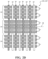
- Figure 2D (illustrating a view similar to FIG.
- a wall 412, 412' of a sleeve 410, 410' can be constructed in similar fashion as discussed above for any of the walls 12, 12', 112, 112', 212, 212', 312, 312'; however all of the warp yarns within each of the bundles 22 are provided as multifilaments 23".
- the sleeve 410, 410' is outside the scope of the invention.
- a wall of a sleeve can be constructed in similar fashion as discussed above for any of the walls 12, 12', 112, 112', 212, 212', 312, 312'; however, at least one of the bundles 22, can be provided as multifilaments 23". Accordingly, alternating bundles 22 include only multifilaments 23" and alternating bundles 22 include only monofilaments 23. Accordingly, the coverage against ingress of contamination and the flexibility of the wall are greatly increased by the multifilaments 23" as is the resistance to abrasion by the monofilaments 23.
- Figure 2E (illustrating a view similar to FIG.
- a wall 512, 512' of a sleeve 510, 510' can be constructed in a similar fashion as discussed above for any of the walls 12, 12', 112, 112', 212, 212', 312, 312'; however, at least one of the bundles 22, shown as alternating bundles 22, is provided as multifilaments 23". Accordingly, alternating bundles 22 include only multifilaments 23" and alternating bundles 22 include only monofilaments 23.
- the sleeve 510, 510' shown in Figure 2E is outside the scope of the invention when the monofilaments 23 in the bundles 22 that include only monofilaments 23 have the same diameter as each other.
- a wall 612, 612' of a sleeve 610, 610' can be constructed in similar fashion as discussed above for any of the walls 12, 12', 112, 112', 212, 212', 312, 312'; however, each of the bundles 22 can be provided including multifilaments 23" and monofilaments 23.
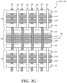
- a wall 712, 712' of a sleeve 710, 710' can be constructed in similar fashion as discussed above for any of the walls 12, 12', 112, 112', 212, 212', 312, 312'; however, each of the bundles 22 can be provided including multifilaments 23" and monofilaments 23, such as discussed for wall 612, 612'; however, the multifilaments 23" and monofilaments 23 are arranged differently. In the embodiment shown, each of the bundles 22 multifilaments 23" in side-by-side, abutting relation with one another.
- a pair of multilaments 23 are arranged in side-by-side, abutting relation with one another, and a single monofilament 23 is arranged along each side of the pair of multifilaments 23" in abutment therewith. Accordingly, the increased surface friction of the multiflaments 23" acts to fix and lock the abutting monofilaments 23 in place. Accordingly, the coverage against ingress of contamination and the flexibility of the wall 712, 712' are greatly increased by the multifilaments 23" as is the resistance to abrasion by the monofilaments 23.
- a wall 812 of a sleeve 810 can be constructed in similar fashion as discussed above for any of the walls 12, 112, 212, 312, with the wall 812 having opposite edges 816, 817 extending generally parallel to a central, longitudinal axis 818, wherein the edges 816, 817 are preferably biased into overlapping relation with one another.
- At least one or both edges 816, 817 can include edge regions 816', 817' spanning a plurality of warp yarns 23 along the entirety of the length of the sleeve 810, such as between about 4-10 warp yarns 23, by way of example and without limitation, wherein the edge regions 816', 817' are woven with a plain weave pattern. Accordingly, the fill yarn 24, 24' within the edge region 816', 817' is woven with the warp yarns 23 in a plain weave pattern.
- An intermediate main body region 30 extending between and from one edge region 816' to the opposite edge region 817' is woven with the warp rib weave pattern of the fill yarn 24, 24' with the warp yarn 23, as discussed above.
- opposite edge regions 816', 817' having a plain weave pattern, it has been found that upon bending the sleeve 810 about sharp corners, the opposite edges 816, 817 remain in their overlapped relation with one another, and avoid being separated or otherwise opened from one another. Accordingly, openings between the opposite edges 816, 817 are inhibited, thereby providing optimal coverage to the elongate member 14 contained within the sleeve 810.
Landscapes
- Engineering & Computer Science (AREA)
- Textile Engineering (AREA)
- Architecture (AREA)
- Civil Engineering (AREA)
- Structural Engineering (AREA)
- Woven Fabrics (AREA)
Description
- This invention relates generally to textile sleeves for protecting elongate members, and more particularly to woven sleeves.
- It is known to contain and protect elongate members, such as wires and wire harnesses, for example, in woven protective sleeves, such as in automobiles, aircraft or aerospace craft, to provide protection to the wires against abrasion, fluid and thermal affects. In order to achieve the multiple types of desired protection, and to ensure optimal protection to the elongate members against the effects of abrasion, the protective sleeve may have multiple layers, with some of the layers being specifically provided for different types of protection. For example, one layer may be provided for optical coverage to inhibit seeing through the sleeve, e.g. a sheet of plastic material, while another layer may be provided for abrasion resistance, and yet another layer may be provided for protection against thermal conditions. Although the aforementioned multilayer sleeves may provide suitable protection against various environmental conditions, unfortunately they are typically bulky, thereby requiring an increased volume of space, and further, they tend to be relatively heavy and exhibit low flexibility. Further yet, providing suitable protection against abrasion can still remain a challenge. Having to include multiple layers can prove problematic in some applications, particularly applications requiring routing cables or hoses through tight, winding areas, as well as applications having weight restrictions, such as aircraft and aerospace applications, for example.
- Prior patent document
US 2015/337465 A1 describes an example of a woven sleeve. The sleeve has a wall constructed from woven monofilament and/or multifilament yarns. The wall has opposite edges extending generally parallel to a central axis of the sleeve, wherein the opposite edges overlap one another. The wall is woven with warp yarns that extend generally parallel to the central axis of the sleeve and fill yarns that extend circumferentially about the sleeve, generally transversely to the central axis. The warp yarns are bundled into individual, discrete groups, with each group including a plurality of yarns in side-by-side relation with one another, wherein each of the yarns within the same discrete group is interlaced over the same side of a common fill yarn. - The invention is defined by the appended claims. One aspect of the invention provides a woven textile sleeve for routing and protecting elongate members including an elongate wall configured to bound a cavity extending a longitudinal central axis of the sleeve. The wall is woven with warp yarns extending parallel to the central longitudinal axis and fill yarns extending transversely to the warp yarns. The warp yarns are woven as discrete bundles of yarns. Each of the discrete bundle of yarns includes a plurality of yarns arranged in side-by-side abutting relation with one another. The yarn filaments in each discrete bundle extend over and under the same fill yarns with one another. At least some of said discrete bundles include monofilaments. At least one of said monofilaments within said discrete bundles has a larger diameter from other yarns within said discrete bundle.
- In accordance with another aspect, the invention provides a method of constructing a textile sleeve, comprising: weaving an elongate wall configured to bound a central cavity extending parallel to a central longitudinal axis of the sleeve with the wall having warp yarns extending parallel to the central longitudinal axis and fill yarns extending transverse to the warp yarns. Further, weaving the warp yarns in discrete bundles of yarns, with each of the bundles having a plurality of yarns arranged in side-by-side abutting relation with one another, with the yarns in each discrete bundle extending over and under the same fill yarns with one another. Further, weaving at least some of the discrete bundles including monofilaments, wherein at least one of said monofilaments within said discrete bundles has a larger diameter from other yarns within said discrete bundle. Further yet, the method can further include providing the fill yarns asmonofilaments and multifilaments.
- In accordance with an embodiment of the invention, there is provided a woven sleeve for routing and protecting elongate members from exposure to abrasion and other environmental conditions, such as contamination. The sleeve has a flexible, abrasion resistant wall constructed from woven monofilament and multifilament yarns. The wall is configured to bound a cavity that extends along a central axis of the sleeve between opposite open ends. The wall is woven with warp yarns that extend generally parallel to the central axis of the sleeve and fill (also referred to as weft) yarns that extend circumferentially about the central axis of the sleeve, generally transversely to the central axis. The warp yarns are bundled into individual, discrete groups, with each group including a plurality of monofilaments in immediate, side-by-side, abutting relation with one another, wherein each of the monofilaments within the same discrete group is interlaced to extend over and under the same side of a same (common) fill yarn. The groups of bundled warp yarns provide enhanced abrasion resistance to abrasive forces along the length of the sleeve, while also providing the sleeve with a relatively reduced weight as compared to a similar plain weave sleeve (a plain weave does not include discrete groups of side-by-side yarns) of the same size, while the synergies provided by the warp and fill yarns further provide the sleeve with enhanced optical coverage, an ability to flex smoothly without kinking about meandering paths and corners, while also being economical in manufacture and in use. At least some of said discrete groups include monofilaments. At least one of said monofilaments within said discrete groups has a larger diameter from other yarns within said discrete bundle.
- In accordance with another aspect of the invention, the wall of the sleeve can be constructed as a circumferentially continuous, seamless tubular wall.
- In accordance with another aspect of the invention, the wall of the sleeve can be formed as a wrappable wall having opposite edges extending generally parallel with the central axis, wherein the opposite edges are configured to overlap one another to bound the cavity configured for receipt of the elongate member to be protected.
- In accordance with another aspect of the invention, the discrete bundles of warp monofilaments can extend over a single fill yarn and under a single fill yarn in repeating fashion.
- In accordance with another aspect of the invention, the discrete bundles of warp monofilaments can extend over a plurality of the fill yarns and under a plurality of the fill yarns in repeating fashion.
- In accordance with another aspect of the invention, each of the discrete bundles of warp monofilaments can be provided having three (3) or more monofilaments to provide enhanced abrasion resistance.
- In accordance with another aspect of the invention, the fill yarns can be provided as multifilaments and monofilaments, with the multifilaments providing enhanced optical coverage and the monofilaments being heat-set to bias the opposite edges of the wall into overlapping relation with one another.
- In accordance with another aspect of the invention, the fill yarns can be provided including multifilaments and monofilaments in alternating relation with one another along the length of the sleeve, such that the immediately adjacent fill yarns extend over and under, respectively, the same warp yarn, to provide an optimal self-wrapping configuration and optimal optical coverage to the sleeve.
- In accordance with another aspect of the invention, the fill yarns can be provided including multifilaments and monofilaments in bundled, side-by-side relation with one another, such that each passage (pick) of the fill yarn includes a multifilament and a monofilament either pulled in parallel relation with one another, twisted with one another, or served with one another, such that the bundled multifilament and monofilament fill yarns extend over and under the same warp yarn in side-by-side relation with one another, to provide an optimal self-wrapping configuration and optimal optical coverage to the sleeve.
- In accordance with another aspect of the invention, the warp monofilaments can be provided having a larger diameter relative to the fill yarns to enhance abrasion protection to the fill yarns.
- In accordance with another aspect of the invention, at least one warp monofilament within one or more of the discrete bundles of warp monofilaments can have a different diameter from other ones of the warp monofilaments within the discrete bundle, with the warp monofilaments having the greater diameter providing protection to the warp monofilaments having the lesser diameter.
- In accordance with another aspect of the invention, at least one warp monofilament within one or more of the discrete bundles of warp monofilaments can be a different type of material from other ones of the warp monofilaments within the discrete bundle.
- In accordance with another aspect of the invention, at least one warp monofilament within one or more of the discrete bundles of warp monofilaments can have a different diameter and be formed of a different type of material from other ones of the warp monofilaments within the discrete bundle.
- In accordance with another aspect of the invention, at least one warp monofilament within one or more of the discrete bundles of warp monofilaments can have a larger diameter, such as about 0.25mm, for example, and be formed of a different type of material, such as Nylon, for example, from other ones of the warp monofilaments having a diameter of about 0.22mm, for example, and being formed of PET, for example, within the discrete bundle. The larger diameter monofilaments are provided to enhance abrasion resistance from an optimally abrasion resistant material, thereby providing protection to the smaller, less expensive monofilaments, which also provide enhanced abrasion resistance in synergistic fashion with the larger diameter monofilaments.
- In accordance with another aspect of the invention, a method of constructing a textile sleeve is provided. The method includes weaving an elongate wall configured to bound a cavity that extends along a central longitudinal axis of the sleeve with the wall being having warp yarns extending parallel to the central longitudinal axis and fill yarns extending transverse to the warp yarns. Further, the method includes weaving the warp yarns in discrete bundles of yarns, with each of the bundles having a plurality of monofilament yarns arranged in side-by-side abutting relation with one another, wherein the warp yarns in each discrete bundle extends over and under the same fill yarns with one another. The method further includes weaving at least one warp monofilament within some of the discrete bundles of warp monofilaments having a larger diameter from other ones of the yarns within the discrete bundle.
- In accordance with another aspect of the invention, the method can further include weaving the wall having opposite edges extending generally parallel to the central longitudinal axis, and wrapping the opposite edges in overlapping relation with one another to circumferentially bound the cavity.
- In accordance with another aspect of the invention, the method can further include weaving the wall as a circumferentially continuous, seamless tubular wall.
- In accordance with another aspect of the invention, the method can further include weaving the bundles over and under a single fill yarn in repeating fashion.
- In accordance with another aspect of the invention, the method can further include heat-setting at least some of the fill yarns to bias the opposite edges into overlapping relation with one another.
- In accordance with another aspect of the invention, the method can further include providing the fill yarns as monofilaments and multifilament yarns.
- In accordance with another aspect of the invention, the method can further include weaving the fill yarns as monofilaments and multifilament yarns in alternating relation with another along the length of the sleeve.
- In accordance with another aspect of the invention, the method can further include weaving the warp yarns and the fill yarns in a warp rib weave pattern.
- In accordance with another aspect of the invention, the method can further include weaving at least one warp monofilament within one or more of the discrete bundles of warp monofilaments having a different diameter from other ones of the warp monofilaments within the discrete bundle to further enhance the abrasion resistance of the wall and reduce the cost associated with manufacture of the wall.
- In accordance with another aspect of the invention, the method can further include weaving at least one warp monofilament within one or more of the discrete bundles of warp monofilaments of a different type of material from other ones of the warp monofilaments within the discrete bundle to further enhance the abrasion resistance of the wall and reduce the cost associated with manufacture of the wall.
- In accordance with another aspect of the invention, the method can further include weaving at least one warp monofilament within one or more of the discrete bundles of warp monofilaments having a different diameter and being formed of a different type of material from other ones of the warp monofilaments within the discrete bundle to further enhance the abrasion resistance of the wall and reduce the cost associated with manufacture of the wall.
- In accordance with another aspect of the invention, the method can further include weaving at least one warp monofilament within one or more of the discrete bundles of warp monofilaments having a larger diameter, such as about 0.25mm, for example, and being formed of a different type of material, such as Nylon, for example, from other ones of the warp monofilaments having a diameter of about 0.22mm, for example, and being formed of PET, for example, within the discrete bundle, such that the larger diameter monofilaments provide enhanced abrasion resistance with an optimally abrasion resistant material, thereby providing abrasion resistance protection to the smaller, less expensive monofilaments, which also provide enhanced abrasion resistance in synergistic fashion with the larger diameter monofilaments.
- These and other aspects, features and advantages will become readily apparent to those skilled in the art in view of the following detailed description of presently preferred embodiments and best mode, appended claims, and accompanying drawings, in which:
-
Figure 1 is schematic perspective view of a woven, wrappable sleeve constructed in accordance with one aspect of the invention, with the sleeve shown carrying and protecting elongate members therein; -
Figure 1A is a view similar toFigure 1 of a woven, circumferentially continuous sleeve constructed in accordance with another aspect of the invention, with the sleeve shown carrying and protecting elongate members therein; -
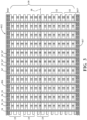
Figure 2 is an enlarged schematic plan view of a portion of a wall of the sleeves ofFigures 1 and 1A constructed in accordance with one embodiment of the invention; -
Figure 2A is a view similar toFigure 2 illustrating a portion of a wall of the sleeves ofFigures 1 and 1A constructed in accordance with another embodiment of the invention; -
Figure 2B is a view similar toFigure 2 illustrating a portion of a wall of the sleeves ofFigures 1 and 1A constructed in accordance with yet another embodiment of the invention; -
Figure 2C is a view similar toFigure 2 illustrating a portion of a wall of the sleeves ofFigures 1 and 1A constructed in accordance with yet another embodiment of the invention; -
Figure 2D is a view similar toFigure 2 illustrating a portion of a wall of the sleeves ofFigures 1 and 1A constructed in accordance with an example outside the scope of the invention; -
Figure 2E is a view similar toFigure 2 illustrating a portion of a wall of the sleeves ofFigures 1 and 1A constructed in accordance with an example outside the scope of the invention; -
Figure 2F is a view similar toFigure 2 illustrating a portion of a wall of the sleeves ofFigures 1 and 1A constructed in accordance with another embodiment of the invention; -
Figure 2G is a view similar toFigure 2 illustrating a portion of a wall of the sleeves ofFigures 1 and 1A constructed in accordance with another embodiment of the invention; and -
Figure 3 is a plan view of a wall of the sleeves ofFigure 1 constructed in accordance with another non-limiting embodiment of the disclosure shown prior to being wrapped into a tubular configuration. - Referring in more detail to the drawings,
Figure 1 shows schematic representation of a woven, wrappaple textile sleeve, referred to hereafter as sleeve 10, constructed in accordance with one aspect of the invention, whileFigure 1A shows a similar view of a circumferentially continuous sleeve 10' constructed in accordance with another aspect of the invention. The sleeve 10 has a wrappableelongate wall 12, while the sleeve 10' has a circumferentially continuous, seamless wall 12', each for routing and protecting an elongate member(s), such as wires or awire harness 14, for example, from exposure to abrasion and the ingress of contamination, debris and the like. Other than thewall 12 being wrappable and the wall 12' being circumferentially continuous and seamless, the sleeves 10, 10' and the associated yarns, discussed hereafter, used for their construction are similar, and thus, the discussion hereafter is directed to the sleeve 10, for sake of simplicity only, with it to be recognized that the same discussion applies equally to the sleeve 10', unless specifically stated otherwise. Theelongate wall 12, unlike wall 12', has opposite edges 16, 17 extending generally parallel to a central,longitudinal axis 18, wherein theedges elongate members 14 within acentral cavity 20 of the sleeve 10. Thecavity 20, unlike cavity 20' (Figure 1A ), is readily accessible along the full length of thewall 12, via separation of theopposite edges axis 18, into thecavity 20, and conversely, removed from thecavity 20, such as during service. To provide the desired protection to theelongate members 14 against abrasion, and to optimize the structural integrity of thewall 12, 12' against wear from abrasion, thewall 12, 12' is woven with separate, discrete warp yarn bundles 22 extending generally parallel to the centrallongitudinal axis 18, wherein eachbundle 22 is made up of a plurality ofwarp yarns 23 arranged in side-by-side, abutting relation with one another. Thebundles 22, havingmultiple warp yarns 23 in abutting, side-by-side relation, minimize yarn movement within thewall 12, 12', such that theindividual warp yarns 23 within eachbundle 22 do not move significant relative to one another, thereby reducing internal friction within thewall 12, 12', which in turn reduces abrasion betweenwarp yarns 23, even while thewall 12, 12' is moving in abutment against some external vehicle member, such as an engine component or frame member, by way of example and without limitation. Additionally, thebundles 22 provide the outer surface of thewall 12, 12' with an increased surface area ofwarp yarn 23 material, with the increased surface area of yarn material acting to distribute loads applied on the outer surface uniformly and widely over and beyond the impacted area of thewall 12, 12', thereby acting to reduce high point loads, thus, reducing abrasion. Thewall 12, 12' is further woven with weft yarns, also commonly referred to as fillyarns 24, extending generally circumferentially about the wrappedwall 12 in generally transverse relation to thewarp yarns 23. Thefill yarns 24 can be provided, at least in part, as heat-settable yarns, if desired, such that upon heat-setting thefill yarns 24 while a curled or wrapped configuration, thewall 12 is biased to self-curl theopposite edges fill yarns 24, such as heat-settable monofilament yarns, into their curled configuration about the centrallongitudinal axis 18, thereby rendering thewall 12 self-curling, also referred to as self-wrapping. It is to be recognized that by reducing the relative movement betweenwarp yarns 23, there is also a corresponding reduction in reduced relative movement and friction between thewarp yarns 23 and thefill yarns 24, thereby further reducing internal friction and abrasion within thewall 12, 12'. - Depending on the application needs, the
wall 12, 12' can be constructed having any suitable size, including length and diameter. When thewall 12 is in its self-wrapped tubular configuration, generally free from any externally applied forces, theedges cavity 20, and thus, provide enhanced protection to thewires 14 contained in thecavity 20. Theedges fill yarns 24 to at least partially open and expose thecavity 20. Accordingly, thewires 14 can be readily disposed into thecavity 20 during assembly or removed from thecavity 20 during service. Upon releasing the externally applied force, theedges fill monofilament yams 24. - The discrete warp yarn bundles 22, in accordance with one aspect of the disclosure, can be formed of any
suitable monofilament yarns 23. Themonofilament warp yarns 23, in addition to providing enhanced abrasion resistance as a result of being bundled in side-by-side, abutting or substantially abutting relation with one another, provide enhanced, optimal surface area coverage to thewall 12, thereby inhibiting the ingress of contamination, debris, or the like into thecavity 20, thereby providing enhanced protection to theelongate members 14 contained within thecavity 20. In one exemplary sleeve embodiment (Figure 2 ), thebundles 22 were formed with four (4)monofilament warp yarns 23, and in another exemplary embodiment (Figure 2A ), awall 112, 112' of a sleeve 110, 110' can include at least one warp monofilament 23' within thediscrete bundles 22 ofwarp monofilaments 23 having a different diameter (larger) from other ones of thewarp monofilaments 23 within thediscrete bundle 22, thereby providing enhanced abrasion protection to the smallerdiameter warp monofilaments 23. In the non-limiting embodiment ofFigure 2A (illustrating only the area identified inFIG. 2 , with the remaining portion of thewall 112, 112' repeating as shown inFIG. 2 ), thebundles 22 were formed with three (3)monofilament warp yarns 23, though two (2) ormore warp yarns 23 could be used; however, it has been discovered that having at least three (3)warp yarns 23 provides greatly improved abrasion resistance protection. Thediscrete bundles 22 are shown inFigures 2 and2A , by way of example and without limitation, as being woven in a warp rib-type weave pattern, with eachdiscrete bundle 22 extending over a commonsingle fill yarn 24 and then under a commonsingle fill yarn 24, in repeating fashion, though other warp rib-type weave . - The
fill yarns 24 can be provided as any suitable monofilament and/or multifilament material, including heat-settable monofilament and/or multifilament polymeric material. In the exemplary sleeve embodiments shown inFigures 2 and2A , thefill yarns 24 are provided as both heat-settable monofilaments 24' (though non-heat-settable monofilaments can be used, particularly with the wall 12') andhigh coverage multifilaments 24, spaced from one another such that the immediatelyadjacent yarns 24, 24' extend, respectively, over and under the same warp yarn 23 (afill yarn 24 extends over afirst warp yarn 23 while an immediately adjacent fill yarn 24' extends under the first warp yarn 23). To provide thewall 12 with increased self-wrapping capacity and increased optical coverage, to inhibit seeing through thewall 12 into thecavity 20, thereby enhancing protection against the ingress of contamination, thefill yarn 24 monofilaments and multifilaments are woven in alternating fashion with one another along the length of the sleeve 10. As shown inFigure 2A , thefill yarns 24, 24' can be provided having a reduced cross-section area (reduced diameter) relative to at least some of thewarp yarns 23, which facilitates providing the sleeve 10 with an increased degree of flexibility, while also inhibiting abrasion of thefill yarns 24, 24', given the more numerous and tightly packedwarp monofilaments 23 are prone to absorb the abrasion. Accordingly, at least some or all the warp monofilaments 23', as shown, can be provided having a larger diameter relative to thefill yarns 24, 24' to enhance abrasion protection to thefill yarns 24, 24'. However, should the fillyarns 24, 24' become abraded, it has been discovered that the tightly packed, abuttingwarp yarns 23, 23' of thebundles 22 are able to maintain the integrity of the structure of thewall 12, 12', thereby maintaining protection of the elongate member(s) 14. Further yet, thefill yarns 24 can be provided having a relative low pick density (picks-per-inch), which ultimately increases the production run rate (speed at which thewall 12, 12' is woven), thereby decreasing cost of manufacture, while also decreasing the overall material content, and thus, further reducing costs associated with production of the sleeve 10. - The
yarns - In accordance with another aspect of the invention at least one warp monofilament 23' within one or more of the
discrete bundles 22 ofwarp monofilaments 23 can be a different type of material from other ones of thewarp monofilaments 23 within thediscrete bundle 22. - In accordance with another aspect of the invention, as shown in
Figure 2A , at least one warp monofilament 23' within one or more of thediscrete bundles 22 can have a different diameter and be formed of a different type of material from other ones of thewarp monofilaments 23 within thediscrete bundle 22. Accordingly, synergies can be optimized by providing thewarp monofilaments 23, 23' within acommon bundle 22 having different diameters and/or from different materials, to both enhance abrasion resistance, while at the same time improving economies of manufacture and reducing cost. For example, in one exemplary embodiment, at least one warp monofilament 23' within one or more of thediscrete bundles 22 ofwarp monofilaments 23 can have a larger diameter, such as about 0.25mm, for example, and be formed of a different type of material, such as Nylon, for example, from other ones of thewarp monofilaments 23 having a diameter of about 0.22mm, for example, and being formed of PET, for example, within thediscrete bundle 22. The larger diameter monofilaments 23' are provided to enhance abrasion resistance from an optimally abrasion resistant material, e.g. Nylon, thereby providing protection to the smaller, lessexpensive monofilaments 23, which also provide enhanced abrasion resistance in synergistic fashion with the larger diameter monofilaments 23'. It is to be recognized that the diameters and materials selected for thewarp monofilaments 23, 23' can be selected as desired for the intended application. - In accordance with another aspect of the invention, as shown in
Figure 2B (illustrating only the area identified inFIG. 2 , with the remaining portion of thewall 212, 212' repeating as shown inFIG. 2 ), awall 212, 212' of a sleeve 210, 210' can include the fill yarns being provided includingmultifilaments 24 and monofilaments 24' in bundled, side-by-side relation with one another, such that each passage (woven as a single pick) of the fill yarn includes both the multifilament 24 and the monofilament 24' either pulled in parallel relation with one another, twisted (both are helically spiraled together) with one another, or served (one is helically spiraled about the other) with one another, such that the bundled multifilament and monofilament fillyarns 24, 24' extend over and under thesame warp yarns 23, 23' in side-by-side relation with one another, to provide an improved self-wrapping configuration and optimal optical coverage to the sleeve. - In accordance with another aspect of the invention, as shown in
Figure 2C (illustrating only the area identified inFIG. 2 , with the remaining portion of thewall 312, 312' repeating as shown inFIG. 2 ), awall 312, 312' of a sleeve 310, 310' can be constructed in similar fashion as discussed above for thewall 212, 212'; however, the fill yarns can be provided including only multifilaments 24 woven withbundles 22 ofwarp yarns 23 and optionally warp yarns 23'. - In accordance with another aspect of the invention, a wall of a sleeve can be constructed in similar fashion as discussed above for any of the
walls bundles 22 can be provided asmultifilaments 23". Accordingly, the coverage against ingress of contamination and the flexibility of the wall are greatly increased. InFigure 2D (illustrating a view similar toFIG. 2 ), awall 412, 412' of a sleeve 410, 410' can be constructed in similar fashion as discussed above for any of thewalls bundles 22 are provided asmultifilaments 23". The sleeve 410, 410' is outside the scope of the invention. - In accordance with another aspect of the invention, a wall of a sleeve can be constructed in similar fashion as discussed above for any of the
walls bundles 22, can be provided asmultifilaments 23". Accordingly, alternatingbundles 22 include only multifilaments 23" and alternatingbundles 22 include only monofilaments 23. Accordingly, the coverage against ingress of contamination and the flexibility of the wall are greatly increased by themultifilaments 23" as is the resistance to abrasion by themonofilaments 23. InFigure 2E (illustrating a view similar toFIG. 2 ), awall 512, 512' of a sleeve 510, 510' can be constructed in a similar fashion as discussed above for any of thewalls bundles 22, shown as alternatingbundles 22, is provided asmultifilaments 23". Accordingly, alternatingbundles 22 include only multifilaments 23" and alternatingbundles 22 include only monofilaments 23. The sleeve 510, 510' shown inFigure 2E is outside the scope of the invention when themonofilaments 23 in thebundles 22 that include onlymonofilaments 23 have the same diameter as each other. - In accordance with another aspect of the invention, as shown in
Figure 2F (illustrating a view similar toFIG. 2 ), awall 612, 612' of a sleeve 610, 610' can be constructed in similar fashion as discussed above for any of thewalls bundles 22 can be provided includingmultifilaments 23" andmonofilaments 23. In the embodiment shown, thebundles 22 including themonofilaments 23 andmultifilaments 23" alternating with one another, such that an increased surface friction of themultiflaments 23" act to fix and lock the abuttingmonofilaments 23 in place. Accordingly, the coverage against ingress of contamination and the flexibility of thewall 612, 612' are greatly increased by themultifilaments 23" as is the resistance to abrasion by themonofilaments 23. - In accordance with another aspect of the invention, as shown in
Figure 2G (illustrating a view similar toFIG. 2 ), awall 712, 712' of a sleeve 710, 710' can be constructed in similar fashion as discussed above for any of thewalls bundles 22 can be provided includingmultifilaments 23" andmonofilaments 23, such as discussed forwall 612, 612'; however, themultifilaments 23" andmonofilaments 23 are arranged differently. In the embodiment shown, each of thebundles 22multifilaments 23" in side-by-side, abutting relation with one another. In the exemplary embodiment, a pair ofmultilaments 23 are arranged in side-by-side, abutting relation with one another, and asingle monofilament 23 is arranged along each side of the pair ofmultifilaments 23" in abutment therewith. Accordingly, the increased surface friction of themultiflaments 23" acts to fix and lock the abuttingmonofilaments 23 in place. Accordingly, the coverage against ingress of contamination and the flexibility of thewall 712, 712' are greatly increased by themultifilaments 23" as is the resistance to abrasion by themonofilaments 23. - In accordance with another aspect of the invention, as shown in
Figure 3 , awall 812 of a sleeve 810 can be constructed in similar fashion as discussed above for any of thewalls wall 812 havingopposite edges edges edges warp yarns 23 along the entirety of the length of the sleeve 810, such as between about 4-10warp yarns 23, by way of example and without limitation, wherein the edge regions 816', 817' are woven with a plain weave pattern. Accordingly, thefill yarn 24, 24' within the edge region 816', 817' is woven with thewarp yarns 23 in a plain weave pattern. An intermediatemain body region 30 extending between and from one edge region 816' to the opposite edge region 817' is woven with the warp rib weave pattern of thefill yarn 24, 24' with thewarp yarn 23, as discussed above. With the opposite edge regions 816', 817' having a plain weave pattern, it has been found that upon bending the sleeve 810 about sharp corners, theopposite edges opposite edges elongate member 14 contained within the sleeve 810. - Obviously, many modifications and variations of the present invention are possible in light of the above teachings. It is, therefore, to be understood that within the scope of the appended claims, the invention may be practiced otherwise than as specifically described.
Claims (15)
- A woven textile sleeve (110; 110'; 210; 210'; 310; 310'; 810) for routing and protecting elongate members (14), comprising:an elongate wall (112; 112'; 212; 212'; 312; 312'; 812) configured to bound a cavity (20) extending a longitudinal central axis (18; 818) of the sleeve, said wall being woven with warp yarns (23, 23') extending parallel to said central longitudinal axis and fill yarns (24, 24') extending transversely to said warp yarns, said warp yarns being woven as discrete bundles (22) of yarns, wherein each said discrete bundle of yarns includes a plurality of yarns arranged in side-by-side abutting relation with one another, with said yarns in each discrete bundle extending over and under the same said fill yarns with one another;wherein at least some of said discrete bundles include monofilaments;characterized in that at least one of said monofilaments within said discrete bundles has a larger diameter from other yarns (23) within said discrete bundle.
- The textile sleeve (110; 110'; 210; 210'; 310; 310'; 810) of claim 1, wherein each said bundle (22) of yarns extends over a single fill yarn (24, 24') and under a single fill yarn in repetition.
- The textile sleeve (110; 110'; 210; 210') of claim 1, wherein said fill yarns (24, 24') include monofilaments (24') and multifilaments (24) that alternate with one another along the longitudinal central axis (18).
- The textile sleeve (110; 210; 310; 810) of claim 1, wherein said wall has opposite edges (16, 17; 816, 817) biased into overlapping relation with one another by at least some of said fill yarns (24, 24') being heat-set.
- The textile sleeve of claim 1, wherein at least some of said bundles include multifilaments.
- The textile sleeve of claim 5, wherein at least some of said bundles include only monofilaments and wherein at least some of said bundles include only multifilaments.
- The textile sleeve of claim 5, wherein at least some of said bundles include monofilaments and multifilaments, and optionally wherein each of said bundles include monofilaments and multifilaments.
- The textile sleeve (110; 110'; 210; 210'; 310; 310'; 810) of claim 1, wherein each of said bundles (22) include only monofilaments.
- The textile sleeve (110; 110'; 210; 210'; 310; 310'; 810) of claim 1, wherein said monofilaments have a larger diameter relative to the fill yarns (24, 24').
- The textile sleeve (110; 110'; 210; 210'; 310; 310'; 810) of claim 1, wherein at least one yarn (23, 23') within at least one of said discrete bundles (22) of warp yarns (23, 23') is a different type of material from other ones of said yarns within said at least one of said discrete bundles or wherein at least one yarn within at least one of said discrete bundles (22) of warp yarns (23, 23') has a different diameter and is formed of a different type of material from other ones of said yarn filaments within said at least one of said discrete bundles.
- The textile sleeve of claim 5, wherein at least some of said bundles include only multifilaments.
- A method of constructing a textile sleeve, comprising:weaving an elongate wall configured to bound a central cavity extending parallel to a central longitudinal axis of the sleeve with the wall having warp yarns extending parallel to the central longitudinal axis and fill yarns extending transverse to the warp yarns;weaving the warp yarns in discrete bundles of yarns, each of the bundles having a plurality of yarns arranged in side-by-side abutting relation with one another, with the yarns in each discrete bundle extending over and under the same fill yarns with one another; and weaving at least some of the discrete bundles including monofilaments,characterised in that at least one of said monofilaments within said discrete bundles has a larger diameter from other yarns (23) within said discrete bundle.
- The method of claim 12, further including providing the fill yarns as monofilaments and multifilaments.
- The method of claim 12 or 13, further including weaving each the bundles including monofilaments and providing at least one monofilament within each of the discrete bundles having a larger diameter from other ones of the yarns within the discrete bundles.
- The method of claim 13, further including weaving each said bundles including multifilaments, and optionally further including weaving each of the monofilaments in the bundles being in side-by-side relation with one of the multifilaments in in the bundles.
Applications Claiming Priority (2)
| Application Number | Priority Date | Filing Date | Title |
|---|---|---|---|
| US201962824217P | 2019-03-26 | 2019-03-26 | |
| PCT/US2020/024908 WO2020198445A1 (en) | 2019-03-26 | 2020-03-26 | Flexible, abrasion resistant, woven sleeve and method of construction thereof |
Publications (2)
| Publication Number | Publication Date |
|---|---|
| EP3947796A1 EP3947796A1 (en) | 2022-02-09 |
| EP3947796B1 true EP3947796B1 (en) | 2024-06-19 |
Family
ID=70293138
Family Applications (1)
| Application Number | Title | Priority Date | Filing Date |
|---|---|---|---|
| EP20719888.8A Active EP3947796B1 (en) | 2019-03-26 | 2020-03-26 | Flexible, abrasion resistant, woven sleeve and method of construction thereof |
Country Status (6)
| Country | Link |
|---|---|
| US (1) | US20220186408A1 (en) |
| EP (1) | EP3947796B1 (en) |
| JP (1) | JP7818403B2 (en) |
| KR (1) | KR102942964B1 (en) |
| CN (1) | CN113710839B (en) |
| WO (1) | WO2020198445A1 (en) |
Families Citing this family (1)
| Publication number | Priority date | Publication date | Assignee | Title |
|---|---|---|---|---|
| CN114375353B (en) * | 2019-09-10 | 2023-08-11 | 费德罗-莫格尔动力系公司 | Corrugated woven sleeve and method of making same |
Family Cites Families (42)
| Publication number | Priority date | Publication date | Assignee | Title |
|---|---|---|---|---|
| US4174739A (en) * | 1978-02-21 | 1979-11-20 | Fenner America Ltd. | Tubular fabric |
| FR2463831B1 (en) * | 1979-08-20 | 1985-10-18 | Alsacienne Constr Meca | VELVET FABRIC AS WELL AS PROCESS AND MATERIAL FOR ITS PREPARATION |
| US4836080A (en) * | 1987-07-29 | 1989-06-06 | The Bentley-Harris Manufacturing Company | Vibration abrasive resistant fabric covering |
| US5413149A (en) * | 1991-11-05 | 1995-05-09 | The Bentley-Harris Manufacturing Company | Shaped fabric products and methods of making same |
| US5467802A (en) * | 1994-01-21 | 1995-11-21 | The Bentley-Harris Manufacturing Company | Woven sleeve with integral lacing cord |
| US5843542A (en) * | 1997-11-10 | 1998-12-01 | Bentley-Harris Inc. | Woven fabric having improved flexibility and conformability |
| WO1999055945A1 (en) * | 1998-04-27 | 1999-11-04 | Federal-Mogul Systems Protection Group Inc. | Braided tubular article with restraining element |
| US6718100B2 (en) * | 2002-03-28 | 2004-04-06 | Milliken & Company | Fire resistant conduit insert for optical fiber cable |
| TW200624617A (en) * | 2004-07-20 | 2006-07-16 | Federal Mogul World Wide Inc | Self-curling sleeve |
| US7600539B2 (en) * | 2006-03-03 | 2009-10-13 | Federal-Mogul World Wide, Inc | Low profile textile wire bundler sleeve |
| FR2902802B1 (en) * | 2006-06-21 | 2008-12-12 | Snecma Propulsion Solide Sa | FIBROUS REINFORCING STRUCTURE FOR A PIECE OF COMPOSITE MATERIAL AND PART COMPRISING THE SAME |
| US20080135119A1 (en) * | 2006-12-07 | 2008-06-12 | Takashi Tonooka | Protective sleeve assembly having a support member and method of construction |
| US7874184B2 (en) * | 2007-08-23 | 2011-01-25 | Federal-Mogul Powertrain, Inc. | Thermal protection sleeve with knit thermal protection features and method of construction thereof |
| US8925592B2 (en) | 2009-06-11 | 2015-01-06 | Federal-Mogul Powertrain, Inc. | Flexible, abrasion resistant textile sleeve and method of construction thereof |
| JP6279832B2 (en) * | 2009-06-11 | 2018-02-14 | フェデラル−モーグル・パワートレイン・リミテッド・ライアビリティ・カンパニーFederal−Mogul Powertrain Llc | Flexible, abrasion-resistant textile sleeve and its construction method |
| CN103038403B (en) * | 2010-07-29 | 2015-06-24 | 旭化成纤维株式会社 | Abrasion-resistant polyester fibers and woven/knitted fabrics |
| US20120132309A1 (en) * | 2010-11-30 | 2012-05-31 | Morris David D | Woven textile fabric and innerduct having multiple-inserted filling yarns |
| US8444827B2 (en) * | 2011-02-02 | 2013-05-21 | Voith Patent Gmbh | Structured fabric |
| CN103596808B (en) * | 2011-04-18 | 2016-05-11 | 费德罗-莫格尔动力系公司 | A kind of multi-layered textile sleeve and building method thereof |
| RU2618419C2 (en) * | 2012-03-01 | 2017-05-03 | Федерал-Могал Пауэртрейн, Инк. | Protective textile shell for elongated objects protection and method for its manufacture |
| US9478954B2 (en) * | 2012-04-11 | 2016-10-25 | Federal-Mogul Powertrain, Inc. | Self-curling non-woven sleeve and method of construction thereof |
| US9913415B2 (en) * | 2013-03-13 | 2018-03-06 | Federal-Mogul Powertrain Llc | EMI shielding textile fabric, wrappable sleeve constructed therefrom and method of construction thereof |
| US9277684B2 (en) * | 2013-03-13 | 2016-03-01 | Federal-Mogul Powertrain, Inc. | Self-wrapping EMI shielding textile sleeve and method of construction thereof |
| US10132012B2 (en) * | 2013-03-14 | 2018-11-20 | Federal-Mogul Powertrain Llc | End-fray resistant heat-shrinkable woven sleeve, assembly therewith and methods of construction thereof |
| WO2014149575A1 (en) * | 2013-03-15 | 2014-09-25 | Federal-Mogul Powertrain, Inc. | Flexible, abrasion resistant textile sleeve and method of construction thereof |
| KR20160124128A (en) * | 2014-02-20 | 2016-10-26 | 페더럴-모걸 파워트레인 엘엘씨 | Nonkinking wrappable knit sleeve and method of construction thereof |
| US9416469B2 (en) * | 2014-05-21 | 2016-08-16 | Federal-Mogul Powertrain, Inc. | Flexible, abrasion resistant woven textile sleeve and method of construction thereof |
| EP3146099B1 (en) * | 2014-05-21 | 2021-08-25 | Federal-Mogul Powertrain LLC | Flexible, abrasion resistant woven textile sleeve and method of contruction thereof |
| KR20170031731A (en) * | 2014-07-16 | 2017-03-21 | 페더럴-모걸 파워트레인 엘엘씨 | Wrappable abrasion resistant, reflective thermal protective textile sleeve and method of construction thereof |
| US10192655B2 (en) * | 2014-09-30 | 2019-01-29 | Highland Industries, Inc. | Anisotropic wire harness |
| US10542645B2 (en) * | 2015-04-17 | 2020-01-21 | Federal-Mogul Powertrain Llc | EMI protective sleeve and method of construction thereof |
| US10675832B2 (en) * | 2015-06-08 | 2020-06-09 | Federal-Mogul Powertrain Llc | Transparent, end-fray and EMI resistant textile sleeve and method of construction thereof |
| US10357933B2 (en) * | 2015-08-04 | 2019-07-23 | Federal-Mogul Powertrain Llc | Woven tubular thermal sleeve and method of construction thereof |
| US11268217B2 (en) * | 2015-12-18 | 2022-03-08 | Federal-Mogul Powertrain Llc | Wrappable end fray resistant woven protective textile sleeve and method of construction thereof |
| US10590574B2 (en) * | 2016-01-22 | 2020-03-17 | Federal-Mogul Powertrain Llc | Abrasion resistant braided textile sleeve and method of construction thereof |
| US11168415B2 (en) * | 2016-07-01 | 2021-11-09 | Federal-Mogul Powertrain Llc | Circumferentially continuous and constrictable textile sleeve and method of construction thereof |
| US11180872B2 (en) * | 2016-08-24 | 2021-11-23 | Federal-Mogul Powertrain Llc | Impact resistant, shrinkable woven tubular sleeve and method of construction thereof |
| US10393307B2 (en) * | 2016-10-28 | 2019-08-27 | Federal-Mogul Powertrain Llc | Multi-cavity, shrinkable sleeve and method of construction thereof |
| US11305508B2 (en) * | 2018-01-10 | 2022-04-19 | Federal-Mogul Powertrain Llc | Impact resistant, tubular textile sleeve and method of construction thereof |
| CN112534327B (en) * | 2018-10-04 | 2023-08-18 | 株式会社藤仓 | Mesh tube, optical fiber protection unit, optical fiber protection method, and method for manufacturing the mesh tube |
| US11401631B2 (en) * | 2019-10-28 | 2022-08-02 | Federal-Mogul Powertrain Llc | Impact resistant, wrappable multilayered woven sleeve and method of construction thereof |
| US11686022B2 (en) * | 2020-02-11 | 2023-06-27 | Federal-Mogul Powertrain Llc | Impact resistant, wrappable, corrugated, multilayered woven sleeve and method of construction thereof |
-
2020
- 2020-03-26 EP EP20719888.8A patent/EP3947796B1/en active Active
- 2020-03-26 JP JP2021557364A patent/JP7818403B2/en active Active
- 2020-03-26 CN CN202080030283.8A patent/CN113710839B/en active Active
- 2020-03-26 US US17/598,758 patent/US20220186408A1/en active Pending
- 2020-03-26 WO PCT/US2020/024908 patent/WO2020198445A1/en not_active Ceased
- 2020-03-26 KR KR1020217034495A patent/KR102942964B1/en active Active
Also Published As
| Publication number | Publication date |
|---|---|
| WO2020198445A1 (en) | 2020-10-01 |
| KR20210139442A (en) | 2021-11-22 |
| CN113710839B (en) | 2023-08-22 |
| KR102942964B1 (en) | 2026-03-25 |
| US20220186408A1 (en) | 2022-06-16 |
| JP7818403B2 (en) | 2026-02-20 |
| EP3947796A1 (en) | 2022-02-09 |
| JP2022527079A (en) | 2022-05-30 |
| CN113710839A (en) | 2021-11-26 |
Similar Documents
| Publication | Publication Date | Title |
|---|---|---|
| EP2440695B1 (en) | Flexible, abrasion resistant textile sleeve and method of construction thereof | |
| US9404204B2 (en) | Flexible, abrasion resistant textile sleeve and method of construction thereof | |
| EP3504364B1 (en) | Impact resistant, shrinkable woven tubular sleeve and method of construction thereof | |
| US9416469B2 (en) | Flexible, abrasion resistant woven textile sleeve and method of construction thereof | |
| EP2951340B1 (en) | Non-kinking self-wrapping woven sleeve and method of construction thereof | |
| EP3368710B1 (en) | Self-wrapping, braided textile sleeve with self-sustaining expanded and contracted states and method of construction thereof | |
| EP3212832B1 (en) | Braided textile sleeve with self-sustaining expanded and contracted states and method of construction thereof | |
| EP4051834B1 (en) | Impact resistant, wrappable multilayered woven sleeve and method of construction thereof | |
| EP4103774B1 (en) | Impact resistant, wrappable, corrugated, multilayered woven sleeve and method of construction thereof | |
| WO2014055390A1 (en) | Textile sleeve with twisted hybrid fill yarn and method of construction thereof | |
| EP2973905B1 (en) | Flexible, abrasion resistant textile sleeve and method of construction thereof | |
| WO2018081669A1 (en) | Multi-cavity, shrinkable sleeve and method of construction thereof | |
| US20220186408A1 (en) | Flexible, abrasion resistant, woven sleeve and method of construction thereof | |
| EP3387171B1 (en) | Braided, reflective textile sleeve and method of construction thereof | |
| EP3146099B1 (en) | Flexible, abrasion resistant woven textile sleeve and method of contruction thereof |
Legal Events
| Date | Code | Title | Description |
|---|---|---|---|
| STAA | Information on the status of an ep patent application or granted ep patent |
Free format text: STATUS: UNKNOWN |
|
| STAA | Information on the status of an ep patent application or granted ep patent |
Free format text: STATUS: THE INTERNATIONAL PUBLICATION HAS BEEN MADE |
|
| PUAI | Public reference made under article 153(3) epc to a published international application that has entered the european phase |
Free format text: ORIGINAL CODE: 0009012 |
|
| STAA | Information on the status of an ep patent application or granted ep patent |
Free format text: STATUS: REQUEST FOR EXAMINATION WAS MADE |
|
| 17P | Request for examination filed |
Effective date: 20210928 |
|
| AK | Designated contracting states |
Kind code of ref document: A1 Designated state(s): AL AT BE BG CH CY CZ DE DK EE ES FI FR GB GR HR HU IE IS IT LI LT LU LV MC MK MT NL NO PL PT RO RS SE SI SK SM TR |
|
| DAV | Request for validation of the european patent (deleted) | ||
| DAX | Request for extension of the european patent (deleted) | ||
| P01 | Opt-out of the competence of the unified patent court (upc) registered |
Effective date: 20230528 |
|
| GRAP | Despatch of communication of intention to grant a patent |
Free format text: ORIGINAL CODE: EPIDOSNIGR1 |
|
| STAA | Information on the status of an ep patent application or granted ep patent |
Free format text: STATUS: GRANT OF PATENT IS INTENDED |
|
| INTG | Intention to grant announced |
Effective date: 20230911 |
|
| GRAJ | Information related to disapproval of communication of intention to grant by the applicant or resumption of examination proceedings by the epo deleted |
Free format text: ORIGINAL CODE: EPIDOSDIGR1 |
|
| STAA | Information on the status of an ep patent application or granted ep patent |
Free format text: STATUS: REQUEST FOR EXAMINATION WAS MADE |
|
| GRAP | Despatch of communication of intention to grant a patent |
Free format text: ORIGINAL CODE: EPIDOSNIGR1 |
|
| STAA | Information on the status of an ep patent application or granted ep patent |
Free format text: STATUS: GRANT OF PATENT IS INTENDED |
|
| INTC | Intention to grant announced (deleted) | ||
| INTG | Intention to grant announced |
Effective date: 20240202 |
|
| GRAS | Grant fee paid |
Free format text: ORIGINAL CODE: EPIDOSNIGR3 |
|
| GRAA | (expected) grant |
Free format text: ORIGINAL CODE: 0009210 |
|
| STAA | Information on the status of an ep patent application or granted ep patent |
Free format text: STATUS: THE PATENT HAS BEEN GRANTED |
|
| AK | Designated contracting states |
Kind code of ref document: B1 Designated state(s): AL AT BE BG CH CY CZ DE DK EE ES FI FR GB GR HR HU IE IS IT LI LT LU LV MC MK MT NL NO PL PT RO RS SE SI SK SM TR |
|
| REG | Reference to a national code |
Ref country code: GB Ref legal event code: FG4D |
|
| REG | Reference to a national code |
Ref country code: CH Ref legal event code: EP |
|
| REG | Reference to a national code |
Ref country code: DE Ref legal event code: R096 Ref document number: 602020032608 Country of ref document: DE |
|
| PG25 | Lapsed in a contracting state [announced via postgrant information from national office to epo] |
Ref country code: BG Free format text: LAPSE BECAUSE OF FAILURE TO SUBMIT A TRANSLATION OF THE DESCRIPTION OR TO PAY THE FEE WITHIN THE PRESCRIBED TIME-LIMIT Effective date: 20240619 |
|
| PG25 | Lapsed in a contracting state [announced via postgrant information from national office to epo] |
Ref country code: FI Free format text: LAPSE BECAUSE OF FAILURE TO SUBMIT A TRANSLATION OF THE DESCRIPTION OR TO PAY THE FEE WITHIN THE PRESCRIBED TIME-LIMIT Effective date: 20240619 Ref country code: HR Free format text: LAPSE BECAUSE OF FAILURE TO SUBMIT A TRANSLATION OF THE DESCRIPTION OR TO PAY THE FEE WITHIN THE PRESCRIBED TIME-LIMIT Effective date: 20240619 |
|
| REG | Reference to a national code |
Ref country code: LT Ref legal event code: MG9D |
|
| PG25 | Lapsed in a contracting state [announced via postgrant information from national office to epo] |
Ref country code: GR Free format text: LAPSE BECAUSE OF FAILURE TO SUBMIT A TRANSLATION OF THE DESCRIPTION OR TO PAY THE FEE WITHIN THE PRESCRIBED TIME-LIMIT Effective date: 20240920 |
|
| REG | Reference to a national code |
Ref country code: NL Ref legal event code: MP Effective date: 20240619 |
|
| PG25 | Lapsed in a contracting state [announced via postgrant information from national office to epo] |
Ref country code: LV Free format text: LAPSE BECAUSE OF FAILURE TO SUBMIT A TRANSLATION OF THE DESCRIPTION OR TO PAY THE FEE WITHIN THE PRESCRIBED TIME-LIMIT Effective date: 20240619 |
|
| PG25 | Lapsed in a contracting state [announced via postgrant information from national office to epo] |
Ref country code: NO Free format text: LAPSE BECAUSE OF FAILURE TO SUBMIT A TRANSLATION OF THE DESCRIPTION OR TO PAY THE FEE WITHIN THE PRESCRIBED TIME-LIMIT Effective date: 20240919 Ref country code: LV Free format text: LAPSE BECAUSE OF FAILURE TO SUBMIT A TRANSLATION OF THE DESCRIPTION OR TO PAY THE FEE WITHIN THE PRESCRIBED TIME-LIMIT Effective date: 20240619 Ref country code: HR Free format text: LAPSE BECAUSE OF FAILURE TO SUBMIT A TRANSLATION OF THE DESCRIPTION OR TO PAY THE FEE WITHIN THE PRESCRIBED TIME-LIMIT Effective date: 20240619 Ref country code: GR Free format text: LAPSE BECAUSE OF FAILURE TO SUBMIT A TRANSLATION OF THE DESCRIPTION OR TO PAY THE FEE WITHIN THE PRESCRIBED TIME-LIMIT Effective date: 20240920 Ref country code: FI Free format text: LAPSE BECAUSE OF FAILURE TO SUBMIT A TRANSLATION OF THE DESCRIPTION OR TO PAY THE FEE WITHIN THE PRESCRIBED TIME-LIMIT Effective date: 20240619 Ref country code: BG Free format text: LAPSE BECAUSE OF FAILURE TO SUBMIT A TRANSLATION OF THE DESCRIPTION OR TO PAY THE FEE WITHIN THE PRESCRIBED TIME-LIMIT Effective date: 20240619 Ref country code: RS Free format text: LAPSE BECAUSE OF FAILURE TO SUBMIT A TRANSLATION OF THE DESCRIPTION OR TO PAY THE FEE WITHIN THE PRESCRIBED TIME-LIMIT Effective date: 20240919 |
|
| PG25 | Lapsed in a contracting state [announced via postgrant information from national office to epo] |
Ref country code: NL Free format text: LAPSE BECAUSE OF FAILURE TO SUBMIT A TRANSLATION OF THE DESCRIPTION OR TO PAY THE FEE WITHIN THE PRESCRIBED TIME-LIMIT Effective date: 20240619 |
|
| REG | Reference to a national code |
Ref country code: AT Ref legal event code: MK05 Ref document number: 1695973 Country of ref document: AT Kind code of ref document: T Effective date: 20240619 |
|
| PG25 | Lapsed in a contracting state [announced via postgrant information from national office to epo] |
Ref country code: NL Free format text: LAPSE BECAUSE OF FAILURE TO SUBMIT A TRANSLATION OF THE DESCRIPTION OR TO PAY THE FEE WITHIN THE PRESCRIBED TIME-LIMIT Effective date: 20240619 |
|
| PG25 | Lapsed in a contracting state [announced via postgrant information from national office to epo] |
Ref country code: PT Free format text: LAPSE BECAUSE OF FAILURE TO SUBMIT A TRANSLATION OF THE DESCRIPTION OR TO PAY THE FEE WITHIN THE PRESCRIBED TIME-LIMIT Effective date: 20241021 |
|
| PG25 | Lapsed in a contracting state [announced via postgrant information from national office to epo] |
Ref country code: PT Free format text: LAPSE BECAUSE OF FAILURE TO SUBMIT A TRANSLATION OF THE DESCRIPTION OR TO PAY THE FEE WITHIN THE PRESCRIBED TIME-LIMIT Effective date: 20241021 |
|
| PG25 | Lapsed in a contracting state [announced via postgrant information from national office to epo] |
Ref country code: PL Free format text: LAPSE BECAUSE OF FAILURE TO SUBMIT A TRANSLATION OF THE DESCRIPTION OR TO PAY THE FEE WITHIN THE PRESCRIBED TIME-LIMIT Effective date: 20240619 |
|
| PG25 | Lapsed in a contracting state [announced via postgrant information from national office to epo] |
Ref country code: EE Free format text: LAPSE BECAUSE OF FAILURE TO SUBMIT A TRANSLATION OF THE DESCRIPTION OR TO PAY THE FEE WITHIN THE PRESCRIBED TIME-LIMIT Effective date: 20240619 |
|
| PG25 | Lapsed in a contracting state [announced via postgrant information from national office to epo] |
Ref country code: IS Free format text: LAPSE BECAUSE OF FAILURE TO SUBMIT A TRANSLATION OF THE DESCRIPTION OR TO PAY THE FEE WITHIN THE PRESCRIBED TIME-LIMIT Effective date: 20241019 Ref country code: AT Free format text: LAPSE BECAUSE OF FAILURE TO SUBMIT A TRANSLATION OF THE DESCRIPTION OR TO PAY THE FEE WITHIN THE PRESCRIBED TIME-LIMIT Effective date: 20240619 |
|
| PG25 | Lapsed in a contracting state [announced via postgrant information from national office to epo] |
Ref country code: CZ Free format text: LAPSE BECAUSE OF FAILURE TO SUBMIT A TRANSLATION OF THE DESCRIPTION OR TO PAY THE FEE WITHIN THE PRESCRIBED TIME-LIMIT Effective date: 20240619 |
|
| PG25 | Lapsed in a contracting state [announced via postgrant information from national office to epo] |
Ref country code: RO Free format text: LAPSE BECAUSE OF FAILURE TO SUBMIT A TRANSLATION OF THE DESCRIPTION OR TO PAY THE FEE WITHIN THE PRESCRIBED TIME-LIMIT Effective date: 20240619 Ref country code: SK Free format text: LAPSE BECAUSE OF FAILURE TO SUBMIT A TRANSLATION OF THE DESCRIPTION OR TO PAY THE FEE WITHIN THE PRESCRIBED TIME-LIMIT Effective date: 20240619 |
|
| PG25 | Lapsed in a contracting state [announced via postgrant information from national office to epo] |
Ref country code: SM Free format text: LAPSE BECAUSE OF FAILURE TO SUBMIT A TRANSLATION OF THE DESCRIPTION OR TO PAY THE FEE WITHIN THE PRESCRIBED TIME-LIMIT Effective date: 20240619 Ref country code: ES Free format text: LAPSE BECAUSE OF FAILURE TO SUBMIT A TRANSLATION OF THE DESCRIPTION OR TO PAY THE FEE WITHIN THE PRESCRIBED TIME-LIMIT Effective date: 20240619 |
|
| PG25 | Lapsed in a contracting state [announced via postgrant information from national office to epo] |
Ref country code: SM Free format text: LAPSE BECAUSE OF FAILURE TO SUBMIT A TRANSLATION OF THE DESCRIPTION OR TO PAY THE FEE WITHIN THE PRESCRIBED TIME-LIMIT Effective date: 20240619 Ref country code: SK Free format text: LAPSE BECAUSE OF FAILURE TO SUBMIT A TRANSLATION OF THE DESCRIPTION OR TO PAY THE FEE WITHIN THE PRESCRIBED TIME-LIMIT Effective date: 20240619 Ref country code: RO Free format text: LAPSE BECAUSE OF FAILURE TO SUBMIT A TRANSLATION OF THE DESCRIPTION OR TO PAY THE FEE WITHIN THE PRESCRIBED TIME-LIMIT Effective date: 20240619 Ref country code: PL Free format text: LAPSE BECAUSE OF FAILURE TO SUBMIT A TRANSLATION OF THE DESCRIPTION OR TO PAY THE FEE WITHIN THE PRESCRIBED TIME-LIMIT Effective date: 20240619 Ref country code: IS Free format text: LAPSE BECAUSE OF FAILURE TO SUBMIT A TRANSLATION OF THE DESCRIPTION OR TO PAY THE FEE WITHIN THE PRESCRIBED TIME-LIMIT Effective date: 20241019 Ref country code: ES Free format text: LAPSE BECAUSE OF FAILURE TO SUBMIT A TRANSLATION OF THE DESCRIPTION OR TO PAY THE FEE WITHIN THE PRESCRIBED TIME-LIMIT Effective date: 20240619 Ref country code: EE Free format text: LAPSE BECAUSE OF FAILURE TO SUBMIT A TRANSLATION OF THE DESCRIPTION OR TO PAY THE FEE WITHIN THE PRESCRIBED TIME-LIMIT Effective date: 20240619 Ref country code: CZ Free format text: LAPSE BECAUSE OF FAILURE TO SUBMIT A TRANSLATION OF THE DESCRIPTION OR TO PAY THE FEE WITHIN THE PRESCRIBED TIME-LIMIT Effective date: 20240619 Ref country code: AT Free format text: LAPSE BECAUSE OF FAILURE TO SUBMIT A TRANSLATION OF THE DESCRIPTION OR TO PAY THE FEE WITHIN THE PRESCRIBED TIME-LIMIT Effective date: 20240619 |
|
| PG25 | Lapsed in a contracting state [announced via postgrant information from national office to epo] |
Ref country code: IT Free format text: LAPSE BECAUSE OF FAILURE TO SUBMIT A TRANSLATION OF THE DESCRIPTION OR TO PAY THE FEE WITHIN THE PRESCRIBED TIME-LIMIT Effective date: 20240619 |
|
| REG | Reference to a national code |
Ref country code: DE Ref legal event code: R097 Ref document number: 602020032608 Country of ref document: DE |
|
| PG25 | Lapsed in a contracting state [announced via postgrant information from national office to epo] |
Ref country code: DK Free format text: LAPSE BECAUSE OF FAILURE TO SUBMIT A TRANSLATION OF THE DESCRIPTION OR TO PAY THE FEE WITHIN THE PRESCRIBED TIME-LIMIT Effective date: 20240619 |
|
| PLBE | No opposition filed within time limit |
Free format text: ORIGINAL CODE: 0009261 |
|
| STAA | Information on the status of an ep patent application or granted ep patent |
Free format text: STATUS: NO OPPOSITION FILED WITHIN TIME LIMIT |
|
| 26N | No opposition filed |
Effective date: 20250320 |
|
| PG25 | Lapsed in a contracting state [announced via postgrant information from national office to epo] |
Ref country code: SE Free format text: LAPSE BECAUSE OF FAILURE TO SUBMIT A TRANSLATION OF THE DESCRIPTION OR TO PAY THE FEE WITHIN THE PRESCRIBED TIME-LIMIT Effective date: 20240619 |
|
| PG25 | Lapsed in a contracting state [announced via postgrant information from national office to epo] |
Ref country code: MC Free format text: LAPSE BECAUSE OF FAILURE TO SUBMIT A TRANSLATION OF THE DESCRIPTION OR TO PAY THE FEE WITHIN THE PRESCRIBED TIME-LIMIT Effective date: 20240619 |
|
| REG | Reference to a national code |
Ref country code: CH Ref legal event code: H13 Free format text: ST27 STATUS EVENT CODE: U-0-0-H10-H13 (AS PROVIDED BY THE NATIONAL OFFICE) Effective date: 20251023 |
|
| REG | Reference to a national code |
Ref country code: DE Ref legal event code: R081 Ref document number: 602020032608 Country of ref document: DE Owner name: SYSTEMS PROTECTION GROUP US LLC (N.D.GES.D. ST, US Free format text: FORMER OWNER: FEDERAL-MOGUL POWERTRAIN LLC, SOUTHFIELD, MI, US |
|
| PG25 | Lapsed in a contracting state [announced via postgrant information from national office to epo] |
Ref country code: LU Free format text: LAPSE BECAUSE OF NON-PAYMENT OF DUE FEES Effective date: 20250326 |
|
| GBPC | Gb: european patent ceased through non-payment of renewal fee |
Effective date: 20250326 |
|
| REG | Reference to a national code |
Ref country code: BE Ref legal event code: MM Effective date: 20250331 |
|
| PG25 | Lapsed in a contracting state [announced via postgrant information from national office to epo] |
Ref country code: GB Free format text: LAPSE BECAUSE OF NON-PAYMENT OF DUE FEES Effective date: 20250326 |
|
| PG25 | Lapsed in a contracting state [announced via postgrant information from national office to epo] |
Ref country code: BE Free format text: LAPSE BECAUSE OF NON-PAYMENT OF DUE FEES Effective date: 20250331 |
|
| PG25 | Lapsed in a contracting state [announced via postgrant information from national office to epo] |
Ref country code: CH Free format text: LAPSE BECAUSE OF NON-PAYMENT OF DUE FEES Effective date: 20250331 |
|
| PG25 | Lapsed in a contracting state [announced via postgrant information from national office to epo] |
Ref country code: IE Free format text: LAPSE BECAUSE OF NON-PAYMENT OF DUE FEES Effective date: 20250326 |
|
| PGFP | Annual fee paid to national office [announced via postgrant information from national office to epo] |
Ref country code: DE Payment date: 20260219 Year of fee payment: 7 |
|
| PGFP | Annual fee paid to national office [announced via postgrant information from national office to epo] |
Ref country code: FR Payment date: 20260219 Year of fee payment: 7 |