EP3946146B1 - Transcatheter anti embolic filter for arterial and venous vessels - Google Patents
Transcatheter anti embolic filter for arterial and venous vessels Download PDFInfo
- Publication number
- EP3946146B1 EP3946146B1 EP20720905.7A EP20720905A EP3946146B1 EP 3946146 B1 EP3946146 B1 EP 3946146B1 EP 20720905 A EP20720905 A EP 20720905A EP 3946146 B1 EP3946146 B1 EP 3946146B1
- Authority
- EP
- European Patent Office
- Prior art keywords
- funnel
- distal
- filter
- main body
- proximal
- Prior art date
- Legal status (The legal status is an assumption and is not a legal conclusion. Google has not performed a legal analysis and makes no representation as to the accuracy of the status listed.)
- Active
Links
Images


Classifications
-
- A—HUMAN NECESSITIES
- A61—MEDICAL OR VETERINARY SCIENCE; HYGIENE
- A61F—FILTERS IMPLANTABLE INTO BLOOD VESSELS; PROSTHESES; DEVICES PROVIDING PATENCY TO, OR PREVENTING COLLAPSING OF, TUBULAR STRUCTURES OF THE BODY, e.g. STENTS; ORTHOPAEDIC, NURSING OR CONTRACEPTIVE DEVICES; FOMENTATION; TREATMENT OR PROTECTION OF EYES OR EARS; BANDAGES, DRESSINGS OR ABSORBENT PADS; FIRST-AID KITS
- A61F2/00—Filters implantable into blood vessels; Prostheses, i.e. artificial substitutes or replacements for parts of the body; Appliances for connecting them with the body; Devices providing patency to, or preventing collapsing of, tubular structures of the body, e.g. stents
- A61F2/01—Filters implantable into blood vessels
- A61F2/0105—Open ended, i.e. legs gathered only at one side
-
- A—HUMAN NECESSITIES
- A61—MEDICAL OR VETERINARY SCIENCE; HYGIENE
- A61F—FILTERS IMPLANTABLE INTO BLOOD VESSELS; PROSTHESES; DEVICES PROVIDING PATENCY TO, OR PREVENTING COLLAPSING OF, TUBULAR STRUCTURES OF THE BODY, e.g. STENTS; ORTHOPAEDIC, NURSING OR CONTRACEPTIVE DEVICES; FOMENTATION; TREATMENT OR PROTECTION OF EYES OR EARS; BANDAGES, DRESSINGS OR ABSORBENT PADS; FIRST-AID KITS
- A61F2/00—Filters implantable into blood vessels; Prostheses, i.e. artificial substitutes or replacements for parts of the body; Appliances for connecting them with the body; Devices providing patency to, or preventing collapsing of, tubular structures of the body, e.g. stents
- A61F2/01—Filters implantable into blood vessels
- A61F2/013—Distal protection devices, i.e. devices placed distally in combination with another endovascular procedure, e.g. angioplasty or stenting
- A61F2002/015—Stop means therefor
-
- A—HUMAN NECESSITIES
- A61—MEDICAL OR VETERINARY SCIENCE; HYGIENE
- A61F—FILTERS IMPLANTABLE INTO BLOOD VESSELS; PROSTHESES; DEVICES PROVIDING PATENCY TO, OR PREVENTING COLLAPSING OF, TUBULAR STRUCTURES OF THE BODY, e.g. STENTS; ORTHOPAEDIC, NURSING OR CONTRACEPTIVE DEVICES; FOMENTATION; TREATMENT OR PROTECTION OF EYES OR EARS; BANDAGES, DRESSINGS OR ABSORBENT PADS; FIRST-AID KITS
- A61F2/00—Filters implantable into blood vessels; Prostheses, i.e. artificial substitutes or replacements for parts of the body; Appliances for connecting them with the body; Devices providing patency to, or preventing collapsing of, tubular structures of the body, e.g. stents
- A61F2/01—Filters implantable into blood vessels
- A61F2002/016—Filters implantable into blood vessels made from wire-like elements
-
- A—HUMAN NECESSITIES
- A61—MEDICAL OR VETERINARY SCIENCE; HYGIENE
- A61F—FILTERS IMPLANTABLE INTO BLOOD VESSELS; PROSTHESES; DEVICES PROVIDING PATENCY TO, OR PREVENTING COLLAPSING OF, TUBULAR STRUCTURES OF THE BODY, e.g. STENTS; ORTHOPAEDIC, NURSING OR CONTRACEPTIVE DEVICES; FOMENTATION; TREATMENT OR PROTECTION OF EYES OR EARS; BANDAGES, DRESSINGS OR ABSORBENT PADS; FIRST-AID KITS
- A61F2/00—Filters implantable into blood vessels; Prostheses, i.e. artificial substitutes or replacements for parts of the body; Appliances for connecting them with the body; Devices providing patency to, or preventing collapsing of, tubular structures of the body, e.g. stents
- A61F2/95—Instruments specially adapted for placement or removal of stents or stent-grafts
- A61F2002/9505—Instruments specially adapted for placement or removal of stents or stent-grafts having retaining means other than an outer sleeve, e.g. male-female connector between stent and instrument
- A61F2002/9511—Instruments specially adapted for placement or removal of stents or stent-grafts having retaining means other than an outer sleeve, e.g. male-female connector between stent and instrument the retaining means being filaments or wires
-
- A—HUMAN NECESSITIES
- A61—MEDICAL OR VETERINARY SCIENCE; HYGIENE
- A61F—FILTERS IMPLANTABLE INTO BLOOD VESSELS; PROSTHESES; DEVICES PROVIDING PATENCY TO, OR PREVENTING COLLAPSING OF, TUBULAR STRUCTURES OF THE BODY, e.g. STENTS; ORTHOPAEDIC, NURSING OR CONTRACEPTIVE DEVICES; FOMENTATION; TREATMENT OR PROTECTION OF EYES OR EARS; BANDAGES, DRESSINGS OR ABSORBENT PADS; FIRST-AID KITS
- A61F2/00—Filters implantable into blood vessels; Prostheses, i.e. artificial substitutes or replacements for parts of the body; Appliances for connecting them with the body; Devices providing patency to, or preventing collapsing of, tubular structures of the body, e.g. stents
- A61F2/95—Instruments specially adapted for placement or removal of stents or stent-grafts
- A61F2002/9534—Instruments specially adapted for placement or removal of stents or stent-grafts for repositioning of stents
-
- A—HUMAN NECESSITIES
- A61—MEDICAL OR VETERINARY SCIENCE; HYGIENE
- A61F—FILTERS IMPLANTABLE INTO BLOOD VESSELS; PROSTHESES; DEVICES PROVIDING PATENCY TO, OR PREVENTING COLLAPSING OF, TUBULAR STRUCTURES OF THE BODY, e.g. STENTS; ORTHOPAEDIC, NURSING OR CONTRACEPTIVE DEVICES; FOMENTATION; TREATMENT OR PROTECTION OF EYES OR EARS; BANDAGES, DRESSINGS OR ABSORBENT PADS; FIRST-AID KITS
- A61F2220/00—Fixations or connections for prostheses classified in groups A61F2/00 - A61F2/26 or A61F2/82 or A61F9/00 or A61F11/00 or subgroups thereof
- A61F2220/0025—Connections or couplings between prosthetic parts, e.g. between modular parts; Connecting elements
- A61F2220/0075—Connections or couplings between prosthetic parts, e.g. between modular parts; Connecting elements sutured, ligatured or stitched, retained or tied with a rope, string, thread, wire or cable
-
- A—HUMAN NECESSITIES
- A61—MEDICAL OR VETERINARY SCIENCE; HYGIENE
- A61F—FILTERS IMPLANTABLE INTO BLOOD VESSELS; PROSTHESES; DEVICES PROVIDING PATENCY TO, OR PREVENTING COLLAPSING OF, TUBULAR STRUCTURES OF THE BODY, e.g. STENTS; ORTHOPAEDIC, NURSING OR CONTRACEPTIVE DEVICES; FOMENTATION; TREATMENT OR PROTECTION OF EYES OR EARS; BANDAGES, DRESSINGS OR ABSORBENT PADS; FIRST-AID KITS
- A61F2230/00—Geometry of prostheses classified in groups A61F2/00 - A61F2/26 or A61F2/82 or A61F9/00 or A61F11/00 or subgroups thereof
- A61F2230/0063—Three-dimensional shapes
- A61F2230/0067—Three-dimensional shapes conical
Definitions
- the present invention generally relates to a transcatheter anti embolic filter, in particular to an intra-aortic filter to be used to protect cerebral and peripheral vessels from potential dissemination of emboli.
- TAVI transcatheter heart valve prosthesis
- the procedural embolic events are occurring during a TAVI implant procedure (during predilation, implant or postdilation) and are mainly related to the embolization of macro debris of calcium of fibroelatic particles usually targeting the brain (strokes), the coronary arteries or the peripheral organs.
- the strokes are the most frightful clinical events occurring, nowadays, at a rate of 2.7% against a rate of 3.3% of the previous generations of TAVIs.
- This reduction of strokes is related to the minor need of pre- and postdilation during TAVI implant nevertheless this data are unclear since are referring to aortic valves with a mild level of calcification.
- the post-procedural micro-embolic cerebral events are documented in at least 8% of the patients submitted to investigation. The high incidence of new cerebral lesions after TAVI warrants for a longer-term evaluation of neurocognitive function.
- Future research in the field of TAVI should thus be directed at developing strategies to reduce the risk of embolization (e.g., less traumatic, smaller-bore catheter systems, improved identification of patients at risk for embolization and a potential use of cerebral protection devices).
- embolization e.g., less traumatic, smaller-bore catheter systems, improved identification of patients at risk for embolization and a potential use of cerebral protection devices.
- embolic events are the sub-acute and chronic microembolic events occurring after the immediate post-procedural time.
- the native aortic calcific valve is rough, with a warty surface, immobilized acting like an atherosclerotic ulcerated plaque. This condition is favoring the formation of microtrombi that later-on embolize towards the brain and other peripheral organs.
- the native aortic valve left in place as a source of microemboli has been taken into account in several clinical studies that demonstrated their role in the onset of vascular origin dementia. This evidence creates a concern when the TAVI are implanted in younger patients where an acceleration of the vascular dementia could impact in a serious way on the social costs.
- the longer-term clinical complications are characterized by the cerebral micro-embolizations generated by the native aortic valve leaflets' left in place that become a source of emboli responsible for vascular dementia.
- the overall rate of clinical complications in TAVI is ranging between 5% and 12%. This occurrence is most probably underestimated because it does not include patients with highly calcified and biscuspid native valves.
- AKI acute Kidney Injury
- TAVI Treatment Kidney Injury
- TAVI procedures apply also to other transcatheter procedures, such as valvuloplasty (when unassociated to TAVI), native valve repair and heart recovery procedures, all conditions potentially leading to emboli release from ventricle, native valve or thoracic aorta.
- catheter navigation itself along a calcified aorta can make calcification dislodgement and emboli release.
- the deflector devices deflect emboli from the brachiocephalic trunk and the left common carotid artery towards the peripheral circulation: therefore, they only impede debris entering in the cerebral vessels and diverting them to the peripheral circulation. Moreover, in case of dislodgement from their intended position, the diverting function is missed.
- the antiembolic filter on the market whose main characteristics are disclosed in US Patent Application US 2018/177582 , actually captures emboli with a mesh, but only cover two of the three cerebral vessels and not the peripheral circulation.
- US Patent Application US 2018/0110607 discloses an embolic protection device filter which is able to protect the cerebral and systemic circulation; the device has a collection chamber for emboli captured containment, and allows the passage of other catheters inside its cylindrical body. Some disadvantages are shown by the mesh pore size, whose range is defined in the range of about 1mm to about 0,1 mm, and by the absence of a distal closure mechanism that inherently would prevent upstream release of emboli at closure.
- a vessel protector of the system may include a body formed from a filtering material, the body having a collapsed configuration and a tubular expanded configuration with an open proximal end and an open distal end, a first snare attached to one end of the body, and a first pull-wireconnected to the first snare, whereby the exertion of a pulling force on the first pull-wire contracts the firstsnare and thereby closes the one end of the body.
- the device according to the invention includes an antiembolic filter comprising a proximal funnel that allows working catheters crossing a generally closed filter port, whilst preventing downstream collected emboli release; this allows the working catheters of accessories and / or transcatheter devices be tracked inside the filter without directly contacting the vessel after, contributing to prevent vessel wall injuries and relevant calcification detachment, whilst preventing emboli release.
- the filter has a distal closure mechanism, to be used prior to retrieve the device preventing upstream emboli release at closure. Furthermore, protection of cerebral and peripheral circulation is guaranteed both for macroemboli and microemboli, thanks to adequate filter mesh pore selection.
- the device according to the invention comprises a transcatheter intraprocedural filter prosthesis for blood vessel (in particular aorta vessel) that includes a tubular filter, expandable distal and proximal support structures; said tubular filter forming a tubular shape when deployed, with a distal end being normally open and a proximal port normally closed.
- the complete collapsing and deployment of the filter is enabled by the relative linear movement of an external shaft with respect to an internal support catheter.
- the distal end of the deployed filter is positioned in ascending aorta , upstream respect to innominate artery, and the proximal end is positioned in descending aorta, downstream respect to the end of aortic arch .
- the funnel configuration can be modified during the procedure by maintaining its apex downstream or reverted inside the filter main body or in an intermediate position.
- the device can be completely or partially collapsed during the procedure in order to be re-positioned. At the end of the procedure both the distal and proximal closure mechanisms are activated, then the device is collapsed, retracted inside the shaft and fully retrieved out from the patient.
- the filter device is intended to be inserted prior to start other transcatheter procedures and to be retrieved after other transcatheter devices removal.
- the filter device here described is adapted to guarantee an antiembolic protection ensuring navigation of other working catheters into the filter, permanent closure at the proximal end and closure at the distal end before filter retrieve, thus giving advantages respect to existing devices and methods.
- the antiembolic filter device comprises the following macro elements ( Fig. 1 ): an assembly 12 , which includes a tubular filter 2 adapted to retain emboli, whilst allowing blood flow, a structure assembly 8 to sustain the filter and make it couple with a vessel, an external shaft 13 to collapse / track / deploy / retrieve said assembly and a handle 16 to enable with specific commands said operations, together with the optimal sealing with the vessel and the interaction with other devices.
- the tubular filter 2 is placed externally to the structure assembly 8 , as shown in Fig. 1 : this assembly comprises a distal support structures 9 , placed upstream respect to the blood flow direction and intended to make a leak-free coupling of the filter with the vessel, a proximal support structure 10 , defining the region where the emboli are collected and where other devices pass inside the filter by crossing relevant port 7 , and a supporting catheter 11 , as shown in Fig. 1c .
- said tubular filter 2 , structure assembly 8 , external shaft 13 and handle 16 are permanently joined.
- said filter device is adapted to be used as an intra-aortic protection, extending from the ascending aorta 23 , upstream with respect to the innominate artery 24 , to the descending aorta 26.
- Fig. 1a show the main components of said filter device 1 here below described starting from the tubular filter 2 components, then going to the structure 8 , shaft 13 , handle 16.
- the tubular filter 2 is preferably made of a low friction porous and flexible polymeric or composite material, here including polyester or polyamide, with mesh pore preferably lower than 150 microns. It can be coated with either a hydrophilic, low friction or anti-thrombogenic coating or a combination of thereof. Filter material, coating and shape facilitate the navigation of transcatheter devices into its body, both during the insertion and the retrieval, preventing relevant direct contact with the vessel wall, that can make injuries on it. Specific embodiments comprise perforated membranes and fabrics.
- a woven fabric can be chosen, with warp and weft either made by multifilament or monofilament yarn, with an either constant or variable weaving pattern, thus resulting in a pore comprised amongst the square and the circular geometry and either constant or variable mesh pore and open area along the filter longitudinal and circumferential directions.
- the tubular filter 2 is geometrically defined by a distal element and a proximal element, namely a main body 3 and a funnel 4 ( Fig. 1a ).
- the main body 3 comprises a distal end 5 and a proximal end 6 ; said distal end 5 is adapted to be open when the device is in active configuration, hermetically coupled with the vessel and closed before the device retraction; said proximal end 6 that is adapted to be open in the active configuration; said funnel 4 forming an extension of said main body 3 , with the funnel base located at said proximal end (6).
- Embodiments for the filter main body 3 include a cylindrical body, a conical body and combination thereof.
- Specific embodiments for intra-aortic procedures comprise a three regions main body 3e ( Fig. 1b ), with a distal cylindrical part coupling with the aorta 3-1 , an intermediate conical part 3-2 having a progressively decreasing diameter and a proximal cylindrical part 3-3 , with: said intermediate part shaped to reduce relevant pressure drop for blood circulation and the overall filter encumbrance along the internal side of the aortic arch 25 ; said proximal cylindrical part geometry intended to allow free forward and back movement of working catheters, even in case of retrieve of partially re-collapsed TAVIs in descending aorta.
- the length of the main body is generally comprised from 10 to 30 cm, in order to be adapted to extend for all the vessel length to be protected from the ascending aorta 23 , upstream with respect to the innominate artery 24 , to the descending aorta 26.
- Embodiments for the funnel 4 include movable and fixed funnels, with either symmetric or asymmetric shapes.
- Figure 4 shows an embodiment of a movable funnel 4 , with funnel in its extreme configurations: a first position (detailed in Fig 4b ), in which the funnel apex is proximal with respect to main body 3 proximal open end 6 and a second position (detailed in Fig 4a ), in which the funnel apex is positioned within said main body, between said main body 3 distal and proximal ends.
- the funnel top is generally positioned inside the main body, thus acting as a sliding conveyor for working catheters that cross it, whilst gathering the emboli in the interspace amongst the main body and the funnel 4c , this making the interaction between the working catheter and the funnel port intrinsically free from emboli.
- the funnel is oriented by acting on the apex, i.e. with a push-pull system commanded by the handle as detailed in Fig. 4b and 4a , this embodiment allowing to move the funnel also whilst a working catheter crosses it.
- a second embodiment for the funnel comprises a fixed funnel element with distal apex 4-2 , enabling the crossing of working catheters, joined to the following elements: laterally, to a fixed conical element, being the proximal part of the main body 3 , with proximal apex 4-1 adapted to collect emboli; to a proximal ring 10 , shaped as a "8", that defines the base of the funnel and of the collecting conical element; to a flap 4-3 , with distal end base either connected to the filter main body 3 or to the supporting catheter 11 and proximal end connected at least in a single point to the funnel 4-2 , this flap adapted to prevent emboli release downstream, whilst allowing the funnel to be crossed.
- the funnel in a third embodiment, it comprises an orientation fixed funnel element with the base open at the proximal end in the active configuration, acting as a conveyor; this funnel being joined to at least the following elements: laterally, to a fixed conical element, being the proximal part of the main body 3 , with the apex closed at the proximal end; to a radially expandable proximal structure (10), said proximal structure either being manually activated or self-expandable.
- the funnel element is generally positioned in a straight portion of the vessel, in order to ensure easy crossing of working catheters at its apex.
- the funnel is shorter than main body, with a ratio of the funnel to main body length is generally comprised between 1/10 and 1/3, depending on the specific vessel centerline length, shape and vessel diameter.
- Specific intra-aortic embodiments have a funnel length generally comprised between 2 and 10 cm.
- the proximal closure system 14 preventing downstream emboli release, which is positioned at the funnel 4 apex is referred as the filter proximal port 7 : it can either consists of a funnel geometry shaped in order to have the apex oriented downstream respect to the blood flow or consists of a folded top or a combination of thereof systems or consists of an actual closure system; an example of closure system is constructed by a lazoo system activated by a wire, either manually 14b or automatically 14a , thanks to an elastic wire. Fig.
- FIG. 7b shows examples of proximal port applied to a movable funnel systems: in the two pictures at the top, a mechanical closure mechanism is shown in the open b1 and closed b2 positions, whilst in the two pictures at the bottom two different self-sealing automatic closure embodiments are shown a-a; a-b.
- the distal closure system 15 used to prevent upstream dislodgement at the end of the procedure, is activated before recollapsing the device ( Fig 7a ), being either a lazoo system, manually activated, or an automatic elastic system, which is manually deactivated in the active configuration.
- FIG. 1c A specific embodiment of the support structure assembly 8 is shown in Fig. 1c ; it comprises at least: a supporting catheter 11 extending within the main body, one radially expandable distal structure 9 joined to said main body distal end, one radially expandable proximal structure 10 positioned at said main body proximal end level, said distal structure 9 and said proximal structure 10 being fixed to said supporting catheter 11.
- Fig. 2 and Fig. 3 show two intra-aortic embodiments of the filter device 1 in the active configuration, differing on the distal structure 9 element.
- the mechanical stability of the filter device is ensured at least by the coupling of the distal structure 9 with the ascending aorta vessel and by the coupling of the supporting catheter 11 with the aortic arch.
- the radial expandable characteristics of the distal structure ensure to cover a broad range of geometry (with ascending aorta diameter usually ranging between 20 and 40 mm) and anatomies with a reduced number of sizes for the filter device without risk of device dislodgment or migration.
- the distal 9 structure comprises two rings elements 9b , here referred as the more proximal and the more distal elements, mutually joined: the more distal ring element is joined to the catheter 11 at its distal end, to the more proximal ring element at its proximal end and to the distal end of the main body 3 along its perimeter; the more proximal element is connected at its proximal end to a specific handle sealing command by a rod, passing inside a lumen of the supporting catheter 11.
- This structure can be either constructed of a single wire or multiple wires having either a circular, elliptical or rectangular section, or a combination thereof; the joinings amongst the components can be made by crimping, welding, gluing, binding or, in case of wire elements by twisting them, or with a combination of thereof methods.
- the distal ring element is designed to radially expand conforming to the aorta in the active configuration, thus guaranteeing a leak-free coupling: this is ensured by the high elasticity limit of the material used, preferably but not exclusively being Nitinol, by its geometry, with perimeter larger than the aorta vessel, by relevant axis free orientation, tilted respect to aorta centerline and by relevant deformation mechanisms commanded by the handle.
- the proximal ring element pushes onto the distal one, thus partially tilting relevant ring plane and resulting in radial compression onto the aortic wall.
- the pulling handle command (backward movement on the command 16b: Fig 2b ) can be adopted in order to close the filter main body distal end without using specific commands.
- the interconnection amongst distal ring and funnel commands can act simultaneously on the closure mechanism of the filter distal end and on the movement of the funnel apex, thus simplifying the handle mechanism and the operations to be carried out prior to the device retrieve.
- the distal 9 structure comprises one ring element 9a , with proximal end joined to the catheter 11 , perimeter joined at the distal end of the main body 3 , distal end joined to a single or multiple wire passing inside the filter and connected to a specific handle sealing command.
- the radial expansion of the ring ( Fig 3a ) is ensured by a pulling system rather than a pushing system command.
- proximal structure 10 is shown in Fig. 4 , with structure shaped as a ring and connected to the supporting catheter.
- the ring defines the base of the funnel 4 , allowing to orient it either in the proximal and distal directions, by tilting its apex by specific commands connected to the handle.
- the ring doesn't couple with the descending aorta.
- the proximal structure 10 can be shaped similarly respect to the distal structure 9 , thus allowing to radially couple with the aorta vessel.
- Specific embodiments can be constructed wherein structures intermediate respect to the distal 9 and proximal 10 can be connected to the supporting catheter 11 , in order to increase the device stability and contribute to fully expand the tubular filter main body.
- the overall geometry can be elliptical in plan view, but also differently shaped as shown in Fig. 8 ; similarly, lateral view can show a planar structure but also a "S" shaped lateral profile to enhance leak-free conforming to the aortic arch, as shown in Fig. 8 .
- the supporting catheter 11 which is joined to the distal 9 and proximal 10 structures and to the tubular filter 2 , adapts in the active configuration at the extrados of the aortic arch and sustains all the loads arising from the procedure (see Fig. 11 ): at this purpose it can be made by a flexible polymeric or a composite material, here including a metal braided polymer, selected as the best compromise amongst high elongation / compression / torsion stiffness and fairly high flexibility.
- the supporting catheter 11 profile is adapted to house inside specific lumens, the commands to crimp / deploy the filter 2 , to act on the distal 9 and proximal 10 structures and on the distal and proximal filter closure system, where applicable, and to house other accessories / working catheters, here including guide-wire, pig-tail and balloon catheters, here contributing to simplify the overall procedure.
- the external shaft 13 is adapted to guide the collapsed filter assembly 12 in position and to allow the deployment/recapture of the device, by sliding backward and forward respect to the multilumen catheter.
- the external shaft 13 is made of a flexible polymeric or composite material and preferably a metal braided polymer, i.e with reduced tensile and compression elongation and with adequate flexural compliance to ensure optimal pushability when tracking the filter device along the aortic arch, thus allowing to adapt to the extrados curvature of aorta without forcing onto it and minimizing snacking whilst interacting with the supporting catheter to crimp / deploy the filter.
- a tip 17 can be included in any of the said structures 9 , 11 or external shaft 13 or other structures to allow adequate priming, easy crossing of the introducer and smooth navigation into the aorta ( Fig.2 and Fig.10 ).
- Radiopaque markers 19 can be joined to specific locations 11 , 13 , 9 , 10 or other structures) in order to facilitate, via adequate imaging, the positioning of the device (1) and of other working catheters intended to cross it.
- the handle 16 ( Fig.1a ) allows specific commands including, where applicable, the sliding between an external shaft 13 and the supporting catheter 11 , thus allowing filter crimping or deployment 16a , the activation of the distal closure mechanism 16e , the activation of proximal 14: 16d and distal 15: 16e closure mechanisms, the tensioning of the distal support structure 9: 16b , the funnel movement 16c , the flushing of the ports for guide wire 16f and external shaft 16g , the direct loading of other devices or accessories, not limited to a guide wire and / or a pig tail catheter and the enabling / disabling of an artificial valve 18 , where applicable.
- the handle structure is made preferably but not exclusively by polymeric material; it houses all the commands, either made by rods or wires, and the proximal terminations of the supporting catheters 11 and of the external shaft 13 , either directly or with the interposition of metal tubes.
- the handle can adopt either linear / rotatory mechanism to allow said movements and block systems, where applicable, to fix it in a determined position.
- the antiembolic filter device 1 access is made from the femoral artery opposite (secondary) to that one (main) accessed by the working catheter 31 used for the prosthesis or the device to treat the aortic valve ( Fig.11d ).
- Specific procedures can require partial closure, repositioning and re-deployment at different levels (e.g. from sinotubular junction to descending aorta) and, eventually, different supporting catheter positioning.
- this filter device can be applied in principle in any arterial or venous system requiring an antiembolic protection.
- This method allows to deploy the filter device prior to the other working catheters 31, see Fig.11d , and retrieve it after all the other working catheters, thus enabling to:
- Figures 12a to 12d show different configurations of the funnel 4 and of a dead end to capture emboli generated during a procedure.
- the delimitation of the funnel 4 in Fig. 12 a is obtained with two stitching lines 32,33 joining the two walls of the tubular filter 2.
- the upper stitching line 33 is running all along the catheter body 11.
- the space between the upper stitching line 33 and the support 11 is dedicated to the distal structure 9b.
- the funnel 4 is delimited as in the embodiment of Fig. 12a while but tubular filter 2 furthermore contains an intermediate structure 34 for capturing emboli.
- the intermediate structure 34 has a conical shape defined between two stitching lines 32' , 32". The basis of the conical shape is located on the distal side and forms an emboli inflow mouth made by a rigid ring.
- Figure 12c describes a solution similar to Fig. 12a in which the distal port of the funnel 4 is a rigid ring 7.
- the tubular filter 2 contains a "8" shape element made of two rigids rings, wherein the upper ring 7 forms the funnel 4 distal port and wherein the lower ring forms the basis of an emboli capturing intermediate structure 35.
Landscapes
- Health & Medical Sciences (AREA)
- Cardiology (AREA)
- Oral & Maxillofacial Surgery (AREA)
- Transplantation (AREA)
- Engineering & Computer Science (AREA)
- Biomedical Technology (AREA)
- Heart & Thoracic Surgery (AREA)
- Vascular Medicine (AREA)
- Life Sciences & Earth Sciences (AREA)
- Animal Behavior & Ethology (AREA)
- General Health & Medical Sciences (AREA)
- Public Health (AREA)
- Veterinary Medicine (AREA)
- Surgical Instruments (AREA)
Description
- The present invention generally relates to a transcatheter anti embolic filter, in particular to an intra-aortic filter to be used to protect cerebral and peripheral vessels from potential dissemination of emboli.
- The clinical complications related to the implant of a transcatheter heart valve prosthesis (TAVI) are mainly related to the fact that it overlaps the diseased native valve. The heavy presence of tissue calcifications, involving the valve apparatus and the surrounding tissues, influences the correct deployment of the prosthesis creating the conditions for embolic episodes.
- The procedural embolic events, so called "macro-embolic cerebral events", are occurring during a TAVI implant procedure (during predilation, implant or postdilation) and are mainly related to the embolization of macro debris of calcium of fibroelatic particles usually targeting the brain (strokes), the coronary arteries or the peripheral organs. However, the strokes are the most frightful clinical events occurring, nowadays, at a rate of 2.7% against a rate of 3.3% of the previous generations of TAVIs. This reduction of strokes is related to the minor need of pre- and postdilation during TAVI implant nevertheless this data are unclear since are referring to aortic valves with a mild level of calcification. The post-procedural micro-embolic cerebral events are documented in at least 8% of the patients submitted to investigation. The high incidence of new cerebral lesions after TAVI warrants for a longer-term evaluation of neurocognitive function.
- In this study conducted over a short-term follow-up period of 3 months, no impairment of neurocognitive function was observed clinically, and the majority of lesions (80%) had resolved on 3-months MRI. However, the issue of periprocedural brain embolization and its potential effects on neurocognitive function may portend greater clinical implications once the indication for TAVI is broadened to include younger patients with long life expectancy.
- Future research in the field of TAVI should thus be directed at developing strategies to reduce the risk of embolization (e.g., less traumatic, smaller-bore catheter systems, improved identification of patients at risk for embolization and a potential use of cerebral protection devices).
- In some clinical studies at least 10% of the patients, submitted to TAVI implant, show a neurological damage detectable during psychometric tests. While this occurrence rate can be acceptable in high risk and an old patient population it appears unacceptable in lower-risk younger patients. Several clinical studies are ongoing to better investigate this clinical condition.
- Another kind of embolic events are the sub-acute and chronic microembolic events occurring after the immediate post-procedural time. The native aortic calcific valve is rough, with a warty surface, immobilized acting like an atherosclerotic ulcerated plaque. This condition is favoring the formation of microtrombi that later-on embolize towards the brain and other peripheral organs. The native aortic valve left in place as a source of microemboli has been taken into account in several clinical studies that demonstrated their role in the onset of vascular origin dementia. This evidence creates a concern when the TAVI are implanted in younger patients where an acceleration of the vascular dementia could impact in a serious way on the social costs.
- In summary the periprocedural clinical complications following a TAVI implant are strongly related to the presence of the heavily calcified aortic valve left in place. It brings, acutely, an occurrence of macro-embolic cerebral events (strokes) and hemodynamic consequences such as the PVLs resulting in a various severity of aortic valve insufficiency. These unsatisfactory clinical outcomes are closely related to an irregular deployment of the transcatheter valve prostheses in concomitance of highly calcified aortic native valves.
- The longer-term clinical complications are characterized by the cerebral micro-embolizations generated by the native aortic valve leaflets' left in place that become a source of emboli responsible for vascular dementia.
- The overall rate of clinical complications in TAVI is ranging between 5% and 12%. This occurrence is most probably underestimated because it does not include patients with highly calcified and biscuspid native valves.
- These evidences highlight the importance of protecting the peripheral organs, in particular the brain and the heart, against embolizations occurring during TAVIs procedures.
- The increasing overall use of TAVI respect to SAVR, and the higher rate of intermediate risk patients implanted with TAVI, both are indicating the convenience of adopting embolic protection to optimize the long-term survival and quality of life of these patients.
- AKI (Acute Kidney Injury) is a frequent complication after TAVI being reported in ranges from 8.3% to 58%. Differing results might partially be explained by the use of different definitions of AKI. In general, this complication is correlated to comorbidities, access route (transfemoral, transapical or others) and amount of contrast liquid used during the procedure. There aren't clinical study on the correlation between the embolization process that occurs during the TAVI procedure and AKI, due also to the absence of a device that can capture the emboli direct to the renal zone, but it's possible to think that the cloud of embolization detached from the valve during the procedure can help the occurrence of this complication.
- The abovementioned complications associated to TAVI procedures apply also to other transcatheter procedures, such as valvuloplasty (when unassociated to TAVI), native valve repair and heart recovery procedures, all conditions potentially leading to emboli release from ventricle, native valve or thoracic aorta. Furthermore, catheter navigation itself along a calcified aorta, can make calcification dislodgement and emboli release.
- Furthermore, emboli complications are shown in transcatheter procedures other than intra-aortic ones, therefore an antiembolic protection can be highly recommended also for other districts.
- Actually, patents applications disclosing emboli protection have been filed since a long time, see for instance US patent
US 6,361,545 that shows a perfusion filter catheter able to be adopted in the frame of SAVR and cardiopulmonary bypass procedures or Australian patent applicationAU 2011202667 - Nowadays, there are only few devices in clinical use that protect cerebral and peripheral circulation on the frame of transcatheter cardiac and aortic procedures.
- The deflector devices deflect emboli from the brachiocephalic trunk and the left common carotid artery towards the peripheral circulation: therefore, they only impede debris entering in the cerebral vessels and diverting them to the peripheral circulation. Moreover, in case of dislodgement from their intended position, the diverting function is missed.
- The antiembolic filter on the market, whose main characteristics are disclosed in US Patent Application US
2018/177582 , actually captures emboli with a mesh, but only cover two of the three cerebral vessels and not the peripheral circulation. - Other Patents, as US Patent Applications
US 2014/0005540 andUS 2016/0235515 disclose an embolic protection device filter which is able to protect the cerebral and systemic circulation, although they show some difficulties on the interaction with other working catheters, such as the ones bearing TAVI devices, that need to be positioned before the filter deployments; moreover, during the TAVI positioning, being its catheter outside the filter protection, a small area of the aorta results unprotected; finally, in case TAVI repositioning in descending aorta is required, it would be needed to temporary remove the filter protection. - US Patent Application
US 2018/0110607 discloses an embolic protection device filter which is able to protect the cerebral and systemic circulation; the device has a collection chamber for emboli captured containment, and allows the passage of other catheters inside its cylindrical body. Some disadvantages are shown by the mesh pore size, whose range is defined in the range of about 1mm to about 0,1 mm, and by the absence of a distal closure mechanism that inherently would prevent upstream release of emboli at closure. - International patent application
WO 2017/042808 discloses an embolic protection device including a distal porous deflector covering cerebral vessels connected to a proximal emboli collector comprising at least one filter pocket able to be crossed. Although the distal deflector can appear advantageous in terms of encumbrance respect to a full filter configuration, it actually shows disadvantages when interacting with other working catheters, which can result in a loss of cerebral protection in case of small deflector movements. - International patent applications
WO 2015/185870 andWO 2018/211344 both disclose a filter device, including a temporary valve prosthesis, designed to be inserted in aorta. Both devices provide improvements with respect to other prior art devices. They however show some drawbacks, such as their positioning proximal respect to the native valve, that limits the possibility to directly operate onto it, and the difficulty to insert additional devices through the prosthesis due to catheter dimensional constraints. - US patent application
US 2014/0257362 discloses a system and method to protect blood vessels from blockage by various debris. A vessel protector of the system may include a body formed from a filtering material, the body having a collapsed configuration and a tubular expanded configuration with an open proximal end and an open distal end, a first snare attached to one end of the body, and a first pull-wireconnected to the first snare, whereby the exertion of a pulling force on the first pull-wire contracts the firstsnare and thereby closes the one end of the body. - The occurrence of clinical events, as discussed in the previous chapter, are prevented with the device of the present invention, as defined in the claims.
- The device according to the invention includes an antiembolic filter comprising a proximal funnel that allows working catheters crossing a generally closed filter port, whilst preventing downstream collected emboli release; this allows the working catheters of accessories and / or transcatheter devices be tracked inside the filter without directly contacting the vessel after, contributing to prevent vessel wall injuries and relevant calcification detachment, whilst preventing emboli release. In addition, the filter has a distal closure mechanism, to be used prior to retrieve the device preventing upstream emboli release at closure. Furthermore, protection of cerebral and peripheral circulation is guaranteed both for macroemboli and microemboli, thanks to adequate filter mesh pore selection.
- The device according to the invention comprises a transcatheter intraprocedural filter prosthesis for blood vessel (in particular aorta vessel) that includes a tubular filter, expandable distal and proximal support structures; said tubular filter forming a tubular shape when deployed, with a distal end being normally open and a proximal port normally closed. The complete collapsing and deployment of the filter is enabled by the relative linear movement of an external shaft with respect to an internal support catheter.
- In a specific intra-aortic embodiment, the distal end of the deployed filter is positioned in ascending aorta , upstream respect to innominate artery, and the proximal end is positioned in descending aorta, downstream respect to the end of aortic arch .
- In another specific embodiment, the funnel configuration can be modified during the procedure by maintaining its apex downstream or reverted inside the filter main body or in an intermediate position.
- The device can be completely or partially collapsed during the procedure in order to be re-positioned. At the end of the procedure both the distal and proximal closure mechanisms are activated, then the device is collapsed, retracted inside the shaft and fully retrieved out from the patient.
- The filter device is intended to be inserted prior to start other transcatheter procedures and to be retrieved after other transcatheter devices removal.
- In summary, the filter device here described is adapted to guarantee an antiembolic protection ensuring navigation of other working catheters into the filter, permanent closure at the proximal end and closure at the distal end before filter retrieve, thus giving advantages respect to existing devices and methods.
- The disclosure will be better understood below, in association with some illustrated examples.
-
- Fig.1
- Filter device assembly in the active configuration, including a filter-structure-catheter assembly (12), an external shaft (13), a handle (16)
- Fig. 1a
- Filter device components nomenclature
- Fig. 1b
- Main body of the filter (3): some examples of geometries (a) cylindrical shape, b) conical shape, c) cylindro-conical shape, d) double conical shape, e) multi angle shape)
- Fig. 1c
- Support structure assembly example (8)
- Fig. 2
- Two distal rings structure embodiment (9b) example in the active configuration
- Fig. 2a
- Adaptative mechanism of the two distal rings structure embodiment
- Fig. 2b
- Retraction mechanism of the two distal rings structure embodiment
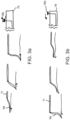
- Fig. 3
- One distal ring structure embodiment (9a) example in the active configuration
- Fig. 3a
- Adaptative mechanism of the one distal ring structure embodiment
- Fig. 3b
- Retraction mechanism of the one distal ring structure embodiment
- Fig. 4
- Movable proximal funnel embodiment (4)
- Fig. 4a
- Movable funnel in the not active configuration (funnel downstream)
- Fig. 4b
- Movable funnel in the active configuration (funnel reverted inside main body)
- Fig. 5
- Fixed funnel embodiment (4) example, with a "8" shaped proximal structure (10)
- Fig. 6
- Fixed funnel embodiment (4), with a ring shaped proximal structure (10)
- Fig. 7a
- Distal closure mechanism (15) example
- Fig. 7b
- Proximal closure mechanism (14) example
- Fig. 8
- Rings configuration examples
- Fig. 9
- Integration of the movement mechanisms for distal structure (9b) and funnel (4)
- Fig. 10
- Trackability and Navigation tools example: external shaft (13), radiopaque marker (19) and tip (17)
- Fig. 11a-g
- Method for embolic protection: an intra-aortic procedure example
- Fig. 11a
- Ascending aorta with guide wire (29)
- Fig. 11b
- Navigation of the collapsed filter device (1) along the aortic arch (25)
- Fig. 11c
- Device deployment at the intended location
- Fig. 11d
- Interaction between the device, pig tail and other working catheters (31)
- Fig. 11e
- Emboli entrapment and Blood Flow direction through the device
- Fig. 11f
- Proximal (14) and distal closure (15) activation
- Fig. 11g
- Filter device retrieved after procedure
- Fig. 12a-d
- Different filter examples with a funnel configuration defined by one or more stitching lines
-
- 1
- transcatheter filter device
- 2
- tubular filter
- 3
- main body of the tubular filter
- 4
- funnel
- 5
- distal end of the tubular filter
- 6
- proximal end of the tubular filter
- 7
- port of the tubular filter (coincident with the funnel apex)
- 8
- structure assembly
- 9
- distal structure
- a. embodiment with one ring
- b. embodiment with two rings assembly
- 10
- proximal structure
- 11
- supporting catheter
- 12
- filter-structure-catheter assembly
- 13
- external shaft
- 14
- proximal closure system
- a. self-sealing automatic closure mechanism (a-a; a-b: two different embodiments)
- b. mechanical closure mechanism (b1 open; b2 closed)
- 15
- distal closure system
- 16
- handle and relevant commands, which can comprise the following elements:
- a. command for external shaft (13) movement
- b. command for distal structure (9) trim
- c. command for funnel (4) movement
- d. command for proximal port (7) activation
- e. command for distal port (7) activation
- f. flushing port for guide wire (29)
- g. flushing port for external shaft (13)
- 17
- tip
- 18
- artificial valve
- 19
- radiopaque markers
-
- 20
- Aortic valve
- 21
- Coronary ostia
- 22
- Sinu Tubular Junction
- 23
- Ascending aorta
- 24
- Innominate artery
- 25
- Aortic arch
- 26
- Descending aorta
- 27
- Femoral access
-
- 28
- Introducer
- 29
- Guidewire
- 30
- Pigtail
- 31
- Working catheter
- 32
- Funnel lower stitching line
- 33
- Funnel upper stitching line
- 34
- Intermediate structure (example A)
- 35
- Intermediate structure (example B)
- In one embodiment, the antiembolic filter device comprises the following macro elements (
Fig. 1 ): an assembly 12, which includes atubular filter 2 adapted to retain emboli, whilst allowing blood flow, astructure assembly 8 to sustain the filter and make it couple with a vessel, anexternal shaft 13 to collapse / track / deploy / retrieve said assembly and ahandle 16 to enable with specific commands said operations, together with the optimal sealing with the vessel and the interaction with other devices. - The
tubular filter 2 is placed externally to thestructure assembly 8, as shown inFig. 1 : this assembly comprises adistal support structures 9, placed upstream respect to the blood flow direction and intended to make a leak-free coupling of the filter with the vessel, aproximal support structure 10, defining the region where the emboli are collected and where other devices pass inside the filter by crossingrelevant port 7, and a supportingcatheter 11, as shown inFig. 1c . In specific embodiments, saidtubular filter 2,structure assembly 8,external shaft 13 and handle 16 are permanently joined. - In specific embodiments (
Fig. 2 ,3 ), said filter device is adapted to be used as an intra-aortic protection, extending from the ascendingaorta 23, upstream with respect to theinnominate artery 24, to the descendingaorta 26. -
Fig. 1a show the main components of said filter device 1 here below described starting from thetubular filter 2 components, then going to thestructure 8,shaft 13, handle 16. - The
tubular filter 2 is preferably made of a low friction porous and flexible polymeric or composite material, here including polyester or polyamide, with mesh pore preferably lower than 150 microns. It can be coated with either a hydrophilic, low friction or anti-thrombogenic coating or a combination of thereof. Filter material, coating and shape facilitate the navigation of transcatheter devices into its body, both during the insertion and the retrieval, preventing relevant direct contact with the vessel wall, that can make injuries on it. Specific embodiments comprise perforated membranes and fabrics. In one embodiment a woven fabric can be chosen, with warp and weft either made by multifilament or monofilament yarn, with an either constant or variable weaving pattern, thus resulting in a pore comprised amongst the square and the circular geometry and either constant or variable mesh pore and open area along the filter longitudinal and circumferential directions. - The
tubular filter 2 is geometrically defined by a distal element and a proximal element, namely amain body 3 and a funnel 4 (Fig. 1a ). Themain body 3 comprises adistal end 5 and aproximal end 6; saiddistal end 5 is adapted to be open when the device is in active configuration, hermetically coupled with the vessel and closed before the device retraction; saidproximal end 6 that is adapted to be open in the active configuration; saidfunnel 4 forming an extension of saidmain body 3, with the funnel base located at said proximal end (6). - Embodiments for the filter main body 3 (
Fig1b ) include a cylindrical body, a conical body and combination thereof. Specific embodiments for intra-aortic procedures comprise a three regions main body 3e (Fig. 1b ), with a distal cylindrical part coupling with the aorta 3-1, an intermediate conical part 3-2 having a progressively decreasing diameter and a proximal cylindrical part 3-3, with: said intermediate part shaped to reduce relevant pressure drop for blood circulation and the overall filter encumbrance along the internal side of theaortic arch 25; said proximal cylindrical part geometry intended to allow free forward and back movement of working catheters, even in case of retrieve of partially re-collapsed TAVIs in descending aorta. The length of the main body is generally comprised from 10 to 30 cm, in order to be adapted to extend for all the vessel length to be protected from the ascendingaorta 23, upstream with respect to theinnominate artery 24, to the descendingaorta 26. - Embodiments for the
funnel 4 include movable and fixed funnels, with either symmetric or asymmetric shapes. -
Figure 4 shows an embodiment of amovable funnel 4, with funnel in its extreme configurations: a first position (detailed inFig 4b ), in which the funnel apex is proximal with respect tomain body 3 proximalopen end 6 and a second position (detailed inFig 4a ), in which the funnel apex is positioned within said main body, between saidmain body 3 distal and proximal ends. In the active configuration, the funnel top is generally positioned inside the main body, thus acting as a sliding conveyor for working catheters that cross it, whilst gathering the emboli in the interspace amongst the main body and thefunnel 4c, this making the interaction between the working catheter and the funnel port intrinsically free from emboli. In this embodiment, the funnel is oriented by acting on the apex, i.e. with a push-pull system commanded by the handle as detailed inFig. 4b and 4a , this embodiment allowing to move the funnel also whilst a working catheter crosses it. - A second embodiment for the funnel (
Fig 5 ) comprises a fixed funnel element with distal apex 4-2, enabling the crossing of working catheters, joined to the following elements: laterally, to a fixed conical element, being the proximal part of themain body 3, with proximal apex 4-1 adapted to collect emboli; to aproximal ring 10, shaped as a "8", that defines the base of the funnel and of the collecting conical element; to a flap 4-3, with distal end base either connected to the filtermain body 3 or to the supportingcatheter 11 and proximal end connected at least in a single point to the funnel 4-2, this flap adapted to prevent emboli release downstream, whilst allowing the funnel to be crossed. - In a third embodiment for the funnel (
Fig. 6 ), it comprises an orientation fixed funnel element with the base open at the proximal end in the active configuration, acting as a conveyor; this funnel being joined to at least the following elements: laterally, to a fixed conical element, being the proximal part of themain body 3, with the apex closed at the proximal end; to a radially expandable proximal structure (10), said proximal structure either being manually activated or self-expandable. - The funnel element is generally positioned in a straight portion of the vessel, in order to ensure easy crossing of working catheters at its apex. The funnel is shorter than main body, with a ratio of the funnel to main body length is generally comprised between 1/10 and 1/3, depending on the specific vessel centerline length, shape and vessel diameter. Specific intra-aortic embodiments have a funnel length generally comprised between 2 and 10 cm.
- The
proximal closure system 14 preventing downstream emboli release, which is positioned at thefunnel 4 apex is referred as the filterproximal port 7: it can either consists of a funnel geometry shaped in order to have the apex oriented downstream respect to the blood flow or consists of a folded top or a combination of thereof systems or consists of an actual closure system; an example of closure system is constructed by a lazoo system activated by a wire, either manually 14b or automatically 14a, thanks to an elastic wire.Fig. 7b shows examples of proximal port applied to a movable funnel systems: in the two pictures at the top, a mechanical closure mechanism is shown in the open b1 and closed b2 positions, whilst in the two pictures at the bottom two different self-sealing automatic closure embodiments are shown a-a; a-b. - The
distal closure system 15, used to prevent upstream dislodgement at the end of the procedure, is activated before recollapsing the device (Fig 7a ), being either a lazoo system, manually activated, or an automatic elastic system, which is manually deactivated in the active configuration. - A specific embodiment of the
support structure assembly 8 is shown inFig. 1c ; it comprises at least: a supportingcatheter 11 extending within the main body, one radially expandabledistal structure 9 joined to said main body distal end, one radially expandableproximal structure 10 positioned at said main body proximal end level, saiddistal structure 9 and saidproximal structure 10 being fixed to said supportingcatheter 11. -
Fig. 2 andFig. 3 show two intra-aortic embodiments of the filter device 1 in the active configuration, differing on thedistal structure 9 element. In both cases, the mechanical stability of the filter device, either in a standalone condition or when crossed by other working catheters, is ensured at least by the coupling of thedistal structure 9 with the ascending aorta vessel and by the coupling of the supportingcatheter 11 with the aortic arch. - The radial expandable characteristics of the distal structure ensure to cover a broad range of geometry (with ascending aorta diameter usually ranging between 20 and 40 mm) and anatomies with a reduced number of sizes for the filter device without risk of device dislodgment or migration.
- In the specific embodiment shown in
Fig.2 , the distal 9 structure comprises tworings elements 9b, here referred as the more proximal and the more distal elements, mutually joined: the more distal ring element is joined to thecatheter 11 at its distal end, to the more proximal ring element at its proximal end and to the distal end of themain body 3 along its perimeter; the more proximal element is connected at its proximal end to a specific handle sealing command by a rod, passing inside a lumen of the supportingcatheter 11. This structure can be either constructed of a single wire or multiple wires having either a circular, elliptical or rectangular section, or a combination thereof; the joinings amongst the components can be made by crimping, welding, gluing, binding or, in case of wire elements by twisting them, or with a combination of thereof methods. - The distal ring element is designed to radially expand conforming to the aorta in the active configuration, thus guaranteeing a leak-free coupling: this is ensured by the high elasticity limit of the material used, preferably but not exclusively being Nitinol, by its geometry, with perimeter larger than the aorta vessel, by relevant axis free orientation, tilted respect to aorta centerline and by relevant deformation mechanisms commanded by the handle. As an example, by actively pushing on the sealing handle command (forward movement on the
command 16b:Fig 2a ), the proximal ring element pushes onto the distal one, thus partially tilting relevant ring plane and resulting in radial compression onto the aortic wall. In this embodiment the pulling handle command (backward movement on thecommand 16b:Fig 2b ) can be adopted in order to close the filter main body distal end without using specific commands. In a further specific configuration, which is shown inFig. 9 , the interconnection amongst distal ring and funnel commands can act simultaneously on the closure mechanism of the filter distal end and on the movement of the funnel apex, thus simplifying the handle mechanism and the operations to be carried out prior to the device retrieve. - In the embodiment shown in
Fig.3 , the distal 9 structure comprises onering element 9a, with proximal end joined to thecatheter 11, perimeter joined at the distal end of themain body 3, distal end joined to a single or multiple wire passing inside the filter and connected to a specific handle sealing command. In this case the radial expansion of the ring (Fig 3a ), for which apply considerations similar to the distal ring element referred inFig. 2a , is ensured by a pulling system rather than a pushing system command. - A specific embodiment of the
proximal structure 10 is shown inFig. 4 , with structure shaped as a ring and connected to the supporting catheter. The ring defines the base of thefunnel 4, allowing to orient it either in the proximal and distal directions, by tilting its apex by specific commands connected to the handle. In the embodiment shown, the ring doesn't couple with the descending aorta. In other embodiments theproximal structure 10 can be shaped similarly respect to thedistal structure 9, thus allowing to radially couple with the aorta vessel. - Specific embodiments can be constructed wherein structures intermediate respect to the distal 9 and proximal 10 can be connected to the supporting
catheter 11, in order to increase the device stability and contribute to fully expand the tubular filter main body. - For both the distal and proximal, and where applicable intermediate, structures, the overall geometry can be elliptical in plan view, but also differently shaped as shown in
Fig. 8 ; similarly, lateral view can show a planar structure but also a "S" shaped lateral profile to enhance leak-free conforming to the aortic arch, as shown inFig. 8 . - The supporting
catheter 11, which is joined to the distal 9 and proximal 10 structures and to thetubular filter 2, adapts in the active configuration at the extrados of the aortic arch and sustains all the loads arising from the procedure (seeFig. 11 ): at this purpose it can be made by a flexible polymeric or a composite material, here including a metal braided polymer, selected as the best compromise amongst high elongation / compression / torsion stiffness and fairly high flexibility. The supportingcatheter 11 profile is adapted to house inside specific lumens, the commands to crimp / deploy thefilter 2, to act on the distal 9 and proximal 10 structures and on the distal and proximal filter closure system, where applicable, and to house other accessories / working catheters, here including guide-wire, pig-tail and balloon catheters, here contributing to simplify the overall procedure. - The
external shaft 13, see details inFig. 10 and11 , is adapted to guide the collapsed filter assembly 12 in position and to allow the deployment/recapture of the device, by sliding backward and forward respect to the multilumen catheter. Theexternal shaft 13 is made of a flexible polymeric or composite material and preferably a metal braided polymer, i.e with reduced tensile and compression elongation and with adequate flexural compliance to ensure optimal pushability when tracking the filter device along the aortic arch, thus allowing to adapt to the extrados curvature of aorta without forcing onto it and minimizing snacking whilst interacting with the supporting catheter to crimp / deploy the filter. - A
tip 17 can be included in any of the saidstructures external shaft 13 or other structures to allow adequate priming, easy crossing of the introducer and smooth navigation into the aorta (Fig.2 andFig.10 ). -
Radiopaque markers 19, see details inFig.10 ,Fig.11b , can be joined tospecific locations - The handle 16 (
Fig.1a ) allows specific commands including, where applicable, the sliding between anexternal shaft 13 and the supportingcatheter 11, thus allowing filter crimping ordeployment 16a, the activation of the distal closure mechanism 16e, the activation of proximal 14: 16d and distal 15: 16e closure mechanisms, the tensioning of the distal support structure 9: 16b, the funnel movement 16c, the flushing of the ports for guide wire 16f andexternal shaft 16g, the direct loading of other devices or accessories, not limited to a guide wire and / or a pig tail catheter and the enabling / disabling of an artificial valve 18, where applicable. The handle structure is made preferably but not exclusively by polymeric material; it houses all the commands, either made by rods or wires, and the proximal terminations of the supportingcatheters 11 and of theexternal shaft 13, either directly or with the interposition of metal tubes. The handle can adopt either linear / rotatory mechanism to allow said movements and block systems, where applicable, to fix it in a determined position. - Here below a transcatheter procedure, not part of the invention, adopting the antiembolic filter device 1 is detailed, with specific features referring to an intra-aortic procedure, here comprising a TAVI, which allow cerebral and systemic emboli protection.
- In this example, the antiembolic filter device 1 access is made from the femoral artery opposite (secondary) to that one (main) accessed by the working
catheter 31 used for the prosthesis or the device to treat the aortic valve (Fig.11d ). Here below relevant procedure details: - a) An
introducer 28 is inserted inside afemoral access 27. - b) A
guide wire 29 is inserted inside theintroducer 28 and navigated up to the aortic arch (Fig. 11a ). As an option a pigtail is inserted and navigated up to the ascending aorta to allow a fluoroscopic imaging reference prior to the filter device insertion. - c) The filter device is collapsed, primed and debubbled into the
external shaft catheter 13 before to introduce it into the arterial vessel (Fig. 11b ). - d) The device is tracked along the vessel and positioned, with the aid of radiopaque markers and adequate imaging technique, the upstream respect to the
innominate artery 24; the device is deployed and coupled with ascending aorta, by retracting the external shaft catheter 13 (Fig. 11c ). - e) When the device is deployed, the distal end of the
Filter 5 is fitting the aortic wall in order to convey all blood and possible debris into its funnel (Fig.11e ) thanks to thesupport structure 9, which circumferentially push thedistal filter surface 5 against the aortic wall. - f) It is now possible to introduce the other working catheters inside the filter by crossing the
funnel 4, whilst thefunnel 4 andport 7 configuration prevents forward debris dislodgment.Fig.11d shows the interaction amongst filter device and other working catheters normally used in a TAVI procedure. - g) At the end of the procedure the distal end of the
filter 5, which in the expanded configuration remains open, can be closed, before the device recollapsing, in order to prevent any upstream debris dislodgment of the emboli collected at the proximal end of the device (Fig.11f ). - h) The device is completely re-collapsed by pushing distally the
external shaft catheter 13, as shown inFig. 11g . In this way, the device structures gradually collapse until reaching the distal end of the device safely keeping inside it all captured clots or calcium debris. - i) Finally, the overall device is retrieved.
- Specific procedures can require partial closure, repositioning and re-deployment at different levels (e.g. from sinotubular junction to descending aorta) and, eventually, different supporting catheter positioning.
- Moreover, procedures different respect to intra-aortic ones can require different geometrical arrangements of the above-mentioned concepts, therefore this filter device can be applied in principle in any arterial or venous system requiring an antiembolic protection.
- This method allows to deploy the filter device prior to the other working
catheters 31, seeFig.11d , and retrieve it after all the other working catheters, thus enabling to: - a) collect and retain emboli released during transcatheter procedures, with working devices eventually moving along the filter;
- b) track working catheters inside the filter without direct contact to the vessel wall;
- c) have the
proximal port 14 of the filter generally closed during the whole procedure and thedistal port 15 closed before the filter device is recollapsed and retrieved, thus preventing any downstream and upstream emboli release (Fig.11f ). -
Figures 12a to 12d show different configurations of thefunnel 4 and of a dead end to capture emboli generated during a procedure. The delimitation of thefunnel 4 inFig. 12 a is obtained with twostitching lines tubular filter 2. In particular theupper stitching line 33 is running all along thecatheter body 11. The space between theupper stitching line 33 and thesupport 11 is dedicated to thedistal structure 9b. - In another embodiment (
Fig. 12b ) thefunnel 4 is delimited as in the embodiment ofFig. 12a while buttubular filter 2 furthermore contains anintermediate structure 34 for capturing emboli. Theintermediate structure 34 has a conical shape defined between twostitching lines 32',32". The basis of the conical shape is located on the distal side and forms an emboli inflow mouth made by a rigid ring. -
Figure 12c describes a solution similar toFig. 12a in which the distal port of thefunnel 4 is arigid ring 7. - In the embodiment of
figure 12d , thetubular filter 2 contains a "8" shape element made of two rigids rings, wherein theupper ring 7 forms thefunnel 4 distal port and wherein the lower ring forms the basis of an emboli capturingintermediate structure 35.
Claims (16)
- An intra-vessel transcatheter filter device (1) designed to capture and remove emboli, thus preventing distal embolization, comprising:• a tubular filter (2) comprising a flexible porous material and defined by a distal element and a proximal element, namely a main body (3) and a funnel (4);i. said main body (3) having a length adapted to extend within a suitable vessel zone; said main body (3) comprising:a) a distal end (5) that is adapted to be radially coupled with said zone and hermetically sealed to it when the device is in an active configuration, said distal end (5) being provided of selectively actionable closure means so that said distal end is designed to be open when the device is in an active configuration and closed before the device retraction,b) a proximal end (6);ii. said funnel (4) forming an extension of said main body (3), with the funnel base located at said proximal end (6).• a support structure assembly (8) comprising:characterized in that the supporting catheter (11) is joined to said distal structure (9) and said proximal structure (10).i. a supporting catheter (11) extending within said main body (3),ii. one radially expandable distal structure (9) fixed to said distal end (5),iii. one radially expandable proximal structure (10) positioned in correspondence of said proximal end (6),
- Device according to claim 1 wherein the supporting catheter (11) is joined to the tubular filter (2).
- Device according to claims 1 or 2 wherein the funnel (4), having substantially the same cross-section area of the main body (2), is movable with respect to the main body (3), between a first position in which the funnel top is positioned outside said main body (3) and a second position in which the funnel top is positioned within said main body (3), between said distal end (5) and said proximal end (6).
- Device according to claims 1 or 2 wherein the funnel (4) is fixed with respect to the main body (3), with the funnel top being permanently positioned within said main body (3), between said distal end (5) and said proximal end (6).
- Device according to anyone of the previous claims wherein the porosity of said flexible porous mesh material of the filter (2) is lower than 150 micron, and preferably between 40 and 70 microns.
- Device according to anyone of the previous claims wherein said distal (5) and proximal (6) ends are both provided of selectively actionable closure mechanisms.
- Device according to anyone of the previous claims wherein the filter is made of a low friction and flexible polymeric or composite material, preferably but not exclusively a fabric.
- Device according to anyone of the previous claims wherein the filter is coated with either a hydrophilic, low friction or anti-thrombogenic coating or a combination of thereof.
- Device according to anyone of the previous claims wherein the distal (9) and proximal (10) structures have a ring shape.
- Device according to claim 9 wherein at least one of the said structures (9, 10) comprises two rings that are mutually joined.
- Device according to anyone of the previous claims wherein the distal structure (9) is part of said selectively actionable closure mechanisms.
- Device according to anyone of the previous claims wherein the funnel (4) apex is provided with a catheter access port, so that the funnel (4) is designed to act as a conveyor for working catheters that cross it.
- Device according to anyone of the previous claims wherein said catheter (11) is adapted to track inside relevant lumen other working catheters or instruments, whilst allowing emboli retaining, the device having a geometry adapted to intra-vessel procedures and length of the filter main body adapted to extend within a suitable vessel zone, e.g. for intra-aortic procedures generally comprised between 10 cm and 30 cm in order to be adapted to extend from the ascending aorta (23) to the descending aorta (26).
- Device according to anyone of the previous claims comprising an artificial valve (18).
- Device according to anyone of the previous claims comprising an intermediate structure (34,35) containing a dead end, said intermediate structure (34, 35) being adapted to capture emboli transported by the blood flow.
- Device according to anyone of the previous claims wherein said tubular filter (2) comprises one or several stitching lines that define specific areas such as said funnel (4), a intermediate structure (34, 35) with a dead end or a channel for said distal structure (9).
Applications Claiming Priority (2)
| Application Number | Priority Date | Filing Date | Title |
|---|---|---|---|
| EP19167599.0A EP3718505A1 (en) | 2019-04-05 | 2019-04-05 | Transcatheter anti embolic filter for arterial and venous vessels |
| PCT/EP2020/059601 WO2020201524A1 (en) | 2019-04-05 | 2020-04-03 | Transcatheter anti embolic filter for arterial and venous vessels |
Publications (3)
| Publication Number | Publication Date |
|---|---|
| EP3946146A1 EP3946146A1 (en) | 2022-02-09 |
| EP3946146C0 EP3946146C0 (en) | 2024-06-05 |
| EP3946146B1 true EP3946146B1 (en) | 2024-06-05 |
Family
ID=66101957
Family Applications (2)
| Application Number | Title | Priority Date | Filing Date |
|---|---|---|---|
| EP19167599.0A Withdrawn EP3718505A1 (en) | 2019-04-05 | 2019-04-05 | Transcatheter anti embolic filter for arterial and venous vessels |
| EP20720905.7A Active EP3946146B1 (en) | 2019-04-05 | 2020-04-03 | Transcatheter anti embolic filter for arterial and venous vessels |
Family Applications Before (1)
| Application Number | Title | Priority Date | Filing Date |
|---|---|---|---|
| EP19167599.0A Withdrawn EP3718505A1 (en) | 2019-04-05 | 2019-04-05 | Transcatheter anti embolic filter for arterial and venous vessels |
Country Status (5)
| Country | Link |
|---|---|
| US (1) | US12465477B2 (en) |
| EP (2) | EP3718505A1 (en) |
| JP (1) | JP7485383B2 (en) |
| CN (1) | CN113660915B (en) |
| WO (1) | WO2020201524A1 (en) |
Cited By (1)
| Publication number | Priority date | Publication date | Assignee | Title |
|---|---|---|---|---|
| EP3946146B1 (en) | 2019-04-05 | 2024-06-05 | Aorticlab Srl | Transcatheter anti embolic filter for arterial and venous vessels |
Families Citing this family (15)
| Publication number | Priority date | Publication date | Assignee | Title |
|---|---|---|---|---|
| EP3403615A1 (en) | 2017-05-17 | 2018-11-21 | Aorticlab Sarl | Transcatheter valve prosthesis for blood vessel |
| WO2019053538A1 (en) | 2017-09-12 | 2019-03-21 | Aorticlab Sarl | Transcatheter device for the treatment of calcified heart valve leaflets |
| US12109102B2 (en) | 2017-09-28 | 2024-10-08 | Zeev Brandeis | Aortic protection |
| CN113286552B (en) | 2018-11-28 | 2025-05-02 | 希斯托索尼克斯公司 | Tissue destruction system and method |
| JP2023530477A (en) | 2020-06-18 | 2023-07-18 | ヒストソニックス,インコーポレーテッド | Tissue-tripping acoustic/patient coupling system and method |
| EP4204084A4 (en) | 2020-08-27 | 2024-10-09 | The Regents Of The University Of Michigan | Ultrasound transducer with transmit-receive capability for histotripsy |
| IL308943A (en) | 2021-06-07 | 2024-01-01 | Univ Michigan Regents | All-in-one ultrasound systems and methods including histotripsy |
| EP4351718A4 (en) | 2021-06-07 | 2025-03-26 | The Regents of The University of Michigan | Minimally invasive histotripsy systems and methods |
| CN116138922A (en) * | 2021-11-19 | 2023-05-23 | 上海蓝帆博奥医疗科技有限公司 | thrombus filter device |
| CN116138923A (en) * | 2021-11-19 | 2023-05-23 | 上海蓝帆博奥医疗科技有限公司 | thrombus filter device |
| CN113952074B (en) * | 2021-11-25 | 2025-03-07 | 苏州希尔医疗科技有限公司 | Embolic protection and collection device |
| US20230381490A1 (en) * | 2022-05-26 | 2023-11-30 | Excision Medical, Inc. | Surgical system for managing blood flow during a surgical procedure |
| EP4577153A1 (en) * | 2022-08-25 | 2025-07-02 | Zeev Brandeis | Fixation of debris protection devices in body lumens |
| AU2023366591A1 (en) | 2022-10-28 | 2025-04-24 | Histosonics, Inc. | Histotripsy systems and methods |
| WO2024221001A2 (en) | 2023-04-20 | 2024-10-24 | Histosonics, Inc. | Histotripsy systems and associated methods including user interfaces and workflows for treatment planning and therapy |
Citations (11)
| Publication number | Priority date | Publication date | Assignee | Title |
|---|---|---|---|---|
| WO2001097714A1 (en) | 2000-06-23 | 2001-12-27 | Salviac Limited | Filter element for embolic protection device |
| WO2003047648A2 (en) | 2001-12-05 | 2003-06-12 | Sagax Inc. | Endovascular device for entrapment of particulate matter and method for use |
| US20040215167A1 (en) | 2002-08-27 | 2004-10-28 | Amir Belson | Embolic protection device |
| US20060287668A1 (en) | 2005-06-16 | 2006-12-21 | Fawzi Natalie V | Apparatus and methods for intravascular embolic protection |
| WO2008066881A1 (en) | 2006-11-29 | 2008-06-05 | Amir Belson | Embolic protection device |
| WO2013103979A1 (en) | 2012-01-06 | 2013-07-11 | Emboline, Inc. | Integrated embolic protection devices |
| WO2014059005A1 (en) | 2012-10-09 | 2014-04-17 | Boston Scientific Scimed, Inc. | Special opening aortic embolic protection device for structural heart procedures |
| US20140257362A1 (en) | 2013-03-07 | 2014-09-11 | St. Jude Medical, Cardiology Division, Inc. | Filtering and removing particulates from bloodstream |
| WO2017116828A1 (en) | 2015-12-29 | 2017-07-06 | Emboline, Inc. | Multi-access intraprocedural embolic protection device |
| US10130331B2 (en) | 2013-03-15 | 2018-11-20 | Volcano Corporation | Distal protection systems and methods with pressure and ultrasound features |
| EP3946146B1 (en) | 2019-04-05 | 2024-06-05 | Aorticlab Srl | Transcatheter anti embolic filter for arterial and venous vessels |
Family Cites Families (23)
| Publication number | Priority date | Publication date | Assignee | Title |
|---|---|---|---|---|
| US6361545B1 (en) | 1997-09-26 | 2002-03-26 | Cardeon Corporation | Perfusion filter catheter |
| CN1775190B (en) | 1999-01-27 | 2010-06-16 | 梅德特龙尼克有限公司 | Heart valve surgery methods and devices |
| US7749245B2 (en) | 2000-01-27 | 2010-07-06 | Medtronic, Inc. | Cardiac valve procedure methods and devices |
| US6929653B2 (en) | 2000-12-15 | 2005-08-16 | Medtronic, Inc. | Apparatus and method for replacing aortic valve |
| AU2011202667B2 (en) | 2003-12-23 | 2012-09-27 | Sadra Medical, Inc. | Apparatus and methods for heart valve replacement |
| US7569071B2 (en) | 2005-09-21 | 2009-08-04 | Boston Scientific Scimed, Inc. | Venous valve, system, and method with sinus pocket |
| EP2117468A1 (en) | 2007-02-05 | 2009-11-18 | Boston Scientific Limited | Systems and methods for valve delivery |
| EP2120737B1 (en) * | 2007-02-05 | 2020-04-01 | Boston Scientific Limited | Thrombectomy apparatus |
| US8372108B2 (en) | 2009-01-16 | 2013-02-12 | Claret Medical, Inc. | Intravascular blood filter |
| WO2012021527A2 (en) | 2010-08-09 | 2012-02-16 | Valvexchange, Inc. | Temporary sub-valvular check valve |
| US20140005540A1 (en) | 2011-01-07 | 2014-01-02 | Innovative Cardiovascular Solutions, Inc. | Angiography Catheter |
| EP2522307B1 (en) | 2011-05-08 | 2020-09-30 | ITSO Medical AB | Device for delivery of medical devices to a cardiac valve |
| US20130096606A1 (en) * | 2011-10-17 | 2013-04-18 | William C. Bruchman | Embolic protection devices and related systems and methods |
| WO2014117087A1 (en) | 2013-01-25 | 2014-07-31 | Apica Cardiovascular Limited | Systems and methods for percutaneous access, stabilization and closure of organs |
| US20160028236A1 (en) | 2013-03-13 | 2016-01-28 | Bunker Energy Partners, Llc | Systems and methods for generating energy using a hydrogen cycle |
| EP3060164A1 (en) | 2013-10-21 | 2016-08-31 | Innovative Cardiovascular Solutions, LLC | Embolic protection device |
| WO2015184450A1 (en) | 2014-05-30 | 2015-12-03 | Cardiac Valve Solutions Llc | Temporary valve and filter on guide catheter |
| FR3021860A1 (en) | 2014-06-05 | 2015-12-11 | Bernard Pain | TRANSCATHETER DEVICE FOR ABLATION OF CALCIFIED FABRICS AT THE LEVELS OF AN AORTIC VALVE |
| FR3021863A1 (en) | 2014-06-05 | 2015-12-11 | Bernard Pain | TRANSCATHETER INTRODUCTION DEVICE IN THE AORTIC ROOT AT THE TUBULAR SINO JUNCTION |
| CN108472119B (en) * | 2015-09-07 | 2020-08-07 | 菲尔特莱克斯医药有限公司 | Aorta internal embolus protection filter device |
| EP3403615A1 (en) | 2017-05-17 | 2018-11-21 | Aorticlab Sarl | Transcatheter valve prosthesis for blood vessel |
| WO2019053538A1 (en) | 2017-09-12 | 2019-03-21 | Aorticlab Sarl | Transcatheter device for the treatment of calcified heart valve leaflets |
| EP3685772A1 (en) | 2019-01-24 | 2020-07-29 | Aorticlab Sarl | Device for the treatment of tissue calcification |
-
2019
- 2019-04-05 EP EP19167599.0A patent/EP3718505A1/en not_active Withdrawn
-
2020
- 2020-04-03 WO PCT/EP2020/059601 patent/WO2020201524A1/en not_active Ceased
- 2020-04-03 CN CN202080027045.1A patent/CN113660915B/en active Active
- 2020-04-03 JP JP2021557526A patent/JP7485383B2/en active Active
- 2020-04-03 US US17/442,168 patent/US12465477B2/en active Active
- 2020-04-03 EP EP20720905.7A patent/EP3946146B1/en active Active
Patent Citations (11)
| Publication number | Priority date | Publication date | Assignee | Title |
|---|---|---|---|---|
| WO2001097714A1 (en) | 2000-06-23 | 2001-12-27 | Salviac Limited | Filter element for embolic protection device |
| WO2003047648A2 (en) | 2001-12-05 | 2003-06-12 | Sagax Inc. | Endovascular device for entrapment of particulate matter and method for use |
| US20040215167A1 (en) | 2002-08-27 | 2004-10-28 | Amir Belson | Embolic protection device |
| US20060287668A1 (en) | 2005-06-16 | 2006-12-21 | Fawzi Natalie V | Apparatus and methods for intravascular embolic protection |
| WO2008066881A1 (en) | 2006-11-29 | 2008-06-05 | Amir Belson | Embolic protection device |
| WO2013103979A1 (en) | 2012-01-06 | 2013-07-11 | Emboline, Inc. | Integrated embolic protection devices |
| WO2014059005A1 (en) | 2012-10-09 | 2014-04-17 | Boston Scientific Scimed, Inc. | Special opening aortic embolic protection device for structural heart procedures |
| US20140257362A1 (en) | 2013-03-07 | 2014-09-11 | St. Jude Medical, Cardiology Division, Inc. | Filtering and removing particulates from bloodstream |
| US10130331B2 (en) | 2013-03-15 | 2018-11-20 | Volcano Corporation | Distal protection systems and methods with pressure and ultrasound features |
| WO2017116828A1 (en) | 2015-12-29 | 2017-07-06 | Emboline, Inc. | Multi-access intraprocedural embolic protection device |
| EP3946146B1 (en) | 2019-04-05 | 2024-06-05 | Aorticlab Srl | Transcatheter anti embolic filter for arterial and venous vessels |
Non-Patent Citations (9)
| Title |
|---|
| ALSAIF HAIFA A, RAMADAN WAFAA S, : "An Anatomical Study of the Aortic Arch Variations", JOURNAL OF KING ABDULAZIZ UNIVERSITY-MEDICAL SCIENCES, vol. 17, no. 2, 1 January 2010 (2010-01-01), pages 37 - 54, XP093264985, ISSN: 1319-1004, DOI: 10.4197/Med.17-2.4 |
| D5c - TCT-2019-AGENDA |
| D5d - a PowerPoint version of the presentation D5a, including embedded videos (submitted as a hard copy) |
| D5d - TCT homepage dated 25.09.2019 providing a link to the presentation - https://www.tctmd.com/slide/innovative-protected-transcatheter-aortic-valvecalcium-debridement-system-aorticlab |
| D5e - Images extracted from the animation embedded in the presentation E5b |
| D5f - Photos taken at the TCT2019 presentation by Scott Russel, CEO of Emboline |
| D5g - The CV of Mr. Scott Russel |
| MUZAMIL HUSSAIN: "Ultra-High-Molecular-Weight-Polyethylene (UHMWPE) as a Promising Polymer Material for Biomedical Applications: A Concise Review", POLYMERS, MOLECULAR DIVERSITY PRESERVATION INTERNATIONAL (M DP I) AG., CH, vol. 12, no. 2, CH , pages 323, XP093165433, ISSN: 2073-4360, DOI: 10.3390/polym12020323 |
| SCALISE FILIPPO: "AorticLab solution for calcific aortic valve : Innovative Protected Transcatheter Aortic Valve Calcium Debridement System (AorticLab)", TCT 2019, TCT, AORTIC LAB, 25 September 2019 (2019-09-25), pages 1 - 13, XP093264982, Retrieved from the Internet <URL:https://www.tctmd.com/slide/innovative-protected-transcatheter-aortic-valve-calcium-debridement-system-aorticlabhttps://d14d5nk8lue86f.cloudfront.net/s3fs-public/2019-09/ADCBE8C4-DDE7-43CE-9763-B978079A2618.pdf> |
Cited By (1)
| Publication number | Priority date | Publication date | Assignee | Title |
|---|---|---|---|---|
| EP3946146B1 (en) | 2019-04-05 | 2024-06-05 | Aorticlab Srl | Transcatheter anti embolic filter for arterial and venous vessels |
Also Published As
| Publication number | Publication date |
|---|---|
| EP3946146C0 (en) | 2024-06-05 |
| CN113660915A (en) | 2021-11-16 |
| EP3718505A1 (en) | 2020-10-07 |
| EP3946146A1 (en) | 2022-02-09 |
| CN113660915B (en) | 2025-10-21 |
| US12465477B2 (en) | 2025-11-11 |
| US20220168087A1 (en) | 2022-06-02 |
| JP7485383B2 (en) | 2024-05-16 |
| WO2020201524A1 (en) | 2020-10-08 |
| JP2022526955A (en) | 2022-05-27 |
| CA3130859A1 (en) | 2020-10-08 |
Similar Documents
| Publication | Publication Date | Title |
|---|---|---|
| EP3946146B1 (en) | Transcatheter anti embolic filter for arterial and venous vessels | |
| US20230047943A1 (en) | Vascular filters, deflectors, and methods | |
| US12097108B2 (en) | Systems and methods for protecting the cerebral vasculature | |
| US10881496B2 (en) | Embolic protection during percutaneous heart valve replacement and similar procedures | |
| US11559396B2 (en) | Transcatheter valve prosthesis for blood vessel | |
| US11351023B2 (en) | Systems and methods for protecting the cerebral vasculature | |
| US20240366357A1 (en) | Systems and methods for protecting the cerebral vasculature | |
| CA3130859C (en) | Transcatheter anti embolic filter for arterial and venous vessels | |
| CA3062508C (en) | Transcatheter valve prosthesis for blood vessel |
Legal Events
| Date | Code | Title | Description |
|---|---|---|---|
| STAA | Information on the status of an ep patent application or granted ep patent |
Free format text: STATUS: UNKNOWN |
|
| STAA | Information on the status of an ep patent application or granted ep patent |
Free format text: STATUS: THE INTERNATIONAL PUBLICATION HAS BEEN MADE |
|
| PUAI | Public reference made under article 153(3) epc to a published international application that has entered the european phase |
Free format text: ORIGINAL CODE: 0009012 |
|
| STAA | Information on the status of an ep patent application or granted ep patent |
Free format text: STATUS: REQUEST FOR EXAMINATION WAS MADE |
|
| 17P | Request for examination filed |
Effective date: 20211028 |
|
| AK | Designated contracting states |
Kind code of ref document: A1 Designated state(s): AL AT BE BG CH CY CZ DE DK EE ES FI FR GB GR HR HU IE IS IT LI LT LU LV MC MK MT NL NO PL PT RO RS SE SI SK SM TR |
|
| STAA | Information on the status of an ep patent application or granted ep patent |
Free format text: STATUS: EXAMINATION IS IN PROGRESS |
|
| DAV | Request for validation of the european patent (deleted) | ||
| DAX | Request for extension of the european patent (deleted) | ||
| 17Q | First examination report despatched |
Effective date: 20220705 |
|
| GRAP | Despatch of communication of intention to grant a patent |
Free format text: ORIGINAL CODE: EPIDOSNIGR1 |
|
| STAA | Information on the status of an ep patent application or granted ep patent |
Free format text: STATUS: GRANT OF PATENT IS INTENDED |
|
| INTG | Intention to grant announced |
Effective date: 20240104 |
|
| GRAS | Grant fee paid |
Free format text: ORIGINAL CODE: EPIDOSNIGR3 |
|
| GRAA | (expected) grant |
Free format text: ORIGINAL CODE: 0009210 |
|
| STAA | Information on the status of an ep patent application or granted ep patent |
Free format text: STATUS: THE PATENT HAS BEEN GRANTED |
|
| AK | Designated contracting states |
Kind code of ref document: B1 Designated state(s): AL AT BE BG CH CY CZ DE DK EE ES FI FR GB GR HR HU IE IS IT LI LT LU LV MC MK MT NL NO PL PT RO RS SE SI SK SM TR |
|
| REG | Reference to a national code |
Ref country code: CH Ref legal event code: EP |
|
| REG | Reference to a national code |
Ref country code: DE Ref legal event code: R096 Ref document number: 602020032160 Country of ref document: DE |
|
| REG | Reference to a national code |
Ref country code: IE Ref legal event code: FG4D |
|
| U01 | Request for unitary effect filed |
Effective date: 20240626 |
|
| U07 | Unitary effect registered |
Designated state(s): AT BE BG DE DK EE FI FR IT LT LU LV MT NL PT RO SE SI Effective date: 20240902 |
|
| PG25 | Lapsed in a contracting state [announced via postgrant information from national office to epo] |
Ref country code: HR Free format text: LAPSE BECAUSE OF FAILURE TO SUBMIT A TRANSLATION OF THE DESCRIPTION OR TO PAY THE FEE WITHIN THE PRESCRIBED TIME-LIMIT Effective date: 20240605 |
|
| PG25 | Lapsed in a contracting state [announced via postgrant information from national office to epo] |
Ref country code: GR Free format text: LAPSE BECAUSE OF FAILURE TO SUBMIT A TRANSLATION OF THE DESCRIPTION OR TO PAY THE FEE WITHIN THE PRESCRIBED TIME-LIMIT Effective date: 20240906 |
|
| PG25 | Lapsed in a contracting state [announced via postgrant information from national office to epo] |
Ref country code: ES Free format text: LAPSE BECAUSE OF FAILURE TO SUBMIT A TRANSLATION OF THE DESCRIPTION OR TO PAY THE FEE WITHIN THE PRESCRIBED TIME-LIMIT Effective date: 20240605 |
|
| PG25 | Lapsed in a contracting state [announced via postgrant information from national office to epo] |
Ref country code: NO Free format text: LAPSE BECAUSE OF FAILURE TO SUBMIT A TRANSLATION OF THE DESCRIPTION OR TO PAY THE FEE WITHIN THE PRESCRIBED TIME-LIMIT Effective date: 20240905 Ref country code: HR Free format text: LAPSE BECAUSE OF FAILURE TO SUBMIT A TRANSLATION OF THE DESCRIPTION OR TO PAY THE FEE WITHIN THE PRESCRIBED TIME-LIMIT Effective date: 20240605 Ref country code: GR Free format text: LAPSE BECAUSE OF FAILURE TO SUBMIT A TRANSLATION OF THE DESCRIPTION OR TO PAY THE FEE WITHIN THE PRESCRIBED TIME-LIMIT Effective date: 20240906 Ref country code: ES Free format text: LAPSE BECAUSE OF FAILURE TO SUBMIT A TRANSLATION OF THE DESCRIPTION OR TO PAY THE FEE WITHIN THE PRESCRIBED TIME-LIMIT Effective date: 20240605 Ref country code: RS Free format text: LAPSE BECAUSE OF FAILURE TO SUBMIT A TRANSLATION OF THE DESCRIPTION OR TO PAY THE FEE WITHIN THE PRESCRIBED TIME-LIMIT Effective date: 20240905 |
|
| PG25 | Lapsed in a contracting state [announced via postgrant information from national office to epo] |
Ref country code: PL Free format text: LAPSE BECAUSE OF FAILURE TO SUBMIT A TRANSLATION OF THE DESCRIPTION OR TO PAY THE FEE WITHIN THE PRESCRIBED TIME-LIMIT Effective date: 20240605 |
|
| PG25 | Lapsed in a contracting state [announced via postgrant information from national office to epo] |
Ref country code: IS Free format text: LAPSE BECAUSE OF FAILURE TO SUBMIT A TRANSLATION OF THE DESCRIPTION OR TO PAY THE FEE WITHIN THE PRESCRIBED TIME-LIMIT Effective date: 20241005 |
|
| PG25 | Lapsed in a contracting state [announced via postgrant information from national office to epo] |
Ref country code: CZ Free format text: LAPSE BECAUSE OF FAILURE TO SUBMIT A TRANSLATION OF THE DESCRIPTION OR TO PAY THE FEE WITHIN THE PRESCRIBED TIME-LIMIT Effective date: 20240605 |
|
| PG25 | Lapsed in a contracting state [announced via postgrant information from national office to epo] |
Ref country code: SK Free format text: LAPSE BECAUSE OF FAILURE TO SUBMIT A TRANSLATION OF THE DESCRIPTION OR TO PAY THE FEE WITHIN THE PRESCRIBED TIME-LIMIT Effective date: 20240605 |
|
| PG25 | Lapsed in a contracting state [announced via postgrant information from national office to epo] |
Ref country code: SM Free format text: LAPSE BECAUSE OF FAILURE TO SUBMIT A TRANSLATION OF THE DESCRIPTION OR TO PAY THE FEE WITHIN THE PRESCRIBED TIME-LIMIT Effective date: 20240605 |
|
| PG25 | Lapsed in a contracting state [announced via postgrant information from national office to epo] |
Ref country code: SM Free format text: LAPSE BECAUSE OF FAILURE TO SUBMIT A TRANSLATION OF THE DESCRIPTION OR TO PAY THE FEE WITHIN THE PRESCRIBED TIME-LIMIT Effective date: 20240605 Ref country code: SK Free format text: LAPSE BECAUSE OF FAILURE TO SUBMIT A TRANSLATION OF THE DESCRIPTION OR TO PAY THE FEE WITHIN THE PRESCRIBED TIME-LIMIT Effective date: 20240605 Ref country code: PL Free format text: LAPSE BECAUSE OF FAILURE TO SUBMIT A TRANSLATION OF THE DESCRIPTION OR TO PAY THE FEE WITHIN THE PRESCRIBED TIME-LIMIT Effective date: 20240605 Ref country code: IS Free format text: LAPSE BECAUSE OF FAILURE TO SUBMIT A TRANSLATION OF THE DESCRIPTION OR TO PAY THE FEE WITHIN THE PRESCRIBED TIME-LIMIT Effective date: 20241005 Ref country code: CZ Free format text: LAPSE BECAUSE OF FAILURE TO SUBMIT A TRANSLATION OF THE DESCRIPTION OR TO PAY THE FEE WITHIN THE PRESCRIBED TIME-LIMIT Effective date: 20240605 |
|
| REG | Reference to a national code |
Ref country code: DE Ref legal event code: R026 Ref document number: 602020032160 Country of ref document: DE |
|
| PLBI | Opposition filed |
Free format text: ORIGINAL CODE: 0009260 |
|
| 26 | Opposition filed |
Opponent name: EMBOLINE, INC. Effective date: 20250305 |
|
| PLAX | Notice of opposition and request to file observation + time limit sent |
Free format text: ORIGINAL CODE: EPIDOSNOBS2 |
|
| PLAB | Opposition data, opponent's data or that of the opponent's representative modified |
Free format text: ORIGINAL CODE: 0009299OPPO |
|
| R26 | Opposition filed (corrected) |
Opponent name: EMBOLINE, INC. Effective date: 20250305 |
|
| U20 | Renewal fee for the european patent with unitary effect paid |
Year of fee payment: 6 Effective date: 20250425 |
|
| PLBB | Reply of patent proprietor to notice(s) of opposition received |
Free format text: ORIGINAL CODE: EPIDOSNOBS3 |
|
| TPAC | Observations filed by third parties |
Free format text: ORIGINAL CODE: EPIDOSNTIPA |
|
| REG | Reference to a national code |
Ref country code: CH Ref legal event code: H13 Free format text: ST27 STATUS EVENT CODE: U-0-0-H10-H13 (AS PROVIDED BY THE NATIONAL OFFICE) Effective date: 20251125 |
|
| PG25 | Lapsed in a contracting state [announced via postgrant information from national office to epo] |
Ref country code: MC Free format text: LAPSE BECAUSE OF FAILURE TO SUBMIT A TRANSLATION OF THE DESCRIPTION OR TO PAY THE FEE WITHIN THE PRESCRIBED TIME-LIMIT Effective date: 20240605 |
|
| GBPC | Gb: european patent ceased through non-payment of renewal fee |
Effective date: 20250403 |
|
| PG25 | Lapsed in a contracting state [announced via postgrant information from national office to epo] |
Ref country code: GB Free format text: LAPSE BECAUSE OF NON-PAYMENT OF DUE FEES Effective date: 20250403 |
|
| PG25 | Lapsed in a contracting state [announced via postgrant information from national office to epo] |
Ref country code: CH Free format text: LAPSE BECAUSE OF NON-PAYMENT OF DUE FEES Effective date: 20250430 |
|
| PG25 | Lapsed in a contracting state [announced via postgrant information from national office to epo] |
Ref country code: IE Free format text: LAPSE BECAUSE OF NON-PAYMENT OF DUE FEES Effective date: 20250403 |