EP3946104B1 - Bone anchor head converter - Google Patents
Bone anchor head converter Download PDFInfo
- Publication number
- EP3946104B1 EP3946104B1 EP20783943.2A EP20783943A EP3946104B1 EP 3946104 B1 EP3946104 B1 EP 3946104B1 EP 20783943 A EP20783943 A EP 20783943A EP 3946104 B1 EP3946104 B1 EP 3946104B1
- Authority
- EP
- European Patent Office
- Prior art keywords
- tulip head
- pedicle screw
- head
- lobe
- screw
- Prior art date
- Legal status (The legal status is an assumption and is not a legal conclusion. Google has not performed a legal analysis and makes no representation as to the accuracy of the status listed.)
- Active
Links
Images


Classifications
-
- A—HUMAN NECESSITIES
- A61—MEDICAL OR VETERINARY SCIENCE; HYGIENE
- A61B—DIAGNOSIS; SURGERY; IDENTIFICATION
- A61B17/00—Surgical instruments, devices or methods
- A61B17/56—Surgical instruments or methods for treatment of bones or joints; Devices specially adapted therefor
- A61B17/58—Surgical instruments or methods for treatment of bones or joints; Devices specially adapted therefor for osteosynthesis, e.g. bone plates, screws or setting implements
- A61B17/68—Internal fixation devices, including fasteners and spinal fixators, even if a part thereof projects from the skin
- A61B17/70—Spinal positioners or stabilisers, e.g. stabilisers comprising fluid filler in an implant
- A61B17/7001—Screws or hooks combined with longitudinal elements which do not contact vertebrae
- A61B17/7032—Screws or hooks with U-shaped head or back through which longitudinal rods pass
-
- A—HUMAN NECESSITIES
- A61—MEDICAL OR VETERINARY SCIENCE; HYGIENE
- A61B—DIAGNOSIS; SURGERY; IDENTIFICATION
- A61B17/00—Surgical instruments, devices or methods
- A61B17/56—Surgical instruments or methods for treatment of bones or joints; Devices specially adapted therefor
- A61B17/58—Surgical instruments or methods for treatment of bones or joints; Devices specially adapted therefor for osteosynthesis, e.g. bone plates, screws or setting implements
- A61B17/68—Internal fixation devices, including fasteners and spinal fixators, even if a part thereof projects from the skin
- A61B17/70—Spinal positioners or stabilisers, e.g. stabilisers comprising fluid filler in an implant
- A61B17/7001—Screws or hooks combined with longitudinal elements which do not contact vertebrae
- A61B17/7035—Screws or hooks, wherein a rod-clamping part and a bone-anchoring part can pivot relative to each other
-
- A—HUMAN NECESSITIES
- A61—MEDICAL OR VETERINARY SCIENCE; HYGIENE
- A61B—DIAGNOSIS; SURGERY; IDENTIFICATION
- A61B17/00—Surgical instruments, devices or methods
- A61B17/56—Surgical instruments or methods for treatment of bones or joints; Devices specially adapted therefor
- A61B17/58—Surgical instruments or methods for treatment of bones or joints; Devices specially adapted therefor for osteosynthesis, e.g. bone plates, screws or setting implements
- A61B17/68—Internal fixation devices, including fasteners and spinal fixators, even if a part thereof projects from the skin
- A61B17/84—Fasteners therefor or fasteners being internal fixation devices
- A61B17/86—Pins or screws or threaded wires; nuts therefor
- A61B17/8685—Pins or screws or threaded wires; nuts therefor comprising multiple separate parts
-
- A—HUMAN NECESSITIES
- A61—MEDICAL OR VETERINARY SCIENCE; HYGIENE
- A61B—DIAGNOSIS; SURGERY; IDENTIFICATION
- A61B17/00—Surgical instruments, devices or methods
- A61B2017/00526—Methods of manufacturing
Definitions
- Spinal fixation systems may be used to surgically fix, adjust, and/or align the spinal column.
- One type of spinal fixation system employs a spinal fixation rod for supporting the spine and fixing, adjusting, aligning, and/or fusing all or portions of the spinal column into a desired orientation.
- Attachment of the spinal fixation rod to the spinal column has been achieved using a variety of vertebral anchors (i.e., bone anchors).
- Vertebral anchors include screws, hooks, pins, and bolts used to engage the vertebrae and connect the spinal rod to vertebrae.
- Pedicle screws have been used successfully as vertebral anchors. Bone anchors (e.g., pedicle screws) and connectors in combination with spinal rods can align and correct deformities in the natural spinal alignment as well as repair traumatic injury.
- a pedicle screw can have a head with a receiving opening into which a spinal rod can be secured.
- the open head of a pedicle screw of this type is often referred to as a "tulip head.”
- An open style tulip-head pedicle screw permits a spinal fixation rod to be translated, i.e., "reduced” into the tulip head via the receiving opening after the pedicle screw has been screwed into the pedicle bone. Once reduced, a set screw can be screwed into threads internally disposed in the receiving opening, effectively closing the opening and fixing the spinal fixation rod into the pedicle screw.
- Pedicle screws can also be of the "closed head” style, in which the head is not open to receive a rod translated, or reduced, therein. Rather, the screw head has an opening, i.e., a through hole, through which a spinal fixation rod can be fed, and thereby fixed to the pedicle screw. It is believed that closed head style pedicle screws can withstand greater forces exerted by the spinal fixation rod on the pedicle screw. For example, it is believed that closed head style ORT 0026 WO/40504-0046 OP06K02 EP Appl.
- a surgeon may wish to utilize a closed style pedicle screw where an open style tulip head has previously been set, i.e., screwed into a portion of the pedicle bone. It can be the case that during the process of spinal fixation it is discovered that an existing open style tulip head is not desirable, but removing it and replacing it with a closed style head can both add additional surgery time and cause additional trauma to the bone during the screw replacement process.
- US 2007/055242 A1 is directed to a device for securing a spinal rod to a fixation device such as a pedicle screw or a lamina hook.
- the device disclosed herein includes a head portion configured to receive a spinal rod, a locking cap configured to engage the head portion and the spinal rod upon rotation of the locking cap relative to the head portion to secure the position of the head portion and the locking cap relative to the spinal rod, and a fastener portion extending from the head portion and configured to engage the spine.
- the fastener portion of the device can be in the form of a screw, hook or clamp, or any other configuration known in the art.
- the present invention relates to a unitary saddle-shaped pedicle screw tulip head converter, the converter comprising: a first portion and a second portion extending from the first portion, the first portion having a surface parallel to a first portion plane, and a first portion opening defining a first portion axis perpendicular to the first portion plane, wherein the first portion opening is, in operation, associated with the longitudinal axis of a tulip head set screw, the second portion comprising at least one lobe extending downwardly from the first portion, the at least one lobe having a surface parallel to a second portion plane, the second portion plane being perpendicular to the first portion plane, the at least one lobe having a shaped surface for contacting and additional securement of a spinal fixation rod which is reducible into the pedicle screw tulip head, the spinal fixation rod defining a second portion axis, the second portion axis being perpendicular to and coplanar with the first portion axis, wherein the
- bone anchors e.g., anchors, screws, etc.
- a pedicle screw is disclosed to teach the features and benefits of a bone screw, but the disclosure is not to be limited only to pedicle screws, nor are the bone anchor head converters limited to engaging and/or working with only pedicle screws.
- Such extenders may configured to engage and/or work with any type of bone anchor, both mono-axial and/or polyaxial.
- an "open style” bone anchor is a bone anchor having a "tulip head” in which a spinal fixation rod can be translated into, i.e., reduced into the head through a receiving opening at, for example, the top of the tulip head.
- a spinal fixation rod can be translated into, i.e., reduced into the head through a receiving opening at, for example, the top of the tulip head and into channel 107, as described with respect to FIGS. 1-3 herein.
- a "closed style” bone anchor is a bone anchor screw having an opening through which a spinal fixation rod can be fed through a receiving opening at, for example, a side of the tulip head.
- a "closed style” bone anchor (or closed style pedicle screw) is a pedicle screw having an opening through which a spinal fixation rod can be fed through a receiving opening at, for example, a side of the tulip head, as described with respect to FIG. 4 herein.
- Open style pedicle screw 100 can be any of known pedicle screws of the type often referred to as having "tulip heads.”
- the open style pedicle screw is described as including a screw shank 102, a neck 104, a head 106, which is often referred to as a tulip head 106.
- the tulip head 106 can include first and second tulip arms 112 opposed from each other. First and second tulip arms can form a channel 107. First and second tulip arms 112 can extend from a curved lower surface (e.g., rod seat 108) defining the substantially U-shaped interior channel 107.
- the channel 107 can be constructed to receive a spinal fixation rod (e.g., 122) and can include a channel axis.
- the channel axis can correspond to, and be coincident with, a longitudinal axis of a spinal fixation rod when it is reduced into the channel 107.
- the rod 122 can be reduced into the channel 107 until it rests on a portion of the open channel surface, e.g., the rod seat 108.
- the shank can have an inner diameter and an outer diameter, the inner diameter and outer diameter each being determined by the size of the screw and the depth of threads 110 on shank 102.
- the thread depth, pitch, and other dimensional features can be predetermined based on the requirements of the pedicle screw, as is known in the art. That is, the proportions of the bone screw depicted are for illustrative purposes only and variations in the length of the shank, diameter of the screw, thread pitch, thread length, number of thread leads, shank induced compression and the like may be varied.
- tulip head 106 can include features for compatible operation with driving tool (not shown) and a rod reduction device (not shown).
- a rod reduction device as is known in the art, may be used to engage with tulip head 106 to urge, or reduce, a spinal fixation rod into the channel 107 and toward the rod seat 108, manipulate one or more vertebrae, and/or insert a set screw for temporary or stationary fixation of the spinal rod into the pedicle screw tulip head 106.
- tulip head 106 can have various features, such as grasping tabs 112 and/or pockets 114, for connectivity and operation of the driving tool and/or rod reducing tool, and internal threads 116 for receiving a set screw.
- Bone 118 can be a pedicle, and pedicle screw 100 can be driven into the pedicle until the neck 104 is adjacent the bone 118.
- the pedicle can be undertapped for the appropriate screw size.
- a flexible feeler probe may be used to verify presence of threads in the tapped hole.
- a feeler probe is advanced to the floor of the hole and a hemostat is clamped to the feeler probe at the point where it exits the pedicle.
- the appropriate screw diameter and length may subsequently be selected based on both preoperative measurement and intraoperative observation. The same technique can be repeated for any remaining pedicles that need to be instrumented.
- a rod reduction tool can be applied over the tulip head 106 of the screw.
- fingers of the rod reduction device can engage the pockets 114 of the pedicle screw tulip head 106.
- the rod 122 can then be reduced by the rod reduction device to set in rod seat 108.
- a set screw driver can then be used to introduce a set screw 124.
- the set screw can be passed through the rod reduction device and rotated until it bottoms out, securing rod 122 into the tulip head 106.
- the spinal fixation rod 122 can have exerted thereon forces against the set screw 124 (upwardly as depicted in FIG. 3 ). If the forces exerted against set screw 124 become too great the set screw can fail, thereby allowing the spinal fixation rod 122 to move out of place. Another mode of failure can be splaying of the tulip head, which also results in loss threaded connection of the set screw 124, and loss of placement of the spinal fixation rod 122
- the closed style pedicle screw is described as including a screw shank 202, a neck 204, and a head 206.
- the head 206 rather than being an open tulip style head, is a closed head that includes a through hole opening 208 disposed therethrough. This through hole opening 208 can allow a spinal fixation rod to be fed into, fed through, and ultimately, secured to the pedicle screw 200.
- the shank can have an inner diameter and an outer diameter, the inner diameter and outer diameter each being determined by the size of the screw and the depth of threads 210 on shank 202.
- the thread depth, pitch, and other dimensional features can be predetermined based on the requirements of the pedicle screw, as is known in the art. That is, the proportions of the bone screw depicted are for illustrative purposes only and variations in the length of the shank, diameter of the screw, thread pitch, thread length, number of thread leads, shank induced compression and the like may be varied without departing from the scope of the disclosure. As can be understood, although more difficult to work with, the closed style pedicle screw head can completely surround the spinal fixation rod 124, thereby alleviating one or more of the problems of set screw failure discussed above with respect to open style pedicle screw heads.
- an open style pedicle tulip head 106 showing representative features that can be used for connectivity and operation, and can be intended on such a screw to facilitate the driving tool and/or rod reducing tool.
- such features, and any other features of their kind can be utilized to facilitate conversion of an open style pedicle screw to a closed style pedicle screw.
- an open style pedicle tulip head 106 can have internal threads 116 and indented portions, referred to herein as pockets 114 on various lateral surfaces 130 of the open style pedicle tulip head 106.
- pockets 114 can be utilized for secondary purposes, i.e., to facilitate the conversion of an open style pedicle screw into a pedicle screw having a closed head.
- Other types of open style bone anchors e.g., open style bone hooks, may include one or more similar and/or the same features as described above with reference to the pedicle screw 100.
- a converter member that can be joined to an open style tulip head of a bone anchor.
- the term "joined" or its derivatives means operatively mated in a connecting manner such that an open style tulip head is converted to operate as a closed style pedicle screw head. Joining can be by adhesive, press fit, snap fit, threaded screw fit, and the like.
- converter member can be snap fit by having extensions (not shown) that snap into pockets to securely hold converter member to open style tulip head.
- converter member has dimensions designed for a particular open style tulip head such that portions can elastically extend over the top of the tulip head and, when pushed sufficiently down, snap into one or more pockets.
- a converter member can be an integral unit, except for embodiments in which a second portion set screw is utilized, as described below. That is, converter member can be a single piece unit that can be, for example, made of molded polymer. In an embodiment converter member can be injection molded of a polymer material suitable for use in a human body. In general, the converter member can be smooth sided, having smooth contours. In the illustrated embodiments, terms such as “vertical,” “upper,” “lower” “upwardly,” and “downwardly” are used in relation to the converter member in the orientation shown in the FIGS, and corresponding to the orientation generally experienced and understood in the use of pedicle screws and related instrumentation. Likewise, for descriptive purposes various planes are referred in describing relative orientations of features and surfaces. However, the term “plane” is not intended to imply any flatness, smoothness, or other planar characteristics to the features and surfaces so described.
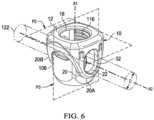
- converter member 10 can have a generally saddle-shaped, full-lobed configuration.
- Saddle-shaped, full-lobed converter member 10 can be a unitary member having two operative portions that can be distinguished by intersecting axially oriented openings.
- a first portion 12 can be defined as having a surface substantially parallel to a first portion plane P2, and which is the part of saddle-shaped, full-lobed converter member 10 that defines a first portion opening 18 that at least partially surrounds a first portion axis A1, which in operation is associated with a longitudinal axis of tulip head set screw 124 (not shown) and is perpendicular to first portion plane P2.
- a second portion 20 can include at least one, and can have one or more lobes (e.g., a first lobe 20A and a second lobe 20B), with each lobe extending downwardly in a spaced, substantially parallel relationship, from first portion 12 and having a surface substantially parallel to a second portion plane P3, and each having a shaped surface 22.
- the shaped surface 22 can have a closed perimeter defining an enclosed opening 32 through which spinal fixation rod 122 can be inserted and secured.
- Second portion plane P3 can be perpendicular to first portion plane P2 and second portion axis A2.
- tulip head set screw 124 can be secured through first portion opening 18 of first portion 12 of saddle-shaped, full-lobed converter member 10 to internal threads 116 of tulip head for securement, or additional securement, to join and/or secure the converter member 10 to tulip head 106.
- the tulip head set screw 124 can be effectively counter-sunk into the first portion 12 of converter member 10 and provide for secure joining of the converter member 10 to the tulip head 106.
- Tulip head set screw 124 can additionally supply securement forces against spinal fixation rod 124.
- the perimeter of opening 18 can also have internal threads that can work in conjunction with the internal threads 116 of tulip head 106.
- first portion 12 of saddle-shaped, full-lobed converter member 10 can cover and partially surround the top of tulip head 106.
- first portion axis A1 can be coaxial with the tulip head set screw 124 (not shown).
- Second portion 20 can be defined as the part of saddle shaped, full-lobed converter member 10 that defines at least one, and can be two, lobe openings 34, each lobe opening at least partially surrounding and defining a second portion axis A2, which in operation is associated with the longitudinal axis of spinal fixation rod 122.
- second portion axis A2 can be coaxial with the longitudinal axis of spinal fixation rod 122.
- First portion axis A1 can be perpendicular and co-planar with second portion axis A2.
- First portion 12 of saddle-shaped, full-lobed converter member 10 can seat on top of tulip head 106, having a portion that surrounds tulip head 106 to prevent splaying of tulip head 106 when forces from spinal fixation rod 122 are upward.
- Second portion 20 of saddle-shaped converter member 10 can include one or two downward-oriented partial or full lobes (shown as full first and second lobes 20A and/or 20B) that can be substantially parallel to a plane that can be perpendicular to axis A2.
Landscapes
- Health & Medical Sciences (AREA)
- Orthopedic Medicine & Surgery (AREA)
- Life Sciences & Earth Sciences (AREA)
- Surgery (AREA)
- Neurology (AREA)
- Heart & Thoracic Surgery (AREA)
- Engineering & Computer Science (AREA)
- Biomedical Technology (AREA)
- Nuclear Medicine, Radiotherapy & Molecular Imaging (AREA)
- Medical Informatics (AREA)
- Molecular Biology (AREA)
- Animal Behavior & Ethology (AREA)
- General Health & Medical Sciences (AREA)
- Public Health (AREA)
- Veterinary Medicine (AREA)
- Surgical Instruments (AREA)
Description
- Spinal fixation systems may be used to surgically fix, adjust, and/or align the spinal column. One type of spinal fixation system employs a spinal fixation rod for supporting the spine and fixing, adjusting, aligning, and/or fusing all or portions of the spinal column into a desired orientation. Attachment of the spinal fixation rod to the spinal column has been achieved using a variety of vertebral anchors (i.e., bone anchors). Vertebral anchors include screws, hooks, pins, and bolts used to engage the vertebrae and connect the spinal rod to vertebrae. Pedicle screws have been used successfully as vertebral anchors. Bone anchors (e.g., pedicle screws) and connectors in combination with spinal rods can align and correct deformities in the natural spinal alignment as well as repair traumatic injury.
- In general, a pedicle screw can have a head with a receiving opening into which a spinal rod can be secured. The open head of a pedicle screw of this type is often referred to as a "tulip head." An open style tulip-head pedicle screw permits a spinal fixation rod to be translated, i.e., "reduced" into the tulip head via the receiving opening after the pedicle screw has been screwed into the pedicle bone. Once reduced, a set screw can be screwed into threads internally disposed in the receiving opening, effectively closing the opening and fixing the spinal fixation rod into the pedicle screw.
- Pedicle screws can also be of the "closed head" style, in which the head is not open to receive a rod translated, or reduced, therein. Rather, the screw head has an opening, i.e., a through hole, through which a spinal fixation rod can be fed, and thereby fixed to the pedicle screw. It is believed that closed head style pedicle screws can withstand greater forces exerted by the spinal fixation rod on the pedicle screw. For example, it is believed that closed head style ORT 0026
WO/40504-0046 EP Appl. 20783943.2 102652079.DOCX June 23, 2023 - At times, a surgeon may wish to utilize a closed style pedicle screw where an open style tulip head has previously been set, i.e., screwed into a portion of the pedicle bone. It can be the case that during the process of spinal fixation it is discovered that an existing open style tulip head is not desirable, but removing it and replacing it with a closed style head can both add additional surgery time and cause additional trauma to the bone during the screw replacement process.
-
US 2007/055242 A1 is directed to a device for securing a spinal rod to a fixation device such as a pedicle screw or a lamina hook. The device disclosed herein includes a head portion configured to receive a spinal rod, a locking cap configured to engage the head portion and the spinal rod upon rotation of the locking cap relative to the head portion to secure the position of the head portion and the locking cap relative to the spinal rod, and a fastener portion extending from the head portion and configured to engage the spine. The fastener portion of the device can be in the form of a screw, hook or clamp, or any other configuration known in the art. - Accordingly, there remains an unmet need for an apparatus, system, and method to provide for improved bone anchors.
- The present invention relates to a unitary saddle-shaped pedicle screw tulip head converter, the converter comprising: a first portion and a second portion extending from the first portion, the first portion having a surface parallel to a first portion plane, and a first portion opening defining a first portion axis perpendicular to the first portion plane, wherein the first portion opening is, in operation, associated with the longitudinal axis of a tulip head set screw, the second portion comprising at least one lobe extending downwardly from the first portion, the at least one lobe having a surface parallel to a second portion plane, the second portion plane being perpendicular to the first portion plane, the at least one lobe having a shaped surface for contacting and additional securement of a spinal fixation rod which is reducible into the pedicle screw tulip head, the spinal fixation rod defining a second portion axis, the second portion axis being perpendicular to and coplanar with the first portion axis, wherein the shaped surface of the at least one lobe comprises a closed perimeter defining an enclosed opening through which the spinal fixation rod can be inserted and secured.
- Preferred embodiments are set forth in the dependent claims.
- The present disclosure will be more readily understood from a detailed description of some example embodiments taken in conjunction with the following figures:
-
FIG. 1 depicts a side elevation view of a representative open style tulip head pedicle screw. -
FIG. 2 depicts a partial cross-sectional view of a representative open style tulip head of a pedicle screw. -
FIG. 3 depicts a schematic representation of one example of an open style tulip head pedicle screw installed in a bone. -
FIG. 4 depicts a perspective view of one example of a closed style pedicle screw of the present disclosure. -
FIG. 5 depicts a partial perspective view of one example of an open style tulip head pedicle screw of the present disclosure. -
FIG. 6 depicts a perspective view of one example of a converter member of the present disclosure. - Various non-limiting embodiments of the present disclosure will now be described to provide an overall understanding of the principles of the structure, function, and use of the apparatuses, systems, methods (these methods not being claimed), and processes disclosed herein. One or more examples of these non-limiting embodiments are illustrated in the accompanying drawings. Those of ordinary skill in the art will understand that systems and methods specifically described herein and illustrated in
- The examples discussed herein are examples only and are provided to assist in the explanation of the apparatuses, devices, systems and methods described herein. None of the features or components shown in the drawings or discussed below should be taken as mandatory for any specific implementation of any of these the apparatuses, devices, systems or methods unless specifically designated as mandatory. For ease of reading and clarity, certain components, modules, or methods may be described solely in connection with a specific figure. Any failure to specifically describe a combination or sub-combination of components should not be understood as an indication that any combination or sub-combination is not possible. Also, for any methods described, regardless of whether the method is described in conjunction with a flow diagram, it should be understood that unless otherwise specified or required by context, any explicit or implicit ordering of steps performed in the execution of a method does not imply that those steps must be performed in the order presented but instead may be performed in a different order or in parallel.
- Described herein are example embodiments of bone anchors (e.g., anchors, screws, etc.) useful for orthopedic procedures such as, for example, spinal fixation. In the illustrated embodiments a pedicle screw is disclosed to teach the features and benefits of a bone screw, but the disclosure is not to be limited only to pedicle screws, nor are the bone anchor head converters limited to engaging and/or working with only pedicle screws. Such extenders may configured to engage and/or work with any type of bone anchor, both mono-axial and/or polyaxial. As used herein, an "open style" bone anchor is a bone anchor having a "tulip head" in which a spinal fixation rod can be translated into, i.e., reduced into the head through a receiving opening at, for example, the top of the tulip head. One example of an open style bone anchor (or open style pedicle screw) is a pedicle screw having a "tulip head" in which a spinal fixation rod can be translated into, i.e., reduced into the head through a receiving opening at, for example, the top of the tulip head and into
channel 107, as described with respect toFIGS. 1-3 herein. As used herein, a "closed style" bone anchor is a bone anchor screw having an opening through which a spinal fixation rod can be fed through a receiving opening at, for example, a side of the tulip head. One example of a "closed style" bone anchor (or closed style pedicle screw) is a pedicle screw having an opening through which a spinal fixation rod can be fed through a receiving opening at, for example, a side of the tulip head, as described with respect toFIG. 4 herein. - Referring to
FIG. 1 , a representative openstyle pedicle screw 100 is shown. Openstyle pedicle screw 100 can be any of known pedicle screws of the type often referred to as having "tulip heads." For the purposes of the present disclosure, the open style pedicle screw is described as including ascrew shank 102, aneck 104, ahead 106, which is often referred to as atulip head 106. Thetulip head 106 can include first andsecond tulip arms 112 opposed from each other. First and second tulip arms can form achannel 107. First andsecond tulip arms 112 can extend from a curved lower surface (e.g., rod seat 108) defining the substantially U-shapedinterior channel 107. Thechannel 107 can be constructed to receive a spinal fixation rod (e.g., 122) and can include a channel axis. The channel axis can correspond to, and be coincident with, a longitudinal axis of a spinal fixation rod when it is reduced into thechannel 107. Therod 122 can be reduced into thechannel 107 until it rests on a portion of the open channel surface, e.g., therod seat 108. The shank can have an inner diameter and an outer diameter, the inner diameter and outer diameter each being determined by the size of the screw and the depth ofthreads 110 onshank 102. The thread depth, pitch, and other dimensional features can be predetermined based on the requirements of the pedicle screw, as is known in the art. That is, the proportions of the bone screw depicted are for illustrative purposes only and variations in the length of the shank, diameter of the screw, thread pitch, thread length, number of thread leads, shank induced compression and the like may be varied. - Other components and features of an open style pedicle screw can be included that aid in insertion and use of the pedicle screw, including spinal fixation rod reduction. For example, as depicted in the partial cross-sectional view of
tulip head 106 inFIG. 2 ,tulip head 106 can include features for compatible operation with driving tool (not shown) and a rod reduction device (not shown). As a specific example, a rod reduction device, as is known in the art, may be used to engage withtulip head 106 to urge, or reduce, a spinal fixation rod into thechannel 107 and toward therod seat 108, manipulate one or more vertebrae, and/or insert a set screw for temporary or stationary fixation of the spinal rod into the pediclescrew tulip head 106. For this reason,tulip head 106 can have various features, such asgrasping tabs 112 and/orpockets 114, for connectivity and operation of the driving tool and/or rod reducing tool, andinternal threads 116 for receiving a set screw. - Referring now to
FIG. 3 , there is shown an openstyle pedicle screw 100 screwed into abone 118, the surface of which is representatively depicted by thedashed line 120.Bone 118 can be a pedicle, andpedicle screw 100 can be driven into the pedicle until theneck 104 is adjacent thebone 118. In an embodiment, the pedicle can be undertapped for the appropriate screw size. After the pedicle is undertapped a flexible feeler probe may be used to verify presence of threads in the tapped hole. To measure the length of the hole, a feeler probe is advanced to the floor of the hole and a hemostat is clamped to the feeler probe at the point where it exits the pedicle. The appropriate screw diameter and length may subsequently be selected based on both preoperative measurement and intraoperative observation. The same technique can be repeated for any remaining pedicles that need to be instrumented. - A rod reduction tool can be applied over the
tulip head 106 of the screw. In an embodiment, fingers of the rod reduction device can engage thepockets 114 of the pediclescrew tulip head 106. Therod 122 can then be reduced by the rod reduction device to set inrod seat 108. A set screw driver can then be used to introduce aset screw 124. The set screw can be passed through the rod reduction device and rotated until it bottoms out, securingrod 122 into thetulip head 106. - As depicted in
FIG. 3 , oncerod 122 is reduced intotulip head 106 and setscrew 124 is set, the distance D1 frombone surface 120 and theaxial center 126 ofrod 122 is immovably fixed. However, due to spinal curvature or other forces imposed on thespinal fixation rod 122, thespinal fixation rod 122 can have exerted thereon forces against the set screw 124 (upwardly as depicted inFIG. 3 ). If the forces exerted againstset screw 124 become too great the set screw can fail, thereby allowing thespinal fixation rod 122 to move out of place. Another mode of failure can be splaying of the tulip head, which also results in loss threaded connection of theset screw 124, and loss of placement of thespinal fixation rod 122 - Referring to
FIG. 4 there is shown a representative embodiment of a closedstyle pedicle screw 200. For the purposes of the present disclosure, the closed style pedicle screw is described as including ascrew shank 202, aneck 204, and ahead 206. Thehead 206, rather than being an open tulip style head, is a closed head that includes a through hole opening 208 disposed therethrough. This through hole opening 208 can allow a spinal fixation rod to be fed into, fed through, and ultimately, secured to thepedicle screw 200. As discussed above, for closed style pedicle screws, the shank can have an inner diameter and an outer diameter, the inner diameter and outer diameter each being determined by the size of the screw and the depth ofthreads 210 onshank 202. The thread depth, pitch, and other dimensional features can be predetermined based on the requirements of the pedicle screw, as is known in the art. That is, the proportions of the bone screw depicted are for illustrative purposes only and variations in the length of the shank, diameter of the screw, thread pitch, thread length, number of thread leads, shank induced compression and the like may be varied without departing from the scope of the disclosure. As can be understood, although more difficult to work with, the closed style pedicle screw head can completely surround thespinal fixation rod 124, thereby alleviating one or more of the problems of set screw failure discussed above with respect to open style pedicle screw heads. - Referring to
FIG. 5 , there is shown an example embodiment of an open stylepedicle tulip head 106 showing representative features that can be used for connectivity and operation, and can be intended on such a screw to facilitate the driving tool and/or rod reducing tool. For the present disclosure such features, and any other features of their kind, can be utilized to facilitate conversion of an open style pedicle screw to a closed style pedicle screw. As shown inFIG. 5 , for example, an open stylepedicle tulip head 106 can haveinternal threads 116 and indented portions, referred to herein aspockets 114 on variouslateral surfaces 130 of the open stylepedicle tulip head 106. As will be more fully understood in light of the description below, pockets 114 can be utilized for secondary purposes, i.e., to facilitate the conversion of an open style pedicle screw into a pedicle screw having a closed head. Other types of open style bone anchors, e.g., open style bone hooks, may include one or more similar and/or the same features as described above with reference to thepedicle screw 100. - In illustrated embodiments of the present disclosure a converter member is disclosed that can be joined to an open style tulip head of a bone anchor. The term "joined" or its derivatives means operatively mated in a connecting manner such that an open style tulip head is converted to operate as a closed style pedicle screw head. Joining can be by adhesive, press fit, snap fit, threaded screw fit, and the like. In an embodiment, converter member can be snap fit by having extensions (not shown) that snap into pockets to securely hold converter member to open style tulip head. In an embodiment, converter member has dimensions designed for a particular open style tulip head such that portions can elastically extend over the top of the tulip head and, when pushed sufficiently down, snap into one or more pockets.
- In an embodiment, a converter member can be an integral unit, except for embodiments in which a second portion set screw is utilized, as described below. That is, converter member can be a single piece unit that can be, for example, made of molded polymer. In an embodiment converter member can be injection molded of a polymer material suitable for use in a human body. In general, the converter member can be smooth sided, having smooth contours. In the illustrated embodiments, terms such as "vertical," "upper," "lower" "upwardly," and "downwardly" are used in relation to the converter member in the orientation shown in the FIGS, and corresponding to the orientation generally experienced and understood in the use of pedicle screws and related instrumentation. Likewise, for descriptive purposes various planes are referred in describing relative orientations of features and surfaces. However, the term "plane" is not intended to imply any flatness, smoothness, or other planar characteristics to the features and surfaces so described.
- Referring now to
FIG. 6 , in anembodiment converter member 10 can have a generally saddle-shaped, full-lobed configuration. Saddle-shaped, full-lobed converter member 10 can be a unitary member having two operative portions that can be distinguished by intersecting axially oriented openings. Afirst portion 12 can be defined as having a surface substantially parallel to a first portion plane P2, and which is the part of saddle-shaped, full-lobed converter member 10 that defines a first portion opening 18 that at least partially surrounds a first portion axis A1, which in operation is associated with a longitudinal axis of tulip head set screw 124 (not shown) and is perpendicular to first portion plane P2. Asecond portion 20 can include at least one, and can have one or more lobes (e.g., afirst lobe 20A and asecond lobe 20B), with each lobe extending downwardly in a spaced, substantially parallel relationship, fromfirst portion 12 and having a surface substantially parallel to a second portion plane P3, and each having a shapedsurface 22. In an embodiment, the shapedsurface 22 can have a closed perimeter defining anenclosed opening 32 through whichspinal fixation rod 122 can be inserted and secured. Second portion plane P3 can be perpendicular to first portion plane P2 and second portion axis A2. - In an embodiment, tulip head set
screw 124 can be secured through first portion opening 18 offirst portion 12 of saddle-shaped, full-lobed converter member 10 tointernal threads 116 of tulip head for securement, or additional securement, to join and/or secure theconverter member 10 totulip head 106. The tulip head setscrew 124 can be effectively counter-sunk into thefirst portion 12 ofconverter member 10 and provide for secure joining of theconverter member 10 to thetulip head 106. Tulip head setscrew 124 can additionally supply securement forces againstspinal fixation rod 124. In an embodiment, the perimeter of opening 18 can also have internal threads that can work in conjunction with theinternal threads 116 oftulip head 106. - In operation,
first portion 12 of saddle-shaped, full-lobed converter member 10 can cover and partially surround the top oftulip head 106. When installed on atulip head 106, as shown inFIG. 6 , first portion axis A1 can be coaxial with the tulip head set screw 124 (not shown).Second portion 20 can be defined as the part of saddle shaped, full-lobed converter member 10 that defines at least one, and can be two, lobe openings 34, each lobe opening at least partially surrounding and defining a second portion axis A2, which in operation is associated with the longitudinal axis ofspinal fixation rod 122. When in use, second portion axis A2 can be coaxial with the longitudinal axis ofspinal fixation rod 122. First portion axis A1 can be perpendicular and co-planar with second portion axis A2. -
First portion 12 of saddle-shaped, full-lobed converter member 10 can seat on top oftulip head 106, having a portion that surroundstulip head 106 to prevent splaying oftulip head 106 when forces fromspinal fixation rod 122 are upward.Second portion 20 of saddle-shapedconverter member 10 can include one or two downward-oriented partial or full lobes (shown as full first andsecond lobes 20A and/or 20B) that can be substantially parallel to a plane that can be perpendicular to axis A2. - The foregoing description of embodiments and examples has been presented for purposes of illustration and description. The scope of the invention is defined by the claims appended hereto.
Claims (5)
- A unitary saddle-shaped pedicle screw tulip head converter (10), the converter (10) comprising:
a first portion (12) and a second portion (20) extending from the first portion (12),the first portion (12) having a surface parallel to a first portion plane (P2), and a first portion opening (18) defining a first portion axis (A1) perpendicular to the first portion plane (P2),wherein the first portion opening (18) is, in operation, associated with the longitudinal axis of a tulip head set screw (124),the second portion (20) comprising at least one lobe (20A) extending downwardly from the first portion (12), the at least one lobe (20A) having a surface parallel to a second portion plane (P3), the second portion plane (P3) being perpendicular to the first portion plane (P2), the at least one lobe (20A) having a shaped surface (22) for contacting and additional securement of a spinal fixation rod (122) which is reducible into the pedicle screw tulip head (106), the spinal fixation rod (122) defining a second portion axis (A2), the second portion axis (A2) being perpendicular to and coplanar with the first portion axis (A1), characterized in that the shaped surface (22) of the at least one lobe (20A) comprises a closed perimeter defining an enclosed opening (32) through which the spinal fixation rod (122) can be inserted and secured. - The pedicle screw tulip head converter (10) of claim 1, wherein the at least one lobe (20A) of the second portion (20) comprises a first lobe (20A) and a second lobe (20B).
- The pedicle screw tulip head converter (10) of claim 2, wherein the first and second lobes (20A, 20B) being in a spaced, parallel relationship.
- The pedicle screw tulip head converter (10) of claim 1, wherein the second portion (20) further comprises a second lobe (20B), wherein the second lobe (20B) comprises a closed perimeter defining an enclosed opening.
- The pedicle screw tulip head converter (10) of claim 1, wherein the first portion opening (18) comprises internal threads.
Applications Claiming Priority (2)
| Application Number | Priority Date | Filing Date | Title |
|---|---|---|---|
| US201962828837P | 2019-04-03 | 2019-04-03 | |
| PCT/US2020/026477 WO2020206182A1 (en) | 2019-04-03 | 2020-04-02 | Bone anchor head converter |
Publications (3)
| Publication Number | Publication Date |
|---|---|
| EP3946104A1 EP3946104A1 (en) | 2022-02-09 |
| EP3946104A4 EP3946104A4 (en) | 2022-12-28 |
| EP3946104B1 true EP3946104B1 (en) | 2025-06-04 |
Family
ID=72666466
Family Applications (1)
| Application Number | Title | Priority Date | Filing Date |
|---|---|---|---|
| EP20783943.2A Active EP3946104B1 (en) | 2019-04-03 | 2020-04-02 | Bone anchor head converter |
Country Status (7)
| Country | Link |
|---|---|
| US (1) | US12558130B2 (en) |
| EP (1) | EP3946104B1 (en) |
| JP (2) | JP7607937B2 (en) |
| AU (1) | AU2020256229B2 (en) |
| BR (1) | BR112021018741A2 (en) |
| CA (1) | CA3135613A1 (en) |
| WO (1) | WO2020206182A1 (en) |
Families Citing this family (1)
| Publication number | Priority date | Publication date | Assignee | Title |
|---|---|---|---|---|
| EP3946104B1 (en) | 2019-04-03 | 2025-06-04 | OrthoPediatrics Corp. | Bone anchor head converter |
Family Cites Families (19)
| Publication number | Priority date | Publication date | Assignee | Title |
|---|---|---|---|---|
| US5667508A (en) * | 1996-05-01 | 1997-09-16 | Fastenetix, Llc | Unitary locking cap for use with a pedicle screw |
| FR2775582B1 (en) * | 1998-03-04 | 2000-10-13 | Dimso Sa | RACHIDIAN OSTEOSYNTHESIS BODY FOR FIXING A LIGAMENT |
| DE10005385A1 (en) * | 2000-02-07 | 2001-08-09 | Ulrich Gmbh & Co Kg | Pedicle screw |
| EP1372539B1 (en) * | 2001-03-06 | 2009-10-14 | Sung-Kon Kim | Screw for fixing spine |
| EP1446061B1 (en) * | 2001-11-22 | 2006-03-01 | SYNTHES AG Chur | Device for joining a longitudinal support with a bone fixation means |
| WO2006047707A2 (en) * | 2004-10-25 | 2006-05-04 | Alphaspine, Inc. | Pedicle screw systems and methods of assembling/installing the same |
| US7766946B2 (en) * | 2005-07-27 | 2010-08-03 | Frank Emile Bailly | Device for securing spinal rods |
| US7695497B2 (en) * | 2005-09-12 | 2010-04-13 | Seaspine, Inc. | Implant system for osteosynthesis |
| EP1795134B1 (en) | 2005-11-17 | 2008-08-06 | BIEDERMANN MOTECH GmbH | Polyaxial screw for flexible rod |
| CN101500500B (en) * | 2006-06-05 | 2011-05-11 | 特雷伯有限公司 | spine fixation device |
| US20100274295A1 (en) | 2009-04-24 | 2010-10-28 | Warsaw Orthopedic, Inc. | Medical implant configured to deliver a therapeutic substance |
| US20120130436A1 (en) * | 2010-11-23 | 2012-05-24 | Aesculap Implant Systems, Llc | Head to head connector for bone fixation assemblies |
| US9186184B2 (en) * | 2011-02-14 | 2015-11-17 | Pioneer Surgical Technology, Inc. | Spinal fixation system and method |
| EP2505155A1 (en) * | 2011-03-31 | 2012-10-03 | Spinelab AG | Spinal implant for stabilising and reinforcing spinal bodies of a spine |
| EP2591738A1 (en) * | 2011-11-14 | 2013-05-15 | Biedermann Technologies GmbH & Co. KG | Polyaxial bone anchoring device |
| US10786285B2 (en) * | 2016-06-06 | 2020-09-29 | Stryker European Holdings I, Llc | Paraxial revision rod-to-rod connector |
| US10485596B2 (en) * | 2016-12-06 | 2019-11-26 | Medos International Sàrl | Longitudinally-adjustable bone anchors and related methods |
| US20180228516A1 (en) * | 2017-02-14 | 2018-08-16 | Warsaw Orthopedic, Inc. | Spinal implant system and method |
| EP3946104B1 (en) | 2019-04-03 | 2025-06-04 | OrthoPediatrics Corp. | Bone anchor head converter |
-
2020
- 2020-04-02 EP EP20783943.2A patent/EP3946104B1/en active Active
- 2020-04-02 BR BR112021018741A patent/BR112021018741A2/en active Search and Examination
- 2020-04-02 CA CA3135613A patent/CA3135613A1/en active Pending
- 2020-04-02 US US17/600,528 patent/US12558130B2/en active Active
- 2020-04-02 JP JP2021556698A patent/JP7607937B2/en active Active
- 2020-04-02 WO PCT/US2020/026477 patent/WO2020206182A1/en not_active Ceased
- 2020-04-02 AU AU2020256229A patent/AU2020256229B2/en active Active
-
2024
- 2024-12-11 JP JP2024216067A patent/JP2025029208A/en active Pending
Also Published As
| Publication number | Publication date |
|---|---|
| BR112021018741A2 (en) | 2022-03-03 |
| EP3946104A1 (en) | 2022-02-09 |
| WO2020206182A1 (en) | 2020-10-08 |
| AU2020256229A1 (en) | 2021-10-28 |
| JP2025029208A (en) | 2025-03-05 |
| US20220192717A1 (en) | 2022-06-23 |
| JP2022526887A (en) | 2022-05-27 |
| US12558130B2 (en) | 2026-02-24 |
| CA3135613A1 (en) | 2020-10-08 |
| JP7607937B2 (en) | 2025-01-06 |
| EP3946104A4 (en) | 2022-12-28 |
| AU2020256229B2 (en) | 2026-04-16 |
Similar Documents
| Publication | Publication Date | Title |
|---|---|---|
| US7371239B2 (en) | Spinal rod insertion instrument | |
| EP2455031B1 (en) | Head to head connector for bone fixation assemblies | |
| US12201328B2 (en) | Bone anchor head extender | |
| US20090062864A1 (en) | Offset connection bone anchor assembly | |
| US20250176977A1 (en) | Mis cross-connector | |
| US20060084990A1 (en) | Dual anchor spinal implant apparatus | |
| EP1862136A2 (en) | Orthopaedic rod/plate locking mechanisms and surgical methods | |
| USRE50489E1 (en) | Pedicle screws with integrated anchor for retaining artificial ligament tape used for posterior ligament reconstruction | |
| JP2019523076A (en) | Restrained implants and systems for orthopedics | |
| US8551146B2 (en) | Spinal fixation system | |
| EP3062717B1 (en) | Percutaneous transverse connector system | |
| JP2025029208A (en) | Bone anchor head converter | |
| US11974785B2 (en) | Band clamp implants | |
| US20250380971A1 (en) | Offset rod connector | |
| EP1901668A1 (en) | Dual anchor spinal implant apparatus | |
| BR112021011300B1 (en) | Pedicle Screw Tulip Head Extender |
Legal Events
| Date | Code | Title | Description |
|---|---|---|---|
| STAA | Information on the status of an ep patent application or granted ep patent |
Free format text: STATUS: THE INTERNATIONAL PUBLICATION HAS BEEN MADE |
|
| PUAI | Public reference made under article 153(3) epc to a published international application that has entered the european phase |
Free format text: ORIGINAL CODE: 0009012 |
|
| STAA | Information on the status of an ep patent application or granted ep patent |
Free format text: STATUS: REQUEST FOR EXAMINATION WAS MADE |
|
| 17P | Request for examination filed |
Effective date: 20210922 |
|
| AK | Designated contracting states |
Kind code of ref document: A1 Designated state(s): AL AT BE BG CH CY CZ DE DK EE ES FI FR GB GR HR HU IE IS IT LI LT LU LV MC MK MT NL NO PL PT RO RS SE SI SK SM TR |
|
| DAV | Request for validation of the european patent (deleted) | ||
| DAX | Request for extension of the european patent (deleted) | ||
| A4 | Supplementary search report drawn up and despatched |
Effective date: 20221124 |
|
| RIC1 | Information provided on ipc code assigned before grant |
Ipc: A61B 17/70 20060101AFI20221118BHEP |
|
| GRAP | Despatch of communication of intention to grant a patent |
Free format text: ORIGINAL CODE: EPIDOSNIGR1 |
|
| STAA | Information on the status of an ep patent application or granted ep patent |
Free format text: STATUS: GRANT OF PATENT IS INTENDED |
|
| INTG | Intention to grant announced |
Effective date: 20241030 |
|
| GRAS | Grant fee paid |
Free format text: ORIGINAL CODE: EPIDOSNIGR3 |
|
| P01 | Opt-out of the competence of the unified patent court (upc) registered |
Free format text: CASE NUMBER: APP_8069/2025 Effective date: 20250218 |
|
| GRAA | (expected) grant |
Free format text: ORIGINAL CODE: 0009210 |
|
| STAA | Information on the status of an ep patent application or granted ep patent |
Free format text: STATUS: THE PATENT HAS BEEN GRANTED |
|
| AK | Designated contracting states |
Kind code of ref document: B1 Designated state(s): AL AT BE BG CH CY CZ DE DK EE ES FI FR GB GR HR HU IE IS IT LI LT LU LV MC MK MT NL NO PL PT RO RS SE SI SK SM TR |
|
| REG | Reference to a national code |
Ref country code: GB Ref legal event code: FG4D |
|
| REG | Reference to a national code |
Ref country code: CH Ref legal event code: EP |
|
| REG | Reference to a national code |
Ref country code: DE Ref legal event code: R096 Ref document number: 602020052331 Country of ref document: DE |
|
| REG | Reference to a national code |
Ref country code: IE Ref legal event code: FG4D |
|
| REG | Reference to a national code |
Ref country code: NL Ref legal event code: MP Effective date: 20250604 |
|
| PG25 | Lapsed in a contracting state [announced via postgrant information from national office to epo] |
Ref country code: FI Free format text: LAPSE BECAUSE OF FAILURE TO SUBMIT A TRANSLATION OF THE DESCRIPTION OR TO PAY THE FEE WITHIN THE PRESCRIBED TIME-LIMIT Effective date: 20250604 Ref country code: ES Free format text: LAPSE BECAUSE OF FAILURE TO SUBMIT A TRANSLATION OF THE DESCRIPTION OR TO PAY THE FEE WITHIN THE PRESCRIBED TIME-LIMIT Effective date: 20250604 |
|
| REG | Reference to a national code |
Ref country code: LT Ref legal event code: MG9D |
|
| PG25 | Lapsed in a contracting state [announced via postgrant information from national office to epo] |
Ref country code: NO Free format text: LAPSE BECAUSE OF FAILURE TO SUBMIT A TRANSLATION OF THE DESCRIPTION OR TO PAY THE FEE WITHIN THE PRESCRIBED TIME-LIMIT Effective date: 20250904 Ref country code: GR Free format text: LAPSE BECAUSE OF FAILURE TO SUBMIT A TRANSLATION OF THE DESCRIPTION OR TO PAY THE FEE WITHIN THE PRESCRIBED TIME-LIMIT Effective date: 20250905 |
|
| PG25 | Lapsed in a contracting state [announced via postgrant information from national office to epo] |
Ref country code: PL Free format text: LAPSE BECAUSE OF FAILURE TO SUBMIT A TRANSLATION OF THE DESCRIPTION OR TO PAY THE FEE WITHIN THE PRESCRIBED TIME-LIMIT Effective date: 20250604 |
|
| PG25 | Lapsed in a contracting state [announced via postgrant information from national office to epo] |
Ref country code: BG Free format text: LAPSE BECAUSE OF FAILURE TO SUBMIT A TRANSLATION OF THE DESCRIPTION OR TO PAY THE FEE WITHIN THE PRESCRIBED TIME-LIMIT Effective date: 20250604 |
|
| PG25 | Lapsed in a contracting state [announced via postgrant information from national office to epo] |
Ref country code: HR Free format text: LAPSE BECAUSE OF FAILURE TO SUBMIT A TRANSLATION OF THE DESCRIPTION OR TO PAY THE FEE WITHIN THE PRESCRIBED TIME-LIMIT Effective date: 20250604 |
|
| PG25 | Lapsed in a contracting state [announced via postgrant information from national office to epo] |
Ref country code: RS Free format text: LAPSE BECAUSE OF FAILURE TO SUBMIT A TRANSLATION OF THE DESCRIPTION OR TO PAY THE FEE WITHIN THE PRESCRIBED TIME-LIMIT Effective date: 20250904 |
|
| PG25 | Lapsed in a contracting state [announced via postgrant information from national office to epo] |
Ref country code: LV Free format text: LAPSE BECAUSE OF FAILURE TO SUBMIT A TRANSLATION OF THE DESCRIPTION OR TO PAY THE FEE WITHIN THE PRESCRIBED TIME-LIMIT Effective date: 20250604 |
|
| PG25 | Lapsed in a contracting state [announced via postgrant information from national office to epo] |
Ref country code: NL Free format text: LAPSE BECAUSE OF FAILURE TO SUBMIT A TRANSLATION OF THE DESCRIPTION OR TO PAY THE FEE WITHIN THE PRESCRIBED TIME-LIMIT Effective date: 20250604 |
|
| PG25 | Lapsed in a contracting state [announced via postgrant information from national office to epo] |
Ref country code: PT Free format text: LAPSE BECAUSE OF FAILURE TO SUBMIT A TRANSLATION OF THE DESCRIPTION OR TO PAY THE FEE WITHIN THE PRESCRIBED TIME-LIMIT Effective date: 20251006 |
|
| REG | Reference to a national code |
Ref country code: AT Ref legal event code: MK05 Ref document number: 1799613 Country of ref document: AT Kind code of ref document: T Effective date: 20250604 |
|
| PG25 | Lapsed in a contracting state [announced via postgrant information from national office to epo] |
Ref country code: IS Free format text: LAPSE BECAUSE OF FAILURE TO SUBMIT A TRANSLATION OF THE DESCRIPTION OR TO PAY THE FEE WITHIN THE PRESCRIBED TIME-LIMIT Effective date: 20251004 |
|
| PG25 | Lapsed in a contracting state [announced via postgrant information from national office to epo] |
Ref country code: SM Free format text: LAPSE BECAUSE OF FAILURE TO SUBMIT A TRANSLATION OF THE DESCRIPTION OR TO PAY THE FEE WITHIN THE PRESCRIBED TIME-LIMIT Effective date: 20250604 Ref country code: AT Free format text: LAPSE BECAUSE OF FAILURE TO SUBMIT A TRANSLATION OF THE DESCRIPTION OR TO PAY THE FEE WITHIN THE PRESCRIBED TIME-LIMIT Effective date: 20250604 |
|
| PG25 | Lapsed in a contracting state [announced via postgrant information from national office to epo] |
Ref country code: CZ Free format text: LAPSE BECAUSE OF FAILURE TO SUBMIT A TRANSLATION OF THE DESCRIPTION OR TO PAY THE FEE WITHIN THE PRESCRIBED TIME-LIMIT Effective date: 20250604 |
|
| PG25 | Lapsed in a contracting state [announced via postgrant information from national office to epo] |
Ref country code: EE Free format text: LAPSE BECAUSE OF FAILURE TO SUBMIT A TRANSLATION OF THE DESCRIPTION OR TO PAY THE FEE WITHIN THE PRESCRIBED TIME-LIMIT Effective date: 20250604 |
|
| PG25 | Lapsed in a contracting state [announced via postgrant information from national office to epo] |
Ref country code: SK Free format text: LAPSE BECAUSE OF FAILURE TO SUBMIT A TRANSLATION OF THE DESCRIPTION OR TO PAY THE FEE WITHIN THE PRESCRIBED TIME-LIMIT Effective date: 20250604 Ref country code: RO Free format text: LAPSE BECAUSE OF FAILURE TO SUBMIT A TRANSLATION OF THE DESCRIPTION OR TO PAY THE FEE WITHIN THE PRESCRIBED TIME-LIMIT Effective date: 20250604 |
|
| PG25 | Lapsed in a contracting state [announced via postgrant information from national office to epo] |
Ref country code: IT Free format text: LAPSE BECAUSE OF FAILURE TO SUBMIT A TRANSLATION OF THE DESCRIPTION OR TO PAY THE FEE WITHIN THE PRESCRIBED TIME-LIMIT Effective date: 20250604 |
|
| REG | Reference to a national code |
Ref country code: DE Ref legal event code: R097 Ref document number: 602020052331 Country of ref document: DE |
|
| PLBE | No opposition filed within time limit |
Free format text: ORIGINAL CODE: 0009261 |
|
| STAA | Information on the status of an ep patent application or granted ep patent |
Free format text: STATUS: NO OPPOSITION FILED WITHIN TIME LIMIT |
|
| PG25 | Lapsed in a contracting state [announced via postgrant information from national office to epo] |
Ref country code: DK Free format text: LAPSE BECAUSE OF FAILURE TO SUBMIT A TRANSLATION OF THE DESCRIPTION OR TO PAY THE FEE WITHIN THE PRESCRIBED TIME-LIMIT Effective date: 20250604 |
|
| REG | Reference to a national code |
Ref country code: CH Ref legal event code: L10 Free format text: ST27 STATUS EVENT CODE: U-0-0-L10-L00 (AS PROVIDED BY THE NATIONAL OFFICE) Effective date: 20260416 |
|
| 26N | No opposition filed |
Effective date: 20260305 |