EP3945730A1 - Speaker assembly and display device comprising it - Google Patents
Speaker assembly and display device comprising it Download PDFInfo
- Publication number
- EP3945730A1 EP3945730A1 EP21153188.4A EP21153188A EP3945730A1 EP 3945730 A1 EP3945730 A1 EP 3945730A1 EP 21153188 A EP21153188 A EP 21153188A EP 3945730 A1 EP3945730 A1 EP 3945730A1
- Authority
- EP
- European Patent Office
- Prior art keywords
- bobbin
- disposed
- diaphragm
- magnets
- speaker
- Prior art date
- Legal status (The legal status is an assumption and is not a legal conclusion. Google has not performed a legal analysis and makes no representation as to the accuracy of the status listed.)
- Granted
Links
Images




Classifications
-
- H—ELECTRICITY
- H04—ELECTRIC COMMUNICATION TECHNIQUE
- H04R—LOUDSPEAKERS, MICROPHONES, GRAMOPHONE PICK-UPS OR LIKE ACOUSTIC ELECTROMECHANICAL TRANSDUCERS; ELECTRIC HEARING AIDS; PUBLIC ADDRESS SYSTEMS
- H04R9/00—Transducers of moving-coil, moving-strip, or moving-wire type
- H04R9/02—Details
- H04R9/04—Construction, mounting, or centering of coil
- H04R9/046—Construction
- H04R9/047—Construction in which the windings of the moving coil lay in the same plane
-
- H—ELECTRICITY
- H04—ELECTRIC COMMUNICATION TECHNIQUE
- H04R—LOUDSPEAKERS, MICROPHONES, GRAMOPHONE PICK-UPS OR LIKE ACOUSTIC ELECTROMECHANICAL TRANSDUCERS; ELECTRIC HEARING AIDS; PUBLIC ADDRESS SYSTEMS
- H04R1/00—Details of transducers, loudspeakers or microphones
- H04R1/02—Casings; Cabinets ; Supports therefor; Mountings therein
- H04R1/028—Casings; Cabinets ; Supports therefor; Mountings therein associated with devices performing functions other than acoustics, e.g. electric candles
-
- H—ELECTRICITY
- H04—ELECTRIC COMMUNICATION TECHNIQUE
- H04R—LOUDSPEAKERS, MICROPHONES, GRAMOPHONE PICK-UPS OR LIKE ACOUSTIC ELECTROMECHANICAL TRANSDUCERS; ELECTRIC HEARING AIDS; PUBLIC ADDRESS SYSTEMS
- H04R7/00—Diaphragms for electromechanical transducers; Cones
- H04R7/02—Diaphragms for electromechanical transducers; Cones characterised by the construction
- H04R7/04—Plane diaphragms
-
- H—ELECTRICITY
- H04—ELECTRIC COMMUNICATION TECHNIQUE
- H04R—LOUDSPEAKERS, MICROPHONES, GRAMOPHONE PICK-UPS OR LIKE ACOUSTIC ELECTROMECHANICAL TRANSDUCERS; ELECTRIC HEARING AIDS; PUBLIC ADDRESS SYSTEMS
- H04R7/00—Diaphragms for electromechanical transducers; Cones
- H04R7/16—Mounting or tensioning of diaphragms or cones
- H04R7/18—Mounting or tensioning of diaphragms or cones at the periphery
-
- H—ELECTRICITY
- H04—ELECTRIC COMMUNICATION TECHNIQUE
- H04R—LOUDSPEAKERS, MICROPHONES, GRAMOPHONE PICK-UPS OR LIKE ACOUSTIC ELECTROMECHANICAL TRANSDUCERS; ELECTRIC HEARING AIDS; PUBLIC ADDRESS SYSTEMS
- H04R9/00—Transducers of moving-coil, moving-strip, or moving-wire type
- H04R9/02—Details
- H04R9/025—Magnetic circuit
-
- H—ELECTRICITY
- H04—ELECTRIC COMMUNICATION TECHNIQUE
- H04R—LOUDSPEAKERS, MICROPHONES, GRAMOPHONE PICK-UPS OR LIKE ACOUSTIC ELECTROMECHANICAL TRANSDUCERS; ELECTRIC HEARING AIDS; PUBLIC ADDRESS SYSTEMS
- H04R9/00—Transducers of moving-coil, moving-strip, or moving-wire type
- H04R9/02—Details
- H04R9/04—Construction, mounting, or centering of coil
- H04R9/041—Centering
- H04R9/043—Inner suspension or damper, e.g. spider
-
- H—ELECTRICITY
- H04—ELECTRIC COMMUNICATION TECHNIQUE
- H04R—LOUDSPEAKERS, MICROPHONES, GRAMOPHONE PICK-UPS OR LIKE ACOUSTIC ELECTROMECHANICAL TRANSDUCERS; ELECTRIC HEARING AIDS; PUBLIC ADDRESS SYSTEMS
- H04R9/00—Transducers of moving-coil, moving-strip, or moving-wire type
- H04R9/06—Loudspeakers
-
- H—ELECTRICITY
- H04—ELECTRIC COMMUNICATION TECHNIQUE
- H04R—LOUDSPEAKERS, MICROPHONES, GRAMOPHONE PICK-UPS OR LIKE ACOUSTIC ELECTROMECHANICAL TRANSDUCERS; ELECTRIC HEARING AIDS; PUBLIC ADDRESS SYSTEMS
- H04R2400/00—Loudspeakers
- H04R2400/11—Aspects regarding the frame of loudspeaker transducers
-
- H—ELECTRICITY
- H04—ELECTRIC COMMUNICATION TECHNIQUE
- H04R—LOUDSPEAKERS, MICROPHONES, GRAMOPHONE PICK-UPS OR LIKE ACOUSTIC ELECTROMECHANICAL TRANSDUCERS; ELECTRIC HEARING AIDS; PUBLIC ADDRESS SYSTEMS
- H04R2499/00—Aspects covered by H04R or H04S not otherwise provided for in their subgroups
- H04R2499/10—General applications
- H04R2499/15—Transducers incorporated in visual displaying devices, e.g. televisions, computer displays, laptops
-
- H—ELECTRICITY
- H10—SEMICONDUCTOR DEVICES; ELECTRIC SOLID-STATE DEVICES NOT OTHERWISE PROVIDED FOR
- H10K—ORGANIC ELECTRIC SOLID-STATE DEVICES
- H10K50/00—Organic light-emitting devices
- H10K50/80—Constructional details
- H10K50/84—Passivation; Containers; Encapsulations
Definitions
- the present disclosure relates to a speaker assembly, and a display device including the same.
- LCD Liquid Crystal Display
- PDP Plasma Display Panel
- ELD Electro luminescent Display
- VFD Vacuum Fluorescent Display
- OLED Organic Light Emitting Diode
- the OLED display devices have effects in that in comparison with the LCD devices, the OLED display devices are excellent in brightness and viewing angle characteristics and require no backlight unit, such that the OLED display devices can be realized as ultra-thin displays.
- the above and other objects can be accomplished by providing a speaker assembly and a display device including the same, the speaker assembly including: a pair of magnets facing each other; a bobbin disposed between the pair of magnets and formed in a shape of a plate that extends long; a coil formed on at least one surface of the bobbin; a diaphragm fixed to one side of the bobbin, and extending in a direction intersecting a longitudinal direction of the bobbin; a frame disposed between the pair of magnets and the diaphragm; and a speaker edge disposed between the frame and the diaphragm, having one end fixed to the frame and the other end fixed to the diaphragm, and being convexly curved toward the bobbin.
- FIGS. 1 to 9 are diagrams illustrating examples of a speaker assembly, and a display device including the same, according to embodiments of the present disclosure.
- module and “part” for elements used in the following description are given simply in view of the ease of the description, and do not carry any important meaning or role. Therefore, the “module” and the “part” may be used interchangeably. Descriptions of some well-known technologies that possibly obscure the disclosure will be omitted, if necessary. Further, the accompanying drawings are used to help easily understand various technical features and it should be understood that the embodiments presented herein are not limited by the accompanying drawings. As such, the present disclosure should be construed to extend to any alterations, equivalents and substitutes in addition to those which are particularly set out in the accompanying drawings.
- OLED Organic Light Emitting Diode
- a display device 100 may include a first long side LS1; a second long side LS2 facing the first long side LS1; a first short side SS1 adjacent to the first long side LS1 and the second long side LS2; and a second short side SS2 facing the first short side SS1.
- an area of the first short side SS1 may be referred to as a first side area
- an area of the second short side SS2 may be referred to as a second side area facing the first side area.
- an area of the first long side LS1 may be referred to as a third side area being adjacent to the first side area and the second side area, and being disposed between the first side area and the second side area; and an area of the second long side LS2 may be referred to as a fourth side area being adjacent to the first side area and the second side area, being disposed between the first side area and the second side area, and facing the third side area.
- FIG. 1 illustrates an example in which the length of the first and second long sides LS1 and LS2 is greater than the length of the first and second short sides SS1 and SS2, but the length of the first and second long sides LS1 and LS2 may be approximately equal to the length of the first and second short sides SS1 and SS2.
- a first direction DR1 is a direction parallel to the first and second long sides LS1 and LS2 of a display panel 110
- a second direction DR2 is a direction parallel to the first and second short sides SS1 and SS2 of the display panel 110
- a third direction DR3 may be a direction perpendicular to the first direction DR1 and/or the second direction DR2.
- a side or a surface, on which the display device 100 displays an image may be referred to as a front side or a front surface.
- a side or a surface, at which the image may not be viewed may be referred to as a back side or a back surface.
- the first long side LS1 may be referred to as an upper side or an upper surface
- the second long side LS2 may be referred to as a lower side or a lower surface.
- the first short side SS1 may be referred to as a right side or a right surface
- the second short side SS2 may be referred to as a left side or a left surface.
- the first long side LS1, the second long side LS2, the first short side SS1, and the second short side SS2 may be referred to as edges of the display device 100. Further, positions where the first long side LS1, the second long side LS2, the first short side SS1, and the second short side SS2 meet each other may be referred to as corners.
- a position where the first long side LS1 and the first short side SS1 meet each other may be referred to as a first corner C1; a position where the first long side LS1 and the second short side SS2 meet each other may be referred to as a second corner C2; a position where the second short side SS2 and the second long side LS2 meet each other may be referred to as a third corner C3; and a position where the second long side LS2 and the first short side SS1 meet each other may be referred to as a fourth corner C4.
- a direction from the first short side SS1 to the second short side SS2 or a direction from the second short side SS2 to the first short side SS1 may be referred to as a left-right direction LR or a horizontal direction DR1.
- a direction from the first long side LS1 to the second long side LS2 or a direction from the second long side LS2 to the first long side LS1 may be referred to as an up-down direction UD or a vertical direction DR2.
- a direction from the front surface to the back surface or a direction from the back surface to the front surface may be referred to as a front-rear direction DR3 or a thickness direction.
- the front-rear direction DR3 may be a direction perpendicular to the left-right direction DR1 and/or the vertical direction DR2.
- the display device 100 may include the display panel 110, a main frame 120, and a speaker assembly 10.
- the display pane 110 may be provided on the front surface of the display device 100 and may display images.
- the main frame 120 may be disposed at a rear portion of the display panel 110.
- the main frame 120 may be connected to the display panel 110.
- the speaker assembly 10 may be disposed adjacent to a lower end of the main frame 120 to be installed at the main frame 120.
- the speaker assembly 10 may direct sound downwardly of the display device 100.
- the plate 20 may be formed in the shape of a flat plate that extends long.
- the plate 20 may be metal.
- the plate 20 may be a synthetic resin.
- the plate 20 may include a first plate 21 and a second plate 22.
- the first plate 21 may be parallel to the second plate 22 and may be spaced apart from the second plate 22.
- the plate 20 may be referred to as a rear plate 20.
- An elastic member 30 may support the plate 20.
- the elastic member 30 may be connected or fixed to a lower part of the plate 20.
- the elastic member 30 may be referred to as a damper 30.
- the elastic member 30 may include a center plate 31, bridges 32, 33, and 34, and circles 35, 36, and 37.
- the elastic member 30 may be metal.
- the elastic member 30 may be a synthetic resin.
- the center plate 31 may extend long in a longitudinal direction of the plate 20 and may be disposed between the first plate 21 and the second plate 22.
- the center plate 31 may be spaced apart from the first plate 21 and the second plate 22 at a position below the first plate 21 and the second plate 22.
- the bridges 32, 33, and 34 may be disposed in a direction intersecting a longitudinal direction of the center plate 31, and may extend across the center plate 31.
- the circles 35, 36, and 37 facing each other may be connected or fixed to both ends of the bridges 32, 33, and 34.
- the circles 35, 36, and 37 may have an elliptical shape.
- the circles 35, 36, and 37 may have elasticity. Upper surfaces of the circles 35, 36, and 37 may come into contact with the plate 20.
- the first bridge 32 may be disposed adjacent to one end of the center plate 31.
- a first circle 35a may be disposed on one end of the first bridge 32, and a second circle 35b may be disposed on the other end of the first bridge 32.
- the third bridge 34 may be disposed adjacent to the other end of the center plate 31.
- a fifth circle 37a may be disposed on one end of the third bridge 34, and a sixth circle 37b may be disposed on the other end of the third bridge 34.
- the second bridge 33 may be disposed between the first bridge 32 and the third bridge 34.
- the third circle 36a may be disposed on one end of the second bridge 36b, and the fourth circle 36b may be disposed on the other end of the second bridge 33.
- the circles 35, 36, and 37 may be connected or fixed to the bridges 32, 33, and 34.
- the first circle 35a may face the second circle 35b with respect to the center plate 31
- the third circle 36a may face the fourth circle 36b with respect to the center plate 31
- the fifth circle 37a may face the sixth circle 37b with respect to the center plate 31.
- a range of motion of the damper 30 may be increased or maximized relative to the size of the speaker assembly 10.
- the range of motion of the damper 30 may correlate to a reproduction band of the speaker assembly 10, such that a sound reproduction band of the speaker assembly 10 may be improved.
- sound pressure of the speaker assembly 10 may also be improved.
- magnets 40 may be disposed on the rear plate 20.
- the magnets 40 may have a square column shape that extends long.
- a first magnet 41 may be connected or fixed to an upper portion of the first rear plate 21, and a second magnet 42 may be connected or fixed to an upper portion of the second rear plate 22.
- the first magnet 41 may face the second magnet 42 with respect to the center plate 31.
- a plate 50 may extend long.
- the plate 50 may be connected or fixed to an upper portion of the magnets 40.
- the plate 50 may be referred to as a front plate 50.
- a first front plate 51 may be disposed on the first magnet 41, and the second front plate 52 may be disposed on the second magnet 42.
- the first front plate 51 may face the first rear plate 21 with respect to the first magnet 41.
- the second front plate 52 may face the second rear plate 22 with respect to the second magnet 42.
- a bobbin 81 may be formed in the shape of a flat plate that extends long.
- the bobbin 81 may be a printed circuit board (PCB).
- a voice coil 82 may be wound around the bobbin 81.
- the voice coil 82 may be wound around the bobbin 81 to form a closed-loop.
- the voice coil 82 may be printed on the bobbin 81.
- a vertical width Bw of the voice coil 82 may be greater than a vertical width Mw of the magnets 40.
- the bobbin 81 may be disposed between the first magnet 41 and the second magnet 42. When a current flows through the voice coil 82, the bobbin 81 may move in a vertical direction.
- a lower end of the bobbin 81 may be connected or fixed to the center plate 31.
- a frame 60 may be formed in the shape of a flat plate that extends long.
- the frame 60 may be connected or fixed to an upper portion of the front plate 50.
- a first frame 61 may be disposed on the first front plate 51, and a second frame 62 may be disposed on the second front plate 52.
- a speaker edge 70 may be connected or fixed to an upper portion of the frame 60.
- the speaker edge 70 may have elasticity.
- the speaker edge 70 may be formed in the shape of a cylinder that extends long.
- the speaker edge 70 may be formed in the shape of a cylinder cut in half.
- the speaker edge 70 may have a U-shaped cross-section.
- a first speaker edge 71 may be connected or fixed to an upper portion of the first frame 61, and a second speaker edge 72 may be connected or fixed to an upper portion of the second frame 62.
- the first speaker edge 71 may be convex toward the second speaker edge 72, and the second speaker edge 72 may be convex toward the first speaker edge 71.
- a diaphragm 90 may be formed in the shape of a plate that extends long.
- the diaphragm 90 may be fixed to an upper end of the bobbin 81.
- One long side 90LS1 of the diaphragm 90 may be connected or fixed to the first speaker edge 71, and the other long side 90LS2 of the diaphragm 90 may be connected or fixed to the second speaker edge 72. Accordingly, an area of the diaphragm 90 may be maximized relative to a thickness of the speaker assembly 10, and sound pressure may be improved.
- an outer surface of the first magnet 41 and an outer surface of the second magnet 42 may be exposed to the outside of the speaker assembly 10.
- a first distance D1 from the outer surface of the first magnet 41 to the outer surface of the second magnet 42 may be the thickness of the speaker assembly 10.
- Outer surfaces of the plates 20 and 60 may be aligned with respect to the outer surfaces of the magnets 40.
- the outer surfaces of the frames 60 may be aligned with respect to the outer surfaces of the magnets 40.
- a second distance D2 between an outer surface of the first rear plate 211 and an outer surface of the second rear plate 22 may be substantially equal to the first distance D1.
- a third distance D3 between an outer surface of the first front plate 51 and an outer surface of the second front plate 52 may be substantially equal to the first distance D1.
- a fourth distance D4 between an outer surface of the first front frame 61 and an outer surface of the second front frame 62 may be substantially equal to the first distance D1.
- a fifth distance D5 between an outer surface of the first rear frame 63 and an outer surface of the second rear frame 64 may be substantially equal to the first distance D1.
- a sixth distance D6 between one long side of the diaphragm 90 and the other long side of the diaphragm 90 may be substantially equal to the first distance D1.
- the sixth distance D6 may be substantially equal to the thickness of the speaker assembly 10. Accordingly, sound pressure generated by the diaphragm 90 may be maximized.
- the bobbin 81 may move from the front frames 61 and 62 toward the rear frames 63 and 64. As the bobbin 81 moves, the diaphragm 90 may move closer to the front frames 61 and 62, and the speaker edge 70 may be compressed. At the same time, the circles 37a and 37b of the damper 30 may be stretched in a longitudinal direction of the bobbin 81, such that a range of motion of the circles 37a and 37b of the damper 30 may be increased, and thus the amplitude of the diaphragm 90 may be increased.
- the bobbin 81 may move from the rear frames 63 and 64 toward the front frames 61 and 62. As the bobbin 81 moves, the diaphragm 90 may move further away from the front frames 61 and 62, and the speaker edge 70 may be stretched. At the same time, the circles 37a and 37b of the damper 30 may be compressed in a longitudinal direction of the bobbin 81, such that a range of motion of the circles 37a and 37b of the damper 30 may be increased, and thus the amplitude of the diaphragm 90 may be increased.
- the speaker assembly includes: a pair of magnets 40 facing each other; a bobbin 81 disposed between the pair of magnets 40 and formed in a shape of a plate that extends long; a coil 82 formed on at least one surface of the bobbin; a diaphragm 90 fixed to one side of the bobbin 81, and extending in a direction intersecting a longitudinal direction of the bobbin 81; a frame 60 disposed between the pair of magnets 40 and the diaphragm 90; and a speaker edge 70 disposed between the frame 60 and the diaphragm 90, having one end fixed to the frame 60 and the other end fixed to the diaphragm 90, and being convexly curved toward the bobbin 81.
- the speaker assembly may further include a damper 30 disposed to face the frame 60 with respect to the pair of magnets 40, fixed to the other side of the bobbin 81 which faces the one side of the bobbin 81, and providing elasticity to the bobbin 81.
- the damper may include: a center plate 31 extending long along the other side of the bobbin 81, and fixed to the other side of the bobbin 81; bridges 32, 33, and 34 disposed across the center plate 31 and fixed to the center plate 31; and a plurality of circles 35, 36, and 37 fixed to both ends of the bridges 32, 33, and 34 and disposed to face each other with respect to the center plate 31.
- the speaker assembly may further include a rear plate 20 disposed between the pair of magnets 40 and the plurality of circles 35, 36, and 37, and fixed to the pair of magnets 40 and the plurality of circles 35, 36, and 37.
- the speaker edge 70 may include: a first speaker edge 71 having one end fixed to one side of the diaphragm 90 and the other end fixed to the frame 60, and being convexly curved toward the bobbin 81; and a second speaker edge 72 having one end fixed to the other side of the diaphragm 90, which faces the one side of the diaphragm 90, and the other end fixed to the frame 60, and being convexly curved toward the bobbin 81.
- the first speaker edge 71 may be symmetrical to the second speaker edge 72 with respect to the bobbin 81.
- the rear plate 20 may include: a first rear plate 21 disposed between one of the pair of magnets 40 and one of the plurality of circles 35, 36, and 37; and a second rear plate 22 disposed between the other one of the pair of magnets 40 and another one of the plurality of circles 35, 36, and 37, wherein the first rear plate 21 may include: a first surface connected to one of the pair of magnets 40; and a second surface connected to one of the plurality of circles 35, 36, and 37, wherein the first surface and the second surface may face each other.
- the diaphragm 90 may include: a first long side connected to the first speaker edge 71; a second long side connected to the second speaker edge 72; a first short side connecting one end of the first long side and one end of the second long side; and a second short side connecting the other end of the first long side and the other end of the second long side, and facing the first short side.
- the display device may include: a display panel 110; a frame 120 connected to the display panel 110; and the speaker assembly of Claim 1, which is disposed at a position adjacent to a lower end of the frame 120.
- the diaphragm 90 may have a length in a left-right direction of the display panel 110 and may have a width in a thickness direction of the display panel 110.
- the speaker assembly, and the display device including the same according to the present disclosure have the following effects.
- a speaker assembly capable of providing high sound quality.
- a speaker assembly having a slim structure while maintaining a high sound pressure level.
- a speaker assembly capable of increasing the amplitude of the speaker.
- a configuration "A” described in one embodiment of the disclosure and the drawings and a configuration "B” described in another embodiment of the disclosure and the drawings may be combined with each other. Namely, although the combination between the configurations is not directly described, the combination is possible except in the case where it is described that the combination is impossible.
Landscapes
- Engineering & Computer Science (AREA)
- Physics & Mathematics (AREA)
- Acoustics & Sound (AREA)
- Signal Processing (AREA)
- Multimedia (AREA)
- Audible-Bandwidth Dynamoelectric Transducers Other Than Pickups (AREA)
Abstract
Description
- The present disclosure relates to a speaker assembly, and a display device including the same.
- With the development of information society, there are increasing demands for various types of display devices. In order to meet such demands, various display devices have been developed and used, including a Liquid Crystal Display (LCD), a Plasma Display Panel (PDP), an Electro luminescent Display (ELD), a Vacuum Fluorescent Display (VFD), an Organic Light Emitting Diode (OLED), and the like.
- Among these devices, the OLED display devices have effects in that in comparison with the LCD devices, the OLED display devices are excellent in brightness and viewing angle characteristics and require no backlight unit, such that the OLED display devices can be realized as ultra-thin displays.
- Recently, many studies have been conducted on a speaker assembly which is suitable for use in the structure of the display devices and provides high sound quality.
- It is an object of the present disclosure to solve the above and other problems.
- It is another object of the present disclosure to provide a speaker assembly capable of providing high sound quality.
- It is yet another object of the present disclosure to provide a speaker assembly having a slim structure while maintaining a high sound pressure level.
- It is still another object of the present disclosure to provide a speaker assembly capable of increasing the amplitude of the speaker.
- In accordance with an aspect of the present disclosure, the above and other objects can be accomplished by providing a speaker assembly and a display device including the same, the speaker assembly including: a pair of magnets facing each other; a bobbin disposed between the pair of magnets and formed in a shape of a plate that extends long; a coil formed on at least one surface of the bobbin; a diaphragm fixed to one side of the bobbin, and extending in a direction intersecting a longitudinal direction of the bobbin; a frame disposed between the pair of magnets and the diaphragm; and a speaker edge disposed between the frame and the diaphragm, having one end fixed to the frame and the other end fixed to the diaphragm, and being convexly curved toward the bobbin.
- The above and other objects, features and other advantages of the present disclosure will be more clearly understood from the following detailed description taken in conjunction with the accompanying drawings, in which:
FIGS. 1 to 9 are diagrams illustrating examples of a speaker assembly, and a display device including the same, according to embodiments of the present disclosure. - Hereinafter, the present disclosure will be described in detail with reference to the accompanying drawings. In order to clearly and briefly describe the present disclosure, components that are irrelevant to the description will be omitted in the drawings. The same reference numerals are used throughout the drawings to designate the same or similar components, and a redundant description thereof will be omitted.
- Terms "module" and "part" for elements used in the following description are given simply in view of the ease of the description, and do not carry any important meaning or role. Therefore, the "module" and the "part" may be used interchangeably. Descriptions of some well-known technologies that possibly obscure the disclosure will be omitted, if necessary. Further, the accompanying drawings are used to help easily understand various technical features and it should be understood that the embodiments presented herein are not limited by the accompanying drawings. As such, the present disclosure should be construed to extend to any alterations, equivalents and substitutes in addition to those which are particularly set out in the accompanying drawings.
- It will be understood that, although the terms first, second, etc., may be used herein to describe various elements, these elements should not be limited by these terms. These terms are only used to distinguish one element from another.
- It will be understood that when an element is referred to as being "connected" or "coupled" to another element, it can be directly connected or coupled to the other element or intervening elements may be present. In contrast, when an element is referred to as being "directly connected" or "directly coupled" to another element, there are no intervening elements present.
- As used herein, the singular forms are intended to include the plural forms as well, unless the context clearly indicates otherwise.
- It should be understood that the terms "comprise", 'include", "have", etc. when used in this specification, specify the presence of stated features, integers, steps, operations, elements, components, or combinations of them but do not preclude the presence or addition of one or more other features, integers, steps, operations, elements, components, or combinations thereof.
- The following description of a display panel will be given by using an Organic Light Emitting Diode (OLED) as an example, but the display panel which may be applied to the present disclosure is not limited to the OLED panel.
- Referring to
FIG. 1 , adisplay device 100 may include a first long side LS1; a second long side LS2 facing the first long side LS1; a first short side SS1 adjacent to the first long side LS1 and the second long side LS2; and a second short side SS2 facing the first short side SS1. - In the
display device 100, an area of the first short side SS1 may be referred to as a first side area, and an area of the second short side SS2 may be referred to as a second side area facing the first side area. In thedisplay device 100, an area of the first long side LS1 may be referred to as a third side area being adjacent to the first side area and the second side area, and being disposed between the first side area and the second side area; and an area of the second long side LS2 may be referred to as a fourth side area being adjacent to the first side area and the second side area, being disposed between the first side area and the second side area, and facing the third side area. - For convenience of explanation,
FIG. 1 illustrates an example in which the length of the first and second long sides LS1 and LS2 is greater than the length of the first and second short sides SS1 and SS2, but the length of the first and second long sides LS1 and LS2 may be approximately equal to the length of the first and second short sides SS1 and SS2. - In the following description, a first direction DR1 is a direction parallel to the first and second long sides LS1 and LS2 of a
display panel 110, and a second direction DR2 is a direction parallel to the first and second short sides SS1 and SS2 of thedisplay panel 110. A third direction DR3 may be a direction perpendicular to the first direction DR1 and/or the second direction DR2. - A side or a surface, on which the
display device 100 displays an image, may be referred to as a front side or a front surface. When thedisplay device 100 displays the image, a side or a surface, at which the image may not be viewed, may be referred to as a back side or a back surface. When thedisplay device 100 is viewed from the front side or the front surface, the first long side LS1 may be referred to as an upper side or an upper surface, and the second long side LS2 may be referred to as a lower side or a lower surface. When thedisplay device 100 is viewed from the front side or the front surface, the first short side SS1 may be referred to as a right side or a right surface, and the second short side SS2 may be referred to as a left side or a left surface. - The first long side LS1, the second long side LS2, the first short side SS1, and the second short side SS2 may be referred to as edges of the
display device 100. Further, positions where the first long side LS1, the second long side LS2, the first short side SS1, and the second short side SS2 meet each other may be referred to as corners. For example, a position where the first long side LS1 and the first short side SS1 meet each other may be referred to as a first corner C1; a position where the first long side LS1 and the second short side SS2 meet each other may be referred to as a second corner C2; a position where the second short side SS2 and the second long side LS2 meet each other may be referred to as a third corner C3; and a position where the second long side LS2 and the first short side SS1 meet each other may be referred to as a fourth corner C4. - A direction from the first short side SS1 to the second short side SS2 or a direction from the second short side SS2 to the first short side SS1 may be referred to as a left-right direction LR or a horizontal direction DR1. A direction from the first long side LS1 to the second long side LS2 or a direction from the second long side LS2 to the first long side LS1 may be referred to as an up-down direction UD or a vertical direction DR2.
- Further, a direction from the front surface to the back surface or a direction from the back surface to the front surface may be referred to as a front-rear direction DR3 or a thickness direction. The front-rear direction DR3 may be a direction perpendicular to the left-right direction DR1 and/or the vertical direction DR2.
- The
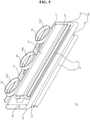
display device 100 may include thedisplay panel 110, amain frame 120, and aspeaker assembly 10. - The
display pane 110 may be provided on the front surface of thedisplay device 100 and may display images. - The
main frame 120 may be disposed at a rear portion of thedisplay panel 110. Themain frame 120 may be connected to thedisplay panel 110. - The
speaker assembly 10 may be disposed adjacent to a lower end of themain frame 120 to be installed at themain frame 120. Thespeaker assembly 10 may direct sound downwardly of thedisplay device 100. - Referring to
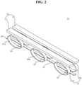
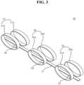
FIGS. 2 and3 , theplate 20 may be formed in the shape of a flat plate that extends long. For example, theplate 20 may be metal. In another example, theplate 20 may be a synthetic resin. Theplate 20 may include afirst plate 21 and asecond plate 22. Thefirst plate 21 may be parallel to thesecond plate 22 and may be spaced apart from thesecond plate 22. Theplate 20 may be referred to as arear plate 20. - An
elastic member 30 may support theplate 20. Theelastic member 30 may be connected or fixed to a lower part of theplate 20. Theelastic member 30 may be referred to as adamper 30. Theelastic member 30 may include acenter plate 31, bridges 32, 33, and 34, and circles 35, 36, and 37. For example, theelastic member 30 may be metal. In another example, theelastic member 30 may be a synthetic resin. - The
center plate 31 may extend long in a longitudinal direction of theplate 20 and may be disposed between thefirst plate 21 and thesecond plate 22. Thecenter plate 31 may be spaced apart from thefirst plate 21 and thesecond plate 22 at a position below thefirst plate 21 and thesecond plate 22. - The
bridges center plate 31, and may extend across thecenter plate 31. - The
circles bridges circles circles circles plate 20. - The
first bridge 32 may be disposed adjacent to one end of thecenter plate 31. Afirst circle 35a may be disposed on one end of thefirst bridge 32, and asecond circle 35b may be disposed on the other end of thefirst bridge 32. Thethird bridge 34 may be disposed adjacent to the other end of thecenter plate 31. Afifth circle 37a may be disposed on one end of thethird bridge 34, and asixth circle 37b may be disposed on the other end of thethird bridge 34. Thesecond bridge 33 may be disposed between thefirst bridge 32 and thethird bridge 34. Thethird circle 36a may be disposed on one end of thesecond bridge 36b, and thefourth circle 36b may be disposed on the other end of thesecond bridge 33. Thecircles bridges - The
first circle 35a may face thesecond circle 35b with respect to thecenter plate 31, thethird circle 36a may face thefourth circle 36b with respect to thecenter plate 31, and thefifth circle 37a may face thesixth circle 37b with respect to thecenter plate 31. - Accordingly, a range of motion of the
damper 30 may be increased or maximized relative to the size of thespeaker assembly 10. The range of motion of thedamper 30 may correlate to a reproduction band of thespeaker assembly 10, such that a sound reproduction band of thespeaker assembly 10 may be improved. In addition, sound pressure of thespeaker assembly 10 may also be improved. - Referring to
FIGS. 4 and5 ,magnets 40 may be disposed on therear plate 20. Themagnets 40 may have a square column shape that extends long. Afirst magnet 41 may be connected or fixed to an upper portion of the firstrear plate 21, and asecond magnet 42 may be connected or fixed to an upper portion of the secondrear plate 22. Thefirst magnet 41 may face thesecond magnet 42 with respect to thecenter plate 31. - A
plate 50 may extend long. Theplate 50 may be connected or fixed to an upper portion of themagnets 40. Theplate 50 may be referred to as afront plate 50. A firstfront plate 51 may be disposed on thefirst magnet 41, and the secondfront plate 52 may be disposed on thesecond magnet 42. The firstfront plate 51 may face the firstrear plate 21 with respect to thefirst magnet 41. The secondfront plate 52 may face the secondrear plate 22 with respect to thesecond magnet 42. - A
bobbin 81 may be formed in the shape of a flat plate that extends long. For example, thebobbin 81 may be a printed circuit board (PCB). Avoice coil 82 may be wound around thebobbin 81. Thevoice coil 82 may be wound around thebobbin 81 to form a closed-loop. For example, thevoice coil 82 may be printed on thebobbin 81. A vertical width Bw of thevoice coil 82 may be greater than a vertical width Mw of themagnets 40. Thebobbin 81 may be disposed between thefirst magnet 41 and thesecond magnet 42. When a current flows through thevoice coil 82, thebobbin 81 may move in a vertical direction. A lower end of thebobbin 81 may be connected or fixed to thecenter plate 31. - Referring to
FIGS. 5 and6 , aframe 60 may be formed in the shape of a flat plate that extends long. Theframe 60 may be connected or fixed to an upper portion of thefront plate 50. Afirst frame 61 may be disposed on the firstfront plate 51, and asecond frame 62 may be disposed on the secondfront plate 52. - A
speaker edge 70 may be connected or fixed to an upper portion of theframe 60. Thespeaker edge 70 may have elasticity. Thespeaker edge 70 may be formed in the shape of a cylinder that extends long. Thespeaker edge 70 may be formed in the shape of a cylinder cut in half. For example, thespeaker edge 70 may have a U-shaped cross-section. Afirst speaker edge 71 may be connected or fixed to an upper portion of thefirst frame 61, and asecond speaker edge 72 may be connected or fixed to an upper portion of thesecond frame 62. Thefirst speaker edge 71 may be convex toward thesecond speaker edge 72, and thesecond speaker edge 72 may be convex toward thefirst speaker edge 71. - A
diaphragm 90 may be formed in the shape of a plate that extends long. Thediaphragm 90 may be fixed to an upper end of thebobbin 81. One long side 90LS1 of thediaphragm 90 may be connected or fixed to thefirst speaker edge 71, and the other long side 90LS2 of thediaphragm 90 may be connected or fixed to thesecond speaker edge 72. Accordingly, an area of thediaphragm 90 may be maximized relative to a thickness of thespeaker assembly 10, and sound pressure may be improved. - Referring to
FIG. 7 , an outer surface of thefirst magnet 41 and an outer surface of thesecond magnet 42 may be exposed to the outside of thespeaker assembly 10. For example, a first distance D1 from the outer surface of thefirst magnet 41 to the outer surface of thesecond magnet 42 may be the thickness of thespeaker assembly 10. Outer surfaces of theplates magnets 40. The outer surfaces of theframes 60 may be aligned with respect to the outer surfaces of themagnets 40. - A second distance D2 between an outer surface of the first rear plate 211 and an outer surface of the second
rear plate 22 may be substantially equal to the first distance D1. A third distance D3 between an outer surface of the firstfront plate 51 and an outer surface of the secondfront plate 52 may be substantially equal to the first distance D1. - A fourth distance D4 between an outer surface of the first
front frame 61 and an outer surface of the secondfront frame 62 may be substantially equal to the first distance D1. A fifth distance D5 between an outer surface of the firstrear frame 63 and an outer surface of the secondrear frame 64 may be substantially equal to the first distance D1. - A sixth distance D6 between one long side of the
diaphragm 90 and the other long side of thediaphragm 90 may be substantially equal to the first distance D1. The sixth distance D6 may be substantially equal to the thickness of thespeaker assembly 10. Accordingly, sound pressure generated by thediaphragm 90 may be maximized. - Referring to
FIG. 8 , thebobbin 81 may move from the front frames 61 and 62 toward the rear frames 63 and 64. As thebobbin 81 moves, thediaphragm 90 may move closer to the front frames 61 and 62, and thespeaker edge 70 may be compressed. At the same time, thecircles damper 30 may be stretched in a longitudinal direction of thebobbin 81, such that a range of motion of thecircles damper 30 may be increased, and thus the amplitude of thediaphragm 90 may be increased. - Referring to
FIG. 9 , thebobbin 81 may move from the rear frames 63 and 64 toward the front frames 61 and 62. As thebobbin 81 moves, thediaphragm 90 may move further away from the front frames 61 and 62, and thespeaker edge 70 may be stretched. At the same time, thecircles damper 30 may be compressed in a longitudinal direction of thebobbin 81, such that a range of motion of thecircles damper 30 may be increased, and thus the amplitude of thediaphragm 90 may be increased. - Referring to
FIGS. 1 to 9 , the speaker assembly includes: a pair ofmagnets 40 facing each other; abobbin 81 disposed between the pair ofmagnets 40 and formed in a shape of a plate that extends long; acoil 82 formed on at least one surface of the bobbin; adiaphragm 90 fixed to one side of thebobbin 81, and extending in a direction intersecting a longitudinal direction of thebobbin 81; aframe 60 disposed between the pair ofmagnets 40 and thediaphragm 90; and aspeaker edge 70 disposed between theframe 60 and thediaphragm 90, having one end fixed to theframe 60 and the other end fixed to thediaphragm 90, and being convexly curved toward thebobbin 81. - The speaker assembly may further include a
damper 30 disposed to face theframe 60 with respect to the pair ofmagnets 40, fixed to the other side of thebobbin 81 which faces the one side of thebobbin 81, and providing elasticity to thebobbin 81. - The damper may include: a
center plate 31 extending long along the other side of thebobbin 81, and fixed to the other side of thebobbin 81;bridges center plate 31 and fixed to thecenter plate 31; and a plurality ofcircles bridges center plate 31. - The speaker assembly may further include a
rear plate 20 disposed between the pair ofmagnets 40 and the plurality ofcircles magnets 40 and the plurality ofcircles - The
speaker edge 70 may include: afirst speaker edge 71 having one end fixed to one side of thediaphragm 90 and the other end fixed to theframe 60, and being convexly curved toward thebobbin 81; and asecond speaker edge 72 having one end fixed to the other side of thediaphragm 90, which faces the one side of thediaphragm 90, and the other end fixed to theframe 60, and being convexly curved toward thebobbin 81. - The
first speaker edge 71 may be symmetrical to thesecond speaker edge 72 with respect to thebobbin 81. - The
rear plate 20 may include: a firstrear plate 21 disposed between one of the pair ofmagnets 40 and one of the plurality ofcircles rear plate 22 disposed between the other one of the pair ofmagnets 40 and another one of the plurality ofcircles rear plate 21 may include: a first surface connected to one of the pair ofmagnets 40; and a second surface connected to one of the plurality ofcircles - The
diaphragm 90 may include: a first long side connected to thefirst speaker edge 71; a second long side connected to thesecond speaker edge 72; a first short side connecting one end of the first long side and one end of the second long side; and a second short side connecting the other end of the first long side and the other end of the second long side, and facing the first short side. - The display device may include: a
display panel 110; aframe 120 connected to thedisplay panel 110; and the speaker assembly of Claim 1, which is disposed at a position adjacent to a lower end of theframe 120. - The
diaphragm 90 may have a length in a left-right direction of thedisplay panel 110 and may have a width in a thickness direction of thedisplay panel 110. - The speaker assembly, and the display device including the same according to the present disclosure have the following effects.
- According to at least one embodiment of the present disclosure, there is provided a speaker assembly capable of providing high sound quality.
- According to at least one embodiment of the present disclosure, there is provided a speaker assembly having a slim structure while maintaining a high sound pressure level.
- According to at least one embodiment of the present disclosure, there is provided a speaker assembly capable of increasing the amplitude of the speaker.
- The additional scope of applicability of the present disclosure will be apparent from the above detailed description. However, those skilled in the art will appreciate that various modifications and alterations are possible, without departing from the idea and scope of the present disclosure, and therefore it should be understood that the detailed description and specific embodiments, such as the preferred embodiments of the present disclosure, are provided only for illustration.
- Certain embodiments or other embodiments of the disclosure described above are not mutually exclusive or distinct from each other. Any or all elements of the embodiments of the disclosure described above may be combined or combined with each other in configuration or function.
- For example, a configuration "A" described in one embodiment of the disclosure and the drawings and a configuration "B" described in another embodiment of the disclosure and the drawings may be combined with each other. Namely, although the combination between the configurations is not directly described, the combination is possible except in the case where it is described that the combination is impossible.
Claims (10)
- A speaker assembly, comprising:a pair of magnets (40) facing each other;a bobbin (81) disposed between the pair of magnets (40) and formed in a shape of a plate that extends long;a coil (82) formed on at least one surface of the bobbin (81);a diaphragm (90) fixed to one side of the bobbin (81), and extending in a direction intersecting a longitudinal direction of the bobbin (81);a frame (60) disposed between the pair of magnets (40) and the diaphragm (90); anda speaker edge (70) disposed between the frame (60) and the diaphragm (90), having one end fixed to the frame (60) and the other end fixed to the diaphragm (90), and being convexly curved toward the bobbin (81).
- The speaker assembly of claim 1, further comprising a damper (30) disposed to face the frame (60) with respect to the pair of magnets (40), fixed to the other side of the bobbin (81) which faces the one side of the bobbin (81), and providing elasticity to the bobbin (81).
- The speaker assembly of claim 2, wherein the damper (30) comprises:a center plate (31) extending long along the other side of the bobbin (81), and fixed to the other side of the bobbin (81) ;bridges (32, 33, 34) disposed across the center plate (31) and fixed to the center plate (31); anda plurality of circles (35, 36, 37) fixed to both ends of the bridges (32, 33, 34) and disposed to face each other with respect to the center plate (31).
- The speaker assembly of claim 3, further comprising a rear plate (20) disposed between the pair of magnets (40) and the plurality of circles (35, 36, 37), and fixed to the pair of magnets (40) and the plurality of circles (35, 36, 37) .
- The speaker assembly of claim 4, wherein the speaker edge (70) comprises:a first speaker edge (71) having one end fixed to one side of the diaphragm (90) and the other end fixed to the frame (60), and being convexly curved toward the bobbin (81); anda second speaker edge (72) having one end fixed to the other side of the diaphragm (90), which faces the one side of the diaphragm (90), and the other end fixed to the frame (60), and being convexly curved toward the bobbin (81).
- The speaker assembly of claim 5, wherein the first speaker edge (71) is symmetrical to the second speaker edge (72) with respect to the bobbin (81).
- The speaker assembly of claim 6, wherein the rear plate (20) comprises:a first rear plate (21) disposed between one of the pair of magnets (40) and one of the plurality of circles (35, 36, 37); anda second rear plate (22) disposed between the other one of the pair of magnets (40) and another one of the plurality of circles (35, 36, 37),wherein the first rear plate (21) comprises:a first surface connected to one of the pair of magnets (40); anda second surface connected to one of the plurality of circles (35, 36, 37),wherein the first surface and the second surface face each other.
- The speaker assembly of claim 7, wherein the diaphragm (90) comprises:a first long side connected to the first speaker edge (71) ;a second long side connected to the second speaker edge (72) ;a first short side connecting one end of the first long side and one end of the second long side; anda second short side connecting the other end of the first long side and the other end of the second long side, and facing the first short side.
- A display device, comprising:a display panel (110);a frame (120) connected to the display panel (110); andthe speaker assembly of any one of Claims 1 to 8, which is disposed at a position adjacent to a lower end of the frame (120).
- The display device of claim 9, wherein the diaphragm (90) has a length in a left-right direction of the display panel (110) and has a width in a thickness direction of the display panel (110).
Applications Claiming Priority (1)
| Application Number | Priority Date | Filing Date | Title |
|---|---|---|---|
| KR1020200093827A KR102315588B1 (en) | 2020-07-28 | 2020-07-28 | Speaker assembly and display device comprising it |
Publications (2)
| Publication Number | Publication Date |
|---|---|
| EP3945730A1 true EP3945730A1 (en) | 2022-02-02 |
| EP3945730B1 EP3945730B1 (en) | 2024-12-18 |
Family
ID=74215828
Family Applications (1)
| Application Number | Title | Priority Date | Filing Date |
|---|---|---|---|
| EP21153188.4A Active EP3945730B1 (en) | 2020-07-28 | 2021-01-25 | Speaker assembly and display device comprising it |
Country Status (3)
| Country | Link |
|---|---|
| US (1) | US11632630B2 (en) |
| EP (1) | EP3945730B1 (en) |
| KR (1) | KR102315588B1 (en) |
Families Citing this family (2)
| Publication number | Priority date | Publication date | Assignee | Title |
|---|---|---|---|---|
| KR20230105128A (en) * | 2022-01-03 | 2023-07-11 | 삼성전자주식회사 | Display apparutus |
| WO2026043154A1 (en) * | 2024-08-20 | 2026-02-26 | 삼성전자주식회사 | Display apparatus |
Citations (7)
| Publication number | Priority date | Publication date | Assignee | Title |
|---|---|---|---|---|
| JP2002176693A (en) * | 2000-12-08 | 2002-06-21 | Matsushita Electric Ind Co Ltd | Speaker |
| JP2002223495A (en) * | 2001-01-29 | 2002-08-09 | Matsushita Electric Ind Co Ltd | Speaker |
| US20030103642A1 (en) * | 2001-11-30 | 2003-06-05 | Tai-Yan Kam | Rectangular transducer for panel-form loudspeaker |
| EP1950998A1 (en) * | 2007-01-29 | 2008-07-30 | Sony Corporation | Speaker unit and speaker apparatus |
| US20090257617A1 (en) * | 2008-04-15 | 2009-10-15 | Sony Corporation | Speaker, voice coil unit, and method of manufacturing the voice coil unit |
| US20180146294A1 (en) * | 2015-06-05 | 2018-05-24 | GOERTEK INC. No. | Vibration sound-producing apparatus |
| US10469954B1 (en) * | 2019-01-21 | 2019-11-05 | Zylux Acoustic Corporation | Thin speaker with a voice coil having a damper function |
Family Cites Families (9)
| Publication number | Priority date | Publication date | Assignee | Title |
|---|---|---|---|---|
| JPS6325824Y2 (en) * | 1980-07-10 | 1988-07-13 | ||
| JPS5734776U (en) * | 1980-07-31 | 1982-02-24 | ||
| JP3195516B2 (en) * | 1995-06-20 | 2001-08-06 | 株式会社ケンウッド | Repulsion magnetic circuit type speaker |
| TW507465B (en) * | 2000-12-28 | 2002-10-21 | Tai-Yan Kam | Transparent planar speaker |
| KR100671399B1 (en) * | 2005-04-08 | 2007-01-19 | 한국음향 주식회사 | speaker |
| KR101154252B1 (en) * | 2010-11-29 | 2012-06-13 | 주식회사 엑셀웨이 | Damper of voice coil plate for flat type speaker |
| KR101259399B1 (en) * | 2012-10-15 | 2013-04-30 | 범진아이엔디(주) | A speaker |
| CN204392554U (en) * | 2015-01-07 | 2015-06-10 | 瑞声光电科技(常州)有限公司 | Loud speaker |
| US9942663B1 (en) * | 2016-12-22 | 2018-04-10 | Apple Inc. | Electromagnetic transducer having paired Halbach arrays |
-
2020
- 2020-07-28 KR KR1020200093827A patent/KR102315588B1/en active Active
-
2021
- 2021-01-22 US US17/155,809 patent/US11632630B2/en active Active
- 2021-01-25 EP EP21153188.4A patent/EP3945730B1/en active Active
Patent Citations (7)
| Publication number | Priority date | Publication date | Assignee | Title |
|---|---|---|---|---|
| JP2002176693A (en) * | 2000-12-08 | 2002-06-21 | Matsushita Electric Ind Co Ltd | Speaker |
| JP2002223495A (en) * | 2001-01-29 | 2002-08-09 | Matsushita Electric Ind Co Ltd | Speaker |
| US20030103642A1 (en) * | 2001-11-30 | 2003-06-05 | Tai-Yan Kam | Rectangular transducer for panel-form loudspeaker |
| EP1950998A1 (en) * | 2007-01-29 | 2008-07-30 | Sony Corporation | Speaker unit and speaker apparatus |
| US20090257617A1 (en) * | 2008-04-15 | 2009-10-15 | Sony Corporation | Speaker, voice coil unit, and method of manufacturing the voice coil unit |
| US20180146294A1 (en) * | 2015-06-05 | 2018-05-24 | GOERTEK INC. No. | Vibration sound-producing apparatus |
| US10469954B1 (en) * | 2019-01-21 | 2019-11-05 | Zylux Acoustic Corporation | Thin speaker with a voice coil having a damper function |
Also Published As
| Publication number | Publication date |
|---|---|
| US20220038822A1 (en) | 2022-02-03 |
| KR102315588B1 (en) | 2021-10-20 |
| US11632630B2 (en) | 2023-04-18 |
| EP3945730B1 (en) | 2024-12-18 |
Similar Documents
| Publication | Publication Date | Title |
|---|---|---|
| US10681441B2 (en) | Display apparatus | |
| US8610842B2 (en) | Display apparatus | |
| EP4294048B1 (en) | Display apparatus and computing apparatus including the same | |
| CN103424913B (en) | curved display device | |
| US20110260960A1 (en) | Display Apparatus | |
| US12328546B2 (en) | Display apparatus | |
| KR102451998B1 (en) | Display device and fabricating mehtod of the same | |
| KR20230002223A (en) | Display device | |
| EP3945730B1 (en) | Speaker assembly and display device comprising it | |
| KR102560611B1 (en) | Display device | |
| EP3267243A1 (en) | Display device | |
| KR20210062338A (en) | Display device | |
| EP3009883A1 (en) | Narrow bezel flat panel display and method for manufacturing the same | |
| US20240388827A1 (en) | Display apparatus | |
| CN105842913A (en) | Display apparatus | |
| CN114265225A (en) | splicing display | |
| US9268175B2 (en) | Display device | |
| CN107577075B (en) | display device | |
| CN210722220U (en) | Display screen module and spliced screen | |
| AU2024203088B2 (en) | Display Device | |
| US12075203B2 (en) | Speaker assembly and display device having the same | |
| US11914240B2 (en) | Spliced display screen | |
| KR20190004954A (en) | Display device | |
| KR20180092660A (en) | Display device | |
| CN215769271U (en) | Light guide plate fixing structure |
Legal Events
| Date | Code | Title | Description |
|---|---|---|---|
| PUAI | Public reference made under article 153(3) epc to a published international application that has entered the european phase |
Free format text: ORIGINAL CODE: 0009012 |
|
| STAA | Information on the status of an ep patent application or granted ep patent |
Free format text: STATUS: REQUEST FOR EXAMINATION WAS MADE |
|
| 17P | Request for examination filed |
Effective date: 20210225 |
|
| AK | Designated contracting states |
Kind code of ref document: A1 Designated state(s): AL AT BE BG CH CY CZ DE DK EE ES FI FR GB GR HR HU IE IS IT LI LT LU LV MC MK MT NL NO PL PT RO RS SE SI SK SM TR |
|
| STAA | Information on the status of an ep patent application or granted ep patent |
Free format text: STATUS: EXAMINATION IS IN PROGRESS |
|
| 17Q | First examination report despatched |
Effective date: 20230411 |
|
| GRAP | Despatch of communication of intention to grant a patent |
Free format text: ORIGINAL CODE: EPIDOSNIGR1 |
|
| STAA | Information on the status of an ep patent application or granted ep patent |
Free format text: STATUS: GRANT OF PATENT IS INTENDED |
|
| RIC1 | Information provided on ipc code assigned before grant |
Ipc: H04R 9/04 20060101ALN20240711BHEP Ipc: H04R 9/06 20060101AFI20240711BHEP |
|
| INTG | Intention to grant announced |
Effective date: 20240719 |
|
| GRAS | Grant fee paid |
Free format text: ORIGINAL CODE: EPIDOSNIGR3 |
|
| GRAA | (expected) grant |
Free format text: ORIGINAL CODE: 0009210 |
|
| STAA | Information on the status of an ep patent application or granted ep patent |
Free format text: STATUS: THE PATENT HAS BEEN GRANTED |
|
| AK | Designated contracting states |
Kind code of ref document: B1 Designated state(s): AL AT BE BG CH CY CZ DE DK EE ES FI FR GB GR HR HU IE IS IT LI LT LU LV MC MK MT NL NO PL PT RO RS SE SI SK SM TR |
|
| REG | Reference to a national code |
Ref country code: CH Ref legal event code: EP |
|
| REG | Reference to a national code |
Ref country code: DE Ref legal event code: R096 Ref document number: 602021023409 Country of ref document: DE |
|
| REG | Reference to a national code |
Ref country code: IE Ref legal event code: FG4D |
|
| REG | Reference to a national code |
Ref country code: LT Ref legal event code: MG9D |
|
| PG25 | Lapsed in a contracting state [announced via postgrant information from national office to epo] |
Ref country code: HR Free format text: LAPSE BECAUSE OF FAILURE TO SUBMIT A TRANSLATION OF THE DESCRIPTION OR TO PAY THE FEE WITHIN THE PRESCRIBED TIME-LIMIT Effective date: 20241218 |
|
| PG25 | Lapsed in a contracting state [announced via postgrant information from national office to epo] |
Ref country code: FI Free format text: LAPSE BECAUSE OF FAILURE TO SUBMIT A TRANSLATION OF THE DESCRIPTION OR TO PAY THE FEE WITHIN THE PRESCRIBED TIME-LIMIT Effective date: 20241218 |
|
| PG25 | Lapsed in a contracting state [announced via postgrant information from national office to epo] |
Ref country code: BG Free format text: LAPSE BECAUSE OF FAILURE TO SUBMIT A TRANSLATION OF THE DESCRIPTION OR TO PAY THE FEE WITHIN THE PRESCRIBED TIME-LIMIT Effective date: 20241218 |
|
| PG25 | Lapsed in a contracting state [announced via postgrant information from national office to epo] |
Ref country code: NO Free format text: LAPSE BECAUSE OF FAILURE TO SUBMIT A TRANSLATION OF THE DESCRIPTION OR TO PAY THE FEE WITHIN THE PRESCRIBED TIME-LIMIT Effective date: 20250318 |
|
| REG | Reference to a national code |
Ref country code: NL Ref legal event code: MP Effective date: 20241218 |
|
| PG25 | Lapsed in a contracting state [announced via postgrant information from national office to epo] |
Ref country code: LV Free format text: LAPSE BECAUSE OF FAILURE TO SUBMIT A TRANSLATION OF THE DESCRIPTION OR TO PAY THE FEE WITHIN THE PRESCRIBED TIME-LIMIT Effective date: 20241218 Ref country code: GR Free format text: LAPSE BECAUSE OF FAILURE TO SUBMIT A TRANSLATION OF THE DESCRIPTION OR TO PAY THE FEE WITHIN THE PRESCRIBED TIME-LIMIT Effective date: 20250319 |
|
| PG25 | Lapsed in a contracting state [announced via postgrant information from national office to epo] |
Ref country code: RS Free format text: LAPSE BECAUSE OF FAILURE TO SUBMIT A TRANSLATION OF THE DESCRIPTION OR TO PAY THE FEE WITHIN THE PRESCRIBED TIME-LIMIT Effective date: 20250318 |
|
| PG25 | Lapsed in a contracting state [announced via postgrant information from national office to epo] |
Ref country code: NL Free format text: LAPSE BECAUSE OF FAILURE TO SUBMIT A TRANSLATION OF THE DESCRIPTION OR TO PAY THE FEE WITHIN THE PRESCRIBED TIME-LIMIT Effective date: 20241218 |
|
| REG | Reference to a national code |
Ref country code: AT Ref legal event code: MK05 Ref document number: 1753235 Country of ref document: AT Kind code of ref document: T Effective date: 20241218 |
|
| PG25 | Lapsed in a contracting state [announced via postgrant information from national office to epo] |
Ref country code: SM Free format text: LAPSE BECAUSE OF FAILURE TO SUBMIT A TRANSLATION OF THE DESCRIPTION OR TO PAY THE FEE WITHIN THE PRESCRIBED TIME-LIMIT Effective date: 20241218 |
|
| PG25 | Lapsed in a contracting state [announced via postgrant information from national office to epo] |
Ref country code: PL Free format text: LAPSE BECAUSE OF FAILURE TO SUBMIT A TRANSLATION OF THE DESCRIPTION OR TO PAY THE FEE WITHIN THE PRESCRIBED TIME-LIMIT Effective date: 20241218 |
|
| PG25 | Lapsed in a contracting state [announced via postgrant information from national office to epo] |
Ref country code: ES Free format text: LAPSE BECAUSE OF FAILURE TO SUBMIT A TRANSLATION OF THE DESCRIPTION OR TO PAY THE FEE WITHIN THE PRESCRIBED TIME-LIMIT Effective date: 20241218 |
|
| PG25 | Lapsed in a contracting state [announced via postgrant information from national office to epo] |
Ref country code: IS Free format text: LAPSE BECAUSE OF FAILURE TO SUBMIT A TRANSLATION OF THE DESCRIPTION OR TO PAY THE FEE WITHIN THE PRESCRIBED TIME-LIMIT Effective date: 20250418 |
|
| PG25 | Lapsed in a contracting state [announced via postgrant information from national office to epo] |
Ref country code: PT Free format text: LAPSE BECAUSE OF FAILURE TO SUBMIT A TRANSLATION OF THE DESCRIPTION OR TO PAY THE FEE WITHIN THE PRESCRIBED TIME-LIMIT Effective date: 20250421 |
|
| PG25 | Lapsed in a contracting state [announced via postgrant information from national office to epo] |
Ref country code: EE Free format text: LAPSE BECAUSE OF FAILURE TO SUBMIT A TRANSLATION OF THE DESCRIPTION OR TO PAY THE FEE WITHIN THE PRESCRIBED TIME-LIMIT Effective date: 20241218 |
|
| PG25 | Lapsed in a contracting state [announced via postgrant information from national office to epo] |
Ref country code: RO Free format text: LAPSE BECAUSE OF FAILURE TO SUBMIT A TRANSLATION OF THE DESCRIPTION OR TO PAY THE FEE WITHIN THE PRESCRIBED TIME-LIMIT Effective date: 20241218 Ref country code: AT Free format text: LAPSE BECAUSE OF FAILURE TO SUBMIT A TRANSLATION OF THE DESCRIPTION OR TO PAY THE FEE WITHIN THE PRESCRIBED TIME-LIMIT Effective date: 20241218 |
|
| PG25 | Lapsed in a contracting state [announced via postgrant information from national office to epo] |
Ref country code: SK Free format text: LAPSE BECAUSE OF FAILURE TO SUBMIT A TRANSLATION OF THE DESCRIPTION OR TO PAY THE FEE WITHIN THE PRESCRIBED TIME-LIMIT Effective date: 20241218 |
|
| PG25 | Lapsed in a contracting state [announced via postgrant information from national office to epo] |
Ref country code: CZ Free format text: LAPSE BECAUSE OF FAILURE TO SUBMIT A TRANSLATION OF THE DESCRIPTION OR TO PAY THE FEE WITHIN THE PRESCRIBED TIME-LIMIT Effective date: 20241218 |
|
| PG25 | Lapsed in a contracting state [announced via postgrant information from national office to epo] |
Ref country code: IT Free format text: LAPSE BECAUSE OF FAILURE TO SUBMIT A TRANSLATION OF THE DESCRIPTION OR TO PAY THE FEE WITHIN THE PRESCRIBED TIME-LIMIT Effective date: 20241218 |
|
| REG | Reference to a national code |
Ref country code: CH Ref legal event code: PL |
|
| PG25 | Lapsed in a contracting state [announced via postgrant information from national office to epo] |
Ref country code: SE Free format text: LAPSE BECAUSE OF FAILURE TO SUBMIT A TRANSLATION OF THE DESCRIPTION OR TO PAY THE FEE WITHIN THE PRESCRIBED TIME-LIMIT Effective date: 20241218 |
|
| PG25 | Lapsed in a contracting state [announced via postgrant information from national office to epo] |
Ref country code: LU Free format text: LAPSE BECAUSE OF NON-PAYMENT OF DUE FEES Effective date: 20250125 Ref country code: MC Free format text: LAPSE BECAUSE OF FAILURE TO SUBMIT A TRANSLATION OF THE DESCRIPTION OR TO PAY THE FEE WITHIN THE PRESCRIBED TIME-LIMIT Effective date: 20241218 |
|
| REG | Reference to a national code |
Ref country code: DE Ref legal event code: R097 Ref document number: 602021023409 Country of ref document: DE |
|
| PG25 | Lapsed in a contracting state [announced via postgrant information from national office to epo] |
Ref country code: DK Free format text: LAPSE BECAUSE OF FAILURE TO SUBMIT A TRANSLATION OF THE DESCRIPTION OR TO PAY THE FEE WITHIN THE PRESCRIBED TIME-LIMIT Effective date: 20241218 |
|
| PG25 | Lapsed in a contracting state [announced via postgrant information from national office to epo] |
Ref country code: BE Free format text: LAPSE BECAUSE OF NON-PAYMENT OF DUE FEES Effective date: 20250131 |
|
| PG25 | Lapsed in a contracting state [announced via postgrant information from national office to epo] |
Ref country code: CH Free format text: LAPSE BECAUSE OF NON-PAYMENT OF DUE FEES Effective date: 20250131 |
|
| REG | Reference to a national code |
Ref country code: BE Ref legal event code: MM Effective date: 20250131 |
|
| PLBE | No opposition filed within time limit |
Free format text: ORIGINAL CODE: 0009261 |
|
| STAA | Information on the status of an ep patent application or granted ep patent |
Free format text: STATUS: NO OPPOSITION FILED WITHIN TIME LIMIT |
|
| 26N | No opposition filed |
Effective date: 20250919 |
|
| PGFP | Annual fee paid to national office [announced via postgrant information from national office to epo] |
Ref country code: GB Payment date: 20251208 Year of fee payment: 6 |
|
| PGFP | Annual fee paid to national office [announced via postgrant information from national office to epo] |
Ref country code: FR Payment date: 20251209 Year of fee payment: 6 |
|
| PG25 | Lapsed in a contracting state [announced via postgrant information from national office to epo] |
Ref country code: IE Free format text: LAPSE BECAUSE OF NON-PAYMENT OF DUE FEES Effective date: 20250125 |
|
| PGFP | Annual fee paid to national office [announced via postgrant information from national office to epo] |
Ref country code: DE Payment date: 20251208 Year of fee payment: 6 |