EP3945705A1 - System and method for identifying compromised electronic controller using intentionally induced error - Google Patents
System and method for identifying compromised electronic controller using intentionally induced error Download PDFInfo
- Publication number
- EP3945705A1 EP3945705A1 EP21176220.8A EP21176220A EP3945705A1 EP 3945705 A1 EP3945705 A1 EP 3945705A1 EP 21176220 A EP21176220 A EP 21176220A EP 3945705 A1 EP3945705 A1 EP 3945705A1
- Authority
- EP
- European Patent Office
- Prior art keywords
- ecu
- bus
- message
- time
- compromised
- Prior art date
- Legal status (The legal status is an assumption and is not a legal conclusion. Google has not performed a legal analysis and makes no representation as to the accuracy of the status listed.)
- Granted
Links
Images





Classifications
-
- G—PHYSICS
- G06—COMPUTING OR CALCULATING; COUNTING
- G06F—ELECTRIC DIGITAL DATA PROCESSING
- G06F21/00—Security arrangements for protecting computers, components thereof, programs or data against unauthorised activity
- G06F21/50—Monitoring users, programs or devices to maintain the integrity of platforms, e.g. of processors, firmware or operating systems
- G06F21/55—Detecting local intrusion or implementing counter-measures
- G06F21/56—Computer malware detection or handling, e.g. anti-virus arrangements
- G06F21/566—Dynamic detection, i.e. detection performed at run-time, e.g. emulation, suspicious activities
-
- H—ELECTRICITY
- H04—ELECTRIC COMMUNICATION TECHNIQUE
- H04L—TRANSMISSION OF DIGITAL INFORMATION, e.g. TELEGRAPHIC COMMUNICATION
- H04L63/00—Network architectures or network communication protocols for network security
- H04L63/14—Network architectures or network communication protocols for network security for detecting or protecting against malicious traffic
- H04L63/1441—Countermeasures against malicious traffic
-
- G—PHYSICS
- G05—CONTROLLING; REGULATING
- G05B—CONTROL OR REGULATING SYSTEMS IN GENERAL; FUNCTIONAL ELEMENTS OF SUCH SYSTEMS; MONITORING OR TESTING ARRANGEMENTS FOR SUCH SYSTEMS OR ELEMENTS
- G05B23/00—Testing or monitoring of control systems or parts thereof
- G05B23/02—Electric testing or monitoring
- G05B23/0205—Electric testing or monitoring by means of a monitoring system capable of detecting and responding to faults
- G05B23/0208—Electric testing or monitoring by means of a monitoring system capable of detecting and responding to faults characterized by the configuration of the monitoring system
- G05B23/0213—Modular or universal configuration of the monitoring system, e.g. monitoring system having modules that may be combined to build monitoring program; monitoring system that can be applied to legacy systems; adaptable monitoring system; using different communication protocols
-
- H—ELECTRICITY
- H04—ELECTRIC COMMUNICATION TECHNIQUE
- H04L—TRANSMISSION OF DIGITAL INFORMATION, e.g. TELEGRAPHIC COMMUNICATION
- H04L12/00—Data switching networks
- H04L12/28—Data switching networks characterised by path configuration, e.g. LAN [Local Area Networks] or WAN [Wide Area Networks]
- H04L12/40—Bus networks
-
- H—ELECTRICITY
- H04—ELECTRIC COMMUNICATION TECHNIQUE
- H04L—TRANSMISSION OF DIGITAL INFORMATION, e.g. TELEGRAPHIC COMMUNICATION
- H04L12/00—Data switching networks
- H04L12/28—Data switching networks characterised by path configuration, e.g. LAN [Local Area Networks] or WAN [Wide Area Networks]
- H04L12/40—Bus networks
- H04L12/40006—Architecture of a communication node
- H04L12/40013—Details regarding a bus controller
-
- H—ELECTRICITY
- H04—ELECTRIC COMMUNICATION TECHNIQUE
- H04L—TRANSMISSION OF DIGITAL INFORMATION, e.g. TELEGRAPHIC COMMUNICATION
- H04L63/00—Network architectures or network communication protocols for network security
- H04L63/14—Network architectures or network communication protocols for network security for detecting or protecting against malicious traffic
- H04L63/1408—Network architectures or network communication protocols for network security for detecting or protecting against malicious traffic by monitoring network traffic
- H04L63/1425—Traffic logging, e.g. anomaly detection
-
- G—PHYSICS
- G05—CONTROLLING; REGULATING
- G05B—CONTROL OR REGULATING SYSTEMS IN GENERAL; FUNCTIONAL ELEMENTS OF SUCH SYSTEMS; MONITORING OR TESTING ARRANGEMENTS FOR SUCH SYSTEMS OR ELEMENTS
- G05B2219/00—Program-control systems
- G05B2219/20—Pc systems
- G05B2219/24—Pc safety
- G05B2219/24065—Real time diagnostics
-
- G—PHYSICS
- G06—COMPUTING OR CALCULATING; COUNTING
- G06F—ELECTRIC DIGITAL DATA PROCESSING
- G06F2221/00—Indexing scheme relating to security arrangements for protecting computers, components thereof, programs or data against unauthorised activity
- G06F2221/03—Indexing scheme relating to G06F21/50, monitoring users, programs or devices to maintain the integrity of platforms
- G06F2221/034—Test or assess a computer or a system
-
- H—ELECTRICITY
- H04—ELECTRIC COMMUNICATION TECHNIQUE
- H04L—TRANSMISSION OF DIGITAL INFORMATION, e.g. TELEGRAPHIC COMMUNICATION
- H04L12/00—Data switching networks
- H04L12/28—Data switching networks characterised by path configuration, e.g. LAN [Local Area Networks] or WAN [Wide Area Networks]
- H04L12/40—Bus networks
- H04L2012/40208—Bus networks characterized by the use of a particular bus standard
- H04L2012/40215—Controller Area Network CAN
-
- H—ELECTRICITY
- H04—ELECTRIC COMMUNICATION TECHNIQUE
- H04L—TRANSMISSION OF DIGITAL INFORMATION, e.g. TELEGRAPHIC COMMUNICATION
- H04L12/00—Data switching networks
- H04L12/28—Data switching networks characterised by path configuration, e.g. LAN [Local Area Networks] or WAN [Wide Area Networks]
- H04L12/40—Bus networks
- H04L2012/40267—Bus for use in transportation systems
- H04L2012/40273—Bus for use in transportation systems the transportation system being a vehicle
Definitions
- the present disclosure relates to identifying a compromised controller in an in-vehicle network.
- an attacker takes control of one of the Electronic Control Units (ECUs) and can use a counterfeited or compromised ECU to pretend to be another one of the ECUs by broadcasting messages seemingly generated by the another one of the ECUs over the network.
- ECUs Electronic Control Units
- IDS detects a CAN security attack, to get a restoration, for example, to have the normal patch or update of the compromised ECU used in the spoofing attack is premised on the identification of the compromised ECU.
- Developed related art includes a technology for identifying an ECU by using the characteristics of a power signal flowing through a CAN bus when the ECU transmits a message.
- This technology requires additional high-performance hardware to measure the power signal and susceptible to the vulnerability of the power signal as being sensitive to changes in external elements such as temperature, electromagnetic field, and model year.
- Additional related art discloses a technology for identifying an ECU by using physical properties of the ECU, such as the clock skew of a CAN message transmitted on a CAN bus. This technique is difficult to accurately identify the compromised ECU when it emulates the clock skew of another ECU.
- the year 2016 saw a report of a bus-off attack as a new Denial of Service (DoS) attack on the CAN bus.
- DoS Denial of Service
- the attacker uses the CAN protocol's fault confinement mechanisms to transition the target ECU to a bus-off state, making it impossible to send and receive messages.
- the present disclosure provides a method, performed by an electronic device (120) in a controller area network, CAN, for identifying a compromised electronic control unit, ECU, that transmits an attack message on a CAN bus in a periodic transmission cycle, including in response to detecting the attack message, transitioning a first ECU among a plurality of ECUs connected to the CAN bus to a bus-off state intentionally, and determining whether the first ECU is the compromised ECU based at least in part on a time, which is predicted from recovery parameters related to the first ECU, for when the first ECU resumes a transmission of a CAN message and a time when the attack message is redetected on the CAN bus.
- the transitioning to the bus-off state may include transmitting a diagnosis request message corresponding to the first ECU, monitoring the CAN bus to detect an initiation of transmission of a diagnosis response message by the first ECU, and in response to detecting the initiation of transmission of the diagnosis response message, causing a transmission error in the diagnosis response message by transmitting a plurality of dominant bits to the CAN bus until the first ECU transitions to the bus-off state.
- the determining whether the first ECU is the compromised ECU may include predicting, as a predicted transmission resumption time, the time for when the first ECU resumes the transmission of the CAN message by using the recovery parameters related to the first ECU, and determining that the first ECU is the compromised ECU in response to determining that a difference between the predicted transmission resumption time and the time when the attack message is redetected on the CAN bus is less than or equal to a preset threshold time.
- the method may further include in response to determining that the difference between the predicted transmission resumption time and the time when the attack message is redetected on the CAN bus is greater than the preset threshold time, transitioning a second ECU different from the first ECU to a bus-off state intentionally, and determining whether the second ECU is the compromised ECU based at least in part on a time, which is predicted from recovery parameters related to the second ECU, for when the second ECU resumes a transmission of a CAN message and a time when the attack message is redetected on the CAN bus.
- the determining whether the first ECU is the compromised ECU may include calculating, as a calculated recovery time, a time for when the first ECU recovers from the bus-off state by using the recovery parameters related to the first ECU, and determining whether the first ECU is the compromised ECU based on whether the attack message is redetected on the CAN bus before the calculated recovery time.
- the transitioning of the first ECU to the bus-off state may include transitioning the first ECU to the bus-off state repeatedly to prevent the transmission of the CAN message by the first ECU for a period greater than the periodic transmission cycle of the attack message, and the determining whether the first ECU is the compromised ECU may include determining whether the first ECU is the compromised ECU based on whether the attack message is redetected on the CAN bus while the first ECU is in the bus-off state.
- the present disclosure provides a method, performed by an electronic device in a controller area network, CAN, for analyzing recovery parameters related to a recovery of an electronic control unit, ECU, connected to a CAN bus, from a bus-off state, including transitioning the ECU that periodically transmits a controller area network message, CAN message, to the bus-off state intentionally, and monitoring the CAN bus to receive the CAN message that is resumed to be transmitted following the recovery of the ECU from the bus-off state, and analyzing the recovery parameters of the ECU based in part on a time when the CAN message is received.
- the transitioning of the ECU to the bus-off state may include transmitting a diagnosis request message corresponding to the ECU, monitoring the CAN bus to detect an initiation of transmission of a diagnosis response message by the ECU, and in response to detecting the initiation of transmission of the diagnosis response message, causing a transmission error in the diagnosis response message by transmitting a plurality of dominant bits to the CAN bus until the ECU transitions to the bus-off state.
- the analyzing the recovery parameters may include analyzing the recovery parameters, including a Wait Time, a Controller Recovery Type, and a Timer Behavior of the ECU based on at least one of a time when the ECU transmits a last CAN message before the ECU transitions to the bus-off state, a time when the ECU transitions to the bus-off state, and a time when the ECU transmits a first CAN message after the ECU recovers from the bus-off state.
- the method may further include storing the recovery parameters non-transiently.
- the present disclosure provides an electronic device (120) for identifying a compromised electronic control unit, ECU, that transmits an attack message on a controller area network bus, CAN bus, in a periodic transmission cycle, the electronic device including an error generating unit (200) and a compromised-ECU identification unit (240).
- the error generating unit (200) is configured to, in response to detecting the attack message, transition a first ECU among a plurality of ECUs connected to the CAN bus to a bus-off state intentionally.
- the compromised-ECU identification unit (240) is configured to determine whether the first ECU is the compromised ECU based at least in part on a time, which is predicted from recovery parameters related to the first ECU, for when the first ECU resumes a transmission of a CAN message and a time when the attack message is redetected on the CAN bus.
- the error generating unit (200) may be configured to transmit a diagnosis request message corresponding to the first ECU, monitor the CAN bus to detect an initiation of transmission of a diagnosis response message by the first ECU, and in response to detecting the initiation of transmission of the diagnosis response message, cause a transmission error in the diagnosis response message by transmitting a plurality of dominant bits to the CAN bus until the first ECU transitions to the bus-off state.
- the compromised-ECU identification unit (240) may be configured to predict, as a predicted transmission resumption time, the time for when the first ECU resumes the transmission of the CAN message by using the recovery parameters related to the first ECU, and determine that the first ECU is the compromised ECU in response to determining that a difference between the predicted transmission resumption time and the time when the attack message is redetected on the CAN bus is less than or equal to a preset threshold time.
- the error generating unit (200) may be configured to, in response to determining that the difference between the predicted transmission resumption time and the time when the attack message is redetected on the CAN bus is greater than the preset threshold time, transition a second ECU different from the first ECU to a bus-off state intentionally, and the compromised-ECU identification unit (240) may be configured to determine whether the second ECU is the compromised ECU based at least in part on a time, which is predicted from recovery parameters related to the second ECU, for when the second ECU resumes a transmission of a CAN message and a time when the attack message is redetected on the CAN bus.
- the compromised-ECU identification unit (240) may be configured to calculate, as a calculated recovery time, a time for when the first ECU recovers from the bus-off state by using the recovery parameters related to the first ECU, and determine whether the first ECU is the compromised ECU based on whether the attack message is redetected on the CAN bus before the calculated recovery time.
- the error generating unit (200) may be configured to transition the first ECU to the bus-off state repeatedly to prevent the transmission of the CAN message by the first ECU for a period greater than the periodic transmission cycle of the attack message, and the compromised-ECU identification unit (240) may be configured to determine whether the first ECU is a compromised ECU based on whether the attack message is redetected on the CAN bus while the first ECU is in the bus-off state.
- the present disclosure provides an electronic device for analyzing recovery parameters related to a recovery of an electronic control unit ,ECU, connected to a controller area network bus, CAN bus, from a bus-off state, the electronic device including an error generating unit (200) and a parameter analysis unit (210).
- the error generating unit (200) is configured to transition the ECU that periodically transmits a controller area network message, CAN message, to the bus-off state intentionally.
- the parameter analysis unit (210) is configured to monitor the CAN bus to receive the CAN message that is resumed to be transmitted following the recovery of the ECU from the bus-off state, and to analyze the recovery parameters of the ECU based in part on a time when the CAN message is received.
- the error generating unit (200) may be configured to transmit a diagnosis request message corresponding to the ECU, monitor the CAN bus to detect an initiation of transmission of a diagnosis response message by the ECU, and in response to detecting the initiation of transmission of the diagnosis response message for causing a transmission error in the diagnosis response message by transmitting a plurality of dominant bits to the CAN bus until the ECU transitions to the bus-off state.
- the parameter analysis unit (210) may be configured to analyze the recovery parameters, including a Wait Time, a Controller Recovery Type, and a Timer Behavior of the ECU, based on at least one of a time when the ECU transmits a last CAN message before the ECU transitions to the bus-off state, a time when the ECU transitions to the bus-off state, and a time when the ECU transmits a first CAN message after the ECU recovers from the bus-off state.
- the parameter analysis unit (210) may be configured to store the recovery parameters non-transiently by associating the recovery parameters with the ECU.
- vehicle or “vehicular” or other similar term as used herein is inclusive of motor vehicles in general such as passenger automobiles including sports utility vehicles (SUV), buses, trucks, various commercial vehicles, watercraft including a variety of boats and ships, aircraft, and the like, and includes hybrid vehicles, electric vehicles, combustion, plug-in hybrid electric vehicles, hydrogen-powered vehicles and other alternative fuel vehicles (e.g. fuels derived from resources other than petroleum).
- motor vehicles in general such as passenger automobiles including sports utility vehicles (SUV), buses, trucks, various commercial vehicles, watercraft including a variety of boats and ships, aircraft, and the like, and includes hybrid vehicles, electric vehicles, combustion, plug-in hybrid electric vehicles, hydrogen-powered vehicles and other alternative fuel vehicles (e.g. fuels derived from resources other than petroleum).
- SUV sports utility vehicles
- plug-in hybrid electric vehicles e.g. fuels derived from resources other than petroleum
- Some exemplary embodiments of the present disclosure provide methods and systems for identifying a compromised controller being used for an attack on a CAN network by using fault confinement mechanisms of the CAN protocol.
- various terms such as first, second, A, B, (a), (b), etc. are used solely to differentiate one component from the other but not to imply or suggest the substances, order, or sequence of the components.
- a part 'includes' or 'comprises' a component the part is meant to further include other components, not to exclude thereof unless specifically stated to the contrary.
- the terms such as 'unit', 'module', and the like refer to one or more units for processing at least one function or operation, which may be implemented by hardware, software, or a combination thereof.
- CAN protocol Controller Area Network Protocol
- Each ECU (Electronic Control Unit) connected on the CAN bus has a Transmit Error Count (TEC) and Receive Error Count (REC) that increase or decrease with a specific weight according to the success of message transmission or reception or occurrence of an error.
- the state of the ECU is defined based on TEC and REC. In particular, when the TEC is equal to or greater than 256, the ECU transitions to a state in which it cannot transmit and receive any messages on the CAN bus. This state is referred to as a bus-off state.
- the return of the ECU from the bus-off state back to the active state capable of participating in CAN communications is referred to as recovery.
- the ECU may recover from the bus-off state by monitoring 128 consecutive 11 recessive bits. In an actual operating environment, an additional time of tens to hundreds of milliseconds is required for each ECU.
- some exemplary embodiments of the present disclosure provide a method and system for forcibly transitioning the ECU to the bus-off state and using the characteristics appearing in the recovery process to identify the ECU.
- FIG. 1 is a block diagram schematically showing a CAN system according to at least one exemplary embodiment of the present disclosure.
- the CAN system 10 may include all or some of at least one of ECUs 100 to 106, an Intrusion Detection System (IDS) 110, an ECU identification apparatus 120, and an ECU update apparatus 130.
- IDS Intrusion Detection System
- ECU identification apparatus 120 ECU identification apparatus 120
- ECU update apparatus 130 not all blocks shown in FIG. 1 are essential components, and some blocks included in the CAN system 10 may be added, changed, or deleted in other exemplary embodiments.
- the ECUs 100 to 106 are electronic devices having a CAN communication function and are configured to transmit an ordinary CAN message and/or an attack CAN message on a CAN bus in a periodic transmission cycle.
- the IDS 110 may be configured to detect an attack that occurred on the CAN bus. In response to detecting an attack on the CAN bus, the IDS 110 may be configured to transmit identification initiation information to the ECU identification apparatus 120.
- the identification initiation information may include the IDentification (ID) of the attack CAN message and/or the transmission period of the attack CAN message.
- the ECU identification device 120 may be a separate electronic device accessible to the CAN bus, or may be included as a functional module in an electronic device implementing the IDS 110.
- the ECU identification apparatus 120 may be configured to analyze and store the recovery parameters corresponding to the respective ECUs 100 to 106, and identify the ECU using the recovery parameters.
- the ECU identification apparatus 120 may be configured to analyze and store recovery parameters corresponding to the respective ECUs 100 to 106 before the IDS 110 detects an attack. In response to the IDS 110 detecting an attack and transmitting the identification initiation information to the ECU identification apparatus 120, the latter utilizes the recovery parameters to identify the compromised ECU that performs the attack.
- the ECU identification apparatus 120 may be configured to receive and store recovery parameters corresponding to the respective ECUs 100 to 106 from an externally connected ECU analysis apparatus (not shown). A detailed description of the ECU identification apparatus 120 will be presented with reference to FIG. 2 .
- the ECU update apparatus 130 may be configured to restore the compromised ECU to a normal ECU by performing an update of the compromised ECU identified by the ECU identification apparatus 120.
- the IDS or the ECU update apparatus in the present disclosure encompasses all IDSs or ECU update apparatus that may be easily employed by a person skilled in the art, and the IDS or the ECU update apparatus is not limited to having a specific configuration and/or function.
- FIG. 2 is a block diagram schematically showing an ECU identification apparatus according to at least one exemplary embodiment of the present disclosure.
- the ECU identification apparatus 120 may include all or some of an error generating unit 200, a parameter analysis unit 210, a parameter storage unit 220, a calculation unit 230, and the compromised-ECU identification unit 240.
- Not all blocks shown in FIG. 2 are essential components, and some blocks included in the ECU identification apparatus 120 may be added, changed, or deleted in other embodiments.
- the ECU identification apparatus 120 may not include the parameter analysis unit 210 if it receives recovery parameters from its interworked ECU analysis apparatus that is a separate stand-alone apparatus.
- the ECU analysis apparatus may include all or some of the error generation unit 200 and the parameter analysis unit 210.
- the error generating unit 200 causes an error on the CAN bus to transition the ECU to the bus-off state.
- the error generating unit 200 may transition the target ECU to a bus-off state using an ECU diagnosis protocol.
- the target ECU refers to an analysis target ECU for which recovery parameters are analyzed or an identification target ECU to be checked whether it is identified as a compromised ECU.
- FIG. 3 is a diagram illustrating a method of transitioning an ECU to a bus-off state according to at least one exemplary embodiment of the present disclosure.
- a diagnosis request ID and a diagnosis response ID are defined, corresponding to each ECU.
- a diagnosis request ID and a diagnosis response ID may be defined in a range of 0x700 or more.
- DQ_ID N and DR_ID N respectively denote a diagnosis request ID and a diagnosis response ID corresponding to the target ECU transmitting an CAN message on a CAN bus in a periodic transmission cycle.
- ID N and T respectively denote the ID and the period of the CAN message. As shown in FIG.
- the target ECU in response to the error generating unit 200 transmitting on a CAN bus a diagnosis request message including a diagnosis request ID (DQ_ID N ), the target ECU may be configured to transmit on the CAN bus a diagnosis response message including a diagnosis response ID (DR_ID N ).
- the error generating unit 200 may be configured to transmit the diagnosis request message corresponding to the target ECU, monitor the CAN bus to detect the initiation of transmission of the diagnosis response message by the target ECU, and in response to a detection of the initiation of transmission of the diagnosis response message by the target ECU, transmit a plurality of dominant bits on the CAN bus, causing a transmission error to occur in the diagnosis response message of the target ECU.
- the error generating unit 200 is responsive to a detection of the diagnosis response ID corresponding to the target ECU, for transmitting six consecutive dominant bits on the CAN bus.
- the target ECU may be configured to detect a bit error, and the target ECU fails to transmit a diagnosis response message.
- the target ECU may be configured to transmit the error frame message on the CAN bus, increase the TEC (Transmit Error Count) and retransmit the diagnosis response message.
- the error generating unit 200 is responsive to a detection of the retransmitted diagnosis response ID, for retransmitting a plurality of dominant bits on the CAN bus.
- the error generating unit 200 may be configured to monitor the CAN bus to detect the transmission of an error frame message and the initiation of transmission of a diagnosis response message of the target ECU.
- the error generating unit 200 may be configured to transmit a plurality of dominant bits on the CAN bus in response to detecting the initiation of transmission of the diagnosis response message of the target ECU, thereby increasing the TEC of the target ECU to transition the target ECU to the bus-off state.
- the error generating unit 200 may be configured to determine the time (t[e n ]) at which the last error frame message is transmitted on the CAN bus as the time at which the target ECU transitions to the bus-off state.
- the error generating unit 200 using the above-described ECU diagnosis protocol is merely one exemplary embodiment of the technique for transitioning the target ECU to the bus-off state, and as long as a technique may be employed in other exemplary embodiments of the present disclosure by those skilled in this art for transitioning the target ECU to the bus-off state, it may be used in place of the error generating unit 200.
- the parameter analysis unit 210 may be configured to analyze recovery parameters related to the inherent characteristics of the analysis target ECU when the latter recovers from the bus-off state. Specifically, the parameter analysis unit 210 may be configured to monitor the CAN bus to receive the CAN message that is resumed to be transmitted following the recovery of the analysis target ECU from the bus-off state, and to analyze the recovery parameters of the analysis target ECU based in part on a time when the CAN message is received.
- FIGS. 4A to 4D are diagrams for illustrating the recovery parameters according to at least one exemplary embodiment of the present disclosure.
- three recovery parameters of a Wait Time, a Controller Recovery Type, and a Timer Behavior are defined to analyze inherent characteristics that appear in the ECU in the process of resuming CAN message transmission after recovery from the bus-off state.
- t[m i ] denotes the time when the ECU transmits the last CAN message before it transitions to the bus-off state
- t[e n ] denotes the time when the ECU transitions to a bus-off state
- t[r] denotes the time when the ECU recovers from the bus-off state
- t[m i+1 ] denotes the time when the ECU transmits the first CAN message after it recovers from the bus-off state.
- d + r denotes the difference between t[r] and t[e n ].
- d is Wait Time and r is a variable representing Controller Recovery Type.
- Wait Time is a waiting time for the ECU to perform recovery after detecting that it has transitioned to the bus-off state. Wait Time may be set to a specific time or a specific number of interruptions. For example, the ECU may be configured to perform recovery after waiting for about 60 to 70 ms after detecting the bus-off state. Alternatively, the ECU may be configured to perform recovery after waiting for 7 interruptions from the time when it last transmitted the CAN message before transitioning to the bus-off state.
- Controller Recovery Type is a parameter that defines the time at which the CAN controller inside the ECU monitors 128 consecutive 11 recessive bits to perform recovery, and it is classified as Immediate recovery or Wait-then-recovery.
- Controller Recovery Type is Immediate recovery, r has a value of 0 (zero), and when Controller Recovery Type is Wait-then-recovery, r has a value greater than 0.
- Controller Recovery Type When Controller Recovery Type is Immediate recovery, the CAN controller may be configured to monitor 128 consecutive 11 recessive bits immediately upon detection of a bus-off state. In other words, the CAN controller may be configured to monitor during Wait Time and perform recovery immediately after Wait Time. On the other hand, when Controller Recovery Type is Wait-then-recovery, the CAN controller may be configured to first wait for Wait Time, monitor 128 consecutive 11 recessive bits, and perform recovery.
- Timer Behavior is a parameter that defines how an ECU internal timer, which is provided for periodically transmitting CAN messages, operates during a bus-off state and recovery, and it is classified into Initialized Timer, Suspended Timer, and Alive Timer.
- Timer Behavior is an Initialized Timer
- the ECU may be configured to initialize the timer as it recovers from the bus-off state. As a result, a message transmission interrupt occurs and the ECU resumes CAN message transmission immediately after recovery regardless of the CAN message transmission period.
- the ECU may be configured to stop the timer as it detects a bus-off state, and count the timer again after recovery. The timer may be stopped before the ECU recovers from the bus-off state, so no message transmission interrupt occurs.
- Timer Behavior is Alive Timer
- the timer operates regardless of bus-off transition and recovery of the ECU and generates a message transmission interrupt in the same manner as in a normal state.
- the ECU may be configured to ignore the message transmission interrupt that occurs when it is in the bus-off state.
- the parameter analysis unit 210 may be configured to analyze Wait Time and Controller Recovery Type of the analysis target ECU based on the time (t[m i+1 ]) at which the analysis target ECU resumes transmission of an ordinary CAN message and the time (t[e n ]) at which the analysis target ECU transitions to a bus-off state.
- the parameter analysis unit 210 may be configured to analyze Wait Time and Controller Recovery Type of the analysis target ECU by using time-1 (t[m i+1 ]-t[e n] ) and time-2 (t[m i+1 ]-t[e n ]-t aR ) wherein time-1 is the difference between the time (t[m i+1 ]) at which the analysis target ECU resumes transmission of the ordinary CAN message and the time (t[en]) at which the analysis target ECU transitions to the bus-off state, and time-2 equals to time-1 (t[mi+ 1 ]-t[e n ]) minus the time (t AR ) taken for monitoring 128 consecutive 11 bits.
- the parameter analysis unit 210 may be configured to monitor a plurality of analysis units each being defined by a set of bus-off, recovery, and message retransmission of the analysis target ECU.
- the parameter analysis unit 210 may be configured to calculate time-1 and time-2 based on t[e n ], t[m i+1 ], and t AR measured for each analysis unit.
- the parameter analysis unit 210 may be configured to determine Wait Time and Controller Recovery Type of the analysis target ECU by comparing the distribution of time-1 values and the distribution of time-2 values. For example, in response to determining that the variance (or standard deviation, hereinafter the same) of time-1 values is less than the variance of time-2 values, the parameter analysis unit 210 may be configured to determine that Controller Recovery Type is Immediate recovery.
- the parameter analysis unit 210 may be configured to determine that Controller Recovery Type is Wait-then-recovery. Additionally, the parameter analysis unit 210 may be configured to determine an average of values having a smaller variance among time-1 and time-2 values as the Wait Time.
- the parameter analysis unit 210 may find out Timer Behavior of the analysis target ECU using the CAN message transmission period (T) and the CAN message transmission interval (B) before and after bus off.
- Table 1 shows Timer Behavior according to the relationship between the CAN message transmission period (T) and the CAN message transmission interval (B) before and after bus-off.
- the parameter analysis unit 210 may be configured to map the analyzed recovery parameter with the diagnosis request ID and the diagnosis response ID of the analysis target ECU and store the mapping results in the parameter storage unit 220.
- the calculation unit 230 may be configured to calculate a time for the identification of the compromised ECU by using the recovery parameters stored in the parameter storage unit 220.
- the calculation unit 230 calculates a retransmission time when to resume the transmission of the attack CAN message.
- the calculation unit 230 may be configured to calculate a time at which the identification target ECU recovers from the bus-off state and resume transmission of the attack CAN message.
- the calculation unit 230 may be configured to calculate the retransmission time (t[m new ]) by using at least one of the time (t[e n ]) when the identification target ECU transitioned to the bus-off state, the time (t[mi]) when the last attack CAN message transmitted before the identification target ECU transitioned to the bus-off state, and the recovery parameters.
- Table 2 shows the calculated retransmission time (t[m new ]) according to Timer Behavior of the identification target ECU.
- Table 2 Timer Behavior t[m new ]
- Initialized t[m new ] t[e n ] + d + r
- Suspended t[m new ] t[m i ] + T + d + r
- Alive t[m new ] t[m i ] + n ⁇ T, (t[m i ] + n ⁇ T > t[r])
- the calculation unit 230 calculates a recovery time at which the identification target ECU recovers from the bus-off state.
- the calculation unit 230 may be configured to calculate the recovery time by using the time (t[e n ]) at which the identification target ECU transitions to the bus-off state, Wait Time, and Controller Recovery Type.
- the compromised-ECU identification unit 240 uses may be configured to use at least one of the retransmission time and the recovery time, which are calculated by the calculation unit 230, and the first attack CAN message transmission time (t[m i+1 ]) after the identification target ECU transitions to the bus-off state to determine whether the identification target ECU is a compromised ECU.
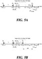
- FIGS. 5A and 5B are diagrams for illustrating a compromised-ECU identification method according to at least one exemplary embodiment of the present disclosure.
- the identification target ECU is a compromised ECU, that is, once the error generating unit 200 transitioned the compromised ECU to the bus-off state, following recovery of the compromised ECU from the bus-off state, the compromised ECU resumes the transmission of the attack CAN message at the retransmission time (t[m new ]) calculated by the calculation unit 230.
- the retransmission time t[m new ]
- the compromised ECU may be configured to transmit the attack CAN message on the CAN bus regardless of the retransmission time (t[m new ]) calculated by the calculation unit 230.
- the compromised-ECU identification unit 240 may be configured to determine whether the identification target ECU is a compromised ECU based on whether the attack CAN message is transmitted at the retransmission time (t[m new ]) calculated by the calculation unit 230. Specifically, the compromised-ECU identification unit 240 may be configured to identify the identification target ECU as being a compromised ECU by comparing the first attack CAN message transmission time (t[m i+1 ]) after the identification target ECU transitions to the bus-off state with the retransmission time (t [m new ]) calculated by the calculation unit 230.
- the compromised-ECU identification unit 240 may be configured to determine that the identification target ECU is a compromised ECU in the situation as shown in FIG. 5A where the first attack message transmission time (t[m i+1 ]) after the identification target ECU transitions to the bus-off state is within a preset threshold time from the retransmission time (t [m new ]). In other words, in response to determining that a difference, denoted as diff in FIG.
- the compromised-ECU identification unit 240 may be configured to determine that the identification target ECU is a compromised ECU.
- the compromised-ECU identification unit 240 may be configured to determine that the identification target ECU is not a compromised ECU in the situation as shown in FIG. 5B where a difference, denoted as diff in FIG. 5B , between the first attack CAN message transmission time (t[m i+1 ]) after the identification target ECU transitions to the bus-off state and the retransmission time (t [m new ]) calculated by the calculation unit 230 is greater than the preset threshold time.
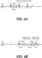
- FIGS. 6A and 6B are diagrams for illustrating a compromised-ECU identification method according to another exemplary embodiment of the present disclosure.
- the identification target ECU is a compromised ECU, that is, once the error generating unit 200 transitioned the compromised ECU to the bus-off state
- the compromised ECU does not transmit the attack CAN message on the CAN bus until the compromised ECU recovers from the bus-off state.
- the compromised ECU may be configured to transmit an attack CAN message on the CAN bus irrespective of the recovery of the identification target ECU.
- the attack CAN message may be transmitted more than once on the CAN bus before the identification target ECU recovers from the bus-off state.
- the compromised-ECU identification unit 240 may be configured to determine whether the identification target ECU is a compromised ECU based on whether the attack CAN message is transmitted before the recovery time (t[r']) calculated by the calculation unit 230. Specifically, in response to determining that the first attack CAN message transmission time (t[m i+1 ]) after the identification target ECU transitions to the bus-off state precedes the recovery time (t[r']), the compromised-ECU identification unit 240 may be configured to determine that the identification target ECU is not a compromised ECU.
- the error generating unit 200 prevent the transmission of the CAN message by the identification target ECU for a period greater than the transmission period of the attack CAN message by repeatedly transitioning the identification target ECU to the bus-off state for a certain time or longer and/or a certain number of times or more.
- the compromised-ECU identification unit 240 may take this opportunity while the identification target ECU is in the bus-off state to identify whether the identification target ECU is a compromised ECU according to detection or non-detection of an attack CAN message on the CAN bus.
- the compromised-ECU identification unit 240 may be configured to transmit control information for causing the error generating unit 200 and the calculation unit 230 to perform the compromised-ECU identification process for other ECUs.
- FIG. 7 is a flowchart of a method of transitioning an ECU to a bus-off state according to at least one exemplary embodiment of the present disclosure.
- the ECU identification apparatus 120 may be configured to transmit a diagnosis request message corresponding to the target ECU on the CAN bus (S700).
- the target ECU refers to an analysis target ECU to transition to a bus-off state for parameter analysis, or an identification target ECU to transition to a bus-off state to check whether that ECU is a compromised ECU.
- the ECU identification apparatus 120 may be configured to monitor the CAN bus (S710) and detect the initiation of transmission of the diagnosis response message by the target ECU (S720).
- the ECU identification apparatus 120 may be configured to detect the diagnosis response ID corresponding to the target ECU on the CAN bus and thereby detect the initiation of transmission of the diagnosis response message by the target ECU.
- the ECU identification apparatus 120 may be configured to transmit a plurality of dominant bits to the CAN bus in response to the detection of the initiation of transmission of the diagnosis response message (S730). For example, the ECU identification apparatus 120 may be configured to transmit six consecutive dominant bits on the CAN bus. Accordingly, the target ECU may be configured to detect a bit error.
- the ECU identification apparatus 120 may be configured to monitor the CAN bus (S710) and re-detect the initiation of transmission of the diagnosis response message by the target ECU (S720).
- the ECU identification apparatus 120 may be configured to transmit a plurality of dominant bits to the CAN bus in response to the re-detection of the initiation of transmission of the diagnosis response message (S730).
- the ECU identification apparatus 120 repeats Steps S710 to S730 until the target ECU transitions to the bus-off state where it can no longer transmit the diagnosis response message. Responsive to no more detection of the initiation of transmission of the diagnosis response message by the target ECU, the ECU identification apparatus 120 may be configured to determine that the target ECU has transitioned to the bus-off state (S740).
- FIG. 8 is a flowchart of a recovery parameter analysis method according to at least one exemplary embodiment of the present disclosure.
- the ECU identification apparatus 120 may be configured to monitor the CAN bus and obtains the ID of an ordinary CAN message transmitted by the analysis target ECU and the period of the ordinary CAN message (S800).
- the ECU identification apparatus 120 may be configured to transition the analysis target ECU to a bus-off state (S810).
- the ECU identification apparatus 120 may be configured to monitor the CAN bus to receive the ordinary CAN message that is resumed to be transmitted following the recovery of the analysis target ECU from the bus-off state. As the analysis target ECU recovers from the bus-off state, the ECU identification apparatus 120 may be configured to receive an ordinary CAN message again (S820).
- the ECU identification apparatus 120 may be configured to analyze the recovery parameters of the analysis target ECU (S830). For example, the ECU identification apparatus 120 may be configured to analyze the recovery parameters including a Wait Time, a Controller Recovery Type, and a Timer Behavior of the analysis target ECU based on at least one of the time when the analysis target ECU last transmitted the CAN message before it transitioned to the bus-off state, the time when the analysis target ECU transmitted the first CAN message after recovery from the bus-off state, and the time when the analysis target ECU transitioned to the bus-off state.
- the ECU identification apparatus 120 may be configured to store the analyzed recovery parameters (S840).
- the ECU identification apparatus 120 may be configured to nontransiently store the recovery parameters by associating them with the analysis target ECU.
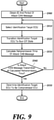
- FIG. 9 is a flowchart of a compromised-ECU identification method according to at least one exemplary embodiment of the present disclosure.
- the ECU identification apparatus 120 may be configured to obtain the ID of the attack CAN message and the transmission period of the attack CAN message (S900).
- the ECU identification apparatus 120 in response to the IDS 110 detecting an attack, may be configured to receive identification initiation information, including the ID of the attack CAN message and the transmission period of the attack CAN message, from the IDS 110.
- the ECU identification apparatus 120 in response to the IDS 110 detecting an attack, may be configured to receive the identification initiation information from the IDS 110 and thereafter directly monitor the CAN bus to obtain the ID and the transmission period of the attack CAN message.
- the ECU identification apparatus 120 may be configured to select an identification target ECU for a compromised-ECU identification (S910).
- the ECU identification apparatus 120 may be configured to select an identification target ECU by selecting one of the pre-stored diagnosis request IDs.
- the ECU identification apparatus 120 may be configured to transition the identification target ECU to the bus-off state (S920).
- the ECU identification apparatus 120 may be configured to calculate the retransmission time of the attack CAN message (S930). In other words, the ECU identification apparatus 120 may be configured to assume that the identification target ECU is a compromised ECU that transmits an attack CAN message and calculate a time at which the identification target ECU recovers from the bus-off state and resume transmission of the attack CAN message. The ECU identification apparatus 120 may be configured to calculate the retransmission time of the attack CAN message by using the recovery parameters mapped with the diagnosis request ID.
- the ECU identification apparatus 120 may be configured to check whether an attack CAN message is transmitted at the calculated retransmission time (S940). In response to determining that an attack CAN message is transmitted before and/or after a preset threshold time from the calculated retransmission time, the ECU identification apparatus 120 may be configured to determine that the identification target ECU is not a compromised ECU and selects another ECU as the identification target ECU. On the other hand, in response to determining that the attack CAN message is transmitted at a time within the preset threshold time from the calculated retransmission time, the ECU identification apparatus 120 may be configured to determine the identification target ECU to be a compromised ECU (S950).
- FIG. 10 is a flowchart of a compromised-ECU identification method according to another exemplary embodiment of the present disclosure.
- Steps S1000 to S1020 correspond to Steps S900 to S920 of FIG. 9 described above, detailed descriptions thereof will be omitted.
- the ECU identification apparatus 120 may be configured to obtain the ID of the attack CAN message and the transmission period of the attack CAN message (S 1000).
- the ECU identification apparatus 120 may be configured to select an identification target ECU for a compromised-ECU identification (S1010).
- the ECU identification apparatus 120 may be configured to select an identification target ECU by selecting one of the pre-stored diagnosis request IDs.
- the ECU identification apparatus 120 may be configured to transition the identification target ECU to the bus-off state (S 1020).
- the ECU identification apparatus 120 may be configured to calculate a recovery time when the identification target ECU is to recover from the bus-off state (S 1030).
- the ECU identification apparatus 120 may be configured to calculate the recovery time by using the recovery parameters mapped with the diagnosis request ID.
- the ECU identification apparatus 120 may be configured to check whether the attack CAN message is transmitted before the calculated recovery time (S 1040). In response to determining that the attack CAN message is transmitted before the calculated recovery time, the ECU identification apparatus 120 may be configured to determine that the identification target ECU is not a compromised ECU and select another ECU as the identification target ECU. On the other hand, in response to determining that no attack CAN message is transmitted before the calculated recovery time, the ECU identification apparatus 120 may be configured to determine the identification target ECU to be a compromised ECU (S 1050).
- FIGS. 7 to 10 are described to be sequentially performed, they merely instantiate the technical idea of some exemplary embodiments of the present disclosure. Therefore, a person having ordinary skill in the pertinent art could incorporate various modifications, additions, and substitutions in practicing the present disclosure by changing the sequence described by FIGS. 7 to 10 or by performing one or more of the steps in FIGS. 7 to 10 in parallel, without departing from the gist and nature of at least one embodiment of the present disclosure, and hence the steps in FIGS. 7 to 10 are not limited to the illustrated chronological sequences.
- Various implementations of the system and techniques described herein may be realized by digital electronic circuitry, integrated circuits, field-programmable gate arrays (FPGAs), application-specific integrated circuits (ASICs), computer hardware, firmware, software, and/or their combinations. These various implementations can include those realized in one or more computer programs executable on a programmable system.
- the programmable system includes at least one programmable processor coupled to receive and transmit data and instructions from and to a storage system, at least one input device, and at least one output device, wherein the programmable processor may be a special-purpose processor or a general-purpose processor.
- Computer programs which are also known as programs, software, software applications, or code, contain instructions for a programmable processor and are stored in a "computer-readable recording medium.”
- the non-transitory computer-readable recording medium includes any type of recording device on which data that can be read by a computer system are recordable.
- Examples of the non-transitory computer-readable recording medium include non-transitory media such as a ROM, CD-ROM, magnetic tape, floppy disk, memory card, hard disk, optical/magnetic disk, storage devices, and the like and transitory medium such as a carrier wave (e.g., transmission through the Internet) and data transmission medium.
- the non-transitory computer-readable recording medium may be distributed in computer systems connected via a network, wherein the computer-readable codes can be stored and executed in a distributed mode.
- the computer includes a programmable processor, a data storage system (including volatile memory, nonvolatile memory, or any other type of storage system or a combination thereof), and at least one communication interface.
- the programmable computer may be one of a server, a network device, a set-top box, an embedded device, a computer expansion module, a personal computer, a laptop, a personal data assistant (PDA), a cloud computing system, and a mobile device.
- PDA personal data assistant
- the CAN protocol's fault confinement mechanisms can be used to identify the ECU performing an attack on the CAN internal network. Therefore, obviating the need for changing the existing CAN protocol, the identification methods and apparatuses of the present disclosure can be applied to currently commercialized vehicles.
- the way of identifying a compromised controller achieves high scalability over the vehicle lines having the common CAN network configurations and ECUs supposed to follow their common recovery policies.
Landscapes
- Engineering & Computer Science (AREA)
- Computer Security & Cryptography (AREA)
- Computer Hardware Design (AREA)
- General Engineering & Computer Science (AREA)
- Computer Networks & Wireless Communication (AREA)
- Signal Processing (AREA)
- Theoretical Computer Science (AREA)
- Software Systems (AREA)
- General Physics & Mathematics (AREA)
- Physics & Mathematics (AREA)
- Computing Systems (AREA)
- Health & Medical Sciences (AREA)
- General Health & Medical Sciences (AREA)
- Virology (AREA)
- Small-Scale Networks (AREA)
- Automation & Control Theory (AREA)
Abstract
Description
- The present disclosure relates to identifying a compromised controller in an in-vehicle network.
- The statements in this section merely provide background information related to the present disclosure and do not necessarily constitute prior art. Providing vehicles with more and more software modules and external interfaces invites new attacks and vulnerability around in-vehicle networks. To detect or prevent vehicle cyber-attacks, various types of security solutions are proposed for in-vehicle networks, and focused researches have been actively conducted on an Intrusion Detection System (IDS) for detecting attacks across Controller Area Network (CAN) which are used as de facto standards for in-vehicle networks.
- In one type of spoofing attack, an attacker takes control of one of the Electronic Control Units (ECUs) and can use a counterfeited or compromised ECU to pretend to be another one of the ECUs by broadcasting messages seemingly generated by the another one of the ECUs over the network. Once IDS detects a CAN security attack, to get a restoration, for example, to have the normal patch or update of the compromised ECU used in the spoofing attack is premised on the identification of the compromised ECU.
- Developed related art includes a technology for identifying an ECU by using the characteristics of a power signal flowing through a CAN bus when the ECU transmits a message. This technology requires additional high-performance hardware to measure the power signal and susceptible to the vulnerability of the power signal as being sensitive to changes in external elements such as temperature, electromagnetic field, and model year.
- Additional related art discloses a technology for identifying an ECU by using physical properties of the ECU, such as the clock skew of a CAN message transmitted on a CAN bus. This technique is difficult to accurately identify the compromised ECU when it emulates the clock skew of another ECU. The year 2016 saw a report of a bus-off attack as a new Denial of Service (DoS) attack on the CAN bus. In a bus-off attack, the attacker uses the CAN protocol's fault confinement mechanisms to transition the target ECU to a bus-off state, making it impossible to send and receive messages.
- According to at least one aspect, the present disclosure provides a method, performed by an electronic device (120) in a controller area network, CAN, for identifying a compromised electronic control unit, ECU, that transmits an attack message on a CAN bus in a periodic transmission cycle, including in response to detecting the attack message, transitioning a first ECU among a plurality of ECUs connected to the CAN bus to a bus-off state intentionally, and determining whether the first ECU is the compromised ECU based at least in part on a time, which is predicted from recovery parameters related to the first ECU, for when the first ECU resumes a transmission of a CAN message and a time when the attack message is redetected on the CAN bus.
- The transitioning to the bus-off state may include transmitting a diagnosis request message corresponding to the first ECU, monitoring the CAN bus to detect an initiation of transmission of a diagnosis response message by the first ECU, and in response to detecting the initiation of transmission of the diagnosis response message, causing a transmission error in the diagnosis response message by transmitting a plurality of dominant bits to the CAN bus until the first ECU transitions to the bus-off state.
- The determining whether the first ECU is the compromised ECU may include predicting, as a predicted transmission resumption time, the time for when the first ECU resumes the transmission of the CAN message by using the recovery parameters related to the first ECU, and determining that the first ECU is the compromised ECU in response to determining that a difference between the predicted transmission resumption time and the time when the attack message is redetected on the CAN bus is less than or equal to a preset threshold time.
- The method may further include in response to determining that the difference between the predicted transmission resumption time and the time when the attack message is redetected on the CAN bus is greater than the preset threshold time, transitioning a second ECU different from the first ECU to a bus-off state intentionally, and determining whether the second ECU is the compromised ECU based at least in part on a time, which is predicted from recovery parameters related to the second ECU, for when the second ECU resumes a transmission of a CAN message and a time when the attack message is redetected on the CAN bus.
- The determining whether the first ECU is the compromised ECU may include calculating, as a calculated recovery time, a time for when the first ECU recovers from the bus-off state by using the recovery parameters related to the first ECU, and determining whether the first ECU is the compromised ECU based on whether the attack message is redetected on the CAN bus before the calculated recovery time.
- The transitioning of the first ECU to the bus-off state may include transitioning the first ECU to the bus-off state repeatedly to prevent the transmission of the CAN message by the first ECU for a period greater than the periodic transmission cycle of the attack message, and the determining whether the first ECU is the compromised ECU may include determining whether the first ECU is the compromised ECU based on whether the attack message is redetected on the CAN bus while the first ECU is in the bus-off state.
- According to another aspect, the present disclosure provides a method, performed by an electronic device in a controller area network, CAN, for analyzing recovery parameters related to a recovery of an electronic control unit, ECU, connected to a CAN bus, from a bus-off state, including transitioning the ECU that periodically transmits a controller area network message, CAN message, to the bus-off state intentionally, and monitoring the CAN bus to receive the CAN message that is resumed to be transmitted following the recovery of the ECU from the bus-off state, and analyzing the recovery parameters of the ECU based in part on a time when the CAN message is received.
- The transitioning of the ECU to the bus-off state may include transmitting a diagnosis request message corresponding to the ECU, monitoring the CAN bus to detect an initiation of transmission of a diagnosis response message by the ECU, and in response to detecting the initiation of transmission of the diagnosis response message, causing a transmission error in the diagnosis response message by transmitting a plurality of dominant bits to the CAN bus until the ECU transitions to the bus-off state.
- The analyzing the recovery parameters may include analyzing the recovery parameters, including a Wait Time, a Controller Recovery Type, and a Timer Behavior of the ECU based on at least one of a time when the ECU transmits a last CAN message before the ECU transitions to the bus-off state, a time when the ECU transitions to the bus-off state, and a time when the ECU transmits a first CAN message after the ECU recovers from the bus-off state.
- The method may further include storing the recovery parameters non-transiently.
- According to yet another aspect, the present disclosure provides an electronic device (120) for identifying a compromised electronic control unit, ECU, that transmits an attack message on a controller area network bus, CAN bus, in a periodic transmission cycle, the electronic device including an error generating unit (200) and a compromised-ECU identification unit (240). The error generating unit (200) is configured to, in response to detecting the attack message, transition a first ECU among a plurality of ECUs connected to the CAN bus to a bus-off state intentionally. The compromised-ECU identification unit (240) is configured to determine whether the first ECU is the compromised ECU based at least in part on a time, which is predicted from recovery parameters related to the first ECU, for when the first ECU resumes a transmission of a CAN message and a time when the attack message is redetected on the CAN bus.
- The error generating unit (200) may be configured to transmit a diagnosis request message corresponding to the first ECU, monitor the CAN bus to detect an initiation of transmission of a diagnosis response message by the first ECU, and in response to detecting the initiation of transmission of the diagnosis response message, cause a transmission error in the diagnosis response message by transmitting a plurality of dominant bits to the CAN bus until the first ECU transitions to the bus-off state.
- The compromised-ECU identification unit (240) may be configured to predict, as a predicted transmission resumption time, the time for when the first ECU resumes the transmission of the CAN message by using the recovery parameters related to the first ECU, and determine that the first ECU is the compromised ECU in response to determining that a difference between the predicted transmission resumption time and the time when the attack message is redetected on the CAN bus is less than or equal to a preset threshold time.
- The error generating unit (200) may be configured to, in response to determining that the difference between the predicted transmission resumption time and the time when the attack message is redetected on the CAN bus is greater than the preset threshold time, transition a second ECU different from the first ECU to a bus-off state intentionally, and the compromised-ECU identification unit (240) may be configured to determine whether the second ECU is the compromised ECU based at least in part on a time, which is predicted from recovery parameters related to the second ECU, for when the second ECU resumes a transmission of a CAN message and a time when the attack message is redetected on the CAN bus.
- The compromised-ECU identification unit (240) may be configured to calculate, as a calculated recovery time, a time for when the first ECU recovers from the bus-off state by using the recovery parameters related to the first ECU, and determine whether the first ECU is the compromised ECU based on whether the attack message is redetected on the CAN bus before the calculated recovery time.
- The error generating unit (200) may be configured to transition the first ECU to the bus-off state repeatedly to prevent the transmission of the CAN message by the first ECU for a period greater than the periodic transmission cycle of the attack message, and the compromised-ECU identification unit (240) may be configured to determine whether the first ECU is a compromised ECU based on whether the attack message is redetected on the CAN bus while the first ECU is in the bus-off state.
- According to yet another aspect, the present disclosure provides an electronic device for analyzing recovery parameters related to a recovery of an electronic control unit ,ECU, connected to a controller area network bus, CAN bus, from a bus-off state, the electronic device including an error generating unit (200) and a parameter analysis unit (210). The error generating unit (200) is configured to transition the ECU that periodically transmits a controller area network message, CAN message, to the bus-off state intentionally. The parameter analysis unit (210) is configured to monitor the CAN bus to receive the CAN message that is resumed to be transmitted following the recovery of the ECU from the bus-off state, and to analyze the recovery parameters of the ECU based in part on a time when the CAN message is received.
- The error generating unit (200) may be configured to transmit a diagnosis request message corresponding to the ECU, monitor the CAN bus to detect an initiation of transmission of a diagnosis response message by the ECU, and in response to detecting the initiation of transmission of the diagnosis response message for causing a transmission error in the diagnosis response message by transmitting a plurality of dominant bits to the CAN bus until the ECU transitions to the bus-off state.
- The parameter analysis unit (210) may be configured to analyze the recovery parameters, including a Wait Time, a Controller Recovery Type, and a Timer Behavior of the ECU, based on at least one of a time when the ECU transmits a last CAN message before the ECU transitions to the bus-off state, a time when the ECU transitions to the bus-off state, and a time when the ECU transmits a first CAN message after the ECU recovers from the bus-off state.
- The parameter analysis unit (210) may be configured to store the recovery parameters non-transiently by associating the recovery parameters with the ECU.
- The objects, features and advantages of the present disclosure will be more apparent from the following detailed description in conjunction with the accompanying drawings, in which:
-
FIG. 1 is a block diagram schematically showing a CAN (Controller Area Network) system according to at least one exemplary embodiment of the present disclosure. -
FIG. 2 is a block diagram schematically showing an ECU (Electronic Control Unit) identification apparatus according to at least one exemplary embodiment of the present disclosure. -
FIG. 3 is a diagram illustrating a method of transitioning an ECU to a bus-off state according to at least one exemplary embodiment of the present disclosure. -
FIGS. 4A to 4D are diagrams for illustrating recovery parameters according to at least one exemplary embodiment of the present disclosure. -
FIGS. 5A and 5B are diagrams for illustrating a compromised-ECU identification method according to at least one exemplary embodiment of the present disclosure. -
FIGS. 6A and 6B are diagrams for illustrating a compromised-ECU identification method according to another exemplary embodiment of the present disclosure. -
FIG. 7 is a flowchart of a method of transitioning an ECU to a bus-off state according to at least one exemplary embodiment of the present disclosure. -
FIG. 8 is a flowchart of a recovery parameter analysis method according to at least one exemplary embodiment of the present disclosure. -
FIG. 9 is a flowchart of a compromised-ECU identification method according to at least one exemplary embodiment of the present disclosure. -
FIG. 10 is a flowchart of a compromised-ECU identification method according to another exemplary embodiment of the present disclosure. -
- 10: CAN system
- 100 to 106: ECU
- 110: IDS
- 120: ECU identification apparatus
- 130: ECU update apparatus
- 200: error generating unit
- 210: parameter analysis unit
- 220: parameter storage unit
- 230: calculation unit
- 240: compromised-ECU identification unit
- It is understood that the term "vehicle" or "vehicular" or other similar term as used herein is inclusive of motor vehicles in general such as passenger automobiles including sports utility vehicles (SUV), buses, trucks, various commercial vehicles, watercraft including a variety of boats and ships, aircraft, and the like, and includes hybrid vehicles, electric vehicles, combustion, plug-in hybrid electric vehicles, hydrogen-powered vehicles and other alternative fuel vehicles (e.g. fuels derived from resources other than petroleum).
- Unless specifically stated or obvious from context, as used herein, the term "about" is understood as within a range of normal tolerance in the art, for example within 2 standard deviations of the mean. "About" can be understood as within 10%, 9%, 8%, 7%, 6%, 5%, 4%, 3%, 2%, 1%, 0.5%, 0.1%, 0.05%, or 0.01% of the stated value. Unless otherwise clear from the context, all numerical values provided herein are modified by the term "about."
- Some exemplary embodiments of the present disclosure provide methods and systems for identifying a compromised controller being used for an attack on a CAN network by using fault confinement mechanisms of the CAN protocol.
- Hereinafter, some exemplary embodiments of the present disclosure will be described in detail with reference to the accompanying drawings. In the following description, like reference numerals preferably designate like elements, although the elements are shown in different drawings. Further, in the following description of some embodiments, a detailed description of known functions and configurations incorporated therein will be omitted for the purpose of clarity and for brevity.
- Additionally, various terms such as first, second, A, B, (a), (b), etc., are used solely to differentiate one component from the other but not to imply or suggest the substances, order, or sequence of the components. Throughout this specification, when a part 'includes' or 'comprises' a component, the part is meant to further include other components, not to exclude thereof unless specifically stated to the contrary. The terms such as 'unit', 'module', and the like refer to one or more units for processing at least one function or operation, which may be implemented by hardware, software, or a combination thereof.
- Before describing various exemplary embodiments of the present disclosure, fault confinement mechanisms of the Controller Area Network Protocol (CAN protocol) will be discussed.
- Each ECU (Electronic Control Unit) connected on the CAN bus has a Transmit Error Count (TEC) and Receive Error Count (REC) that increase or decrease with a specific weight according to the success of message transmission or reception or occurrence of an error. The state of the ECU is defined based on TEC and REC. In particular, when the TEC is equal to or greater than 256, the ECU transitions to a state in which it cannot transmit and receive any messages on the CAN bus. This state is referred to as a bus-off state.
- On the other hand, the return of the ECU from the bus-off state back to the active state capable of participating in CAN communications is referred to as recovery. The ECU may recover from the bus-off state by monitoring 128 consecutive 11 recessive bits. In an actual operating environment, an additional time of tens to hundreds of milliseconds is required for each ECU.
- Based on such fault confinement mechanisms as above, some exemplary embodiments of the present disclosure provide a method and system for forcibly transitioning the ECU to the bus-off state and using the characteristics appearing in the recovery process to identify the ECU.
-
FIG. 1 is a block diagram schematically showing a CAN system according to at least one exemplary embodiment of the present disclosure. As shown inFIG. 1 , theCAN system 10 according to at least one exemplary embodiment may include all or some of at least one ofECUs 100 to 106, an Intrusion Detection System (IDS) 110, anECU identification apparatus 120, and anECU update apparatus 130. Not all blocks shown inFIG. 1 are essential components, and some blocks included in theCAN system 10 may be added, changed, or deleted in other exemplary embodiments. In other words, the example configuration ofFIG. 1 is illustrative of theCAN system 10 according to at least one exemplary embodiment with components for the function of identifying a compromised ECU, and it should be appreciated that theCAN system 10 may have configurations of more or fewer components or other components than those illustrated to implement other functions. TheECUs 100 to 106 are electronic devices having a CAN communication function and are configured to transmit an ordinary CAN message and/or an attack CAN message on a CAN bus in a periodic transmission cycle. - The
IDS 110 may be configured to detect an attack that occurred on the CAN bus. In response to detecting an attack on the CAN bus, theIDS 110 may be configured to transmit identification initiation information to theECU identification apparatus 120. In particular, the identification initiation information may include the IDentification (ID) of the attack CAN message and/or the transmission period of the attack CAN message. - The
ECU identification device 120 may be a separate electronic device accessible to the CAN bus, or may be included as a functional module in an electronic device implementing theIDS 110. TheECU identification apparatus 120 may be configured to analyze and store the recovery parameters corresponding to therespective ECUs 100 to 106, and identify the ECU using the recovery parameters. According to at least one exemplary embodiment of the present disclosure, theECU identification apparatus 120 may be configured to analyze and store recovery parameters corresponding to therespective ECUs 100 to 106 before theIDS 110 detects an attack. In response to theIDS 110 detecting an attack and transmitting the identification initiation information to theECU identification apparatus 120, the latter utilizes the recovery parameters to identify the compromised ECU that performs the attack. - Meanwhile, according to another exemplary embodiment of the present disclosure, the
ECU identification apparatus 120 may be configured to receive and store recovery parameters corresponding to therespective ECUs 100 to 106 from an externally connected ECU analysis apparatus (not shown). A detailed description of theECU identification apparatus 120 will be presented with reference toFIG. 2 . - The
ECU update apparatus 130 may be configured to restore the compromised ECU to a normal ECU by performing an update of the compromised ECU identified by theECU identification apparatus 120. the IDS or the ECU update apparatus in the present disclosure encompasses all IDSs or ECU update apparatus that may be easily employed by a person skilled in the art, and the IDS or the ECU update apparatus is not limited to having a specific configuration and/or function. -
FIG. 2 is a block diagram schematically showing an ECU identification apparatus according to at least one exemplary embodiment of the present disclosure. As shown inFIG. 2 , theECU identification apparatus 120 according to at least one exemplary embodiment may include all or some of anerror generating unit 200, aparameter analysis unit 210, aparameter storage unit 220, acalculation unit 230, and the compromised-ECU identification unit 240. Not all blocks shown inFIG. 2 are essential components, and some blocks included in theECU identification apparatus 120 may be added, changed, or deleted in other embodiments. For example, theECU identification apparatus 120 may not include theparameter analysis unit 210 if it receives recovery parameters from its interworked ECU analysis apparatus that is a separate stand-alone apparatus. In particular, the ECU analysis apparatus may include all or some of theerror generation unit 200 and theparameter analysis unit 210. Theerror generating unit 200 causes an error on the CAN bus to transition the ECU to the bus-off state. - According to at least one exemplary embodiment of the present disclosure, the
error generating unit 200 may transition the target ECU to a bus-off state using an ECU diagnosis protocol. In particular, the target ECU refers to an analysis target ECU for which recovery parameters are analyzed or an identification target ECU to be checked whether it is identified as a compromised ECU. -
FIG. 3 is a diagram illustrating a method of transitioning an ECU to a bus-off state according to at least one exemplary embodiment of the present disclosure. In the CAN system, a diagnosis request ID and a diagnosis response ID are defined, corresponding to each ECU. For example, a diagnosis request ID and a diagnosis response ID may be defined in a range of 0x700 or more. InFIG. 3 , DQ_IDN and DR_IDN respectively denote a diagnosis request ID and a diagnosis response ID corresponding to the target ECU transmitting an CAN message on a CAN bus in a periodic transmission cycle. Additionally, IDN and T respectively denote the ID and the period of the CAN message. As shown inFIG. 3 , in response to theerror generating unit 200 transmitting on a CAN bus a diagnosis request message including a diagnosis request ID (DQ_IDN), the target ECU may be configured to transmit on the CAN bus a diagnosis response message including a diagnosis response ID (DR_IDN). - The
error generating unit 200 according to at least one exemplary embodiment may be configured to transmit the diagnosis request message corresponding to the target ECU, monitor the CAN bus to detect the initiation of transmission of the diagnosis response message by the target ECU, and in response to a detection of the initiation of transmission of the diagnosis response message by the target ECU, transmit a plurality of dominant bits on the CAN bus, causing a transmission error to occur in the diagnosis response message of the target ECU. For example, theerror generating unit 200 is responsive to a detection of the diagnosis response ID corresponding to the target ECU, for transmitting six consecutive dominant bits on the CAN bus. Accordingly, the target ECU may be configured to detect a bit error, and the target ECU fails to transmit a diagnosis response message. The target ECU may be configured to transmit the error frame message on the CAN bus, increase the TEC (Transmit Error Count) and retransmit the diagnosis response message. - The
error generating unit 200 according to at least one exemplary embodiment is responsive to a detection of the retransmitted diagnosis response ID, for retransmitting a plurality of dominant bits on the CAN bus. Theerror generating unit 200 may be configured to monitor the CAN bus to detect the transmission of an error frame message and the initiation of transmission of a diagnosis response message of the target ECU. Theerror generating unit 200 may be configured to transmit a plurality of dominant bits on the CAN bus in response to detecting the initiation of transmission of the diagnosis response message of the target ECU, thereby increasing the TEC of the target ECU to transition the target ECU to the bus-off state. - The
error generating unit 200 may be configured to determine the time (t[en]) at which the last error frame message is transmitted on the CAN bus as the time at which the target ECU transitions to the bus-off state. On the other hand, theerror generating unit 200 using the above-described ECU diagnosis protocol is merely one exemplary embodiment of the technique for transitioning the target ECU to the bus-off state, and as long as a technique may be employed in other exemplary embodiments of the present disclosure by those skilled in this art for transitioning the target ECU to the bus-off state, it may be used in place of theerror generating unit 200. - The
parameter analysis unit 210 may be configured to analyze recovery parameters related to the inherent characteristics of the analysis target ECU when the latter recovers from the bus-off state. Specifically, theparameter analysis unit 210 may be configured to monitor the CAN bus to receive the CAN message that is resumed to be transmitted following the recovery of the analysis target ECU from the bus-off state, and to analyze the recovery parameters of the analysis target ECU based in part on a time when the CAN message is received. - Hereinafter, before describing the method of the
parameter analysis unit 210 analyzing recovery parameters, the recovery parameters defined in some exemplary embodiments of the present disclosure will be described.FIGS. 4A to 4D are diagrams for illustrating the recovery parameters according to at least one exemplary embodiment of the present disclosure. In the present disclosure, three recovery parameters of a Wait Time, a Controller Recovery Type, and a Timer Behavior are defined to analyze inherent characteristics that appear in the ECU in the process of resuming CAN message transmission after recovery from the bus-off state. - In
FIGS. 4A to 4D , t[mi] denotes the time when the ECU transmits the last CAN message before it transitions to the bus-off state, t[en] denotes the time when the ECU transitions to a bus-off state, t[r] denotes the time when the ECU recovers from the bus-off state, and t[mi+1] denotes the time when the ECU transmits the first CAN message after it recovers from the bus-off state. As shown inFIG. 4A , d+r denotes the difference between t[r] and t[en]. Herein d is Wait Time and r is a variable representing Controller Recovery Type. - Wait Time is a waiting time for the ECU to perform recovery after detecting that it has transitioned to the bus-off state. Wait Time may be set to a specific time or a specific number of interruptions. For example, the ECU may be configured to perform recovery after waiting for about 60 to 70 ms after detecting the bus-off state. Alternatively, the ECU may be configured to perform recovery after waiting for 7 interruptions from the time when it last transmitted the CAN message before transitioning to the bus-off state.
- Controller Recovery Type is a parameter that defines the time at which the CAN controller inside the ECU monitors 128 consecutive 11 recessive bits to perform recovery, and it is classified as Immediate recovery or Wait-then-recovery. When Controller Recovery Type is Immediate recovery, r has a value of 0 (zero), and when Controller Recovery Type is Wait-then-recovery, r has a value greater than 0.
- When Controller Recovery Type is Immediate recovery, the CAN controller may be configured to monitor 128 consecutive 11 recessive bits immediately upon detection of a bus-off state. In other words, the CAN controller may be configured to monitor during Wait Time and perform recovery immediately after Wait Time. On the other hand, when Controller Recovery Type is Wait-then-recovery, the CAN controller may be configured to first wait for Wait Time, monitor 128 consecutive 11 recessive bits, and perform recovery.
- Timer Behavior is a parameter that defines how an ECU internal timer, which is provided for periodically transmitting CAN messages, operates during a bus-off state and recovery, and it is classified into Initialized Timer, Suspended Timer, and Alive Timer.
- As shown in
FIG. 4B , when Timer Behavior is an Initialized Timer, the ECU may be configured to initialize the timer as it recovers from the bus-off state. As a result, a message transmission interrupt occurs and the ECU resumes CAN message transmission immediately after recovery regardless of the CAN message transmission period. - As shown in
FIG. 4C , when Timer Behavior is a Suspended Timer, the ECU may be configured to stop the timer as it detects a bus-off state, and count the timer again after recovery. The timer may be stopped before the ECU recovers from the bus-off state, so no message transmission interrupt occurs. - As shown in
FIG. 4D , when Timer Behavior is Alive Timer, the timer operates regardless of bus-off transition and recovery of the ECU and generates a message transmission interrupt in the same manner as in a normal state. The ECU may be configured to ignore the message transmission interrupt that occurs when it is in the bus-off state. - The
parameter analysis unit 210 according to at least one exemplary embodiment of the present disclosure may be configured to analyze Wait Time and Controller Recovery Type of the analysis target ECU based on the time (t[mi+1]) at which the analysis target ECU resumes transmission of an ordinary CAN message and the time (t[en]) at which the analysis target ECU transitions to a bus-off state. - Specifically, the
parameter analysis unit 210 may be configured to analyze Wait Time and Controller Recovery Type of the analysis target ECU by using time-1 (t[mi+1]-t[en]) and time-2 (t[mi+1]-t[en]-taR) wherein time-1 is the difference between the time (t[mi+1]) at which the analysis target ECU resumes transmission of the ordinary CAN message and the time (t[en]) at which the analysis target ECU transitions to the bus-off state, and time-2 equals to time-1 (t[mi+1]-t[en]) minus the time (tAR) taken for monitoring 128 consecutive 11 bits. - The
parameter analysis unit 210 may be configured to monitor a plurality of analysis units each being defined by a set of bus-off, recovery, and message retransmission of the analysis target ECU. Theparameter analysis unit 210 may be configured to calculate time-1 and time-2 based on t[en], t[mi+1], and tAR measured for each analysis unit. Theparameter analysis unit 210 may be configured to determine Wait Time and Controller Recovery Type of the analysis target ECU by comparing the distribution of time-1 values and the distribution of time-2 values. For example, in response to determining that the variance (or standard deviation, hereinafter the same) of time-1 values is less than the variance of time-2 values, theparameter analysis unit 210 may be configured to determine that Controller Recovery Type is Immediate recovery. On the other hand, in response to determining that the variance of time-1 values is greater than the variance of time-2 values, theparameter analysis unit 210 may be configured to determine that Controller Recovery Type is Wait-then-recovery. Additionally, theparameter analysis unit 210 may be configured to determine an average of values having a smaller variance among time-1 and time-2 values as the Wait Time. - The
parameter analysis unit 210 according to at least one exemplary embodiment may find out Timer Behavior of the analysis target ECU using the CAN message transmission period (T) and the CAN message transmission interval (B) before and after bus off. Table 1 shows Timer Behavior according to the relationship between the CAN message transmission period (T) and the CAN message transmission interval (B) before and after bus-off.Table 1 Relationship between T and B Timer Behavior d + r ≤ B ≤ T + d + r Initialized B = T + d + r Suspended B = n·T, (n=Natural Number) Alive - The
parameter analysis unit 210 may be configured to map the analyzed recovery parameter with the diagnosis request ID and the diagnosis response ID of the analysis target ECU and store the mapping results in theparameter storage unit 220. - The
calculation unit 230 may be configured to calculate a time for the identification of the compromised ECU by using the recovery parameters stored in theparameter storage unit 220. - According to at least one exemplary embodiment of the present disclosure, the
calculation unit 230 calculates a retransmission time when to resume the transmission of the attack CAN message. In other words, assuming that the identification target ECU is a compromised ECU that transmits an attack CAN message, thecalculation unit 230 may be configured to calculate a time at which the identification target ECU recovers from the bus-off state and resume transmission of the attack CAN message. Thecalculation unit 230 may be configured to calculate the retransmission time (t[mnew]) by using at least one of the time (t[en]) when the identification target ECU transitioned to the bus-off state, the time (t[mi]) when the last attack CAN message transmitted before the identification target ECU transitioned to the bus-off state, and the recovery parameters. - Table 2 shows the calculated retransmission time (t[mnew]) according to Timer Behavior of the identification target ECU.
Table 2 Timer Behavior t[mnew] Initialized t[mnew] = t[en] + d + r Suspended t[mnew] = t[mi] + T + d + r Alive t[mnew] = t[mi] + n·T, (t[mi] + n·T > t[r]) - According to another exemplary embodiment of the present disclosure, the
calculation unit 230 calculates a recovery time at which the identification target ECU recovers from the bus-off state. For example, as shown inFIG. 4A , thecalculation unit 230 may be configured to calculate the recovery time by using the time (t[en]) at which the identification target ECU transitions to the bus-off state, Wait Time, and Controller Recovery Type. - The compromised-
ECU identification unit 240 uses may be configured to use at least one of the retransmission time and the recovery time, which are calculated by thecalculation unit 230, and the first attack CAN message transmission time (t[mi+1]) after the identification target ECU transitions to the bus-off state to determine whether the identification target ECU is a compromised ECU. -
FIGS. 5A and 5B are diagrams for illustrating a compromised-ECU identification method according to at least one exemplary embodiment of the present disclosure. As shown inFIG. 5A , if the identification target ECU is a compromised ECU, that is, once theerror generating unit 200 transitioned the compromised ECU to the bus-off state, following recovery of the compromised ECU from the bus-off state, the compromised ECU resumes the transmission of the attack CAN message at the retransmission time (t[mnew]) calculated by thecalculation unit 230. On the other hand, as shown inFIG. 5B , if the identification target ECU is not a compromised ECU, that is, once theerror generating unit 200 transitioned an ECU other than the compromised ECU to the bus-off state, the compromised ECU may be configured to transmit the attack CAN message on the CAN bus regardless of the retransmission time (t[mnew]) calculated by thecalculation unit 230. - On this account, the compromised-
ECU identification unit 240 according to at least one exemplary embodiment may be configured to determine whether the identification target ECU is a compromised ECU based on whether the attack CAN message is transmitted at the retransmission time (t[mnew]) calculated by thecalculation unit 230. Specifically, the compromised-ECU identification unit 240 may be configured to identify the identification target ECU as being a compromised ECU by comparing the first attack CAN message transmission time (t[mi+1]) after the identification target ECU transitions to the bus-off state with the retransmission time (t [mnew]) calculated by thecalculation unit 230. - The compromised-
ECU identification unit 240 may be configured to determine that the identification target ECU is a compromised ECU in the situation as shown inFIG. 5A where the first attack message transmission time (t[mi+1]) after the identification target ECU transitions to the bus-off state is within a preset threshold time from the retransmission time (t [mnew]). In other words, in response to determining that a difference, denoted as diff inFIG. 5A , between the first attack CAN message transmission time (t[mi+1]) after the identification target ECU transitions to the bus-off state and the retransmission time (t [mnew]) calculated by thecalculation unit 230 is less than or equal to the preset threshold time, the compromised-ECU identification unit 240 may be configured to determine that the identification target ECU is a compromised ECU. - On the other hand, the compromised-
ECU identification unit 240 may be configured to determine that the identification target ECU is not a compromised ECU in the situation as shown inFIG. 5B where a difference, denoted as diff inFIG. 5B , between the first attack CAN message transmission time (t[mi+1]) after the identification target ECU transitions to the bus-off state and the retransmission time (t [mnew]) calculated by thecalculation unit 230 is greater than the preset threshold time. -
FIGS. 6A and 6B are diagrams for illustrating a compromised-ECU identification method according to another exemplary embodiment of the present disclosure. if the identification target ECU is a compromised ECU, that is, once theerror generating unit 200 transitioned the compromised ECU to the bus-off state, the compromised ECU does not transmit the attack CAN message on the CAN bus until the compromised ECU recovers from the bus-off state. On the other hand, as shown inFIG. 6A , if the identification target ECU is not a compromised ECU, that is, once theerror generating unit 200 transitioned an ECU other than the compromised ECU to a bus-off state, the compromised ECU may be configured to transmit an attack CAN message on the CAN bus irrespective of the recovery of the identification target ECU. In a particular case of an attack CAN message being injected onto the CAN bus at a fast cycle, the attack CAN message may be transmitted more than once on the CAN bus before the identification target ECU recovers from the bus-off state. - On this account, the compromised-
ECU identification unit 240 according to another exemplary embodiment may be configured to determine whether the identification target ECU is a compromised ECU based on whether the attack CAN message is transmitted before the recovery time (t[r']) calculated by thecalculation unit 230. Specifically, in response to determining that the first attack CAN message transmission time (t[mi+1]) after the identification target ECU transitions to the bus-off state precedes the recovery time (t[r']), the compromised-ECU identification unit 240 may be configured to determine that the identification target ECU is not a compromised ECU. - As shown in
FIG. 6B ,according to another exemplary embodiment of the present disclosure, to identify a compromised ECU that transmits an attack CAN message at a period longer than the Wait Time of the identification target ECU or to increase the reliability of identification of the compromised-ECU, theerror generating unit 200 prevent the transmission of the CAN message by the identification target ECU for a period greater than the transmission period of the attack CAN message by repeatedly transitioning the identification target ECU to the bus-off state for a certain time or longer and/or a certain number of times or more. Then, the compromised-ECU identification unit 240 may take this opportunity while the identification target ECU is in the bus-off state to identify whether the identification target ECU is a compromised ECU according to detection or non-detection of an attack CAN message on the CAN bus. - According to at least one exemplary embodiment of the present disclosure, in response to determining that the identification target ECU is not a compromised ECU, the compromised-
ECU identification unit 240 may be configured to transmit control information for causing theerror generating unit 200 and thecalculation unit 230 to perform the compromised-ECU identification process for other ECUs. -
FIG. 7 is a flowchart of a method of transitioning an ECU to a bus-off state according to at least one exemplary embodiment of the present disclosure. TheECU identification apparatus 120 may be configured to transmit a diagnosis request message corresponding to the target ECU on the CAN bus (S700). In particular, the target ECU refers to an analysis target ECU to transition to a bus-off state for parameter analysis, or an identification target ECU to transition to a bus-off state to check whether that ECU is a compromised ECU. - The
ECU identification apparatus 120 may be configured to monitor the CAN bus (S710) and detect the initiation of transmission of the diagnosis response message by the target ECU (S720). TheECU identification apparatus 120 may be configured to detect the diagnosis response ID corresponding to the target ECU on the CAN bus and thereby detect the initiation of transmission of the diagnosis response message by the target ECU. TheECU identification apparatus 120 may be configured to transmit a plurality of dominant bits to the CAN bus in response to the detection of the initiation of transmission of the diagnosis response message (S730). For example, theECU identification apparatus 120 may be configured to transmit six consecutive dominant bits on the CAN bus. Accordingly, the target ECU may be configured to detect a bit error. - The
ECU identification apparatus 120 may be configured to monitor the CAN bus (S710) and re-detect the initiation of transmission of the diagnosis response message by the target ECU (S720). TheECU identification apparatus 120 may be configured to transmit a plurality of dominant bits to the CAN bus in response to the re-detection of the initiation of transmission of the diagnosis response message (S730). TheECU identification apparatus 120 repeats Steps S710 to S730 until the target ECU transitions to the bus-off state where it can no longer transmit the diagnosis response message. Responsive to no more detection of the initiation of transmission of the diagnosis response message by the target ECU, theECU identification apparatus 120 may be configured to determine that the target ECU has transitioned to the bus-off state (S740). -
FIG. 8 is a flowchart of a recovery parameter analysis method according to at least one exemplary embodiment of the present disclosure. TheECU identification apparatus 120 may be configured to monitor the CAN bus and obtains the ID of an ordinary CAN message transmitted by the analysis target ECU and the period of the ordinary CAN message (S800). TheECU identification apparatus 120 may be configured to transition the analysis target ECU to a bus-off state (S810). TheECU identification apparatus 120 may be configured to monitor the CAN bus to receive the ordinary CAN message that is resumed to be transmitted following the recovery of the analysis target ECU from the bus-off state. As the analysis target ECU recovers from the bus-off state, theECU identification apparatus 120 may be configured to receive an ordinary CAN message again (S820). - The
ECU identification apparatus 120 may be configured to analyze the recovery parameters of the analysis target ECU (S830). For example, theECU identification apparatus 120 may be configured to analyze the recovery parameters including a Wait Time, a Controller Recovery Type, and a Timer Behavior of the analysis target ECU based on at least one of the time when the analysis target ECU last transmitted the CAN message before it transitioned to the bus-off state, the time when the analysis target ECU transmitted the first CAN message after recovery from the bus-off state, and the time when the analysis target ECU transitioned to the bus-off state. TheECU identification apparatus 120 may be configured to store the analyzed recovery parameters (S840). TheECU identification apparatus 120 may be configured to nontransiently store the recovery parameters by associating them with the analysis target ECU. -
FIG. 9 is a flowchart of a compromised-ECU identification method according to at least one exemplary embodiment of the present disclosure. TheECU identification apparatus 120 may be configured to obtain the ID of the attack CAN message and the transmission period of the attack CAN message (S900). According to at least one exemplary embodiment of the present disclosure, in response to theIDS 110 detecting an attack, theECU identification apparatus 120 may be configured to receive identification initiation information, including the ID of the attack CAN message and the transmission period of the attack CAN message, from theIDS 110. According to another exemplary embodiment of the present disclosure, in response to theIDS 110 detecting an attack, theECU identification apparatus 120 may be configured to receive the identification initiation information from theIDS 110 and thereafter directly monitor the CAN bus to obtain the ID and the transmission period of the attack CAN message. - The
ECU identification apparatus 120 may be configured to select an identification target ECU for a compromised-ECU identification (S910). TheECU identification apparatus 120 may be configured to select an identification target ECU by selecting one of the pre-stored diagnosis request IDs. TheECU identification apparatus 120 may be configured to transition the identification target ECU to the bus-off state (S920). - The
ECU identification apparatus 120 may be configured to calculate the retransmission time of the attack CAN message (S930). In other words, theECU identification apparatus 120 may be configured to assume that the identification target ECU is a compromised ECU that transmits an attack CAN message and calculate a time at which the identification target ECU recovers from the bus-off state and resume transmission of the attack CAN message. TheECU identification apparatus 120 may be configured to calculate the retransmission time of the attack CAN message by using the recovery parameters mapped with the diagnosis request ID. - The
ECU identification apparatus 120 may be configured to check whether an attack CAN message is transmitted at the calculated retransmission time (S940). In response to determining that an attack CAN message is transmitted before and/or after a preset threshold time from the calculated retransmission time, theECU identification apparatus 120 may be configured to determine that the identification target ECU is not a compromised ECU and selects another ECU as the identification target ECU. On the other hand, in response to determining that the attack CAN message is transmitted at a time within the preset threshold time from the calculated retransmission time, theECU identification apparatus 120 may be configured to determine the identification target ECU to be a compromised ECU (S950). -
FIG. 10 is a flowchart of a compromised-ECU identification method according to another exemplary embodiment of the present disclosure. Here, since Steps S1000 to S1020 correspond to Steps S900 to S920 ofFIG. 9 described above, detailed descriptions thereof will be omitted. - The
ECU identification apparatus 120 may be configured to obtain the ID of the attack CAN message and the transmission period of the attack CAN message (S 1000). TheECU identification apparatus 120 may be configured to select an identification target ECU for a compromised-ECU identification (S1010). TheECU identification apparatus 120 may be configured to select an identification target ECU by selecting one of the pre-stored diagnosis request IDs. TheECU identification apparatus 120 may be configured to transition the identification target ECU to the bus-off state (S 1020). - The
ECU identification apparatus 120 may be configured to calculate a recovery time when the identification target ECU is to recover from the bus-off state (S 1030). TheECU identification apparatus 120 may be configured to calculate the recovery time by using the recovery parameters mapped with the diagnosis request ID. TheECU identification apparatus 120 may be configured to check whether the attack CAN message is transmitted before the calculated recovery time (S 1040). In response to determining that the attack CAN message is transmitted before the calculated recovery time, theECU identification apparatus 120 may be configured to determine that the identification target ECU is not a compromised ECU and select another ECU as the identification target ECU. On the other hand, in response to determining that no attack CAN message is transmitted before the calculated recovery time, theECU identification apparatus 120 may be configured to determine the identification target ECU to be a compromised ECU (S 1050). - Although the respective steps in
FIGS. 7 to 10 are described to be sequentially performed, they merely instantiate the technical idea of some exemplary embodiments of the present disclosure. Therefore, a person having ordinary skill in the pertinent art could incorporate various modifications, additions, and substitutions in practicing the present disclosure by changing the sequence described byFIGS. 7 to 10 or by performing one or more of the steps inFIGS. 7 to 10 in parallel, without departing from the gist and nature of at least one embodiment of the present disclosure, and hence the steps inFIGS. 7 to 10 are not limited to the illustrated chronological sequences. - Various implementations of the system and techniques described herein may be realized by digital electronic circuitry, integrated circuits, field-programmable gate arrays (FPGAs), application-specific integrated circuits (ASICs), computer hardware, firmware, software, and/or their combinations. These various implementations can include those realized in one or more computer programs executable on a programmable system. The programmable system includes at least one programmable processor coupled to receive and transmit data and instructions from and to a storage system, at least one input device, and at least one output device, wherein the programmable processor may be a special-purpose processor or a general-purpose processor. Computer programs, which are also known as programs, software, software applications, or code, contain instructions for a programmable processor and are stored in a "computer-readable recording medium."
- The non-transitory computer-readable recording medium includes any type of recording device on which data that can be read by a computer system are recordable. Examples of the non-transitory computer-readable recording medium include non-transitory media such as a ROM, CD-ROM, magnetic tape, floppy disk, memory card, hard disk, optical/magnetic disk, storage devices, and the like and transitory medium such as a carrier wave (e.g., transmission through the Internet) and data transmission medium. Further, the non-transitory computer-readable recording medium may be distributed in computer systems connected via a network, wherein the computer-readable codes can be stored and executed in a distributed mode.
- Various implementations of the systems and techniques described herein can be realized by a programmable computer. Here, the computer includes a programmable processor, a data storage system (including volatile memory, nonvolatile memory, or any other type of storage system or a combination thereof), and at least one communication interface. For example, the programmable computer may be one of a server, a network device, a set-top box, an embedded device, a computer expansion module, a personal computer, a laptop, a personal data assistant (PDA), a cloud computing system, and a mobile device.
- As described above, with the methods and apparatuses of the present disclosure, the CAN protocol's fault confinement mechanisms can be used to identify the ECU performing an attack on the CAN internal network. Therefore, obviating the need for changing the existing CAN protocol, the identification methods and apparatuses of the present disclosure can be applied to currently commercialized vehicles.
- Further, the way of identifying a compromised controller according to exemplary embodiments of the present disclosure achieves high scalability over the vehicle lines having the common CAN network configurations and ECUs supposed to follow their common recovery policies.
- Although exemplary embodiments of the present disclosure have been described for illustrative purposes, those skilled in the art will appreciate that various modifications, additions, and substitutions are possible, without departing from the idea and scope of the claimed invention. Therefore, exemplary embodiments of the present disclosure have been described for the sake of brevity and clarity. The scope of the technical idea of the present embodiments is not limited by the illustrations. Accordingly, one of ordinary skill would understand the scope of the claimed invention is not to be limited by the above explicitly described embodiments but by the claims and equivalents thereof.
Claims (12)
- A method, performed by an electronic device (120) in a controller area network, CAN, for identifying a compromised electronic control unit, ECU, that transmits an attack message on a CAN bus in a periodic transmission cycle, the method comprising:in response to detecting the attack message, transitioning a first ECU among a plurality of ECUs connected to the CAN bus to a bus-off state intentionally; anddetermining whether the first ECU is the compromised ECU based at least in part on a time, which is predicted from recovery parameters related to the first ECU, for when the first ECU resumes a transmission of a CAN message and a time when the attack message is redetected on the CAN bus.
- The method of claim 1, wherein the transitioning to the bus-off state comprises:transmitting a diagnosis request message corresponding to the first ECU;monitoring the CAN bus to detect an initiation of transmission of a diagnosis response message by the first ECU; andin response to detecting the initiation of transmission of the diagnosis response message, causing a transmission error in the diagnosis response message by transmitting a plurality of dominant bits to the CAN bus until the first ECU transitions to the bus-off state.
- The method of claim 1, wherein the determining comprises:predicting, as a predicted transmission resumption time, the time for when the first ECU resumes the transmission of the CAN message by using the recovery parameters related to the first ECU; anddetermining that the first ECU is the compromised ECU in response to determining that a difference between the predicted transmission resumption time and the time when the attack message is redetected on the CAN bus is less than or equal to a preset threshold time.
- The method of claim 3, further comprising:in response to determining that the difference between the predicted transmission resumption time and the time when the attack message is redetected on the CAN bus is greater than the preset threshold time, transitioning a second ECU different from the first ECU to a bus-off state intentionally; anddetermining whether the second ECU is the compromised ECU based at least in part on a time, which is predicted from recovery parameters related to the second ECU, for when the second ECU resumes a transmission of a CAN message and a time when the attack message is redetected on the CAN bus.
- The method of claim 1, wherein the determining comprises:calculating, as a calculated recovery time, a time for when the first ECU recovers from the bus-off state by using the recovery parameters related to the first ECU; anddetermining whether the first ECU is the compromised ECU based on whether the attack message is redetected on the CAN bus before the calculated recovery time.
- The method of claim 1, wherein the transitioning of the first ECU to the bus-off state comprises:transitioning the first ECU to the bus-off state repeatedly to prevent the transmission of the CAN message by the first ECU for a period greater than the periodic transmission cycle of the attack message, andwherein the determining comprises:
determining whether the first ECU is the compromised ECU based on whether the attack message is redetected on the CAN bus while the first ECU is in the bus-off state. - An electronic device (120) for identifying a compromised electronic control unit, ECU, that transmits an attack message on a controller area network bus, CAN bus, in a periodic transmission cycle, the electronic device comprising:an error generating unit (200) configured to, in response to detecting the attack message, transition a first ECU among a plurality of ECUs connected to the CAN bus to a bus-off state intentionally; anda compromised-ECU identification unit (240) configured to determine whether the first ECU is the compromised ECU based at least in part on a time, which is predicted from recovery parameters related to the first ECU, for when the first ECU resumes a transmission of a CAN message and a time when the attack message is redetected on the CAN bus.
- The electronic device (120) of claim 7, wherein the error generating unit (200) is configured to:transmit a diagnosis request message corresponding to the first ECU,monitor the CAN bus to detect an initiation of transmission of a diagnosis response message by the first ECU, andin response to detecting the initiation of transmission of the diagnosis response message, cause a transmission error in the diagnosis response message by transmitting a plurality of dominant bits to the CAN bus until the first ECU transitions to the bus-off state.
- The electronic device (120) of claim 7, wherein the compromised-ECU identification unit (240) is configured to:predict, as a predicted transmission resumption time, the time for when the first ECU resumes the transmission of the CAN message by using the recovery parameters related to the first ECU, anddetermine that the first ECU is the compromised ECU in response to determining that a difference between the predicted transmission resumption time and the time when the attack message is redetected on the CAN bus is less than or equal to a preset threshold time.
- The electronic device (120) of claim 9, wherein:the error generating unit (200) is configured to, in response to determining that the difference between the predicted transmission resumption time and the time when the attack message is redetected on the CAN bus is greater than the preset threshold time, transition a second ECU different from the first ECU to a bus-off state intentionally, andthe compromised-ECU identification unit (240) is configured to determine whether the second ECU is the compromised ECU based at least in part on a time, which is predicted from recovery parameters related to the second ECU, for when the second ECU resumes a transmission of a CAN message and a time when the attack message is redetected on the CAN bus.
- The electronic device (120) of claim 7, wherein the compromised-ECU identification unit (240) is configured to:calculate, as a calculated recovery time, a time for when the first ECU recovers from the bus-off state by using the recovery parameters related to the first ECU; anddetermine whether the first ECU is the compromised ECU based on whether the attack message is redetected on the CAN bus before the calculated recovery time.
- The electronic device (120) of claim 7, wherein
the error generating unit (200) is configured to transition the first ECU to the bus-off state repeatedly to prevent the transmission of the CAN message by the first ECU for a period greater than the periodic transmission cycle of the attack message, and
the compromised-ECU identification unit (240) is configured to determine whether the first ECU is a compromised ECU based on whether the attack message is redetected on the CAN bus while the first ECU is in the bus-off state.
Applications Claiming Priority (2)
| Application Number | Priority Date | Filing Date | Title |
|---|---|---|---|
| KR20200094193 | 2020-07-29 | ||
| KR1020210000237A KR20220014796A (en) | 2020-07-29 | 2021-01-04 | System and Method for Identifying Compromised Electronic Controller Using Intentionally Induced Error |
Publications (2)
| Publication Number | Publication Date |
|---|---|
| EP3945705A1 true EP3945705A1 (en) | 2022-02-02 |
| EP3945705B1 EP3945705B1 (en) | 2024-09-04 |
Family
ID=76159330
Family Applications (1)
| Application Number | Title | Priority Date | Filing Date |
|---|---|---|---|
| EP21176220.8A Active EP3945705B1 (en) | 2020-07-29 | 2021-05-27 | System and method for identifying compromised electronic controller using intentionally induced error |
Country Status (3)
| Country | Link |
|---|---|
| US (2) | US11809561B2 (en) |
| EP (1) | EP3945705B1 (en) |
| CN (1) | CN114063593B (en) |
Families Citing this family (3)
| Publication number | Priority date | Publication date | Assignee | Title |
|---|---|---|---|---|
| US12184668B2 (en) * | 2021-06-23 | 2024-12-31 | Intel Corporation | Post-gateway bus-off attack mitigation |
| CN115277051B (en) * | 2022-06-01 | 2024-06-07 | 北京邮电大学 | A controller area network bus attack detection method and device |
| US12476843B2 (en) * | 2023-06-23 | 2025-11-18 | Fca Us Llc | Alternate communication paths for vehicle safety signals |
Citations (3)
| Publication number | Priority date | Publication date | Assignee | Title |
|---|---|---|---|---|
| WO2019035112A1 (en) * | 2017-08-17 | 2019-02-21 | Tower-Sec Ltd. | Systems and methods for disabling a malicious ecu in a controller area network (can) bus |
| CN111262846A (en) * | 2020-01-09 | 2020-06-09 | 鹏城实验室 | Control method of bus controller, bus controller and readable storage medium |
| KR20200076217A (en) * | 2018-12-19 | 2020-06-29 | 한림대학교 산학협력단 | A mitigation method against message flooding attacks for secure controller area network by predicting attack message retransfer time |
Family Cites Families (10)
| Publication number | Priority date | Publication date | Assignee | Title |
|---|---|---|---|---|
| US9380070B1 (en) * | 2015-01-20 | 2016-06-28 | Cisco Technology, Inc. | Intrusion detection mechanism |
| KR101669946B1 (en) | 2015-08-28 | 2016-10-28 | 고려대학교 산학협력단 | Appratus and method for identification of ecu using voltage signal |
| JP6836340B2 (en) * | 2015-09-29 | 2021-02-24 | パナソニック インテレクチュアル プロパティ コーポレーション オブ アメリカPanasonic Intellectual Property Corporation of America | Fraud detection electronic control unit, in-vehicle network system and communication method |
| US11044260B2 (en) | 2016-04-01 | 2021-06-22 | The Regents Of The University Of Michigan | Fingerprinting electronic control units for vehicle intrusion detection |
| DE102017208553A1 (en) | 2017-05-19 | 2018-11-22 | Robert Bosch Gmbh | Method for protecting a network from cyber attack |
| KR102386781B1 (en) * | 2017-07-31 | 2022-04-13 | 현대자동차주식회사 | Device of ethernet communication in vehicle, and method for error recover of end node and switch |
| WO2019227076A1 (en) * | 2018-05-25 | 2019-11-28 | Securethings U.S., Inc. | Cybersecurity on a controller area network in a vehicle |
| US11201878B2 (en) * | 2018-11-13 | 2021-12-14 | Intel Corporation | Bus-off attack prevention circuit |
| US11388598B2 (en) * | 2019-12-19 | 2022-07-12 | Intel Corporation | Recover from vehicle security breach via vehicle to anything communication |
| JP7541782B2 (en) * | 2020-10-21 | 2024-08-29 | ファウンデーション オブ スンシル ユニヴァーシティ インダストリー コーポレーション | Method for dealing with hacked nodes in CAN bus physical layer, physical layer security method through automatic node ID setting in CAN bus, recording medium and system for performing the same |
-
2021
- 2021-04-14 US US17/230,199 patent/US11809561B2/en active Active
- 2021-05-27 EP EP21176220.8A patent/EP3945705B1/en active Active
- 2021-07-14 CN CN202110796228.6A patent/CN114063593B/en active Active
-
2023
- 2023-06-28 US US18/215,678 patent/US12124578B2/en active Active
Patent Citations (3)
| Publication number | Priority date | Publication date | Assignee | Title |
|---|---|---|---|---|
| WO2019035112A1 (en) * | 2017-08-17 | 2019-02-21 | Tower-Sec Ltd. | Systems and methods for disabling a malicious ecu in a controller area network (can) bus |
| KR20200076217A (en) * | 2018-12-19 | 2020-06-29 | 한림대학교 산학협력단 | A mitigation method against message flooding attacks for secure controller area network by predicting attack message retransfer time |
| CN111262846A (en) * | 2020-01-09 | 2020-06-09 | 鹏城实验室 | Control method of bus controller, bus controller and readable storage medium |
Also Published As
| Publication number | Publication date |
|---|---|
| US11809561B2 (en) | 2023-11-07 |
| US20230342468A1 (en) | 2023-10-26 |
| CN114063593B (en) | 2026-02-06 |
| CN114063593A (en) | 2022-02-18 |
| EP3945705B1 (en) | 2024-09-04 |
| US12124578B2 (en) | 2024-10-22 |
| US20220035916A1 (en) | 2022-02-03 |
Similar Documents
| Publication | Publication Date | Title |
|---|---|---|
| US12124578B2 (en) | System and method for identifying compromised electronic controller using intentionally induced error | |
| US11184388B2 (en) | Cryptic vehicle shield | |
| Serag et al. | Exposing new vulnerabilities of error handling mechanism in {CAN} | |
| US20100299725A1 (en) | Wireless lan access point device and unauthorized management frame detection method | |
| KR20220014796A (en) | System and Method for Identifying Compromised Electronic Controller Using Intentionally Induced Error | |
| US20150236940A1 (en) | Method for monitoring an Ethernet-based communication network in a motor vehicle | |
| US20200183373A1 (en) | Method for detecting anomalies in controller area network of vehicle and apparatus for the same | |
| US11539782B2 (en) | Controlling can communication in a vehicle using shifting can message reference | |
| US11201878B2 (en) | Bus-off attack prevention circuit | |
| Sun et al. | CCID-CAN: Cross-chain intrusion detection on CAN bus for autonomous vehicles | |
| CN110865626A (en) | Method and system for detecting message injection anomalies | |
| US11218501B2 (en) | Detector, detection method, and detection program | |
| Lee et al. | TTIDS: Transmission-resuming time-based intrusion detection system for controller area network (CAN) | |
| CN117544410A (en) | Determination method of CAN bus attack type, processor and computer equipment | |
| US20250007935A1 (en) | Monitoring device, monitoring method, and monitoring program | |
| Mukherjee | SAE J1939-specific cyber security for medium and heavy-duty vehicles | |
| US10666671B2 (en) | Data security inspection mechanism for serial networks | |
| US11178162B2 (en) | Method and device for detecting anomalies in a computer network | |
| Rosell et al. | A frequency-based data mining approach to enhance in-vehicle network intrusion detection | |
| Shin et al. | {RIDAS}: Real-time identification of attack sources on controller area networks | |
| Matsubayashi et al. | In-Vehicle network inspector utilizing diagnostic communications and web scraping for estimating ECU functions and CAN Topology | |
| Iehira et al. | Spoofing attack detection method by estimating transmitting device on 10base-t1s | |
| Jia et al. | Intelligent Connected Vehicle CAN-FD Bus Network Security Protocol | |
| LU509697B1 (en) | A method for protecting intelligent connected vehicle information security | |
| US12432554B2 (en) | Method for managing intelligent transport system communications and corresponding electronic control unit |
Legal Events
| Date | Code | Title | Description |
|---|---|---|---|
| PUAI | Public reference made under article 153(3) epc to a published international application that has entered the european phase |
Free format text: ORIGINAL CODE: 0009012 |
|
| STAA | Information on the status of an ep patent application or granted ep patent |
Free format text: STATUS: THE APPLICATION HAS BEEN PUBLISHED |
|
| AK | Designated contracting states |
Kind code of ref document: A1 Designated state(s): AL AT BE BG CH CY CZ DE DK EE ES FI FR GB GR HR HU IE IS IT LI LT LU LV MC MK MT NL NO PL PT RO RS SE SI SK SM TR |
|
| STAA | Information on the status of an ep patent application or granted ep patent |
Free format text: STATUS: REQUEST FOR EXAMINATION WAS MADE |
|
| 17P | Request for examination filed |
Effective date: 20220802 |
|
| RBV | Designated contracting states (corrected) |
Designated state(s): AL AT BE BG CH CY CZ DE DK EE ES FI FR GB GR HR HU IE IS IT LI LT LU LV MC MK MT NL NO PL PT RO RS SE SI SK SM TR |
|
| STAA | Information on the status of an ep patent application or granted ep patent |
Free format text: STATUS: EXAMINATION IS IN PROGRESS |
|
| 17Q | First examination report despatched |
Effective date: 20230413 |
|
| P01 | Opt-out of the competence of the unified patent court (upc) registered |
Effective date: 20230512 |
|
| REG | Reference to a national code |
Ref country code: DE Ref legal event code: R079 Ref document number: 602021018158 Country of ref document: DE Free format text: PREVIOUS MAIN CLASS: H04L0029060000 Ipc: H04L0009400000 |
|
| GRAP | Despatch of communication of intention to grant a patent |
Free format text: ORIGINAL CODE: EPIDOSNIGR1 |
|
| STAA | Information on the status of an ep patent application or granted ep patent |
Free format text: STATUS: GRANT OF PATENT IS INTENDED |
|
| RIC1 | Information provided on ipc code assigned before grant |
Ipc: H04L 12/40 20060101ALI20240410BHEP Ipc: H04L 9/40 20220101AFI20240410BHEP |
|
| INTG | Intention to grant announced |
Effective date: 20240423 |
|
| GRAS | Grant fee paid |
Free format text: ORIGINAL CODE: EPIDOSNIGR3 |
|
| GRAA | (expected) grant |
Free format text: ORIGINAL CODE: 0009210 |
|
| STAA | Information on the status of an ep patent application or granted ep patent |
Free format text: STATUS: THE PATENT HAS BEEN GRANTED |
|
| AK | Designated contracting states |
Kind code of ref document: B1 Designated state(s): AL AT BE BG CH CY CZ DE DK EE ES FI FR GB GR HR HU IE IS IT LI LT LU LV MC MK MT NL NO PL PT RO RS SE SI SK SM TR |
|
| REG | Reference to a national code |
Ref country code: GB Ref legal event code: FG4D |
|
| REG | Reference to a national code |
Ref country code: CH Ref legal event code: EP |
|
| REG | Reference to a national code |
Ref country code: IE Ref legal event code: FG4D |
|
| REG | Reference to a national code |
Ref country code: DE Ref legal event code: R096 Ref document number: 602021018158 Country of ref document: DE |
|
| REG | Reference to a national code |
Ref country code: LT Ref legal event code: MG9D |
|
| REG | Reference to a national code |
Ref country code: NL Ref legal event code: MP Effective date: 20240904 |
|
| PG25 | Lapsed in a contracting state [announced via postgrant information from national office to epo] |
Ref country code: NO Free format text: LAPSE BECAUSE OF FAILURE TO SUBMIT A TRANSLATION OF THE DESCRIPTION OR TO PAY THE FEE WITHIN THE PRESCRIBED TIME-LIMIT Effective date: 20241204 |
|
| PG25 | Lapsed in a contracting state [announced via postgrant information from national office to epo] |
Ref country code: GR Free format text: LAPSE BECAUSE OF FAILURE TO SUBMIT A TRANSLATION OF THE DESCRIPTION OR TO PAY THE FEE WITHIN THE PRESCRIBED TIME-LIMIT Effective date: 20241205 Ref country code: PL Free format text: LAPSE BECAUSE OF FAILURE TO SUBMIT A TRANSLATION OF THE DESCRIPTION OR TO PAY THE FEE WITHIN THE PRESCRIBED TIME-LIMIT Effective date: 20240904 Ref country code: FI Free format text: LAPSE BECAUSE OF FAILURE TO SUBMIT A TRANSLATION OF THE DESCRIPTION OR TO PAY THE FEE WITHIN THE PRESCRIBED TIME-LIMIT Effective date: 20240904 |
|
| PG25 | Lapsed in a contracting state [announced via postgrant information from national office to epo] |
Ref country code: BG Free format text: LAPSE BECAUSE OF FAILURE TO SUBMIT A TRANSLATION OF THE DESCRIPTION OR TO PAY THE FEE WITHIN THE PRESCRIBED TIME-LIMIT Effective date: 20240904 |
|
| PG25 | Lapsed in a contracting state [announced via postgrant information from national office to epo] |
Ref country code: LV Free format text: LAPSE BECAUSE OF FAILURE TO SUBMIT A TRANSLATION OF THE DESCRIPTION OR TO PAY THE FEE WITHIN THE PRESCRIBED TIME-LIMIT Effective date: 20240904 |
|
| PG25 | Lapsed in a contracting state [announced via postgrant information from national office to epo] |
Ref country code: HR Free format text: LAPSE BECAUSE OF FAILURE TO SUBMIT A TRANSLATION OF THE DESCRIPTION OR TO PAY THE FEE WITHIN THE PRESCRIBED TIME-LIMIT Effective date: 20240904 |
|
| PG25 | Lapsed in a contracting state [announced via postgrant information from national office to epo] |
Ref country code: ES Free format text: LAPSE BECAUSE OF FAILURE TO SUBMIT A TRANSLATION OF THE DESCRIPTION OR TO PAY THE FEE WITHIN THE PRESCRIBED TIME-LIMIT Effective date: 20240904 Ref country code: RS Free format text: LAPSE BECAUSE OF FAILURE TO SUBMIT A TRANSLATION OF THE DESCRIPTION OR TO PAY THE FEE WITHIN THE PRESCRIBED TIME-LIMIT Effective date: 20241204 |
|
| PG25 | Lapsed in a contracting state [announced via postgrant information from national office to epo] |
Ref country code: RS Free format text: LAPSE BECAUSE OF FAILURE TO SUBMIT A TRANSLATION OF THE DESCRIPTION OR TO PAY THE FEE WITHIN THE PRESCRIBED TIME-LIMIT Effective date: 20241204 Ref country code: PL Free format text: LAPSE BECAUSE OF FAILURE TO SUBMIT A TRANSLATION OF THE DESCRIPTION OR TO PAY THE FEE WITHIN THE PRESCRIBED TIME-LIMIT Effective date: 20240904 Ref country code: NO Free format text: LAPSE BECAUSE OF FAILURE TO SUBMIT A TRANSLATION OF THE DESCRIPTION OR TO PAY THE FEE WITHIN THE PRESCRIBED TIME-LIMIT Effective date: 20241204 Ref country code: LV Free format text: LAPSE BECAUSE OF FAILURE TO SUBMIT A TRANSLATION OF THE DESCRIPTION OR TO PAY THE FEE WITHIN THE PRESCRIBED TIME-LIMIT Effective date: 20240904 Ref country code: HR Free format text: LAPSE BECAUSE OF FAILURE TO SUBMIT A TRANSLATION OF THE DESCRIPTION OR TO PAY THE FEE WITHIN THE PRESCRIBED TIME-LIMIT Effective date: 20240904 Ref country code: GR Free format text: LAPSE BECAUSE OF FAILURE TO SUBMIT A TRANSLATION OF THE DESCRIPTION OR TO PAY THE FEE WITHIN THE PRESCRIBED TIME-LIMIT Effective date: 20241205 Ref country code: FI Free format text: LAPSE BECAUSE OF FAILURE TO SUBMIT A TRANSLATION OF THE DESCRIPTION OR TO PAY THE FEE WITHIN THE PRESCRIBED TIME-LIMIT Effective date: 20240904 Ref country code: ES Free format text: LAPSE BECAUSE OF FAILURE TO SUBMIT A TRANSLATION OF THE DESCRIPTION OR TO PAY THE FEE WITHIN THE PRESCRIBED TIME-LIMIT Effective date: 20240904 Ref country code: BG Free format text: LAPSE BECAUSE OF FAILURE TO SUBMIT A TRANSLATION OF THE DESCRIPTION OR TO PAY THE FEE WITHIN THE PRESCRIBED TIME-LIMIT Effective date: 20240904 |
|
| REG | Reference to a national code |
Ref country code: AT Ref legal event code: MK05 Ref document number: 1721536 Country of ref document: AT Kind code of ref document: T Effective date: 20240904 |
|
| PG25 | Lapsed in a contracting state [announced via postgrant information from national office to epo] |
Ref country code: NL Free format text: LAPSE BECAUSE OF FAILURE TO SUBMIT A TRANSLATION OF THE DESCRIPTION OR TO PAY THE FEE WITHIN THE PRESCRIBED TIME-LIMIT Effective date: 20240904 |
|
| PG25 | Lapsed in a contracting state [announced via postgrant information from national office to epo] |
Ref country code: PT Free format text: LAPSE BECAUSE OF FAILURE TO SUBMIT A TRANSLATION OF THE DESCRIPTION OR TO PAY THE FEE WITHIN THE PRESCRIBED TIME-LIMIT Effective date: 20250106 Ref country code: IS Free format text: LAPSE BECAUSE OF FAILURE TO SUBMIT A TRANSLATION OF THE DESCRIPTION OR TO PAY THE FEE WITHIN THE PRESCRIBED TIME-LIMIT Effective date: 20250104 |
|
| PG25 | Lapsed in a contracting state [announced via postgrant information from national office to epo] |
Ref country code: RO Free format text: LAPSE BECAUSE OF FAILURE TO SUBMIT A TRANSLATION OF THE DESCRIPTION OR TO PAY THE FEE WITHIN THE PRESCRIBED TIME-LIMIT Effective date: 20240904 Ref country code: SM Free format text: LAPSE BECAUSE OF FAILURE TO SUBMIT A TRANSLATION OF THE DESCRIPTION OR TO PAY THE FEE WITHIN THE PRESCRIBED TIME-LIMIT Effective date: 20240904 |
|
| PG25 | Lapsed in a contracting state [announced via postgrant information from national office to epo] |
Ref country code: EE Free format text: LAPSE BECAUSE OF FAILURE TO SUBMIT A TRANSLATION OF THE DESCRIPTION OR TO PAY THE FEE WITHIN THE PRESCRIBED TIME-LIMIT Effective date: 20240904 Ref country code: AT Free format text: LAPSE BECAUSE OF FAILURE TO SUBMIT A TRANSLATION OF THE DESCRIPTION OR TO PAY THE FEE WITHIN THE PRESCRIBED TIME-LIMIT Effective date: 20240904 |
|
| PG25 | Lapsed in a contracting state [announced via postgrant information from national office to epo] |
Ref country code: CZ Free format text: LAPSE BECAUSE OF FAILURE TO SUBMIT A TRANSLATION OF THE DESCRIPTION OR TO PAY THE FEE WITHIN THE PRESCRIBED TIME-LIMIT Effective date: 20240904 |
|
| PG25 | Lapsed in a contracting state [announced via postgrant information from national office to epo] |
Ref country code: IT Free format text: LAPSE BECAUSE OF FAILURE TO SUBMIT A TRANSLATION OF THE DESCRIPTION OR TO PAY THE FEE WITHIN THE PRESCRIBED TIME-LIMIT Effective date: 20240904 Ref country code: SK Free format text: LAPSE BECAUSE OF FAILURE TO SUBMIT A TRANSLATION OF THE DESCRIPTION OR TO PAY THE FEE WITHIN THE PRESCRIBED TIME-LIMIT Effective date: 20240904 |
|
| REG | Reference to a national code |
Ref country code: DE Ref legal event code: R097 Ref document number: 602021018158 Country of ref document: DE |
|
| PGFP | Annual fee paid to national office [announced via postgrant information from national office to epo] |
Ref country code: DE Payment date: 20250422 Year of fee payment: 5 |
|
| PG25 | Lapsed in a contracting state [announced via postgrant information from national office to epo] |
Ref country code: DK Free format text: LAPSE BECAUSE OF FAILURE TO SUBMIT A TRANSLATION OF THE DESCRIPTION OR TO PAY THE FEE WITHIN THE PRESCRIBED TIME-LIMIT Effective date: 20240904 |
|
| PLBE | No opposition filed within time limit |
Free format text: ORIGINAL CODE: 0009261 |
|
| STAA | Information on the status of an ep patent application or granted ep patent |
Free format text: STATUS: NO OPPOSITION FILED WITHIN TIME LIMIT |
|
| PGFP | Annual fee paid to national office [announced via postgrant information from national office to epo] |
Ref country code: FR Payment date: 20250422 Year of fee payment: 5 |
|
| 26N | No opposition filed |
Effective date: 20250605 |
|
| PG25 | Lapsed in a contracting state [announced via postgrant information from national office to epo] |
Ref country code: SE Free format text: LAPSE BECAUSE OF FAILURE TO SUBMIT A TRANSLATION OF THE DESCRIPTION OR TO PAY THE FEE WITHIN THE PRESCRIBED TIME-LIMIT Effective date: 20240904 |
|
| REG | Reference to a national code |
Ref country code: CH Ref legal event code: H13 Free format text: ST27 STATUS EVENT CODE: U-0-0-H10-H13 (AS PROVIDED BY THE NATIONAL OFFICE) Effective date: 20251223 |
|
| PG25 | Lapsed in a contracting state [announced via postgrant information from national office to epo] |
Ref country code: LU Free format text: LAPSE BECAUSE OF NON-PAYMENT OF DUE FEES Effective date: 20250527 |
|
| PG25 | Lapsed in a contracting state [announced via postgrant information from national office to epo] |
Ref country code: CH Free format text: LAPSE BECAUSE OF NON-PAYMENT OF DUE FEES Effective date: 20250531 |
|
| REG | Reference to a national code |
Ref country code: BE Ref legal event code: MM Effective date: 20250531 |
|
| PG25 | Lapsed in a contracting state [announced via postgrant information from national office to epo] |
Ref country code: MC Free format text: LAPSE BECAUSE OF FAILURE TO SUBMIT A TRANSLATION OF THE DESCRIPTION OR TO PAY THE FEE WITHIN THE PRESCRIBED TIME-LIMIT Effective date: 20240904 |
|
| PGFP | Annual fee paid to national office [announced via postgrant information from national office to epo] |
Ref country code: GB Payment date: 20260324 Year of fee payment: 6 |
|
| PG25 | Lapsed in a contracting state [announced via postgrant information from national office to epo] |
Ref country code: IE Free format text: LAPSE BECAUSE OF NON-PAYMENT OF DUE FEES Effective date: 20250527 |
|
| PG25 | Lapsed in a contracting state [announced via postgrant information from national office to epo] |
Ref country code: BE Free format text: LAPSE BECAUSE OF NON-PAYMENT OF DUE FEES Effective date: 20250531 |