EP3945646A1 - Injection locking resonator fiber optic gyroscope - Google Patents
Injection locking resonator fiber optic gyroscope Download PDFInfo
- Publication number
- EP3945646A1 EP3945646A1 EP21184889.0A EP21184889A EP3945646A1 EP 3945646 A1 EP3945646 A1 EP 3945646A1 EP 21184889 A EP21184889 A EP 21184889A EP 3945646 A1 EP3945646 A1 EP 3945646A1
- Authority
- EP
- European Patent Office
- Prior art keywords
- laser
- laser source
- optical resonator
- optical
- frequency
- Prior art date
- Legal status (The legal status is an assumption and is not a legal conclusion. Google has not performed a legal analysis and makes no representation as to the accuracy of the status listed.)
- Granted
Links
Images


Classifications
-
- G—PHYSICS
- G01—MEASURING; TESTING
- G01C—MEASURING DISTANCES, LEVELS OR BEARINGS; SURVEYING; NAVIGATION; GYROSCOPIC INSTRUMENTS; PHOTOGRAMMETRY OR VIDEOGRAMMETRY
- G01C19/00—Gyroscopes; Turn-sensitive devices using vibrating masses; Turn-sensitive devices without moving masses; Measuring angular rate using gyroscopic effects
- G01C19/58—Turn-sensitive devices without moving masses
- G01C19/64—Gyrometers using the Sagnac effect, i.e. rotation-induced shifts between counter-rotating electromagnetic beams
- G01C19/72—Gyrometers using the Sagnac effect, i.e. rotation-induced shifts between counter-rotating electromagnetic beams with counter-rotating light beams in a passive ring, e.g. fibre laser gyrometers
- G01C19/721—Details, e.g. optical or electronical details
-
- G—PHYSICS
- G01—MEASURING; TESTING
- G01C—MEASURING DISTANCES, LEVELS OR BEARINGS; SURVEYING; NAVIGATION; GYROSCOPIC INSTRUMENTS; PHOTOGRAMMETRY OR VIDEOGRAMMETRY
- G01C19/00—Gyroscopes; Turn-sensitive devices using vibrating masses; Turn-sensitive devices without moving masses; Measuring angular rate using gyroscopic effects
- G01C19/58—Turn-sensitive devices without moving masses
- G01C19/64—Gyrometers using the Sagnac effect, i.e. rotation-induced shifts between counter-rotating electromagnetic beams
- G01C19/72—Gyrometers using the Sagnac effect, i.e. rotation-induced shifts between counter-rotating electromagnetic beams with counter-rotating light beams in a passive ring, e.g. fibre laser gyrometers
- G01C19/727—Gyrometers using the Sagnac effect, i.e. rotation-induced shifts between counter-rotating electromagnetic beams with counter-rotating light beams in a passive ring, e.g. fibre laser gyrometers using a passive ring resonator
-
- H—ELECTRICITY
- H01—ELECTRIC ELEMENTS
- H01S—DEVICES USING THE PROCESS OF LIGHT AMPLIFICATION BY STIMULATED EMISSION OF RADIATION [LASER] TO AMPLIFY OR GENERATE LIGHT; DEVICES USING STIMULATED EMISSION OF ELECTROMAGNETIC RADIATION IN WAVE RANGES OTHER THAN OPTICAL
- H01S3/00—Lasers, i.e. devices using stimulated emission of electromagnetic radiation in the infrared, visible or ultraviolet wave range
- H01S3/05—Construction or shape of optical resonators; Accommodation of active medium therein; Shape of active medium
- H01S3/06—Construction or shape of active medium
- H01S3/063—Waveguide lasers, i.e. whereby the dimensions of the waveguide are of the order of the light wavelength
- H01S3/067—Fibre lasers
- H01S3/06791—Fibre ring lasers
-
- H—ELECTRICITY
- H01—ELECTRIC ELEMENTS
- H01S—DEVICES USING THE PROCESS OF LIGHT AMPLIFICATION BY STIMULATED EMISSION OF RADIATION [LASER] TO AMPLIFY OR GENERATE LIGHT; DEVICES USING STIMULATED EMISSION OF ELECTROMAGNETIC RADIATION IN WAVE RANGES OTHER THAN OPTICAL
- H01S3/00—Lasers, i.e. devices using stimulated emission of electromagnetic radiation in the infrared, visible or ultraviolet wave range
- H01S3/10—Controlling the intensity, frequency, phase, polarisation or direction of the emitted radiation, e.g. switching, gating, modulating or demodulating
- H01S3/10084—Frequency control by seeding
- H01S3/10092—Coherent seed, e.g. injection locking
-
- H—ELECTRICITY
- H01—ELECTRIC ELEMENTS
- H01S—DEVICES USING THE PROCESS OF LIGHT AMPLIFICATION BY STIMULATED EMISSION OF RADIATION [LASER] TO AMPLIFY OR GENERATE LIGHT; DEVICES USING STIMULATED EMISSION OF ELECTROMAGNETIC RADIATION IN WAVE RANGES OTHER THAN OPTICAL
- H01S3/00—Lasers, i.e. devices using stimulated emission of electromagnetic radiation in the infrared, visible or ultraviolet wave range
- H01S3/30—Lasers, i.e. devices using stimulated emission of electromagnetic radiation in the infrared, visible or ultraviolet wave range using scattering effects, e.g. stimulated Brillouin or Raman effects
- H01S3/302—Lasers, i.e. devices using stimulated emission of electromagnetic radiation in the infrared, visible or ultraviolet wave range using scattering effects, e.g. stimulated Brillouin or Raman effects in an optical fibre
-
- H—ELECTRICITY
- H01—ELECTRIC ELEMENTS
- H01S—DEVICES USING THE PROCESS OF LIGHT AMPLIFICATION BY STIMULATED EMISSION OF RADIATION [LASER] TO AMPLIFY OR GENERATE LIGHT; DEVICES USING STIMULATED EMISSION OF ELECTROMAGNETIC RADIATION IN WAVE RANGES OTHER THAN OPTICAL
- H01S3/00—Lasers, i.e. devices using stimulated emission of electromagnetic radiation in the infrared, visible or ultraviolet wave range
- H01S3/05—Construction or shape of optical resonators; Accommodation of active medium therein; Shape of active medium
- H01S3/08—Construction or shape of optical resonators or components thereof
- H01S3/081—Construction or shape of optical resonators or components thereof comprising three or more reflectors
- H01S3/082—Construction or shape of optical resonators or components thereof comprising three or more reflectors defining a plurality of resonators, e.g. for mode selection or suppression
-
- H—ELECTRICITY
- H01—ELECTRIC ELEMENTS
- H01S—DEVICES USING THE PROCESS OF LIGHT AMPLIFICATION BY STIMULATED EMISSION OF RADIATION [LASER] TO AMPLIFY OR GENERATE LIGHT; DEVICES USING STIMULATED EMISSION OF ELECTROMAGNETIC RADIATION IN WAVE RANGES OTHER THAN OPTICAL
- H01S3/00—Lasers, i.e. devices using stimulated emission of electromagnetic radiation in the infrared, visible or ultraviolet wave range
- H01S3/09—Processes or apparatus for excitation, e.g. pumping
- H01S3/091—Processes or apparatus for excitation, e.g. pumping using optical pumping
- H01S3/094—Processes or apparatus for excitation, e.g. pumping using optical pumping by coherent light
- H01S3/094061—Shared pump, i.e. pump light of a single pump source is used to pump plural gain media in parallel
-
- H—ELECTRICITY
- H01—ELECTRIC ELEMENTS
- H01S—DEVICES USING THE PROCESS OF LIGHT AMPLIFICATION BY STIMULATED EMISSION OF RADIATION [LASER] TO AMPLIFY OR GENERATE LIGHT; DEVICES USING STIMULATED EMISSION OF ELECTROMAGNETIC RADIATION IN WAVE RANGES OTHER THAN OPTICAL
- H01S3/00—Lasers, i.e. devices using stimulated emission of electromagnetic radiation in the infrared, visible or ultraviolet wave range
- H01S3/23—Arrangements of two or more lasers not provided for in groups H01S3/02 - H01S3/22, e.g. tandem arrangements of separate active media
- H01S3/2383—Parallel arrangements
Definitions
- Gyroscopes (also widely referred to as gyros) have been used to measure rotation rates or changes in angular velocity about an axis of rotation.
- a basic conventional fiber optic gyro may include a light source, a beam generating device, and a coil of optical fiber coupled to the beam generating device that encircles an area.
- the beam generating device may transmit light beams into the coil that propagate in a clockwise (CW) direction and a counterclockwise (CCW) direction along the core of the optical fiber.
- CW clockwise
- CCW counterclockwise
- Many FOGs utilize glass-based optical fibers that guide light along a solid glass core of the fiber.
- the two counter-propagating (e.g., CW and CCW) beams experience different pathlengths while propagating around a rotating closed optical path, and the difference in the two pathlengths is proportional to the rotational rate that is normal to the enclosed area.
- the counter-propagating light beams are typically highly coherent and circulate through multiple turns of the fiber optic coil and for multiple passes through the coil using a device, such as a fiber coupler, that redirects a portion of the light that has passed through the coil back into the coil again (i.e., circulates the light).
- the beam generating device modulates and/or shifts the frequencies of each of the counter-propagating light beams so that the resonance frequencies of the resonant coil may be observed.
- the resonance frequencies for each of the CW and CCW paths through the coil are based on a constructive interference condition. This constructive interference condition arises when the light-waves traverse the coil a different number of times and become in phase with one another.
- an optical wave having a wavelength ⁇ is referred to as "on resonance" when the round-trip resonator optical pathlength is equal to an integral number of the wavelength ⁇ .
- Rotation about the axis of the coil produces a different optical pathlength for CW and CCW propagation.
- the difference in optical pathlength causes the CW and CCW resonance frequencies of the optical resonator to change.
- the difference between the CW and CCW resonance frequencies can be measured by detecting CW and CCW propagating light beams that have been tuned to match their respective resonance frequency of the closed optical path. The measured difference can then be used to calculate the rotation rate.
- a system includes an optical resonator.
- the system also includes at least one laser source configured to launch a first laser for propagating within the optical resonator in a first direction and launch a second laser for propagating within the optical resonator in a second direction that is opposite to the first direction, wherein the first laser is emitted by the at least one laser source at a first launch frequency and the second laser is emitted by the at least one laser source at a second launch frequency.
- the system includes at least one return path that injects a first optical feedback, associated with the first laser, and a second optical feedback, associated with the second laser, from the optical resonator into the at least one laser source, wherein the first optical feedback locks the first launch frequency to a first resonance frequency of the optical resonator and the second optical feedback locks the second launch frequency to a second resonance frequency of the optical resonator.
- a laser source may be a single laser source or multiple laser sources.
- the laser source may produce one or more lasers near or at a resonance frequency of an optical resonator, which lasers are respectively coupled into an optical resonator in a clockwise (CW) and a counterclockwise (CCW) direction.
- the lasers propagating within the optical resonator are coupled out of the optical resonator and coupled, as an input, back into the laser source.
- the laser source produces a laser that is near the resonance frequency of the optical resonator and the laser coupled from the optical resonator into the laser source is at the resonance frequency
- the lasers produced by the laser source may lock to the resonance frequencies provided from the optical resonator.
- the laser frequency is no longer fixed by the laser cavity.
- the light that is coupled into the laser cavity carries the resonance information of the external resonator and plays a vital role in determining the laser frequency and phase noise.
- RFOGs use relatively high-power lasers to improve the shot-noise limit called for by the angle random walk (ARW) to meet design requirements for different systems.
- ARW angle random walk
- the increased laser power may cause larger refractive index variation within the RFOG due to the Kerr effect.
- Some gyroscopes compensate for the Kerr effect by including high-quality intensity servo loops to reduce the bias instability caused by the laser intensity fluctuations.
- RFOGs typically use complex loops to lock lasers to resonator resonance peaks, such as Pound-Drever-Hall (PDH) loops.
- PDH Pound-Drever-Hall
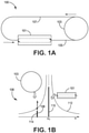
- FIG. 1A is a diagram illustrating a system 100 for injection locking a frequency of a laser produced by a laser source 101 using a laser fed back from an optical resonator 103.
- the system 100 includes a laser source 101.
- the laser source 101 may be capable of producing one or more lasers at different longitudinal modes.
- the laser source 101 may be a ring laser or linear laser source.
- the laser source 101 may be coupled through an optical path 105 to an optical resonator 103.
- the optical resonator 103 may provide an output laser at the resonance frequency from an output that is coupled through the optical path 107 to an input of the laser source 101.
- Both the reflection and transmission port of the optical resonator 103 may be used to provide feedback to the laser source 101.
- Some embodiments, such as the embodiment shown in FIG. 1A use the transmission port for providing feedback because the output from the reflection port may contain some mode distortion due to mode mismatch.
- the output laser provided by the optical resonator 103 to the laser source 101 through the optical path 107 may injection lock the laser produced by the laser source 101 to the resonance frequency of the optical resonator 103.
- injection locking occurs when a first oscillator, producing a laser at a first frequency (a launch frequency), is disturbed by a second laser at a second frequency, where the second frequency is close to the first frequency.
- the second laser may capture the first laser such that the frequencies of the first laser and the second laser become essentially identical.
- the output light provided by the optical resonator 103 at the resonance frequency of the optical resonator 103 may capture the laser produced by the laser source 101 such that the laser produced by the laser source 101 is substantially equivalent to the resonance frequency of the optical resonator 103.
- FIG. 1B is a graph 106 illustrating the effects of injection locking within the system 100.
- the laser source 101 may produce laser light having various frequency components along the gain curve 112.
- the laser source 101 may produce a laser at an initial launch frequency ( ⁇ 0 ) 110 that is supported by a stand-alone laser cavity.
- the launch frequency 110 is getting close to the resonance peak frequency 114 of the optical resonator 103
- the laser may then propagate around the optical resonator 103.
- the phase and intensity of the output beam follow the transmission function of the optical resonator 103, which means the optical resonator103 provides the strongest feedback at the resonance peak frequency 114.
- the original laser light at the initial launch frequency 110 may fail to be regeneratively amplified due to a lack of feedback.
- the feedback near resonance frequency 114 may perturb the laser provided by the laser source 101 such that the launch frequency of the laser source 101 moves from the initial launch frequency 110 towards an injection-locked frequency 108.
- the injection-locked frequency 108 is substantially equal to the resonance frequency 114.
- the laser source 101 may provide a laser at a launch frequency that is locked to the resonance frequency 114.
- the motion of the optical resonator 103 may be coupled to the motion of an object.
- the optical resonator 103 may similarly rotate about an axis.
- the length of the optical path through the optical resonator 103 may change.
- the resonance frequency 114 of the optical resonator 103 As the optical path through the optical resonator 103 changes, so does the resonance frequency 114 of the optical resonator 103.
- the laser coupled from the optical resonator 103 into the laser source 101 will cause the frequency of the laser provided by the laser source 101 to lock to the changing resonance frequency 114 of the optical resonator 103.
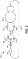
- FIG. 2 is a diagram illustrating an embodiment of an injection-locked RFOG 200.
- the RFOG 200 may include a laser source 201 and an optical resonator 203 that functions similarly as described above with respect to the laser source 101 and the optical resonator 103.
- the laser source 201 may produce a laser that produces two longitudinal modes, where the longitudinal modes are separated by a free spectral range of the optical resonator 203.
- a free spectral range of the optical resonator 203 may refer to the frequency difference between adjacent resonance frequencies of the optical resonator 203.
- one portion of the laser produced by the laser source 201 may propagate in the CW direction around the optical resonator 203, and another portion of the laser may propagate in the CCW direction around the optical resonator 203.
- the output of the optical resonator 203 may be coupled through an optical path 215, where the optical path 215 is also coupled to an input of the laser source 201.
- the resonance frequency of the optical resonator 203 may be sufficiently proximate to the frequency of the lasers produced by the laser source 201 to lock the frequency of the laser produced by the laser source 201 to the resonance frequency of the optical resonator 203. Accordingly, as the RFOG 200 rotates about an axis, causing the resonance frequencies of the optical resonator 203 to change due to changes in the propagation length of the optical paths through the optical resonator 203, the lasers produced by the laser source 201 may also change with the changing resonance frequencies of the optical resonator 203.
- the lasers produced by the laser source 201 may be used to detect rotation of the RFOG 200.
- the two longitudinal modes from the laser source 201 may provide the lasers to a rate detector 209.
- the rate detector 209 may be any device capable of detecting the lasers produced by the laser source 201 and determining rotation rates of the RFOG 200 based on the detected lasers.
- the rate detector 209 may include a tap to extract some of the laser beams from the laser source 201.
- the multiple lasers produced by the laser source 201 interfere at detector 209 and generate a signal having a beat frequency that can be used for rotation rate calculation.
- the rate detector 209 may detect the lasers produced by the laser source 201 and provide the electrical signals to a processor.
- the processor may process information in the signals to calculate rotation rate information for the RFOG 200.
- one or more computational devices such as a processor or other computational device, used in the present system and methods may be implemented using software, firmware, hardware, circuitry, or any appropriate combination thereof.
- the one or more computational devices may be supplemented by, or incorporated in, specially-designed application-specific integrated circuits (ASICSs) or field programmable gate arrays (FPGAs).
- ASICSs application-specific integrated circuits
- FPGAs field programmable gate arrays
- the one or more computational devices can also include or function with software programs, firmware, or other computer-readable instructions for carrying out various process tasks, calculations, and control functions that use the information provided by the RFOG 200.
- Instructions for carrying out the various process tasks, calculations, and generation of other data associated with the processing of rotation rate information can be implemented in software, firmware, or other computer-readable instructions. These instructions are typically stored on any appropriate computer program product that includes a computer-readable medium used for storage of computer-readable instructions or data structures. Such a computer-readable medium can be any available media that can be accessed by a general-purpose or special-purpose computer or processor, or any programmable logic device.
- Suitable computer-readable storage media may include, for example, nonvolatile memory devices including semiconductor memory devices such as Random Access Memory (RAM), Read Only Memory (ROM), Electrically Erasable Programmable ROM (EEPROM), or flash memory devices; magnetic disks such as internal hard disks or removable disks; optical storage devices such as compact discs (CDs), digital versatile discs (DVDs), Blu-ray discs; or any other media that can be used to carry or store desired program code in the form of computer-executable instructions or data structures.
- nonvolatile memory devices including semiconductor memory devices such as Random Access Memory (RAM), Read Only Memory (ROM), Electrically Erasable Programmable ROM (EEPROM), or flash memory devices; magnetic disks such as internal hard disks or removable disks; optical storage devices such as compact discs (CDs), digital versatile discs (DVDs), Blu-ray discs; or any other media that can be used to carry or store desired program code in the form of computer-executable instructions or data structures.
- the RFOG 200 may couple the lasers produced by the laser source 201 into either the CW path or the CCW path through the optical resonator 203 based on the frequencies of the lasers.
- the laser source 201 may produce lasers that are in different longitudinal modes.
- an unbalanced interferometer such as a Mach-Zehnder interferometer
- a delay line 217 is chosen to generate a Pi phase shift in delay time between these two lasers with different frequencies propagating in different arms of the unbalanced interferometer. Therefore, the two laser beams are separated at the unbalanced interferometer output, coupler 213.
- the coupler 213 will send the first laser into the CW path for the optical resonator 203, and the coupler 213 will send a second laser (that is 90 degrees out of phase with the first laser) into the CCW path of the optical resonator 203.
- a phase controller 211 may be controlled by a processor, circuitry, or other types of control devices to perform resonance switching.
- the phase controller 211 (for example, a heater or other phase controlling device) may modify the phase delay in the optical path such that the phase difference between two arms shift by ⁇ .
- the first laser and the second laser switch to different output arms of the coupler 213.
- the first laser may be propagating through the CW path
- the second laser may be propagating through the CCW path of the optical resonator 203.
- a controlling device may perform an output switch to drive the phase controller 211 to change the relative phase relationship of the two output arms of the coupler 213 to cause the first laser to now propagate through the CCW path and the second laser to propagate through the CW path of the optical resonator 203.
- the controlling device may perform periodic output switches. For example, the controlling device directs the phase controller 211 to cause the output switches to occur periodically such that, over time, both the first laser and the second laser are propagating at the same average frequency. Output switching or resonance switching may help reduce free spectral range errors that may arise during the operation of the RFOG 200.
- the RFOG 200 may include various components 219 that prevent light from propagating back into the coupler 213 and the laser source 201.
- the components 219 may include circulators, isolators, or other types of optical components that allow light to be transmitted along a first transmission path and not return along the first transmission path in the opposite direction. Accordingly, backscattered light and other light emitted from the optical resonator 203 are unable to propagate back into the coupler 213, laser source 201, and other optical components of the RFOG 200.
- the components 219 prevent undesirable light propagating within the RFOG 200 from negatively affecting optical measurements within the RFOG 200.
- the RFOG 200 may implement injection locking to drive the laser source 201 to produce lasers having launch frequencies substantially equal to two adjacent resonance frequencies of the RFOG 200 to reduce the need for high-powered lasers and expensive control loops.
- the lower intracavity power usage may reduce the Kerr effect and eliminate the use of high-quality intensity servo loops.
- injection locking may allow the RFOG 200 to operate without incorporating complex Pound Drever Hall loops.
- FIG. 3 is a diagram illustrating an injection-locked RFOG 300.
- the RFOG 300 in a substantially similar manner as the RFOG 200 described above in FIG. 2 .
- the optical resonator 303, the path 315, the rate detector 309, the coupler 313, the phase controller 311, the delay line 317, and the component 319 function substantially similar to the optical resonator 203, the path 215, the rate detector 209, the coupler 213, the phase controller 211, the delay line 217, and the component 219 in FIG. 2 .
- the RFOG 300 includes a ring laser 301 as the laser source.
- the injected lasers provided to the ring laser 301 from the optical resonator 303 through the path 315 may be coupled into the ring laser 301.
- the external feedback may cause the frequency of the laser provided by the ring laser 301 to track the resonance frequency of the optical resonator 303.
- FIG. 4 is a diagram illustrating an additional embodiment of an injection-locked RFOG 400.
- the injection-locked RFOG 400 may include multiple laser sources that each receive injection feedback at resonance frequencies of an optical resonator 403 from the optical resonator 403 that cause the laser sources to lock at the resonance frequencies.
- the RFOG 400 includes a first stimulated Brillouin scattering (SBS) laser source 423 and a second SBS laser source 425 as laser sources for the optical resonator 403.
- SBS stimulated Brillouin scattering
- the RFOG 400 may also include a pump laser source 421.
- the pump laser source 421 may be any laser source capable of producing a laser at a frequency that will cause an SBS laser source to produce a laser at or near the resonance frequency of the optical resonator 403.
- the pump laser source 421 may produce a pump laser that is coupled into two different fiber optic rings.
- the pump laser may be coupled into the first SBS laser source 423, which may include a first resonator ring.
- the pump laser is coupled into the first SBS laser source 423 in a CCW direction, stimulating Brillouin scattering in the CW direction within the first SBS laser source 423.
- the SBS is coupled from the first SBS laser source 423 into the optical resonator 403, such that the laser propagates in the CW direction within the optical resonator 403.
- the pump laser may be coupled into the second SBS laser source 425 in a CW direction.
- the pump laser may incite stimulated Brillouin scattering within the second SBS laser source 425.
- the SBS is coupled out of the second SBS laser source 425 and into the optical resonator 403, such that the laser propagates in the CCW direction within the optical resonator 403.
- the light resonates within the optical resonator 403 in a similar manner to the way that the light resonates within the optical resonator 203 and 303 described above in connection with FIGs. 2 and 3 .
- the lasers propagating within the optical resonator 403 are coupled out of the optical resonator 403 and back to the first SBS laser source 423 and the second SBS laser source 425 along separate return paths.
- the laser propagating in the CW direction within the optical resonator 403 is coupled out of the optical resonator 403 along the return path 427 such that the optical feedback is coupled into the first SBS laser source 423 in the CW direction.
- the laser propagating in the CCW direction within the optical resonator 403 is coupled out of the optical resonator 403 along the return path 429 such that the output laser is coupled into the second SBS laser source 425 in the CCW direction.
- the return paths 427 and 429 may couple respective optical feedback through one or more of an optical fiber and an optical waveguide.
- the output lasers from the optical resonator 403 may lock the SBS lasers to the resonance frequency of the optical resonator 403.
- an optical feedback at the CW resonance frequency may be provided to the first SBS laser source 423 through the return path 427.
- the CW resonance frequency of the optical resonator 403 is sufficiently close to the frequency of the laser provided by the first SBS laser source 423, the frequency of the laser from the first SBS laser source 423 may lock to the CCW resonance frequency of the output laser from the optical resonator 403.
- an optical feedback at the CCW resonance frequency may be provided to the second SBS laser source 425 through the return path 429.
- the frequency of the output laser from the second SBS laser source 425 may lock to the CCW resonance frequency of the output laser from the optical resonator 403.
- the rate detector 409 which functions similarly to the rate detectors 209 and 309 may detect rates of rotation for the RFOG 400 based on the detected beat frequency between lasers from the SBS laser sources 423 and 425.
- the RFOG 400 may operate without protections against back scattering or other light propagating in the wrong direction that may be provided by the optical resonator 403 to the SBS laser sources 423 and 425 through paths 437 and 439.
- the optical resonator 403 may provide light back towards the SBS laser sources 423 and 425 in the opposite direction of the light emitted by the SBS laser sources 423 and 425 towards the optical resonator 403. This light may include the laser provided by the other SBS laser source and backscattered light from the laser provided to the optical resonator 403.
- the optical resonator 403 may provide a CCW propagating optical feedback to the first SBS laser source 423, which was originally provided to the optical resonator 403 by the second SBS laser source 425. Additionally, the optical resonator 403 may provide backscattered light to the first SBS laser source 423 that is backscattered light from the CW propagating light provided by the first SBS laser source 423 to the optical resonator 403.
- the optical resonator 403 may provide a CW propagating optical feedback to the second SBS laser source 425, which was originally provided to the optical resonator 403 by the first SBS laser source 423. Additionally, the optical resonator 403 may provide backscattered light to the second SBS laser source 425 that is backscattered light from the CCW propagating light provided by the second SBS laser source 425 to the optical resonator 403.
- the unwanted laser feedback will not affect the emission of lasers toward the optical resonator 403 by the SBS laser sources 423 and 425.
- backscattered light does not affect the measurement of the CW and CCW resonance frequencies used to determine rotation rate information.
- optical isolators in paths 437 and 439 may be used to block unwanted back-reflection, the RFOG 400 may also operate without isolators to simplify and save costs associated with gyro configurations.
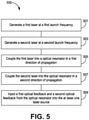
- FIG. 5 is a flowchart diagram of a method 500 for providing an injection-locked RFOG.
- the method 500 proceeds at 501, where a first laser is generated at a first launch frequency. Also, the method proceeds at 503, where a second laser is generated at a second launch frequency. Further, the method proceeds at 505, where the first laser is coupled into an optical resonator in a first direction of propagation. Moreover, the method proceeds at 507, where the second laser is coupled into the optical resonator in a second direction of propagation.
- the method 500 proceeds at 509, where a first optical feedback and a second optical feedback from the optical resonator are injected into the at least one laser source.
- the injected first output laser and the injected second output laser may cause the first laser and the second laser to lock to the resonance frequencies of the fiber optic resonator as described above.
Landscapes
- Physics & Mathematics (AREA)
- Electromagnetism (AREA)
- Engineering & Computer Science (AREA)
- Optics & Photonics (AREA)
- Plasma & Fusion (AREA)
- Power Engineering (AREA)
- General Physics & Mathematics (AREA)
- Radar, Positioning & Navigation (AREA)
- Remote Sensing (AREA)
- Gyroscopes (AREA)
- Lasers (AREA)
Abstract
Description
- Gyroscopes (also widely referred to as gyros) have been used to measure rotation rates or changes in angular velocity about an axis of rotation. A basic conventional fiber optic gyro (FOG) may include a light source, a beam generating device, and a coil of optical fiber coupled to the beam generating device that encircles an area. The beam generating device may transmit light beams into the coil that propagate in a clockwise (CW) direction and a counterclockwise (CCW) direction along the core of the optical fiber. Many FOGs utilize glass-based optical fibers that guide light along a solid glass core of the fiber. The two counter-propagating (e.g., CW and CCW) beams experience different pathlengths while propagating around a rotating closed optical path, and the difference in the two pathlengths is proportional to the rotational rate that is normal to the enclosed area.
- In an optical resonator fiber optic gyroscope (RFOG), the counter-propagating light beams are typically highly coherent and circulate through multiple turns of the fiber optic coil and for multiple passes through the coil using a device, such as a fiber coupler, that redirects a portion of the light that has passed through the coil back into the coil again (i.e., circulates the light). The beam generating device modulates and/or shifts the frequencies of each of the counter-propagating light beams so that the resonance frequencies of the resonant coil may be observed. The resonance frequencies for each of the CW and CCW paths through the coil are based on a constructive interference condition. This constructive interference condition arises when the light-waves traverse the coil a different number of times and become in phase with one another. When the light is circulating in phase within the coil, the light will add constructively at any point within the coil. As a result of this constructive interference condition, an optical wave having a wavelength λ is referred to as "on resonance" when the round-trip resonator optical pathlength is equal to an integral number of the wavelength λ.
- Rotation about the axis of the coil produces a different optical pathlength for CW and CCW propagation. The difference in optical pathlength causes the CW and CCW resonance frequencies of the optical resonator to change. The difference between the CW and CCW resonance frequencies can be measured by detecting CW and CCW propagating light beams that have been tuned to match their respective resonance frequency of the closed optical path. The measured difference can then be used to calculate the rotation rate.
- Systems and methods for an injection locking RFOG are described herein. In certain embodiments, a system includes an optical resonator. The system also includes at least one laser source configured to launch a first laser for propagating within the optical resonator in a first direction and launch a second laser for propagating within the optical resonator in a second direction that is opposite to the first direction, wherein the first laser is emitted by the at least one laser source at a first launch frequency and the second laser is emitted by the at least one laser source at a second launch frequency. Moreover, the system includes at least one return path that injects a first optical feedback, associated with the first laser, and a second optical feedback, associated with the second laser, from the optical resonator into the at least one laser source, wherein the first optical feedback locks the first launch frequency to a first resonance frequency of the optical resonator and the second optical feedback locks the second launch frequency to a second resonance frequency of the optical resonator.
- Understanding that the drawings depict only some embodiments and are not, therefore, to be considered limiting in scope, the exemplary embodiments will be described with additional specificity and detail using the accompanying drawings, in which:
-
FIG. 1A is a diagram illustrating a system for injection locking a frequency of a laser using an optical resonator according to an aspect of the present disclosure; -
FIG. 1B is a graph illustrating the effects of injection locking a frequency of a laser using an optical resonator according to an aspect of the present disclosure; -
FIG. 2 is a diagram illustrating an embodiment of an injection-locked RFOG according to an aspect of the present disclosure; -
FIG. 3 is a diagram illustrating a further embodiment of an injection-locked RFOG according to an aspect of the present disclosure; -
FIG. 4 is a diagram illustrating an additional embodiment of an injection-locked RFOG according to an aspect of the present disclosure; and -
FIG. 5 is a flowchart diagram of a method for providing an injection-locked RFOG according to an aspect of the present disclosure. - Per common practice, the various described features are not drawn to scale but are drawn to emphasize specific features relevant to the example embodiments.
- In the following detailed description, reference is made to the accompanying drawings that form a part hereof, and in which is shown by way of illustration specific illustrative embodiments. However, it is to be understood that other embodiments may be utilized and that logical, mechanical, and electrical changes may be made.
- Systems and methods described herein provide for an injection locking resonator fiber optic gyroscope (RFOG). For example, a laser source may be a single laser source or multiple laser sources. The laser source may produce one or more lasers near or at a resonance frequency of an optical resonator, which lasers are respectively coupled into an optical resonator in a clockwise (CW) and a counterclockwise (CCW) direction. The lasers propagating within the optical resonator are coupled out of the optical resonator and coupled, as an input, back into the laser source. As the laser source produces a laser that is near the resonance frequency of the optical resonator and the laser coupled from the optical resonator into the laser source is at the resonance frequency, the lasers produced by the laser source may lock to the resonance frequencies provided from the optical resonator. In other words, the laser frequency is no longer fixed by the laser cavity. The light that is coupled into the laser cavity carries the resonance information of the external resonator and plays a vital role in determining the laser frequency and phase noise.
- Frequently, RFOGs use relatively high-power lasers to improve the shot-noise limit called for by the angle random walk (ARW) to meet design requirements for different systems. However, the increased laser power may cause larger refractive index variation within the RFOG due to the Kerr effect. Some gyroscopes compensate for the Kerr effect by including high-quality intensity servo loops to reduce the bias instability caused by the laser intensity fluctuations. Also, RFOGs typically use complex loops to lock lasers to resonator resonance peaks, such as Pound-Drever-Hall (PDH) loops. By injection locking a laser produced by a laser source, an RFOG may be designed as described below that reduces the Kerr effect and allows for an operational RFOG that doesn't require high-quality locking loops.
-
FIG. 1A is a diagram illustrating asystem 100 for injection locking a frequency of a laser produced by alaser source 101 using a laser fed back from anoptical resonator 103. As shown, thesystem 100 includes alaser source 101. Thelaser source 101 may be capable of producing one or more lasers at different longitudinal modes. Thelaser source 101 may be a ring laser or linear laser source. Thelaser source 101 may be coupled through anoptical path 105 to anoptical resonator 103. When the frequency of thelaser source 101 is within the resonance peak of theoptical resonator 103, a portion of the received laser may resonate within theoptical resonator 103 at a resonance frequency, where the resonance frequency is dependent upon the periodic length of the fiber within theoptical resonator 103 and the wavelength of a laser propagating therein. Further, theoptical resonator 103 may provide an output laser at the resonance frequency from an output that is coupled through theoptical path 107 to an input of thelaser source 101. Both the reflection and transmission port of theoptical resonator 103 may be used to provide feedback to thelaser source 101. Some embodiments, such as the embodiment shown inFIG. 1A , use the transmission port for providing feedback because the output from the reflection port may contain some mode distortion due to mode mismatch. - In certain embodiments, the output laser provided by the
optical resonator 103 to thelaser source 101 through theoptical path 107 may injection lock the laser produced by thelaser source 101 to the resonance frequency of theoptical resonator 103. As known to one having skill in the art, injection locking occurs when a first oscillator, producing a laser at a first frequency (a launch frequency), is disturbed by a second laser at a second frequency, where the second frequency is close to the first frequency. When the first and second frequencies are close enough to one another, the second laser may capture the first laser such that the frequencies of the first laser and the second laser become essentially identical. With regards to thesystem 100, the output light provided by theoptical resonator 103 at the resonance frequency of theoptical resonator 103 may capture the laser produced by thelaser source 101 such that the laser produced by thelaser source 101 is substantially equivalent to the resonance frequency of theoptical resonator 103. -
FIG. 1B is agraph 106 illustrating the effects of injection locking within thesystem 100. As shown, thelaser source 101 may produce laser light having various frequency components along thegain curve 112. Upon startup, thelaser source 101 may produce a laser at an initial launch frequency (ω0) 110 that is supported by a stand-alone laser cavity. When thelaunch frequency 110 is getting close to theresonance peak frequency 114 of theoptical resonator 103, the laser may then propagate around theoptical resonator 103. The phase and intensity of the output beam follow the transmission function of theoptical resonator 103, which means the optical resonator103 provides the strongest feedback at theresonance peak frequency 114. Accordingly, the original laser light at theinitial launch frequency 110 may fail to be regeneratively amplified due to a lack of feedback. In certain embodiments, the feedback nearresonance frequency 114 may perturb the laser provided by thelaser source 101 such that the launch frequency of thelaser source 101 moves from theinitial launch frequency 110 towards an injection-lockedfrequency 108. As shown, the injection-lockedfrequency 108 is substantially equal to theresonance frequency 114. Thus, thelaser source 101 may provide a laser at a launch frequency that is locked to theresonance frequency 114. - In certain embodiments, the motion of the
optical resonator 103 may be coupled to the motion of an object. For example, when the object is rotating about an axis, theoptical resonator 103 may similarly rotate about an axis. In some configurations, when theoptical resonator 103 rotates about an axis, the length of the optical path through theoptical resonator 103 may change. As the optical path through theoptical resonator 103 changes, so does theresonance frequency 114 of theoptical resonator 103. Also, as theresonance frequency 114 changes, the laser coupled from theoptical resonator 103 into thelaser source 101 will cause the frequency of the laser provided by thelaser source 101 to lock to the changingresonance frequency 114 of theoptical resonator 103. -
FIG. 2 is a diagram illustrating an embodiment of an injection-lockedRFOG 200. As shown, theRFOG 200 may include alaser source 201 and anoptical resonator 203 that functions similarly as described above with respect to thelaser source 101 and theoptical resonator 103. However, in certain embodiments, thelaser source 201 may produce a laser that produces two longitudinal modes, where the longitudinal modes are separated by a free spectral range of theoptical resonator 203. As used herein, a free spectral range of theoptical resonator 203 may refer to the frequency difference between adjacent resonance frequencies of theoptical resonator 203. Depending on the longitudinal mode, one portion of the laser produced by thelaser source 201 may propagate in the CW direction around theoptical resonator 203, and another portion of the laser may propagate in the CCW direction around theoptical resonator 203. - In some embodiments, the output of the
optical resonator 203 may be coupled through anoptical path 215, where theoptical path 215 is also coupled to an input of thelaser source 201. As described above, the resonance frequency of theoptical resonator 203 may be sufficiently proximate to the frequency of the lasers produced by thelaser source 201 to lock the frequency of the laser produced by thelaser source 201 to the resonance frequency of theoptical resonator 203. Accordingly, as theRFOG 200 rotates about an axis, causing the resonance frequencies of theoptical resonator 203 to change due to changes in the propagation length of the optical paths through theoptical resonator 203, the lasers produced by thelaser source 201 may also change with the changing resonance frequencies of theoptical resonator 203. - In further embodiments, as the lasers produced by the
laser source 201 track the changes in the resonance frequencies of theoptical resonator 203 caused by the rotation of theRFOG 200, the lasers produced by thelaser source 201 may be used to detect rotation of theRFOG 200. For example, the two longitudinal modes from thelaser source 201 may provide the lasers to arate detector 209. Therate detector 209 may be any device capable of detecting the lasers produced by thelaser source 201 and determining rotation rates of theRFOG 200 based on the detected lasers. For example, therate detector 209 may include a tap to extract some of the laser beams from thelaser source 201. The multiple lasers produced by thelaser source 201 interfere atdetector 209 and generate a signal having a beat frequency that can be used for rotation rate calculation. - In some embodiments, the
rate detector 209 may detect the lasers produced by thelaser source 201 and provide the electrical signals to a processor. The processor may process information in the signals to calculate rotation rate information for theRFOG 200. As used herein, one or more computational devices, such as a processor or other computational device, used in the present system and methods may be implemented using software, firmware, hardware, circuitry, or any appropriate combination thereof. The one or more computational devices may be supplemented by, or incorporated in, specially-designed application-specific integrated circuits (ASICSs) or field programmable gate arrays (FPGAs). The one or more computational devices can also include or function with software programs, firmware, or other computer-readable instructions for carrying out various process tasks, calculations, and control functions that use the information provided by theRFOG 200. - Instructions for carrying out the various process tasks, calculations, and generation of other data associated with the processing of rotation rate information can be implemented in software, firmware, or other computer-readable instructions. These instructions are typically stored on any appropriate computer program product that includes a computer-readable medium used for storage of computer-readable instructions or data structures. Such a computer-readable medium can be any available media that can be accessed by a general-purpose or special-purpose computer or processor, or any programmable logic device.
- Suitable computer-readable storage media may include, for example, nonvolatile memory devices including semiconductor memory devices such as Random Access Memory (RAM), Read Only Memory (ROM), Electrically Erasable Programmable ROM (EEPROM), or flash memory devices; magnetic disks such as internal hard disks or removable disks; optical storage devices such as compact discs (CDs), digital versatile discs (DVDs), Blu-ray discs; or any other media that can be used to carry or store desired program code in the form of computer-executable instructions or data structures.
- In certain embodiments, the
RFOG 200 may couple the lasers produced by thelaser source 201 into either the CW path or the CCW path through theoptical resonator 203 based on the frequencies of the lasers. As stated above, thelaser source 201 may produce lasers that are in different longitudinal modes. As shown, an unbalanced interferometer (such as a Mach-Zehnder interferometer) may be used to separate two laser waves with different frequencies. Adelay line 217 is chosen to generate a Pi phase shift in delay time between these two lasers with different frequencies propagating in different arms of the unbalanced interferometer. Therefore, the two laser beams are separated at the unbalanced interferometer output,coupler 213. Thecoupler 213 will send the first laser into the CW path for theoptical resonator 203, and thecoupler 213 will send a second laser (that is 90 degrees out of phase with the first laser) into the CCW path of theoptical resonator 203. - In some embodiments, a
phase controller 211 may be controlled by a processor, circuitry, or other types of control devices to perform resonance switching. In particular, the phase controller 211 (for example, a heater or other phase controlling device) may modify the phase delay in the optical path such that the phase difference between two arms shift by π. Accordingly, the first laser and the second laser switch to different output arms of thecoupler 213. For example, at a first time, the first laser may be propagating through the CW path, and the second laser may be propagating through the CCW path of theoptical resonator 203. At a second time, a controlling device may perform an output switch to drive thephase controller 211 to change the relative phase relationship of the two output arms of thecoupler 213 to cause the first laser to now propagate through the CCW path and the second laser to propagate through the CW path of theoptical resonator 203. The controlling device may perform periodic output switches. For example, the controlling device directs thephase controller 211 to cause the output switches to occur periodically such that, over time, both the first laser and the second laser are propagating at the same average frequency. Output switching or resonance switching may help reduce free spectral range errors that may arise during the operation of theRFOG 200. - Additionally, the
RFOG 200 may includevarious components 219 that prevent light from propagating back into thecoupler 213 and thelaser source 201. Thecomponents 219 may include circulators, isolators, or other types of optical components that allow light to be transmitted along a first transmission path and not return along the first transmission path in the opposite direction. Accordingly, backscattered light and other light emitted from theoptical resonator 203 are unable to propagate back into thecoupler 213,laser source 201, and other optical components of theRFOG 200. Thus, thecomponents 219 prevent undesirable light propagating within theRFOG 200 from negatively affecting optical measurements within theRFOG 200. - As shown, the
RFOG 200 may implement injection locking to drive thelaser source 201 to produce lasers having launch frequencies substantially equal to two adjacent resonance frequencies of theRFOG 200 to reduce the need for high-powered lasers and expensive control loops. The lower intracavity power usage may reduce the Kerr effect and eliminate the use of high-quality intensity servo loops. Also, injection locking may allow theRFOG 200 to operate without incorporating complex Pound Drever Hall loops. -
FIG. 3 is a diagram illustrating an injection-lockedRFOG 300. TheRFOG 300 in a substantially similar manner as theRFOG 200 described above inFIG. 2 . For example, theoptical resonator 303, thepath 315, therate detector 309, thecoupler 313, thephase controller 311, thedelay line 317, and thecomponent 319 function substantially similar to theoptical resonator 203, thepath 215, therate detector 209, thecoupler 213, thephase controller 211, thedelay line 217, and thecomponent 219 inFIG. 2 . However, theRFOG 300 includes aring laser 301 as the laser source. Accordingly, the injected lasers provided to thering laser 301 from theoptical resonator 303 through thepath 315 may be coupled into thering laser 301. As the resonance of theoptical resonator 303 is sufficiently close in frequency to the laser provided by thering laser 301, the external feedback may cause the frequency of the laser provided by thering laser 301 to track the resonance frequency of theoptical resonator 303. -
FIG. 4 is a diagram illustrating an additional embodiment of an injection-lockedRFOG 400. In contrast to theRFOG 200 and theRFOG 300, the injection-lockedRFOG 400 may include multiple laser sources that each receive injection feedback at resonance frequencies of anoptical resonator 403 from theoptical resonator 403 that cause the laser sources to lock at the resonance frequencies. In particular, theRFOG 400 includes a first stimulated Brillouin scattering (SBS)laser source 423 and a secondSBS laser source 425 as laser sources for theoptical resonator 403. Additionally, to stimulate the Brillouin scattering within the firstSBS laser source 423 and the secondSBS laser source 425, theRFOG 400 may also include apump laser source 421. - In certain embodiments, the
pump laser source 421 may be any laser source capable of producing a laser at a frequency that will cause an SBS laser source to produce a laser at or near the resonance frequency of theoptical resonator 403. Thepump laser source 421 may produce a pump laser that is coupled into two different fiber optic rings. For example, the pump laser may be coupled into the firstSBS laser source 423, which may include a first resonator ring. The pump laser is coupled into the firstSBS laser source 423 in a CCW direction, stimulating Brillouin scattering in the CW direction within the firstSBS laser source 423. The SBS is coupled from the firstSBS laser source 423 into theoptical resonator 403, such that the laser propagates in the CW direction within theoptical resonator 403. - Similarly, the pump laser may be coupled into the second
SBS laser source 425 in a CW direction. The pump laser may incite stimulated Brillouin scattering within the secondSBS laser source 425. The SBS is coupled out of the secondSBS laser source 425 and into theoptical resonator 403, such that the laser propagates in the CCW direction within theoptical resonator 403. - In some embodiments, the light resonates within the
optical resonator 403 in a similar manner to the way that the light resonates within theoptical resonator FIGs. 2 and3 . In contrast to theRFOGs optical resonator 403 are coupled out of theoptical resonator 403 and back to the firstSBS laser source 423 and the secondSBS laser source 425 along separate return paths. For example, the laser propagating in the CW direction within theoptical resonator 403 is coupled out of theoptical resonator 403 along thereturn path 427 such that the optical feedback is coupled into the firstSBS laser source 423 in the CW direction. Similarly, the laser propagating in the CCW direction within theoptical resonator 403 is coupled out of theoptical resonator 403 along thereturn path 429 such that the output laser is coupled into the secondSBS laser source 425 in the CCW direction. Thereturn paths - When the output optical feedback from the
optical resonator 403 is coupled into the respective SBS laser sources, the output lasers from theoptical resonator 403 may lock the SBS lasers to the resonance frequency of theoptical resonator 403. For example, an optical feedback at the CW resonance frequency may be provided to the firstSBS laser source 423 through thereturn path 427. As the CW resonance frequency of theoptical resonator 403 is sufficiently close to the frequency of the laser provided by the firstSBS laser source 423, the frequency of the laser from the firstSBS laser source 423 may lock to the CCW resonance frequency of the output laser from theoptical resonator 403. Similarly, an optical feedback at the CCW resonance frequency may be provided to the secondSBS laser source 425 through thereturn path 429. As the CCW resonance frequency of theoptical resonator 403 is sufficiently close to the frequency of the laser provided by the secondSBS laser source 425, the frequency of the output laser from the secondSBS laser source 425 may lock to the CCW resonance frequency of the output laser from theoptical resonator 403. Therate detector 409, which functions similarly to therate detectors RFOG 400 based on the detected beat frequency between lasers from theSBS laser sources - In some embodiments, by using
SBS laser sources optical resonator 403, theRFOG 400 may operate without protections against back scattering or other light propagating in the wrong direction that may be provided by theoptical resonator 403 to theSBS laser sources paths optical resonator 403 may provide light back towards theSBS laser sources SBS laser sources optical resonator 403. This light may include the laser provided by the other SBS laser source and backscattered light from the laser provided to theoptical resonator 403. For instance, theoptical resonator 403 may provide a CCW propagating optical feedback to the firstSBS laser source 423, which was originally provided to theoptical resonator 403 by the secondSBS laser source 425. Additionally, theoptical resonator 403 may provide backscattered light to the firstSBS laser source 423 that is backscattered light from the CW propagating light provided by the firstSBS laser source 423 to theoptical resonator 403. - Similarly, the
optical resonator 403 may provide a CW propagating optical feedback to the secondSBS laser source 425, which was originally provided to theoptical resonator 403 by the firstSBS laser source 423. Additionally, theoptical resonator 403 may provide backscattered light to the secondSBS laser source 425 that is backscattered light from the CCW propagating light provided by the secondSBS laser source 425 to theoptical resonator 403. As the light provided to the firstSBS laser source 423 and the secondSBS laser source 425 throughpaths SBS laser sources SBS laser sources optical resonator 403 by theSBS laser sources paths RFOG 400 may also operate without isolators to simplify and save costs associated with gyro configurations. -
FIG. 5 is a flowchart diagram of amethod 500 for providing an injection-locked RFOG. Themethod 500 proceeds at 501, where a first laser is generated at a first launch frequency. Also, the method proceeds at 503, where a second laser is generated at a second launch frequency. Further, the method proceeds at 505, where the first laser is coupled into an optical resonator in a first direction of propagation. Moreover, the method proceeds at 507, where the second laser is coupled into the optical resonator in a second direction of propagation. - In certain embodiments, the
method 500 proceeds at 509, where a first optical feedback and a second optical feedback from the optical resonator are injected into the at least one laser source. As the first output laser and the second output laser are at the resonance frequency of the fiber optic resonator, the injected first output laser and the injected second output laser may cause the first laser and the second laser to lock to the resonance frequencies of the fiber optic resonator as described above. -
- Example 1 includes a system comprising: an optical resonator; at least one laser source configured to launch a first laser for propagating within the optical resonator in a first direction and launch a second laser for propagating within the optical resonator in a second direction that is opposite to the first direction, wherein the first laser is emitted by the at least one laser source at a first launch frequency and the second laser is emitted by the at least one laser source at a second launch frequency; and at least one return path that injects a first optical feedback, associated with the first laser, and a second optical feedback, associated with the second laser, from the optical resonator into the at least one laser source, wherein the first optical feedback locks the first launch frequency to a first resonance frequency of the optical resonator and the second optical feedback locks the second launch frequency to a second resonance frequency of the optical resonator.
- Example 2 includes the system of Example 1, wherein the at least one laser source is a single laser source that produces the first laser at a first longitudinal mode and the second laser at a second longitudinal mode.
- Example 3 includes the system of any of Examples 1-2, wherein the at least one laser source comprises a first laser source that produces the first laser and a second laser source that produces the second laser.
- Example 4 includes the system of Example 3, wherein the first laser source is a first stimulated Brillouin scattering (SBS) laser source and the second laser source is a second SBS laser source.
- Example 5 includes the system of Example 4, further comprising a pump laser source that emits a pump laser into the first SBS laser source and the second SBS laser source, wherein stimulated Brillouin scattering within the first SBS laser source generates the first laser and stimulated Brillouin scattering within the second SBS laser source generates the second laser.
- Example 6 includes the system of any of Examples 4-5, wherein the at least one return path comprises a first return path that couples the first optical feedback into the first SBS laser source and a second return path that couples the second optical feedback into the second SBS laser source.
- Example 7 includes the system of any of Examples 1-6, further comprising an unbalanced interferometer that separates the first laser and the second laser and then couples the first laser and the second laser into the optical resonator in one of the first direction and the second direction based on a delay time in an arm of the unbalanced interferometer.
- Example 8 includes the system of Example 7, further comprising a phase controller configured to modify a phase delay for the unbalanced interferometer to perform output switches for the unbalanced interferometer, wherein the first laser and the second laser, output on different outputs of the unbalanced interferometer, switch between a first output of the unbalanced interferometer and a second output of the unbalanced interferometer during each output switch.
- Example 9 includes the system of any of Examples 1-8, further comprising a rate detector that detects a rate of rotation based on a beat frequency of the first laser and the second laser.
- Example 10 includes the system of any of Examples 1-9, wherein the at least one return path comprises at least one of: optical fiber; and optical waveguides.
- Example 11 includes a method comprising: generating a first laser at a first launch frequency from at least one laser source; generating a second laser at a second launch frequency from the at least one laser source; coupling the first laser into an optical resonator in a first direction of propagation within the optical resonator, wherein the optical resonator provides a first optical feedback associated with the first direction at a first resonance frequency; coupling the second laser into the optical resonator in a second direction of propagation within the optical resonator that is opposite to the first direction, wherein the optical resonator provides a second optical feedback associated with the second direction at a second resonance frequency; and injecting the first optical feedback and the second optical feedback into the at least one laser source such that the first launch frequency locks to the first resonance frequency and the second launch frequency locks to the second resonance frequency.
- Example 12 includes the method of Example 11, wherein the at least one laser source is a single laser source that produces the first laser at a first longitudinal mode and the second laser at a second longitudinal mode.
- Example 13 includes the method of any of Examples 11-12, wherein generating the first laser and generating the second laser comprises: generating the first laser at a first laser source; and generating the second laser at a second laser source.
- Example 14 includes the method of Example 13, wherein the first laser source is a first stimulated Brillouin scattering (SBS) laser source and the second laser source is a second SBS laser source.
- Example 15 includes the method of Example 14, wherein generating the first laser and the second laser comprises: providing a pump laser to the first SBS laser source, wherein Brillouin scattering within the first SBS laser source generates the first laser; and providing the pump laser to the second SBS laser source, wherein Brillouin scattering within the second SBS laser source generates the second laser.
- Example 16 includes the method of any of Examples 14-15, wherein injecting the first optical feedback and the second optical feedback into the at least one laser source comprises: coupling the first optical feedback into the first SBS laser source; and coupling the second optical feedback into the second SBS laser source.
- Example 17 includes the method of any of Examples 11-16, wherein the first laser and the second laser are coupled into the optical resonator in one of the first direction and the second direction based on a phase of the first laser with respect to the second laser.
- Example 18 includes the method of Example 17, further comprising a phase controller configured to periodically switch the phase of the first laser with respect to the second laser.
- Example 19 includes the method of any of Examples 11-18, further comprising detecting a rate of rotation based on a beat frequency of the first laser and the second laser.
- Example 20 includes a system comprising: an optical resonator; at least one laser source configured to launch a first laser for propagating within the optical resonator in a first direction and launch a second laser for propagating within the optical resonator in a second direction that is opposite to the first direction, wherein the first laser is emitted by the at least one laser source at a first launch frequency and the second laser is emitted by the at least one laser source at a second launch frequency; at least one return path that injects a first optical feedback, associated with the first laser, and a second optical feedback, associated with the second laser, from the optical resonator to the at least one laser source, wherein the first optical feedback locks the first launch frequency to a first resonance frequency of the optical resonator and the second optical feedback locks the second launch frequency to a second resonance frequency of the optical resonator; and a rate detector that detects a rate of rotation based on a beat frequency of the first laser and the second laser.
- Although specific embodiments have been illustrated and described herein, it will be appreciated by those of ordinary skill in the art that any arrangement, which is calculated to achieve the same purpose, may be substituted for the specific embodiments shown. Therefore, it is manifestly intended that this invention be limited only by the claims and the equivalents thereof.
Claims (10)
- A system comprising:an optical resonator (203);at least one laser source (201) configured to launch a first laser for propagating within the optical resonator (203) in a first direction and launch a second laser for propagating within the optical resonator (203) in a second direction that is opposite to the first direction, wherein the first laser is emitted by the at least one laser source (201) at a first launch frequency and the second laser is emitted by the at least one laser source (201) at a second launch frequency; andat least one return path (215)that injects a first optical feedback, associated with the first laser, and a second optical feedback, associated with the second laser, from the optical resonator (203) into the at least one laser source (201), wherein the first optical feedback locks the first launch frequency to a first resonance frequency of the optical resonator (203) and the second optical feedback locks the second launch frequency to a second resonance frequency of the optical resonator (203).
- The system of claim 1, wherein the at least one laser source (201) is a single laser source (201) that produces the first laser at a first longitudinal mode and the second laser at a second longitudinal mode.
- The system of claim 1, wherein the at least one laser source comprises a first laser source that produces the first laser and a second laser source that produces the second laser.
- The system of claim 3, wherein the first laser source is a first stimulated Brillouin scattering (SBS) laser source (423) and the second laser source is a second SBS laser source (425).
- The system of claim 4, further comprising a pump laser source (421) that emits a pump laser into the first SBS laser source (423) and the second SBS laser source (425), wherein stimulated Brillouin scattering within the first SBS laser source (423) generates the first laser and stimulated Brillouin scattering within the second SBS laser source (425) generates the second laser.
- The system of claim 4, wherein the at least one return path comprises a first return path (427) that couples the first optical feedback into the first SBS laser source (423) and a second return path (429) that couples the second optical feedback into the second SBS laser source (425).
- The system of claim 1, further comprising an unbalanced interferometer that separates the first laser and the second laser and then couples the first laser and the second laser into the optical resonator (203) in one of the first direction and the second direction based on a delay time in an arm of the unbalanced interferometer.
- The system of claim 7, further comprising a phase controller (211) configured to modify a phase delay for the unbalanced interferometer to perform output switches for the unbalanced interferometer, wherein the first laser and the second laser, output on different outputs of the unbalanced interferometer, switch between a first output of the unbalanced interferometer and a second output of the unbalanced interferometer during each output switch.
- A method comprising:generating a first laser at a first launch frequency from at least one laser source (201);generating a second laser at a second launch frequency from the at least one laser source (201);coupling the first laser into an optical resonator (203) in a first direction of propagation within the optical resonator (203), wherein the optical resonator (203) provides a first optical feedback associated with the first direction at a first resonance frequency;coupling the second laser into the optical resonator (203) in a second direction of propagation within the optical resonator (203) that is opposite to the first direction, wherein the optical resonator (203) provides a second optical feedback associated with the second direction at a second resonance frequency; andinjecting the first optical feedback and the second optical feedback into the at least one laser source (201) such that the first launch frequency locks to the first resonance frequency and the second launch frequency locks to the second resonance frequency.
- The method of claim 9, wherein the at least one laser source (201) is a single laser source (201) that produces the first laser at a first longitudinal mode and the second laser at a second longitudinal mode.
Applications Claiming Priority (1)
| Application Number | Priority Date | Filing Date | Title |
|---|---|---|---|
| US16/940,223 US11506495B2 (en) | 2020-07-27 | 2020-07-27 | Injection locking resonator fiber optic gyroscope |
Publications (2)
| Publication Number | Publication Date |
|---|---|
| EP3945646A1 true EP3945646A1 (en) | 2022-02-02 |
| EP3945646B1 EP3945646B1 (en) | 2025-12-10 |
Family
ID=76859562
Family Applications (1)
| Application Number | Title | Priority Date | Filing Date |
|---|---|---|---|
| EP21184889.0A Active EP3945646B1 (en) | 2020-07-27 | 2021-07-09 | Injection locking resonator fiber optic gyroscope |
Country Status (2)
| Country | Link |
|---|---|
| US (1) | US11506495B2 (en) |
| EP (1) | EP3945646B1 (en) |
Families Citing this family (3)
| Publication number | Priority date | Publication date | Assignee | Title |
|---|---|---|---|---|
| US11624615B2 (en) * | 2020-10-05 | 2023-04-11 | Anello Photonics, Inc. | Ring waveguide based integrated photonics optical gyroscope with balanced detection scheme |
| FR3121560A1 (en) * | 2021-04-01 | 2022-10-07 | Thales | Method for controlling an optical device comprising a laser and a cavity making it possible to compensate for an amplitude modulation introduced by a phase modulator |
| US12646902B1 (en) * | 2022-01-18 | 2026-06-02 | Hqphotonics Inc. | Laser reference frequency source stabilized by optical self-injection locking |
Citations (5)
| Publication number | Priority date | Publication date | Assignee | Title |
|---|---|---|---|---|
| US5134622A (en) * | 1990-12-20 | 1992-07-28 | Deacon Research | Diode-pumped optical parametric oscillator |
| US20040264977A1 (en) * | 2001-11-15 | 2004-12-30 | Daniel Yap | Method and apparatus for waveform generation |
| EP2333483A2 (en) * | 2009-12-13 | 2011-06-15 | Honeywell International Inc. | System and method for reducing laser phase noise in a resonator fiber optic gyroscope |
| US20110255094A1 (en) * | 2010-03-23 | 2011-10-20 | Oewaves, Inc. | Optical gyroscope sensors based on optical whispering gallery mode resonators |
| EP3093618A1 (en) * | 2015-05-11 | 2016-11-16 | Honeywell International Inc. | Systems and methods for resonance switching resonator fiber optic gyroscopes (rfogs) with feed-forward processing |
Family Cites Families (8)
| Publication number | Priority date | Publication date | Assignee | Title |
|---|---|---|---|---|
| JP2000171261A (en) * | 1998-12-09 | 2000-06-23 | Japan Aviation Electronics Industry Ltd | Multi-axis stimulated Brillouin scattering optical fiber velocimeter |
| CN1264000C (en) | 2002-04-03 | 2006-07-12 | 中国科学技术大学 | Self-injection locking fibre-optical laser circulator |
| US7372574B2 (en) * | 2005-12-09 | 2008-05-13 | Honeywell International Inc. | System and method for stabilizing light sources in resonator gyro |
| JP2009218488A (en) * | 2008-03-12 | 2009-09-24 | Mitsutoyo Corp | Device, method and program for stabilizing laser frequency |
| US8736845B2 (en) | 2011-05-24 | 2014-05-27 | Honeywell International Inc. | Frequency stabilized laser system |
| US9197032B2 (en) * | 2014-04-02 | 2015-11-24 | Honeywell International Inc. | Systems and methods for stabilized stimulated brillouin scattering lasers with ultra-low phase noise |
| CN107843248B (en) * | 2017-09-01 | 2021-05-14 | 长春理工大学 | Self-injection locking resonant optical gyroscope and its working method |
| CN110470292B (en) | 2019-08-30 | 2023-08-01 | 哈尔滨工程大学 | Self-injection frequency-locking resonant optical gyroscope and working method thereof |
-
2020
- 2020-07-27 US US16/940,223 patent/US11506495B2/en active Active
-
2021
- 2021-07-09 EP EP21184889.0A patent/EP3945646B1/en active Active
Patent Citations (5)
| Publication number | Priority date | Publication date | Assignee | Title |
|---|---|---|---|---|
| US5134622A (en) * | 1990-12-20 | 1992-07-28 | Deacon Research | Diode-pumped optical parametric oscillator |
| US20040264977A1 (en) * | 2001-11-15 | 2004-12-30 | Daniel Yap | Method and apparatus for waveform generation |
| EP2333483A2 (en) * | 2009-12-13 | 2011-06-15 | Honeywell International Inc. | System and method for reducing laser phase noise in a resonator fiber optic gyroscope |
| US20110255094A1 (en) * | 2010-03-23 | 2011-10-20 | Oewaves, Inc. | Optical gyroscope sensors based on optical whispering gallery mode resonators |
| EP3093618A1 (en) * | 2015-05-11 | 2016-11-16 | Honeywell International Inc. | Systems and methods for resonance switching resonator fiber optic gyroscopes (rfogs) with feed-forward processing |
Also Published As
| Publication number | Publication date |
|---|---|
| US20220026211A1 (en) | 2022-01-27 |
| US11506495B2 (en) | 2022-11-22 |
| EP3945646B1 (en) | 2025-12-10 |
Similar Documents
| Publication | Publication Date | Title |
|---|---|---|
| EP3945646B1 (en) | Injection locking resonator fiber optic gyroscope | |
| US8009296B2 (en) | Light-phase-noise error reducer | |
| US9197032B2 (en) | Systems and methods for stabilized stimulated brillouin scattering lasers with ultra-low phase noise | |
| US10197397B2 (en) | Small low cost resonator fiber optic gyroscope with reduced optical errors | |
| US5018857A (en) | Passive ring resonator gyro with polarization rotating ring path | |
| US10451421B2 (en) | Resonant fiber optical gyroscope using antiresonant nodeless fiber | |
| US9207082B2 (en) | Fiber resonator gyroscope with low round trip loss and high output power | |
| US11486706B2 (en) | Kerr effect reduction in SBS laser gyroscope | |
| US5517305A (en) | Brillouin ring laser gyro | |
| JPH05215556A (en) | Sensor | |
| EP4439011A1 (en) | Photonics gyroscope with broadband light source | |
| JP2001066142A (en) | Resonant optical gyro | |
| US5305087A (en) | Optical ring resonator sensor | |
| US11181374B2 (en) | Gyroscope with reduced bias errors due to resonance asymmetries | |
| US8687198B2 (en) | Coupled cavity dispersion enhanced ring laser gyroscope | |
| CN112066969B (en) | Dual-light source self-injection locked resonant micro-optical electromechanical gyroscope based on optical phase-locked loop | |
| JPH0722674A (en) | Optical ring resonator and passive ring resonant optical gyro using the optical ring resonator | |
| US11624614B1 (en) | Reducing rotation sensing errors from laser source signal and modulation cross-talk | |
| CN119374571A (en) | Optical gyroscope with broadband comb interrogation | |
| JP2011242173A (en) | Polarized wave stabilizing method for optical fiber gyro and device for realizing the same | |
| US11002544B2 (en) | RFOG resonance hopping | |
| US20220252400A1 (en) | Optical gyroscope with a resonator having bias error reduction | |
| US20250093158A1 (en) | Interferometric resonator optical gyroscope with optical frequency comb | |
| EP4567380B1 (en) | Optical circuit for compensating optical lead fluctuations in an rfog | |
| RU2751052C1 (en) | Differential multimode fiber laser gyroscope |
Legal Events
| Date | Code | Title | Description |
|---|---|---|---|
| PUAI | Public reference made under article 153(3) epc to a published international application that has entered the european phase |
Free format text: ORIGINAL CODE: 0009012 |
|
| STAA | Information on the status of an ep patent application or granted ep patent |
Free format text: STATUS: THE APPLICATION HAS BEEN PUBLISHED |
|
| AK | Designated contracting states |
Kind code of ref document: A1 Designated state(s): AL AT BE BG CH CY CZ DE DK EE ES FI FR GB GR HR HU IE IS IT LI LT LU LV MC MK MT NL NO PL PT RO RS SE SI SK SM TR |
|
| STAA | Information on the status of an ep patent application or granted ep patent |
Free format text: STATUS: REQUEST FOR EXAMINATION WAS MADE |
|
| 17P | Request for examination filed |
Effective date: 20220331 |
|
| RBV | Designated contracting states (corrected) |
Designated state(s): AL AT BE BG CH CY CZ DE DK EE ES FI FR GB GR HR HU IE IS IT LI LT LU LV MC MK MT NL NO PL PT RO RS SE SI SK SM TR |
|
| P01 | Opt-out of the competence of the unified patent court (upc) registered |
Effective date: 20230421 |
|
| STAA | Information on the status of an ep patent application or granted ep patent |
Free format text: STATUS: EXAMINATION IS IN PROGRESS |
|
| 17Q | First examination report despatched |
Effective date: 20250312 |
|
| GRAP | Despatch of communication of intention to grant a patent |
Free format text: ORIGINAL CODE: EPIDOSNIGR1 |
|
| STAA | Information on the status of an ep patent application or granted ep patent |
Free format text: STATUS: GRANT OF PATENT IS INTENDED |
|
| INTG | Intention to grant announced |
Effective date: 20250724 |
|
| GRAS | Grant fee paid |
Free format text: ORIGINAL CODE: EPIDOSNIGR3 |
|
| GRAA | (expected) grant |
Free format text: ORIGINAL CODE: 0009210 |
|
| STAA | Information on the status of an ep patent application or granted ep patent |
Free format text: STATUS: THE PATENT HAS BEEN GRANTED |
|
| AK | Designated contracting states |
Kind code of ref document: B1 Designated state(s): AL AT BE BG CH CY CZ DE DK EE ES FI FR GB GR HR HU IE IS IT LI LT LU LV MC MK MT NL NO PL PT RO RS SE SI SK SM TR |
|
| REG | Reference to a national code |
Ref country code: CH Ref legal event code: F10 Free format text: ST27 STATUS EVENT CODE: U-0-0-F10-F00 (AS PROVIDED BY THE NATIONAL OFFICE) Effective date: 20251210 Ref country code: GB Ref legal event code: FG4D |
|
| REG | Reference to a national code |
Ref country code: DE Ref legal event code: R096 Ref document number: 602021043987 Country of ref document: DE |
|
| REG | Reference to a national code |
Ref country code: IE Ref legal event code: FG4D |
|
| PG25 | Lapsed in a contracting state [announced via postgrant information from national office to epo] |
Ref country code: ES Free format text: LAPSE BECAUSE OF FAILURE TO SUBMIT A TRANSLATION OF THE DESCRIPTION OR TO PAY THE FEE WITHIN THE PRESCRIBED TIME-LIMIT Effective date: 20251210 |
|
| REG | Reference to a national code |
Ref country code: LT Ref legal event code: MG9D |
|
| PG25 | Lapsed in a contracting state [announced via postgrant information from national office to epo] |
Ref country code: NO Free format text: LAPSE BECAUSE OF FAILURE TO SUBMIT A TRANSLATION OF THE DESCRIPTION OR TO PAY THE FEE WITHIN THE PRESCRIBED TIME-LIMIT Effective date: 20260310 |
|
| PG25 | Lapsed in a contracting state [announced via postgrant information from national office to epo] |
Ref country code: FI Free format text: LAPSE BECAUSE OF FAILURE TO SUBMIT A TRANSLATION OF THE DESCRIPTION OR TO PAY THE FEE WITHIN THE PRESCRIBED TIME-LIMIT Effective date: 20251210 Ref country code: HR Free format text: LAPSE BECAUSE OF FAILURE TO SUBMIT A TRANSLATION OF THE DESCRIPTION OR TO PAY THE FEE WITHIN THE PRESCRIBED TIME-LIMIT Effective date: 20251210 |
|
| REG | Reference to a national code |
Ref country code: NL Ref legal event code: MP Effective date: 20251210 |
|
| PG25 | Lapsed in a contracting state [announced via postgrant information from national office to epo] |
Ref country code: RS Free format text: LAPSE BECAUSE OF FAILURE TO SUBMIT A TRANSLATION OF THE DESCRIPTION OR TO PAY THE FEE WITHIN THE PRESCRIBED TIME-LIMIT Effective date: 20260310 |
|
| PG25 | Lapsed in a contracting state [announced via postgrant information from national office to epo] |
Ref country code: LV Free format text: LAPSE BECAUSE OF FAILURE TO SUBMIT A TRANSLATION OF THE DESCRIPTION OR TO PAY THE FEE WITHIN THE PRESCRIBED TIME-LIMIT Effective date: 20251210 |
|
| PG25 | Lapsed in a contracting state [announced via postgrant information from national office to epo] |
Ref country code: BG Free format text: LAPSE BECAUSE OF FAILURE TO SUBMIT A TRANSLATION OF THE DESCRIPTION OR TO PAY THE FEE WITHIN THE PRESCRIBED TIME-LIMIT Effective date: 20251210 |
|
| REG | Reference to a national code |
Ref country code: AT Ref legal event code: MK05 Ref document number: 1867191 Country of ref document: AT Kind code of ref document: T Effective date: 20251210 |
|
| PG25 | Lapsed in a contracting state [announced via postgrant information from national office to epo] |
Ref country code: NL Free format text: LAPSE BECAUSE OF FAILURE TO SUBMIT A TRANSLATION OF THE DESCRIPTION OR TO PAY THE FEE WITHIN THE PRESCRIBED TIME-LIMIT Effective date: 20251210 |
|
| PG25 | Lapsed in a contracting state [announced via postgrant information from national office to epo] |
Ref country code: LT Free format text: LAPSE BECAUSE OF FAILURE TO SUBMIT A TRANSLATION OF THE DESCRIPTION OR TO PAY THE FEE WITHIN THE PRESCRIBED TIME-LIMIT Effective date: 20251210 |
|
| PG25 | Lapsed in a contracting state [announced via postgrant information from national office to epo] |
Ref country code: SM Free format text: LAPSE BECAUSE OF FAILURE TO SUBMIT A TRANSLATION OF THE DESCRIPTION OR TO PAY THE FEE WITHIN THE PRESCRIBED TIME-LIMIT Effective date: 20251210 |
|
| PG25 | Lapsed in a contracting state [announced via postgrant information from national office to epo] |
Ref country code: PL Free format text: LAPSE BECAUSE OF FAILURE TO SUBMIT A TRANSLATION OF THE DESCRIPTION OR TO PAY THE FEE WITHIN THE PRESCRIBED TIME-LIMIT Effective date: 20251210 |
|
| PG25 | Lapsed in a contracting state [announced via postgrant information from national office to epo] |
Ref country code: IT Free format text: LAPSE BECAUSE OF FAILURE TO SUBMIT A TRANSLATION OF THE DESCRIPTION OR TO PAY THE FEE WITHIN THE PRESCRIBED TIME-LIMIT Effective date: 20251210 |
|
| PG25 | Lapsed in a contracting state [announced via postgrant information from national office to epo] |
Ref country code: AT Free format text: LAPSE BECAUSE OF FAILURE TO SUBMIT A TRANSLATION OF THE DESCRIPTION OR TO PAY THE FEE WITHIN THE PRESCRIBED TIME-LIMIT Effective date: 20251210 |
|
| PG25 | Lapsed in a contracting state [announced via postgrant information from national office to epo] |
Ref country code: EE Free format text: LAPSE BECAUSE OF FAILURE TO SUBMIT A TRANSLATION OF THE DESCRIPTION OR TO PAY THE FEE WITHIN THE PRESCRIBED TIME-LIMIT Effective date: 20251210 |
|
| PG25 | Lapsed in a contracting state [announced via postgrant information from national office to epo] |
Ref country code: IS Free format text: LAPSE BECAUSE OF FAILURE TO SUBMIT A TRANSLATION OF THE DESCRIPTION OR TO PAY THE FEE WITHIN THE PRESCRIBED TIME-LIMIT Effective date: 20260410 Ref country code: PT Free format text: LAPSE BECAUSE OF FAILURE TO SUBMIT A TRANSLATION OF THE DESCRIPTION OR TO PAY THE FEE WITHIN THE PRESCRIBED TIME-LIMIT Effective date: 20260410 |
|
| PG25 | Lapsed in a contracting state [announced via postgrant information from national office to epo] |
Ref country code: CZ Free format text: LAPSE BECAUSE OF FAILURE TO SUBMIT A TRANSLATION OF THE DESCRIPTION OR TO PAY THE FEE WITHIN THE PRESCRIBED TIME-LIMIT Effective date: 20251210 |
|
| PG25 | Lapsed in a contracting state [announced via postgrant information from national office to epo] |
Ref country code: SK Free format text: LAPSE BECAUSE OF FAILURE TO SUBMIT A TRANSLATION OF THE DESCRIPTION OR TO PAY THE FEE WITHIN THE PRESCRIBED TIME-LIMIT Effective date: 20251210 |
|
| PG25 | Lapsed in a contracting state [announced via postgrant information from national office to epo] |
Ref country code: SE Free format text: LAPSE BECAUSE OF FAILURE TO SUBMIT A TRANSLATION OF THE DESCRIPTION OR TO PAY THE FEE WITHIN THE PRESCRIBED TIME-LIMIT Effective date: 20251210 |