EP3945628A1 - Antenna assembly, test system and method of establishing a test system - Google Patents
Antenna assembly, test system and method of establishing a test system Download PDFInfo
- Publication number
- EP3945628A1 EP3945628A1 EP20188379.0A EP20188379A EP3945628A1 EP 3945628 A1 EP3945628 A1 EP 3945628A1 EP 20188379 A EP20188379 A EP 20188379A EP 3945628 A1 EP3945628 A1 EP 3945628A1
- Authority
- EP
- European Patent Office
- Prior art keywords
- antenna assembly
- feedthrough
- waveguide
- antenna
- test
- Prior art date
- Legal status (The legal status is an assumption and is not a legal conclusion. Google has not performed a legal analysis and makes no representation as to the accuracy of the status listed.)
- Granted
Links
Images

Classifications
-
- G—PHYSICS
- G01—MEASURING; TESTING
- G01R—MEASURING ELECTRIC VARIABLES; MEASURING MAGNETIC VARIABLES
- G01R31/00—Arrangements for testing electric properties; Arrangements for locating electric faults; Arrangements for electrical testing characterised by what is being tested not provided for elsewhere
- G01R31/28—Testing of electronic circuits, e.g. by signal tracer
- G01R31/302—Contactless testing
- G01R31/3025—Wireless interface with the DUT
-
- H—ELECTRICITY
- H01—ELECTRIC ELEMENTS
- H01Q—ANTENNAS, i.e. RADIO AERIALS
- H01Q1/00—Details of, or arrangements associated with, antennas
- H01Q1/36—Structural form of radiating elements, e.g. cone, spiral, umbrella; Particular materials used therewith
-
- G—PHYSICS
- G01—MEASURING; TESTING
- G01R—MEASURING ELECTRIC VARIABLES; MEASURING MAGNETIC VARIABLES
- G01R29/00—Arrangements for measuring or indicating electric quantities not covered by groups G01R19/00 - G01R27/00
- G01R29/08—Measuring electromagnetic field characteristics
- G01R29/0807—Measuring electromagnetic field characteristics characterised by the application
- G01R29/0814—Field measurements related to measuring influence on or from apparatus, components or humans, e.g. in ESD, EMI, EMC, EMP testing, measuring radiation leakage; detecting presence of micro- or radiowave emitters; dosimetry; testing shielding; measurements related to lightning
- G01R29/0821—Field measurements related to measuring influence on or from apparatus, components or humans, e.g. in ESD, EMI, EMC, EMP testing, measuring radiation leakage; detecting presence of micro- or radiowave emitters; dosimetry; testing shielding; measurements related to lightning rooms and test sites therefor, e.g. anechoic chambers, open field sites or TEM cells
-
- G—PHYSICS
- G01—MEASURING; TESTING
- G01R—MEASURING ELECTRIC VARIABLES; MEASURING MAGNETIC VARIABLES
- G01R29/00—Arrangements for measuring or indicating electric quantities not covered by groups G01R19/00 - G01R27/00
- G01R29/08—Measuring electromagnetic field characteristics
- G01R29/0864—Measuring electromagnetic field characteristics characterised by constructional or functional features
- G01R29/0878—Sensors; antennas; probes; detectors
-
- G—PHYSICS
- G01—MEASURING; TESTING
- G01R—MEASURING ELECTRIC VARIABLES; MEASURING MAGNETIC VARIABLES
- G01R29/00—Arrangements for measuring or indicating electric quantities not covered by groups G01R19/00 - G01R27/00
- G01R29/08—Measuring electromagnetic field characteristics
- G01R29/10—Radiation diagrams of antennas
- G01R29/105—Radiation diagrams of antennas using anechoic chambers; Chambers or open field sites used therefor
-
- H—ELECTRICITY
- H01—ELECTRIC ELEMENTS
- H01P—WAVEGUIDES; RESONATORS, LINES, OR OTHER DEVICES OF THE WAVEGUIDE TYPE
- H01P1/00—Auxiliary devices
- H01P1/16—Auxiliary devices for mode selection, e.g. mode suppression or mode promotion; for mode conversion
- H01P1/161—Auxiliary devices for mode selection, e.g. mode suppression or mode promotion; for mode conversion sustaining two independent orthogonal modes, e.g. orthomode transducer
-
- H—ELECTRICITY
- H01—ELECTRIC ELEMENTS
- H01Q—ANTENNAS, i.e. RADIO AERIALS
- H01Q1/00—Details of, or arrangements associated with, antennas
- H01Q1/50—Structural association of antennas with earthing switches, lead-in devices or lightning protectors
-
- H—ELECTRICITY
- H01—ELECTRIC ELEMENTS
- H01Q—ANTENNAS, i.e. RADIO AERIALS
- H01Q13/00—Waveguide horns or mouths; Slot antennas; Leaky-waveguide antennas; Equivalent structures causing radiation along the transmission path of a guided wave
- H01Q13/02—Waveguide horns
-
- H—ELECTRICITY
- H01—ELECTRIC ELEMENTS
- H01Q—ANTENNAS, i.e. RADIO AERIALS
- H01Q13/00—Waveguide horns or mouths; Slot antennas; Leaky-waveguide antennas; Equivalent structures causing radiation along the transmission path of a guided wave
- H01Q13/02—Waveguide horns
- H01Q13/0275—Ridged horns
-
- H—ELECTRICITY
- H01—ELECTRIC ELEMENTS
- H01Q—ANTENNAS, i.e. RADIO AERIALS
- H01Q15/00—Devices for reflection, refraction, diffraction or polarisation of waves radiated from an antenna, e.g. quasi-optical devices
- H01Q15/24—Polarising devices; Polarisation filters
- H01Q15/242—Polarisation converters
-
- H—ELECTRICITY
- H01—ELECTRIC ELEMENTS
- H01Q—ANTENNAS, i.e. RADIO AERIALS
- H01Q15/00—Devices for reflection, refraction, diffraction or polarisation of waves radiated from an antenna, e.g. quasi-optical devices
- H01Q15/24—Polarising devices; Polarisation filters
- H01Q15/242—Polarisation converters
- H01Q15/244—Polarisation converters converting a linear polarised wave into a circular polarised wave
-
- H—ELECTRICITY
- H01—ELECTRIC ELEMENTS
- H01Q—ANTENNAS, i.e. RADIO AERIALS
- H01Q19/00—Combinations of primary active antenna elements and units with secondary devices, e.g. with quasi-optical devices, for giving the antenna a desired directional characteristic
- H01Q19/10—Combinations of primary active antenna elements and units with secondary devices, e.g. with quasi-optical devices, for giving the antenna a desired directional characteristic using reflecting surfaces
-
- H—ELECTRICITY
- H01—ELECTRIC ELEMENTS
- H01Q—ANTENNAS, i.e. RADIO AERIALS
- H01Q13/00—Waveguide horns or mouths; Slot antennas; Leaky-waveguide antennas; Equivalent structures causing radiation along the transmission path of a guided wave
- H01Q13/02—Waveguide horns
- H01Q13/025—Multimode horn antennas; Horns using higher mode of propagation
- H01Q13/0258—Orthomode horns
Definitions
- the invention relates to an antenna assembly for a test system. Further, the invention relates to a test system for testing a device under test as well as a method of establishing a test system for testing a device under test.
- test system that comprises a test chamber in which the respective device under test is placed for testing purposes.
- These test systems relate to so-called compact antenna test ranges (CATR) since far-field characteristics of the device under test can be tested even though the test chamber has small dimensions.
- the test system comprises at least one feed antenna that is used for testing the device under test, wherein the feed antenna receives test signals that are converted into radio waves by the antenna, which are used to test the device under test.
- the respective test signals are generated externally by means of a signal generator.
- a feedthrough is provided in the housing of the test chamber. The feedthrough is connected with the antenna by cables that are located within the test chamber, particularly at a bottom or in a shielded manner.
- the respective feed antennas may be established as dual-polarized antennas that are enabled to process horizontally polarized signals as well as vertically polarized signals, namely orthogonally polarized signals.
- a so-called orthomode transducer is provided that is connected with the feed antenna.
- the orthomode transducer is a waveguide component that is also called polarization duplexer since it serves to combine or to separate two orthogonally polarized signals, which may be provided by respective signal paths. Accordingly, the orthomode transducer is typically interconnected between the feedthrough and the antenna.
- test systems known in the state of the art are not suitable for very small chambers, particularly in relation to the size of the quite zone used for testing the device under test.
- test system that is suitable for small test chambers, particularly with respect to the size of the quite zone.
- the invention provides an antenna assembly for a test system, wherein the antenna assembly comprises a feedthrough part, two waveguide inputs, a single waveguide output as well as a multiplexing part that is interconnected between the two waveguide inputs and the single waveguide output.
- the multiplexing part is integrated within the feedthrough part at least partly.
- the invention is based on the idea to at least partly integrate the multiplexing part within the feedthrough part that provides the interface for interconnecting a feed antenna of the test system with the respective cables or lines that provide the test signals generated by an external signal generator. Accordingly, it is no more necessary to connect the multiplexing part with the feedthrough via cables. Since the multiplexing part is directly integrated into the feedthrough part, no gaps between the multiplexing part and the feedthrough part occur. Put differently, the space required between the multiplexing part and the feedthrough part is minimized, thereby ensuring that relatively small test chambers can be used for testing the device under test, particularly compared to the size of the quite zone established for testing purposes.
- the multiplexing part can be used for combining different signals, particularly differently polarized signals such as orthogonally polarized signals.
- the different signals may be forwarded to the antenna assembly by the respective waveguide inputs that can be connected with cables or lines originating from the signal generator.
- the multiplexing part can be used for separating different signal portions of a signal processed, particularly differently polarized signal portions such as orthogonally polarized signal portions.
- the different signal portions may be forwarded to an externally located signal analyzer by the respective waveguide inputs.
- the waveguide inputs are used to forward signals to the signal analyzer.
- the waveguide inputs as well as the single waveguide output may be used in a bidirectional manner, which means that they can be used in both transmission directions. In fact, this depends on the operation mode of the antenna assembly.
- the test signals are forwarded to the waveguide inputs that process the signals in order to output radio waves to the device under test via the single waveguide output.
- the single waveguide output receives the signals which are processed and forwarded to the waveguide inputs.
- the antenna assembly ensures low path loss due to the integration of the multiplexing part into the feedthrough part. Furthermore, the entire test system is less complex compared to the arrangement known in the state of the art since the antenna assembly according to the invention provides several functions in a combined manner.
- an easy feed switching namely a manual one
- the antenna assembly due to the fact that two waveguide inputs are provided at an external side such that the two waveguide inputs are associated with a side of the feedthrough part that can be accessed from the outside when the antenna assembly is installed, namely in the mounted state.
- the multiplexing part is integrated within the feedthrough by milling and/or welding.
- the multiplexing part may be provided at least partially by material of the feedthrough part. For instance, a respective structure is milled within the material of the feedthrough part such that the structure is used for multiplexing.
- the multiplexing part and the feedthrough part are separately manufactured parts that are integrated with each other by welding. Nevertheless, the feedthrough part contributes to the multiplexing part at the respective interface and vice versa.
- the multiplexing part and the feedthrough part are formed in one piece.
- the multiplexing part may be integrated within the feedthrough part entirely, namely during the manufacturing process of the antenna assembly.
- the multiplexing part and the feedthrough part are together formed as an integrally formed assembly, also called a monolithic assembly.
- the feedthrough part and the multiplexing part are moulded or rather casted together in a single manufacturing step, thereby establishing the integrally formed or rather monolithic assembly.
- the multiplexing part may comprise an orthomode transducer (OMT). Particularly, the multiplexing part is established as an orthomode transducer.
- OMT orthomode transducer
- the two waveguide inputs are both connected with the multiplexing part such that the signals forwarded by the two waveguide inputs are multiplexed with each other in an orthogonal manner.
- the orthomode transducer is a 3-port waveguide component that is used to separate horizontally polarized signal portions and vertically polarized signal portions from a circularly polarized signal or rather to combine horizontally polarized signals and vertically polarized signals to a circularly polarized signal.
- At least one of the two waveguide inputs may be assigned to an internal bent portion, particularly by an angle of 90°, such that both waveguide inputs are coplanar.
- the respective waveguide inputs are located at a common side that can be accessed by the user of the test system easily.
- the signals processed by the waveguide inputs and forwarded to the multiplexing part can be multiplexed in an orthogonal manner.
- a horizontally polarized signal and a vertically polarized signal may be provided at the respective inputs which are combined to a circular polarized signal.
- the single waveguide output has a center axis that is inclined with respect to the center axes of the two waveguide inputs and/or the feedthrough part.
- the center axis of the single waveguide output may coincide with an antenna aperture of an antenna to be connected with the single waveguide output, which corresponds to the direction of the main lobe of the radiation pattern provided by the respective antenna. Since the axes are inclined with respect to each other, the connection of feed lines to the waveguide inputs is independent from an internal arrangement of the antenna. Hence, the overall handling is simplified.
- the center axis of the single waveguide output is inclined with respect to the feedthrough part, particularly a main plane of the feedthrough part, it is ensured that signals emitted by the antenna connected with the antenna assembly can be transmitted towards a reflector located within the test chamber.
- the inclination angle is different to 0° and 90° with respect to a side wall of the test chamber, particularly the adjacent side wall.
- At least one of the two waveguide inputs and the single waveguide output are orientated in parallel with respect to each other, in particular wherein the respective waveguide input is right-angled.
- This relates to a specific embodiment in which the center axes of one of the waveguide inputs, particularly the right-angled one, and the single waveguide output are coplanar with respect to each other even though they are associated with different sides of the feedthrough part, namely the one associated with an exterior and the one associated with an interior.
- the waveguide inputs may be located at different planes in this specific embodiment, particularly in a perpendicular manner.
- the multiplexing part ensures that the signals provided via the two waveguide inputs are superimposed or rather multiplexed in an orthogonal manner.
- the feedthrough part may comprise a feedthrough plate, wherein the multiplexing part extends through the feedthrough plate such that the multiplexing part has a first portion associated with a first side of the feedthrough plate and a second portion associated with a second side of the feedthrough plate, which is opposite to the first side.
- the feedthrough part can be established by the feedthrough plate entirely.
- the feedthrough part may consist of the feedthrough plate.
- the multiplexing part is integrated within the feedthrough plate, particularly in an inclined manner with regard to a main plane of the feedthrough plate.
- the feedthrough plate defines the main plane appropriately.
- the main plane of the feedthrough plate is parallel to the first side and/or the second side of the feedthrough plate which is opposite to the first side.
- the multiplexing part extends through the feedthrough plate, wherein the multiplexing part may be located with its center in a plane that corresponds to the center plane of the feedthrough plate.
- the center plane encompasses the axis of symmetry of the feedthrough plate.
- the multiplexing part may extend through the feedthrough plate in a non-symmetric manner, thereby establishing a main portion (concerning the volume) that is associated with the first portion or the second portion. This may inter alia depend on the arrangement of the waveguide inputs at the multiplexing part.
- the waveguide inputs are directly connected with the multiplexing part, namely the (integrated) orthomode transducer.
- the single waveguide output is also directly connected with the multiplexing part, namely the (integrated) orthomode transducer.
- the multiplexing part is interconnected between the waveguide inputs and the single waveguide output. Accordingly, the waveguide inputs, the multiplexing part and the single waveguide output together establish a monolithic assembly, namely an integrally formed assembly.
- the feedthrough part namely the feedthrough plate, surrounds the multiplexing part at least partly, thereby including or rather accommodating the multiplexing part in parts.
- the assembly namely the waveguide inputs, the multiplexing part, the single waveguide output as well as the feedthrough part, may be established by in an integrally formed or rather monolithic manner, thereby providing the interfaces for connecting feed lines as well as the antenna. Simultaneously, the assembly provides the multiplexing functionality as well as the feedthrough functionality.
- the single waveguide output may be a circular one or a square one.
- the antenna to be connected with the single waveguide output may have a circularly shaped input interface or rather a squared input interface.
- an antenna is provided that is connected with the single waveguide output.
- the respective antenna corresponds to the feed antenna that is used for testing the device under test by the test system.
- the antenna is a circular horn antenna or a square horn antenna.
- the single waveguide output may provide a corresponding interface.
- the antenna is provided as a separate part with respect to the assembly that comprises the waveguide inputs, the multiplexing part, the single waveguide output as well as the feedthrough part.
- the entire antenna assembly that comprises the antenna may be made of two parts, namely the antenna and the integrally formed remainder that comprises waveguide inputs, the multiplexing part, the single waveguide output as well as the feedthrough part.
- At least one internal transition from square waveguides to a circular waveguide or from circular waveguide to square waveguide is provided.
- the intern transition ensures that the respective antenna can be connected with the multiplexing part via the internal transition.
- the internal transition may be provided between the multiplexing part and the single waveguide output, thereby transforming the respective shape between the multiplexing part and the single waveguide output.
- the internal transition may relate to an integrated one.
- the invention provides a test system for testing a device under test.
- the test system comprises a test chamber with an opening and the antenna assembly described above.
- the feedthrough part of the antenna assembly is located in the area of the opening such that the opening is sealed by the feedthrough part, in particular wherein the feedthrough part provides a portion of the wall of the test chamber. Therefore, separately formed feedthrough means are no more necessary since the antenna assembly itself provides the feedthrough part that is used for forwarding test signals from an exterior into the test chamber that can be used for testing the device under test in appropriate manner.
- the test chamber has an opening that is used for receiving the antenna assembly, particularly its feedthrough part. In a mounted state of the test system, the opening is sealed by the feedthrough part of the antenna assembly Further, the antenna assembly is connected with the test chamber in the mounted state via a connecting interface of the test chamber.
- a reflector is located within the test chamber via which a signal path is established between an antenna connected with the single waveguide output of the antenna assembly and a test location for device under test.
- a quite zone is established at the test location, which is used for testing the device under test under defined conditions.
- the antenna is placed at the focal point of the respective reflector at a specific angle that is used for testing the device under test.
- the invention further provides a method of establishing a test system for testing a device under test.
- the method comprises the following steps:
- test system that can be used for testing the device under test.
- the test system corresponds to a compact antenna test range (CATR) that is used for testing the device under test over-the-air (OTA).
- CAR compact antenna test range
- OTA over-the-air
- the antenna assembly having the feedthrough part ensures that the test chamber is sealed by blocking and therefore sealing the opening within the test chamber.
- the feedthrough part may be connected to the connecting interface mechanically, particularly via bolts and/or screws.
- the mechanical connection may be done via the outer surface of the test chamber such that the mechanical connection may be established in an easy manner since the external sides of the test chamber can be accessed easily by a user of the test system.
- the phrase "at least one of A, B, and C", for example, means (A), (B), (C), (A and B), (A and C), (B and C), or (A, B, and C), including all further possible permutations when greater than three elements are listed.
- the term “at least one of A and B” generally means “A and/or B", namely "A” alone, “B” alone or "A and B”.
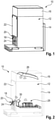
- a test system 10 that comprises a test chamber 12 that is encompassed by a housing 14 and a lid 16 which together delimit a space of the test chamber 12.
- the test system 10 further comprises an antenna assembly 18 that is connected with a connecting interface 20 of the test chamber 12.
- the connecting interface 20 is located at a wall 22 of the test chamber 12, which is part of the housing 14, particularly a side wall.
- an opening 24 is provided that is located next to the connecting interface 20 via which the antenna assembly 18 is connected with the test chamber 12 in a mechanical manner.
- the test chamber 12 has an opening 24 that is sealed by the antenna assembly 18 in the mounted state of the test system 10 that is shown in Figure 1 .
- test system 10 of Figure 1 is shown in a partially transparent manner since the housing 14 and the lid 16 are illustrated partially transparent, thereby providing an insight into the test chamber 12.
- a reflector 26 as well as a test location 28 are provided within the test chamber 12 which are encompassed via the housing 14 and the lid 16. Particularly, the reflector 26 is connected with the lid 16 such that the reflector 26 is orientated in a defined manner when the lid 16 is placed on the housing 14, namely in the mounted state of the test system 10.
- a signal path is established between the antenna assembly 18 and the test location 28 via the reflector 26, wherein the antenna assembly 18 is located in the focal point of the reflector 26.
- the respective signal path is illustrated by the respective symbols in Figure 2 .
- a shielding member 30 is provided that is located between the antenna assembly 18 and the test location 28. Hence, the shielding member 30 ensures that a device under test located at the test location 28 only receives signals from a dedicated direction, namely via the reflector 26.
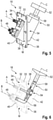
- the antenna assembly 18 according to a first embodiment is shown in Figure 4 in more detail.
- the antenna assembly 18 comprises a feedthrough part 32 that is established by a feedthrough plate 33 having a first side 34 as well a second side 36 opposite to the first side 34.
- the antenna assembly 18 has a multiplexing part 38 that is partially integrated within the feedthrough part 32 as shown in Figure 4 , particularly within the feedthrough plate 33.
- the multiplexing part 38 has a first portion 40 that is associated with the first side 34 of the feedthrough part 32, particularly the feedthrough plate 33. Further, the multiplexing part 38 has a second portion 42 that is associated with the second side 36 of the feedthrough part 32, particularly the feedthrough plate 33.
- the multiplexing part 38 extends through the feedthrough part 32, namely the feedthrough plate 33, as illustrated in Figure 4 .
- the antenna assembly 18 is connected with the test chamber 12, particularly the housing 14 having the opening 24, via its feedthrough part 32.
- the mechanical connection is established via the feedthrough plate 33 that has several holes 44 through which screws and/or bolts may extend in order to interact with holes provided in the test chamber 12, particularly the housing 14, within the connecting interface 20.
- the antenna assembly 18 can be connected to the test chamber 12 via the feedthrough part 32, particularly the feedthrough plate 33, which blocks and seals the opening 24 provided in the housing 14 accordingly.
- the antenna assembly 18 generally ensures that signals can be provided from the exterior, for instance an externally located signal generator, that are used within the test chamber 12 for testing the device under test that is located on the testing location 28.
- the antenna assembly 18 has at least two waveguide inputs 46, 48 that are associated with the first portion 40 of the multiplexing part 38.
- the waveguide inputs 46, 48 are associated with the exterior such that they can be accessed by the user in the mounted state easily.
- the antenna assembly 18 has a single waveguide output 50 that is associated with the second portion 42 of the multiplexing part 38, which faces the interior of the test chamber 12.
- the waveguide inputs 46, 48 are located externally, whereas the single waveguide output 50 is located within the test chamber 12.
- the first waveguide input 46 is orientated in parallel with the single waveguide output 50.
- the waveguide inputs 46, 48 are orientated in a perpendicular manner with respect to each other.
- an antenna 52 is connected with the single waveguide output 50 of the antenna assembly 18.
- the waveguide inputs 46, 48 are right-angled ones since they project from a side of the multiplexing part 38 which faces towards the exterior in a substantially perpendicular manner, namely in a right angle.
- the waveguide inputs 46, 48 can be used in combination with the multiplexing part 38 such that horizontally polarized signals as well as vertically polarized signals are multiplexed by the multiplexing part 38 in order to generate a circularly polarized signal that is outputted via the single waveguide output 50 and the antenna 52 connected thereto.
- the multiplexing part 38 may comprise an orthomode transducer 54.
- the multiplexing part 38 is established by or rather consists of the orthomode transducer 54 since orthogonally polarized signals, namely orthogonal modes, can be combined by means of the orthomode transducer 54.
- the waveguide inputs 46, 48 are directly connected with the multiplexing part 38, which in turn is directly connected with the single waveguide output 50. Hence, the respective components are formed in an integral or rather monolithic manner.
- the multiplexing part 38 is integrated within the feedthrough part 32, particularly the feedthrough plate 33, such that no gaps are provided between the multiplexing part 38 and the feedthrough part 32.
- the multiplexing part 38 and the feedthrough part 32 are formed in one piece, namely by the same material within a single manufacturing step.
- the assembly that comprises the waveguide inputs 46, 48, the multiplexing part 38, the single waveguide output 50 as well as the feedthrough part 32 are integrally formed or rather manufactured in a monolithic manner.
- the multiplexing part 38 and the feedthrough part 32 may be connected with each other by welding.
- two separate parts may be provided that are connected with each other afterwards, thereby establishing the respective assembly.
- FIGs 5 and 6 a second embodiment of the antenna assembly 18 is shown that distinguishes from the one shown in Figure 4 in that the waveguide inputs 46, 48 are coplanar.
- the waveguide inputs 46, 48 are located at a common side of the multiplexing part 38 that is associated with the first side 34 of the feedthrough part 32.
- the single waveguide output 50 has a center axis C that is inclined with respect to the center axes A, B of the waveguide inputs 46, 48, particularly by a right angle.
- center axis C of the single waveguide output 50 is also inclined with respect to a main plane M of the feedthrough part 32, particularly the feedthrough plate 33, wherein the main plane M is parallel to the first side 34 or rather the second side 36. This is also shown in the embodiment of Figure 4 .
- FIG. 6 a partially transparent illustration is provided that shows the signal paths associated with the waveguide inputs 46, 48, the orthomode transducer 54 as well as the single waveguide output 50.
- Figure 6 shows that an internal bent portion 56 is provided which has an angle of 90°.
- the internal bent portion 56 is interconnected between one of the waveguide inputs 46, 48 and the orthomode transducer 54.
- an internal transition 58 is installed that generally provides a transition from a square waveguide to a circular waveguide or vice versa.
- the internal transition 58 is located between the single waveguide output 50 having a square waveguide interface and the antenna 52 having a circular waveguide interface. Accordingly, the internal transition 58 ensures that the antenna 52 can be connected with the single waveguide output 50 even though differently shaped waveguide interfaces are provided.
- the internal transition 58 is an optional component that depends on the respective interface of the antenna 52 used for being connected with the single waveguide output 50.
- the internal transition 58 may also be a transition from a circular waveguide to a square waveguide provided that the single waveguide output 50 has a circular interface, whereas the antenna 52 has a square interface.
- the internal transition 58 may be located between the orthomode transducer 54 and the single waveguide output 50 in order to provide a transition between these components. Then, the internal transition 58 may relate to an integrated one.
- the internal transition 58 corresponds to an adapter that is used to adapt the respective kind of interfaces.
- the multiplexing part 38 may be integrated within the feedthrough part 32 such that the multiplexing part 38 and the feedthrough part 32 are formed in one piece or rather in a monolithic manner. For instance, a certain structure may be milled, thereby establishing the integration of the multiplexing part 38 within the feedthrough part 32.
- the antenna assembly 18 ensures low path loss due to the integration of the multiplexing part 38 into the feedthrough part 32.
- test system 10 is less complex since the antenna assembly 18 provides several functions in a combined manner.
- an easy feed switching namely a manual one
- the antenna assembly 18 since two waveguide inputs 46, 48 are provided at an external side of the antenna assembly 18 in its mounted state. Accordingly, the two waveguide inputs 46, 48 are associated with a side of the feedthrough part 32 that can be accessed from the exterior when the antenna assembly 18 is installed, namely connected with the test chamber 12.
Landscapes
- Physics & Mathematics (AREA)
- General Physics & Mathematics (AREA)
- Electromagnetism (AREA)
- Engineering & Computer Science (AREA)
- Computer Networks & Wireless Communication (AREA)
- General Engineering & Computer Science (AREA)
- Waveguide Aerials (AREA)
Abstract
Description
- The invention relates to an antenna assembly for a test system. Further, the invention relates to a test system for testing a device under test as well as a method of establishing a test system for testing a device under test.
- In the state of the art, it is known to test several different devices under test (DUTs) by means of a test system that comprises a test chamber in which the respective device under test is placed for testing purposes. These test systems relate to so-called compact antenna test ranges (CATR) since far-field characteristics of the device under test can be tested even though the test chamber has small dimensions. The test system comprises at least one feed antenna that is used for testing the device under test, wherein the feed antenna receives test signals that are converted into radio waves by the antenna, which are used to test the device under test. Typically, the respective test signals are generated externally by means of a signal generator. Thus, it is required to forward the respective test signals generated to the feed antenna that is located within the test chamber. For this purpose, a feedthrough is provided in the housing of the test chamber. The feedthrough is connected with the antenna by cables that are located within the test chamber, particularly at a bottom or in a shielded manner.
- The respective feed antennas may be established as dual-polarized antennas that are enabled to process horizontally polarized signals as well as vertically polarized signals, namely orthogonally polarized signals. Hence, a so-called orthomode transducer (OMT) is provided that is connected with the feed antenna. The orthomode transducer is a waveguide component that is also called polarization duplexer since it serves to combine or to separate two orthogonally polarized signals, which may be provided by respective signal paths. Accordingly, the orthomode transducer is typically interconnected between the feedthrough and the antenna.
- However, the test systems known in the state of the art, particularly the arrangement of the individual components, are not suitable for very small chambers, particularly in relation to the size of the quite zone used for testing the device under test.
- Accordingly, there is need for a test system that is suitable for small test chambers, particularly with respect to the size of the quite zone.
- The invention provides an antenna assembly for a test system, wherein the antenna assembly comprises a feedthrough part, two waveguide inputs, a single waveguide output as well as a multiplexing part that is interconnected between the two waveguide inputs and the single waveguide output. The multiplexing part is integrated within the feedthrough part at least partly.
- The invention is based on the idea to at least partly integrate the multiplexing part within the feedthrough part that provides the interface for interconnecting a feed antenna of the test system with the respective cables or lines that provide the test signals generated by an external signal generator. Accordingly, it is no more necessary to connect the multiplexing part with the feedthrough via cables. Since the multiplexing part is directly integrated into the feedthrough part, no gaps between the multiplexing part and the feedthrough part occur. Put differently, the space required between the multiplexing part and the feedthrough part is minimized, thereby ensuring that relatively small test chambers can be used for testing the device under test, particularly compared to the size of the quite zone established for testing purposes.
- In general, the multiplexing part can be used for combining different signals, particularly differently polarized signals such as orthogonally polarized signals. The different signals may be forwarded to the antenna assembly by the respective waveguide inputs that can be connected with cables or lines originating from the signal generator.
- Further, the multiplexing part can be used for separating different signal portions of a signal processed, particularly differently polarized signal portions such as orthogonally polarized signal portions. The different signal portions may be forwarded to an externally located signal analyzer by the respective waveguide inputs. Hence, the waveguide inputs are used to forward signals to the signal analyzer.
- Generally, the waveguide inputs as well as the single waveguide output may be used in a bidirectional manner, which means that they can be used in both transmission directions. In fact, this depends on the operation mode of the antenna assembly. When signals are transmitted to the device under test, the test signals are forwarded to the waveguide inputs that process the signals in order to output radio waves to the device under test via the single waveguide output. When signals are transmitted by the device under test, the single waveguide output receives the signals which are processed and forwarded to the waveguide inputs.
- Moreover, the antenna assembly ensures low path loss due to the integration of the multiplexing part into the feedthrough part. Furthermore, the entire test system is less complex compared to the arrangement known in the state of the art since the antenna assembly according to the invention provides several functions in a combined manner.
- In addition, an easy feed switching, namely a manual one, can be ensured by the antenna assembly due to the fact that two waveguide inputs are provided at an external side such that the two waveguide inputs are associated with a side of the feedthrough part that can be accessed from the outside when the antenna assembly is installed, namely in the mounted state.
- An aspect provides that the multiplexing part is integrated within the feedthrough by milling and/or welding. The multiplexing part may be provided at least partially by material of the feedthrough part. For instance, a respective structure is milled within the material of the feedthrough part such that the structure is used for multiplexing. In an alternative, the multiplexing part and the feedthrough part are separately manufactured parts that are integrated with each other by welding. Nevertheless, the feedthrough part contributes to the multiplexing part at the respective interface and vice versa.
- In an example, the multiplexing part and the feedthrough part are formed in one piece. Hence, the multiplexing part may be integrated within the feedthrough part entirely, namely during the manufacturing process of the antenna assembly. In other words, the multiplexing part and the feedthrough part are together formed as an integrally formed assembly, also called a monolithic assembly. For instance, the feedthrough part and the multiplexing part are moulded or rather casted together in a single manufacturing step, thereby establishing the integrally formed or rather monolithic assembly.
- The multiplexing part may comprise an orthomode transducer (OMT). Particularly, the multiplexing part is established as an orthomode transducer. The two waveguide inputs are both connected with the multiplexing part such that the signals forwarded by the two waveguide inputs are multiplexed with each other in an orthogonal manner.
- Generally, the orthomode transducer is a 3-port waveguide component that is used to separate horizontally polarized signal portions and vertically polarized signal portions from a circularly polarized signal or rather to combine horizontally polarized signals and vertically polarized signals to a circularly polarized signal.
- At least one of the two waveguide inputs may be assigned to an internal bent portion, particularly by an angle of 90°, such that both waveguide inputs are coplanar. The respective waveguide inputs are located at a common side that can be accessed by the user of the test system easily. Furthermore, the signals processed by the waveguide inputs and forwarded to the multiplexing part can be multiplexed in an orthogonal manner. A horizontally polarized signal and a vertically polarized signal may be provided at the respective inputs which are combined to a circular polarized signal.
- Another aspect provides that the single waveguide output has a center axis that is inclined with respect to the center axes of the two waveguide inputs and/or the feedthrough part. The center axis of the single waveguide output may coincide with an antenna aperture of an antenna to be connected with the single waveguide output, which corresponds to the direction of the main lobe of the radiation pattern provided by the respective antenna. Since the axes are inclined with respect to each other, the connection of feed lines to the waveguide inputs is independent from an internal arrangement of the antenna. Hence, the overall handling is simplified.
- Since the center axis of the single waveguide output is inclined with respect to the feedthrough part, particularly a main plane of the feedthrough part, it is ensured that signals emitted by the antenna connected with the antenna assembly can be transmitted towards a reflector located within the test chamber. The inclination angle is different to 0° and 90° with respect to a side wall of the test chamber, particularly the adjacent side wall.
- According to a further aspect, at least one of the two waveguide inputs and the single waveguide output are orientated in parallel with respect to each other, in particular wherein the respective waveguide input is right-angled. This relates to a specific embodiment in which the center axes of one of the waveguide inputs, particularly the right-angled one, and the single waveguide output are coplanar with respect to each other even though they are associated with different sides of the feedthrough part, namely the one associated with an exterior and the one associated with an interior. The waveguide inputs may be located at different planes in this specific embodiment, particularly in a perpendicular manner. However, the multiplexing part ensures that the signals provided via the two waveguide inputs are superimposed or rather multiplexed in an orthogonal manner.
- Generally, the feedthrough part may comprise a feedthrough plate, wherein the multiplexing part extends through the feedthrough plate such that the multiplexing part has a first portion associated with a first side of the feedthrough plate and a second portion associated with a second side of the feedthrough plate, which is opposite to the first side. In fact, the feedthrough part can be established by the feedthrough plate entirely. Put differently, the feedthrough part may consist of the feedthrough plate. Hence, the multiplexing part is integrated within the feedthrough plate, particularly in an inclined manner with regard to a main plane of the feedthrough plate. The feedthrough plate defines the main plane appropriately. The main plane of the feedthrough plate is parallel to the first side and/or the second side of the feedthrough plate which is opposite to the first side.
- In general, the multiplexing part extends through the feedthrough plate, wherein the multiplexing part may be located with its center in a plane that corresponds to the center plane of the feedthrough plate. In other words, the center plane encompasses the axis of symmetry of the feedthrough plate. Alternatively, the multiplexing part may extend through the feedthrough plate in a non-symmetric manner, thereby establishing a main portion (concerning the volume) that is associated with the first portion or the second portion. This may inter alia depend on the arrangement of the waveguide inputs at the multiplexing part.
- In general, the waveguide inputs are directly connected with the multiplexing part, namely the (integrated) orthomode transducer. Further, the single waveguide output is also directly connected with the multiplexing part, namely the (integrated) orthomode transducer. Thus, the multiplexing part is interconnected between the waveguide inputs and the single waveguide output. Accordingly, the waveguide inputs, the multiplexing part and the single waveguide output together establish a monolithic assembly, namely an integrally formed assembly.
- The feedthrough part, namely the feedthrough plate, surrounds the multiplexing part at least partly, thereby including or rather accommodating the multiplexing part in parts.
- In any case, the assembly, namely the waveguide inputs, the multiplexing part, the single waveguide output as well as the feedthrough part, may be established by in an integrally formed or rather monolithic manner, thereby providing the interfaces for connecting feed lines as well as the antenna. Simultaneously, the assembly provides the multiplexing functionality as well as the feedthrough functionality.
- The single waveguide output may be a circular one or a square one. Thus, the antenna to be connected with the single waveguide output may have a circularly shaped input interface or rather a squared input interface.
- Another aspect provides that an antenna is provided that is connected with the single waveguide output. The respective antenna corresponds to the feed antenna that is used for testing the device under test by the test system. The antenna is a circular horn antenna or a square horn antenna. Depending on the respective input interface of the antenna, the single waveguide output may provide a corresponding interface.
- Typically, the antenna is provided as a separate part with respect to the assembly that comprises the waveguide inputs, the multiplexing part, the single waveguide output as well as the feedthrough part. Accordingly, the entire antenna assembly that comprises the antenna may be made of two parts, namely the antenna and the integrally formed remainder that comprises waveguide inputs, the multiplexing part, the single waveguide output as well as the feedthrough part.
- In addition, at least one internal transition from square waveguides to a circular waveguide or from circular waveguide to square waveguide is provided. This means that the single waveguide output may be assigned to a square output interface whereas the respective antenna has a circular input interface. The intern transition ensures that the respective antenna can be connected with the multiplexing part via the internal transition.
- Alternatively, the internal transition may be provided between the multiplexing part and the single waveguide output, thereby transforming the respective shape between the multiplexing part and the single waveguide output. The internal transition may relate to an integrated one.
- Furthermore, the invention provides a test system for testing a device under test. The test system comprises a test chamber with an opening and the antenna assembly described above. The feedthrough part of the antenna assembly is located in the area of the opening such that the opening is sealed by the feedthrough part, in particular wherein the feedthrough part provides a portion of the wall of the test chamber. Therefore, separately formed feedthrough means are no more necessary since the antenna assembly itself provides the feedthrough part that is used for forwarding test signals from an exterior into the test chamber that can be used for testing the device under test in appropriate manner. The test chamber has an opening that is used for receiving the antenna assembly, particularly its feedthrough part. In a mounted state of the test system, the opening is sealed by the feedthrough part of the antenna assembly Further, the antenna assembly is connected with the test chamber in the mounted state via a connecting interface of the test chamber.
- An aspect provides that a reflector is located within the test chamber via which a signal path is established between an antenna connected with the single waveguide output of the antenna assembly and a test location for device under test. A quite zone is established at the test location, which is used for testing the device under test under defined conditions. Typically, the antenna is placed at the focal point of the respective reflector at a specific angle that is used for testing the device under test.
- The invention further provides a method of establishing a test system for testing a device under test. The method comprises the following steps:
- Providing an antenna assembly as described above,
- Connecting the antenna assembly via its feedthrough part with a connecting interface of a test chamber, and
- Connecting an antenna with the single waveguide output of the antenna assembly.
- Accordingly, the test system is established that can be used for testing the device under test. The test system corresponds to a compact antenna test range (CATR) that is used for testing the device under test over-the-air (OTA). The antenna assembly having the feedthrough part ensures that the test chamber is sealed by blocking and therefore sealing the opening within the test chamber.
- In fact, the feedthrough part may be connected to the connecting interface mechanically, particularly via bolts and/or screws. The mechanical connection may be done via the outer surface of the test chamber such that the mechanical connection may be established in an easy manner since the external sides of the test chamber can be accessed easily by a user of the test system.
- The foregoing aspects and many of the attendant advantages of the claimed subject matter will become more readily appreciated as the same become better understood by reference to the following detailed description, when taken in conjunction with the accompanying drawings. In the drawings,
-
Figure 1 shows a test system according to the invention, -
Figure 2 shows the test system ofFigure 1 in a partially transparent manner, -
Figure 3 shows a detail ofFigure 2 , -
Figure 4 shows an antenna assembly according to a first embodiment of the invention, -
Figure 5 shows an antenna assembly according to a second embodiment of the invention, and -
Figure 6 shows the antenna assembly ofFigure 5 in a partially transparent manner. - The detailed description set forth below in connection with the appended drawings, where like numerals reference like elements, is intended as a description of various embodiments of the disclosed subject matter and is not intended to represent the only embodiments. Each embodiment described in this disclosure is provided merely as an example or illustration and should not be construed as preferred or advantageous over other embodiments. The illustrative examples provided herein are not intended to be exhaustive or to limit the claimed subject matter to the precise forms disclosed.
- For the purposes of the present disclosure, the phrase "at least one of A, B, and C", for example, means (A), (B), (C), (A and B), (A and C), (B and C), or (A, B, and C), including all further possible permutations when greater than three elements are listed. In other words, the term "at least one of A and B" generally means "A and/or B", namely "A" alone, "B" alone or "A and B".
- In
Figure 1 , atest system 10 is shown that comprises atest chamber 12 that is encompassed by ahousing 14 and alid 16 which together delimit a space of thetest chamber 12. - The
test system 10 further comprises anantenna assembly 18 that is connected with a connectinginterface 20 of thetest chamber 12. The connectinginterface 20 is located at awall 22 of thetest chamber 12, which is part of thehousing 14, particularly a side wall. - In the
wall 22, anopening 24 is provided that is located next to the connectinginterface 20 via which theantenna assembly 18 is connected with thetest chamber 12 in a mechanical manner. In other words, thetest chamber 12 has anopening 24 that is sealed by theantenna assembly 18 in the mounted state of thetest system 10 that is shown inFigure 1 . - In
Figure 2 , thetest system 10 ofFigure 1 is shown in a partially transparent manner since thehousing 14 and thelid 16 are illustrated partially transparent, thereby providing an insight into thetest chamber 12. - It is shown in
Figure 2 that areflector 26 as well as atest location 28 are provided within thetest chamber 12 which are encompassed via thehousing 14 and thelid 16. Particularly, thereflector 26 is connected with thelid 16 such that thereflector 26 is orientated in a defined manner when thelid 16 is placed on thehousing 14, namely in the mounted state of thetest system 10. - Generally, a signal path is established between the
antenna assembly 18 and thetest location 28 via thereflector 26, wherein theantenna assembly 18 is located in the focal point of thereflector 26. The respective signal path is illustrated by the respective symbols inFigure 2 . - In addition, a shielding
member 30 is provided that is located between theantenna assembly 18 and thetest location 28. Hence, the shieldingmember 30 ensures that a device under test located at thetest location 28 only receives signals from a dedicated direction, namely via thereflector 26. - In
Figure 3 , theantenna assembly 18, the shieldingmember 30 as well as thetest location 28 are shown in more detail. It becomes obvious that the shieldingmember 30 is located in the direct way between theantenna assembly 18 and thetest location 28. - The
antenna assembly 18 according to a first embodiment is shown inFigure 4 in more detail. - The
antenna assembly 18 comprises afeedthrough part 32 that is established by afeedthrough plate 33 having afirst side 34 as well asecond side 36 opposite to thefirst side 34. - In addition, the
antenna assembly 18 has a multiplexingpart 38 that is partially integrated within thefeedthrough part 32 as shown inFigure 4 , particularly within thefeedthrough plate 33. - Hence, the multiplexing
part 38 has afirst portion 40 that is associated with thefirst side 34 of thefeedthrough part 32, particularly thefeedthrough plate 33. Further, the multiplexingpart 38 has asecond portion 42 that is associated with thesecond side 36 of thefeedthrough part 32, particularly thefeedthrough plate 33. - In other words, the multiplexing
part 38 extends through thefeedthrough part 32, namely thefeedthrough plate 33, as illustrated inFigure 4 . - As shown in
Figures 1, 2 ,3 , theantenna assembly 18 is connected with thetest chamber 12, particularly thehousing 14 having theopening 24, via itsfeedthrough part 32. - In fact, the mechanical connection is established via the
feedthrough plate 33 that hasseveral holes 44 through which screws and/or bolts may extend in order to interact with holes provided in thetest chamber 12, particularly thehousing 14, within the connectinginterface 20. - Accordingly, the
antenna assembly 18 can be connected to thetest chamber 12 via thefeedthrough part 32, particularly thefeedthrough plate 33, which blocks and seals theopening 24 provided in thehousing 14 accordingly. - The
antenna assembly 18 generally ensures that signals can be provided from the exterior, for instance an externally located signal generator, that are used within thetest chamber 12 for testing the device under test that is located on thetesting location 28. - For this purpose, the
antenna assembly 18 has at least twowaveguide inputs first portion 40 of the multiplexingpart 38. Hence, thewaveguide inputs antenna assembly 18 has asingle waveguide output 50 that is associated with thesecond portion 42 of the multiplexingpart 38, which faces the interior of thetest chamber 12. - In the mounted state of the
antenna assembly 18 at thetest chamber 12, thewaveguide inputs single waveguide output 50 is located within thetest chamber 12. - In the shown embodiment, the
first waveguide input 46 is orientated in parallel with thesingle waveguide output 50. - The
waveguide inputs - Moreover, an
antenna 52 is connected with thesingle waveguide output 50 of theantenna assembly 18. - In the shown embodiment, the
waveguide inputs part 38 which faces towards the exterior in a substantially perpendicular manner, namely in a right angle. - The
waveguide inputs part 38 such that horizontally polarized signals as well as vertically polarized signals are multiplexed by the multiplexingpart 38 in order to generate a circularly polarized signal that is outputted via thesingle waveguide output 50 and theantenna 52 connected thereto. - Accordingly, the multiplexing
part 38 may comprise anorthomode transducer 54. Particularly, the multiplexingpart 38 is established by or rather consists of theorthomode transducer 54 since orthogonally polarized signals, namely orthogonal modes, can be combined by means of theorthomode transducer 54. - The
waveguide inputs part 38, which in turn is directly connected with thesingle waveguide output 50. Hence, the respective components are formed in an integral or rather monolithic manner. - In addition, the multiplexing
part 38 is integrated within thefeedthrough part 32, particularly thefeedthrough plate 33, such that no gaps are provided between the multiplexingpart 38 and thefeedthrough part 32. For instance, the multiplexingpart 38 and thefeedthrough part 32 are formed in one piece, namely by the same material within a single manufacturing step. Hence, the assembly that comprises thewaveguide inputs part 38, thesingle waveguide output 50 as well as thefeedthrough part 32 are integrally formed or rather manufactured in a monolithic manner. - Alternatively, the multiplexing
part 38 and thefeedthrough part 32 may be connected with each other by welding. Hence, two separate parts may be provided that are connected with each other afterwards, thereby establishing the respective assembly. - In
Figures 5 and 6 , a second embodiment of theantenna assembly 18 is shown that distinguishes from the one shown inFigure 4 in that thewaveguide inputs - Hence, the
waveguide inputs part 38 that is associated with thefirst side 34 of thefeedthrough part 32. - Thus, the
single waveguide output 50 has a center axis C that is inclined with respect to the center axes A, B of thewaveguide inputs - In addition, the center axis C of the
single waveguide output 50 is also inclined with respect to a main plane M of thefeedthrough part 32, particularly thefeedthrough plate 33, wherein the main plane M is parallel to thefirst side 34 or rather thesecond side 36. This is also shown in the embodiment ofFigure 4 . - In
Figure 6 , a partially transparent illustration is provided that shows the signal paths associated with thewaveguide inputs orthomode transducer 54 as well as thesingle waveguide output 50. - Moreover,
Figure 6 shows that an internalbent portion 56 is provided which has an angle of 90°. The internalbent portion 56 is interconnected between one of thewaveguide inputs orthomode transducer 54. - In addition, an
internal transition 58 is installed that generally provides a transition from a square waveguide to a circular waveguide or vice versa. - In the shown embodiment, the
internal transition 58 is located between thesingle waveguide output 50 having a square waveguide interface and theantenna 52 having a circular waveguide interface. Accordingly, theinternal transition 58 ensures that theantenna 52 can be connected with thesingle waveguide output 50 even though differently shaped waveguide interfaces are provided. - The
internal transition 58 is an optional component that depends on the respective interface of theantenna 52 used for being connected with thesingle waveguide output 50. - Of course, the
internal transition 58 may also be a transition from a circular waveguide to a square waveguide provided that thesingle waveguide output 50 has a circular interface, whereas theantenna 52 has a square interface. - Moreover, the
internal transition 58 may be located between theorthomode transducer 54 and thesingle waveguide output 50 in order to provide a transition between these components. Then, theinternal transition 58 may relate to an integrated one. - Accordingly, the
internal transition 58 corresponds to an adapter that is used to adapt the respective kind of interfaces. - In general, the multiplexing
part 38 may be integrated within thefeedthrough part 32 such that the multiplexingpart 38 and thefeedthrough part 32 are formed in one piece or rather in a monolithic manner. For instance, a certain structure may be milled, thereby establishing the integration of the multiplexingpart 38 within thefeedthrough part 32. - Alternatively, two separate parts are provided that are welded together in order to establish the partly integration. However, no gaps occur between the multiplexing
part 38 and thefeedthrough part 32, thereby ensuring that the overall size is reduced accordingly. - The
antenna assembly 18 ensures low path loss due to the integration of the multiplexingpart 38 into thefeedthrough part 32. - Furthermore, the
entire test system 10 is less complex since theantenna assembly 18 provides several functions in a combined manner. - In addition, an easy feed switching, namely a manual one, is ensured by the
antenna assembly 18 since twowaveguide inputs antenna assembly 18 in its mounted state. Accordingly, the twowaveguide inputs feedthrough part 32 that can be accessed from the exterior when theantenna assembly 18 is installed, namely connected with thetest chamber 12.
Claims (15)
- An antenna assembly for a test system (10), wherein the antenna assembly (18) comprises a feedthrough part (32), two waveguide inputs (46, 48), a single waveguide output (50) as well as a multiplexing part (38) that is interconnected between the two waveguide inputs (46, 48) and the single waveguide output (50), and wherein the multiplexing part (38) is integrated within the feedthrough part (32) at least partly.
- The antenna assembly according to claim 1, characterized in that the multiplexing part (38) is integrated within the feedthrough part (32) by milling and/or welding.
- The antenna assembly according to claim 1 or 2, characterized in that the multiplexing part (38) and the feedthrough part (32) are formed in one piece.
- The antenna assembly according to any of the preceding claims, characterized in that the multiplexing part (38) comprises an orthomode transducer (54).
- The antenna assembly according to any of the preceding claims, characterized in that at least one of the two waveguide inputs (46, 48) is assigned to an internal bent portion (56), particularly by an angle of 90°, such that both waveguide inputs (46, 48) are coplanar.
- The antenna assembly according to any of the preceding claims, characterized in that the single waveguide output (50) has a center axis (C) that is inclined with respect to the center axes (A, B) of the two waveguide inputs (46, 48) and/or the feedthrough part (32).
- The antenna assembly according to any of the preceding claims, characterized in that at least one of the two waveguide inputs (46, 48) and the single waveguide output (50) are orientated in parallel with respect to each other, in particular wherein the respective waveguide input (46, 48) is right-angled.
- The antenna assembly according to any of the preceding claims, characterized in that the feedthrough part (32) comprises a feedthrough plate (33), wherein the multiplexing part (38) extends through the feedthrough plate (33) such that the multiplexing part (38) has a first portion (40) associated with a first side (34) of the feedthrough plate (33) and a second portion (42) associated with a second side (36) of the feedthrough plate (33), which is opposite to the first side (34).
- The antenna assembly according to any of the preceding claims, characterized in that the single waveguide output (50) is a circular one or a square one.
- The antenna assembly according to any of the preceding claims, characterized in that an antenna (52) is provided that is connected with the single waveguide output (50), in particular wherein the antenna (52) is a circular horn antenna or a square horn antenna.
- The antenna assembly according to any of the preceding claims, characterized in that at least one internal transition (58) from square waveguide to circular waveguide or from circular waveguide to square waveguide is provided, in particular wherein the at least one internal transition (58) is provided by the multiplexing part (38).
- A test system for testing a device under test, wherein the test system (10) comprises a test chamber (12) with an opening (24) and the antenna assembly (18) according to any of the preceding claims, wherein the feedthrough part (32) of the antenna assembly (18) is located in the area of the opening (24) such that the opening (24) is sealed by the feedthrough part, (32) in particular wherein the feedthrough part (32) provides a portion of the wall (22) of the test chamber (16).
- The test system according to claim 12, characterized in that a reflector (26) is located within the test chamber (16) via which a signal path is established between an antenna (52) connected with the single waveguide output (50) of the antenna assembly (18) and a test location (28) for a device under test.
- A method of establishing a test system (10) for testing a device under test, wherein the method comprises the following steps:- Providing an antenna assembly (18) according to any of claims 1 to 11,- Connecting the antenna assembly (18) via its feedthrough part (32) with a connecting interface (20) of a test chamber (12), and- Connecting an antenna (52) with the single waveguide output (50) of the antenna assembly (18).
- The method according to claim 14, characterized in that the feedthrough part (32) is connected to the connecting interface (20) mechanically, particularly via bolts and/or screws.
Priority Applications (3)
| Application Number | Priority Date | Filing Date | Title |
|---|---|---|---|
| EP20188379.0A EP3945628B1 (en) | 2020-07-29 | 2020-07-29 | Antenna assembly, test system and method of establishing a test system |
| CN202110744730.2A CN114069210A (en) | 2020-07-29 | 2021-07-01 | Antenna assembly, test system and method for establishing test system |
| US17/365,726 US11789068B2 (en) | 2020-07-29 | 2021-07-01 | Antenna assembly, test system and method of establishing a test system |
Applications Claiming Priority (1)
| Application Number | Priority Date | Filing Date | Title |
|---|---|---|---|
| EP20188379.0A EP3945628B1 (en) | 2020-07-29 | 2020-07-29 | Antenna assembly, test system and method of establishing a test system |
Publications (2)
| Publication Number | Publication Date |
|---|---|
| EP3945628A1 true EP3945628A1 (en) | 2022-02-02 |
| EP3945628B1 EP3945628B1 (en) | 2026-03-11 |
Family
ID=71846282
Family Applications (1)
| Application Number | Title | Priority Date | Filing Date |
|---|---|---|---|
| EP20188379.0A Active EP3945628B1 (en) | 2020-07-29 | 2020-07-29 | Antenna assembly, test system and method of establishing a test system |
Country Status (3)
| Country | Link |
|---|---|
| US (1) | US11789068B2 (en) |
| EP (1) | EP3945628B1 (en) |
| CN (1) | CN114069210A (en) |
Cited By (1)
| Publication number | Priority date | Publication date | Assignee | Title |
|---|---|---|---|---|
| US11709191B1 (en) | 2022-04-29 | 2023-07-25 | Rohde & Schwarz Gmbh & Co. Kg | Compact antenna test range system and method for calibrating a compact antenna test range |
Families Citing this family (2)
| Publication number | Priority date | Publication date | Assignee | Title |
|---|---|---|---|---|
| US11474138B1 (en) * | 2021-10-19 | 2022-10-18 | Rohde & Schwarz Gmbh & Co. Kg | Over-the-air measurement system |
| WO2024162963A1 (en) * | 2023-02-01 | 2024-08-08 | ETS-Lindgren Inc. | Distributions of boundary array test electronics |
Citations (3)
| Publication number | Priority date | Publication date | Assignee | Title |
|---|---|---|---|---|
| US6087908A (en) * | 1998-09-11 | 2000-07-11 | Channel Master Llc | Planar ortho-mode transducer |
| US20090302971A1 (en) * | 2006-02-03 | 2009-12-10 | Uwe Rosenberg | Ortho-Mode Transducer |
| US20200177289A1 (en) * | 2018-11-29 | 2020-06-04 | Anritsu Corporation | Antenna apparatus and measurement method |
Family Cites Families (5)
| Publication number | Priority date | Publication date | Assignee | Title |
|---|---|---|---|---|
| US3639863A (en) * | 1970-06-22 | 1972-02-01 | Raytheon Co | Radiofrequency feedthrough |
| JPS59178002A (en) * | 1983-03-29 | 1984-10-09 | Radio Res Lab | Circularly polarized wave antenna |
| GB2434923A (en) * | 2006-02-03 | 2007-08-08 | Ericsson Telefon Ab L M | Antenna feed device using two separate L-shaped waveguides to give an overall T-shape |
| WO2014035824A1 (en) * | 2012-08-27 | 2014-03-06 | Kvh Industries, Inc. | Antenna system with integrated distributed transceivers |
| EP3546958B1 (en) * | 2018-03-28 | 2022-11-23 | Rohde & Schwarz GmbH & Co. KG | Measurement system and method for testing a device under test |
-
2020
- 2020-07-29 EP EP20188379.0A patent/EP3945628B1/en active Active
-
2021
- 2021-07-01 CN CN202110744730.2A patent/CN114069210A/en active Pending
- 2021-07-01 US US17/365,726 patent/US11789068B2/en active Active
Patent Citations (3)
| Publication number | Priority date | Publication date | Assignee | Title |
|---|---|---|---|---|
| US6087908A (en) * | 1998-09-11 | 2000-07-11 | Channel Master Llc | Planar ortho-mode transducer |
| US20090302971A1 (en) * | 2006-02-03 | 2009-12-10 | Uwe Rosenberg | Ortho-Mode Transducer |
| US20200177289A1 (en) * | 2018-11-29 | 2020-06-04 | Anritsu Corporation | Antenna apparatus and measurement method |
Cited By (1)
| Publication number | Priority date | Publication date | Assignee | Title |
|---|---|---|---|---|
| US11709191B1 (en) | 2022-04-29 | 2023-07-25 | Rohde & Schwarz Gmbh & Co. Kg | Compact antenna test range system and method for calibrating a compact antenna test range |
Also Published As
| Publication number | Publication date |
|---|---|
| US11789068B2 (en) | 2023-10-17 |
| US20220034961A1 (en) | 2022-02-03 |
| EP3945628B1 (en) | 2026-03-11 |
| CN114069210A (en) | 2022-02-18 |
Similar Documents
| Publication | Publication Date | Title |
|---|---|---|
| US11789068B2 (en) | Antenna assembly, test system and method of establishing a test system | |
| US9728863B2 (en) | Power splitter comprising a tee coupler in the e-plane, radiating array and antenna comprising such a radiating array | |
| US6281855B1 (en) | Monopulse antenna apparatus | |
| US7884768B2 (en) | Compact, dual-beam phased array antenna architecture | |
| US9478838B2 (en) | Orthomode coupler for an antenna system | |
| KR20130141580A (en) | Antenna system | |
| JP4035506B2 (en) | Frequency separation waveguide module with double circular polarization | |
| US9929471B2 (en) | Very compact TM01 mode extractor | |
| CA2659345A1 (en) | Compact orthomode transduction device optimized in the mesh plane, for an antenna | |
| CA2950993A1 (en) | Compact bipolarization excitation assembly for a radiating antenna element and compact array comprising at least four compact excitation assemblies | |
| US7095380B2 (en) | Antenna device | |
| CA2913372C (en) | Compact radiofrequency excitation module with integrated kinematics and compact biaxial antenna comprising at least one such compact module | |
| JP2008005461A (en) | Satellite signal converter, antenna device, and satellite broadcast receiver | |
| CN114243312A (en) | Multi-frequency feed network, TR module and phased array antenna | |
| CN115993489B (en) | Aerial measurement system | |
| CN110567556B (en) | Frequency modulation continuous wave radar level gauge for measuring material level in container | |
| US11474138B1 (en) | Over-the-air measurement system | |
| EP0148136B1 (en) | Monopulse feeder for two separated frequency bands | |
| US6384796B1 (en) | Antenna for radiating and receiving electromagnetic waves | |
| EP1168485A1 (en) | Microwave diplexer-module for separating high frequency transmission signals on the basis of their frequencies | |
| EP3282516B1 (en) | Waveguide transition structure for receiving satellite signals | |
| US12603407B2 (en) | Compact feed system with developable waveguide H-plane directional coupler | |
| EP0925714B1 (en) | Circular stripline package incorporating a low noise amplifier | |
| Ruggerini et al. | A Ku-Band Magnified Active Tx/Rx Multibeam Antenna Based on a Discrete Constrained Lens. Electronics 2021, 10, 2824 | |
| CN112993544A (en) | X-frequency band multi-polarization multi-channel microwave assembly |
Legal Events
| Date | Code | Title | Description |
|---|---|---|---|
| PUAI | Public reference made under article 153(3) epc to a published international application that has entered the european phase |
Free format text: ORIGINAL CODE: 0009012 |
|
| STAA | Information on the status of an ep patent application or granted ep patent |
Free format text: STATUS: THE APPLICATION HAS BEEN PUBLISHED |
|
| AK | Designated contracting states |
Kind code of ref document: A1 Designated state(s): AL AT BE BG CH CY CZ DE DK EE ES FI FR GB GR HR HU IE IS IT LI LT LU LV MC MK MT NL NO PL PT RO RS SE SI SK SM TR |
|
| STAA | Information on the status of an ep patent application or granted ep patent |
Free format text: STATUS: REQUEST FOR EXAMINATION WAS MADE |
|
| 17P | Request for examination filed |
Effective date: 20220322 |
|
| RBV | Designated contracting states (corrected) |
Designated state(s): AL AT BE BG CH CY CZ DE DK EE ES FI FR GB GR HR HU IE IS IT LI LT LU LV MC MK MT NL NO PL PT RO RS SE SI SK SM TR |
|
| P01 | Opt-out of the competence of the unified patent court (upc) registered |
Effective date: 20230525 |
|
| STAA | Information on the status of an ep patent application or granted ep patent |
Free format text: STATUS: EXAMINATION IS IN PROGRESS |
|
| 17Q | First examination report despatched |
Effective date: 20240820 |
|
| REG | Reference to a national code |
Ref country code: DE Ref legal event code: R079 Free format text: PREVIOUS MAIN CLASS: H01P0001161000 Ipc: G01R0029100000 Ref country code: DE Ref legal event code: R079 Ref document number: 602020068313 Country of ref document: DE Free format text: PREVIOUS MAIN CLASS: H01P0001161000 Ipc: G01R0029100000 |
|
| GRAP | Despatch of communication of intention to grant a patent |
Free format text: ORIGINAL CODE: EPIDOSNIGR1 |
|
| STAA | Information on the status of an ep patent application or granted ep patent |
Free format text: STATUS: GRANT OF PATENT IS INTENDED |
|
| RIC1 | Information provided on ipc code assigned before grant |
Ipc: G01R 29/10 20060101AFI20251201BHEP Ipc: G01R 29/08 20060101ALI20251201BHEP Ipc: H01P 1/161 20060101ALI20251201BHEP Ipc: H01Q 13/02 20060101ALN20251201BHEP |
|
| RIC1 | Information provided on ipc code assigned before grant |
Ipc: G01R 29/10 20060101AFI20251211BHEP Ipc: G01R 29/08 20060101ALI20251211BHEP Ipc: H01P 1/161 20060101ALI20251211BHEP Ipc: H01Q 13/02 20060101ALN20251211BHEP |
|
| INTG | Intention to grant announced |
Effective date: 20251218 |
|
| GRAS | Grant fee paid |
Free format text: ORIGINAL CODE: EPIDOSNIGR3 |
|
| GRAA | (expected) grant |
Free format text: ORIGINAL CODE: 0009210 |
|
| STAA | Information on the status of an ep patent application or granted ep patent |
Free format text: STATUS: THE PATENT HAS BEEN GRANTED |
|
| AK | Designated contracting states |
Kind code of ref document: B1 Designated state(s): AL AT BE BG CY CZ DE DK EE ES FI FR GB GR HR HU IS IT LT LU LV MC MK MT NL NO PL PT RO RS SE SI SK SM TR |
|
| RBV | Designated contracting states (corrected) |
Designated state(s): AL AT BE BG CY CZ DE DK EE ES FI FR GB GR HR HU IS IT LT LU LV MC MK MT NL NO PL PT RO RS SE SI SK SM TR |
|
| REG | Reference to a national code |
Ref country code: GB Ref legal event code: FG4D |
|
| REG | Reference to a national code |
Ref country code: DE Ref legal event code: R096 Ref document number: 602020068313 Country of ref document: DE |
|
| PG25 | Lapsed in a contracting state [announced via postgrant information from national office to epo] |
Ref country code: RS Free format text: LAPSE BECAUSE OF FAILURE TO SUBMIT A TRANSLATION OF THE DESCRIPTION OR TO PAY THE FEE WITHIN THE PRESCRIBED TIME-LIMIT Effective date: 20260611 |
|
| PG25 | Lapsed in a contracting state [announced via postgrant information from national office to epo] |
Ref country code: ES Free format text: LAPSE BECAUSE OF FAILURE TO SUBMIT A TRANSLATION OF THE DESCRIPTION OR TO PAY THE FEE WITHIN THE PRESCRIBED TIME-LIMIT Effective date: 20260311 |
|
| PG25 | Lapsed in a contracting state [announced via postgrant information from national office to epo] |
Ref country code: GR Free format text: LAPSE BECAUSE OF FAILURE TO SUBMIT A TRANSLATION OF THE DESCRIPTION OR TO PAY THE FEE WITHIN THE PRESCRIBED TIME-LIMIT Effective date: 20260612 |
|
| REG | Reference to a national code |
Ref country code: LT Ref legal event code: MG9D |
|
| PG25 | Lapsed in a contracting state [announced via postgrant information from national office to epo] |
Ref country code: LT Free format text: LAPSE BECAUSE OF FAILURE TO SUBMIT A TRANSLATION OF THE DESCRIPTION OR TO PAY THE FEE WITHIN THE PRESCRIBED TIME-LIMIT Effective date: 20260311 |
|
| PG25 | Lapsed in a contracting state [announced via postgrant information from national office to epo] |
Ref country code: NO Free format text: LAPSE BECAUSE OF FAILURE TO SUBMIT A TRANSLATION OF THE DESCRIPTION OR TO PAY THE FEE WITHIN THE PRESCRIBED TIME-LIMIT Effective date: 20260611 |
|
| PG25 | Lapsed in a contracting state [announced via postgrant information from national office to epo] |
Ref country code: SE Free format text: LAPSE BECAUSE OF FAILURE TO SUBMIT A TRANSLATION OF THE DESCRIPTION OR TO PAY THE FEE WITHIN THE PRESCRIBED TIME-LIMIT Effective date: 20260311 Ref country code: FI Free format text: LAPSE BECAUSE OF FAILURE TO SUBMIT A TRANSLATION OF THE DESCRIPTION OR TO PAY THE FEE WITHIN THE PRESCRIBED TIME-LIMIT Effective date: 20260311 |
|
| REG | Reference to a national code |
Ref country code: NL Ref legal event code: MP Effective date: 20260311 |
|
| PG25 | Lapsed in a contracting state [announced via postgrant information from national office to epo] |
Ref country code: HR Free format text: LAPSE BECAUSE OF FAILURE TO SUBMIT A TRANSLATION OF THE DESCRIPTION OR TO PAY THE FEE WITHIN THE PRESCRIBED TIME-LIMIT Effective date: 20260311 |
|
| PG25 | Lapsed in a contracting state [announced via postgrant information from national office to epo] |
Ref country code: LV Free format text: LAPSE BECAUSE OF FAILURE TO SUBMIT A TRANSLATION OF THE DESCRIPTION OR TO PAY THE FEE WITHIN THE PRESCRIBED TIME-LIMIT Effective date: 20260311 |
|
| PG25 | Lapsed in a contracting state [announced via postgrant information from national office to epo] |
Ref country code: BG Free format text: LAPSE BECAUSE OF FAILURE TO SUBMIT A TRANSLATION OF THE DESCRIPTION OR TO PAY THE FEE WITHIN THE PRESCRIBED TIME-LIMIT Effective date: 20260311 |