EP3945575B1 - Lighting apparatus - Google Patents
Lighting apparatus Download PDFInfo
- Publication number
- EP3945575B1 EP3945575B1 EP21188162.8A EP21188162A EP3945575B1 EP 3945575 B1 EP3945575 B1 EP 3945575B1 EP 21188162 A EP21188162 A EP 21188162A EP 3945575 B1 EP3945575 B1 EP 3945575B1
- Authority
- EP
- European Patent Office
- Prior art keywords
- light
- led
- lens
- section
- lighting apparatus
- Prior art date
- Legal status (The legal status is an assumption and is not a legal conclusion. Google has not performed a legal analysis and makes no representation as to the accuracy of the status listed.)
- Active
Links
Images


Classifications
-
- F—MECHANICAL ENGINEERING; LIGHTING; HEATING; WEAPONS; BLASTING
- F21—LIGHTING
- F21V—FUNCTIONAL FEATURES OR DETAILS OF LIGHTING DEVICES OR SYSTEMS THEREOF; STRUCTURAL COMBINATIONS OF LIGHTING DEVICES WITH OTHER ARTICLES, NOT OTHERWISE PROVIDED FOR
- F21V5/00—Refractors for light sources
- F21V5/007—Array of lenses or refractors for a cluster of light sources, e.g. for arrangement of multiple light sources in one plane
-
- H—ELECTRICITY
- H10—SEMICONDUCTOR DEVICES; ELECTRIC SOLID-STATE DEVICES NOT OTHERWISE PROVIDED FOR
- H10H—INORGANIC LIGHT-EMITTING SEMICONDUCTOR DEVICES HAVING POTENTIAL BARRIERS
- H10H20/00—Individual inorganic light-emitting semiconductor devices having potential barriers, e.g. light-emitting diodes [LED]
- H10H20/80—Constructional details
- H10H20/85—Packages
- H10H20/8506—Containers
-
- F—MECHANICAL ENGINEERING; LIGHTING; HEATING; WEAPONS; BLASTING
- F21—LIGHTING
- F21V—FUNCTIONAL FEATURES OR DETAILS OF LIGHTING DEVICES OR SYSTEMS THEREOF; STRUCTURAL COMBINATIONS OF LIGHTING DEVICES WITH OTHER ARTICLES, NOT OTHERWISE PROVIDED FOR
- F21V19/00—Fastening of light sources or lamp holders
- F21V19/001—Fastening of light sources or lamp holders the light sources being semiconductors devices, e.g. LEDs
- F21V19/0015—Fastening arrangements intended to retain light sources
-
- F—MECHANICAL ENGINEERING; LIGHTING; HEATING; WEAPONS; BLASTING
- F21—LIGHTING
- F21V—FUNCTIONAL FEATURES OR DETAILS OF LIGHTING DEVICES OR SYSTEMS THEREOF; STRUCTURAL COMBINATIONS OF LIGHTING DEVICES WITH OTHER ARTICLES, NOT OTHERWISE PROVIDED FOR
- F21V19/00—Fastening of light sources or lamp holders
- F21V19/04—Fastening of light sources or lamp holders with provision for changing light source, e.g. turret
-
- F—MECHANICAL ENGINEERING; LIGHTING; HEATING; WEAPONS; BLASTING
- F21—LIGHTING
- F21V—FUNCTIONAL FEATURES OR DETAILS OF LIGHTING DEVICES OR SYSTEMS THEREOF; STRUCTURAL COMBINATIONS OF LIGHTING DEVICES WITH OTHER ARTICLES, NOT OTHERWISE PROVIDED FOR
- F21V23/00—Arrangement of electric circuit elements in or on lighting devices
- F21V23/003—Arrangement of electric circuit elements in or on lighting devices the elements being electronics drivers or controllers for operating the light source, e.g. for a LED array
-
- F—MECHANICAL ENGINEERING; LIGHTING; HEATING; WEAPONS; BLASTING
- F21—LIGHTING
- F21V—FUNCTIONAL FEATURES OR DETAILS OF LIGHTING DEVICES OR SYSTEMS THEREOF; STRUCTURAL COMBINATIONS OF LIGHTING DEVICES WITH OTHER ARTICLES, NOT OTHERWISE PROVIDED FOR
- F21V23/00—Arrangement of electric circuit elements in or on lighting devices
- F21V23/06—Arrangement of electric circuit elements in or on lighting devices the elements being coupling devices, e.g. connectors
-
- F—MECHANICAL ENGINEERING; LIGHTING; HEATING; WEAPONS; BLASTING
- F21—LIGHTING
- F21V—FUNCTIONAL FEATURES OR DETAILS OF LIGHTING DEVICES OR SYSTEMS THEREOF; STRUCTURAL COMBINATIONS OF LIGHTING DEVICES WITH OTHER ARTICLES, NOT OTHERWISE PROVIDED FOR
- F21V9/00—Elements for modifying spectral properties, polarisation or intensity of the light emitted, e.g. filters
- F21V9/30—Elements containing photoluminescent material distinct from or spaced from the light source
-
- H—ELECTRICITY
- H10—SEMICONDUCTOR DEVICES; ELECTRIC SOLID-STATE DEVICES NOT OTHERWISE PROVIDED FOR
- H10H—INORGANIC LIGHT-EMITTING SEMICONDUCTOR DEVICES HAVING POTENTIAL BARRIERS
- H10H20/00—Individual inorganic light-emitting semiconductor devices having potential barriers, e.g. light-emitting diodes [LED]
- H10H20/80—Constructional details
- H10H20/85—Packages
- H10H20/851—Wavelength conversion means
-
- H—ELECTRICITY
- H10—SEMICONDUCTOR DEVICES; ELECTRIC SOLID-STATE DEVICES NOT OTHERWISE PROVIDED FOR
- H10W—GENERIC PACKAGES, INTERCONNECTIONS, CONNECTORS OR OTHER CONSTRUCTIONAL DETAILS OF DEVICES COVERED BY CLASS H10
- H10W90/00—Package configurations
-
- F—MECHANICAL ENGINEERING; LIGHTING; HEATING; WEAPONS; BLASTING
- F21—LIGHTING
- F21Y—INDEXING SCHEME ASSOCIATED WITH SUBCLASSES F21K, F21L, F21S and F21V, RELATING TO THE FORM OR THE KIND OF THE LIGHT SOURCES OR OF THE COLOUR OF THE LIGHT EMITTED
- F21Y2115/00—Light-generating elements of semiconductor light sources
- F21Y2115/10—Light-emitting diodes [LED]
Definitions
- the present invention is related to a lighting apparatus, and more particularly related to a lighting apparatus with multiple LED packages.
- Fire provides light to bright up the darkness that have allowed human activities to continue into the darker and colder hour of the hour after sunset. Fire gives human beings the first form of light and heat to cook food, make tools, have heat to live through cold winter and lighting to see in the dark.
- Lighting is now not to be limited just for providing the light we need, but it is also for setting up the mood and atmosphere being created for an area. Proper lighting for an area needs a good combination of daylight conditions and artificial lights. There are many ways to improve lighting in a better cost and energy saving. LED lighting, a solid-state lamp that uses light-emitting diodes as the source of light, is a solution when it comes to energy-efficient lighting. LED lighting provides lower cost, energy saving and longer life span.
- the major use of the light emitting diodes is for illumination.
- the light emitting diodes is recently used in light bulb, light strip or light tube for a longer lifetime and a lower energy consumption of the light.
- the light emitting diodes shows a new type of illumination which brings more convenience to our lives.
- light emitting diode light may be often seen in the market with various forms and affordable prices.
- LEDs After the invention of LEDs, the neon indicator and incandescent lamps are gradually replaced.
- the cost of initial commercial LEDs was extremely high, making them rare to be applied for practical use.
- LEDs only illuminated red light at early stage. The brightness of the light only could be used as indicator for it was too dark to illuminate an area. Unlike modern LEDs which are bound in transparent plastic cases, LEDs in early stage were packed in metal cases.
- candles were made in China in about 200 BC from whale fat and rice paper wick. They were made from other materials through time, like tallow, spermaceti, colza oil and beeswax until the discovery of paraffin wax which made production of candles cheap and affordable to everyone. Wick was also improved over time that made from paper, cotton, hemp and flax with different times and ways of burning.
- candles are still here as decorative items and a light source in emergency situations. They are used for celebrations such as birthdays, religious rituals, for making atmosphere and as a decor.
- Illumination has been improved throughout the times. Even now, the lighting device we used today are still being improved. From the illumination of the sun to the time when human can control fire for providing illumination which changed human history, we have been improving the lighting source for a better efficiency and sense. From the invention of candle, gas lamp, electric carbon arc lamp, kerosene lamp, light bulb, fluorescent lamp to LED lamp, the improvement of illumination shows the necessity of light in human lives.
- Panel ight devices are widely used in various environment. Panel light devices usually have smaller thickness.
- EP3684143 A1 and US2019057954 A1 present prior art lighting devices with controllable color temperatures.
- a lighting apparatus includes a light source plate, multiple light modules and a driver.
- Multiple light modules are placed on the light source plate.
- Each light module includes a LED package and a lens.
- the LED package includes multiple sections.
- At least a LED unit is placed in each section.
- Each section has a pair of corresponding LED electrodes.
- the driver is electrically connected to the LED electrodes for supplying an adjustable ratio of separate driving currents to the LED electrodes to generate a required light parameter by mixing multiple lights emitted by the LED units disposed in the sections of the light modules.
- the lens has multiple lens areas for guiding lights of different sections in each light module to generate a mixed light via the lens.
- the LED package has a first section and a second section.
- a first LED unit is placed in the first section covered with a first fluorescent layer.
- a second LED unit is place in the second section covered with a second fluorescent layer.
- the first fluorescent layer and the second fluorescent layer have different compositions.
- the LED package has a package housing and a spacer wall.
- the spacer wall separates the first section and the second section.
- the packaging housing has tilt bases for respectively placing the first LED unit and the second LED unit so that lights of the first LED unit and the second LED unit overlaps more than 50 percent in the lens.
- the first LED unit has at least one first type LED chip and one second type LED chip.
- the second LED unit has at least one first type LED chip and one second type LED chip.
- the driver adjusts the adjustable ratio of separate driving currents to generate the required light parameter.
- the LED package has a circular external shape.
- the first section is semi-circular shape and the second section is semi-circular shape.
- the light module has an aligning structure for aligning the lens with the LED package.
- the lens has a convex external curve surface.
- the lens has a concave curve inner dome facing to the LED package.
- the lens has multiple micro lenses for guiding lights of different sections to generate the mixed light via the lens.
- the lens has a package connector for aligning and coupling the LED package.
- the light source plate has multiple grooves for placing multiple light strips, the multiple light modules are placed on the light strips.
- the lighting apparatus may also include a light passing cover connected to the light source plate forming a container for enclosing the multiple light modules.
- the light passing cover has multiple cover lenses corresponding to the multiple light strips.
- the light strips are detachable to be replaced from the light source plate.
- the lens has a plugging structure for plugging on the light strip.
- the LED package is electrically connected to the driver when the lens is plugged on the light strip.
- the sections of the light modules are divided into a first group and a second group.
- the LED electrodes of the sections of the first group and the LED electrodes of the sections of the second group are separately electrically connected to the driver.
- the first group is connected to a first connector and the second group is connected to a second connector.
- the driver determines types of the first connector and the second connector to supply corresponding driving currents to the first group and the second group separately.
- a lighting apparatus includes a light source plate 621, multiple light modules 631 and a driver 622.
- the light source plate 621 is illustrated with a minimized form for explaining the relation among components, not the actual ratio among components.
- Multiple light modules 631 are placed on the light source plate 621.
- the light modules 631 are integrated on light strips placed on a plate as shown in Fig. 6 .
- Each light module 631 includes a LED package 603 and a lens 606.
- the LED package 603 includes multiple sections, e.g. a first section 601 and a second section 602.
- the LED unit may have one or more LED chips.
- the LED unit in the first section 601 has a first type LED chip 608 and a second type LED chip 609.
- the LED unit in the second section 602 has a first type LED chip 611 and a second LED type chip 610.
- the first type LED chip may have a different color temperature as the second type LED chip.
- the first type LED chip in the first section 601 may have a smaller size than the second type LED chip in the second section 602.
- Each section 601, 602 has a pair of corresponding LED electrodes 623, 624 so that the two sections are controlled separately by the driver 622.
- the driver 622 may supply different driving currents volumes to the two sections 601, 602 to mix a required light parameter.
- the driver is electrically connected to the LED electrodes for supplying an adjustable ratio of separate driving currents to the LED electrodes to generate a required light parameter by mixing multiple lights emitted by the LED units disposed in the sections of the light modules 631.
- the lens has multiple lens areas for guiding lights of different sections in each light module to generate a mixed light via the lens.
- Fig. 8 shows an example of mixing lights by a lens.
- two LED units 701, 702 emit lights 703, 704 with an overlapping angle.
- the lens 705 further guides direction of the light 703, 704 to lights 706, 707, 708, 709 to diffuse and mix the lights 703, 704 evenly.
- the LED package has a first section and a second section.
- a first LED unit is placed in the first section covered with a first fluorescent layer 651.
- a second LED unit is place in the second section 602 covered with a second fluorescent layer 652.
- the first fluorescent layer 651 and the second fluorescent layer 652 have different compositions. For example, different chemical fluorescent material are filled in the first section 601 and the second section 602 to get required output light parameters.
- the LED package 603 has a package housing 6031 and a spacer wall 6032.
- the spacer wall 6032 separates the first section 601 and the second section 602.
- the packaging housing has tilt bases 635 for respectively placing the first LED unit and the second LED unit so that lights of the first LED unit and the second LED unit overlaps more than 50 percent in the lens. In other words, most of lights are overlapped in the lens 606.
- the first LED unit has at least one first type LED chip and one second type LED chip.
- the second LED unit has at least one first type LED chip and one second type LED chip.
- the driver adjusts the adjustable ratio of separate driving currents to generate the required light parameter.
- the LED package has a circular external shape, as shown in Fig. 4 and Fig. 5 .
- the first section is semi-circular shape and the second section is semi-circular shape, as shown in Fig. 5 .
- the light module has an aligning structure 605 for aligning the lens with the LED package.
- the LED package has a structure protruding pin and the lens has a socket corresponding to the protruding pin to align the lens and the LED package so as to diffuse light as planned.
- the lens has a convex external curve surface 607, e.g. the top exterior surface of the lens 606.
- the lens has a concave curve inner dome 608 facing to the LED package.
- the lens has multiple micro lenses 661 for guiding lights of different sections to generate the mixed light via the lens.
- the lens may have a different way of design, by placing multiple micro lenses to guide lights in various directions.
- the lens has a package connector for aligning and coupling the LED package, like the aligning structure 605, but may have an attaching structure to combine the two components.
- the light source plate has multiple grooves for placing multiple light strips, the multiple light modules are placed on the light strips, as shown in Fig. 6 .
- the lighting apparatus may also include a light passing cover 781 connected to the light source plate 782 forming a container for enclosing the multiple light modules.
- the light passing cover has multiple cover lenses 784 corresponding to the multiple light strips 783.
- the light strips are detachable to be replaced from the light source plate.
- the light strip may have a plug structure like a traditional light tube.
- the lens has a plugging structure for plugging on the light strip.
- the LED package is electrically connected to the driver when the lens is plugged on the light strip.
- the sections of the light modules are divided into a first group and a second group.
- the LED electrodes of the sections of the first group and the LED electrodes of the sections of the second group are separately electrically connected to the driver.
- the LED units in the first group are integrated to the first connector 804.
- the LED units in the second group are integrated to the second connector 805.
- the first group is connected to a first connector and the second group is connected to a second connector.
- the driver determines types of the first connector and the second connector to supply corresponding driving currents to the first group and the second group separately.
- the driver 801 is connected to the first connector 804 with a first terminal 802.
- the drive 801 is connected to the second connector 805 with the second terminal 803.
- the driver 801 checks the type of the first connector 804 and the second connector 805 so as to determine a corresponding driving scheme to generate corresponding driving currents to the fist group and the second group of LED units to mix a required light parameter.
- a LED package 10 has a space wall 30 to divide the LED package into a first section 41 and a second section 42.
- a first fluorescent layer and a second fluorescent layer are filled in the concave containers of the first section 41 and the second section 42.
- the LED units in the two sections respectively have two LED chips 21.
- Fig. 2 show a different view of the example in Fig. 1 .
- the same reference numerals in following drawings refer to the same components and may not be repeated for brevity.
- the first section has a concave area 111 and the second section has a concave area 112 to be filled with fluorescent layers.
- Fig. 3 shows a top view of the example in Fig. 1 and Fig. 2 .
- the two sections respectively have a positive electrode 901 and a negative electrode 902 so as to receive driving currents separately to change a relative ratio for getting a required mixed light parameter.
- Fig. 4 shows a lens 50 with a dorm area 53 for placing the LED package 10.
- the lens has a concave curve surface 52 for diffusing and mixing lights of different sections of the LED package 10.
- the lens has a top exterior curve surface 51 for further diffusing the mixed lights.
- Fig. 5 shows a top view of the lens 50.
- Fig. 6 shows a light source plate with multiple grooves 961 for placing multiple light strips 202. Each light strip has light modules 100.
Landscapes
- Engineering & Computer Science (AREA)
- General Engineering & Computer Science (AREA)
- Physics & Mathematics (AREA)
- Spectroscopy & Molecular Physics (AREA)
- Microelectronics & Electronic Packaging (AREA)
- Non-Portable Lighting Devices Or Systems Thereof (AREA)
- Fastening Of Light Sources Or Lamp Holders (AREA)
Description
- The present invention is related to a lighting apparatus, and more particularly related to a lighting apparatus with multiple LED packages.
- The time when the darkness is being lighten up by the light, human have noticed the need of lighting up this planet. Light has become one of the necessities we live with through the day and the night. During the darkness after sunset, there is no natural light, and human have been finding ways to light up the darkness with artificial light. From a torch, candles to the light we have nowadays, the use of light have been changed through decades and the development of lighting continues on.
- Early human found the control of fire which is a turning point of the human history. Fire provides light to bright up the darkness that have allowed human activities to continue into the darker and colder hour of the hour after sunset. Fire gives human beings the first form of light and heat to cook food, make tools, have heat to live through cold winter and lighting to see in the dark.
- Lighting is now not to be limited just for providing the light we need, but it is also for setting up the mood and atmosphere being created for an area. Proper lighting for an area needs a good combination of daylight conditions and artificial lights. There are many ways to improve lighting in a better cost and energy saving. LED lighting, a solid-state lamp that uses light-emitting diodes as the source of light, is a solution when it comes to energy-efficient lighting. LED lighting provides lower cost, energy saving and longer life span.
- The major use of the light emitting diodes is for illumination. The light emitting diodes is recently used in light bulb, light strip or light tube for a longer lifetime and a lower energy consumption of the light. The light emitting diodes shows a new type of illumination which brings more convenience to our lives. Nowadays, light emitting diode light may be often seen in the market with various forms and affordable prices.
- After the invention of LEDs, the neon indicator and incandescent lamps are gradually replaced. However, the cost of initial commercial LEDs was extremely high, making them rare to be applied for practical use. Also, LEDs only illuminated red light at early stage. The brightness of the light only could be used as indicator for it was too dark to illuminate an area. Unlike modern LEDs which are bound in transparent plastic cases, LEDs in early stage were packed in metal cases.
- In 1878, Thomas Edison tried to make a usable light bulb after experimenting different materials. In November 1879, Edison filed a patent for an electric lamp with a carbon filament and keep testing to find the perfect filament for his light bulb. The highest melting point of any chemical element, tungsten, was known by Edison to be an excellent material for light bulb filaments, but the machinery needed to produce super-fine tungsten wire was not available in the late 19th century. Tungsten is still the primary material used in incandescent bulb filaments today.
- Early candles were made in China in about 200 BC from whale fat and rice paper wick. They were made from other materials through time, like tallow, spermaceti, colza oil and beeswax until the discovery of paraffin wax which made production of candles cheap and affordable to everyone. Wick was also improved over time that made from paper, cotton, hemp and flax with different times and ways of burning. Although not a major light source now, candles are still here as decorative items and a light source in emergency situations. They are used for celebrations such as birthdays, religious rituals, for making atmosphere and as a decor.
- Illumination has been improved throughout the times. Even now, the lighting device we used today are still being improved. From the illumination of the sun to the time when human can control fire for providing illumination which changed human history, we have been improving the lighting source for a better efficiency and sense. From the invention of candle, gas lamp, electric carbon arc lamp, kerosene lamp, light bulb, fluorescent lamp to LED lamp, the improvement of illumination shows the necessity of light in human lives.
- There are various types of lighting apparatuses. When cost and light efficiency of LED have shown great effect compared with traditional lighting devices, people look for even better light output. It is important to recognize factors that can bring more satisfaction and light quality and flexibility.
- Panel ight devices are widely used in various environment. Panel light devices usually have smaller thickness.
- People like to have flexible control over panel light devices. For example, people like to change color temperatures or other parameters of panel light device to fit their needs.
EP3684143 A1 andUS2019057954 A1 present prior art lighting devices with controllable color temperatures. - Therefore, it is beneficial to provide a novel design with flexible and convenient way to adjust parameters of panel light devices.
- In the following some embodiments (examples) are described. The invention is however only as defined in the appended claims.
- In some embodiments, a lighting apparatus includes a light source plate, multiple light modules and a driver.
- Multiple light modules are placed on the light source plate.
- Each light module includes a LED package and a lens.
- The LED package includes multiple sections.
- At least a LED unit is placed in each section.
- Each section has a pair of corresponding LED electrodes.
- The driver is electrically connected to the LED electrodes for supplying an adjustable ratio of separate driving currents to the LED electrodes to generate a required light parameter by mixing multiple lights emitted by the LED units disposed in the sections of the light modules.
- The lens has multiple lens areas for guiding lights of different sections in each light module to generate a mixed light via the lens.
- In some embodiments, the LED package has a first section and a second section.
- A first LED unit is placed in the first section covered with a first fluorescent layer. A second LED unit is place in the second section covered with a second fluorescent layer.
- The first fluorescent layer and the second fluorescent layer have different compositions.
- In some embodiments, the LED package has a package housing and a spacer wall.
- The spacer wall separates the first section and the second section.
- In some embodiments, the packaging housing has tilt bases for respectively placing the first LED unit and the second LED unit so that lights of the first LED unit and the second LED unit overlaps more than 50 percent in the lens.
- In some embodiments, the first LED unit has at least one first type LED chip and one second type LED chip.
- The second LED unit has at least one first type LED chip and one second type LED chip.
- The driver adjusts the adjustable ratio of separate driving currents to generate the required light parameter.
- In some embodiments, the LED package has a circular external shape.
- In some embodiments, the first section is semi-circular shape and the second section is semi-circular shape.
- In some embodiments, the light module has an aligning structure for aligning the lens with the LED package.
- In some embodiments, the lens has a convex external curve surface.
- In some embodiments, the lens has a concave curve inner dome facing to the LED package.
- In some embodiments, the lens has multiple micro lenses for guiding lights of different sections to generate the mixed light via the lens.
- In some embodiments, the lens has a package connector for aligning and coupling the LED package.
- In some embodiments, the light source plate has multiple grooves for placing multiple light strips, the multiple light modules are placed on the light strips.
- In some embodiments, the lighting apparatus may also include a light passing cover connected to the light source plate forming a container for enclosing the multiple light modules.
- In some embodiments, the light passing cover has multiple cover lenses corresponding to the multiple light strips.
- In some embodiments, the light strips are detachable to be replaced from the light source plate.
- In some embodiments, the lens has a plugging structure for plugging on the light strip.
- In some embodiments, the LED package is electrically connected to the driver when the lens is plugged on the light strip.
- In some embodiments, the sections of the light modules are divided into a first group and a second group.
- The LED electrodes of the sections of the first group and the LED electrodes of the sections of the second group are separately electrically connected to the driver.
- In some embodiments, the first group is connected to a first connector and the second group is connected to a second connector.
- The driver determines types of the first connector and the second connector to supply corresponding driving currents to the first group and the second group separately.
-
-
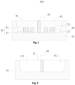
Fig. 1 illustrates a LED package example. -
Fig. 2 illustrates a package housing example inFig. 1 . -
Fig. 3 illustrates a top view of a LED package example. -
Fig. 4 illustrates a light module example. -
Fig. 5 illustrates a top view of the example inFig. 4 . -
Fig. 6 illustrates a panel light device example. -
Fig. 7 illustrates a lighting apparatus embodiment. -
Fig. 8 illustrates a light mixing scheme. -
Fig. 9 illustrates a driver connection example. -
Fig. 10 illustrates a structure of another embodiment. - In
Fig. 7 , a lighting apparatus includes alight source plate 621, multiplelight modules 631 and adriver 622. InFig. 7 , thelight source plate 621 is illustrated with a minimized form for explaining the relation among components, not the actual ratio among components. - Multiple
light modules 631 are placed on thelight source plate 621. In some embodiments, thelight modules 631 are integrated on light strips placed on a plate as shown inFig. 6 . - Each
light module 631 includes aLED package 603 and a lens 606. - The
LED package 603 includes multiple sections, e.g. afirst section 601 and asecond section 602. - At least a LED unit is placed in each section. The LED unit may have one or more LED chips. For example, the LED unit in the
first section 601 has a firsttype LED chip 608 and a secondtype LED chip 609. The LED unit in thesecond section 602 has a firsttype LED chip 611 and a secondLED type chip 610. The first type LED chip may have a different color temperature as the second type LED chip. But, the first type LED chip in thefirst section 601 may have a smaller size than the second type LED chip in thesecond section 602. - By changing a relative ratio of driving currents supplied to the first section and the second section, a different color temperature is obtained.
- Each
section corresponding LED electrodes driver 622. For example, thedriver 622 may supply different driving currents volumes to the twosections - The driver is electrically connected to the LED electrodes for supplying an adjustable ratio of separate driving currents to the LED electrodes to generate a required light parameter by mixing multiple lights emitted by the LED units disposed in the sections of the
light modules 631. - The lens has multiple lens areas for guiding lights of different sections in each light module to generate a mixed light via the lens.
-
Fig. 8 shows an example of mixing lights by a lens. InFig. 8 , twoLED units lights lens 705 further guides direction of the light 703, 704 tolights lights - In some embodiments, the LED package has a first section and a second section.
- In
Fig. 7 , a first LED unit is placed in the first section covered with afirst fluorescent layer 651. A second LED unit is place in thesecond section 602 covered with asecond fluorescent layer 652. - The
first fluorescent layer 651 and thesecond fluorescent layer 652 have different compositions. For example, different chemical fluorescent material are filled in thefirst section 601 and thesecond section 602 to get required output light parameters. - In some embodiments, the
LED package 603 has apackage housing 6031 and aspacer wall 6032. - The
spacer wall 6032 separates thefirst section 601 and thesecond section 602. - In some embodiments, the packaging housing has
tilt bases 635 for respectively placing the first LED unit and the second LED unit so that lights of the first LED unit and the second LED unit overlaps more than 50 percent in the lens. In other words, most of lights are overlapped in the lens 606. - In some embodiments, the first LED unit has at least one first type LED chip and one second type LED chip.
- The second LED unit has at least one first type LED chip and one second type LED chip.
- The driver adjusts the adjustable ratio of separate driving currents to generate the required light parameter.
- In some embodiments, the LED package has a circular external shape, as shown in
Fig. 4 andFig. 5 . - In some embodiments, the first section is semi-circular shape and the second section is semi-circular shape, as shown in
Fig. 5 . - In some embodiments, the light module has an aligning
structure 605 for aligning the lens with the LED package. For example, the LED package has a structure protruding pin and the lens has a socket corresponding to the protruding pin to align the lens and the LED package so as to diffuse light as planned. - In some embodiments, the lens has a convex
external curve surface 607, e.g. the top exterior surface of the lens 606. - In some embodiments, the lens has a concave curve
inner dome 608 facing to the LED package. - In some embodiments, the lens has multiple
micro lenses 661 for guiding lights of different sections to generate the mixed light via the lens. Specifically, the lens may have a different way of design, by placing multiple micro lenses to guide lights in various directions. - In some embodiments, the lens has a package connector for aligning and coupling the LED package, like the aligning
structure 605, but may have an attaching structure to combine the two components. - In some embodiments, the light source plate has multiple grooves for placing multiple light strips, the multiple light modules are placed on the light strips, as shown in
Fig. 6 . There is alight source plate 201 with grooves as an array for placinglight strips 202 mounted withlight modules 100. - In
Fig. 10 , the lighting apparatus may also include alight passing cover 781 connected to thelight source plate 782 forming a container for enclosing the multiple light modules. - In some embodiments, the light passing cover has
multiple cover lenses 784 corresponding to the multiple light strips 783. - In some embodiments, the light strips are detachable to be replaced from the light source plate. For example, the light strip may have a plug structure like a traditional light tube.
- In some embodiments, the lens has a plugging structure for plugging on the light strip.
- In some embodiments, the LED package is electrically connected to the driver when the lens is plugged on the light strip.
- In some embodiments, the sections of the light modules are divided into a first group and a second group.
- The LED electrodes of the sections of the first group and the LED electrodes of the sections of the second group are separately electrically connected to the driver.
- In
Fig. 9 , the LED units in the first group are integrated to thefirst connector 804. The LED units in the second group are integrated to thesecond connector 805. - In some embodiments, the first group is connected to a first connector and the second group is connected to a second connector.
- The driver determines types of the first connector and the second connector to supply corresponding driving currents to the first group and the second group separately. The
driver 801 is connected to thefirst connector 804 with afirst terminal 802. Thedrive 801 is connected to thesecond connector 805 with thesecond terminal 803. - The
driver 801 checks the type of thefirst connector 804 and thesecond connector 805 so as to determine a corresponding driving scheme to generate corresponding driving currents to the fist group and the second group of LED units to mix a required light parameter. - The foregoing description, for purpose of explanation, has been described with reference to specific embodiments.
- Please refer to
Fig. 1 . InFig. 1 , aLED package 10 has aspace wall 30 to divide the LED package into afirst section 41 and asecond section 42. A first fluorescent layer and a second fluorescent layer are filled in the concave containers of thefirst section 41 and thesecond section 42. There are LEDunits 20 placed in thefirst section 41 and thesecond section 42. The LED units in the two sections respectively have two LEDchips 21. -
Fig. 2 show a different view of the example inFig. 1 . The same reference numerals in following drawings refer to the same components and may not be repeated for brevity. - In
Fig. 2 , the first section has aconcave area 111 and the second section has aconcave area 112 to be filled with fluorescent layers. -
Fig. 3 shows a top view of the example inFig. 1 and Fig. 2 . - The two sections respectively have a
positive electrode 901 and anegative electrode 902 so as to receive driving currents separately to change a relative ratio for getting a required mixed light parameter. -
Fig. 4 shows alens 50 with adorm area 53 for placing theLED package 10. The lens has aconcave curve surface 52 for diffusing and mixing lights of different sections of theLED package 10. The lens has a topexterior curve surface 51 for further diffusing the mixed lights. -
Fig. 5 shows a top view of thelens 50. -
Fig. 6 shows a light source plate withmultiple grooves 961 for placing multiple light strips 202. Each light strip haslight modules 100. - The embodiments were chosen and described in order to best explain the principles of the techniques and their practical applications. Others skilled in the art are thereby enabled to best utilize the techniques and various embodiments with various modifications as are suited to the particular use contemplated.
- Although the disclosure and examples have been fully described with reference to the accompanying drawings, it is to be noted that various changes and modifications will become apparent to those skilled in the art.
Claims (13)
- A lighting apparatus, comprising:a light source plate (621);multiple light modules (100,631) placed on the light source plate (621), wherein each light module (631) comprises a LED package (603) and a lens (606), wherein the LED package (603) comprises multiple sections, wherein at least a LED unit is placed in each section, wherein each section has a pair of corresponding LED electrodes (623, 624); anda driver (622) electrically connected to the LED electrodes (623, 624) for supplying an adjustable ratio of separate driving currents to the LED electrodes (623, 624) to generate a required light parameter by mixing multiple lights emitted by the LED units disposed in the sections of the light modules (631),wherein the lens has multiple lens areas for guiding lights of different sections in each light module (631) to generate a mixed light via the lens (606),wherein the light source plate has multiple grooves for placing multiple light strips (202), and the multiple light modules are placed on the light strips (202),furthermore comprising a light passing cover (781) connected to the light source plate forming a container for enclosing the multiple light modules,wherein the light passing cover (781) has multiple cover lenses (784) corresponding to the multiple light strips.
- The lighting apparatus of claim 1, wherein the LED package (603) has a first section (601) and a second section (602), wherein a first LED unit is placed in the first section (601) covered with a first fluorescent layer (651), a second LED unit is place in the second section (602) covered with a second fluorescent layer (652), wherein the first fluorescent layer (651) and the second fluorescent layer (652) have different compositions.
- The lighting apparatus of claim 2, wherein the LED package (603) has a package housing (6031) and a spacer wall (6032), wherein the spacer wall (6032) separates the first section (601) and the second section (602),
preferably, the packaging housing (603) has tilt bases (635) for respectively placing the first LED unit and the second LED unit so that lights of the first LED unit and the second LED unit overlaps more than 50 percent in the lens (606). - The lighting apparatus of claim 2 or 3, wherein the first LED unit has at least one first type LED chip and one second type LED chip, wherein the second LED unit has at least one first type LED chip and one second type LED chip, wherein the driver (622) adjusts the adjustable ratio of separate driving currents to generate the required light parameter.
- The lighting apparatus of any one of claims 2 to 4, wherein the LED package (603) has a circular external shape,
preferably, the first section (601) is semi-circular shape and the second section (602) is semi-circular shape. - The lighting apparatus of any one of claims 2 to 5, wherein the light module (631) has an aligning structure (605) for aligning the lens (606) with the LED package (603).
- The lighting apparatus of any one of claims 2 to 6, wherein the lens (606) has a convex external curve surface,
preferably, the lens (606) has a concave curve inner dome facing to the LED package (603). - The lighting apparatus of any one of claims 2 to 7, wherein the lens (606) has multiple micro lenses for guiding lights of different sections to generate the mixed light via the lens.
- The lighting apparatus of any one of claims 1 to 8, wherein the lens (606) has a package connector for aligning and coupling the LED package (603).
- The lighting apparatus of claim 1, wherein the light strips (202) are detachable to be replaced from the light source plate.
- The lighting apparatus of any one of claims 1 to 10, wherein the lens has a plugging structure for plugging on the light strip,
preferably, the LED package (603) is electrically connected to the driver (622) when the lens is plugged on the light strip. - The lighting apparatus of any one of claims 1 to 11, wherein the sections of the light modules are divided into a first group and a second group, wherein the LED electrodes of the sections of the first group and the LED electrodes of the sections of the second group are separately electrically connected to the driver (801).
- The lighting apparatus of claim 12, wherein the first group is connected to a first connector (804) and the second group is connected to a second connector (805), the driver (622) determines types of the first connector (804) and the second connector (805) to supply corresponding driving currents to the first group and the second group separately.
Applications Claiming Priority (1)
| Application Number | Priority Date | Filing Date | Title |
|---|---|---|---|
| CN202021576106.3U CN212961082U (en) | 2020-07-31 | 2020-07-31 | A light-emitting device and a direct type panel light |
Publications (3)
| Publication Number | Publication Date |
|---|---|
| EP3945575A2 EP3945575A2 (en) | 2022-02-02 |
| EP3945575A3 EP3945575A3 (en) | 2022-03-02 |
| EP3945575B1 true EP3945575B1 (en) | 2024-12-18 |
Family
ID=75345546
Family Applications (1)
| Application Number | Title | Priority Date | Filing Date |
|---|---|---|---|
| EP21188162.8A Active EP3945575B1 (en) | 2020-07-31 | 2021-07-28 | Lighting apparatus |
Country Status (3)
| Country | Link |
|---|---|
| US (1) | US20220034478A1 (en) |
| EP (1) | EP3945575B1 (en) |
| CN (1) | CN212961082U (en) |
Family Cites Families (6)
| Publication number | Priority date | Publication date | Assignee | Title |
|---|---|---|---|---|
| US9793247B2 (en) * | 2005-01-10 | 2017-10-17 | Cree, Inc. | Solid state lighting component |
| US9345095B2 (en) * | 2010-04-08 | 2016-05-17 | Ledengin, Inc. | Tunable multi-LED emitter module |
| US9515055B2 (en) * | 2012-05-14 | 2016-12-06 | Cree, Inc. | Light emitting devices including multiple anodes and cathodes |
| DE102016122237A1 (en) * | 2016-11-18 | 2018-05-24 | Osram Opto Semiconductors Gmbh | Multipixel LED device and method of operating a multi-pixel LED device |
| US11101248B2 (en) * | 2017-08-18 | 2021-08-24 | Creeled, Inc. | Light emitting diodes, components and related methods |
| US20200236744A1 (en) * | 2019-01-17 | 2020-07-23 | Xiamen Eco Lighting Co. Ltd. | Led light apparatus with adjustable characteristic |
-
2020
- 2020-07-31 CN CN202021576106.3U patent/CN212961082U/en active Active
-
2021
- 2021-07-23 US US17/384,040 patent/US20220034478A1/en not_active Abandoned
- 2021-07-28 EP EP21188162.8A patent/EP3945575B1/en active Active
Also Published As
| Publication number | Publication date |
|---|---|
| EP3945575A3 (en) | 2022-03-02 |
| EP3945575A2 (en) | 2022-02-02 |
| US20220034478A1 (en) | 2022-02-03 |
| CN212961082U (en) | 2021-04-13 |
Similar Documents
| Publication | Publication Date | Title |
|---|---|---|
| US11313538B2 (en) | Lighting apparatus | |
| US11118739B2 (en) | LED filament light bulb apparatus | |
| US11930567B2 (en) | Lighting apparatus | |
| US11231147B2 (en) | Light bulb apparatus having a twisted LED filament for improved luminous efficiency and light distribution | |
| US12169048B2 (en) | Linear light apparatus | |
| US11598511B2 (en) | Lighting apparatus | |
| US11598514B2 (en) | Downlight apparatus | |
| US11598501B2 (en) | Downlight apparatus | |
| EP3943803B1 (en) | Lighting apparatus | |
| US11761615B2 (en) | Lighting apparatus | |
| US12078299B2 (en) | Light apparatus | |
| US20210262620A1 (en) | Lighting apparatus | |
| US20210116087A1 (en) | Lighting apparatus | |
| US11852304B1 (en) | Lighting apparatus | |
| US11543089B2 (en) | Lighting apparatus | |
| US11828423B2 (en) | Light bulb apparatus | |
| EP3945575A2 (en) | Lighting apparatus | |
| US11255493B2 (en) | Light bulb apparatus | |
| US20240027035A1 (en) | Lighting apparatus | |
| US20210116086A1 (en) | Lighting apparatus | |
| US11898729B2 (en) | Lighting apparatus | |
| EP4040044A1 (en) | Lighting apparatus | |
| US11408600B2 (en) | Lighting apparatus | |
| US12072092B2 (en) | Lighting apparatus | |
| EP3954941B1 (en) | Panel light apparatus |
Legal Events
| Date | Code | Title | Description |
|---|---|---|---|
| PUAI | Public reference made under article 153(3) epc to a published international application that has entered the european phase |
Free format text: ORIGINAL CODE: 0009012 |
|
| STAA | Information on the status of an ep patent application or granted ep patent |
Free format text: STATUS: REQUEST FOR EXAMINATION WAS MADE |
|
| PUAL | Search report despatched |
Free format text: ORIGINAL CODE: 0009013 |
|
| 17P | Request for examination filed |
Effective date: 20210728 |
|
| AK | Designated contracting states |
Kind code of ref document: A2 Designated state(s): AL AT BE BG CH CY CZ DE DK EE ES FI FR GB GR HR HU IE IS IT LI LT LU LV MC MK MT NL NO PL PT RO RS SE SI SK SM TR |
|
| STAA | Information on the status of an ep patent application or granted ep patent |
Free format text: STATUS: EXAMINATION IS IN PROGRESS |
|
| AK | Designated contracting states |
Kind code of ref document: A3 Designated state(s): AL AT BE BG CH CY CZ DE DK EE ES FI FR GB GR HR HU IE IS IT LI LT LU LV MC MK MT NL NO PL PT RO RS SE SI SK SM TR |
|
| RIC1 | Information provided on ipc code assigned before grant |
Ipc: H01L 33/50 20100101ALI20220121BHEP Ipc: H01L 33/48 20100101ALI20220121BHEP Ipc: H01L 25/075 20060101AFI20220121BHEP |
|
| 17Q | First examination report despatched |
Effective date: 20220208 |
|
| GRAP | Despatch of communication of intention to grant a patent |
Free format text: ORIGINAL CODE: EPIDOSNIGR1 |
|
| STAA | Information on the status of an ep patent application or granted ep patent |
Free format text: STATUS: GRANT OF PATENT IS INTENDED |
|
| INTG | Intention to grant announced |
Effective date: 20240724 |
|
| GRAS | Grant fee paid |
Free format text: ORIGINAL CODE: EPIDOSNIGR3 |
|
| GRAA | (expected) grant |
Free format text: ORIGINAL CODE: 0009210 |
|
| STAA | Information on the status of an ep patent application or granted ep patent |
Free format text: STATUS: THE PATENT HAS BEEN GRANTED |
|
| AK | Designated contracting states |
Kind code of ref document: B1 Designated state(s): AL AT BE BG CH CY CZ DE DK EE ES FI FR GB GR HR HU IE IS IT LI LT LU LV MC MK MT NL NO PL PT RO RS SE SI SK SM TR |
|
| REG | Reference to a national code |
Ref country code: CH Ref legal event code: EP |
|
| REG | Reference to a national code |
Ref country code: DE Ref legal event code: R096 Ref document number: 602021023469 Country of ref document: DE |
|
| REG | Reference to a national code |
Ref country code: IE Ref legal event code: FG4D |
|
| REG | Reference to a national code |
Ref country code: LT Ref legal event code: MG9D |
|
| PG25 | Lapsed in a contracting state [announced via postgrant information from national office to epo] |
Ref country code: HR Free format text: LAPSE BECAUSE OF FAILURE TO SUBMIT A TRANSLATION OF THE DESCRIPTION OR TO PAY THE FEE WITHIN THE PRESCRIBED TIME-LIMIT Effective date: 20241218 |
|
| PG25 | Lapsed in a contracting state [announced via postgrant information from national office to epo] |
Ref country code: FI Free format text: LAPSE BECAUSE OF FAILURE TO SUBMIT A TRANSLATION OF THE DESCRIPTION OR TO PAY THE FEE WITHIN THE PRESCRIBED TIME-LIMIT Effective date: 20241218 |
|
| PG25 | Lapsed in a contracting state [announced via postgrant information from national office to epo] |
Ref country code: BG Free format text: LAPSE BECAUSE OF FAILURE TO SUBMIT A TRANSLATION OF THE DESCRIPTION OR TO PAY THE FEE WITHIN THE PRESCRIBED TIME-LIMIT Effective date: 20241218 |
|
| PG25 | Lapsed in a contracting state [announced via postgrant information from national office to epo] |
Ref country code: NO Free format text: LAPSE BECAUSE OF FAILURE TO SUBMIT A TRANSLATION OF THE DESCRIPTION OR TO PAY THE FEE WITHIN THE PRESCRIBED TIME-LIMIT Effective date: 20250318 |
|
| REG | Reference to a national code |
Ref country code: NL Ref legal event code: MP Effective date: 20241218 |
|
| PG25 | Lapsed in a contracting state [announced via postgrant information from national office to epo] |
Ref country code: LV Free format text: LAPSE BECAUSE OF FAILURE TO SUBMIT A TRANSLATION OF THE DESCRIPTION OR TO PAY THE FEE WITHIN THE PRESCRIBED TIME-LIMIT Effective date: 20241218 Ref country code: GR Free format text: LAPSE BECAUSE OF FAILURE TO SUBMIT A TRANSLATION OF THE DESCRIPTION OR TO PAY THE FEE WITHIN THE PRESCRIBED TIME-LIMIT Effective date: 20250319 |
|
| PG25 | Lapsed in a contracting state [announced via postgrant information from national office to epo] |
Ref country code: RS Free format text: LAPSE BECAUSE OF FAILURE TO SUBMIT A TRANSLATION OF THE DESCRIPTION OR TO PAY THE FEE WITHIN THE PRESCRIBED TIME-LIMIT Effective date: 20250318 |
|
| PG25 | Lapsed in a contracting state [announced via postgrant information from national office to epo] |
Ref country code: NL Free format text: LAPSE BECAUSE OF FAILURE TO SUBMIT A TRANSLATION OF THE DESCRIPTION OR TO PAY THE FEE WITHIN THE PRESCRIBED TIME-LIMIT Effective date: 20241218 |
|
| REG | Reference to a national code |
Ref country code: AT Ref legal event code: MK05 Ref document number: 1752966 Country of ref document: AT Kind code of ref document: T Effective date: 20241218 |
|
| PG25 | Lapsed in a contracting state [announced via postgrant information from national office to epo] |
Ref country code: SM Free format text: LAPSE BECAUSE OF FAILURE TO SUBMIT A TRANSLATION OF THE DESCRIPTION OR TO PAY THE FEE WITHIN THE PRESCRIBED TIME-LIMIT Effective date: 20241218 |
|
| PG25 | Lapsed in a contracting state [announced via postgrant information from national office to epo] |
Ref country code: PL Free format text: LAPSE BECAUSE OF FAILURE TO SUBMIT A TRANSLATION OF THE DESCRIPTION OR TO PAY THE FEE WITHIN THE PRESCRIBED TIME-LIMIT Effective date: 20241218 |
|
| PG25 | Lapsed in a contracting state [announced via postgrant information from national office to epo] |
Ref country code: ES Free format text: LAPSE BECAUSE OF FAILURE TO SUBMIT A TRANSLATION OF THE DESCRIPTION OR TO PAY THE FEE WITHIN THE PRESCRIBED TIME-LIMIT Effective date: 20241218 |
|
| PG25 | Lapsed in a contracting state [announced via postgrant information from national office to epo] |
Ref country code: IS Free format text: LAPSE BECAUSE OF FAILURE TO SUBMIT A TRANSLATION OF THE DESCRIPTION OR TO PAY THE FEE WITHIN THE PRESCRIBED TIME-LIMIT Effective date: 20250418 |
|
| PG25 | Lapsed in a contracting state [announced via postgrant information from national office to epo] |
Ref country code: PT Free format text: LAPSE BECAUSE OF FAILURE TO SUBMIT A TRANSLATION OF THE DESCRIPTION OR TO PAY THE FEE WITHIN THE PRESCRIBED TIME-LIMIT Effective date: 20250421 |
|
| PG25 | Lapsed in a contracting state [announced via postgrant information from national office to epo] |
Ref country code: EE Free format text: LAPSE BECAUSE OF FAILURE TO SUBMIT A TRANSLATION OF THE DESCRIPTION OR TO PAY THE FEE WITHIN THE PRESCRIBED TIME-LIMIT Effective date: 20241218 |
|
| PG25 | Lapsed in a contracting state [announced via postgrant information from national office to epo] |
Ref country code: RO Free format text: LAPSE BECAUSE OF FAILURE TO SUBMIT A TRANSLATION OF THE DESCRIPTION OR TO PAY THE FEE WITHIN THE PRESCRIBED TIME-LIMIT Effective date: 20241218 Ref country code: AT Free format text: LAPSE BECAUSE OF FAILURE TO SUBMIT A TRANSLATION OF THE DESCRIPTION OR TO PAY THE FEE WITHIN THE PRESCRIBED TIME-LIMIT Effective date: 20241218 |
|
| PG25 | Lapsed in a contracting state [announced via postgrant information from national office to epo] |
Ref country code: SK Free format text: LAPSE BECAUSE OF FAILURE TO SUBMIT A TRANSLATION OF THE DESCRIPTION OR TO PAY THE FEE WITHIN THE PRESCRIBED TIME-LIMIT Effective date: 20241218 |
|
| PG25 | Lapsed in a contracting state [announced via postgrant information from national office to epo] |
Ref country code: CZ Free format text: LAPSE BECAUSE OF FAILURE TO SUBMIT A TRANSLATION OF THE DESCRIPTION OR TO PAY THE FEE WITHIN THE PRESCRIBED TIME-LIMIT Effective date: 20241218 |
|
| PG25 | Lapsed in a contracting state [announced via postgrant information from national office to epo] |
Ref country code: SE Free format text: LAPSE BECAUSE OF FAILURE TO SUBMIT A TRANSLATION OF THE DESCRIPTION OR TO PAY THE FEE WITHIN THE PRESCRIBED TIME-LIMIT Effective date: 20241218 |
|
| REG | Reference to a national code |
Ref country code: DE Ref legal event code: R097 Ref document number: 602021023469 Country of ref document: DE |
|
| PG25 | Lapsed in a contracting state [announced via postgrant information from national office to epo] |
Ref country code: DK Free format text: LAPSE BECAUSE OF FAILURE TO SUBMIT A TRANSLATION OF THE DESCRIPTION OR TO PAY THE FEE WITHIN THE PRESCRIBED TIME-LIMIT Effective date: 20241218 |
|
| PGFP | Annual fee paid to national office [announced via postgrant information from national office to epo] |
Ref country code: DE Payment date: 20250627 Year of fee payment: 5 |
|
| PGFP | Annual fee paid to national office [announced via postgrant information from national office to epo] |
Ref country code: IT Payment date: 20250627 Year of fee payment: 5 |
|
| PLBE | No opposition filed within time limit |
Free format text: ORIGINAL CODE: 0009261 |
|
| STAA | Information on the status of an ep patent application or granted ep patent |
Free format text: STATUS: NO OPPOSITION FILED WITHIN TIME LIMIT |
|
| REG | Reference to a national code |
Ref country code: CH Ref legal event code: L10 Free format text: ST27 STATUS EVENT CODE: U-0-0-L10-L00 (AS PROVIDED BY THE NATIONAL OFFICE) Effective date: 20251029 |
|
| 26N | No opposition filed |
Effective date: 20250919 |
|
| REG | Reference to a national code |
Ref country code: DE Ref legal event code: R079 Ref document number: 602021023469 Country of ref document: DE Free format text: PREVIOUS MAIN CLASS: H01L0025075000 Ipc: H10H0029240000 |
|
| REG | Reference to a national code |
Ref country code: CH Ref legal event code: H13 Free format text: ST27 STATUS EVENT CODE: U-0-0-H10-H13 (AS PROVIDED BY THE NATIONAL OFFICE) Effective date: 20260224 |
|
| PG25 | Lapsed in a contracting state [announced via postgrant information from national office to epo] |
Ref country code: LU Free format text: LAPSE BECAUSE OF NON-PAYMENT OF DUE FEES Effective date: 20250728 |
|
| GBPC | Gb: european patent ceased through non-payment of renewal fee |
Effective date: 20250728 |
|
| REG | Reference to a national code |
Ref country code: BE Ref legal event code: MM Effective date: 20250731 |
|
| PG25 | Lapsed in a contracting state [announced via postgrant information from national office to epo] |
Ref country code: GB Free format text: LAPSE BECAUSE OF NON-PAYMENT OF DUE FEES Effective date: 20250728 |
|
| PG25 | Lapsed in a contracting state [announced via postgrant information from national office to epo] |
Ref country code: BE Free format text: LAPSE BECAUSE OF NON-PAYMENT OF DUE FEES Effective date: 20250731 |
|
| PG25 | Lapsed in a contracting state [announced via postgrant information from national office to epo] |
Ref country code: FR Free format text: LAPSE BECAUSE OF NON-PAYMENT OF DUE FEES Effective date: 20250731 |
|
| PG25 | Lapsed in a contracting state [announced via postgrant information from national office to epo] |
Ref country code: CH Free format text: LAPSE BECAUSE OF NON-PAYMENT OF DUE FEES Effective date: 20250731 |