EP3945536A1 - A hybrid switching apparatus of the withdrawable type - Google Patents
A hybrid switching apparatus of the withdrawable type Download PDFInfo
- Publication number
- EP3945536A1 EP3945536A1 EP20188245.3A EP20188245A EP3945536A1 EP 3945536 A1 EP3945536 A1 EP 3945536A1 EP 20188245 A EP20188245 A EP 20188245A EP 3945536 A1 EP3945536 A1 EP 3945536A1
- Authority
- EP
- European Patent Office
- Prior art keywords
- switching
- switching unit
- condition
- state
- controller
- Prior art date
- Legal status (The legal status is an assumption and is not a legal conclusion. Google has not performed a legal analysis and makes no representation as to the accuracy of the status listed.)
- Granted
Links
Images



Classifications
-
- H—ELECTRICITY
- H01—ELECTRIC ELEMENTS
- H01H—ELECTRIC SWITCHES; RELAYS; SELECTORS; EMERGENCY PROTECTIVE DEVICES
- H01H9/00—Details of switching devices, not covered by groups H01H1/00 - H01H7/00
- H01H9/54—Circuit arrangements not adapted to a particular application of the switching device and for which no provision exists elsewhere
- H01H9/548—Electromechanical and static switch connected in series
-
- H—ELECTRICITY
- H02—GENERATION; CONVERSION OR DISTRIBUTION OF ELECTRIC POWER
- H02H—EMERGENCY PROTECTIVE CIRCUIT ARRANGEMENTS
- H02H7/00—Emergency protective circuit arrangements specially adapted for specific types of electric machines or apparatus or for sectionalised protection of cable or line systems, and effecting automatic switching in the event of an undesired change from normal working conditions
- H02H7/26—Sectionalised protection of cable or line systems, e.g. for disconnecting a section on which a short-circuit, earth fault, or arc discharge has occured
-
- H—ELECTRICITY
- H01—ELECTRIC ELEMENTS
- H01H—ELECTRIC SWITCHES; RELAYS; SELECTORS; EMERGENCY PROTECTIVE DEVICES
- H01H9/00—Details of switching devices, not covered by groups H01H1/00 - H01H7/00
- H01H9/54—Circuit arrangements not adapted to a particular application of the switching device and for which no provision exists elsewhere
- H01H9/541—Contacts shunted by semiconductor devices
- H01H9/542—Contacts shunted by static switch means
-
- H—ELECTRICITY
- H02—GENERATION; CONVERSION OR DISTRIBUTION OF ELECTRIC POWER
- H02J—ELECTRIC POWER NETWORKS; CIRCUIT ARRANGEMENTS OR SYSTEMS FOR SUPPLYING OR DISTRIBUTING ELECTRIC POWER; SYSTEMS FOR STORING ELECTRIC ENERGY
- H02J13/00—Circuit arrangements for providing remote monitoring or remote control of equipment in a power distribution network
- H02J13/18—Circuit arrangements for providing remote monitoring or remote control of equipment in a power distribution network characterised by the remotely-controlled equipment, e.g. converters or transformers
- H02J13/34—Circuit arrangements for providing remote monitoring or remote control of equipment in a power distribution network characterised by the remotely-controlled equipment, e.g. converters or transformers the equipment being switches, relays or circuit breakers
-
- H—ELECTRICITY
- H01—ELECTRIC ELEMENTS
- H01H—ELECTRIC SWITCHES; RELAYS; SELECTORS; EMERGENCY PROTECTIVE DEVICES
- H01H9/00—Details of switching devices, not covered by groups H01H1/00 - H01H7/00
- H01H9/54—Circuit arrangements not adapted to a particular application of the switching device and for which no provision exists elsewhere
- H01H9/541—Contacts shunted by semiconductor devices
- H01H9/542—Contacts shunted by static switch means
- H01H2009/544—Contacts shunted by static switch means the static switching means being an insulated gate bipolar transistor, e.g. IGBT, Darlington configuration of FET and bipolar transistor
-
- H—ELECTRICITY
- H01—ELECTRIC ELEMENTS
- H01H—ELECTRIC SWITCHES; RELAYS; SELECTORS; EMERGENCY PROTECTIVE DEVICES
- H01H71/00—Details of the protective switches or relays covered by groups H01H73/00 - H01H83/00
- H01H71/10—Operating or release mechanisms
- H01H71/12—Automatic release mechanisms with or without manual release
- H01H71/123—Automatic release mechanisms with or without manual release using a solid-state trip unit
- H01H2071/124—Automatic release mechanisms with or without manual release using a solid-state trip unit with a hybrid structure, the solid state trip device being combined with a thermal or a electromagnetic trip
-
- H—ELECTRICITY
- H01—ELECTRIC ELEMENTS
- H01H—ELECTRIC SWITCHES; RELAYS; SELECTORS; EMERGENCY PROTECTIVE DEVICES
- H01H33/00—High-tension or heavy-current switches with arc-extinguishing or arc-preventing means
- H01H33/02—Details
- H01H33/46—Interlocking mechanisms
-
- H—ELECTRICITY
- H01—ELECTRIC ELEMENTS
- H01H—ELECTRIC SWITCHES; RELAYS; SELECTORS; EMERGENCY PROTECTIVE DEVICES
- H01H71/00—Details of the protective switches or relays covered by groups H01H73/00 - H01H83/00
- H01H71/10—Operating or release mechanisms
- H01H71/12—Automatic release mechanisms with or without manual release
- H01H71/123—Automatic release mechanisms with or without manual release using a solid-state trip unit
-
- H—ELECTRICITY
- H02—GENERATION; CONVERSION OR DISTRIBUTION OF ELECTRIC POWER
- H02B—BOARDS, SUBSTATIONS OR SWITCHING ARRANGEMENTS FOR THE SUPPLY OR DISTRIBUTION OF ELECTRIC POWER
- H02B11/00—Switchgear having carriage withdrawable for isolation
- H02B11/12—Switchgear having carriage withdrawable for isolation with isolation by horizontal withdrawal
Definitions
- low voltage switching apparatuses are used in electric circuits or grids to allow the correct operation of specific circuit or grid sections.
- these apparatuses may be used to ensure the availability of a nominal current necessary for several utilities, enable the proper insertion and disconnection of electric loads and protect (especially circuit breakers) the electric grid and installed electric loads against fault events, such as overloads and short circuits.
- the controller of the switching apparatus comprises an interface section including one or more input ports adapted to receive input commands indicative of a desired operating state for said switching apparatus.
- Each second electric pole 2A comprises electric contacts 20 that can operate in a coupled state or on an uncoupled state to allow or interrupt a current flow.
- the electrical contacts 20 of each electric pole 2A comprise a fixed electric contact and a movable electric contact (not shown). Each movable contact can be actuated to couple with or uncouple from the fixed contact.
- the trip actuators 25 are operatively coupleable with a suitable actuation mechanism (not shown) adapted to actuate the movable contacts of the second switching unit.
- a suitable actuation mechanism (not shown) adapted to actuate the movable contacts of the second switching unit.
- Such an actuation mechanism (which may be of known type) is conveniently designed to move the movable contacts of the second switching unit 2 upon tripping by the above-mentioned trip actuators.
- the second switching unit 2 may carry out an opening manoeuvre or a closing manoeuvre upon receiving trip signals T2 from a controller.
- the switching apparatus 100 comprises a first carriage (not shown), on which the first switching unit 1 is mounted.
- a first carriage is slidingly coupled to a supporting frame of the switching apparatus 100.
- both the first switching unit 1 and the first carriage are movable with respect to the fixed section of the switching apparatus.
- the switching apparatus 100 comprises a first actuating arrangement 7 (which may be of known type) adapted to actuate the first switching unit 1, upon activation by a user (e.g. through a suitable command button), in order to carry out at least a withdrawal manoeuvre of said switching unit.
- controller 3 and the human-machine interface 5 may be arranged at industrial level according to hardware solutions of known type. Thus, hereinafter, they will be not described in further structural or circuit details, for the sake of brevity.
- the external auxiliary power supply V AUX is derived from the electric line 50 through a suitable auxiliary power interface device (not shown) or it can be provided by any external power source.
- the switching units 1, 2 When the switching units 1, 2 operate according to the third operating configuration [O], line currents and possible leakage currents are not allowed to flow along the electric poles 1A, 2A of the switching units 1, 2 as the both the switching units 1 are in an open condition OFF.
- the first and second line conductors 51, 52 of the electric line 50 are disconnected and there is a galvanic insulation between said line conductors.
- the third operating configuration [O] of the switching units 1, 2 therefore corresponds to an open state of the switching apparatus 100.
- the switching apparatus 100 When it is in a stand-by state (second operating configuration [X] of the switching units 1, 2), the switching apparatus 100 automatically to an open state (third operating configuration [O] of the switching units 1, 2) in response to a fault condition of the power supply stage 4.
- the controller 3 commands said switching units 1, 2 to remain in the third operating configuration [O] in response to receiving sensing signals S2 indicative of a fault condition of the power supply stage 4 ( figure 6 ).
- the switching apparatus 100 cannot switch in a different state (e.g. a stand-by state or a closed state) due to a fault condition of the power supply stage 4.
Landscapes
- Engineering & Computer Science (AREA)
- Power Engineering (AREA)
- Keying Circuit Devices (AREA)
- Driving Mechanisms And Operating Circuits Of Arc-Extinguishing High-Tension Switches (AREA)
- Remote Monitoring And Control Of Power-Distribution Networks (AREA)
Abstract
- a withdrawable first switching unit having one or more first electric poles;
- a withdrawable second switching unit having one or more second electric poles and electrically connected ins series with said first switching unit;
- a controller implementing control strategies directed to increase the safety of the withdrawal manoeuvres of said first and second switching units.
Description
- The present invention relates to a switching apparatus for electric power distribution grids, such as a circuit breaker or another apparatus of similar type.
- As it is known, low voltage switching apparatuses are used in electric circuits or grids to allow the correct operation of specific circuit or grid sections. For instance, these apparatuses may be used to ensure the availability of a nominal current necessary for several utilities, enable the proper insertion and disconnection of electric loads and protect (especially circuit breakers) the electric grid and installed electric loads against fault events, such as overloads and short circuits.
- Most traditional switching apparatuses include an electro-mechanical switching unit having one or more electric poles, each comprising a pair of electric contacts adapted to be coupled or uncoupled to allow or interrupt line currents along the electric poles.
- Although they have proven to be very robust and reliable, second switching apparatuses show a relatively long interruption time in DC applications, mainly at relatively high voltages (between 1 - 1,5 kV DC). As a consequence, electric arcs, which usually strike between electric contacts under separation, may last for a relatively long time. This may cause severe wear phenomena of the electric contacts and a consequent remarkable reduction of the operating reliability and electrical endurance.
- In order to overcome these technical issues, they have been designed switching apparatuses (also referred to as "SSCBs" - Solid-State Circuit Breakers) including a switching unit having, for each electric pole, one or more solid-state switches, i.e. semiconductor-based transistors or thyristors adapted to operate in a conduction state or in an interdiction state to allow or interrupt a current flow.
- The main advantage of SSCBs consists in that they have a potentially unlimited electrical endurance due to the circumstance that breaking operations are carried out without the formation of electric arcs. Further, their interruption time is remarkably shorter in comparison with the interruption time of switching apparatuses of the electro-mechanical type.
- An important drawback of SSCBs consists in that they cannot generally provide galvanic insulation between the line conductors connected thereto. In fact, when a voltage is applied to the power terminals of solid-state switches (e.g. the collector and emitter terminals of an IGBT), leakage currents typically flow even if said switches are in an interdiction state. Recently, they have been developed switching apparatuses including a SSCB switching unit and an electro-mechanical switching unit electrically connected in series.
- These switching apparatuses (generally referred to as "hybrid switching apparatuses") allow exploiting all the advantages provided by SSCBs in terms of reliability and reduction of the interruption time and, at the same time, they allow obtaining galvanic insulation between the line conductors connected thereto.
- As it is known, many hybrid switching apparatuses are of the "withdrawable" type. In this case, both the SSCB and the second switching units are movable with respect to a fixed section of the switching apparatus. In particular, each switching unit is mounted on a carriage in such a way to be reversibly movable between an insertion position and a withdrawn position with respect to the fixed section of the switching apparatus.
- Hybrid switching apparatuses of the withdrawable type have further advantages in terms of efficiency of use and safety. In fact, both the above-mentioned switching units may be brought in a withdrawn position for easily carrying out on-the-field tests or maintenance interventions with the switching units completely disconnected from the line conductors. However, also these switching apparatuses have some aspects to improve, particularly for what concerning the coordinated control of the SSCB switching unit and the electro-mechanical switching unit in operation.
- Currently adopted control strategies do not allow these switching apparatuses to operate in a completely safe way in some circumstances, for example when they cannot receive an external auxiliary power supply to feed their internal low-voltage components, e.g. electronic circuits, actuators or controllers.
- The main aim of the present invention is providing a hybrid switching apparatus of the withdrawable type, which makes it possible to overcome or mitigate the aforementioned technical issues of the state of the art.
- Within this aim, an object of the present invention is providing a switching apparatus, which ensures high levels of safety and efficiency in operation.
- Another object of the present invention is providing a switching apparatus, which can be easily controlled in operation without arranging complex and expensive control resources. Another object of the present invention is providing a switching apparatus relatively easy and cheap to manufacture at industrial level.
- This aim and these objects, together with other objects that will become evident from the following description and accompanying drawings, are achieved, according to the present invention, by a switching apparatus, according to
claim 1 and the related dependent claims set out below. - The switching apparatus, according to the invention, comprises:
- one or more first and second line terminals intended to be electrically connected to corresponding first and second line conductors of an electric line, respectively;
- a first switching unit having one or more first electric poles, each first electric pole comprising a first pole contact) intended to be electrically connected to a corresponding first line terminal, a second pole contact) and one or more solid-state switches electrically connected to said first and second pole contacts and adapted to operate in a conduction state or in an interdiction state to allow or interrupt a current flow.
Said first switching unit is reversibly switchable between a closed condition, in which said solid-state switches are in a conduction state, and an open condition, in which said solid-state switches are in an interdiction state.
Said first switching unit is reversibly movable between an insertion condition, in which said first pole contacts are coupled with said first line terminals, and a withdrawal condition, in which said first pole contacts are uncoupled from said first line terminals; - a second switching unit having one or more second electric poles, each second electric pole comprising a third pole contact intended to be electrically connected to a corresponding second pole contact of the first switching unit, a fourth pole contact intended to be electrically connected to a corresponding second line terminal and electric contacts electrically connected to said third and fourth pole contacts and adapted to operate in a coupled state or on an uncoupled state to allow or interrupt a current flow.
- Said second switching unit is reversibly movable between an insertion condition, in which said fourth pole contacts are coupled with said second line terminals, and a withdrawal condition, in which said fourth pole contacts are uncoupled from said second line terminals. According to the invention, the controller of the switching apparatus is configured to control said first and second switching units, so that both said first and second switching units are in an open condition, when said power supply stage is subject to a fault condition.
- Preferably, said controller is configured to command said first switching unit and said second switching unit to switch to or remain in an open condition, in response to receiving sensing signals indicative of a fault condition of said power supply stage.
- Preferably, the switching apparatus comprises power supply sensing means adapted to provide sensing signals indicative of the operating conditions of said power supply stage (4) to said controller.
- According to an aspect of the invention, the controller of the switching apparatus is configured to control the operating conditions of said first and second switching units, so that said first and second switching units operate in combination according to the following operating configurations:
- a first operating configuration corresponding to a closed state of said switching apparatus, in which both said first and second switching units are in a closed condition; or
- a second operating configuration corresponding to a stand-by state of said switching apparatus, in which said first switching unit is in an open condition and said second switching unit is in a closed condition; or
- a third operating configuration corresponding to an open state of said switching apparatus, in which both said first and second switching units are in an open condition.
- Said controller is configured to control said first and second switching units, so that said first and second switching units are in said third operating configuration, when said power supply stage is subject to a fault condition.
- Preferably, said controller is configured to command said first switching unit and said second switching unit to switch to or remain in said third operating configuration, in response to receiving sensing signals indicative of a fault condition of said power supply stage.
- Preferably, when said first and second switching units operate in combination according to said first operating configuration, said controller commands said first and second switching units to switch to said second operating configuration and subsequently to switch to said third operating configuration in response to receiving sensing signals indicative of a fault condition of said power supply stage.
- Preferably, when said first and second switching units operate in combination according to said second operating configuration, said controller commands said first and second switching units to switch to said third operating configuration in response to receiving sensing signals indicative of a fault condition of said power supply stage.
- Preferably, when said first and second switching units operate in combination according to said third operating configuration, said controller commands said first and second switching units to remain in said third operating configuration in response to receiving sensing signals indicative of a fault condition of said power supply stage.
- According to an aspect of the invention, the switching apparatus comprises a first actuating arrangement adapted to actuate said first switching unit at least during a withdrawal manoeuvre of said first switching unit, upon activation by a user.
- According to an aspect of the invention, the switching apparatus comprises a second actuating arrangement (8) adapted to actuate said second switching unit at least during a withdrawal manoeuvre of said second switching unit, upon activation by a user.
- According to an aspect of the invention, the controller of the switching apparatus comprises an interface section including one or more input ports adapted to receive input commands indicative of a desired operating state for said switching apparatus.
- Preferably, the switching apparatus comprises a human-machine interface in communication with said interface section. Said human-interface is adapted to provide said input commands upon an interaction with a user.
- Preferably, said interface section is capable of receiving said input commands from a remote computerized device.
- According to an aspect of the invention, the controller of the switching apparatus is included in said first switching unit.
- Further characteristics and advantages of the present invention shall emerge more clearly from the description of preferred but not exclusive embodiments illustrated purely by way of examples and without limitation in the attached drawings, in which:
-
figure 1 schematically shows the switching apparatus, according to the invention; -
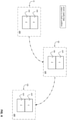
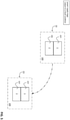
figures 2-6 schematically show the operation of the switching apparatus, according to the invention. - With reference to the mentioned figures, the present invention relates to a switching
apparatus 100 for electric power distribution grids, such as a circuit breaker, a disconnector, a contactor, or the like. - The
switching apparatus 100 is particularly adapted for installation in low voltage electric grids or systems. However, it may be successfully employed also in medium voltage electric grids or systems. - For the purposes of the present invention, the term "low voltage" (LV) relates to operating voltages lower than 1 kV AC and 1.5 kV DC while the term "medium voltage" (MV) relates to higher operating voltages up to some tens of kV, e.g. up to 72 kV AC and 100 kV DC.
- In general, the
switching apparatus 100 is intended to be electrically connected to anelectric line 50. Typically, theelectric line 50 comprises one or morefirst line conductors 51, which may be electrically connected to an equivalent electric power source (e.g. an electric power feeding or generation system or a section of electric grid), and one or moresecond line conductors 52, which may be connected to an equivalent electric load (e.g. an electric system or apparatus or a section of electric grid). - In the embodiment shown in the cited figures, the
electric line 50 is of the three-phase type. However, in principle, it may include a different number of electric phases. - The
switching apparatus 100 comprises one or more first andsecond line terminals second line conductors electric line 50, respectively. - Conveniently, the first and
second line terminals - The
switching apparatus 100 comprises afirst switching unit 1 of the SSCB type and asecond switching unit 2 of the electro-mechanical type, which in operation are electrically connected in series between the above-mentionedline terminals - The
first switching unit 1 comprises one or more firstelectric poles 1A. - The number of electric poles of the first switching unit may vary, according to the needs. In the embodiment shown in the cited figures, the first switching unit is of the three-phase type and it comprises three-electric poles. However, according to other embodiments of the invention (not shown), the first switching unit may include a different number of electric poles.
- Each
electric pole 1A is intended to be electrically connected to a correspondingfirst line conductor 51 of theelectric line 50 and with a corresponding electric pole of thesecond switching unit 2. - Each
electric pole 1A comprises afirst pole contact 11 intended to be electrically connected to a correspondingfirst line terminal 91 of the switching apparatus and asecond pole contact 12 intended to be electrically connected to acorresponding pole contact 23 of thesecond switching unit 2. - Each
electric pole 1A comprises one or more solid-state switches 10 adapted to operate in a conduction state or in an interdiction state to allow or interrupt a current flow. - Solid-state switches ("SSCBs) 10 may include, for example, MOSFETs, Insulated Gate Bipolar Transistors ("IGBTs"), Gate Turn-Off Thyristors (GTOs), Integrated Gate-Commutated Thyristors ("IGCTs"), or the like.
- The solid-
state switches 10 of eachelectric pole 1A are electrically connected between thepole contacts - In operation, the
first switching unit 1 is capable of reversibly switching between a closed condition ON, in which the solid-state switches 10 of theelectric poles 1A are in a conduction state, and an open condition OFF, in which the solid-state switches 10 of theelectric poles 1A are in an interdiction state. - When the
first switching unit 1 is in a closed condition ON, line currents are allowed to flow along theelectric poles 1A. Instead, when theswitching unit 1 is in an open condition OFF, no line currents can flow along theelectric poles 1A. However, possible leakage currents, which typically affect solid-state switches in an interdiction state, may still circulate. - A transition from a closed condition ON to an open condition OFF forms an opening manoeuvre of the first switching unit whereas a transition from an open condition OFF to a closed condition ON forms a closing manoeuvre of the first switching unit.
- The
first switching unit 1 may carry out an opening manoeuvre or a closing manoeuvre upon receiving first trip signals T1 from acontroller 3. - Preferably, the
first switching unit 1 includes one or more first driving circuits (not shown) adapted to receive the first trip signals T1 and drive the control terminals (e.g. gate terminals or base terminals) of the solid-state switches 10 depending on said first trip signals. - The
second switching unit 2 comprises one or more secondelectric poles 2A. - Also in this case, the number of
electric poles 2A of theswitching unit 2 may vary, according to the needs. In general, the number ofelectric poles 2A corresponds to the number of theelectric poles 1A of thefirst switching unit 1. - Each
electric pole 2A is electrically connected in series with a correspondingelectric pole 1A of thefirst switching unit 1 and it is intended to be electrically connected to a correspondingsecond line conductor 52 of theelectric line 50. - Each
electric pole 2A thus comprises athird pole contact 23 intended to be electrically connected to a correspondingsecond pole contact 12 of thefirst switching unit 1 and afourth pole contact 24 intended to be electrically connected with asecond line terminal 92 of the switching apparatus. - Each second
electric pole 2A compriseselectric contacts 20 that can operate in a coupled state or on an uncoupled state to allow or interrupt a current flow. Conveniently, theelectrical contacts 20 of eachelectric pole 2A comprise a fixed electric contact and a movable electric contact (not shown). Each movable contact can be actuated to couple with or uncouple from the fixed contact. - In operation, the
second switching unit 2 is capable of reversibly switching between a closed condition ON, in which theelectric contacts 20 of theelectric poles 2A are in a coupled state, and an open condition OFF, in which theelectric contacts 20 of theelectric poles 2A are in an uncoupled state. - When the
second switching unit 2 is in a closed condition ON, line currents are allowed to flow along theelectric poles 2A. Instead, when thesecond switching unit 2 is in an open condition OFF, no line currents can flow along theelectric poles 2A. - A transition from a closed condition ON to an open condition OFF forms an opening manoeuvre of the second switching unit whereas a transition from an open condition OFF to a closed condition ON forms a closing manoeuvre of the second switching unit.
- Preferably, the
second switching unit 2 comprises one or more trip actuators 25 (which may be of known type) adapted to cause the actuation of the movable contacts of said switching unit in order to carry out the above-mentioned opening and closing manoeuvres. - As an example, the
trip actuators 25 may include an opening coil actuator adapted to cause the actuation of the movable contacts of theelectric poles 2A to carry out an opening manoeuvre and a closing coil actuator adapted to cause the actuation of the movable contacts of theelectric poles 2A to carry out a closing manoeuvre. - The trip actuators 25 are operatively coupleable with a suitable actuation mechanism (not shown) adapted to actuate the movable contacts of the second switching unit. Such an actuation mechanism (which may be of known type) is conveniently designed to move the movable contacts of the
second switching unit 2 upon tripping by the above-mentioned trip actuators. - The
second switching unit 2 may carry out an opening manoeuvre or a closing manoeuvre upon receiving trip signals T2 from a controller. - Preferably, the
second switching unit 2 may include one or more second driving circuits (not shown) adapted to receive the above-mentioned trip signals T2 and drive thetrip actuators 25 depending on said second trip signals. - When driven according to the trip signals T2, the
trip actuators 25 trip the above-mentioned actuation mechanism, which actuates the movable contacts of the second switching unit to carry out a closing manoeuvre or an opening manoeuvre of this latter. - Preferably, the
second switching unit 2 comprises one or more contact sensing means 26 adapted to provide sensing signals S1 indicative of the operating conditions of thesecond switching unit 2 to a controller. - As an example, the sensing means 26 may comprise a closing micro-switch (which may be of the known type) adapted to signal a closed condition ON of the
switching unit 2 and an opening micro-switch (which may be of the known type) adapted to signal an open condition OFF of theswitching unit 2. - According to the invention, the
switching apparatus 100 is of the withdrawable type. - Both the first and the
second switching units electric line 50. - The
first switching unit 1 is reversibly movable between an insertion condition A, in which thefirst pole contacts 11 are coupled with thefirst line terminals 91, and a withdrawal condition B, in which thefirst pole contacts 11 are uncoupled from thefirst line terminals 91. Preferably, when it is in an insertion condition A, thefirst switching unit 1 has thesecond pole contacts 12 coupled with thethird pole contacts 23 of thesecond switching unit 2. Preferably, when it is in a withdrawal condition B, thefirst switching unit 1 has thesecond pole contacts 12 uncoupled from thethird pole contacts 23 of thesecond switching unit 2. - A transition from an insertion condition A to a withdrawal condition B forms a withdrawal manoeuvre of the first switching unit whereas a transition from a withdrawal condition B to an insertion condition A forms an insertion manoeuvre of the first switching unit.
- When it is in a withdrawal condition B, the
first switching unit 1 may be in a test position, in which it is electrically disconnected from theelectric line 50 but it is still electrically connected to a power supply stage of the switching apparatus and it has its low-voltage components fed by this latter, or in a full withdrawn position, in which it is electrically disconnected from any electric circuit. - Preferably, the
switching apparatus 100 comprises a first carriage (not shown), on which thefirst switching unit 1 is mounted. Conveniently, such a first carriage is slidingly coupled to a supporting frame of theswitching apparatus 100. In this way, both thefirst switching unit 1 and the first carriage are movable with respect to the fixed section of the switching apparatus. Theswitching apparatus 100 comprises a first actuating arrangement 7 (which may be of known type) adapted to actuate thefirst switching unit 1, upon activation by a user (e.g. through a suitable command button), in order to carry out at least a withdrawal manoeuvre of said switching unit. - According to preferred embodiments of the invention, the
first actuating arrangement 7 is adapted to move thefirst switching unit 1, upon activation by a user (e.g. through a suitable command button), also during an insertion manoeuvre of this latter. - According to other embodiments of the invention, the insertion manoeuvre of the
switching unit 1 may be carried out directly by a user, e.g. by using a mechanical tool operatively couplable with suitable kinematic chains operatively coupled to theswitching unit 1 and the supporting frame of the switching apparatus. - As for the
first switching unit 1, thesecond switching unit 2 is reversibly movable between an insertion condition A, in which thefourth pole contacts 24 are coupled with thesecond line terminals 92 and a withdrawal condition B, in which thefourth pole contacts 24 are uncoupled from thesecond line terminals 92. - Preferably, when it is in an insertion condition A, the
second switching unit 2 has thethird pole contacts 23 coupled with thesecond pole contacts 12 of thefirst switching unit 1. Preferably, when it is in a withdrawal condition B, thesecond switching unit 2 has thethird pole contacts 23 uncoupled from thesecond pole contacts 12 of thefirst switching unit 1. - A transition from an insertion condition A to a withdrawal condition B forms a withdrawal manoeuvre of the
switching unit 2 whereas a transition from a withdrawal condition B to an insertion condition B forms an insertion manoeuvre of theswitching unit 2. - When it is in a withdrawal condition B, the
switching unit 2 may be in a test position, in which it is electrically disconnected from theelectric line 50 but it is still electrically connected to a power supply stage of the switching apparatus and it has its low-voltage components fed by this latter, or in a fully withdrawn position, in which it is electrically disconnected from any electric circuit. - Preferably, the
switching apparatus 100 comprises a second carriage (not shown), on which theswitching unit 2 is mounted. Conveniently, such a second carriage is slidingly coupled to the supporting frame of theswitching apparatus 100 thereby being movable (together with the second switching unit 2) with respect to the fixed section of this latter. - The
switching apparatus 100 comprises a second actuating arrangement 8 (which may be of known type) adapted to actuate thesecond switching unit 2, upon activation by a user (e.g. through a suitable command button), at least during a withdrawal manoeuvre of this latter. According to some embodiments of the invention, thesecond actuating arrangement 8 is adapted to move thesecond switching unit 2, upon activation by a user (e.g. through a suitable command button), also during an insertion manoeuvre of this latter. - According to some embodiments of the invention, the insertion manoeuvre of the
switching unit 2 may be carried out directly by a user, e.g. by using a mechanical tool operatively couplable with suitable kinematic chains operatively coupled to theswitching unit 1 and the supporting frame of the switching apparatus. -
Figure 2 schematically represents the operating configurations that can be taken by theswitching apparatus 100 when withdrawal and insertion manoeuvres of the switchingunits - According to the
configuration # 1, both theswitching units configuration # 2, theswitching unit 1 is in a withdrawal condition B while theswitching unit 2 is in an insertion condition A. In this case, theswitching unit 1 may be in a test position or in a fully withdrawn position, according to the needs. - In order to pass from the
configuration # 1 to theconfiguration # 2 of the switching apparatus, a withdrawal manoeuvre of the solefirst switching unit 1 has to be carried out. In order to pass from theconfiguration # 2 to theconfiguration # 1 of the switching apparatus, an insertion manoeuvre of the solefirst switching unit 1 has to be been carried out. - According to the
configuration # 3, thefirst switching unit 1 is in an insertion condition A while thesecond switching unit 2 is in a withdrawal condition B. In this case, thesecond switching unit 2 may be in a test position or in a fully withdrawn position, according to the needs. - In order to pass from the
configuration # 1 to theconfiguration # 3 of the switching apparatus, a withdrawal manoeuvre of the solesecond switching unit 2 has to be carried out. In order to pass from theconfiguration # 3 to theconfiguration # 1 of the switching apparatus, an insertion manoeuvre of the solesecond switching unit 2 has to be carried out. - According to the
configuration # 4, both theswitching units units - In order to pass from the
configuration # 2 to theconfiguration # 4 of the switching apparatus, a withdrawal manoeuvre of the solesecond switching unit 2 has to be carried out. In order to pass from theconfiguration # 4 to theconfiguration # 2 of the switching apparatus, an insertion manoeuvre of the solesecond switching unit 2 has to be carried out. - In order to pass from the
configuration # 3 to theconfiguration # 4 of the switching apparatus, a withdrawal manoeuvre of the solefirst switching unit 1 has to be carried out. In order to pass from theconfiguration # 4 to theconfiguration # 3 of the switching apparatus, an insertion manoeuvre of the solefirst switching unit 1 has to be been carried out. - In principle, the
switching apparatus 100 may take any of the above-mentioned configurations according to the needs. However, the withdrawal manoeuvres of the switchingunits unit - In general, the switching
units - According to the invention, the
switching apparatus 100 comprises acontroller 3 adapted to control the operation of switchingapparatus 100, in particular of the switchingunits figure 1 ), thecontroller 3 is a self-standing device, which is not enclosed in anyone of the switchingunits - According to other embodiments of the invention (not shown), the
controller 3 is enclosed in one of the switchingunits first switching unit 1. - Preferably, the
controller 3 comprises adata processing section 31 adapted to process and provide data or control signals to implement the requested functionalities. In general, thedata processing section 31 may include data processing resources of digital or analog type, e.g. one or more microprocessors or DSPs. - Preferably, the
controller 3 comprises atrip section 32 adapted to interact with thedata processing section 31 in order to generate the trip signals T1, T2 for controlling the operation of the switchingunits trip section 32 may include data processing resources of digital or analog type, e.g. one or more microprocessors or DSPs. - Preferably, the
controller 3 is adapted to receive and process input commands CM1, CM2, CM3 (e.g. formed by suitable control signals) indicative of a desired operating state for theswitching apparatus 100 in order to control the operation of the switchingunits controller 3 comprises aninterface section 33 including one or more input ports adapted to receive the input commands CM1, CM2, CM3. - Preferably, the
switching apparatus 100 comprises a human-machine interface 5 in communication with theinterface section 33 of thecontroller 3. The human-machine interface 5 is adapted to provide the input commands CM1, CM2, CM3 upon interaction with a user. According to other embodiments of the invention (not shown), the human-machine interface 5 is enclosed in one of the switchingunits first switching unit 1. According to some embodiments of the invention, theinterface section 33 of thecontroller 3 is adapted to communicate with a remote computerized device 99 (which in general is not part of the switching apparatus 100), e.g. a digital relay. Conveniently, theinterface section 33 may receive the input commands CM1, CM2, CM3 from thecomputerized device 99. - In general, the
controller 3 and the human-machine interface 5 may be arranged at industrial level according to hardware solutions of known type. Thus, hereinafter, they will be not described in further structural or circuit details, for the sake of brevity. - In the
switching apparatus 100, the closing or opening manoeuvres of each switching unit are generally carried out depending on the desired operating state for theswitching apparatus 100. Thecontroller 3 is thus conveniently configured to command the execution of an opening or closing manoeuvre of each switchingunit - In principle, also the withdrawal and insertion manoeuvres of the switching
units 100 may be carried out according to the needs. However, as mentioned above, the withdrawal manoeuvres of each switchingunit - Preferably, the
controller 3 is configured to prevent the first actuating arrangement 7 (through suitable enabling means - not shown) from moving thefirst switching unit 1 from an insertion condition A to a withdrawal condition B, if theswitching unit 1 is in a closed condition ON. Thecontroller 3 thus enables thefirst actuating arrangement 7 to move thefirst switching unit 1 from an insertion condition A to a withdrawal condition B only if this switching unit is in an open condition OFF. - Preferably, the
controller 3 is configured to prevent thefirst actuating arrangement 7 from moving thefirst switching unit 1 from an insertion condition A to a withdrawal condition B also if thesecond switching unit 2 is in a closed condition ON. In this case, thecontroller 3 enables thefirst actuating arrangement 7 to move thefirst switching unit 1 from an insertion condition A to a withdrawal condition B only if both theswitching units - This solution allows preventing withdrawal manoeuvres of the
first switching unit 1, when leakage currents are still circulating along the electric poles of the switching units due to the fact that thesecond switching unit 2 is in a closed condition ON. In this way, it is possible to avoid discharging phenomena at thepole contacts second actuating arrangement 8 is adapted to move thesecond switching unit 2 from an insertion condition A to a withdrawal condition B, only if thesecond switching unit 2 is in an open condition OFF. - Conveniently, the second actuating arranging 8 incorporates suitable enabling means (not shown) that prevent the execution of a withdrawal manoeuvre of the
second switching unit 2, if this latter is in a closed condition ON. - According to the invention, the
switching apparatus 100 comprises apower supply stage 4 adapted to receive an external auxiliary power supply VAUX to be used for feeding internal (electric or electronic) low-voltage components of the switching apparatus, such as thecontroller 3, thecontact actuators 25, theactuating arrangements switching units - In general, the external auxiliary power supply VAUX is derived from the
electric line 50 through a suitable auxiliary power interface device (not shown) or it can be provided by any external power source. - When it is present, such an auxiliary power interface device (generally not included in the switching apparatus) may be of known type and it will be here not described for the sake of brevity.
- Preferably, the
power supply stage 4 comprises one or more driving circuits adapted to receive an external power supply voltage VAUX and provide a charging current IC to be used for charging suitable energy storage means. - According to the invention, the
switching apparatus 100 comprises an energy storage stage 9 electrically connected with thepower supply stage 4, so as to receive a charging current IC from this latter. - Preferably, the energy storage stage 9 includes rechargeable storage means (e.g. a capacitor bank or a battery) for storing electric energy and suitable interface circuits capable of providing suitable power supply voltages VS to the low-voltage internal components of the switching apparatus by drawing electric energy from the above-mentioned storage means. Preferably, the
power supply stage 4 and the energy storage stage 9 are accommodated in the fixed section of the switching apparatus - According to some embodiments of the invention, the
power supply stage 4 and the energy storage stage 9 may be self-standing devices. - Preferably, the
power supply stage 4 and the energy storage stage 9 may be integrated to form a single circuit structure. - In general, the
power supply stage 4 and the energy storage stage 9 may be arranged at industrial level according to solutions of known type. Thus, hereinafter, they will be not described in further structural or circuit details, for the sake of brevity. - According to an important aspect of the invention, the
controller 3 is configured to control the first andsecond switching units power supply stage 4 is subject to a fault condition. - For the sake of clarity, it is specified that the
power supply stage 4 is subject to a "fault condition" when it cannot properly operate, for example when it cannot receive the external auxiliary power supply VAUX for any reason. - In practice, a fault condition of the
power supply stage 4 corresponds to an inability of the switching apparatus of receiving or exploiting an external auxiliary power supply to feed its low-voltage internal components. - Preferably, the
controller 3 is configured to command both thefirst switching unit 1 and thesecond switching unit 2 to switch to or remain in an open condition, in response to receiving sensing signals S2 indicative of a fault condition of thepower supply stage 4. - Preferably, the
switching apparatus 100 comprises power supply sensing means 6 adapted to provide sensing signals S2 indicative of the operating conditions of thepower supply stage 4 to thecontroller 3. As an example, the sensing means 6 may comprise one or more voltage sensors or current sensors (which may be of the known type) adapted to signal a fault condition to thecontroller 3, for example a fault condition in which the external auxiliary power supply VAUX is no more available for any reason. - It is evidenced that both the
switching units controller 3 in response to a fault condition of thepower supply stage 4. - In this way, the
switching apparatus 100 can be brought in safe conditions (with both theswitching units controller 3, thecontact actuators 25 and the above-mentioned driving circuits) are not fed. - Thanks to the solution provided by the invention, the switching apparatus ensure s higher safety levels in operation. Withdrawal manoeuvres of the
first switching unit 1 in presence of leakage currents are prevented even when thepower supply stage 4 is subject to a fault condition and theswitching units - According to a further aspect of the invention, the
controller 3 is configured to implement a special control logic to control the operation of theswitching apparatus 100 by controlling the operation of the switchingunits - According to such a control logic, when they are in an insertion condition A, the first and
second switching units figure 3 ). - Preferably, the
controller 3 is configured to control the switchingunits - a first operating configuration [I], in which both the
switching units - a second operating configuration [X], in which the
first switching unit 1 is in an open condition OFF and thesecond switching unit 2 is in a closed condition ON; or - a third operating configuration [O], in which both the
switching units - When the switching
units electric poles units second line conductors electric line 50. The first operating configuration [I] of the switchingunits switching apparatus 100. - When the switching
units electric poles units first switching unit 1 is in an open condition OFF. The first andsecond line conductors electric line 50 are thus disconnected. However, there is no galvanic insulation between theline conductors second switching unit 2 is in a closed condition ON and leakage currents affecting the solid-state switches 10 can still flow along theelectric poles units switching apparatus 100, which is intermediate between a closed state and an open state. - When the switching
units electric poles units switching units 1 are in an open condition OFF. The first andsecond line conductors electric line 50 are disconnected and there is a galvanic insulation between said line conductors. The third operating configuration [O] of the switchingunits switching apparatus 100. - In general, the
controller 3 is configured to command theswitching units switching apparatus 100. - However, according the control logic implemented by the
controller 3, any transition between the operating configurations of the switchingunits figure 3 ). - In other words, the
controller 3 is configured to control the switchingunits units 1, 2 (figure 3 ). - Preferably, when the switching
units controller 3 can command theswitching units - In practice, according to the control logic implemented by the
controller 3, the switchingunits - When it is in a closed state (first operating configuration [I] of the switching
units 1, 2) theswitching apparatus 100 can switch in another operating state only passing through the stand-by state (second operating configuration [X] of the switchingunits 1, 2). - Preferably, when the switching
units controller 3 can command theswitching units - In practice, according to the control logic implemented by the
controller 3, the switchingunits - When it is in a stand-by state (second operating configuration [X] of the switching
units 1, 2), theswitching apparatus 100 can switch either in an closed state (first operating configuration [I] of the switchingunits 1, 2) or in an open state (third operating configuration [O] of the switchingunits 1, 2). - Preferably, when the switching
units controller 3 can command theswitching units - In practice, according to the control logic implemented by the
controller 3, the switchingunits - When it is in an open state (third operating configuration [O] of the switching
units 1, 2), in response to receiving an input command CM1, CM2 indicative of a desired different operating state, theswitching apparatus 100 can switch in another operating state only passing through the stand-by state (second operating configuration [X] of theswitching unit 1, 2). The above-mentioned control logic is configured so that the withdrawal manoeuvres of each switchingunit - Preferably, the
controller 3 is configured to prevent a withdrawal manoeuvre of the first switching unit 1 (by disabling thefirst actuating arrangement 7 as mentioned above), if the first andsecond switching units - Preferably, the
controller 3 is configured to prevent a withdrawal manoeuvre of thefirst switching unit 1 also if thesecond switching unit 2 is in a closed condition ON. In this case, thecontroller 3 is configured to prevent a withdrawal manoeuvre of thefirst switching unit 1, also if the first andsecond switching units first switching unit 1, only if the first andsecond switching units - Preferably, the
second actuating arrangement 8 is adapted to carry out a withdrawal manoeuvre of thesecond switching units 2, only if thesecond switching unit 2 is in an open condition OFF. In this case, thecontroller 3 is configured to enable a withdrawal manoeuvre of thefirst switching unit 1, only if the first andsecond switching units - Conveniently, the above-mentioned control logic is designed to take into consideration a possible fault condition of the
power supply stage 4. - Preferably, the
controller 3 is configured to control the first and second switching units 1-2, so that the first and second switching units are in the above-mentioned third operating configuration [O], when thepower supply stage 4 is subject to a fault condition. - In particular, the
controller 3 is configured to command thefirst switching unit 1 and thesecond switching unit 2 to switch to or remain in the third operating configuration [O], in response to receiving sensing signals S2 indicative of a fault condition of thepower supply stage 4. - Preferably, when the first and
second switching units controller 3 commands said switching units to switch to the second operating configuration [X] and subsequently to switch to the third operating configuration [O] in response to receiving sensing signals S2 indicative of a fault condition of the power supply stage 4 (figure 4 ). - When it is in a closed state (first operating configuration [I] of the switching
units 1, 2), theswitching apparatus 100 automatically switches to a stand-by state (second operating configuration [X] of the switchingunits 1, 2) and subsequently to an open state (third operating configuration [O] of the switchingunits 1, 2) in response to a fault condition of thepower supply stage 4. - Preferably, when the first and
second switching units controller 3 commands saidswitching units figure 5 ). - When it is in a stand-by state (second operating configuration [X] of the switching
units 1, 2), theswitching apparatus 100 automatically to an open state (third operating configuration [O] of the switchingunits 1, 2) in response to a fault condition of thepower supply stage 4. Preferably, when the first andsecond switching units controller 3 commands saidswitching units figure 6 ). When it is in an open state (third operating configuration [O] of the switchingunits 1, 2), theswitching apparatus 100 cannot switch in a different state (e.g. a stand-by state or a closed state) due to a fault condition of thepower supply stage 4. - It is evident from the above that, according to the above-mentioned control logic, the
switching apparatus 100 is automatically brought in safe condition (with both theswitching units power supply stage 4. Also in this case, both theswitching units controller 3. - The
switching apparatus 100 of the invention provides relevant advantages with respect to available corresponding solutions of the state of the art. - Differently from the known solutions of the state of the art, the
controller 3 of theswitching apparatus 100 is configured to carry out an emergency control action in response to a fault condition of thepower supply stage 4. - Such an emergency control action consists in commanding the
SSCB switching unit 1 and the electro-mechanical unit 2 to switch to or remain in an open state when an external auxiliary power supply is no more available for any reason. - This solution prevents from carrying out a withdrawal manoeuvre of the
first switching unit 1 in presence of leakage currents, which might still circulate if thesecond switching unit 2 was in a closed condition ON. - The
switching apparatus 100 thus operates safely even when the internal low-voltage components of the switching apparatus cannot be fed anymore as in normal conditions. The electric energy stored in the energy storage stage 9 is, in fact, primarily used to bring the switching apparatus in safe conditions (open state of both theswitching units 1, 2). According to an aspect the invention, thecontroller 3 of the switching apparatus is configured to control the switchingunits switching apparatus 100 can take a stand-by state (second configuration [X] of the switchingunits 1, 2) in addition to a closing state (first configuration [I] of the switchingunits 1, 2) and an open state (third configuration [O] of the switchingunits 1, 2). - Such a solution allows relaxing time synchronization constraints between the switching
units switching apparatus 100 has to carry out an opening manoeuvre (i.e. a transition from a closed state to an open state) or a closing manoeuvre (i.e. a transition from an open state to a closed state). - Also such a control logic provides for bringing the switching apparatus in a safe condition (third configuration [O] of the switching
units 1, 2) in response to a fault event in thepower supply stage 4. - The
switching apparatus 100 can thus operate according to a robust control logic, which allows improving its overall efficiency and safety. - The
switching apparatus 100 is relatively easy to produce at industrial levels and it can be manufactured at competitive costs with respect to similar installations of the state of the art.
Claims (14)
- A switching apparatus (100) for electric power distribution grids comprising:- one or more first and second line terminals (91, 92) electrically connectable to corresponding first and second line conductors (51, 52) of an electric line, respectively;- a first switching unit (1) having one or more first electric poles (1A), each first electric pole comprising a first pole contact (11) electrically connectable to a corresponding first line terminal (91), a second pole contact (12) and one or more solid-state switches (10) electrically connected to said first and second pole contacts and adapted to operate in a conduction state or in an interdiction state to allow or interrupt a current flow,
wherein said first switching unit (1) is reversibly switchable between a closed condition (ON), in which said solid-state switches are in a conduction state, and an open condition (OFF), in which said solid-state switches are in an interdiction state, wherein said first switching unit (1) is reversibly movable between an insertion condition (A), in which said first pole contacts are coupled with said first line terminals (91), and a withdrawal condition (B), in which said first pole contacts are uncoupled from said first line terminals;- a second switching unit (2) having one or more second electric poles (2A), each second electric pole comprising a third pole contact (23) electrically connectable to a corresponding second pole contact (12) of the first switching unit (1), a fourth pole contact (24) electrically connectable to a corresponding second line terminal (92) and electric contacts (20) electrically connected to said third and fourth pole contacts and adapted to operate in a coupled state or on an uncoupled state to allow or interrupt a current flow,
wherein said second switching unit (2) is reversibly switchable between a closed condition (ON), in which said electric contacts are in a coupled state, and an open condition (OFF), in which said electric contacts are in an uncoupled state,
wherein said second switching unit (2) is reversibly movable between an insertion condition (A), in which said fourth pole contacts are coupled with said second line terminals (92), and a withdrawal condition (B), in which said fourth pole contacts (24) are uncoupled from said second line terminals;- a controller (3) adapted to control the operation of said switching apparatus;- a power supply stage (4) adapted to receive an external power supply (VAUX); characterised in that said controller (3) is configured to control said first and second switching units (1, 2), so that both said first and second switching units are in an open condition, when said power supply stage (4) is subject to a fault condition. - Switching apparatus, according to claim 1, characterized in that, said controller (3) is configured to command said first switching unit (1) and said second switching unit (2) to switch to or remain in an open condition, in response to receiving sensing signals (S2) indicative of a fault condition of said power supply stage (4).
- Switching apparatus, according to one or more of the previous claims, characterised in that it comprises power supply sensing means (6) adapted to provide sensing signals (S2) indicative of the operating conditions of said power supply stage (4) to said controller (3).
- Switching apparatus, according to one or more of the previous claims, characterised in that said controller (3) is configured to control said first and second switching units (1, 2), so that said first and second switching units operate in combination according to the following operating configurations:- a first operating configuration ([I]) corresponding to a closed state of said switching apparatus, in which both said first and second switching units (1, 2) are in a closed condition (ON); or- a second operating configuration ([X]) corresponding to a stand-by state of said switching apparatus, in which said first switching unit (1) is in an open condition (OFF) and said second switching unit (2) is in a closed condition (ON); or- a third operating configuration ([O]) corresponding to an open state of said switching apparatus, in which both said first and second switching units (1, 2) are in an open condition (OFF);wherein said controller (3) is configured to control said first and second switching units (1, 2), so that said first and second switching units are in said third operating configuration ([O]), when said power supply stage (4) is subject to a fault condition.
- Switching apparatus, according to claim 4, characterized in that, said controller (3) is configured to command said first switching unit (1) and said second switching unit (2) to switch to or remain in said third operating configuration ([O]), in response to receiving sensing signals (S2) indicative of a fault condition of said power supply stage (4).
- Switching apparatus, according to claim 5, characterized in that, when said first and second switching units (1, 2) operate in combination according to said first operating configuration ([I]), said controller (3) commands said first and second switching units (1, 2) to switch to said second operating configuration ([X]) and subsequently to switch to said third operating configuration ([O]) in response to receiving sensing signals (S2) indicative of a fault condition of said power supply stage (4).
- Switching apparatus, according to one of the claims from 5 to 6, characterized in that, when said first and second switching units (1, 2) operate in combination according to said second operating configuration ([X]), said controller (3) commands said first and second switching units (1, 2) to switch to said third operating configuration ([O]) in response to receiving sensing signals (S2) indicative of a fault condition of said power supply stage (4).
- Switching apparatus, according to one of the claims from 5 to 7, characterized in that, when said first and second switching units (1, 2) operate in combination according to said third operating configuration ([O]), said controller (3) commands said first and second switching units (1, 2) to remain in said third operating configuration ([O]) in response to receiving sensing signals (S2) indicative of a fault condition of said power supply stage (4).
- Switching apparatus, according to one or more of the previous claims, characterized in that it comprises a first actuating arrangement (7) adapted to actuate said first switching unit (1) at least during a withdrawal manoeuvre of said first switching unit, upon activation by a user.
- Switching apparatus, according to one or more of the previous claims, characterized in that it comprises a second actuating arrangement (8) adapted to actuate said second switching unit (2) at least during a withdrawal manoeuvre of said second switching unit, upon activation by a user.
- Switching apparatus, according to one or more of the previous claims, characterized in that said controller (3) comprises an interface section (33) including one or more input ports adapted to receive input commands (CM1, CM2, CM3) indicative of a desired operating state for said switching apparatus.
- Switching apparatus, according to claim 11, characterised in that it comprises a human-machine interface (5) in communication with said interface section (33), said human-interface being adapted to provide said input commands (CM1, CM2, CM3) upon an interaction with a user.
- Switching apparatus, according to claim 11 or 12, characterised in that said interface section (33) is capable of receiving said input commands (CM1, CM2, CM3) from a remote computerized device (9).
- Switching apparatus, according to one or more of the previous claims, characterized in that said controller (3) is included in said first switching unit (1).
Priority Applications (4)
| Application Number | Priority Date | Filing Date | Title |
|---|---|---|---|
| EP20188245.3A EP3945536B1 (en) | 2020-07-28 | 2020-07-28 | A hybrid switching apparatus of the withdrawable type |
| CN202110555726.1A CN114006356A (en) | 2020-07-28 | 2021-05-21 | Withdrawable hybrid switching device |
| US17/349,983 US11476061B2 (en) | 2020-07-28 | 2021-06-17 | Hybrid switching apparatus of the withdrawable type |
| JP2021111543A JP7765209B2 (en) | 2020-07-28 | 2021-07-05 | Retractable hybrid switching device |
Applications Claiming Priority (1)
| Application Number | Priority Date | Filing Date | Title |
|---|---|---|---|
| EP20188245.3A EP3945536B1 (en) | 2020-07-28 | 2020-07-28 | A hybrid switching apparatus of the withdrawable type |
Publications (3)
| Publication Number | Publication Date |
|---|---|
| EP3945536A1 true EP3945536A1 (en) | 2022-02-02 |
| EP3945536B1 EP3945536B1 (en) | 2025-11-26 |
| EP3945536C0 EP3945536C0 (en) | 2025-11-26 |
Family
ID=71846204
Family Applications (1)
| Application Number | Title | Priority Date | Filing Date |
|---|---|---|---|
| EP20188245.3A Active EP3945536B1 (en) | 2020-07-28 | 2020-07-28 | A hybrid switching apparatus of the withdrawable type |
Country Status (4)
| Country | Link |
|---|---|
| US (1) | US11476061B2 (en) |
| EP (1) | EP3945536B1 (en) |
| JP (1) | JP7765209B2 (en) |
| CN (1) | CN114006356A (en) |
Cited By (2)
| Publication number | Priority date | Publication date | Assignee | Title |
|---|---|---|---|---|
| US11538640B2 (en) * | 2019-09-30 | 2022-12-27 | Rockwell Automation Technologies, Inc. | Systems and methods for relay contact assembly reduction |
| EP4528767A1 (en) * | 2023-09-22 | 2025-03-26 | Schneider Electric (China) Co., Ltd. | Solid state circuit breaker |
Families Citing this family (1)
| Publication number | Priority date | Publication date | Assignee | Title |
|---|---|---|---|---|
| EP3945538B1 (en) * | 2020-07-28 | 2025-10-08 | ABB S.p.A. | An improved switching apparatus of the hybrid type |
Citations (3)
| Publication number | Priority date | Publication date | Assignee | Title |
|---|---|---|---|---|
| US20150318122A1 (en) * | 2014-04-30 | 2015-11-05 | Eaton Corporation | Rfid actuated breaker coding interlock |
| US20170004948A1 (en) * | 2013-03-13 | 2017-01-05 | Google Inc. | Electrical circuit protector |
| EP3336872A1 (en) * | 2016-12-15 | 2018-06-20 | General Electric Technology GmbH | Switching apparatus |
Family Cites Families (8)
| Publication number | Priority date | Publication date | Assignee | Title |
|---|---|---|---|---|
| JPH01283722A (en) * | 1988-05-10 | 1989-11-15 | Mitsubishi Electric Corp | Switchgear |
| JPH04128040U (en) * | 1991-05-16 | 1992-11-20 | 神鋼電機株式会社 | Cutoff circuit when control power supply abnormality occurs in protective relay system |
| JP2005020863A (en) | 2003-06-25 | 2005-01-20 | Tokyo Electric Power Co Inc:The | Position check device for drawer type circuit breaker unit in switchboard |
| FR2883676B1 (en) * | 2005-03-22 | 2007-05-11 | Areva T & D Sa | CONTROL SYSTEM FOR ELECTRICAL DEVICES. |
| EP4026213A4 (en) * | 2019-09-03 | 2024-04-03 | Atom Power, Inc. | SOLID-STATE SWITCHES WITH SELF-DIAGNOSTIC, SELF-MAINTENANCE AND SELF-PROTECTION |
| EP3945537B1 (en) * | 2020-07-28 | 2023-04-12 | ABB S.p.A. | A hybrid switching apparatus of the withdrawable type |
| EP3945535B1 (en) * | 2020-07-28 | 2023-04-12 | ABB S.p.A. | A hybrid switching apparatus of the withdrawable type |
| EP3945538B1 (en) * | 2020-07-28 | 2025-10-08 | ABB S.p.A. | An improved switching apparatus of the hybrid type |
-
2020
- 2020-07-28 EP EP20188245.3A patent/EP3945536B1/en active Active
-
2021
- 2021-05-21 CN CN202110555726.1A patent/CN114006356A/en active Pending
- 2021-06-17 US US17/349,983 patent/US11476061B2/en active Active
- 2021-07-05 JP JP2021111543A patent/JP7765209B2/en active Active
Patent Citations (3)
| Publication number | Priority date | Publication date | Assignee | Title |
|---|---|---|---|---|
| US20170004948A1 (en) * | 2013-03-13 | 2017-01-05 | Google Inc. | Electrical circuit protector |
| US20150318122A1 (en) * | 2014-04-30 | 2015-11-05 | Eaton Corporation | Rfid actuated breaker coding interlock |
| EP3336872A1 (en) * | 2016-12-15 | 2018-06-20 | General Electric Technology GmbH | Switching apparatus |
Cited By (3)
| Publication number | Priority date | Publication date | Assignee | Title |
|---|---|---|---|---|
| US11538640B2 (en) * | 2019-09-30 | 2022-12-27 | Rockwell Automation Technologies, Inc. | Systems and methods for relay contact assembly reduction |
| US11756748B2 (en) | 2019-09-30 | 2023-09-12 | Rockwell Automation Technologies, Inc. | Systems and methods for relay contact assembly reduction |
| EP4528767A1 (en) * | 2023-09-22 | 2025-03-26 | Schneider Electric (China) Co., Ltd. | Solid state circuit breaker |
Also Published As
| Publication number | Publication date |
|---|---|
| US20220037097A1 (en) | 2022-02-03 |
| JP7765209B2 (en) | 2025-11-06 |
| US11476061B2 (en) | 2022-10-18 |
| JP2022025016A (en) | 2022-02-09 |
| EP3945536B1 (en) | 2025-11-26 |
| EP3945536C0 (en) | 2025-11-26 |
| CN114006356A (en) | 2022-02-01 |
Similar Documents
| Publication | Publication Date | Title |
|---|---|---|
| US11411430B2 (en) | Hybrid switching apparatus of the withdrawable type | |
| EP3945537B1 (en) | A hybrid switching apparatus of the withdrawable type | |
| RU2633389C2 (en) | Improved solid-state switch device | |
| US11476061B2 (en) | Hybrid switching apparatus of the withdrawable type | |
| US11574777B2 (en) | Hybrid switching apparatus for electric grids | |
| US11705714B2 (en) | Hybrid switching apparatus for electric grids | |
| CN203352192U (en) | Direct current switch device | |
| CN201549868U (en) | Low-voltage switch intelligent controller | |
| US11521808B2 (en) | Switching apparatus of the hybrid type including solid-state switches in series with electro-mechanical switches | |
| WO2015090365A1 (en) | Integrated series converter and circuit breaker in a power system | |
| CN111092416A (en) | High-voltage short-circuit current limiting device and control method | |
| CN103683223A (en) | Circuit protection system | |
| CN211018386U (en) | Factory emergency power supply based on T connects 110kV circuit | |
| CN210941437U (en) | Ground automatic neutral section passing processing device | |
| CN115085166A (en) | Fast pole-mounted switch, current transfer method, equipment and medium | |
| CN114285021A (en) | Low-voltage power supply device for station and control method thereof | |
| Song et al. | The Application of Fixed Circuit Breaker and ATS in 380V Equipment in Substation |
Legal Events
| Date | Code | Title | Description |
|---|---|---|---|
| PUAI | Public reference made under article 153(3) epc to a published international application that has entered the european phase |
Free format text: ORIGINAL CODE: 0009012 |
|
| STAA | Information on the status of an ep patent application or granted ep patent |
Free format text: STATUS: THE APPLICATION HAS BEEN PUBLISHED |
|
| AK | Designated contracting states |
Kind code of ref document: A1 Designated state(s): AL AT BE BG CH CY CZ DE DK EE ES FI FR GB GR HR HU IE IS IT LI LT LU LV MC MK MT NL NO PL PT RO RS SE SI SK SM TR |
|
| STAA | Information on the status of an ep patent application or granted ep patent |
Free format text: STATUS: REQUEST FOR EXAMINATION WAS MADE |
|
| 17P | Request for examination filed |
Effective date: 20220713 |
|
| RBV | Designated contracting states (corrected) |
Designated state(s): AL AT BE BG CH CY CZ DE DK EE ES FI FR GB GR HR HU IE IS IT LI LT LU LV MC MK MT NL NO PL PT RO RS SE SI SK SM TR |
|
| STAA | Information on the status of an ep patent application or granted ep patent |
Free format text: STATUS: EXAMINATION IS IN PROGRESS |
|
| 17Q | First examination report despatched |
Effective date: 20240311 |
|
| GRAP | Despatch of communication of intention to grant a patent |
Free format text: ORIGINAL CODE: EPIDOSNIGR1 |
|
| STAA | Information on the status of an ep patent application or granted ep patent |
Free format text: STATUS: GRANT OF PATENT IS INTENDED |
|
| INTG | Intention to grant announced |
Effective date: 20250710 |
|
| GRAS | Grant fee paid |
Free format text: ORIGINAL CODE: EPIDOSNIGR3 |
|
| GRAA | (expected) grant |
Free format text: ORIGINAL CODE: 0009210 |
|
| STAA | Information on the status of an ep patent application or granted ep patent |
Free format text: STATUS: THE PATENT HAS BEEN GRANTED |
|
| AK | Designated contracting states |
Kind code of ref document: B1 Designated state(s): AL AT BE BG CH CY CZ DE DK EE ES FI FR GB GR HR HU IE IS IT LI LT LU LV MC MK MT NL NO PL PT RO RS SE SI SK SM TR |
|
| REG | Reference to a national code |
Ref country code: CH Ref legal event code: F10 Free format text: ST27 STATUS EVENT CODE: U-0-0-F10-F00 (AS PROVIDED BY THE NATIONAL OFFICE) Effective date: 20251126 Ref country code: GB Ref legal event code: FG4D |
|
| REG | Reference to a national code |
Ref country code: DE Ref legal event code: R096 Ref document number: 602020062674 Country of ref document: DE |
|
| REG | Reference to a national code |
Ref country code: IE Ref legal event code: FG4D |
|
| U01 | Request for unitary effect filed |
Effective date: 20251217 |
|
| U07 | Unitary effect registered |
Designated state(s): AT BE BG DE DK EE FI FR IT LT LU LV MT NL PT RO SE SI Effective date: 20251223 |
|
| PG25 | Lapsed in a contracting state [announced via postgrant information from national office to epo] |
Ref country code: ES Free format text: LAPSE BECAUSE OF FAILURE TO SUBMIT A TRANSLATION OF THE DESCRIPTION OR TO PAY THE FEE WITHIN THE PRESCRIBED TIME-LIMIT Effective date: 20251126 |
|
| PG25 | Lapsed in a contracting state [announced via postgrant information from national office to epo] |
Ref country code: NO Free format text: LAPSE BECAUSE OF FAILURE TO SUBMIT A TRANSLATION OF THE DESCRIPTION OR TO PAY THE FEE WITHIN THE PRESCRIBED TIME-LIMIT Effective date: 20260226 |
|
| PG25 | Lapsed in a contracting state [announced via postgrant information from national office to epo] |
Ref country code: HR Free format text: LAPSE BECAUSE OF FAILURE TO SUBMIT A TRANSLATION OF THE DESCRIPTION OR TO PAY THE FEE WITHIN THE PRESCRIBED TIME-LIMIT Effective date: 20251126 |
|
| PG25 | Lapsed in a contracting state [announced via postgrant information from national office to epo] |
Ref country code: RS Free format text: LAPSE BECAUSE OF FAILURE TO SUBMIT A TRANSLATION OF THE DESCRIPTION OR TO PAY THE FEE WITHIN THE PRESCRIBED TIME-LIMIT Effective date: 20260226 |
|
| PG25 | Lapsed in a contracting state [announced via postgrant information from national office to epo] |
Ref country code: IS Free format text: LAPSE BECAUSE OF FAILURE TO SUBMIT A TRANSLATION OF THE DESCRIPTION OR TO PAY THE FEE WITHIN THE PRESCRIBED TIME-LIMIT Effective date: 20260326 |
|
| PG25 | Lapsed in a contracting state [announced via postgrant information from national office to epo] |
Ref country code: PL Free format text: LAPSE BECAUSE OF FAILURE TO SUBMIT A TRANSLATION OF THE DESCRIPTION OR TO PAY THE FEE WITHIN THE PRESCRIBED TIME-LIMIT Effective date: 20251126 |