EP3945281A1 - Optical measurement system for an overhead line - Google Patents
Optical measurement system for an overhead line Download PDFInfo
- Publication number
- EP3945281A1 EP3945281A1 EP21185225.6A EP21185225A EP3945281A1 EP 3945281 A1 EP3945281 A1 EP 3945281A1 EP 21185225 A EP21185225 A EP 21185225A EP 3945281 A1 EP3945281 A1 EP 3945281A1
- Authority
- EP
- European Patent Office
- Prior art keywords
- camera
- detail
- contact wires
- instrument base
- measurement system
- Prior art date
- Legal status (The legal status is an assumption and is not a legal conclusion. Google has not performed a legal analysis and makes no representation as to the accuracy of the status listed.)
- Granted
Links
Images
Classifications
-
- G—PHYSICS
- G01—MEASURING; TESTING
- G01B—MEASURING LENGTH, THICKNESS OR SIMILAR LINEAR DIMENSIONS; MEASURING ANGLES; MEASURING AREAS; MEASURING IRREGULARITIES OF SURFACES OR CONTOURS
- G01B11/00—Measuring arrangements characterised by the use of optical techniques
- G01B11/24—Measuring arrangements characterised by the use of optical techniques for measuring contours or curvatures
- G01B11/245—Measuring arrangements characterised by the use of optical techniques for measuring contours or curvatures using a plurality of fixed, simultaneously operating transducers
-
- B—PERFORMING OPERATIONS; TRANSPORTING
- B60—VEHICLES IN GENERAL
- B60M—POWER SUPPLY LINES, AND DEVICES ALONG RAILS, FOR ELECTRICALLY- PROPELLED VEHICLES
- B60M1/00—Power supply lines for contact with collector on vehicle
- B60M1/12—Trolley lines; Accessories therefor
- B60M1/28—Manufacturing or repairing trolley lines
-
- G—PHYSICS
- G01—MEASURING; TESTING
- G01B—MEASURING LENGTH, THICKNESS OR SIMILAR LINEAR DIMENSIONS; MEASURING ANGLES; MEASURING AREAS; MEASURING IRREGULARITIES OF SURFACES OR CONTOURS
- G01B11/00—Measuring arrangements characterised by the use of optical techniques
- G01B11/24—Measuring arrangements characterised by the use of optical techniques for measuring contours or curvatures
- G01B11/25—Measuring arrangements characterised by the use of optical techniques for measuring contours or curvatures by projecting a pattern, e.g. one or more lines, moiré fringes on the object
-
- G—PHYSICS
- G01—MEASURING; TESTING
- G01B—MEASURING LENGTH, THICKNESS OR SIMILAR LINEAR DIMENSIONS; MEASURING ANGLES; MEASURING AREAS; MEASURING IRREGULARITIES OF SURFACES OR CONTOURS
- G01B2210/00—Aspects not specifically covered by any group under G01B, e.g. of wheel alignment, caliper-like sensors
- G01B2210/52—Combining or merging partially overlapping images to an overall image
Definitions
- the present invention relates to an optical measurement system for an overhead line, in particular an optical measurement system for determining outer contours of one or more contact wires of an overhead line used by trains, trams, trolleybuses and the like.
- European patent application EP 3 051 252 A1 discloses a trolley wire measurement apparatus for measurement of wearing portions of a trolley wire from a traveling car.
- the trolley wire measurement apparatus comprises a first trolley wire measuring instrument on a rotating stage provided on a left-hand side of a car, and a second trolley wire measuring instrument on a rotating stage provided on a right-hand side of the car. Between the first and second trolley wire measuring instrument there is provided a trolley wire height and deviation detector arranged near the centre of the car.
- Each of the first and second trolley wire measuring instruments comprises a light emitting (or projection) unit and a light receiving unit, wherein the light emitting unit converts a monochromatic light having a specific wavelength within a range of infrared light into a strip slit light by function of a light emitting lens, thereby irradiating the trolley wire.
- Each light receiving unit receives a reflection guided from the trolley wire through an image forming lens.
- the trolley wire height and deviation detector being constructed by a laser measuring sensor, is provided on a roof of the car, wherein the trolley wire height and deviation detector receives reflection light from the trolley wire above the roof of the car while scanning laser light in the direction of deviation of the trolley wire, thereby measuring a distance and an angle defined between the laser measuring sensor and the trolley wire.
- the present invention seeks to provide an improved optical measurement system for determining outer contours of one or more contact wires of an overhead line, where the measurement system is less sensitive to vibration and allows for increased speed and accuracy at which the outer contours of the one or more contact wires can be observed and analysed.
- the measurement system can be readily (retro)fitted to any desired vehicle for movement underneath the one or more contact wires. Furthermore, the measurement system allows for taking accurate measurements during the day or night whilst the one or more contact wires remain live.
- an optical measurement system for determining outer contours of one or more contact wires of an overhead line comprising an elongated first instrument base and an elongated second instrument base, wherein the first instrument base compromises a first mounting member configured for releasable connection to a first side of a vehicle, and wherein the second instrument base compromises a second mounting member configured for releasable connection to an opposing second side of the vehicle, wherein the vehicle is arranged for movement underneath the one or more contact wires of the overhead line.
- the first instrument base comprises a first laser projector and a first camera assembly longitudinally spaced apart along the first instrument base
- the second instrument base comprises a second laser projector and a second camera assembly longitudinally spaced apart along the second instrument base.
- the first camera assembly comprises a first overview camera, a first detail camera and a first mirror moveably arranged on the first instrument base in front of the first detail camera
- the second camera assembly comprises a second detail camera and a second mirror moveably arranged on the second instrument base in front of the second detail camera.
- the optical measurement system further comprises a processing system configured for communication with the first overview camera and the first and second mirror; wherein, in a mounted state of the first and second instrument base on the first side and second side of the vehicle, respectively, the first and second laser projector are configured to project a first and second transverse laser line, respectively, on the one or more contact wires; wherein the first overview camera is arranged to capture an overview image of the one or more contact wires; wherein the processing system is arranged to process the overview image for locating the one or more contact wires, and wherein the processing system is further arranged to control a first position of the first mirror and a second position of the second mirror based on the located one or more contact wires, and wherein the first detail camera is arranged to capture a first detail image from the first mirror of the projected first and second transverse laser lines on the one or more contact wires, and wherein the second detail camera is arranged to capture a second detail image from the second mirror of the projected first and second transverse laser lines on the one of more contact wires.
- the optical measurement system provides the moveable first and second mirrors to accurately track and capture the projected first and second transverse laser line on the one or more contact wires as the vehicle is in motion along and underneath the overhead line.
- first and second movable mirrors reduces the number of components of which motion needs to be controlled for optimal tracking of the one or more contact lines and the first and second transverse laser lines projected thereon.
- the moveable first and second mirror allow for rapid and accurate adjustability in correspondence with the location of the one or more contact wires, wherein the first overview camera allows the location of the one or more contact wires to be determined, based on which the first and second mirror allows accurate, detailed tracking of the projected first and second transverse laser lines on the one or more contact wires.
- the first overview camera in conjunction with the first and second detail cameras allow for a cost effective design as the first and second detail camera need not provide high resolution imaging as they only capture a relatively small area above the vehicle corresponding to location of the one or more contact wires.
- the moveable first and second mirror reflect an image of this smaller area and project/reflect it onto the first and second detail cameras. Therefore, the first overview camera allows effective determination of the location of the one or more contact wires and the projected first and second transverse laser lines thereon. Based on the determined location, the first and second mirror allow for detailed tracking of the one or more contact wires and the projected first and second transverse laser lines thereon.
- an accurate outer contour of each of the one or more contact wires can be obtained, which in turn allows for wear and various geometric properties of the contact wires to be determined.
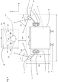
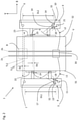
- Figures 1 and 2 show a schematic side view and a schematic top view of an optical measurement system 1 according to embodiments of the present invention.
- one or more contact wires 2a, 2b of an overhead line are depicted for use by trains, trams, trolley busses and the like. These vehicles mechanically engage the one or more contact wires for drawing electric power therefrom, so that the one or more contact wires 2a, 2b are subject to wear and so outer, transverse contours C1, C2 of the one or more contact wires 2a, 2b change over time. For example, due to a pantograph sliding along the one or more contact wires 2a, 2b, the contours C1, C2 may start to flatten as indicated by the flattened contours C1', C2'. Such wear need not be uniform and so the one or more contact wires 2a, 2b may show varying degrees of wear along the overhead line. At some point the one or more contact wires 2a, 2b may be worn to such an extent in that replacement of the one or more contact wires 2a, 2b at particular sections of the overhead line is required to prevent failure.
- an optical measurement system 1 is provided through which outer contours C1, C2, C1', C2' can be accurately determined along any length of the one or more contact wires 2a, 2b even when these contact wires 2a, 2b are still live.
- the one or more contact wires 2a, 2b may change position with respect to a e.g. track T along the overhead line.
- the one or more contact wires 2a, 2b may change position with respect to the track T within a bounding box B.
- the optical measurement system 1 of the present invention needs to be able to track the one or more contact wires 2a, 2b within such a bounding box B along the overhead line.
- a safe upper distance Dsu may be defined between a lower side of the bounding box B and the optical measurement system 1.
- the safe upper distance Dsu may be between 1 and 2 metres, e.g. 1.5 meters.
- the safe upper distance Dsu is in part determined by the voltage on the one or more contact wires 2a, 2b.
- the voltage on the one or more contact wires 2a, 2b is about 1.5 kV in the Netherlands, but higher voltages are conceivable and as such the safe upper distance Dsu increases.
- the safe lower distance Dsl is between 3 to 4 meters, e.g. 3.3 meters.
- the optical measurement system 1 of the present invention is to be mounted on a vehicle V which is arranged to move underneath and along the one or more contact wires 2a, 2b of the overhead line.
- the vehicle V may be a regular train or tram, but a dedicated measurement vehicle V may be used as well.
- a track T is depicted for exemplary purposes, the track T may just as well be a regular road surface, where the vehicle V may then be a trolley bus.
- the optical measurement system 1 comprises an elongated first instrument base 3 and an elongated second instrument base 4, wherein the first instrument base 3 compromises a first mounting member 5 configured for releasable connection to a first side S1 of a vehicle V, and wherein the second instrument base 4 compromises a second mounting member 6 configured for releasable connection to an opposing second side S2 of the vehicle V.
- the vehicle V is capable and arranged for movement underneath the one or more contact wires 2a, 2b of the overhead line.
- first and second instrument bases 3, 4 are releasable mountable to opposing sides S1, S2 (i.e. the side walls)of the vehicle V and not to a roof R thereof, provides for a much wider transverse arrangement of the first and second instrument bases 3, 4 with respect to the one or more contact wires 2a, 2b and as such allow outer contours C1, C2 to be determined over a wider angle, e.g. 120° degrees. This in turn allows for more information on the width/length and height of each contour C1, C2.
- first and second instrument bases 3, 4 are releasable mountable on left and right sides of the roof R of the vehicle, but positioned as far as possible from the one or more contact wires 2a, 2b to obtain a wide transverse arrangement of the first and second instrument bases 3, 4.
- the first instrument base 3 comprises a first laser projector 7 and a first camera assembly 8 longitudinally or lengthwise spaced apart along the first instrument base 3.
- the first instrument base 3 may be seen as an elongated rectangular base configured to extend in longitudinal manner along the vehicle V.
- the first instrument base 3 will extend substantially horizontally along the vehicle V and a such be aligned with the direction of motion of the vehicle V when in use.
- the second instrument base 4 comprises a second laser projector 9 and a second camera assembly 10 longitudinally or lengthwise spaced apart along the second instrument base 4.
- the second instrument base 4 may be seen as an elongated rectangular base configured to extend in longitudinal manner along the vehicle V.
- the second instrument base 4 will extend substantially horizontally along the vehicle V and a such be aligned with the direction of motion of the vehicle.
- the first laser projector 7 and the first camera assembly 8 are longitudinally spaced apart by a distance DL1 which can be chosen so as to achieve good triangulation.
- the second laser projector 9 and the second camera assembly 10 are longitudinally spaced apart by a distance DL2 which can also be chosen so as to achieve good triangulation. It is noted that in an embodiment the distances DL1 and DL2 need not be the same, although from a practical point of view, and without loss of generalisation, the distances DL1 and DL2 may be identical.
- the first camera assembly 8 comprises a first overview camera 11, a first detail camera 12 and a first mirror 13 moveably arranged on the first instrument base 3 in front of the first detail camera 12, and the second camera assembly 10 comprises a second detail camera 14 and a second mirror 15 moveably arranged on the second instrument base 4 in front of the second detail camera 14.
- a processing system 16 see Figure 2 , is provided configured for communication with the first overview camera 11 and the first and second detail camera 12, 14 and/or the first and second mirror 13, 15.
- the processing system 16 may be arranged on the vehicles V and communicatively connected to the first and second instrument base 3, 4 via communication lines L1, L2.
- the first and second laser projector 7, 9 are configured to project a first and second transverse laser line TL1 and TL2, respectively, on the one or more contact wires 2a, 2b.
- the first overview camera 11 is then arranged to capture an overview image above the vehicle V including the one or more contact wires 2a, 2b.
- the processing system 16 is arranged to process the overview image for locating the one or more contact wires 2a, 2b and the processing system is further arranged to control a first position of the first camera 12 or first mirror 13 and a second position of the second camera 14 or second mirror 15 based on the located one or more contact wires 2a, 2b.
- the first detail camera 12 is arranged to capture a first detail image from the first mirror 13 of the projected first and second transverse laser line TL1, TL2 on the one or more contact wires 2a, 2b
- the second detail camera 14 is arranged to capture a second detail image from the second mirror 15 of the projected first and second transverse laser line TL1, TI2 on the one of more contact wire 2a, 2b.
- the optical measurement system 1 in an exemplary embodiment comprises the moveable first and second mirrors 13, 15 to accurately track and capture the projected first and second transverse laser line TL1, TL2 on the one or more contact wires 2a, 2b as the vehicle V is in motion along and underneath the overhead line.
- This allows the first and second detail cameras 12, 14 to remain stationary with respect to the first and second instrument bases 3, 4, respectively, but also allowing the first and second laser projectors 7, 9 to remain stationary with respect to the first and second instrument bases 3, 4.
- first and second movable mirrors 13, 15 reduces the number of components of which motion needs to be controlled for optimal tracking of the one or more contact lines 2a, 2b and in particular the first and second transverse laser lines TL1, TI2 projected thereon.
- the moveable first and second mirror 13, 15 allow for rapid and accurate adjustability in correspondence with a current location of the one or more contact wires 2a, 2b, wherein the first overview camera 11 allows the location of the one or more contact wires 2a, 2b to be determined.
- the first and second mirror 13, 15 accurately track the projected first and second transverse laser lines TL1, TL2 on the one or more contact wires 2a, 2b as the vehicle V moves there along.
- first overview camera 11 in conjunction with the first and second detail cameras 12, 14 allow for a cost effective design as the first and second detail camera 12, 14 need not provide high resolution imaging as they only capture a relatively small area above the vehicle V corresponding to the location of the one or more contact wires 2a, 2b as determined from the first overview camera 11.
- the moveable first and second mirror 13, 15 then reflect an image of this smaller area and project it onto the first and second detail cameras 12, 14. Therefore, the first overview camera 11 allows effective determination of the location of the one or more contact wires 2a, 2b, based on which location the first and second mirror 13, 15 allow for detailed tracking of the one or more contact wires 2a, 2b and the projected first and second transverse laser lines TL1, TL2.
- optical measurement system 1 is configured to be mounted on opposing sides S1, S2 of the vehicle V by virtue of the first and second mounting members 5, 6, allows for a wider viewing angle for imaging the outer contours C1, C2, C1', C2'.
- each of the outer contours C1, C2, C1', C2' of the one or more contact wires 2a, 2b may comprise an arched engagement portion p1 and a grooved mounting portion p2.
- the arched engagement portion p1 is a contour portion that defines a lower part of each of the one or more contact wires 2a, 2b and engages with e.g. the pantograph of a train, tram or trolleybus.
- the grooved mounting portion p2 is a contour portion that defines an upper part of each of the one or more contact wires 2a, 2b and engages a mounting bracket (not shown) at particular locations along the overhead line for suspending the one or more contact wires 2a, 2b above the track T or road.
- the grooved mounting portion p2 is a V-shaped groove which allows each of the one or more contact wires 2a, 2b to be clamped by a mounting bracket (not shown).
- first and second mounting members 5, 6 of the first and second instrument bases 3, 4, respectively allows the optical measurement system 1 to be mounted to opposing sides S1, S2 of the vehicle V and as such allows the projected first and second transverse laser lines TL1, TL2 to extend along the arched engagement portion p1 of the lower part of each of the one or more contact wires 2a, 2b as well as the grooved mounting portion p2 of the upper part each of the one or more contact wires 2a, 2b.
- each of the one or more contact wires 2a, 2b By allowing the grooved mounting portion p2 of each of the one or more contact wires 2a, 2b to be observable by the first and second detail cameras 12, 14 provides for a reference contour that does not significantly wear and change over time. Such a reference contour may then be used to improve accuracy and reliability at which each of the one or more contact wires 2a, 2b can be measured by analysing the arched contour portion p1 and by taking into account the grooved mounting portion p2 as a reference contour.
- the first overview camera 11 is arranged and configured to capture an overview image of the one or more contact wires 2a, 2b above the vehicle V.
- the processing system 16 is then arranged to process the overview image for locating the one or more contact wires 2a, 2b, and in particular the first and second transverse laser lines TL1, TL2 projected thereon.
- the processing system 16 further allows control of a first position of the first mirror 13 and a second position of the second mirror 15 based on the located one or more contact wires 2a, 2b. Once positioned accordingly, the first and second mirrors 13, 15 reflect an image of the first and second transverse laser lines TL1, TL2 to the first and second detail cameras 12, 14.
- the first overview camera 11 and the first and second detail cameras 12, 14 allow for a two stage tracking process wherein, in a first stage, the first overview camera 11 is configured to capture an overview image of a large area including the bounding box B above the vehicle V.
- the processing system 16 is then configured to determine the location of the one or more contact wires 2a, 2b, including the first and second transverse laser lines TL1, TL2. Based on this overview image, in a second stage, the processing system 16 is configured to control the first and second mirror 13, 15 for allowing a detail image to be capture of the first and second transverse laser lines TL1, TL2 by the first and second detail cameras 12, 14.
- the first and second detail cameras 12, 14 are configured to simultaneously capture a detail image.
- Such a two stage image process may be achieved by an embodiment wherein the first overview camera 11 has a field of view ⁇ 1 larger than a field of view ⁇ 2 of the first and second detail camera 12, 14.
- the larger field of view ⁇ 1 of the first overview camera 11 allows for a larger area above the vehicle V to be captured whilst the smaller field of view ⁇ 2 of the first and second detail camera 12, 14 allows for a smaller area to be captured. Because of the smaller area captured by the first and second detail cameras 12, 14, it is still possible to get a sufficiently high resolution image of the first and second transverse laser lines TL1, TL2 even though the first and second detail cameras 12, 14 need not exhibit high resolution imaging capability.
- the field of view ⁇ 1 of the first overview camera 11 is between 40° and 50° degrees, e.g. 45° degrees, and wherein the field of view ⁇ 2 of the first and second detail cameras 12, 14 is smaller than 40° degrees.
- the first camera assembly 8 comprises a third detail camera 17 and optionally a third mirror 18 moveably arranged on the first instrument base 3 in front of the third detail camera 17, and the second camera assembly 10 comprises a fourth detail camera 19 and optionally a fourth mirror 20 moveably arranged on the second instrument base 4 in front of the fourth detail camera 19.
- the processing system 16 is further configured for communication with the third and fourth detail camera 17, 19 and/or the third and fourth mirror 18, 20 also.
- the processing system 16 is further arranged to e.g. control a third position of the third detail camera 17/ third mirror 18 and a fourth position of the fourth detail camera 19/ fourth mirror 20 based on the located one or more contact wires 2a, 2b.
- the third detail camera 17 is arranged to capture a third detail image from the third mirror 18 of the projected first and second transverse laser line TL1, TL2, on the one or more contact wires 2a, 2b
- the fourth detail camera 19 is arranged to capture a fourth detail image from the fourth mirror 20 of the projected first and second transverse laser line on the one of more contact wire 2a, 2b.
- the first and second camera assemblies 8, 10 each comprise a pair of detail cameras, i.e. the first and third detail camera 12, 17 on the first instrument base 3 and the second and fourth detail camera 14, 19 on the second instrument base 4.
- each of the first and second instrument bases 3, 4 By utilizing a pair of detail cameras on each of the first and second instrument bases 3, 4 it is possible to combine captured images of each pair of detail cameras to achieve even higher accuracy when determining the outer contours C1, C2, C1', C2'. Also, by utilizing a pair of detail cameras on each of the first and second instrument bases 3, 4, it is possible to improve tracking of the position and the orientation of the first and second transverse laser lines TL1, TL2.
- the above embodiment allows for four (4) images each of which comprises the first and second transverse laser lines TL1, TL2 and wherein these four (4) images can be combined to achieve highly accurate measurements of the outer contours C1, C2, C1', C2' of the one or more contact wires 2a, 2b.
- the second camera assembly 10 of the second instrument base 4 may comprises a second overview camera 21. This provides further image data on the area above the vehicle V so that through combining captured images from the first and second overview cameras 11, 21 the location of the one or more contact wires 2a, 2b can be determined more accurately and reliably.
- the third and fourth detail cameras 17, 19 may have the same or similar field of view ⁇ 2 as the first and second detail camera 12, 14. So in this case the field of view ⁇ 1 of the first overview camera 11 is also larger than the field of view ⁇ 2 of the third and fourth detail camera 17, 19.
- the field of view ⁇ 1 of the second overview camera 21 is larger than the field of view ⁇ 2 of the first and second detail cameras 12, 14 and/or the third and the fourth detail camera 17, 19.
- the first overview camera 11 is a black and white camera, which provides improved contrast of the one or more contact wires 2a, 2b in a captured image thereof with respect to other features in the captured image.
- the second overview camera 21 may be a colour camera, thereby facilitating further image analysis on various coloured features to achieve accurate and reliable determination of the location of the one or more contact wires 2a, 2b.
- neither the first overview camera 11 nor the second overview camera 21 need to be placed centrally on the roof R of vehicle V, thereby making the optical measurement system 1 further vehicle independent and allows for further simplicity when mounting and demounting the measurement system 1.
- the elongated first instrument base 3 comprises the first mounting member 5 configured for releasable connection to the first side S1 of the vehicle V
- the elongated second instrument base 4 comprises the second mounting member 6 configured for releasable connection to the opposing second side S2 of the vehicle V.
- the optical measurement system 1 further comprises an elongated first and an elongated second rail member 22, 23 each being configured for being mounted to the first and second side S1, S2 of the vehicle V, respectively, and wherein the first and second mounting member 5, 6 are configured for releasable connection to the first and second rail member 22, 23, respectively.
- first and second rail member22, 23 can be positioned on the vehicle V and may, but need not, remain permanently on the vehicle V.
- first and second rail member 22, 23 are mounted to the vehicle V, the first and second instrument bases 3, 4 are easily attached by virtue of the releasable first and second mounting members 5, 6. In doing so the alignment of the first and second instrument bases 3, 4 is ensured and very little further work is required by users mounting the optical measurement system 1.
- first and second mounting member 5, 6 are configured for moveable (e.g. sliding) engagement along the first and second rail member 22, 23 respectively, wherein the first and second rail member 22, 23 comprise a first and a second adjustable blocking member 24, 25, respectively, for abutment with the first and second mounting member 5, 6, respectively.
- This embodiment is advantageous as it allows the first and second instrument bases 3, 4 to be accurately positioned in reproducible manner in longitudinal direction as depicted in Figure 2 .
- the first and second instrument bases 3, 4 can be mounted accurately in repeatable manner once the first and second blocking members 24, 25 are positioned as desired.
- the first and second adjustable blocking members 24, 25 allow the first and second instrument bases 3, 4 to be longitudinal offset by an offset distance Do as shown in Figure 2 . This in turn allows the first and second laser projector 7, 9 to be longitudinally offset by the offset distance Do. As a result, the projected first and second transverse laser lines TL1, TL2 are offset by the offset distance Do.
- first and second transverse laser lines TL1, TL2 at an offset distance Do allows for more accurate determination of the outer contours C1, C2, C1', C2' of the one or more contact wires 2a, 2b.
- the overhead line comprises a plurality of contact wires 2a, 2b is it advantageous to place the first and second instrument bases 3, 4 at the offset distance Do and a such offset the first and second transverse laser lines TL1, TL2 to achieve increased measurement diversity and further information to accurately determine the outer contours C1, C2, C1', C2'.
- the offset distance Do is less than 3 cm at which the projected first and second transverse laser lines TL1, TL2 are still considered to represent a single location on the one or more contact wires 2a, 2b and a such are combined to determine a single outer contour representative of the one or more contact wires 2a, 2b.
- the optical measurement system 1 is active when the vehicle V is moving along the track T so that a particular length of the one or more contact wires 2a, 2b can be investigated on wear and various geometric properties.
- the first and second camera assemblies 8 and 10 each have a maximum imaging throughput of about 500 images per second, then a speed of 54 km/h of the vehicle V corresponds to an image sample distance of about 3 cm along the one or more contact wires 2a, 2b.
- the first and second laser projector 7, 9 may each exhibit a projection angel ⁇ 1, ⁇ 2 between 30° and 40° degrees, e.g. 35°, so that the projected first and second transverse laser lines TL1, TL2 will span the bounding box B and as such cover all possible positions of the one or more contact wires 2a, 2b in the bounding box B.
- first and the second instrument base 3, 4 are configured to be positioned at an inward angle ⁇ 1, ⁇ 2 between 30° and 40° degrees (measured from vertical) in the mounted state of the first and second instrument bases 3, 4.
- This embodiment facilitates visibility of the grooved mounting portion p2 to be used as a reference contour for determining the outer contours C1, C2, C1', C2'.
- the first and the second laser projector 7, 9 are each configured for projecting blue laser light, e.g. laser light having a wavelength between 380-500 nm. Utilizing shorter wavelength in the visible spectrum allows not only for higher resolution imaging, but also reduces measurement sensitivity to sunlight during the day. Furthermore, blue laser light has better reflection from the one or more contact wires 2a, 2b.
- each of the first and second laser projector 7, 9 exhibits an output power of more than about 400 mW, e.g. 500 mW, to allow for sufficient intensity and clear projected first and second transverse laser lines TL1, TL2 on the one or more contact wires 2a, 2b.
- the first and second detail cameras 12, 14 are each provided with a narrow band filter element 12a, 14a in correspondence with the blue light spectrum, thereby filtering out non-relevant light spectra.
- This embodiment can be further extended wherein the first and second detail cameras 12, 14 are each provided with a narrow band filter element 12a, 14a in correspondence with the blue light spectrum, and wherein the third and fourth detail cameras 17, 19 are each provided with a narrow band filter element 17a, 19a in correspondence with the blue light spectrum.
- a method of mounting the optical measurement system 1 to the vehicle V can now be explained, in particular in regard on allowing for the aforementioned offset distance Do for achieving two parallel first and second transverse laser lines TL1, TL2 on the one or more contact wires 2a, 2b.
- the method comprises the steps of connecting the first mounting member 5 of the first instrument base 3 to the first side S1 of the vehicle V and connecting the second mounting member 6 of second instrument base 4 to the second side S2 of the vehicle V such that the first laser projector 6 and the second laser projector 9 are offset in longitudinal direction over the offset distance Do.
- the method comprises connecting the first rail member 22 to the first side S1 of the vehicle V and connecting the second rail member 23 to the second side S2 of the vehicle V, and then connecting the first mounting member 5 of the first instrument base 3 to the first rail member 22 and connecting the second mounting member 6 of the second instrument base 4 to the second rail member 23, and moving (e.g. sliding) the first and/or the second instrument base 3, 4 along the first and/or the second rail member 22, 23 for obtaining the offset distance Do.
- the offset distance (Do) is smaller than 3 cm.
Landscapes
- Engineering & Computer Science (AREA)
- Physics & Mathematics (AREA)
- General Physics & Mathematics (AREA)
- Manufacturing & Machinery (AREA)
- Mechanical Engineering (AREA)
- Computer Vision & Pattern Recognition (AREA)
- Length Measuring Devices By Optical Means (AREA)
Abstract
Description
- The present invention relates to an optical measurement system for an overhead line, in particular an optical measurement system for determining outer contours of one or more contact wires of an overhead line used by trains, trams, trolleybuses and the like.
- European
patent application EP 3 051 252 A1 discloses a trolley wire measurement apparatus for measurement of wearing portions of a trolley wire from a traveling car. The trolley wire measurement apparatus comprises a first trolley wire measuring instrument on a rotating stage provided on a left-hand side of a car, and a second trolley wire measuring instrument on a rotating stage provided on a right-hand side of the car. Between the first and second trolley wire measuring instrument there is provided a trolley wire height and deviation detector arranged near the centre of the car. Each of the first and second trolley wire measuring instruments comprises a light emitting (or projection) unit and a light receiving unit, wherein the light emitting unit converts a monochromatic light having a specific wavelength within a range of infrared light into a strip slit light by function of a light emitting lens, thereby irradiating the trolley wire. Each light receiving unit receives a reflection guided from the trolley wire through an image forming lens. The trolley wire height and deviation detector, being constructed by a laser measuring sensor, is provided on a roof of the car, wherein the trolley wire height and deviation detector receives reflection light from the trolley wire above the roof of the car while scanning laser light in the direction of deviation of the trolley wire, thereby measuring a distance and an angle defined between the laser measuring sensor and the trolley wire. - The present invention seeks to provide an improved optical measurement system for determining outer contours of one or more contact wires of an overhead line, where the measurement system is less sensitive to vibration and allows for increased speed and accuracy at which the outer contours of the one or more contact wires can be observed and analysed. The measurement system can be readily (retro)fitted to any desired vehicle for movement underneath the one or more contact wires. Furthermore, the measurement system allows for taking accurate measurements during the day or night whilst the one or more contact wires remain live.
- According to the present invention, an optical measurement system for determining outer contours of one or more contact wires of an overhead line is provided, comprising
an elongated first instrument base and an elongated second instrument base, wherein the first instrument base compromises a first mounting member configured for releasable connection to a first side of a vehicle, and wherein the second instrument base compromises a second mounting member configured for releasable connection to an opposing second side of the vehicle, wherein the vehicle is arranged for movement underneath the one or more contact wires of the overhead line. - The first instrument base comprises a first laser projector and a first camera assembly longitudinally spaced apart along the first instrument base, and wherein the second instrument base comprises a second laser projector and a second camera assembly longitudinally spaced apart along the second instrument base.
- The first camera assembly comprises a first overview camera, a first detail camera and a first mirror moveably arranged on the first instrument base in front of the first detail camera, and wherein the second camera assembly comprises a second detail camera and a second mirror moveably arranged on the second instrument base in front of the second detail camera.
- The optical measurement system further comprises a processing system configured for communication with the first overview camera and the first and second mirror;
wherein, in a mounted state of the first and second instrument base on the first side and second side of the vehicle, respectively, the first and second laser projector are configured to project a first and second transverse laser line, respectively, on the one or more contact wires;
wherein the first overview camera is arranged to capture an overview image of the one or more contact wires;
wherein the processing system is arranged to process the overview image for locating the one or more contact wires, and wherein the processing system is further arranged to control a first position of the first mirror and a second position of the second mirror based on the located one or more contact wires, and
wherein the first detail camera is arranged to capture a first detail image from the first mirror of the projected first and second transverse laser lines on the one or more contact wires, and wherein the second detail camera is arranged to capture a second detail image from the second mirror of the projected first and second transverse laser lines on the one of more contact wires. - According to the present invention, the optical measurement system provides the moveable first and second mirrors to accurately track and capture the projected first and second transverse laser line on the one or more contact wires as the vehicle is in motion along and underneath the overhead line.
- In contrast to the prior art, by utilizing the first and second movable mirrors reduces the number of components of which motion needs to be controlled for optimal tracking of the one or more contact lines and the first and second transverse laser lines projected thereon. The moveable first and second mirror allow for rapid and accurate adjustability in correspondence with the location of the one or more contact wires, wherein the first overview camera allows the location of the one or more contact wires to be determined, based on which the first and second mirror allows accurate, detailed tracking of the projected first and second transverse laser lines on the one or more contact wires.
- Furthermore, the first overview camera in conjunction with the first and second detail cameras allow for a cost effective design as the first and second detail camera need not provide high resolution imaging as they only capture a relatively small area above the vehicle corresponding to location of the one or more contact wires. When installed, the moveable first and second mirror reflect an image of this smaller area and project/reflect it onto the first and second detail cameras. Therefore, the first overview camera allows effective determination of the location of the one or more contact wires and the projected first and second transverse laser lines thereon. Based on the determined location, the first and second mirror allow for detailed tracking of the one or more contact wires and the projected first and second transverse laser lines thereon. By combining the projected first and second transverse laser lines captured by both the first and the second detail camera, an accurate outer contour of each of the one or more contact wires can be obtained, which in turn allows for wear and various geometric properties of the contact wires to be determined.
- The present invention will be discussed in more detail below, with reference to the attached drawings, in which
-
Figure 1 shows a schematic side view of an optical measurement system according to an embodiment of the present invention. -
Figure 2 shows a schematic top view of an optical measurement system according to an embodiment of the present invention. -
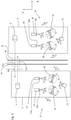
Figure 3 shows a schematic partial top view of an optical measurement system according to an embodiment of the present invention. -
Figures 1 and2 show a schematic side view and a schematic top view of anoptical measurement system 1 according to embodiments of the present invention. - In these figures one or
more contact wires more contact wires more contact wires more contact wires more contact wires more contact wires more contact wires - According to the present invention, to monitor the evolution of wear of the one or
more contact wires optical measurement system 1 is provided through which outer contours C1, C2, C1', C2' can be accurately determined along any length of the one ormore contact wires contact wires - It is important note that in real world scenarios the one or
more contact wires Figure 1 , the one ormore contact wires - Therefore, the
optical measurement system 1 of the present invention needs to be able to track the one ormore contact wires - Another important point to note is that, according to regulations, the
optical measurement system 1 may need to remain at a safe distance from the one ormore contact wire optical measurement system 1. In an exemplary embodiment, the safe upper distance Dsu may be between 1 and 2 metres, e.g. 1.5 meters. Logically, the safe upper distance Dsu is in part determined by the voltage on the one ormore contact wires more contact wires - There can also be defined a safe lower distance Dsl as measured from the track T upward. The
optical measurement system 1 is then to remain below the safe lower distance Dsl when the one ormore contact wires - The
optical measurement system 1 of the present invention is to be mounted on a vehicle V which is arranged to move underneath and along the one ormore contact wires optical measurement system 1 may be mounted has a width Wv between 2 and 2.5 meters and a height Hv between 3 and 3.5 meters, e.g. Wv = 2.1 meters, Hv = 3.1 meters. - According to the present invention, the
optical measurement system 1 comprises an elongatedfirst instrument base 3 and an elongatedsecond instrument base 4, wherein thefirst instrument base 3 compromises afirst mounting member 5 configured for releasable connection to a first side S1 of a vehicle V, and wherein thesecond instrument base 4 compromises asecond mounting member 6 configured for releasable connection to an opposing second side S2 of the vehicle V. As stated earlier, the vehicle V is capable and arranged for movement underneath the one ormore contact wires - As will be discussed in further detail below, in an exemplary embodiment the first and
second instrument bases second instrument bases more contact wires second instrument bases more contact wires second instrument bases - As depicted in
Figure 2 , thefirst instrument base 3 comprises afirst laser projector 7 and afirst camera assembly 8 longitudinally or lengthwise spaced apart along thefirst instrument base 3. Here, thefirst instrument base 3 may be seen as an elongated rectangular base configured to extend in longitudinal manner along the vehicle V. In an embodiment, thefirst instrument base 3 will extend substantially horizontally along the vehicle V and a such be aligned with the direction of motion of the vehicle V when in use. - The
second instrument base 4 comprises asecond laser projector 9 and asecond camera assembly 10 longitudinally or lengthwise spaced apart along thesecond instrument base 4. Here, thesecond instrument base 4 may be seen as an elongated rectangular base configured to extend in longitudinal manner along the vehicle V. In an embodiment, thesecond instrument base 4 will extend substantially horizontally along the vehicle V and a such be aligned with the direction of motion of the vehicle. - As depicted, the
first laser projector 7 and thefirst camera assembly 8 are longitudinally spaced apart by a distance DL1 which can be chosen so as to achieve good triangulation. Likewise, thesecond laser projector 9 and thesecond camera assembly 10 are longitudinally spaced apart by a distance DL2 which can also be chosen so as to achieve good triangulation. It is noted that in an embodiment the distances DL1 and DL2 need not be the same, although from a practical point of view, and without loss of generalisation, the distances DL1 and DL2 may be identical. - With further reference to the exemplary embodiment of
Figure 3 , showing a schematic partial top view of theoptical measurement system 1 without the vehicle, thefirst camera assembly 8 comprises afirst overview camera 11, afirst detail camera 12 and afirst mirror 13 moveably arranged on thefirst instrument base 3 in front of thefirst detail camera 12, and thesecond camera assembly 10 comprises asecond detail camera 14 and asecond mirror 15 moveably arranged on thesecond instrument base 4 in front of thesecond detail camera 14. - A
processing system 16, seeFigure 2 , is provided configured for communication with thefirst overview camera 11 and the first andsecond detail camera second mirror processing system 16 may be arranged on the vehicles V and communicatively connected to the first andsecond instrument base - In a mounted state of the first and
second instrument base second laser projector more contact wires first overview camera 11 is then arranged to capture an overview image above the vehicle V including the one ormore contact wires processing system 16 is arranged to process the overview image for locating the one ormore contact wires first camera 12 orfirst mirror 13 and a second position of thesecond camera 14 orsecond mirror 15 based on the located one ormore contact wires first detail camera 12 is arranged to capture a first detail image from thefirst mirror 13 of the projected first and second transverse laser line TL1, TL2 on the one ormore contact wires second detail camera 14 is arranged to capture a second detail image from thesecond mirror 15 of the projected first and second transverse laser line TL1, TI2 on the one ofmore contact wire - The
optical measurement system 1 in an exemplary embodiment comprises the moveable first andsecond mirrors more contact wires second detail cameras second instrument bases second laser projectors second instrument bases - It is worth noting that in contrast to the prior art systems, by utilizing the first and second
movable mirrors more contact lines second mirror more contact wires first overview camera 11 allows the location of the one ormore contact wires second mirror more contact wires - It is further noted that the
first overview camera 11 in conjunction with the first andsecond detail cameras second detail camera more contact wires first overview camera 11. The moveable first andsecond mirror second detail cameras first overview camera 11 allows effective determination of the location of the one ormore contact wires second mirror more contact wires first detail camera 12 and thesecond detail camera 14, accurate outer contours C1, C2, C1', C2' of the one ormore contact wires more contact wires - Since the
optical measurement system 1 is configured to be mounted on opposing sides S1, S2 of the vehicle V by virtue of the first and second mountingmembers - In particular, as depicted in
Figure 1 , each of the outer contours C1, C2, C1', C2' of the one ormore contact wires more contact wires more contact wires more contact wires Figure1 , in an exemplary embodiment the grooved mounting portion p2 is a V-shaped groove which allows each of the one ormore contact wires - By virtue of the first and second mounting
members second instrument bases optical measurement system 1 to be mounted to opposing sides S1, S2 of the vehicle V and as such allows the projected first and second transverse laser lines TL1, TL2 to extend along the arched engagement portion p1 of the lower part of each of the one ormore contact wires more contact wires - By allowing the grooved mounting portion p2 of each of the one or
more contact wires second detail cameras more contact wires - As mentioned earlier, the
first overview camera 11 is arranged and configured to capture an overview image of the one ormore contact wires processing system 16 is then arranged to process the overview image for locating the one ormore contact wires processing system 16 further allows control of a first position of thefirst mirror 13 and a second position of thesecond mirror 15 based on the located one ormore contact wires second mirrors second detail cameras - Therefore, in view of the above, the
first overview camera 11 and the first andsecond detail cameras first overview camera 11 is configured to capture an overview image of a large area including the bounding box B above the vehicle V. Theprocessing system 16 is then configured to determine the location of the one ormore contact wires processing system 16 is configured to control the first andsecond mirror second detail cameras second detail cameras - Such a two stage image process may be achieved by an embodiment wherein the
first overview camera 11 has a field of view γ1 larger than a field of view γ2 of the first andsecond detail camera first overview camera 11 allows for a larger area above the vehicle V to be captured whilst the smaller field of view γ2 of the first andsecond detail camera second detail cameras second detail cameras - In an exemplary embodiment, the field of view γ1 of the
first overview camera 11 is between 40° and 50° degrees, e.g. 45° degrees, and wherein the field of view γ2 of the first andsecond detail cameras first overview camera 11 to capture sufficient detail of a large area above the vehicle V for locating the one ormore contact wires second detail cameras - As further depicted in
Figure 2 and3 , in an embodiment thefirst camera assembly 8 comprises athird detail camera 17 and optionally athird mirror 18 moveably arranged on thefirst instrument base 3 in front of thethird detail camera 17, and thesecond camera assembly 10 comprises afourth detail camera 19 and optionally afourth mirror 20 moveably arranged on thesecond instrument base 4 in front of thefourth detail camera 19. Theprocessing system 16 is further configured for communication with the third andfourth detail camera fourth mirror - In the mounted state of the first and
second instrument base processing system 16 is further arranged to e.g. control a third position of thethird detail camera 17/third mirror 18 and a fourth position of thefourth detail camera 19/fourth mirror 20 based on the located one ormore contact wires third detail camera 17 is arranged to capture a third detail image from thethird mirror 18 of the projected first and second transverse laser line TL1, TL2, on the one ormore contact wires fourth detail camera 19 is arranged to capture a fourth detail image from thefourth mirror 20 of the projected first and second transverse laser line on the one ofmore contact wire second camera assemblies third detail camera first instrument base 3 and the second andfourth detail camera second instrument base 4. - By utilizing a pair of detail cameras on each of the first and
second instrument bases second instrument bases - The above embodiment allows for four (4) images each of which comprises the first and second transverse laser lines TL1, TL2 and wherein these four (4) images can be combined to achieve highly accurate measurements of the outer contours C1, C2, C1', C2' of the one or
more contact wires - In an advantageous embodiment, the
second camera assembly 10 of thesecond instrument base 4 may comprises asecond overview camera 21. This provides further image data on the area above the vehicle V so that through combining captured images from the first andsecond overview cameras more contact wires - It is noted that in an embodiment the third and
fourth detail cameras second detail camera first overview camera 11 is also larger than the field of view γ2 of the third andfourth detail camera - Likewise, in an embodiment, the field of view γ1 of the
second overview camera 21 is larger than the field of view γ2 of the first andsecond detail cameras fourth detail camera - To improve accuracy in determining the location of the one or
more contact wires first overview camera 11 is a black and white camera, which provides improved contrast of the one ormore contact wires - In an advantageous embodiment, the
second overview camera 21 may be a colour camera, thereby facilitating further image analysis on various coloured features to achieve accurate and reliable determination of the location of the one ormore contact wires - In contrast to the prior art, neither the
first overview camera 11 nor thesecond overview camera 21 need to be placed centrally on the roof R of vehicle V, thereby making theoptical measurement system 1 further vehicle independent and allows for further simplicity when mounting and demounting themeasurement system 1. - Referring to
Figure 1 , as mentioned earlier the elongatedfirst instrument base 3 comprises the first mountingmember 5 configured for releasable connection to the first side S1 of the vehicle V, and wherein the elongatedsecond instrument base 4 comprises the second mountingmember 6 configured for releasable connection to the opposing second side S2 of the vehicle V. - To facilitate alignment accuracy with respect to the vehicle V and alignment accuracy between the first and
second instrument bases optical measurement system 1 further comprises an elongated first and an elongatedsecond rail member member second rail member - In this embodiment, the first and second rail member22, 23 can be positioned on the vehicle V and may, but need not, remain permanently on the vehicle V. Once the first and
second rail member second instrument bases members second instrument bases optical measurement system 1. - In an advantageous embodiment, the first and second mounting
member second rail member second rail member member member - This embodiment is advantageous as it allows the first and
second instrument bases Figure 2 . In particular, through the first andsecond rail members second blocking members second instrument bases second blocking members - The first and second adjustable blocking
members second instrument bases Figure 2 . This in turn allows the first andsecond laser projector - By having the first and second transverse laser lines TL1, TL2 at an offset distance Do allows for more accurate determination of the outer contours C1, C2, C1', C2' of the one or
more contact wires contact wires second instrument bases - In an exemplary embodiment the offset distance Do is less than 3 cm at which the projected first and second transverse laser lines TL1, TL2 are still considered to represent a single location on the one or
more contact wires more contact wires - It is worth noting that the
optical measurement system 1 is active when the vehicle V is moving along the track T so that a particular length of the one ormore contact wires second camera assemblies more contact wires - Referring to
Figure 1 , in an exemplary embodiment the first andsecond laser projector more contact wires - In a further advantageous embodiment, the first and the
second instrument base second instrument bases - To further facilitate accurate determination of the outer contours C1, C2, C1', C2', an embodiment is provided wherein the first and the
second laser projector more contact wires - In an advantageous embodiment, each of the first and
second laser projector more contact wires - To further increase measurement accuracy, the first and
second detail cameras band filter element second detail cameras band filter element fourth detail cameras band filter element - In a further aspect, a method of mounting the
optical measurement system 1 to the vehicle V can now be explained, in particular in regard on allowing for the aforementioned offset distance Do for achieving two parallel first and second transverse laser lines TL1, TL2 on the one ormore contact wires member 5 of thefirst instrument base 3 to the first side S1 of the vehicle V and connecting the second mountingmember 6 ofsecond instrument base 4 to the second side S2 of the vehicle V such that thefirst laser projector 6 and thesecond laser projector 9 are offset in longitudinal direction over the offset distance Do. - Achieving the offset distance Do is greatly simplified when the first and
second rail member first rail member 22 to the first side S1 of the vehicle V and connecting thesecond rail member 23 to the second side S2 of the vehicle V, and then connecting the first mountingmember 5 of thefirst instrument base 3 to thefirst rail member 22 and connecting the second mountingmember 6 of thesecond instrument base 4 to thesecond rail member 23, and moving (e.g. sliding) the first and/or thesecond instrument base second rail member - The present invention embodiments, as described above with reference to a number of exemplary embodiments, can also be summarized by the following numbered and interdependent embodiment clauses:
-
Embodiment 1. An optical measurement system (1) for determining outer contours of one or more contact wires (2a, 2b) of an overhead line, comprising
an elongated first instrument base (3) and an elongated second instrument base (4), wherein the first instrument base (3) compromises a first mounting member (5) configured for releasable connection to a first side (S1) of a vehicle (V), and wherein the second instrument base (4) compromises a second mounting member (6) configured for releasable connection to an opposing second side (S2) of the vehicle (V), wherein the vehicle (V) is arranged for movement underneath the one or more contact wires (2a, 2b) of the overhead line;
wherein the first instrument base (3) comprises a first laser projector (7) and a first
camera assembly (8) longitudinally spaced apart along the first instrument base (3), and wherein the second instrument base (4) comprises a second laser projector (9) and a second camera assembly (10) longitudinally spaced apart along the second instrument base (4);
wherein the first camera assembly (8) comprises a first overview camera (11), and a first detail camera (12) moveably arranged on the first instrument base (3), and wherein the second camera assembly (10) comprises a second detail camera (14) moveably arranged on the second instrument base (4); and further comprising
a processing system (16) configured for communication with the first overview camera (11) and the first and second detail camera (12, 14);
wherein, in a mounted state of the first and second instrument base (3, 4) on the first side (S1) and second side (S2) of the vehicle (V), respectively, the first and second laser projector (7, 9) are configured to project a first and second transverse laser line (TL1, TL2), respectively, on the one or more contact wires (2a, 2b);
wherein the first overview camera (11) is arranged to capture an overview image of the one or more contact wires (2a);
wherein the processing system (16) is arranged to process the overview image for locating the one or more contact wires (2a, 2b), and wherein the processing system (16) is further arranged to control a first position of the first detail camera (12) and a second position of the second detail camera (14) based on the located one or more contact wires (2a, 2b), and
wherein the first detail camera (12) is arranged to capture a first detail image of the projected first and second transverse laser lines (TL1, TL2) on the one or more contact wires (2a, 2b), and wherein the second detail camera (14) is arranged to capture a second detail image of the projected first and second transverse laser lines (TL1, TL2) on the one of more contact wires (2a, 2b). -
Embodiment 2. The optical measurement system according toembodiment 1, wherein the first overview camera (11) has a field of view (yl) larger than a field of view (y2) of the first and second detail camera (12, 14). -
Embodiment 3. The optical measurement system according toembodiment 2, wherein the field of view (yl) of the first overview camera (11) is between 40° and 50°, and wherein the field of view (y2) of the first and second detail cameras (12, 14) is smaller than 40°. -
Embodiment 4. The optical measurement system according to any one of embodiments 1-3, wherein the first camera assembly (8) comprises a third detail camera (17) moveably arranged on the first instrument base (3), and wherein the second camera assembly (10) comprises a fourth detail camera (19) moveably arranged on the second instrument base (4);
wherein the processing system (16) is further configured for communication with the third and fourth detail camera (17, 19);
wherein, in the mounted state of the first and second instrument base (3, 4), the processing system (16) is further arranged to control a third position of the third detail camera (17) and a fourth position of the fourth detail camera (19) based on the located one or more contact wires (2a, 2b), and
wherein the third detail camera (17) is arranged to capture a third detail image of the projected first and second transverse laser line (TL1, TL2) on the one or more contact wires (2a, 2b), and wherein the fourth detail camera (19) is arranged to capture a fourth detail image of the projected first and second transverse laser line (TL1, TL2) on the one of more contact wires (2a, 2b). -
Embodiment 5. The optical measurement system according to any one of embodiments 1-4, wherein the first overview camera (11) is a black and white camera. -
Embodiment 6. The optical measurement system according to any one of embodiments 1-5, wherein the second camera assembly (10) of the second instrument base (4) further comprises a second overview camera (21). -
Embodiment 7. The optical measurement system according toembodiment 6, wherein the second overview camera (21) is a colour camera. -
Embodiment 8. The optical measurement system according to any one of embodiments 1-7, further comprising an elongated first and an elongated second rail member (22, 23) each being configured for being mounted to the first and second side (S1, S2) of the vehicle (V), respectively, and wherein the first and second mounting member (5, 6) are configured for releasable connection to the first and second rail member (22, 23), respectively. -
Embodiment 9. The optical measurement system according toembodiment 8, wherein the first and second mounting member (5, 6) are configured for moveable engagement along the first and second rail member (22, 23) respectively, wherein the first and second rail member (22, 23) comprise a first and a second adjustable blocking member (24, 25), respectively, for abutment with the first and second mounting member (5, 6), respectively. -
Embodiment 10. The optical measurement system according to any one of embodiments 1-9, wherein the first and the second laser projector (7, 9) are configured for projecting blue laser light having a wave length between 380 and 500 nm. -
Embodiment 11. The optical measurement system according toembodiment 10, wherein each of the first and second laser projector (7, 9) exhibit an output power of more than 400 mW.Embodiment 12. The optical measurement system according toembodiment -
Embodiment 13. The optical measurement system according to any one of embodiments 1-12, wherein the first and the second instrument base (3, 4) are configured to be positioned at an inward angle (α1, α2) between 30° and 40° in the mounted state of the first and second instrument base (3, 4). -
Embodiment 14. A method of mounting the optical measurement system (1) according to any one of embodiments 1-13 to a vehicle (V) arranged for movement underneath one or more contact wires (2a, 2b), comprising:- connecting the first mounting member (5) of the first instrument base (3) to a first side (S1) of the vehicle (V),
connecting the second mounting member (6) of the second instrument base (4) to a second side (S2) of the vehicle (V), such that the first laser projector (7) and the second laser projector (9) are offset in longitudinal direction over an offset distance (Do).
- connecting the first mounting member (5) of the first instrument base (3) to a first side (S1) of the vehicle (V),
-
Embodiment 15. The method according toembodiment 14, wherein the offset distance (Do) is smaller than 3 cm. - The present invention has been described above with reference to a number of exemplary embodiments as shown in the drawings. Modifications and alternative implementations of some parts or elements are possible, and are included in the scope of protection as defined in the appended claims.
Claims (15)
- An optical measurement system (1) for determining outer contours of one or more contact wires (2a, 2b) of an overhead line, comprising
an elongated first instrument base (3) and an elongated second instrument base (4), wherein the first instrument base (3) compromises a first mounting member (5) configured for releasable connection to a first side (S1) of a vehicle (V), and wherein the second instrument base (4) compromises a second mounting member (6) configured for releasable connection to an opposing second side (S2) of the vehicle (V), wherein the vehicle (V) is arranged for movement underneath the one or more contact wires (2a, 2b) of the overhead line;
wherein the first instrument base (3) comprises a first laser projector (7) and a first camera assembly (8) longitudinally spaced apart along the first instrument base (3), and wherein the second instrument base (4) comprises a second laser projector (9) and a second camera assembly (10) longitudinally spaced apart along the second instrument base (4);
wherein the first camera assembly (8) comprises a first overview camera (11), a first detail camera (12) and a first mirror (13) moveably arranged on the first instrument base (3) in front of the first detail camera (12), and wherein the second camera assembly (10) comprises a second detail camera (14) and a second mirror (15) moveably arranged on the second instrument base (4) in front of the second detail camera (14); and further comprising
a processing system (16) configured for communication with the first overview camera (11) and the first and second mirror (13, 15);
wherein, in a mounted state of the first and second instrument base (3, 4) on the first side (S1) and second side (S2) of the vehicle (V), respectively, the first and second laser projector (7, 9) are configured to project a first and second transverse laser line (TL1, TL2), respectively, on the one or more contact wires (2a, 2b);
wherein the first overview camera (11) is arranged to capture an overview image of the one or more contact wires (2a);
wherein the processing system (16) is arranged to process the overview image for locating the one or more contact wires (2a, 2b), and wherein the processing system (16) is further arranged to control a first position of the first mirror (13) and a second position of the second mirror (15) based on the located one or more contact wires (2a, 2b), and
wherein the first detail camera (12) is arranged to capture a first detail image from the first mirror (13) of the projected first and second transverse laser lines (TL1, TL2) on the one or more contact wires (2a, 2b), and wherein the second detail camera (14) is arranged to capture a second detail image from the second mirror (15) of the projected first and second transverse laser lines (TL1, TL2) on the one of more contact wires (2a, 2b). - The optical measurement system according to claim 1, wherein the first overview camera (11) has a field of view (γ1) larger than a field of view (γ2) of the first and second detail camera (12, 14).
- The optical measurement system according to claim 2, wherein the field of view (γ1) of the first overview camera (11) is between 40° and 50°, and wherein the field of view (γ2) of the first and second detail cameras (12, 14) is smaller than 40°.
- The optical measurement system according to any one of claims 1-3, wherein the first camera assembly (8) comprises a third detail camera (17) and a third mirror (18) moveably arranged on the first instrument base (3) in front of the third detail camera (17), and wherein the second camera assembly (10) comprises a fourth detail camera (19) and a fourth mirror (20) moveably arranged on the second instrument base (4) in front of the fourth detail camera (19);
wherein the processing system (16) is further configured for communication with the third and fourth mirror (18, 20);
wherein, in the mounted state of the first and second instrument base (3, 4), the processing system (16) is further arranged to control a third position of the third mirror (18) and a fourth position of the fourth mirror (20) based on the located one or more contact wires (2a, 2b), and
wherein the third detail camera (17) is arranged to capture a third detail image from the third mirror (18) of the projected first and second transverse laser line (TL1, TL2) on the one or more contact wires (2a, 2b), and wherein the fourth detail camera (19) is arranged to capture a fourth detail image from the fourth mirror (20) of the projected first and second transverse laser line (TL1, TL2) on the one of more contact wires (2a, 2b). - The optical measurement system according to any one of claims 1-4, wherein the first overview camera (11) is a black and white camera.
- The optical measurement system according to any one of claims 1-5, wherein the second camera assembly (10) of the second instrument base (4) further comprises a second overview camera (21).
- The optical measurement system according to claim 6, wherein the second overview camera (21) is a colour camera.
- The optical measurement system according to any one of claims 1-7, further comprising an elongated first and an elongated second rail member (22, 23) each being configured for being mounted to the first and second side (S1, S2) of the vehicle (V), respectively, and wherein the first and second mounting member (5, 6) are configured for releasable connection to the first and second rail member (22, 23), respectively.
- The optical measurement system according to claim 8, wherein the first and second mounting member (5, 6) are configured for moveable engagement along the first and second rail member (22, 23) respectively, wherein the first and second rail member (22, 23) comprise a first and a second adjustable blocking member (24, 25), respectively, for abutment with the first and second mounting member (5, 6), respectively.
- The optical measurement system according to any one of claims 1-9, wherein the first and the second laser projector (7, 9) are configured for projecting blue laser light having a wave length between 380 and 500 nm.
- The optical measurement system according to claim 10, wherein each of the first and second laser projector (7, 9) exhibit an output power of more than 400 mW.
- The optical measurement system according to claim 10 or 11, wherein the first and second detail camera (12, 14) are each provided with a narrow band filter element (12a, 14a) in correspondence with the blue laser light.
- The optical measurement system according to any one of claims 1-12, wherein the first and the second instrument base (3, 4) are configured to be positioned at an inward angle (α1, α2) between 30° and 40° in the mounted state of the first and second instrument base (3, 4).
- A method of mounting the optical measurement system (1) according to any one of claims 1-13 to a vehicle (V) arranged for movement underneath one or more contact wires (2a, 2b), comprising:connecting the first mounting member (5) of the first instrument base (3) to a first side (S1) of the vehicle (V),connecting the second mounting member (6) of the second instrument base (4) to a second side (S2) of the vehicle (V), such that the first laser projector (7) and the second laser projector (9) are offset in longitudinal direction over an offset distance (Do).
- The method according to claim 14, wherein the offset distance (Do) is smaller than 3 cm.
Applications Claiming Priority (1)
| Application Number | Priority Date | Filing Date | Title |
|---|---|---|---|
| NL2026149A NL2026149B1 (en) | 2020-07-28 | 2020-07-28 | Optical measurement system for an overheadline |
Publications (2)
| Publication Number | Publication Date |
|---|---|
| EP3945281A1 true EP3945281A1 (en) | 2022-02-02 |
| EP3945281B1 EP3945281B1 (en) | 2022-12-21 |
Family
ID=73402009
Family Applications (1)
| Application Number | Title | Priority Date | Filing Date |
|---|---|---|---|
| EP21185225.6A Active EP3945281B1 (en) | 2020-07-28 | 2021-07-13 | Optical measurement system for an overhead line |
Country Status (2)
| Country | Link |
|---|---|
| EP (1) | EP3945281B1 (en) |
| NL (1) | NL2026149B1 (en) |
Cited By (1)
| Publication number | Priority date | Publication date | Assignee | Title |
|---|---|---|---|---|
| CN120063195A (en) * | 2025-03-04 | 2025-05-30 | 合肥工业大学 | Rail contact net carrier cable crossing position spacing measuring method based on machine vision |
Citations (5)
| Publication number | Priority date | Publication date | Assignee | Title |
|---|---|---|---|---|
| JPH09101114A (en) * | 1995-10-04 | 1997-04-15 | Hitachi Denshi Ltd | Train overhead line image measurement system |
| WO2002077569A1 (en) * | 2001-03-24 | 2002-10-03 | Fraunhofer-Gesellschaft zur Förderung der angewandten Forschung e.V. | Contact wire inspection with separate position determination |
| JP2010243275A (en) * | 2009-04-03 | 2010-10-28 | Hitachi High-Technologies Corp | Trolley wire wear amount detection optical system and trolley wire wear amount measuring device |
| EP3051252A1 (en) | 2013-09-27 | 2016-08-03 | Hitachi High-tech Fine Systems Corporation | Trolley wire measurement device and trolley wire measurement method |
| EP3252428A1 (en) * | 2015-01-30 | 2017-12-06 | Meidensha Corporation | Overhead wire wear measurement device and overhead wire wear measurement method |
-
2020
- 2020-07-28 NL NL2026149A patent/NL2026149B1/en active
-
2021
- 2021-07-13 EP EP21185225.6A patent/EP3945281B1/en active Active
Patent Citations (5)
| Publication number | Priority date | Publication date | Assignee | Title |
|---|---|---|---|---|
| JPH09101114A (en) * | 1995-10-04 | 1997-04-15 | Hitachi Denshi Ltd | Train overhead line image measurement system |
| WO2002077569A1 (en) * | 2001-03-24 | 2002-10-03 | Fraunhofer-Gesellschaft zur Förderung der angewandten Forschung e.V. | Contact wire inspection with separate position determination |
| JP2010243275A (en) * | 2009-04-03 | 2010-10-28 | Hitachi High-Technologies Corp | Trolley wire wear amount detection optical system and trolley wire wear amount measuring device |
| EP3051252A1 (en) | 2013-09-27 | 2016-08-03 | Hitachi High-tech Fine Systems Corporation | Trolley wire measurement device and trolley wire measurement method |
| EP3252428A1 (en) * | 2015-01-30 | 2017-12-06 | Meidensha Corporation | Overhead wire wear measurement device and overhead wire wear measurement method |
Cited By (1)
| Publication number | Priority date | Publication date | Assignee | Title |
|---|---|---|---|---|
| CN120063195A (en) * | 2025-03-04 | 2025-05-30 | 合肥工业大学 | Rail contact net carrier cable crossing position spacing measuring method based on machine vision |
Also Published As
| Publication number | Publication date |
|---|---|
| EP3945281B1 (en) | 2022-12-21 |
| NL2026149B1 (en) | 2022-03-29 |
Similar Documents
| Publication | Publication Date | Title |
|---|---|---|
| CN101666716B (en) | Railway locomotive running attitude measuring method | |
| ES2789450T3 (en) | System and method for video inspection of a pantograph along an overhead contact line | |
| CN101580071B (en) | Railway locomotive and vehicle operating attitude measurement system | |
| DK2804014T3 (en) | DEVICES AND METHOD FOR ESTABLISHING A characteristic feature of A VEHICLE | |
| DE19634060C1 (en) | Over-head wire supervision arrangement for electrically operated vehicle | |
| EP2870765B1 (en) | Method and apparatus for inspection of an undercarriage of a vehicle | |
| US20190163992A1 (en) | Retroreflectivity measurement system | |
| KR101128835B1 (en) | Measuring Apparatus for Height and stagger of trolley line using Line Scan Camera and Method thereof | |
| WO2014170989A1 (en) | Device for inspecting shape of road travel surface | |
| CN102034356A (en) | Device and method for determining the direction, speed and/or distance of vehicles | |
| EP2966400A1 (en) | Overhead line position measuring device and method | |
| EP3945281B1 (en) | Optical measurement system for an overhead line | |
| CN106794852B (en) | Device and method for detecting a vehicle environment of a rail vehicle and a rail vehicle | |
| KR101658717B1 (en) | Pantograph measurement method, and pantograph measurement device | |
| CN210570537U (en) | Bow net contact wire abrasion on-line detection device | |
| KR101527079B1 (en) | Area Catenary contact force measurement device with camera and measurement method | |
| DE102009018763B4 (en) | Method for detecting components in overhead line installations of rail vehicles, in particular railway vehicles | |
| JP3536950B2 (en) | Portable trolley wire wear measuring device | |
| DE60118446D1 (en) | Device for optically measuring the wheels of a rail vehicle | |
| JPH09101114A (en) | Train overhead line image measurement system | |
| JPH06258030A (en) | Height measuring apparatus for trolley wire | |
| JPH08336204A (en) | Pantograph motion mode analyzer | |
| CN106770317B (en) | Pavement image acquisition method based on laser projection light supplement mode | |
| JPH05278503A (en) | Trolley wire height measuring device | |
| JPH08178624A (en) | Trolley wire height / deviation measuring device |
Legal Events
| Date | Code | Title | Description |
|---|---|---|---|
| PUAI | Public reference made under article 153(3) epc to a published international application that has entered the european phase |
Free format text: ORIGINAL CODE: 0009012 |
|
| STAA | Information on the status of an ep patent application or granted ep patent |
Free format text: STATUS: THE APPLICATION HAS BEEN PUBLISHED |
|
| AK | Designated contracting states |
Kind code of ref document: A1 Designated state(s): AL AT BE BG CH CY CZ DE DK EE ES FI FR GB GR HR HU IE IS IT LI LT LU LV MC MK MT NL NO PL PT RO RS SE SI SK SM TR |
|
| STAA | Information on the status of an ep patent application or granted ep patent |
Free format text: STATUS: REQUEST FOR EXAMINATION WAS MADE |
|
| 17P | Request for examination filed |
Effective date: 20220519 |
|
| RBV | Designated contracting states (corrected) |
Designated state(s): AL AT BE BG CH CY CZ DE DK EE ES FI FR GB GR HR HU IE IS IT LI LT LU LV MC MK MT NL NO PL PT RO RS SE SI SK SM TR |
|
| GRAP | Despatch of communication of intention to grant a patent |
Free format text: ORIGINAL CODE: EPIDOSNIGR1 |
|
| STAA | Information on the status of an ep patent application or granted ep patent |
Free format text: STATUS: GRANT OF PATENT IS INTENDED |
|
| INTG | Intention to grant announced |
Effective date: 20220803 |
|
| GRAS | Grant fee paid |
Free format text: ORIGINAL CODE: EPIDOSNIGR3 |
|
| GRAA | (expected) grant |
Free format text: ORIGINAL CODE: 0009210 |
|
| STAA | Information on the status of an ep patent application or granted ep patent |
Free format text: STATUS: THE PATENT HAS BEEN GRANTED |
|
| AK | Designated contracting states |
Kind code of ref document: B1 Designated state(s): AL AT BE BG CH CY CZ DE DK EE ES FI FR GB GR HR HU IE IS IT LI LT LU LV MC MK MT NL NO PL PT RO RS SE SI SK SM TR |
|
| REG | Reference to a national code |
Ref country code: GB Ref legal event code: FG4D |
|
| REG | Reference to a national code |
Ref country code: DE Ref legal event code: R096 Ref document number: 602021001031 Country of ref document: DE |
|
| REG | Reference to a national code |
Ref country code: CH Ref legal event code: EP |
|
| REG | Reference to a national code |
Ref country code: AT Ref legal event code: REF Ref document number: 1539294 Country of ref document: AT Kind code of ref document: T Effective date: 20230115 |
|
| REG | Reference to a national code |
Ref country code: IE Ref legal event code: FG4D |
|
| REG | Reference to a national code |
Ref country code: NL Ref legal event code: FP |
|
| REG | Reference to a national code |
Ref country code: LT Ref legal event code: MG9D |
|
| PG25 | Lapsed in a contracting state [announced via postgrant information from national office to epo] |
Ref country code: SE Free format text: LAPSE BECAUSE OF FAILURE TO SUBMIT A TRANSLATION OF THE DESCRIPTION OR TO PAY THE FEE WITHIN THE PRESCRIBED TIME-LIMIT Effective date: 20221221 Ref country code: NO Free format text: LAPSE BECAUSE OF FAILURE TO SUBMIT A TRANSLATION OF THE DESCRIPTION OR TO PAY THE FEE WITHIN THE PRESCRIBED TIME-LIMIT Effective date: 20230321 Ref country code: LT Free format text: LAPSE BECAUSE OF FAILURE TO SUBMIT A TRANSLATION OF THE DESCRIPTION OR TO PAY THE FEE WITHIN THE PRESCRIBED TIME-LIMIT Effective date: 20221221 Ref country code: FI Free format text: LAPSE BECAUSE OF FAILURE TO SUBMIT A TRANSLATION OF THE DESCRIPTION OR TO PAY THE FEE WITHIN THE PRESCRIBED TIME-LIMIT Effective date: 20221221 |
|
| REG | Reference to a national code |
Ref country code: AT Ref legal event code: MK05 Ref document number: 1539294 Country of ref document: AT Kind code of ref document: T Effective date: 20221221 |
|
| PG25 | Lapsed in a contracting state [announced via postgrant information from national office to epo] |
Ref country code: RS Free format text: LAPSE BECAUSE OF FAILURE TO SUBMIT A TRANSLATION OF THE DESCRIPTION OR TO PAY THE FEE WITHIN THE PRESCRIBED TIME-LIMIT Effective date: 20221221 Ref country code: LV Free format text: LAPSE BECAUSE OF FAILURE TO SUBMIT A TRANSLATION OF THE DESCRIPTION OR TO PAY THE FEE WITHIN THE PRESCRIBED TIME-LIMIT Effective date: 20221221 Ref country code: HR Free format text: LAPSE BECAUSE OF FAILURE TO SUBMIT A TRANSLATION OF THE DESCRIPTION OR TO PAY THE FEE WITHIN THE PRESCRIBED TIME-LIMIT Effective date: 20221221 Ref country code: GR Free format text: LAPSE BECAUSE OF FAILURE TO SUBMIT A TRANSLATION OF THE DESCRIPTION OR TO PAY THE FEE WITHIN THE PRESCRIBED TIME-LIMIT Effective date: 20230322 |
|
| P01 | Opt-out of the competence of the unified patent court (upc) registered |
Effective date: 20230527 |
|
| PG25 | Lapsed in a contracting state [announced via postgrant information from national office to epo] |
Ref country code: SM Free format text: LAPSE BECAUSE OF FAILURE TO SUBMIT A TRANSLATION OF THE DESCRIPTION OR TO PAY THE FEE WITHIN THE PRESCRIBED TIME-LIMIT Effective date: 20221221 Ref country code: RO Free format text: LAPSE BECAUSE OF FAILURE TO SUBMIT A TRANSLATION OF THE DESCRIPTION OR TO PAY THE FEE WITHIN THE PRESCRIBED TIME-LIMIT Effective date: 20221221 Ref country code: PT Free format text: LAPSE BECAUSE OF FAILURE TO SUBMIT A TRANSLATION OF THE DESCRIPTION OR TO PAY THE FEE WITHIN THE PRESCRIBED TIME-LIMIT Effective date: 20230421 Ref country code: ES Free format text: LAPSE BECAUSE OF FAILURE TO SUBMIT A TRANSLATION OF THE DESCRIPTION OR TO PAY THE FEE WITHIN THE PRESCRIBED TIME-LIMIT Effective date: 20221221 Ref country code: EE Free format text: LAPSE BECAUSE OF FAILURE TO SUBMIT A TRANSLATION OF THE DESCRIPTION OR TO PAY THE FEE WITHIN THE PRESCRIBED TIME-LIMIT Effective date: 20221221 Ref country code: CZ Free format text: LAPSE BECAUSE OF FAILURE TO SUBMIT A TRANSLATION OF THE DESCRIPTION OR TO PAY THE FEE WITHIN THE PRESCRIBED TIME-LIMIT Effective date: 20221221 Ref country code: AT Free format text: LAPSE BECAUSE OF FAILURE TO SUBMIT A TRANSLATION OF THE DESCRIPTION OR TO PAY THE FEE WITHIN THE PRESCRIBED TIME-LIMIT Effective date: 20221221 |
|
| PG25 | Lapsed in a contracting state [announced via postgrant information from national office to epo] |
Ref country code: SK Free format text: LAPSE BECAUSE OF FAILURE TO SUBMIT A TRANSLATION OF THE DESCRIPTION OR TO PAY THE FEE WITHIN THE PRESCRIBED TIME-LIMIT Effective date: 20221221 Ref country code: PL Free format text: LAPSE BECAUSE OF FAILURE TO SUBMIT A TRANSLATION OF THE DESCRIPTION OR TO PAY THE FEE WITHIN THE PRESCRIBED TIME-LIMIT Effective date: 20221221 Ref country code: IS Free format text: LAPSE BECAUSE OF FAILURE TO SUBMIT A TRANSLATION OF THE DESCRIPTION OR TO PAY THE FEE WITHIN THE PRESCRIBED TIME-LIMIT Effective date: 20230421 Ref country code: AL Free format text: LAPSE BECAUSE OF FAILURE TO SUBMIT A TRANSLATION OF THE DESCRIPTION OR TO PAY THE FEE WITHIN THE PRESCRIBED TIME-LIMIT Effective date: 20221221 |
|
| RAP4 | Party data changed (patent owner data changed or rights of a patent transferred) |
Owner name: VOLKERWESSELS INTELLECTUELE EIGENDOM B.V. |
|
| REG | Reference to a national code |
Ref country code: DE Ref legal event code: R097 Ref document number: 602021001031 Country of ref document: DE |
|
| PLBE | No opposition filed within time limit |
Free format text: ORIGINAL CODE: 0009261 |
|
| STAA | Information on the status of an ep patent application or granted ep patent |
Free format text: STATUS: NO OPPOSITION FILED WITHIN TIME LIMIT |
|
| PG25 | Lapsed in a contracting state [announced via postgrant information from national office to epo] |
Ref country code: DK Free format text: LAPSE BECAUSE OF FAILURE TO SUBMIT A TRANSLATION OF THE DESCRIPTION OR TO PAY THE FEE WITHIN THE PRESCRIBED TIME-LIMIT Effective date: 20221221 |
|
| 26N | No opposition filed |
Effective date: 20230922 |
|
| PG25 | Lapsed in a contracting state [announced via postgrant information from national office to epo] |
Ref country code: SI Free format text: LAPSE BECAUSE OF FAILURE TO SUBMIT A TRANSLATION OF THE DESCRIPTION OR TO PAY THE FEE WITHIN THE PRESCRIBED TIME-LIMIT Effective date: 20221221 |
|
| REG | Reference to a national code |
Ref country code: DE Ref legal event code: R119 Ref document number: 602021001031 Country of ref document: DE |
|
| PG25 | Lapsed in a contracting state [announced via postgrant information from national office to epo] |
Ref country code: MC Free format text: LAPSE BECAUSE OF FAILURE TO SUBMIT A TRANSLATION OF THE DESCRIPTION OR TO PAY THE FEE WITHIN THE PRESCRIBED TIME-LIMIT Effective date: 20221221 |
|
| PG25 | Lapsed in a contracting state [announced via postgrant information from national office to epo] |
Ref country code: MC Free format text: LAPSE BECAUSE OF FAILURE TO SUBMIT A TRANSLATION OF THE DESCRIPTION OR TO PAY THE FEE WITHIN THE PRESCRIBED TIME-LIMIT Effective date: 20221221 |
|
| REG | Reference to a national code |
Ref country code: BE Ref legal event code: MM Effective date: 20230731 |
|
| PG25 | Lapsed in a contracting state [announced via postgrant information from national office to epo] |
Ref country code: LU Free format text: LAPSE BECAUSE OF NON-PAYMENT OF DUE FEES Effective date: 20230713 |
|
| PG25 | Lapsed in a contracting state [announced via postgrant information from national office to epo] |
Ref country code: LU Free format text: LAPSE BECAUSE OF NON-PAYMENT OF DUE FEES Effective date: 20230713 |
|
| REG | Reference to a national code |
Ref country code: IE Ref legal event code: MM4A |
|
| PG25 | Lapsed in a contracting state [announced via postgrant information from national office to epo] |
Ref country code: DE Free format text: LAPSE BECAUSE OF NON-PAYMENT OF DUE FEES Effective date: 20240201 |
|
| PG25 | Lapsed in a contracting state [announced via postgrant information from national office to epo] |
Ref country code: IT Free format text: LAPSE BECAUSE OF FAILURE TO SUBMIT A TRANSLATION OF THE DESCRIPTION OR TO PAY THE FEE WITHIN THE PRESCRIBED TIME-LIMIT Effective date: 20221221 Ref country code: FR Free format text: LAPSE BECAUSE OF NON-PAYMENT OF DUE FEES Effective date: 20230731 Ref country code: BE Free format text: LAPSE BECAUSE OF NON-PAYMENT OF DUE FEES Effective date: 20230731 |
|
| PG25 | Lapsed in a contracting state [announced via postgrant information from national office to epo] |
Ref country code: IE Free format text: LAPSE BECAUSE OF NON-PAYMENT OF DUE FEES Effective date: 20230713 |
|
| PG25 | Lapsed in a contracting state [announced via postgrant information from national office to epo] |
Ref country code: IE Free format text: LAPSE BECAUSE OF NON-PAYMENT OF DUE FEES Effective date: 20230713 |
|
| PG25 | Lapsed in a contracting state [announced via postgrant information from national office to epo] |
Ref country code: BG Free format text: LAPSE BECAUSE OF FAILURE TO SUBMIT A TRANSLATION OF THE DESCRIPTION OR TO PAY THE FEE WITHIN THE PRESCRIBED TIME-LIMIT Effective date: 20221221 |
|
| PG25 | Lapsed in a contracting state [announced via postgrant information from national office to epo] |
Ref country code: BG Free format text: LAPSE BECAUSE OF FAILURE TO SUBMIT A TRANSLATION OF THE DESCRIPTION OR TO PAY THE FEE WITHIN THE PRESCRIBED TIME-LIMIT Effective date: 20221221 |
|
| REG | Reference to a national code |
Ref country code: CH Ref legal event code: PL |
|
| PG25 | Lapsed in a contracting state [announced via postgrant information from national office to epo] |
Ref country code: CH Free format text: LAPSE BECAUSE OF NON-PAYMENT OF DUE FEES Effective date: 20240731 |
|
| PG25 | Lapsed in a contracting state [announced via postgrant information from national office to epo] |
Ref country code: CY Free format text: LAPSE BECAUSE OF FAILURE TO SUBMIT A TRANSLATION OF THE DESCRIPTION OR TO PAY THE FEE WITHIN THE PRESCRIBED TIME-LIMIT; INVALID AB INITIO Effective date: 20210713 |
|
| PG25 | Lapsed in a contracting state [announced via postgrant information from national office to epo] |
Ref country code: HU Free format text: LAPSE BECAUSE OF FAILURE TO SUBMIT A TRANSLATION OF THE DESCRIPTION OR TO PAY THE FEE WITHIN THE PRESCRIBED TIME-LIMIT; INVALID AB INITIO Effective date: 20210713 |
|
| PGFP | Annual fee paid to national office [announced via postgrant information from national office to epo] |
Ref country code: NL Payment date: 20250716 Year of fee payment: 5 |
|
| PG25 | Lapsed in a contracting state [announced via postgrant information from national office to epo] |
Ref country code: TR Free format text: LAPSE BECAUSE OF FAILURE TO SUBMIT A TRANSLATION OF THE DESCRIPTION OR TO PAY THE FEE WITHIN THE PRESCRIBED TIME-LIMIT Effective date: 20221221 |
|
| REG | Reference to a national code |
Ref country code: NL Ref legal event code: PD Owner name: VOLKERWESSELS NEDERLAND IE B.V.; NL Free format text: DETAILS ASSIGNMENT: CHANGE OF OWNER(S), ASSIGNMENT; FORMER OWNER NAME: VOLKERWESSELS INTELLECTUELE EIGENDOM B.V. Effective date: 20260108 |
|
| REG | Reference to a national code |
Ref country code: GB Ref legal event code: 732E Free format text: REGISTERED BETWEEN 20260129 AND 20260204 |
|
| GBPC | Gb: european patent ceased through non-payment of renewal fee |
Effective date: 20250713 |
|
| PG25 | Lapsed in a contracting state [announced via postgrant information from national office to epo] |
Ref country code: GB Free format text: LAPSE BECAUSE OF NON-PAYMENT OF DUE FEES Effective date: 20250713 |