EP3945259A1 - Portable air purifier - Google Patents
Portable air purifier Download PDFInfo
- Publication number
- EP3945259A1 EP3945259A1 EP21187902.8A EP21187902A EP3945259A1 EP 3945259 A1 EP3945259 A1 EP 3945259A1 EP 21187902 A EP21187902 A EP 21187902A EP 3945259 A1 EP3945259 A1 EP 3945259A1
- Authority
- EP
- European Patent Office
- Prior art keywords
- supporter
- discharge
- disposed
- ball joint
- curved surface
- Prior art date
- Legal status (The legal status is an assumption and is not a legal conclusion. Google has not performed a legal analysis and makes no representation as to the accuracy of the status listed.)
- Granted
Links
Images






Classifications
-
- F—MECHANICAL ENGINEERING; LIGHTING; HEATING; WEAPONS; BLASTING
- F24—HEATING; RANGES; VENTILATING
- F24F—AIR-CONDITIONING; AIR-HUMIDIFICATION; VENTILATION; USE OF AIR CURRENTS FOR SCREENING
- F24F8/00—Treatment, e.g. purification, of air supplied to human living or working spaces otherwise than by heating, cooling, humidifying or drying
- F24F8/10—Treatment, e.g. purification, of air supplied to human living or working spaces otherwise than by heating, cooling, humidifying or drying by separation, e.g. by filtering
- F24F8/108—Treatment, e.g. purification, of air supplied to human living or working spaces otherwise than by heating, cooling, humidifying or drying by separation, e.g. by filtering using dry filter elements
-
- B—PERFORMING OPERATIONS; TRANSPORTING
- B01—PHYSICAL OR CHEMICAL PROCESSES OR APPARATUS IN GENERAL
- B01D—SEPARATION
- B01D46/00—Filters or filtering processes specially modified for separating dispersed particles from gases or vapours
- B01D46/0039—Filters or filtering processes specially modified for separating dispersed particles from gases or vapours with flow guiding by feed or discharge devices
- B01D46/0047—Filters or filtering processes specially modified for separating dispersed particles from gases or vapours with flow guiding by feed or discharge devices for discharging the filtered gas
- B01D46/0049—Filters or filtering processes specially modified for separating dispersed particles from gases or vapours with flow guiding by feed or discharge devices for discharging the filtered gas containing fixed gas displacement elements or cores
-
- B—PERFORMING OPERATIONS; TRANSPORTING
- B01—PHYSICAL OR CHEMICAL PROCESSES OR APPARATUS IN GENERAL
- B01D—SEPARATION
- B01D46/00—Filters or filtering processes specially modified for separating dispersed particles from gases or vapours
- B01D46/0039—Filters or filtering processes specially modified for separating dispersed particles from gases or vapours with flow guiding by feed or discharge devices
- B01D46/0047—Filters or filtering processes specially modified for separating dispersed particles from gases or vapours with flow guiding by feed or discharge devices for discharging the filtered gas
-
- B—PERFORMING OPERATIONS; TRANSPORTING
- B01—PHYSICAL OR CHEMICAL PROCESSES OR APPARATUS IN GENERAL
- B01D—SEPARATION
- B01D46/00—Filters or filtering processes specially modified for separating dispersed particles from gases or vapours
- B01D46/0002—Casings; Housings; Frame constructions
- B01D46/0005—Mounting of filtering elements within casings, housings or frames
-
- B—PERFORMING OPERATIONS; TRANSPORTING
- B01—PHYSICAL OR CHEMICAL PROCESSES OR APPARATUS IN GENERAL
- B01D—SEPARATION
- B01D46/00—Filters or filtering processes specially modified for separating dispersed particles from gases or vapours
- B01D46/24—Particle separators, e.g. dust precipitators, using rigid hollow filter bodies
-
- F—MECHANICAL ENGINEERING; LIGHTING; HEATING; WEAPONS; BLASTING
- F24—HEATING; RANGES; VENTILATING
- F24F—AIR-CONDITIONING; AIR-HUMIDIFICATION; VENTILATION; USE OF AIR CURRENTS FOR SCREENING
- F24F13/00—Details common to, or for air-conditioning, air-humidification, ventilation or use of air currents for screening
- F24F13/02—Ducting arrangements
- F24F13/06—Outlets for directing or distributing air into rooms or spaces, e.g. ceiling air diffuser
- F24F13/065—Outlets for directing or distributing air into rooms or spaces, e.g. ceiling air diffuser formed as cylindrical or spherical bodies which are rotatable
-
- F—MECHANICAL ENGINEERING; LIGHTING; HEATING; WEAPONS; BLASTING
- F24—HEATING; RANGES; VENTILATING
- F24F—AIR-CONDITIONING; AIR-HUMIDIFICATION; VENTILATION; USE OF AIR CURRENTS FOR SCREENING
- F24F13/00—Details common to, or for air-conditioning, air-humidification, ventilation or use of air currents for screening
- F24F13/08—Air-flow control members, e.g. louvres, grilles, flaps or guide plates
- F24F13/10—Air-flow control members, e.g. louvres, grilles, flaps or guide plates movable, e.g. dampers
-
- F—MECHANICAL ENGINEERING; LIGHTING; HEATING; WEAPONS; BLASTING
- F24—HEATING; RANGES; VENTILATING
- F24F—AIR-CONDITIONING; AIR-HUMIDIFICATION; VENTILATION; USE OF AIR CURRENTS FOR SCREENING
- F24F13/00—Details common to, or for air-conditioning, air-humidification, ventilation or use of air currents for screening
- F24F13/20—Casings or covers
-
- F—MECHANICAL ENGINEERING; LIGHTING; HEATING; WEAPONS; BLASTING
- F24—HEATING; RANGES; VENTILATING
- F24F—AIR-CONDITIONING; AIR-HUMIDIFICATION; VENTILATION; USE OF AIR CURRENTS FOR SCREENING
- F24F8/00—Treatment, e.g. purification, of air supplied to human living or working spaces otherwise than by heating, cooling, humidifying or drying
- F24F8/80—Self-contained air purifiers
-
- B—PERFORMING OPERATIONS; TRANSPORTING
- B01—PHYSICAL OR CHEMICAL PROCESSES OR APPARATUS IN GENERAL
- B01D—SEPARATION
- B01D2273/00—Operation of filters specially adapted for separating dispersed particles from gases or vapours
- B01D2273/30—Means for generating a circulation of a fluid in a filtration system, e.g. using a pump or a fan
-
- B—PERFORMING OPERATIONS; TRANSPORTING
- B01—PHYSICAL OR CHEMICAL PROCESSES OR APPARATUS IN GENERAL
- B01D—SEPARATION
- B01D2279/00—Filters adapted for separating dispersed particles from gases or vapours specially modified for specific uses
- B01D2279/65—Filters adapted for separating dispersed particles from gases or vapours specially modified for specific uses for the sterilisation of air
Definitions
- a portable air purifier and specifically, a portable air purifier in which a discharge part for discharging air upward can be installed in a rotatable manner.
- Air purifiers are devices that are widely used in our daily lives.
- the devices can filter physical particles such as dust, fine dust, ultra fine dust and the like, chemical substances such as odorant particles, harmful gases and the like, and microorganisms such as germs, viruses and the like, to purify air.
- a large-sixed air purifier is used in a house that is 100 square meters or greater.
- the air purifier can be provided with a filter for physical particles such as dust and the like, a filter for chemical substances such as gas and the like, and a filter for microorganisms such as germs, viruses and the like. That is, such a large-sized air purifier capable of accommodating various types of filters can be used in a large space.
- the large-sized air purifier is rarely used in a small space such as a studio apartment, a space in a vehicle and the like considering space availability, mobility and energy efficiency. Additionally, a user who moves from place to place usually uses a small-sized air purifier. Under the circumstances, there is a growing need for a portable air purifier that is easy to carry.
- the portable air purifiers need to be small and lightweight enough for users to carry such that the users can easily carry and use the portable air purifiers anywhere. That is, the portable air purifiers are useful for people who often go out and move from place to place instead of staying in a place such as a house.
- a portable air purifier has a limited size such that a user carries the portable air purifier readily. Accordingly, the portable air purifier is not provided with an additional discharge part that can rotate to adjust a discharge direction of air.
- the present disclosure is directed to a portable air purifier in which a discharge part for guiding discharge of air is installed in a rotatable manner.
- the present disclosure is also directed to a portable air purifier in which a discharge part rotates within predetermined angles, thereby preventing damage to an electric wire connected to the discharge part.
- a discharge part may be installed on an upper side of a housing in a way that the discharge part is supported by a rotation supporter in a rotatable manner.
- the discharge part may be disposed at a ball joint included in the rotation supporter and may rotate around the ball joint, thereby readily adjusting a discharge direction of air.
- a rotation angle of the discharge part may be limited within the predetermined angles by a rotation guide.
- a guide projection protruding outside the ball joint may be held in a guide groove formed inside the discharge part, and the discharge may rotate within the predetermined angles, thereby preventing an electric wire connected to the discharge part from being broken or damaged.
- a portable air purifier in one embodiment may include a housing provided with an entrance part configured to suction air, provided therein with a filter part and a fan module and forming an air flow path in an up-down direction, a discharge part disposed at an outlet of the housing and configured to guide a discharge direction of air, a rotation supporter which is connected to the housing, movement of which is restricted and which supports the discharge part in a rotatable manner, and a rotation guide disposed respectively at the discharge part and the rotation supporter and configured to guide rotation of the discharge part to allow the discharge part to rotate within predetermined angles.
- the rotation supporter may include a core member disposed on a lower side of the discharge part and extended from a center of the outlet to the discharge part, a core supporter which is extended outside the core member, which is fixed to an inside of the housing and movement of which is restricted together with movement of the core member, and a ball joint a lower side of which is coupled to the core member and movement of which is restricted, and an upper side of which is inserted into the discharge part and supports the discharge part in a rotatable manner.
- the core member may have an outside that is a curved surface and have a transverse cross section that is gradually reduced from a lower side connected to the core supporter toward the ball joint.
- the core member may have a circular cone shape and have a transverse cross section that is gradually reduced further toward an upper side.
- the rotation guide may include a guide projection connected to the ball joint or integrated with the ball joint and protruding outside the ball joint, and a guide groove forming a concave groove inside the discharge part facing the guide projection.
- the guide projection may be inserted into the guide groove, and a rotation of the discharge part at a predetermined angle or greater may be restricted since the guide projection is held inside the guide groove.
- the discharge part may include a discharge body part disposed at the outlet of the housing and configured to guide a discharge direction of air, a first supporter connected to the discharge body part or integrated with the discharge body part and provided with a first curved surface groove formed into a concave groove, and a second supporter coupled to the first supporter and provided therein with a second curved surface groove connected to the first curved surface groove.
- the ball joint may be disposed in an inner space formed by the first curved surface groove and the second curved surface groove, and may support the first supporter and the second supporter in a rotatable manner.
- the guide groove may be disposed at at least one of the first supporter and the second supporter facing the ball joint.
- the portable air purifier may further include a position informing part held in the discharge part and providing a sense of manipulation when the discharge part is at a predetermined position.
- the position informing part may include an informing projection provided with a moving projection that is pressed against an outside of the ball joint by an elastic force, wherein when the discharge part is at a predetermined position, the moving projection protrudes outside the ball joint, and an informing groove forming a groove into which the moving part is inserted and held, inside the discharge part facing the informing projection.
- the informing projection may include a first adjusting bolt fastened to a lower side of a mounting hole disposed at the ball joint, and an inner elastic member a lower side of which is supported by the first adjusting bolt, an upper side of which supports the moving projection and which presses the moving projection using an elastic force.
- a portable air purifier a housing provided with an entrance part configured to suction air, provided therein with a filter part and a fan module and forming an air flow path in an up-down direction, a discharge body part disposed at an outlet of the housing and configured to guide a discharge direction of air, a first supporter connected to the discharge body part or integrated with the discharge body part and provided with a first curved surface groove formed into a concave grove, a second supporter coupled to the first supporter and provided therein with a second curved surface groove connected to the first curved surface groove, and a rotation supporter one side of which connects to the housing, the other side of which is disposed at a position facing the first curved surface groove and the second curved surface groove and which supports the first supporter and the second supporter in a rotatable manner.
- the rotation supporter may include a core member disposed on a lower side of the second supporter and extended from a center to the outlet to the second supporter, a core supporter which is extended outside the core member, which is fixed to an inside of the housing and movement of which is restricted together with movement of the core member, and a ball joint, a lower side of which is coupled to the core member and movement of which is restricted and an upper side of which is disposed inside the first curved surface groove and the second curved surface groove, and which supports the first supporter and the second supporter in a rotatable manner.
- the first supporter may include a first support body provided therein with the first curved surface groove formed into a concave groove and fixed to a center of the discharge body part, and a first wing member extending outside the first support body and facing the second supporter.
- the first wing member and the second supporter may be fixed as a result of fastening of a fastening member.
- the second supporter may include a second support body provided with a hollow hole part communicating in the up-down direction and installed in a circumferential direction.
- the second support body facing the hollow hole part may be provided therein with the second curved surface groove.
- the rotating supporter may include a sphere-shaped ball joint formed disposed inside a sphere-shaped groove formed by the first curved surface groove and the second curved surface groove.
- An outer diameter of the ball joint may be greater than an inner diameter of a lower end of the second curved surface groove to prevent the ball joint from escaping out of the second supporter.
- a frictional force between the first supporter and the ball joint and a frictional force between the second supporter and the ball joint may be inversely proportional to a distance between fie first supporter and the second supporter that are arranged to face each other with the ball joint therebetween.
- a discharge part may be installed on an upper side of a housing in a way that the discharge part is supported by a rotation supporter in a rotatable manner to readily adjust a discharge direction of air, thereby ensuring improvement in user satisfaction.
- a rotation angle of the discharge part may be limited to predetermined angles by a rotation guide, and an electric wire connected to the discharge part may be prevented from being broken or damaged, thereby ensuring a reduction in costs incurred for maintenance and repairs.
- a moving projection protruding outside a ball joint may be held in an informing groove formed at the discharge part, and a user may readily ascertain the ball joint arrives at an initial position, thereby ensuring improvement in user convenience.
- first means a first component
- second means a second component unless stated to the contrary.
- one component When one component is described as being “in an upper portion (or a lower portion)" of another component, or “on (or under)” another component, one component can be placed on the upper surface (or under the lower surface) of another component, and an additional component may be interposed between another component and one component on (or under) another component.
- one component When one component is described as being “connected”, “coupled”, or “connected” to another component, one component can be directly connected, coupled or connected to another component. However, it is also to be understood that an additional component can be “interposed” between the two components, or the two components can be “connected”, “coupled”, or “connected” through an additional component.
- each component can be provided as a single one or a plurality of ones, unless explicitly stated to the contrary.
- a and/or B as used herein can denote A, B or A and B, and the terms “C to D” can denote C or greater and D or less, unless stated to the contrary.
- FIG. 1 is a perspective view showing a portable air purifier 1 in one embodiment
- FIG. 2 is a cross-sectional view showing the portable air purifier 1 in one embodiment.
- the portable air purifier 1 in the embodiment may have an approximate cylinder shape.
- the portable air purifier 1 may include a housing 10, a filter part 40, a fan module 70, a discharge part 140, a sterilizer 200, a rotation supporter 300, and at least one of a rotation guide 400 and a position informing part 500.
- the housing 10 may be provided with an entrance part 22, and the filter part 40, the sterilizer 200 and the fan module 70 may be disposed inside the housing 10.
- the housing 10 may form an air flow path in an up-down direction. Since a cylindrical air flow path is formed inside the housing 10, frictional resistance of air moving in the up-down direction may decrease.
- centers of the entrance part 22, the filter part 40, the sterilizer 200, the fan module 70, the outlet 24 and the rotation supporter 300 may be aligned in the up-down direction along a perpendicular reference line that passes through a center of the housing 10 in the up-down direction. Accordingly, the length of a path, in which air moves, may decrease, flow resistance of air may be reduced, and efficiency of air purification may improve, since air moving from a lower side to an upper side of the housing 10 flows linearly in a perpendicular direction.
- the perpendicular reference line may align with a perpendicular line.
- the housing 10 may be made of a single member. However, the housing 10 may be made of a plurality of members, for example.
- the portable air purifier 1 may be formed into a cylinder that is entirely long and stands in the up-down direction. Thus, a user may use the portable air purifier 1 in a state in which the portable air purifier 1 stands or lies. Additionally, since the portable air purifier 1 can be used in a state in which the portable air purifier 1 is seated in a groove such as a cup holder being concave downward, the portable air purifier 1 may stay at the same position reliably in places, e.g., inside a vehicle that rocks.
- a "first direction” denotes an up-down direction or an axial direction.
- the first direction may have the same meaning as the perpendicular direction.
- a "second direction” is perpendicular to the first direction and denotes a left-right direction, a horizontal direction or a radial direction.
- the portable air purifier 1 in this embodiment may include a housing 10, a filter part 40, a fan module 70, a discharge part 140, a rotation supporter 300, a rotation guide 400.
- the portable air purifier 1 may further include a position informing part 500, a sterilizer 200 and a battery 240.
- the housing 10 may include a first case 20 and a second case 30.
- the first case 20 and the second case 30 may form an exterior skeleton of the portable air purifier 1. Lateral and bottom surfaces of the portable air purifier 1 may be formed by the first case 20 and the second case 30.
- An accommodation space 21 may be formed in the first case 20 and the second case 30. Electronic components and the like including the filter part 40, the fan module 70, the sterilizer 200, the rotation supporter 300 and the battery 240 may be accommodated in the accommodation space 21.
- the first case 20 and the second case 30 have enough strength to protect the accommodated components from an external impact, for example.
- the filter part 40 may be installed in the accommodation space 21 of the first case 20 and disposed between the fan module 70 and an entrance part 22. That is, the filter part 40 may be disposed below the fan module 70, and may purify air suctioned through the entrance part 22 of the portable air purifier 1. The air, which is purified while passing through the filter part 40, may be discharged from an upper portion of the portable air purifier 1, passing through the fan module 70 and the discharge part 140.
- the filter part 40 may be installed inside the first case 20, and may purify air suctioned into the entrance part 22.
- the filter part 40 may be formed into a cylinder that extends in the up-down direction.
- the filter part 40 may include a single filter or when necessary, a plurality of filters stacked.
- the filter part 40 may be further provided with a filter case (not illustrated) for fixing a filter.
- the filter case may be fixed to an inside of the first case 20 and have an insertion space for accommodating a filter inside the filter case.
- the fan module 70 may be accommodated in the accommodation space 21 in the first case 20 and disposed between the discharge part 140 and the filter part 40. Specifically, the fan module 70 may be disposed between an outlet 24 and the filter part 40. That is, the fan module 70 may be disposed over the filter part 40, and the outlet 24, the rotation supporter 300, the rotation guide 400 and the discharge part 140 may be disposed over the fan module 70.
- the fan module 70 may suction air, introduced into a lower portion of the filter part 40 through the entrance part 22, and discharge the air to an upper portion of the first case 20.
- the center of rotation of the discharge part 140 may be aligned with a center of the fan module 70 in the up-down direction. Air suctioned through the entrance part 22 may move upward, and be discharged from an upper side of the portable air purifier 1 while passing through the filter part 40, the fan module 70 and the discharge part 140 one after another.
- the fan module 70 includes a mixed flow fan, for example.
- the fan module 70 may suction air having passed through the filter part 40 in the axial direction and discharge the air in a direction between the axial direction and the radial direction.
- the discharge part 140 may be disposed on an upper side of the first case 20 in a rotatable manner, and may guide a direction of discharge of air moved upward through the outlet 24.
- the rotation supporter 300 may be disposed over the first case 20, and the discharge part 140 may be installed in the rotation supporter 300 in a rotatable manner. Both of the upper and lower sides of the discharge part 140 may be open. Accordingly, air, moved to a lower portion of the discharge part 140 through the outlet 24, may be discharged out of the portable air purifier 1 through an upper portion of the discharge part 140.
- the sterilizer 200 may be disposed below the filter part 40 and fixed to at least one of the first case 20 and the second case 30.
- the sterilizer 200 may be spaced a predetermined distance apart from the filter part 40, and may emit a light ray for sterilization toward the filter part 40.
- the light ray for sterilization emitted by the sterilizer 200 is harmful to the human body. Accordingly, a position of the sterilizer 200 may be determined such that the light ray for sterilization does not leak out of the portable air purifier 1 through the entrance part 22.
- the battery 240 may be disposed in the accommodation space 21 provided inside the second case 30 and disposed below the sterilizer 200.
- the battery 240 may supply power for driving the portable air purifier 1.
- the accommodation space 21 in the portable air purifier 1 may be divided into a first area A and a second area B.
- an upper area may be the first area A
- a lower area may be the second area B.
- the first area A and the second area B are conceptually divided instead of being physically divided.
- the accommodation space 21 of the first case 20 and the accommodation space 21 in the second case 30, forming the skeleton of the portable air purifier 1, may be respectively set to the first area A and the second area B.
- Components in relation to suction, purification and discharge of air may be disposed in the first area A. That is, since the entrance part 22, the filter part 40, the fan module 70, the rotation supporter 300 and the discharge part 140 are disposed in the first area A, air may flow from a lower side to an upper side in the first area A, and a discharge direction of air may be adjusted by the discharge part 140 that is installed in a rotatable manner.
- the outlet 24 as a passage for discharging air purified in the first area A, and the discharge part 140 disposed at the rotation supporter 300 in a rotatable manner may be disposed over the first case 20. Accordingly, an air flow path connecting the filter part 40, the fan module 70 and the discharge part 140 may be formed inside the first case 20.
- the entrance part 22, the filter part 40, the fan module 70, the discharge part 140, the rotation supporter 300, a rotation informing part and the outlet 24 may be installed in the first area A.
- a flow path needed for air suctioned into the portable air purifier 1 to pass through the air purifier may be formed in the first area A.
- Components which do not directly relate to an air flow for purifying air, may be disposed in the second area B. That is, a controller including a PCB, the battery 240 and the like may be installed in the second area B.
- the hosing 10 may be formed into a cylinder having a vertical length greater than a horizontal length.
- the first area A in the upper portion may have a vertical length greater than that of the second area B in the lower portion. That is, when the portable air purifier 1 stands vertically, the first area A in the upper portion make take up more space than the second area B in the lower portion.
- the discharge part 140 is disposed at the rotation supporter 300 in a rotatable manner, a discharge direction of air purified in the upper portion of the portable air purifier 1 may be readily adjusted. Accordingly, the air purified in the portable air purifier 1 may reach the face of the user more easily.
- the portable air purifier 1 When the portable air purifier 1 is placed and used on a bottom surface placed further downward than the face of the user, the portable air purifier 1 may stand vertically rather than lie transversely to allow more air, purified in the portable air purifier 1, to reach the face of the user.
- the portable air purifier 1 in one embodiment may include at least one of a housing 10, a filter part 40, a fan module 70, a discharge part 140, a rotation supporter 300, a rotation guide 400 and a position informing part 500.
- the portable air purifier 1 in one embodiment may further include a sterilizer 200 and a battery 240.
- the housing 10 may include a first case 20 and a second case 40, and the first case 20 may have an accommodation space 21 therein and be provided with an entrance part 22 on a lateral surface of a lower portion thereof.
- the first case 20 may have a cylinder shape and have upper and lower sides open.
- the first case 20 may be made of a single component, or when necessary, of a plurality of members.
- the first case 20 in one embodiment is made of a plurality of members, and the members may be coupled in various ways such as fitted-coupling, a coupling with an adhesive, welding, a connection with a fastening member 195 such as a bolt and the like.
- air may be suctioned through the lateral surface of the lower portion of the first case 20 and discharged through the upper side of the first case 20.
- the entrance part 22 provided with entrance holes 23 may be disposed along a circumference of the lower portion of the first case 20, and an outlet 24 for discharging air may be disposed on the upper side of the first case 20.
- a filter part 40 may be disposed on an upper side spaced from the entrance part 22. Accordingly, air may flow uniformly across the entire surface area of the filter part 40.
- the entrance part 22 may have a plurality of entrance holes 23, and the entrance holes 23 may be disposed at a slant in the form of an oblique line, and when necessary, may form a hole in the form of an inequality symbol that is bent at a center.
- the entrance holes 23 may be modified in various ways, for example, may be additionally formed on a lateral surface of the housing 10, on which the filter part 40 is disposed, to increase a flow rate of air flowing into the filter part 40.
- housing 10 may be modified in various ways, that is, may include three or more members.
- the second case 30 may connect to the lower portion of the first case 20 and may be modified in various ways within the technical scope in which a space for installing electronic components including the battery 240 is formed inside the second case 30.
- At least one of the first case 20 and the second case 30 may be formed into a cylindrical case. Both the first case 20 and the second case 30 may have a cylindrical shape or the second case 30 may only have a cylindrical shape. When necessary, the first case 20 may only have a cylindrical shape.
- the user may readily hold an outer circumference of the second case 30 with the hand, and the second case 30 may be easily held in a vehicle's cup holder provided with a groove having a circular cross section.
- an air flow path may be formed inside the first case 20, and no air flow path may be formed inside the second case 30. Accordingly, air may be smoothly suctioned and discharged through the first case 20 even when the second case 30 is held in the cup holder or the user's hand, thereby ensuring improvement in usability.
- the filter part 40 may be installed inside the first case 20 and modified in various ways within the technical scope in which the filter part 40 purifies air suctioned into the entrance part 22.
- the filter part 40 in one embodiment may have a cylinder shape.
- the first case 20 may have a circular pipe shape, and the filter part 40 installed inside the first case 20 may have a cylinder shape contacting an inside of the first case 20. Accordingly, impurities of air passing through the first case 20 may be effectively removed.
- the filter part 40 has a circular cross-section and includes a largest area inside the first case 20.
- the filter 40 is manufactured in a cylindrical shape, and when an upper side and a lower side of the filter part 40 are cut, pressure loss is minimized, thereby maximizing a performance of the filter part 40.
- an outer diameter of the filter part 40 is manufactured to be larger than a suction diameter of a bell mouth 132 to guide air suction into a mixed flow fan module 70, thereby maximizing a volume of the filter 40.
- the filter part 40, the fan module 70 and the discharge part 140 may be disposed along the housing 10 in the up-down direction, and air may also flow in the up-down direction. That is, an air flow resulting from an operation of the fan module 70 may be performed in the same linear direction as the direction in which the filter part 40, the fan module 70 and the discharge part 140 are disposed.
- the fan module 70 may be disposed between the filter part 40 and the outlet 24 and modified in various ways within the technical scope in which the fan module 70 rotates a fan to blow air toward the outlet 24.
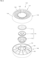
- FIG. 8 is a perspective view showing the discharge part and the rotation supporter in one embodiment
- FIG. 9 is an exploded perspective view showing a fan module in one embodiment
- FIG. 10 is a plan view showing the fan module in one embodiment
- FIG. 11 is a bottom view showing the fan module in one embodiment
- FIG. 12 is a cross-sectional view showing the fan module in one embodiment.
- the fan module 70 As illustrated in FIGS. 8 to 12 , the fan module 70, a circular mixed flow fan module, is applied, a shape of the fan module 70 may match or correspond to a cylinder shape of the inside of the first case 20. Accordingly, the first case 20 may not be scaled-up despite fixation or a coupling of the fan module 70, thereby enabling a compact product. Additionally, when the portable air purifier 1 according to the present disclosure is applied to a vehicle, the portable air purifier 1 may be small enough to fit into a cup holder.
- a fan type of the fan module 70 may be a mixed flow fan, and an inner structure of the fan module 70 may change to mount the mixed flow fan.
- a fan member 90 according to the disclosure may rotate as a result of an operation of a motor.
- a rotation shaft of the motor configured to rotate the fan member 90 may only connect to the fan member 90.
- a rotor may be installed in the fan member 90, and a stator may be installed in the fan housing 80 rotation of which is restricted. Since a magnetic field of the stator changes, the shaft connected to the fan member 90 may rotate along with the rotor such that the rotor and the fan member 90 rotate around the stator.
- the configuration of the motor for rotating the fan member 90 is well known. Thus, detailed description in relation to this is omitted.
- the fan module 70 in one embodiment may include a fan housing 80, a fan member 90, and a fan base 130.
- the fan housing 80 may be fixed to the inside of the first case 20, and may be modified in various ways within the technical scope in which the fan housing 80 is provided therein with an enough space for the fan member 90 to rotate.
- the fan housing 80 in one embodiment may include at least one of a support plate 81, a connecting and supporting part 82, a wire guide 83, a lateral surface supporter 84, an inner guide 85, and a protruding boss 86.
- the support plate 81 may be formed into a circular plate and provided with a hole at a center thereof.
- a motor may be disposed at the center of the support plate 81 or the shaft connected to the motor may be disposed in the first direction.
- the support plate 81 may be disposed on a lower side of a core member 310.
- the connecting and supporting part 82 may extend outside the support plate 81 and connect to the lateral surface supporter 84.
- a plurality of connecting and supporting parts 82 in one embodiment may be provided and formed into a rod.
- the connecting and supporting part 82, extending outside the support plate 81 in a radial direction of the support plate, may connect to the lateral surface supporter 84.
- the connecting and supporting part 82 in one embodiment may be disposed on a lower side of a core supporter 350 of the rotation supporter 300.
- Four connecting and supporting parts 82 may be disposed around the support plate 81 at 90-degree intervals, and the core supporter 350 may be disposed on an upper side of the connecting and supporting part 82 to face the connecting and supporting part 82.
- the wire guide 83 and the connecting and supporting part 82 may be disposed one after another, and the wire guide 83 may support a lower portion of an electric wire 600 of an electronic device such that the electric wire 600 moves along a lateral surface of the connecting and supporting part 82.
- the wire guide 83 may be formed into a projection that is disposed on a lower side of the lateral surface of the connecting and supporting part 82 and may guide an electric wire 600 of a motor installed in the support plate 81 in a way that the electric wire 600 is extended and disposed outside the fan housing 80.
- the wire guide 83 may form a concave groove which is disposed on the lateral surface of the connecting and supporting part 82 and in which the electric wire 600 is installed. Accordingly, the electric wire 600 installed in the wire guide 83 may be disposed in the concave groove on the lateral surface of the connecting and supporting part 82 and supported by the wire guide 83, thereby preventing the electric wire 600 from being damaged.
- the lateral surface supporter 84 may be formed into a cylindrical pipe and have upper and lower sides that are open. An outside of the lateral surface supporter 84 may contact an inside of the housing 10, and an inside of the lateral surface supporter 84 may connect to the connecting and supporting part 82.
- the inner guide 85 may form an inclined surface that is disposed downward at a slant from a lower side of the lateral surface supporter 84 toward the inside of the lateral surface supporter in a radial direction of the lateral surface supporter.
- the inner guide 85 may be formed inside the lateral surface supporter 84 and may prevent air, blown upward by the fan member 90, from moving to an entrance of the fan member 90 through an outer surface of the fan member 90, that is, prevent a whirl.
- the protruding boss 86 may extend to a lower end of the lateral surface supporter 84, and may be modified in various ways within the technical scope in which the protruding boss 86 is provided with a groove into which a coupling projection 134 of a fan base 130 described below is inserted.
- a plurality of protruding bosses 86 in one embodiment may be disposed in a circumferential direction of the lateral surface supporter 84.
- the fan member 90 may be disposed inside the fan housing 80 in a rotatable manner, and may be modified in various ways within the technical scope in which the fan member 90 moves air toward the discharge part 140.
- a mixed flow fan is used as the fan member 90 in one embodiment, but the fan member 90 is not limited. Another type of fan may be used as the fan member 90 according to the disclosure.
- the fan member 90 in one embodiment may include at least one of a hub 100, a fan wing 110 and a shroud 120.
- FIG. 13 is a perspective view showing a fan member in one embodiment
- FIG. 14 is a plan view showing the fan member in one embodiment
- FIG. 15 is a bottom view showing the fan member in one embodiment
- FIG. 16 is a front view showing the fan member in one embodiment
- FIG. 17 is a cross-sectional view showing the fan member in one embodiment.
- the hub 100 may be disposed at a center of the fan housing 80, and may be modified in various ways within the technical scope in which the hub 100 receives external power and rotates.
- the hub 100 may be disposed at a center of the fan member 90 in a radial direction of the fan member, and may rotate along with the rotor constituting the motor and the shaft that is an output shaft of the motor.
- the hub 100 in one embodiment may include at least one of a hub plate 101, a shaft coupler 102, an inner protrusion 105 and a skirt part 107.
- the hub plate 101 may be formed into a circular plate and be parallel with the support plate 81.
- the hub plate 101 may be provided with a shaft coupler 102.
- the shaft coupler 102 may be disposed at a center of the hub plate 101 in a radial direction of the hub plate.
- the shaft coupler 102 may protrude from an upper side and a lower side of the hub plate 101.
- the shaft coupler 102 may be coupled to an end of the shaft, configured to deliver rotation power, in an axial direction of the shaft.
- the shaft coupler 102 may be coupled to the shaft in a way that the shaft is fitted into the shaft coupler 102.
- a first reinforcing projection 103 may be disposed along an outer circumference of the shaft coupler 102 at predetermined intervals.
- the first reinforcing projection 103 may be radially disposed around the shaft coupler 102, and may form a strip-shaped projection outside the shaft coupler 102. Accordingly, stress concentrated on the shaft coupler 102 may be scattered through the first reinforcing projection 103, and structural rigidity of the shaft coupler 102 may improve.
- the inner protrusion 105 may protrude upward from the hub plate 101 to an upper portion in which the support plate 81 is installed.
- the inner protrusion 105 in one embodiment may be disposed along an outer edge of the hub plate 101 in a circular arc form.
- the inner protrusion 105 may be formed into a pipe extending in the up-down direction.
- a second reinforcing projection 106 may be disposed along an inner circumference of the inner protrusion 105 at predetermined intervals.
- the second reinforcing projection 106 may be disposed along an inner surface of the inner protrusion 105 in the first direction, and a lower side of the second reinforcing projection 106 may form a strip-shaped projection extending toward the shaft coupler 102. Accordingly, stress concentrated on the inner protrusion 105 may be scatted through the second reinforcing projection 106, and structural rigidity of the inner protrusion 105 may improve.
- the rotor of the motor may be fixed to an inside of the inner protrusion 105.
- the skirt part 107 may protrude upward from an edge of the hub plate 101 to the support plate 81.
- the skirt part 107 may form an inclined surface that is inclined outward in the second direction as the skirt part 107 becomes farther from the hub plate 101 in the first direction.
- the skirt part 107 may be disposed outside the inner protrusion 105, and an inner diameter of the skirt part 107 may increase gradually from a lower side to an upper side.
- a shape, in which the hub plate 101 and the skirt part 107 connect may be a truncated cone shape which is provided therein with a hollow hole and has one side open.
- the skirt part 107 may be formed into a funnel having an upper side open and a lower side blocked by the hub plate 101.
- the shroud 120 may be installed in a way that the shroud 120 connects to an end of the fan wing 110 in a ring shape, and may be modified in various ways within the technical scope in which the shroud 120 is spaced from the fan base 130.
- the shroud 120 may be arranged along an outer circumference of the skirt part 107, and the shroud 120 and the skirt part 107 may be connected by the fan wing 110. Additionally, an outer diameter of the hub 100 and an inner diameter of the shroud 120 may decrease gradually from an upper side to a lower side.
- the shroud 120 may be spaced a predetermined distance from the hub 100 in the radial direction and may be disposed outside the hub 100 in the radial direction of the hub.
- the shroud 120 may be spaced from the hub 100 by a distance corresponding to a length of the fan wing 110 in a radial direction of the fan wing.
- Each fan wing 110 may connect between the skirt part 107 included in the hub 100 and the shroud 120.
- the shroud 120 may form an inclined surface that is approximately parallel with the skirt part 107.
- the skirt part 107 and the shroud 120 are arranged in a way that a gap between the skirt part 107 and the shroud 120 increases gradually toward an upper side of the shroud 120, for example.
- An entrance projection 121 disposed on a lower side of the shroud 120 may be formed into a ring and may extend from the lower side of the shroud 120 having a funnel shape in the first direction. Since the entrance projection 121 is disposed inside a bell mouth 132 described below, air, flowing into an entrance on the lower side of the shroud 120 along an outer side of the shroud 120, may be prevented from whirling.
- a plurality of fan wings 110 may be provided and spaced along an outer circumferential surface of the hub 100 at regular intervals.
- the fan wing 110 may protrude outside the hub 100 with respect to the hub 100, and extend in a spiral form.
- the plurality of fan wings 110 may be spaced a predetermined distance apart from each other in a circumferential direction of the hub 100.
- the fan wing 110 in one embodiment may protrude outside the skirt part 107 in a centrifugal direction extending from a center of the shaft coupler 102 in a spiral shape. Under the assumption that a direction from the outside of the shaft coupler 102 toward the shat coupler 102 is a radial direction, an inside of the fan wing 110 in a radial direction of the fan wing may connect to the skirt part 107, and an outside of the fan wing 110 in the radial direction of the fan wing may connect to the shroud 120 described below.
- the skirt part 107 may be a portion directly connected to the fan wing 110 among the components of the hub 100 and directly contacting air passing through the fan wing 110.
- the skirt part 107 may closely relate to a path in which air passing through the fan module 70 flows.
- Each fan wing 110 connecting between the shroud 120 and the skirt part 107 may include a first end part 111, a second end part 112, a first edge 113 and a second edge 114.
- the first end part 111 may be disposed at a front end of the fan wing 110 in a rotation direction of the fan wing, and formed into a straight line that extends in the radial direction.
- the rotation direction is defined as a direction in which the fan member 90 rotates.
- the second end part 112 may be disposed at a rear end of the fan wing 110 in the rotation direction of the fan wing and formed radially around the shaft coupler 102.
- the first edge 113 may connect one end of the first end part 111 and one end of the second end part 112.
- the first edge 113 may connect to an inner circumferential surface of the shroud 120.
- the second edge 114 may connect the other end of the first end part 111 and the other end of the second end part 112.
- the second edge 114 may connect to the outer circumferential surface of the hub 100.
- one end of the first end part 111 and one end of the second end part 112 may connect to the inner circumferential surface of the shroud 120.
- the other end of the first end part 111 and the other end of the second end part 112 may connect to an outer circumferential surface of the skirt part 107.
- One end of the first end part 111 may be disposed closer to the center of the hub plate 101 in a radial direction of the hub plate than one end of the second end part 112, and the other end of the second end part 112 may be disposed closer to the center of the hub plate 101 in the radial direction of the hub plate than the other end of the first end part 111, since one end and the other end of the first end part 111 are disposed further forward than one end and the other end of the second end part 112 in the rotation direction and that a radius of the skirt part 107 decreases toward a front in the radial direction.
- the fan wing 110 may connect to the skirt part 107 of the hub 110.
- the skirt part 107 may form an inclined surface that is inclined upward, to guide a flow of air, flowing into the fan module 70, upward at a slant.
- the fan base 130 may be coupled to a lower side of the fan housing 80, and may be modified in various ways within the technical scope in which the fan base 130 guides air having passed through the filter part 40 into the fan member 90.
- the fan base 130 may be disposed between the filter part 40 and the fan member 90.
- An edge of the fan base 130 may have a shape corresponding to a shape of an edge of the filter part 40.
- the fan base 130 may have a ring shape with a hollow hole.
- a base plate 131 may be disposed between the filter part 40 and the fan member 90.
- the base plate 131 may be formed into a plate that extends in a ring shape and provided with a hollow hole for movement of air at a center thereof.
- a bell mouth 132 is installed in an annular shape on the inside of the base plate 131.
- the bell mouth 132 may have a longitudinal cross section that is concave and encircles a lower side of the entrance projection 121 of the shroud 120 and may extend in a circumferential direction.
- the bell mouth 132 may be formed in a way that the bell mouth 132 encircles an outer circumferential surface of the hollow hole formed at a center of the base plate 131.
- the bell mouth 132 may form a groove that is convex downward and concave upward.
- the bell mouth 132 may be at least partially inserted into the shroud 120 in a radial direction of the shroud.
- the bell mouth 132 may guide a suction flow at an entrance of the fan module 70 and contribute to improvement in suction and discharge performance of the fan module 70.
- a coupling projection 134 may protrude from the base plate 131 upward and be fitted-coupled to the groove of the protruding boss 86 of the fan housing 80 to fix the fan base 130 to the lower side of the fan housing 80.
- the fan base 130 and the fan housing 80 may be coupled at a plurality of positions.
- the fan member 90 may be installed between the fan base 130 and the fan housing 80 in a rotatable manner.
- a protruding rib 133 may protrude from the base plate 131 and be disposed outside the bell mouth 132 in a radial direction of the bell mouth.
- the protruding rib 133 in one embodiment may be disposed outside the bell mouth 132 in the radial direction of the bell mouth and installed in the form of a ring that encircles an outer circumference of the bell mouth 132.
- the protruding rib 133 and the base plate 131 may be integrally formed.
- the base plate 131, the bell mouth 132 and the protruding rib 133 may be integrally formed.
- the protruding rib 133 may be disposed at a slant at the same angle as that of an outer surface of the shroud 120, and a gap between the protruding rib 133 and the shroud 120 may remain constant.
- the protruding rib 133 may protrude in the form of an inclined surface.
- the inclined surface of the protruding rib 133 may be spaced a predetermined distance from the shroud 120 and be parallel with the inclined surface of the shroud 120.
- the inclined surface of the protruding rib 133 may have the same slant angle as the inclined surface of the inner guide 85 of the fan housing 80. Accordingly, part of air, moving upward through a space between the shroud 120 and the skirt part 107, may be prevented from moving to the entrance of the fan member 90 through the space between the shroud 120 and the protruding rib 133, that is, prevent a whirl.
- FIG. 18 is a perspective view showing a fan module 370 in another embodiment
- FIG. 19 is an exploded perspective view showing the fan module 370 in another embodiment.
- the fan module 370 may have a rectangular exterior. Additionally, since the fan module 370 is provided therein with a circular mixed flow fan module, a small-sized upward discharge-type air purifier, which ensures maximized hydrodynamic performance, may be provided.
- the fan module 370 in another embodiment may include a fan housing 380, a fan member 90 and a fan base 430.
- the fan housing 380 may have various exteriors within the technical scope in which the exterior of the fan housing 380 includes a rectangular edge.
- the fan housing 380 in one embodiment may include at least one of a support plate 381, a connecting and supporting part 382, a wire guide 383, a lateral surface supporter 384, an inner guide 385 and a protruding boss 386.
- the support plate 381 may be formed into a circular plate and provided with a hole at a center thereof.
- a motor may be disposed at the center of the support plate 381, or a shaft connected to the motor may be disposed in the first direction.
- the connecting and supporting part 382 may extend outside the support plate 381 and connect to the lateral surface supporter 384.
- a plurality of connecting and supporting parts 382 in one embodiment may be provided and formed into a rod.
- the connecting and supporting part 382, extending outside the support plate 381 in a radial direction of the support plate, may connect to the lateral surface supporter 384.
- the wire guide 383 and the connecting and supporting part 382 may be disposed one after another, and the wire guide 383 may support a lower portion of an electric wire 600 of an electronic device such that the electric wire 600 moves along a lateral surface of the connecting and supporting part 382.
- the wire guide 383 may be formed into a projection that is disposed on a lower side of the lateral surface of the connecting and supporting part 382 and may guide an electric wire 600 of a motor disposed on the support plate 381 in a way that the electric wire 600 is extended and disposed outside the fan housing 380.
- the wire guide 383 may form a concave groove which is disposed on the lateral surface of the connecting and supporting part 382 and in which the electric wire 600 is installed.
- the electric wire 600 installed in the wire guide 383 may be disposed in the concave groove on the lateral surface of the connecting and supporting part 382, and its lower portion may be supported by the wire guide 383, thereby preventing the electric wire 600 from being damaged.
- the lateral surface supporter 384 may be formed into a rectangular frame and have upper and lower sides that are open. An outside of the lateral surface supporter 384 may be formed into a rectangular frame, and an inside of the lateral surface supporter 384 may form a passage through which air moves and form an inner space having a rectangular or circular shape.
- the inner guide 385 may form an inclined surface that is disposed downward at a slant from a lower side of the lateral surface supporter 384 toward the inside of the lateral surface supporter in a radial direction of the lateral surface supporter.
- the inner guide 385 may be formed inside the lateral surface supporter 384 and may prevent air, blown upward by the fan member 90, from moving to an entrance of the fan member 90 through an outer surface of the fan member 90, that is, prevent a whirl.
- the protruding boss 386 may extend to a lower end of the lateral surface supporter 384, and may be modified in various ways within the technical scope in which the protruding boss 386 is provided with a groove into which a coupling projection 134 of a fan base 430 described hereunder is inserted.
- a plurality of protruding bosses 386 in one embodiment may be disposed at each edge of the lateral surface supporter 384.
- a mixed flow fan may be used as the fan member 90. Description in relation to this is provided above.
- a rectangular fan base 430 may be coupled to a lower side of a rectangular fan housing 380 and may be modified in various ways within the technical scope in which the fan base 430 guides air having passed though the filter part 40 into the fan member 90.
- a shape of the edge of the fan base 430 may correspond to a shape of the edge of the fan housing 380.
- the fan base 430 may be formed into a rectangular plate provided with a hollow hole.
- a base plate 431 may have a rectangular plate shape and be provided with a hollow hole for allowing air to move at a center thereof.
- a bell mouth 432 is installed in an annular shape on the base plate 431.
- the bell mouth 432 may have a longitudinal cross section that is concave and encircles a lower side of an entrance projection 121 of a shroud 120 and may extend in the circumferential direction.
- the bell mouth 432 may be formed in a way that the bell mouth 432 encircles an outer circumferential surface of the hollow hole formed at a center of the base plate 431.
- the bell mouth 432 may form a groove that is convex downward and concave upward.
- a coupling projection 434 may protrude from the base plate 431 upward and be fitted-coupled to the groove of the protruding boss 386 of the fan housing 380 to fix the fan base 430 to the lower side of the fan housing 380.
- the fan base 430 and the fan housing 380 may be coupled at a plurality of positions.
- the fan member 90 may be installed between the fan base 430 and the fan housing 380 in a rotatable manner.
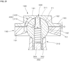
- FIG. 3 is a cross-sectional view showing a discharge part 140 in one embodiment connected to a rotation guide 400
- FIG. 4 is an exploded perspective view showing the discharge part 140 in one embodiment
- FIG. 5 is an exploded perspective view showing a rotation guide 300 in one embodiment
- FIG. 6 is an exploded cross-sectional view showing the discharge part 140 in one embodiment separated from a rotation supporter 300.
- the discharge part 140 may be disposed at an outlet 24 of a housing 10, may be installed in a rotation supporter 300 in a rotatable manner, and may be modified in various ways within the technical scope in which the discharge part 140 guides a discharge direction of air having passed through a fan module 70.
- the discharge part 140 according to the present disclosure may be installed in a sphere-shaped ball joint 360 included in the rotation supporter 300 in a rotatable manner and may smoothly rotate.
- the discharge part 140 disposed on an upper side of the housing 10 may be open in the up-down direction and connected to the rotation supporter 300 in a rotatable manner such that a discharge direction of air having passed through the fan module 70 is adjusted.
- the discharge part 140 in one embodiment may include a discharge body part 141, a first supporter 180 and a second supporter 190.
- the discharge body part 141 may be disposed at the outlet 24 of the housing 10 and may guide a discharge direction of air.
- the discharge body part 141 in one embodiment may include a first discharge part 150, a second discharge part 160 and a core mounting part 170.
- the first discharge part 150 may be disposed on one side (an upper side in FIG. 3 ) of the ball joint 360, and may be modified in various ways within the technical scope in which the first discharge part 150 is provided with a plurality of vanes 156 for guiding discharge of air.
- the first discharge part 150 in one embodiment may include a first discharge core 152, a first discharge body 154 and a vane 156.
- the first discharge core 152 may be disposed on an upper side of the ball joint 360 and may have various shapes including a circular plate shape.
- the first discharge body 154 may be spaced from the first discharge core 152 and disposed in a ring shape that encircles an outside of the first discharge core 152.
- An outside of the first discharge body 154 may be formed into a curved surface and installed in a state of being spaced from the housing 10. Accordingly, the first discharge body 154 may be prevented from contacting the hosing 10 when the first discharge part 150 rotates.
- first discharge core 152 and the first discharge body 154 are connected by the plurality of vanes 156, the first discharge core 152, the first discharge body 154 and the vane 156 may rotate together.
- the second discharge part 160 may be disposed on the other side (a lower side in FIG. 3 ) of the ball joint 360, may connect to the first discharge part 150 and may be modified in various ways within the technical scope in which the second discharge part 160 rotates around the ball joint 360 together with the first discharge part 150.
- the second discharge part 160 in one embodiment may include a second discharge core 161, a second discharge body 162 and a discharge core supporter 163.
- the second discharge core 161 may be coupled to the first discharge core 152 with the core mounting part 170 between the second discharge core 161 and the first discharge core 152.
- the second discharge core 161 may form a groove that is concave downward, and the first supporter 180 and the second supporter 190, which encircle the ball joint 360, may be disposed inside the second discharge core 161.
- the second discharge body 162 may be spaced from the second discharge core 161 and disposed in a ring shape that encircles an outside of the second discharge core 161.
- An outside of the second discharge body 162 may be formed into a curved surface and installed in a state of being spaced from the housing 10. Accordingly, the second discharge body 162 may be prevented from contacting the hosing 10 when the second discharge part 160 rotates.
- the second discharge core 161 and the second discharge body 162 are connected by the plurality of discharge core supporters 163, the second discharge core 161, the second discharge body 162 and the discharge core supporter 163 may rotate together.
- the core mounting part 170 may be disposed between the first discharge part 150 and the second discharge part 160, and may receive a manipulation signal through the first discharge part 150 or display an operation state of the portable air purifier 1 through the first discharge part 150.
- the core mounting part 170 in one embodiment may include a touch panel 171 disposed on a lower side of the first discharge core 152 and configured to receive a user's manipulation signal through the first discharge core 152, a display 172 disposed on a lower side of the touch panel 171, configured to provide image information toward the first discharge core 152 and including a PCB configured to receive the manipulation signal of the touch panel 171, and a fixing case 173 fixed to the first discharge part 150 while encircling the touch panel 171 and the display 172.
- the first supporter 180 may connect to the discharge body part 141 or the first supporter 180 and the discharge body part 141 may be integrally formed, and the first supporter 180 may be modified in various ways within the technical scope in which the first supporter 180 is provided with a first curved surface groove 182 formed into a concave groove.
- the first curved surface groove 182 may be installed in a way that the first curved surface groove 182 encircles the upper side of the ball joint 360 having a sphere shape.
- the first supporter 180 in one embodiment may include a first support body 181 and a first wing member 183.
- the first support body 181 may be disposed inside the first curved surface groove 182 formed into a concave groove and fixed to a center of the discharge body part 141.
- the first support body 181 in one embodiment may be coupled to a lower side of the second discharge part 160.
- the first support body 181 may be inserted into a lower side of the second discharge core 161 of the second discharge part 160 and fixed to an inside of the second discharge core 161.
- the first wing member 183 may include a first wing member 183 extending outside the first support body 181 and facing the second supporter 190.
- the first wing member 183 and the second supporter 190 may be fixed as a result of fastening of a fastening member 195 and may be coupled with a gap therebetween.
- the first wing member 183 may be formed into a plate that extends along a circular arc, and the first support body 181 may have a cylindrical shape that protrudes upward from a central portion of the first wing member 183, may be provided therein with the first curved surface groove 182 and may have a lower side that is open.
- the second supporter 190 may be coupled to the first supporter 180, and may be provided with a second curved surface groove 192 connected to the first curved surface groove 182 on an inner side thereof.
- the second curved surface groove 192 may be installed in a way that the second curved surface groove 192 encircles a lateral surface and part of a lower side of the ball joint 360 having a sphere shape.
- the second supporter 190 in one embodiment may be provided with a hollow hole part 193 that communicates in the up-down direction and may include a second support body 191 installed in the circumferential direction.
- the second curved surface groove 192 may be formed inside the second support body 191 facing the hollow hole part 193.
- An upper side of the discharge part 140 may be placed in the horizontal direction, and a position at which air having passed through the discharge part 140 is moved upward may be set to an initial position of the discharge part 140.
- an inner diameter of a lower end of the second curved surface grove 192 may be less than a maximum outer diameter of the ball joint 360.
- the second supporter 190 surrounding the lower side of the ball joint 360 is fixed to the first supporter 180 surrounding the upper side of the ball joint 360. Accordingly, it is possible to prevent the ball joint 360 from being separated to the outside of the second supporter 190.
- a frictional force between the first supporter 180 and the ball joint 360 is referred to as F1
- a frictional force between the second supporter 190 and the ball joint 360 is referred to as F2.
- F1 and F2 are inversely proportional to D.
- the frictional force between the first supporter 180 and the ball joint 360 and the frictional force between the second supporter 190 and the ball joint 360 may be inversely proportional to the distance between the first supporter 180 and the second supporter 190 that are installed to face each other with the ball joint 360 therebetween.
- D may decrease as a result of adjustment of a fastening state of the fastening member 195, and accordingly, F1 and F2 may increase. Additionally, when the discharge part 140 does not smoothly rotate due to the increase in F1 and F2, the fastening member 195 may be adjusted to increase D, and accordingly, F1 and F2 may decrease.
- the discharge part 140 When a direction of rotation of the discharge part 140 is adjusted manually, the discharge part 140 may rotate readily, and the discharge part 140 may be prevented from rocking after the completion of its rotation, thereby improving reliability in operation of the discharge part 140.
- the first supporter 180 may be provided with the first curved surface groove 182 that forms a groove concave downward
- the second supporter 190 may be provided with the second curved surface groove 192 that forms a groove concave along an inner circumference of the second support body 191 facing the hollow hole part 193.
- the upper side of the ball joint 360 may be inserted into the first curved surface groove 182, and the second curved surface groove 192 may be installed to encircle part of the lateral surface and part of a lower portion of the ball joint 360. Accordingly, the first supporter 180 and the second supporter 190 may rotate around the ball joint 360.
- the second supporter 190 may be fixed to the first supporter 180 by the fastening member 195, and the first supporter 180 may be fixed to the discharge body part 141.
- the discharge body part 141, the first supporter 180 and the second supporter 190 may form a single module and rotate around the ball joint 360.
- the sterilizer 200 may be disposed between the filter part 40 and the second case 30, and may be modified in various ways within the technical scope in which the sterilizer 200 emits a light ray for sterilization to the filter part 40.
- the sterilizer 200 in one embodiment may include at least one of a sterilizing and supporting part 210, a supporting part 220 and an emitter 230.
- the sterilizing and supporting part 210 may be disposed between the first case 20 and the second case 30 and may shield the lower portion of the first case 20.
- the sterilizing and supporting part 210 may be disposed on a lower side of the emitter 230, and may be modified in various ways within the technical scope in which the sterilizing and supporting part 210 connects to the housing 10 and movement of the sterilizing and supporting part 210 is restricted.
- Air introduced into the first case 20 through the entrance part 22 may be prevented from moving to the second case 30 by the sterilizing and supporting part 210. Accordingly, a flow rate of air moving to the fan module 70 may increase and air purification performance of the portable air purifier 1 may improve.
- the supporting part 220 may be modified in various ways within the technical scope in which the supporting part 220 protrudes from a center of the sterilizing and supporting part 210 upward and supports a lower portion of the emitter 230.
- the supporting part 220 may be disposed at a center of the entrance part 22 in a radial direction of the entrance part and a transverse cross section of the supporting part 220 may have a circular shape to reduce friction with air.
- the supporting part 220 may be formed into a pillar that protrudes from the center of the sterilizing and supporting part 210 upward.
- the supporting part 220 may be formed into a cylinder or a circular cone.
- the supporting part 220 in one embodiment may have a transverse cross section that is narrowed gradually from a lower side to an upper side and may be disposed at a center of the first case 20 provided with the entrance part 22, thereby minimizing friction with air.
- a transverse cross section of the sterilizing and supporting part 210 for sterilizing the filter part 40 may have a circular shape, and air suctioned through the entrance part 22 may rotate outside the supporting part 220 while rotating in a spiral shape thanks to an inclined shape of the entrance hole 23 and may move to the upper side on which the filter part 40 is disposed. That is, the sterilizer 200 may be disposed in a central portion of the first case 20 and air suctioned through the entrance part 22 may move upward while rotating around an outer circumference of the sterilizer 200, thereby reducing flow resistance of the sterilizer 200.
- the emitter 230 may be disposed on an upper side of the supporting part 220 and may emit a light ray for sterilization toward the filter part 140.
- the emitter 230 may be disposed on a perpendicular reference line that vertically passes through the center of the entrance part 22 in a radial direction of the entrance part.
- an entire surface area of a lower end of the filter part 40 may be sterilized by a relatively small number of sterilizing light sources 232, thereby reducing costs incurred for manufacturing, maintenance and repairs.
- the emitter 230 may be modified in various ways within the technical scope in which the emitter 230 is disposed at a position higher than or the same as a position of an upper end of the entrance part 22.
- the emitter 230 in one embodiment may include a printed circuit board 231 and a sterilizing light source 232.
- the printed circuit board 231 may be disposed on the upper side of the supporting part 220, and the sterilizing light source 232 for emitting a light ray for sterilization may be disposed on an upper side of the printed circuit board 231.
- the sterilizing light source 232 may be a UVC LED, and various types of sterilizing devices may be used within the technical scope in which the sterilizing light source 232 sterilizes germs in the filter part 40.
- the sterilizing light source 232 of the sterilizer 200 is disposed on an upper side of the entrance part 22, the sterilizing light source 232 may be prevented from emitting out of the first case 20 through the entrance part 22.
- FIG. 7 is a cross-sectional view showing a rotation supporter 300 in one embodiment
- FIG. 8 is a perspective view showing the discharge part 140 and the rotation supporter 300 in one embodiment
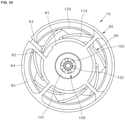
- FIG. 20 is a plan view showing a core supporter 350 in one embodiment.
- the rotation supporter 300 may connect to the housing 10 and support the discharge part 140 disposed at the outlet 24 of the housing 10 in a rotatable manner, and movement of the rotation supporter 300 may be restricted.
- One side of the rotation supporter may connect to the housing 10, and the other side may be disposed at a position facing the first curved surface groove 182 and the second curved surface groove 192.
- the rotation supporter may support the first supporter 180 and the second supporter 190 in a rotatable manner.
- the rotation supporter 300 in one embodiment may include a core member 310, a core supporter 350 and a ball join 360.
- the core member 310 may be disposed on a lower side of the discharge part 140 configured to adjust a discharge direction of air and may extend from a center of the outlet 24 to the discharge part 140.
- the core member 310 may be disposed on a lower side of the second supporter 190, may extend from the center of the outlet 24 to the second supporter 190 and may support the ball joint 360.
- the core member 310 may have an outside formed into a curved surface and a transverse cross section that is gradually reduced from a lower side connected to the core supporter 350 toward the ball joint 360, thereby minimizing resistance of air moving from the lower side to the upper side.
- the core member 310 may be formed into a circular cone shape and may have a transverse cross section that is gradually reduce toward the upper side.
- the core member 310 in one embodiment may include a core base 312, a core body 314 and a core connector 320.
- the core base 312 may form a lower portion of the core member 310 and may be fixed to the core supporter 350.
- the core base 312 may be disposed in a central portion of the housing 10 and formed into a pipe that extends in the up-down direction.
- the core body 314 may extend to an upper side of the core base 312 and may be formed into a circular cone having upper and lower sides that are open.
- the core connector 320 may be modified in various ways within the technical scope in which the core connector 320 forms a space for installing a position informing part 500 and a space for connecting the ball joint 360 inside the core body 314.
- the core connector 320 in one embodiment may include a joint seating part 330 and an inner fastening and supporting part 340.
- the joint seating part 330 may form a space for coupling the core body 314 and the ball joint 360 through an upper side of the core body 314.
- the joint seating part 314 in one embodiment may include a curved surface supporter 332 forming a surface that is concavely curved to allow an outside of the ball joint 360 to be seated on the upper side of the core body 314 facing the ball joint 360, and a joint connecting hole 334 forming a hole for allowing the ball joint 360 to be disposed at an upper end of the core body 314.
- the inner fastening and supporting part 340 may extend to an inside of the core body 314, and may be modified in various ways within the technical scope in which the inner fastening and supporting part 340 supports the ball joint 360 and a first adjusting bolt 520 of the position informing part 500.
- the inner fastening and supporting part 340 in one embodiment may includes a first fastening and supporting part 342 that extends to the inside of the core body 314 and forms a hole through which a body of the first adjusting bolt 520 passes, and a second fastening and supporting part 344 that is disposed on an upper side of the first fastening and supporting part 342 and encircles an outside of a mounting projection 369 extending to the lower side of the ball joint 360.
- the core supporter 350 may extend outside the core member 310 and may be fixed to the inside of the housing 10, and may be modified in various ways within the technical scope in which movement of the core supporter 350 is restricted together with movement of the core member 310.
- the core supporter 350 in one embodiment may include a first core supporter 352, a second core supporter 354 and a connecting part 356.
- the first core supporter 352 may be coupled to the lower portion of the core member 310 and may be installed in a ring shape.
- the core base 312 may be coupled to an inside of the first core supporter 352, and the second core supporter 354 having a ring shape is installed outside the first core supporter 354. Movement of the second core supporter 354 may be restricted using various fixing methods such as a method by which the second core supporter 354 is fixed to the housing 10 based on fitting or using a bolt and the like.
- the first core supporter 352 and the second core supporter 354 may be connected by the connecting part 356.
- the connecting part 356 may be installed spirally or radially with respect to the first core supporter 352. Since the first core supporter 352 in one embodiment is installed spirally along a direction of winds discharged from the fan module 70, frictional resistance between the connecting part 356 and air may decrease.
- the ball joint 360 may be coupled to the core member 310, and may be modified in various ways within the technical scope in which the ball joint 360 supports the discharge part 140 in a rotatable manner.
- a lower side of the ball joint 360 may be coupled to the core member 310, and movement of the ball joint 360 may be restricted.
- An upper side of the ball joint 360 may be inserted into the discharge part 140 and may support the discharge part 140 in a rotatable manner.
- the upper side of the ball joint 360 in one embodiment may be disposed inside the first curved surface groove 182 and the second curved surface groove 192 and may support the first supporter 180 and the second supporter 190 in a rotatable manner.
- the ball joint 360 may be formed into a sphere disposed inside a sphere-shaped groove formed by the first curved surface groove 182 and the second curved surface groove 192.
- An outer diameter of the ball joint 360 may be greater than the inner diameter of the lower end of the second curved surface groove 192. Accordingly, the ball joint 360 may be prevented from escaping out of the second supporter 190.
- An end of the ball joint 360 may have a sphere shape, may be disposed inside the discharge part 140 and may support the discharge part 140 in a rotatable manner.
- the upper side of the ball joint 360 may have a sphere shape, and a mounting projection 369 formed into a bar extending from the sphere-shaped upper side to the lower side may be inserted into and fixed to the core member 310 through a joint connecting hole 334 disposed on an upper side of the core member 310.
- the ball joint 360 and the core member 310 may be fixed using various fixing methods such as a screw coupling, a pin coupling or using an adhesive and the like.
- the ball joint 360 in one embodiment may include a joint body 362 and a mounting projection 369.
- the joint body 362 may be formed into a sphere and may be provided therein with a first mounting hole 363 and a second mounting hole 364.
- the first mounting hole 363 may form a groove for fastening the guide projection 410 of the rotation guide 400 outside the joint body 362.
- the second mounting hole 364 spaced from the first mounting hole 363 may forma hole that passes through the joint body 362 in the up-down direction.
- the second mounting hole 364 may be disposed at a center of the joint body 362 and may form a hole for installing an informing projection 510 of the position informing part 500.
- the second mounting hole 364 in one embodiment may include a small diameter hole 368 that forms a hole extending from an upper end of the ball joint 360 to an inside of the ball joint 360, and a large diameter hole 366 that communicates with a lower side of the small diameter hole 368 and forms a hole downward.
- An inner diameter of the large diameter hole 366 may be greater than an inner diameter of the small diameter hole 368.
- a moving head 512 of a moving projection 511 of the position informing part 500 may be disposed inside the large diameter hole 366, and the moving head 512 of the moving projection 511 my protrude from the ball joint 360 upward through the small diameter hole 368.
- the mounting projection 369 may be formed into a pipe that extends to a lower side of the joint body 362 and may be provided therein with an inner elastic member 530 of the position informing part 500.
- the mounting projection 369 may be inserted into the core member 310 through the joint connecting hole 334 and disposed inside the second fastening and supporting part 344.
- the mounting projection 369 may be disposed inside the second fastening and supporting part 344 simply in a state of being inserted into the second fastening and supporting part, and since the mounting projection 369 is provided therein with a screw thread, the first adjusting bolt 520 may be fastened to an inside of the mounting projection 369.
- an outside of the mounting projection 369 and an inside of the second fastening and supporting part 344 may have a screw thread such that the mounting projection 369 is fastened to the second fastening and supporting part 344.
- the rotation guide 400 may be respectively installed in the discharge part 140 and the rotation supporter 300, and may be modified in various ways within the technical scope in which the rotation guide 400 guides rotation of the discharge part 140 such that the discharge part 140 rotates at predetermined angles.
- the rotation guide 400 in one embodiment may include a guide projection 410 and a guide groove 420.
- the guide projection 410 may connect to the ball joint 360 or the guide projection 410 and the ball joint 360 may be integrally formed.
- the guide projection 410 may be formed into a projection that protrudes outside the ball joint 360.
- the guide projection 410 in one embodiment may be formed into a bolt and may include a held head 411 held outside the ball joint 360 and a fastened body 412 extending from the held head 411 and fastened to the inside of the ball joint 360.
- the fastened body 412 may be fastened to the first mounting hole 363.
- the guide groove 420 may be modified in various ways within the technical scope in which the guide groove 420 is provided with a concave groove inside the discharge part 140 facing the guide projection 410.
- the guide groove 420 in one embodiment may be installed in at least one of the first supporter 180 and the second supporter 190 facing the ball joint 360. Alternatively, the guide groove 420 may be formed respectively in the first supporter 180 and the second supporter 190.
- a first groove 421 may be formed inside the first supporter 180 disposed on a path in which the guide projection 410 moves, and a second groove 422 may be formed inside the second supporter 190.
- an angle between one end and the other end of the guide groove 420 may be 30 degrees with respect to the center of the joint body 362. If the rotation angle of the discharge part 140 changes, the angle between one end and the other end of the guide groove 420 may also change with respect to the center of the joint body 362. Accordingly, the guide projection 410 may be inserted into the guide groove 420 and may be held in the guide groove 420 such that rotation of the discharge part 140 at the predetermined rotation angle or greater is restricted.
- the position informing part 500 may be modified in various ways within the technical scope in which the position informing part 500 is held in the discharge part 140 and provides a sense of manipulation when the discharge part 140 is at a predetermined position.
- the predetermined position of the discharge part 140 may be set to an initial position where air having passed through the discharge part 140 is discharged upward, but not limited.
- the predetermined position of the discharge part 140 may be set to various rotation positions of the discharge part 140.
- the position informing part 500 in one embodiment may include an informing projection 510 and an informing groove 540.
- the informing projection 510 may be provided with a moving projection 511 that is pressed by an elastic force toward the outside of the ball joint 360, and may be modified in various ways within the technical scope in which the moving projection 511 protrudes outside the ball joint 360 when the discharge part 140 is at the predetermined position.
- the informing projection 510 in one embodiment may include a moving projection 511, a first adjusting bolt 520 and an inner elastic member 530.
- the moving projection 511 may move along the second mounting hole 364 of the joint body 362 in the up-down direction.
- the moving projection 511 in one embodiment may be formed into a bolt and may include a moving head 512 and a moving body 514.
- the moving head 512 may be disposed inside the large diameter hole 366, and an upward movement of the moving head 512 may be restricted since the moving head is held by a step disposed between the large diameter hole 366 and the small diameter hole 368.
- a convexly curved surface may be formed at an upper end of the moving body 514 that extends from the moving head 512 upward.
- the first adjusting bolt 520 may be fastened to the first fastening and supporting part 342 of the core member 310.
- the first adjusting bolt 520 may be fastened to the large diameter hole 366 disposed inside the joint body 362.
- the first adjusting bolt 520 may not be fastened to an inside of the first fastening and supporting part 342 while being fastened to the screw thread included inside the large diameter hole 366.
- a lower side of the inner elastic member 530 may be supported by the first adjusting bolt 520 and an upper side may support the moving projection 511.
- a coil spring may be used as the inner elastic member 530 in one embodiment, and the moving projection 511 may be pressed by elasticity.
- the informing groove 540 may be modified in various ways within the technical scope in which the informing groove forms a groove into which the moving projection 511 is inserted and held, in the discharge part 140 facing the informing projection 510.
- the informing groove 540 in one embodiment may be formed in the first supporter 180.
- the informing groove 540 having a concave shape may be formed on a lower side of the first support body 181, and when the discharge part 140 is at the initial position, the informing groove 540 may be at a position facing the moving projection 511. Accordingly, the moving projection 511 may be inserted into the informing groove 540 and may provide a sense of manipulation to a user.
- the entrance part 22 for suctioning external air may be disposed along the outer circumference of the first case 20. Accordingly, external air outside the first case 20 may move into the first case 20 through the entrance part 22 and a flow rate of suctioned air may increase.
- air outside the portable air purifier 1 may be suctioned into the portable air purifier 1.
- the air outside the portable air purifier 1 may form an air flow rotating along an outer circumference of the sterilizing and supporting part 210 in a spiral shape while passing through the entrance hole 23 inclined.
- the air which is suctioned into the first case 20 and moves upward while rotating in a spiral shape, may pass through the filter part 40, and in this process, physical particles such as dust/fine dust/ultra fine dust and the like, chemical substances such as odorant particles/harmful gases and the like and microorganisms such as germs/viruses and the like, which are included in the air, may be filtered.
- filter part 40 and the fan module 70 are disposed on the same straight line in the up-down direction, flow loss may be minimized and air may be suctioned and filtered effectively.
- the air having passed through the filter part 40 i.e., the purified air, may be introduced into the fan module 70.
- a flow of the air may be guided by the bell mouth 132, and accordingly, the air may be introduced into the fan module 70 effectively and smoothly.
- the air introduced into the fan module 70 may be discharged from an upper side of the fan module 70.
- the air discharged from the upper side of the fan module 70 may be discharged in a mixed flow direction.
- the mixed flow direction may be defined as an upward diagonal direction.
- the air introduced into a central portion on a lower side of the fan module 70 may move upward through a discharge opening that is provided along an inside of an edge of the fan module 70 in a ring shape. That is, the air introduced into a lower portion of the fan module 70 may be discharged in the upward diagonal direction such that a passage for movement of air and a direction of a flow path of air of the rotation supporter 300 are matched, since a mixed flow fan is applied to the fan module 70, thereby reducing flow loss.
- the air discharged from the upper side of the fan module 70 i.e., the purified air, may be introduced into the discharge part 140 from the lower side thereof and may be discharged from the upper side of the discharge part 140.
- the discharge part 140 may rotate within a range of predetermined angles. Accordingly, a direction of the discharged air may be adjusted depending on an angle at which the discharge part 140 is installed.
- an inside of the discharge part 140 may form a concave groove. Accordingly, an increase in the discharge resistance of air, a direction of which is changed by the discharge part 140, may be suppressed. Further, since the filter part 140, the fan module 70 and the discharge part 140 are disposed on the same straight line in the up-down direction, flow loss of air may be minimized, air may be suctioned effectively, and filtered and purified air may be discharged effectively.
- the discharge part 140 may rotate around the ball joint 360.
- the discharge part 140 may be rotatably installed in the ball joint 360 included in the rotation supporter 300.
- the discharge part 140 may be installed in a way that the discharge part 140 rotates around the ball joint 360 such that a discharge direction of air is readily adjusted.
- the upper side of the discharge part 140 needs to be installed in the horizontal direction, and the informing groove 540 formed in the first supporter 180 of the discharge part 140 may face the informing projection 510. Accordingly, the moving projection 511 pressed by the inner elastic member 530 may be held in the informing groove 540, and the user may readily ascertain that the discharge part 140 is placed at the right position that is an initial position.
- the core mounting part 170 serving as a touch panel may be installed in a central portion of the discharge part 140, and an electric wire 600 connected to the core mounting part 170 may connect to a lower side of the housing 10. Accordingly, when a panel makes a 360 degree rotation without additional restrictions on the rotation of the panel, the electric wire may be broken or damaged. To prevent this from happening, the rotation guide 400 may be installed to adjust the rotation angle of the discharge part 140 within predetermined angles, thereby preventing damage to the electric wire 600.
- the discharge part 140 may rotate within the predetermined angles, thereby preventing the electric wire 600 connected to the discharge part 140 from being broken or damaged, since the guide projection 410 protruding outside the ball joint 360 is held in the guide groove 420 formed inside the discharge part 140.
- the guide projection 410 protruding outside the ball joint 360 may bump against the first supporter 180 and the second supporter 190 disposed at a boundary of the guide groove 420.
- the discharge part 140 may rotate with the predetermined angles.
Landscapes
- Chemical & Material Sciences (AREA)
- Engineering & Computer Science (AREA)
- Chemical Kinetics & Catalysis (AREA)
- Combustion & Propulsion (AREA)
- Mechanical Engineering (AREA)
- General Engineering & Computer Science (AREA)
- Disinfection, Sterilisation Or Deodorisation Of Air (AREA)
- Structures Of Non-Positive Displacement Pumps (AREA)
- Filtering Of Dispersed Particles In Gases (AREA)
Abstract
Description
- Disclosed herein is a portable air purifier, and specifically, a portable air purifier in which a discharge part for discharging air upward can be installed in a rotatable manner.
- Air purifiers are devices that are widely used in our daily lives. The devices can filter physical particles such as dust, fine dust, ultra fine dust and the like, chemical substances such as odorant particles, harmful gases and the like, and microorganisms such as germs, viruses and the like, to purify air.
- People cannot live without air purifiers in an industrial society since more and more people are greatly affected by fine dust and suffer from allergies. Accordingly, there is a growing demand for the devices.
- Ordinarily, a large-sixed air purifier is used in a house that is 100 square meters or greater. The air purifier can be provided with a filter for physical particles such as dust and the like, a filter for chemical substances such as gas and the like, and a filter for microorganisms such as germs, viruses and the like. That is, such a large-sized air purifier capable of accommodating various types of filters can be used in a large space.
- However, the large-sized air purifier is rarely used in a small space such as a studio apartment, a space in a vehicle and the like considering space availability, mobility and energy efficiency. Additionally, a user who moves from place to place usually uses a small-sized air purifier. Under the circumstances, there is a growing need for a portable air purifier that is easy to carry.
- The portable air purifiers need to be small and lightweight enough for users to carry such that the users can easily carry and use the portable air purifiers anywhere. That is, the portable air purifiers are useful for people who often go out and move from place to place instead of staying in a place such as a house.
- In a prior art document (
KR Patent Publication No. 10-2020-0037187 - A portable air purifier has a limited size such that a user carries the portable air purifier readily. Accordingly, the portable air purifier is not provided with an additional discharge part that can rotate to adjust a discharge direction of air.
- A background art in relation to the subject matter of the present disclosure is disclosed in
KR Patent Publication No. 10-2020-0037187 - The present disclosure is directed to a portable air purifier in which a discharge part for guiding discharge of air is installed in a rotatable manner.
- The present disclosure is also directed to a portable air purifier in which a discharge part rotates within predetermined angles, thereby preventing damage to an electric wire connected to the discharge part.
- Aspects according to the present disclosure are not limited to the above ones, and other aspects and advantages that are not mentioned above can be clearly understood from the following description and can be more clearly understood from the embodiments set forth herein. Additionally, the aspects and advantages in the present disclosure can be realized via means and combinations thereof that are described in the appended claims.
- In a portable air purifier according to the present disclosure, a discharge part may be installed on an upper side of a housing in a way that the discharge part is supported by a rotation supporter in a rotatable manner.
- Specifically, the discharge part may be disposed at a ball joint included in the rotation supporter and may rotate around the ball joint, thereby readily adjusting a discharge direction of air.
- In the portable air purifier according to the present disclosure, a rotation angle of the discharge part may be limited within the predetermined angles by a rotation guide.
- Specifically, a guide projection protruding outside the ball joint may be held in a guide groove formed inside the discharge part, and the discharge may rotate within the predetermined angles, thereby preventing an electric wire connected to the discharge part from being broken or damaged.
- A portable air purifier in one embodiment may include a housing provided with an entrance part configured to suction air, provided therein with a filter part and a fan module and forming an air flow path in an up-down direction, a discharge part disposed at an outlet of the housing and configured to guide a discharge direction of air, a rotation supporter which is connected to the housing, movement of which is restricted and which supports the discharge part in a rotatable manner, and a rotation guide disposed respectively at the discharge part and the rotation supporter and configured to guide rotation of the discharge part to allow the discharge part to rotate within predetermined angles.
- The rotation supporter may include a core member disposed on a lower side of the discharge part and extended from a center of the outlet to the discharge part, a core supporter which is extended outside the core member, which is fixed to an inside of the housing and movement of which is restricted together with movement of the core member, and a ball joint a lower side of which is coupled to the core member and movement of which is restricted, and an upper side of which is inserted into the discharge part and supports the discharge part in a rotatable manner.
- The core member may have an outside that is a curved surface and have a transverse cross section that is gradually reduced from a lower side connected to the core supporter toward the ball joint.
- The core member may have a circular cone shape and have a transverse cross section that is gradually reduced further toward an upper side.
- The rotation guide may include a guide projection connected to the ball joint or integrated with the ball joint and protruding outside the ball joint, and a guide groove forming a concave groove inside the discharge part facing the guide projection.
- The guide projection may be inserted into the guide groove, and a rotation of the discharge part at a predetermined angle or greater may be restricted since the guide projection is held inside the guide groove.
- The discharge part may include a discharge body part disposed at the outlet of the housing and configured to guide a discharge direction of air, a first supporter connected to the discharge body part or integrated with the discharge body part and provided with a first curved surface groove formed into a concave groove, and a second supporter coupled to the first supporter and provided therein with a second curved surface groove connected to the first curved surface groove.
- The ball joint may be disposed in an inner space formed by the first curved surface groove and the second curved surface groove, and may support the first supporter and the second supporter in a rotatable manner.
- The guide groove may be disposed at at least one of the first supporter and the second supporter facing the ball joint.
- The portable air purifier may further include a position informing part held in the discharge part and providing a sense of manipulation when the discharge part is at a predetermined position.
- The position informing part may include an informing projection provided with a moving projection that is pressed against an outside of the ball joint by an elastic force, wherein when the discharge part is at a predetermined position, the moving projection protrudes outside the ball joint, and an informing groove forming a groove into which the moving part is inserted and held, inside the discharge part facing the informing projection.
- The informing projection may include a first adjusting bolt fastened to a lower side of a mounting hole disposed at the ball joint, and an inner elastic member a lower side of which is supported by the first adjusting bolt, an upper side of which supports the moving projection and which presses the moving projection using an elastic force.
- A portable air purifier according to the present disclosure a housing provided with an entrance part configured to suction air, provided therein with a filter part and a fan module and forming an air flow path in an up-down direction, a discharge body part disposed at an outlet of the housing and configured to guide a discharge direction of air, a first supporter connected to the discharge body part or integrated with the discharge body part and provided with a first curved surface groove formed into a concave grove, a second supporter coupled to the first supporter and provided therein with a second curved surface groove connected to the first curved surface groove, and a rotation supporter one side of which connects to the housing, the other side of which is disposed at a position facing the first curved surface groove and the second curved surface groove and which supports the first supporter and the second supporter in a rotatable manner.
- The rotation supporter may include a core member disposed on a lower side of the second supporter and extended from a center to the outlet to the second supporter, a core supporter which is extended outside the core member, which is fixed to an inside of the housing and movement of which is restricted together with movement of the core member, and a ball joint, a lower side of which is coupled to the core member and movement of which is restricted and an upper side of which is disposed inside the first curved surface groove and the second curved surface groove, and which supports the first supporter and the second supporter in a rotatable manner.
- The first supporter may include a first support body provided therein with the first curved surface groove formed into a concave groove and fixed to a center of the discharge body part, and a first wing member extending outside the first support body and facing the second supporter.
- The first wing member and the second supporter may be fixed as a result of fastening of a fastening member.
- The second supporter may include a second support body provided with a hollow hole part communicating in the up-down direction and installed in a circumferential direction.
- The second support body facing the hollow hole part may be provided therein with the second curved surface groove.
- The rotating supporter may include a sphere-shaped ball joint formed disposed inside a sphere-shaped groove formed by the first curved surface groove and the second curved surface groove.
- An outer diameter of the ball joint may be greater than an inner diameter of a lower end of the second curved surface groove to prevent the ball joint from escaping out of the second supporter.
- A frictional force between the first supporter and the ball joint and a frictional force between the second supporter and the ball joint may be inversely proportional to a distance between fie first supporter and the second supporter that are arranged to face each other with the ball joint therebetween.
- In a portable air purifier according to the present disclosure, a discharge part may be installed on an upper side of a housing in a way that the discharge part is supported by a rotation supporter in a rotatable manner to readily adjust a discharge direction of air, thereby ensuring improvement in user satisfaction.
- In the portable air purifier, a rotation angle of the discharge part may be limited to predetermined angles by a rotation guide, and an electric wire connected to the discharge part may be prevented from being broken or damaged, thereby ensuring a reduction in costs incurred for maintenance and repairs.
- In the portable air purifier, a moving projection protruding outside a ball joint may be held in an informing groove formed at the discharge part, and a user may readily ascertain the ball joint arrives at an initial position, thereby ensuring improvement in user convenience.
- Specific effects are described along with the above-described effects in the section of Detailed Description.
- The accompanying drawings constitute a part of the specification, illustrate one or more embodiments in the disclosure, and together with the specification, explain the disclosure, wherein:
-
FIG. 1 is a perspective view showing a portable air purifier in one embodiment; -
FIG. 2 is a cross-sectional view showing the portable air purifier in one embodiment; -
FIG. 3 is a cross-sectional view showing a discharge part in one embodiment connected to a rotation guide; -
FIG. 4 is an exploded perspective view showing the discharge part in one embodiment; -
FIG. 5 is an exploded perspective view showing a rotation guide in one embodiment; -
FIG. 6 is an exploded cross-sectional view showing the discharge part in one embodiment separated from a rotation supporter; -
FIG. 7 is a cross-sectional view showing a rotation supporter in one embodiment; -
FIG. 8 is a perspective view showing the discharge part and the rotation supporter in one embodiment; -
FIG. 9 is an exploded perspective view showing a fan module in one embodiment; -
FIG. 10 is a plan view showing the fan module in one embodiment; -
FIG. 11 is a bottom view showing the fan module in one embodiment; -
FIG. 12 is a cross-sectional view showing the fan module in one embodiment; -
FIG. 13 is a perspective view showing a fan member in one embodiment; -
FIG. 14 is a plan view showing the fan member in one embodiment; -
FIG. 15 is a bottom view showing the fan member in one embodiment; -
FIG. 16 is a front view showing the fan member in one embodiment; -
FIG. 17 is a cross-sectional view showing the fan member in one embodiment; -
FIG. 18 is a perspective view showing a fan module in another embodiment; -
FIG. 19 is an exploded perspective view showing the fan module in another embodiment; -
FIG. 20 is a plan view showing a core supporter in one embodiment; and -
FIG. 21 is a view showing a ball joint installed between a first supporter and a second supporter in one embodiment. - The above-described aspects, features and advantages are specifically described hereunder with reference to the accompanying drawings such that one having ordinary skill in the art to which the present disclosure pertains can easily implement the technical spirit of the disclosure. In the disclosure, detailed description of known technologies in relation to the subject matter of the disclosure is omitted if it is deemed to make the gist of the disclosure unnecessarily vague. Below, preferred embodiments according to the disclosure are specifically described with reference to the accompanying drawings. In the drawings, identical reference numerals can denote identical or similar components.
- The terms "first", "second" and the like are used herein only to distinguish one component from another component. Thus, the components should not be limited by the terms. Certainly, a first component can be a second component unless stated to the contrary.
- When one component is described as being "in an upper portion (or a lower portion)" of another component, or "on (or under)" another component, one component can be placed on the upper surface (or under the lower surface) of another component, and an additional component may be interposed between another component and one component on (or under) another component.
- When one component is described as being "connected", "coupled", or "connected" to another component, one component can be directly connected, coupled or connected to another component. However, it is also to be understood that an additional component can be "interposed" between the two components, or the two components can be "connected", "coupled", or "connected" through an additional component.
- Throughout the disclosure, each component can be provided as a single one or a plurality of ones, unless explicitly stated to the contrary.
- The singular forms "a", "an" and "the" are intended to include the plural forms as well, unless explicitly indicated otherwise. It should be further understood that the terms "comprise" or "have" and the like, set forth herein, are not interpreted as necessarily including all the stated components or steps but can be interpreted as excluding some of the stated components or steps or can be interpreted as including additional components or steps.
- Throughout the disclosure, the terms "A and/or B" as used herein can denote A, B or A and B, and the terms "C to D" can denote C or greater and D or less, unless stated to the contrary.
-
FIG. 1 is a perspective view showing a portable air purifier 1 in one embodiment, andFIG. 2 is a cross-sectional view showing the portable air purifier 1 in one embodiment. - As illustrated in
FIGS. 1 and2 , the portable air purifier 1 in the embodiment may have an approximate cylinder shape. The portable air purifier 1 may include ahousing 10, afilter part 40, afan module 70, adischarge part 140, asterilizer 200, arotation supporter 300, and at least one of arotation guide 400 and aposition informing part 500. - The
housing 10 may be provided with anentrance part 22, and thefilter part 40, thesterilizer 200 and thefan module 70 may be disposed inside thehousing 10. Thehousing 10 may form an air flow path in an up-down direction. Since a cylindrical air flow path is formed inside thehousing 10, frictional resistance of air moving in the up-down direction may decrease. - Additionally, centers of the
entrance part 22, thefilter part 40, thesterilizer 200, thefan module 70, theoutlet 24 and therotation supporter 300 may be aligned in the up-down direction along a perpendicular reference line that passes through a center of thehousing 10 in the up-down direction. Accordingly, the length of a path, in which air moves, may decrease, flow resistance of air may be reduced, and efficiency of air purification may improve, since air moving from a lower side to an upper side of thehousing 10 flows linearly in a perpendicular direction. - When the portable air purifier 1 is disposed on a horizontal surface, the perpendicular reference line may align with a perpendicular line. The
housing 10 may be made of a single member. However, thehousing 10 may be made of a plurality of members, for example. - The portable air purifier 1 may be formed into a cylinder that is entirely long and stands in the up-down direction. Thus, a user may use the portable air purifier 1 in a state in which the portable air purifier 1 stands or lies. Additionally, since the portable air purifier 1 can be used in a state in which the portable air purifier 1 is seated in a groove such as a cup holder being concave downward, the portable air purifier 1 may stay at the same position reliably in places, e.g., inside a vehicle that rocks.
- Directions are defined as follows. Under the assumption that a portion, where the
discharge part 140 is disposed with respect to thefirst case 20, is referred to as an upper portion and that a portion, where thesecond case 30 is disposed with respect to thefirst case 20, is referred to as a lower portion, a "first direction" denotes an up-down direction or an axial direction. The first direction may have the same meaning as the perpendicular direction. A "second direction" is perpendicular to the first direction and denotes a left-right direction, a horizontal direction or a radial direction. - The portable air purifier 1 in this embodiment may include a
housing 10, afilter part 40, afan module 70, adischarge part 140, arotation supporter 300, arotation guide 400. The portable air purifier 1 may further include aposition informing part 500, asterilizer 200 and abattery 240. - The
housing 10 may include afirst case 20 and asecond case 30. Thefirst case 20 and thesecond case 30 may form an exterior skeleton of the portable air purifier 1. Lateral and bottom surfaces of the portable air purifier 1 may be formed by thefirst case 20 and thesecond case 30. An accommodation space 21 may be formed in thefirst case 20 and thesecond case 30. Electronic components and the like including thefilter part 40, thefan module 70, thesterilizer 200, therotation supporter 300 and thebattery 240 may be accommodated in the accommodation space 21. Thefirst case 20 and thesecond case 30 have enough strength to protect the accommodated components from an external impact, for example. - The
filter part 40 may be installed in the accommodation space 21 of thefirst case 20 and disposed between thefan module 70 and anentrance part 22. That is, thefilter part 40 may be disposed below thefan module 70, and may purify air suctioned through theentrance part 22 of the portable air purifier 1. The air, which is purified while passing through thefilter part 40, may be discharged from an upper portion of the portable air purifier 1, passing through thefan module 70 and thedischarge part 140. - The
filter part 40 may be installed inside thefirst case 20, and may purify air suctioned into theentrance part 22. Thefilter part 40 may be formed into a cylinder that extends in the up-down direction. - The
filter part 40 may include a single filter or when necessary, a plurality of filters stacked. Thefilter part 40 may be further provided with a filter case (not illustrated) for fixing a filter. - The filter case may be fixed to an inside of the
first case 20 and have an insertion space for accommodating a filter inside the filter case. - The
fan module 70 may be accommodated in the accommodation space 21 in thefirst case 20 and disposed between thedischarge part 140 and thefilter part 40. Specifically, thefan module 70 may be disposed between anoutlet 24 and thefilter part 40. That is, thefan module 70 may be disposed over thefilter part 40, and theoutlet 24, therotation supporter 300, therotation guide 400 and thedischarge part 140 may be disposed over thefan module 70. Thefan module 70 may suction air, introduced into a lower portion of thefilter part 40 through theentrance part 22, and discharge the air to an upper portion of thefirst case 20. - The center of rotation of the
discharge part 140 may be aligned with a center of thefan module 70 in the up-down direction. Air suctioned through theentrance part 22 may move upward, and be discharged from an upper side of the portable air purifier 1 while passing through thefilter part 40, thefan module 70 and thedischarge part 140 one after another. - In this embodiment, the
fan module 70 includes a mixed flow fan, for example. Thefan module 70 may suction air having passed through thefilter part 40 in the axial direction and discharge the air in a direction between the axial direction and the radial direction. - The
discharge part 140 may be disposed on an upper side of thefirst case 20 in a rotatable manner, and may guide a direction of discharge of air moved upward through theoutlet 24. Therotation supporter 300 may be disposed over thefirst case 20, and thedischarge part 140 may be installed in therotation supporter 300 in a rotatable manner. Both of the upper and lower sides of thedischarge part 140 may be open. Accordingly, air, moved to a lower portion of thedischarge part 140 through theoutlet 24, may be discharged out of the portable air purifier 1 through an upper portion of thedischarge part 140. - The
sterilizer 200 may be disposed below thefilter part 40 and fixed to at least one of thefirst case 20 and thesecond case 30. Thesterilizer 200 may be spaced a predetermined distance apart from thefilter part 40, and may emit a light ray for sterilization toward thefilter part 40. The light ray for sterilization emitted by thesterilizer 200 is harmful to the human body. Accordingly, a position of thesterilizer 200 may be determined such that the light ray for sterilization does not leak out of the portable air purifier 1 through theentrance part 22. - The
battery 240 may be disposed in the accommodation space 21 provided inside thesecond case 30 and disposed below thesterilizer 200. Thebattery 240 may supply power for driving the portable air purifier 1. - The accommodation space 21 in the portable air purifier 1 may be divided into a first area A and a second area B. When the accommodation space 21 is divided in the up-down direction, an upper area may be the first area A, and a lower area may be the second area B. The first area A and the second area B are conceptually divided instead of being physically divided.
- In one embodiment, the accommodation space 21 of the
first case 20 and the accommodation space 21 in thesecond case 30, forming the skeleton of the portable air purifier 1, may be respectively set to the first area A and the second area B. - Components in relation to suction, purification and discharge of air may be disposed in the first area A. That is, since the
entrance part 22, thefilter part 40, thefan module 70, therotation supporter 300 and thedischarge part 140 are disposed in the first area A, air may flow from a lower side to an upper side in the first area A, and a discharge direction of air may be adjusted by thedischarge part 140 that is installed in a rotatable manner. - The
entrance part 22, provided with a plurality of entrance holes 23 as a passage for suctioning air, may be disposed at thefirst case 20. Theoutlet 24 as a passage for discharging air purified in the first area A, and thedischarge part 140 disposed at therotation supporter 300 in a rotatable manner may be disposed over thefirst case 20. Accordingly, an air flow path connecting thefilter part 40, thefan module 70 and thedischarge part 140 may be formed inside thefirst case 20. - That is, the
entrance part 22, thefilter part 40, thefan module 70, thedischarge part 140, therotation supporter 300, a rotation informing part and theoutlet 24 may be installed in the first area A. A flow path needed for air suctioned into the portable air purifier 1 to pass through the air purifier may be formed in the first area A. - Components, which do not directly relate to an air flow for purifying air, may be disposed in the second area B. That is, a controller including a PCB, the
battery 240 and the like may be installed in the second area B. - In this embodiment, the hosing 10 may be formed into a cylinder having a vertical length greater than a horizontal length. The first area A in the upper portion may have a vertical length greater than that of the second area B in the lower portion. That is, when the portable air purifier 1 stands vertically, the first area A in the upper portion make take up more space than the second area B in the lower portion.
- Since the
discharge part 140 is disposed at therotation supporter 300 in a rotatable manner, a discharge direction of air purified in the upper portion of the portable air purifier 1 may be readily adjusted. Accordingly, the air purified in the portable air purifier 1 may reach the face of the user more easily. - When the portable air purifier 1 is placed and used on a bottom surface placed further downward than the face of the user, the portable air purifier 1 may stand vertically rather than lie transversely to allow more air, purified in the portable air purifier 1, to reach the face of the user.
- To this end, when air is discharge from the upper portion of the portable air purifier 1 through the
discharge part 140 rotated in a predetermined direction in a state where the portable air purifier 1 stands vertically, more air purified in the portable air purifier 1 may reach the face of the user. - The portable air purifier 1 in one embodiment may include at least one of a
housing 10, afilter part 40, afan module 70, adischarge part 140, arotation supporter 300, arotation guide 400 and aposition informing part 500. The portable air purifier 1 in one embodiment may further include asterilizer 200 and abattery 240. - The
housing 10 may include afirst case 20 and asecond case 40, and thefirst case 20 may have an accommodation space 21 therein and be provided with anentrance part 22 on a lateral surface of a lower portion thereof. Thefirst case 20 may have a cylinder shape and have upper and lower sides open. Thefirst case 20 may be made of a single component, or when necessary, of a plurality of members. Thefirst case 20 in one embodiment is made of a plurality of members, and the members may be coupled in various ways such as fitted-coupling, a coupling with an adhesive, welding, a connection with afastening member 195 such as a bolt and the like. - Additionally, air may be suctioned through the lateral surface of the lower portion of the
first case 20 and discharged through the upper side of thefirst case 20. To this end, theentrance part 22 provided with entrance holes 23 may be disposed along a circumference of the lower portion of thefirst case 20, and anoutlet 24 for discharging air may be disposed on the upper side of thefirst case 20. - In a state where the
entrance part 22 for suctioning air is disposed along an outer circumference of thefirst case 20, afilter part 40 may be disposed on an upper side spaced from theentrance part 22. Accordingly, air may flow uniformly across the entire surface area of thefilter part 40. - The
entrance part 22 may have a plurality of entrance holes 23, and the entrance holes 23 may be disposed at a slant in the form of an oblique line, and when necessary, may form a hole in the form of an inequality symbol that is bent at a center. The entrance holes 23 may be modified in various ways, for example, may be additionally formed on a lateral surface of thehousing 10, on which thefilter part 40 is disposed, to increase a flow rate of air flowing into thefilter part 40. - Further, the
housing 10 may be modified in various ways, that is, may include three or more members. - The
second case 30 may connect to the lower portion of thefirst case 20 and may be modified in various ways within the technical scope in which a space for installing electronic components including thebattery 240 is formed inside thesecond case 30. - At least one of the
first case 20 and thesecond case 30 may be formed into a cylindrical case. Both thefirst case 20 and thesecond case 30 may have a cylindrical shape or thesecond case 30 may only have a cylindrical shape. When necessary, thefirst case 20 may only have a cylindrical shape. - In the case of a
second case 30 having a cylinder shape and extending in the up-down direction, the user may readily hold an outer circumference of thesecond case 30 with the hand, and thesecond case 30 may be easily held in a vehicle's cup holder provided with a groove having a circular cross section. - In the case of a
first case 20 having a cylinder shape, friction, caused as a result of contact between air, which moves upward while passing through thefirst case 20, and the inside of thefirst case 20 having a curved shape, may be reduced, thereby enabling the air to flow more smoothly. - Additionally, an air flow path may be formed inside the
first case 20, and no air flow path may be formed inside thesecond case 30. Accordingly, air may be smoothly suctioned and discharged through thefirst case 20 even when thesecond case 30 is held in the cup holder or the user's hand, thereby ensuring improvement in usability. - The
filter part 40 may be installed inside thefirst case 20 and modified in various ways within the technical scope in which thefilter part 40 purifies air suctioned into theentrance part 22. Thefilter part 40 in one embodiment may have a cylinder shape. - The
first case 20 may have a circular pipe shape, and thefilter part 40 installed inside thefirst case 20 may have a cylinder shape contacting an inside of thefirst case 20. Accordingly, impurities of air passing through thefirst case 20 may be effectively removed. - In addition, the
filter part 40 has a circular cross-section and includes a largest area inside thefirst case 20. In addition, thefilter 40 is manufactured in a cylindrical shape, and when an upper side and a lower side of thefilter part 40 are cut, pressure loss is minimized, thereby maximizing a performance of thefilter part 40. - In addition, an outer diameter of the
filter part 40 is manufactured to be larger than a suction diameter of abell mouth 132 to guide air suction into a mixedflow fan module 70, thereby maximizing a volume of thefilter 40. - In this embodiment, the
filter part 40, thefan module 70 and thedischarge part 140 may be disposed along thehousing 10 in the up-down direction, and air may also flow in the up-down direction. That is, an air flow resulting from an operation of thefan module 70 may be performed in the same linear direction as the direction in which thefilter part 40, thefan module 70 and thedischarge part 140 are disposed. - As a result of the linear flow of air, resistance against an air flow may be reduced, and a smooth air flow may be ensured. Thus, a sufficient amount of air may be suctioned and a sufficient amount of air corresponding to the sufficient amount of the suctioned air may be discharged by the
fan module 70, thereby ensuring improvement air purification performance of the portable air purifier 1. - The
fan module 70 may be disposed between thefilter part 40 and theoutlet 24 and modified in various ways within the technical scope in which thefan module 70 rotates a fan to blow air toward theoutlet 24. -
FIG. 8 is a perspective view showing the discharge part and the rotation supporter in one embodiment,FIG. 9 is an exploded perspective view showing a fan module in one embodiment,FIG. 10 is a plan view showing the fan module in one embodiment,FIG. 11 is a bottom view showing the fan module in one embodiment, andFIG. 12 is a cross-sectional view showing the fan module in one embodiment. - As illustrated in
FIGS. 8 to 12 , thefan module 70, a circular mixed flow fan module, is applied, a shape of thefan module 70 may match or correspond to a cylinder shape of the inside of thefirst case 20. Accordingly, thefirst case 20 may not be scaled-up despite fixation or a coupling of thefan module 70, thereby enabling a compact product. Additionally, when the portable air purifier 1 according to the present disclosure is applied to a vehicle, the portable air purifier 1 may be small enough to fit into a cup holder. - Since the circular mixed flow fan module is applied to the
fan module 70, a small-sized upward discharge-type air purifier, which ensures maximized hydrodynamic performance, may be provided. A fan type of thefan module 70 may be a mixed flow fan, and an inner structure of thefan module 70 may change to mount the mixed flow fan. - A
fan member 90 according to the disclosure may rotate as a result of an operation of a motor. A rotation shaft of the motor configured to rotate thefan member 90 may only connect to thefan member 90. A rotor may be installed in thefan member 90, and a stator may be installed in thefan housing 80 rotation of which is restricted. Since a magnetic field of the stator changes, the shaft connected to thefan member 90 may rotate along with the rotor such that the rotor and thefan member 90 rotate around the stator. The configuration of the motor for rotating thefan member 90 is well known. Thus, detailed description in relation to this is omitted. - The
fan module 70 in one embodiment may include afan housing 80, afan member 90, and afan base 130. - The
fan housing 80 may be fixed to the inside of thefirst case 20, and may be modified in various ways within the technical scope in which thefan housing 80 is provided therein with an enough space for thefan member 90 to rotate. Thefan housing 80 in one embodiment may include at least one of asupport plate 81, a connecting and supportingpart 82, awire guide 83, alateral surface supporter 84, aninner guide 85, and a protrudingboss 86. - The
support plate 81 may be formed into a circular plate and provided with a hole at a center thereof. A motor may be disposed at the center of thesupport plate 81 or the shaft connected to the motor may be disposed in the first direction. Thesupport plate 81 may be disposed on a lower side of acore member 310. - The connecting and supporting
part 82 may extend outside thesupport plate 81 and connect to thelateral surface supporter 84. A plurality of connecting and supportingparts 82 in one embodiment may be provided and formed into a rod. The connecting and supportingpart 82, extending outside thesupport plate 81 in a radial direction of the support plate, may connect to thelateral surface supporter 84. - The connecting and supporting
part 82 in one embodiment may be disposed on a lower side of acore supporter 350 of therotation supporter 300. Four connecting and supportingparts 82 may be disposed around thesupport plate 81 at 90-degree intervals, and thecore supporter 350 may be disposed on an upper side of the connecting and supportingpart 82 to face the connecting and supportingpart 82. - The
wire guide 83 and the connecting and supportingpart 82 may be disposed one after another, and thewire guide 83 may support a lower portion of anelectric wire 600 of an electronic device such that theelectric wire 600 moves along a lateral surface of the connecting and supportingpart 82. Thewire guide 83 may be formed into a projection that is disposed on a lower side of the lateral surface of the connecting and supportingpart 82 and may guide anelectric wire 600 of a motor installed in thesupport plate 81 in a way that theelectric wire 600 is extended and disposed outside thefan housing 80. Thewire guide 83 may form a concave groove which is disposed on the lateral surface of the connecting and supportingpart 82 and in which theelectric wire 600 is installed. Accordingly, theelectric wire 600 installed in thewire guide 83 may be disposed in the concave groove on the lateral surface of the connecting and supportingpart 82 and supported by thewire guide 83, thereby preventing theelectric wire 600 from being damaged. - The
lateral surface supporter 84 may be formed into a cylindrical pipe and have upper and lower sides that are open. An outside of thelateral surface supporter 84 may contact an inside of thehousing 10, and an inside of thelateral surface supporter 84 may connect to the connecting and supportingpart 82. - The
inner guide 85 may form an inclined surface that is disposed downward at a slant from a lower side of thelateral surface supporter 84 toward the inside of the lateral surface supporter in a radial direction of the lateral surface supporter. Theinner guide 85 may be formed inside thelateral surface supporter 84 and may prevent air, blown upward by thefan member 90, from moving to an entrance of thefan member 90 through an outer surface of thefan member 90, that is, prevent a whirl. - The protruding
boss 86 may extend to a lower end of thelateral surface supporter 84, and may be modified in various ways within the technical scope in which the protrudingboss 86 is provided with a groove into which acoupling projection 134 of afan base 130 described below is inserted. A plurality of protrudingbosses 86 in one embodiment may be disposed in a circumferential direction of thelateral surface supporter 84. - The
fan member 90 may be disposed inside thefan housing 80 in a rotatable manner, and may be modified in various ways within the technical scope in which thefan member 90 moves air toward thedischarge part 140. - A mixed flow fan is used as the
fan member 90 in one embodiment, but thefan member 90 is not limited. Another type of fan may be used as thefan member 90 according to the disclosure. Thefan member 90 in one embodiment may include at least one of ahub 100, afan wing 110 and ashroud 120. -
FIG. 13 is a perspective view showing a fan member in one embodiment,FIG. 14 is a plan view showing the fan member in one embodiment,FIG. 15 is a bottom view showing the fan member in one embodiment,FIG. 16 is a front view showing the fan member in one embodiment, andFIG. 17 is a cross-sectional view showing the fan member in one embodiment. - As illustrated in
FIGS. 13 to 17 , thehub 100 may be disposed at a center of thefan housing 80, and may be modified in various ways within the technical scope in which thehub 100 receives external power and rotates. - The
hub 100 may be disposed at a center of thefan member 90 in a radial direction of the fan member, and may rotate along with the rotor constituting the motor and the shaft that is an output shaft of the motor. Thehub 100 in one embodiment may include at least one of ahub plate 101, ashaft coupler 102, aninner protrusion 105 and askirt part 107. - The
hub plate 101 may be formed into a circular plate and be parallel with thesupport plate 81. Thehub plate 101 may be provided with ashaft coupler 102. Theshaft coupler 102 may be disposed at a center of thehub plate 101 in a radial direction of the hub plate. Theshaft coupler 102 may protrude from an upper side and a lower side of thehub plate 101. - The
shaft coupler 102 may be coupled to an end of the shaft, configured to deliver rotation power, in an axial direction of the shaft. For example, theshaft coupler 102 may be coupled to the shaft in a way that the shaft is fitted into theshaft coupler 102. - A first reinforcing
projection 103 may be disposed along an outer circumference of theshaft coupler 102 at predetermined intervals. The first reinforcingprojection 103 may be radially disposed around theshaft coupler 102, and may form a strip-shaped projection outside theshaft coupler 102. Accordingly, stress concentrated on theshaft coupler 102 may be scattered through the first reinforcingprojection 103, and structural rigidity of theshaft coupler 102 may improve. - The
inner protrusion 105 may protrude upward from thehub plate 101 to an upper portion in which thesupport plate 81 is installed. Theinner protrusion 105 in one embodiment may be disposed along an outer edge of thehub plate 101 in a circular arc form. Theinner protrusion 105 may be formed into a pipe extending in the up-down direction. - Additionally, a second reinforcing
projection 106 may be disposed along an inner circumference of theinner protrusion 105 at predetermined intervals. The second reinforcingprojection 106 may be disposed along an inner surface of theinner protrusion 105 in the first direction, and a lower side of the second reinforcingprojection 106 may form a strip-shaped projection extending toward theshaft coupler 102. Accordingly, stress concentrated on theinner protrusion 105 may be scatted through the second reinforcingprojection 106, and structural rigidity of theinner protrusion 105 may improve. When necessary, the rotor of the motor may be fixed to an inside of theinner protrusion 105. - The
skirt part 107 may protrude upward from an edge of thehub plate 101 to thesupport plate 81. Theskirt part 107 may form an inclined surface that is inclined outward in the second direction as theskirt part 107 becomes farther from thehub plate 101 in the first direction. Theskirt part 107 may be disposed outside theinner protrusion 105, and an inner diameter of theskirt part 107 may increase gradually from a lower side to an upper side. - For example, a shape, in which the
hub plate 101 and theskirt part 107 connect, may be a truncated cone shape which is provided therein with a hollow hole and has one side open. Theskirt part 107 may be formed into a funnel having an upper side open and a lower side blocked by thehub plate 101. - The
shroud 120 may be installed in a way that theshroud 120 connects to an end of thefan wing 110 in a ring shape, and may be modified in various ways within the technical scope in which theshroud 120 is spaced from thefan base 130. - The
shroud 120 may be arranged along an outer circumference of theskirt part 107, and theshroud 120 and theskirt part 107 may be connected by thefan wing 110. Additionally, an outer diameter of thehub 100 and an inner diameter of theshroud 120 may decrease gradually from an upper side to a lower side. - The
shroud 120 may be spaced a predetermined distance from thehub 100 in the radial direction and may be disposed outside thehub 100 in the radial direction of the hub. Theshroud 120 may be spaced from thehub 100 by a distance corresponding to a length of thefan wing 110 in a radial direction of the fan wing. Eachfan wing 110 may connect between theskirt part 107 included in thehub 100 and theshroud 120. - The
shroud 120 may form an inclined surface that is approximately parallel with theskirt part 107. In this embodiment, theskirt part 107 and theshroud 120 are arranged in a way that a gap between theskirt part 107 and theshroud 120 increases gradually toward an upper side of theshroud 120, for example. - An
entrance projection 121 disposed on a lower side of theshroud 120 may be formed into a ring and may extend from the lower side of theshroud 120 having a funnel shape in the first direction. Since theentrance projection 121 is disposed inside abell mouth 132 described below, air, flowing into an entrance on the lower side of theshroud 120 along an outer side of theshroud 120, may be prevented from whirling. - A plurality of
fan wings 110 may be provided and spaced along an outer circumferential surface of thehub 100 at regular intervals. Thefan wing 110 may protrude outside thehub 100 with respect to thehub 100, and extend in a spiral form. The plurality offan wings 110 may be spaced a predetermined distance apart from each other in a circumferential direction of thehub 100. - The
fan wing 110 in one embodiment may protrude outside theskirt part 107 in a centrifugal direction extending from a center of theshaft coupler 102 in a spiral shape. Under the assumption that a direction from the outside of theshaft coupler 102 toward the shatcoupler 102 is a radial direction, an inside of thefan wing 110 in a radial direction of the fan wing may connect to theskirt part 107, and an outside of thefan wing 110 in the radial direction of the fan wing may connect to theshroud 120 described below. - The
skirt part 107 may be a portion directly connected to thefan wing 110 among the components of thehub 100 and directly contacting air passing through thefan wing 110. Theskirt part 107 may closely relate to a path in which air passing through thefan module 70 flows. - Each
fan wing 110 connecting between theshroud 120 and theskirt part 107 may include afirst end part 111, asecond end part 112, afirst edge 113 and asecond edge 114. - The
first end part 111 may be disposed at a front end of thefan wing 110 in a rotation direction of the fan wing, and formed into a straight line that extends in the radial direction. The rotation direction is defined as a direction in which thefan member 90 rotates. - The
second end part 112 may be disposed at a rear end of thefan wing 110 in the rotation direction of the fan wing and formed radially around theshaft coupler 102. - The
first edge 113 may connect one end of thefirst end part 111 and one end of thesecond end part 112. Thefirst edge 113 may connect to an inner circumferential surface of theshroud 120. - The
second edge 114 may connect the other end of thefirst end part 111 and the other end of thesecond end part 112. Thesecond edge 114 may connect to the outer circumferential surface of thehub 100. - That is, one end of the
first end part 111 and one end of thesecond end part 112 may connect to the inner circumferential surface of theshroud 120. The other end of thefirst end part 111 and the other end of thesecond end part 112 may connect to an outer circumferential surface of theskirt part 107. - One end of the
first end part 111 may be disposed closer to the center of thehub plate 101 in a radial direction of the hub plate than one end of thesecond end part 112, and the other end of thesecond end part 112 may be disposed closer to the center of thehub plate 101 in the radial direction of the hub plate than the other end of thefirst end part 111, since one end and the other end of thefirst end part 111 are disposed further forward than one end and the other end of thesecond end part 112 in the rotation direction and that a radius of theskirt part 107 decreases toward a front in the radial direction. - In this embodiment, the
fan wing 110 may connect to theskirt part 107 of thehub 110. Theskirt part 107 may form an inclined surface that is inclined upward, to guide a flow of air, flowing into thefan module 70, upward at a slant. - As illustrated in
FIG. 9 , thefan base 130 may be coupled to a lower side of thefan housing 80, and may be modified in various ways within the technical scope in which thefan base 130 guides air having passed through thefilter part 40 into thefan member 90. - The
fan base 130 may be disposed between thefilter part 40 and thefan member 90. An edge of thefan base 130 may have a shape corresponding to a shape of an edge of thefilter part 40. For example, when thefilter part 40 has a cylinder shape and the edge of thefilter part 40 has a circular shape, thefan base 130 may have a ring shape with a hollow hole. - A
base plate 131 may be disposed between thefilter part 40 and thefan member 90. Thebase plate 131 may be formed into a plate that extends in a ring shape and provided with a hollow hole for movement of air at a center thereof. - A
bell mouth 132 is installed in an annular shape on the inside of thebase plate 131. Thebell mouth 132 may have a longitudinal cross section that is concave and encircles a lower side of theentrance projection 121 of theshroud 120 and may extend in a circumferential direction. - The
bell mouth 132 may be formed in a way that thebell mouth 132 encircles an outer circumferential surface of the hollow hole formed at a center of thebase plate 131. Thebell mouth 132 may form a groove that is convex downward and concave upward. - The
bell mouth 132 may be at least partially inserted into theshroud 120 in a radial direction of the shroud. Thebell mouth 132 may guide a suction flow at an entrance of thefan module 70 and contribute to improvement in suction and discharge performance of thefan module 70. - A
coupling projection 134 may protrude from thebase plate 131 upward and be fitted-coupled to the groove of the protrudingboss 86 of thefan housing 80 to fix thefan base 130 to the lower side of thefan housing 80. - As a result of the coupling between the
coupling projection 134 and the protrudingboss 86, thefan base 130 and thefan housing 80 may be coupled at a plurality of positions. When thefan base 130 and thefan housing 80 are coupled as described above, thefan member 90 may be installed between thefan base 130 and thefan housing 80 in a rotatable manner. - A protruding
rib 133 may protrude from thebase plate 131 and be disposed outside thebell mouth 132 in a radial direction of the bell mouth. The protrudingrib 133 in one embodiment may be disposed outside thebell mouth 132 in the radial direction of the bell mouth and installed in the form of a ring that encircles an outer circumference of thebell mouth 132. The protrudingrib 133 and thebase plate 131 may be integrally formed. Specifically, thebase plate 131, thebell mouth 132 and the protrudingrib 133 may be integrally formed. - Additionally, the protruding
rib 133 may be disposed at a slant at the same angle as that of an outer surface of theshroud 120, and a gap between theprotruding rib 133 and theshroud 120 may remain constant. The protrudingrib 133 may protrude in the form of an inclined surface. The inclined surface of the protrudingrib 133 may be spaced a predetermined distance from theshroud 120 and be parallel with the inclined surface of theshroud 120. - Additionally, the inclined surface of the protruding
rib 133 may have the same slant angle as the inclined surface of theinner guide 85 of thefan housing 80. Accordingly, part of air, moving upward through a space between theshroud 120 and theskirt part 107, may be prevented from moving to the entrance of thefan member 90 through the space between theshroud 120 and the protrudingrib 133, that is, prevent a whirl. -
FIG. 18 is a perspective view showing afan module 370 in another embodiment, andFIG. 19 is an exploded perspective view showing thefan module 370 in another embodiment. - As illustrated in
FIGS. 18 and19 , thefan module 370 may have a rectangular exterior. Additionally, since thefan module 370 is provided therein with a circular mixed flow fan module, a small-sized upward discharge-type air purifier, which ensures maximized hydrodynamic performance, may be provided. Thefan module 370 in another embodiment may include afan housing 380, afan member 90 and afan base 430. - The
fan housing 380 may have various exteriors within the technical scope in which the exterior of thefan housing 380 includes a rectangular edge. Thefan housing 380 in one embodiment may include at least one of asupport plate 381, a connecting and supportingpart 382, awire guide 383, alateral surface supporter 384, aninner guide 385 and a protrudingboss 386. - The
support plate 381 may be formed into a circular plate and provided with a hole at a center thereof. A motor may be disposed at the center of thesupport plate 381, or a shaft connected to the motor may be disposed in the first direction. - The connecting and supporting
part 382 may extend outside thesupport plate 381 and connect to thelateral surface supporter 384. A plurality of connecting and supportingparts 382 in one embodiment may be provided and formed into a rod. The connecting and supportingpart 382, extending outside thesupport plate 381 in a radial direction of the support plate, may connect to thelateral surface supporter 384. - The
wire guide 383 and the connecting and supportingpart 382 may be disposed one after another, and thewire guide 383 may support a lower portion of anelectric wire 600 of an electronic device such that theelectric wire 600 moves along a lateral surface of the connecting and supportingpart 382. Thewire guide 383 may be formed into a projection that is disposed on a lower side of the lateral surface of the connecting and supportingpart 382 and may guide anelectric wire 600 of a motor disposed on thesupport plate 381 in a way that theelectric wire 600 is extended and disposed outside thefan housing 380. Thewire guide 383 may form a concave groove which is disposed on the lateral surface of the connecting and supportingpart 382 and in which theelectric wire 600 is installed. Accordingly, theelectric wire 600 installed in thewire guide 383 may be disposed in the concave groove on the lateral surface of the connecting and supportingpart 382, and its lower portion may be supported by thewire guide 383, thereby preventing theelectric wire 600 from being damaged. Thelateral surface supporter 384 may be formed into a rectangular frame and have upper and lower sides that are open. An outside of thelateral surface supporter 384 may be formed into a rectangular frame, and an inside of thelateral surface supporter 384 may form a passage through which air moves and form an inner space having a rectangular or circular shape. - The
inner guide 385 may form an inclined surface that is disposed downward at a slant from a lower side of thelateral surface supporter 384 toward the inside of the lateral surface supporter in a radial direction of the lateral surface supporter. Theinner guide 385 may be formed inside thelateral surface supporter 384 and may prevent air, blown upward by thefan member 90, from moving to an entrance of thefan member 90 through an outer surface of thefan member 90, that is, prevent a whirl. - The protruding
boss 386 may extend to a lower end of thelateral surface supporter 384, and may be modified in various ways within the technical scope in which the protrudingboss 386 is provided with a groove into which acoupling projection 134 of afan base 430 described hereunder is inserted. A plurality of protrudingbosses 386 in one embodiment may be disposed at each edge of thelateral surface supporter 384. - A mixed flow fan may be used as the
fan member 90. Description in relation to this is provided above. - A
rectangular fan base 430 may be coupled to a lower side of arectangular fan housing 380 and may be modified in various ways within the technical scope in which thefan base 430 guides air having passed though thefilter part 40 into thefan member 90. - A shape of the edge of the
fan base 430 may correspond to a shape of the edge of thefan housing 380. For example, when thefan housing 380 has a rectangular shape, thefan base 430 may be formed into a rectangular plate provided with a hollow hole. - A
base plate 431 may have a rectangular plate shape and be provided with a hollow hole for allowing air to move at a center thereof. - A
bell mouth 432 is installed in an annular shape on thebase plate 431. Thebell mouth 432 may have a longitudinal cross section that is concave and encircles a lower side of anentrance projection 121 of ashroud 120 and may extend in the circumferential direction. Thebell mouth 432 may be formed in a way that thebell mouth 432 encircles an outer circumferential surface of the hollow hole formed at a center of thebase plate 431. Thebell mouth 432 may form a groove that is convex downward and concave upward. - A
coupling projection 434 may protrude from thebase plate 431 upward and be fitted-coupled to the groove of the protrudingboss 386 of thefan housing 380 to fix thefan base 430 to the lower side of thefan housing 380. As a result of the coupling between thecoupling projection 434 and the protrudingboss 386, thefan base 430 and thefan housing 380 may be coupled at a plurality of positions. When thefan base 430 and thefan housing 380 are coupled as described above, thefan member 90 may be installed between thefan base 430 and thefan housing 380 in a rotatable manner. -
FIG. 3 is a cross-sectional view showing adischarge part 140 in one embodiment connected to arotation guide 400,FIG. 4 is an exploded perspective view showing thedischarge part 140 in one embodiment,FIG. 5 is an exploded perspective view showing arotation guide 300 in one embodiment, andFIG. 6 is an exploded cross-sectional view showing thedischarge part 140 in one embodiment separated from arotation supporter 300. - As illustrated in
FIGS. 3 to 6 , thedischarge part 140 may be disposed at anoutlet 24 of ahousing 10, may be installed in arotation supporter 300 in a rotatable manner, and may be modified in various ways within the technical scope in which thedischarge part 140 guides a discharge direction of air having passed through afan module 70. Thedischarge part 140 according to the present disclosure may be installed in a sphere-shaped ball joint 360 included in therotation supporter 300 in a rotatable manner and may smoothly rotate. - The
discharge part 140 disposed on an upper side of thehousing 10 may be open in the up-down direction and connected to therotation supporter 300 in a rotatable manner such that a discharge direction of air having passed through thefan module 70 is adjusted. Thedischarge part 140 in one embodiment may include adischarge body part 141, afirst supporter 180 and asecond supporter 190. - The
discharge body part 141 may be disposed at theoutlet 24 of thehousing 10 and may guide a discharge direction of air. Thedischarge body part 141 in one embodiment may include afirst discharge part 150, asecond discharge part 160 and acore mounting part 170. - The
first discharge part 150 may be disposed on one side (an upper side inFIG. 3 ) of the ball joint 360, and may be modified in various ways within the technical scope in which thefirst discharge part 150 is provided with a plurality ofvanes 156 for guiding discharge of air. Thefirst discharge part 150 in one embodiment may include afirst discharge core 152, afirst discharge body 154 and avane 156. - The
first discharge core 152 may be disposed on an upper side of the ball joint 360 and may have various shapes including a circular plate shape. Thefirst discharge body 154 may be spaced from thefirst discharge core 152 and disposed in a ring shape that encircles an outside of thefirst discharge core 152. An outside of thefirst discharge body 154 may be formed into a curved surface and installed in a state of being spaced from thehousing 10. Accordingly, thefirst discharge body 154 may be prevented from contacting the hosing 10 when thefirst discharge part 150 rotates. - Since the
first discharge core 152 and thefirst discharge body 154 are connected by the plurality ofvanes 156, thefirst discharge core 152, thefirst discharge body 154 and thevane 156 may rotate together. - The
second discharge part 160 may be disposed on the other side (a lower side inFIG. 3 ) of the ball joint 360, may connect to thefirst discharge part 150 and may be modified in various ways within the technical scope in which thesecond discharge part 160 rotates around the ball joint 360 together with thefirst discharge part 150. Thesecond discharge part 160 in one embodiment may include asecond discharge core 161, asecond discharge body 162 and adischarge core supporter 163. - The
second discharge core 161 may be coupled to thefirst discharge core 152 with thecore mounting part 170 between thesecond discharge core 161 and thefirst discharge core 152. Thesecond discharge core 161 may form a groove that is concave downward, and thefirst supporter 180 and thesecond supporter 190, which encircle the ball joint 360, may be disposed inside thesecond discharge core 161. - The
second discharge body 162 may be spaced from thesecond discharge core 161 and disposed in a ring shape that encircles an outside of thesecond discharge core 161. An outside of thesecond discharge body 162 may be formed into a curved surface and installed in a state of being spaced from thehousing 10. Accordingly, thesecond discharge body 162 may be prevented from contacting the hosing 10 when thesecond discharge part 160 rotates. - Since the
second discharge core 161 and thesecond discharge body 162 are connected by the plurality ofdischarge core supporters 163, thesecond discharge core 161, thesecond discharge body 162 and thedischarge core supporter 163 may rotate together. - The
core mounting part 170 may be disposed between thefirst discharge part 150 and thesecond discharge part 160, and may receive a manipulation signal through thefirst discharge part 150 or display an operation state of the portable air purifier 1 through thefirst discharge part 150. Thecore mounting part 170 in one embodiment may include atouch panel 171 disposed on a lower side of thefirst discharge core 152 and configured to receive a user's manipulation signal through thefirst discharge core 152, adisplay 172 disposed on a lower side of thetouch panel 171, configured to provide image information toward thefirst discharge core 152 and including a PCB configured to receive the manipulation signal of thetouch panel 171, and a fixingcase 173 fixed to thefirst discharge part 150 while encircling thetouch panel 171 and thedisplay 172. - The
first supporter 180 may connect to thedischarge body part 141 or thefirst supporter 180 and thedischarge body part 141 may be integrally formed, and thefirst supporter 180 may be modified in various ways within the technical scope in which thefirst supporter 180 is provided with a firstcurved surface groove 182 formed into a concave groove. The firstcurved surface groove 182 may be installed in a way that the firstcurved surface groove 182 encircles the upper side of the ball joint 360 having a sphere shape. Thefirst supporter 180 in one embodiment may include afirst support body 181 and afirst wing member 183. - The
first support body 181 may be disposed inside the firstcurved surface groove 182 formed into a concave groove and fixed to a center of thedischarge body part 141. Thefirst support body 181 in one embodiment may be coupled to a lower side of thesecond discharge part 160. Thefirst support body 181 may be inserted into a lower side of thesecond discharge core 161 of thesecond discharge part 160 and fixed to an inside of thesecond discharge core 161. - The
first wing member 183 may include afirst wing member 183 extending outside thefirst support body 181 and facing thesecond supporter 190. Thefirst wing member 183 and thesecond supporter 190 may be fixed as a result of fastening of afastening member 195 and may be coupled with a gap therebetween. - The
first wing member 183 may be formed into a plate that extends along a circular arc, and thefirst support body 181 may have a cylindrical shape that protrudes upward from a central portion of thefirst wing member 183, may be provided therein with the firstcurved surface groove 182 and may have a lower side that is open. - The
second supporter 190 may be coupled to thefirst supporter 180, and may be provided with a secondcurved surface groove 192 connected to the firstcurved surface groove 182 on an inner side thereof. The secondcurved surface groove 192 may be installed in a way that the secondcurved surface groove 192 encircles a lateral surface and part of a lower side of the ball joint 360 having a sphere shape. - The
second supporter 190 in one embodiment may be provided with ahollow hole part 193 that communicates in the up-down direction and may include asecond support body 191 installed in the circumferential direction. The secondcurved surface groove 192 may be formed inside thesecond support body 191 facing thehollow hole part 193. - An upper side of the
discharge part 140 may be placed in the horizontal direction, and a position at which air having passed through thedischarge part 140 is moved upward may be set to an initial position of thedischarge part 140. When thedischarge part 140 is at the initial position, an inner diameter of a lower end of the secondcurved surface grove 192 may be less than a maximum outer diameter of the ball joint 360. Thesecond supporter 190 surrounding the lower side of the ball joint 360 is fixed to thefirst supporter 180 surrounding the upper side of the ball joint 360. Accordingly, it is possible to prevent the ball joint 360 from being separated to the outside of thesecond supporter 190. - As illustrated in
FIG. 21 , a frictional force between thefirst supporter 180 and the ball joint 360 is referred to as F1, and a frictional force between thesecond supporter 190 and the ball joint 360 is referred to as F2. Additionally, when a distance between thefirst supporter 180 and thesecond supporter 190 is D, F1 and F2 are inversely proportional to D. - That is, the frictional force between the
first supporter 180 and the ball joint 360 and the frictional force between thesecond supporter 190 and the ball joint 360 may be inversely proportional to the distance between thefirst supporter 180 and thesecond supporter 190 that are installed to face each other with the ball joint 360 therebetween. When D increases, F1 and F2 decrease, and when D decreases, F1 and F2 increase. - When the
discharge part 140 rotates around the ball joint 360 and then does not maintain a state in which thedischarge part 140 is rotated although thedischarge part 140 needs to maintain the state, D may decrease as a result of adjustment of a fastening state of thefastening member 195, and accordingly, F1 and F2 may increase. Additionally, when thedischarge part 140 does not smoothly rotate due to the increase in F1 and F2, thefastening member 195 may be adjusted to increase D, and accordingly, F1 and F2 may decrease. - When a direction of rotation of the
discharge part 140 is adjusted manually, thedischarge part 140 may rotate readily, and thedischarge part 140 may be prevented from rocking after the completion of its rotation, thereby improving reliability in operation of thedischarge part 140. - As illustrated in
FIG. 6 , thefirst supporter 180 may be provided with the firstcurved surface groove 182 that forms a groove concave downward, and thesecond supporter 190 may be provided with the secondcurved surface groove 192 that forms a groove concave along an inner circumference of thesecond support body 191 facing thehollow hole part 193. When thedischarge part 140 is at the initial position, the upper side of the ball joint 360 may be inserted into the firstcurved surface groove 182, and the secondcurved surface groove 192 may be installed to encircle part of the lateral surface and part of a lower portion of the ball joint 360. Accordingly, thefirst supporter 180 and thesecond supporter 190 may rotate around the ball joint 360. - The
second supporter 190 may be fixed to thefirst supporter 180 by thefastening member 195, and thefirst supporter 180 may be fixed to thedischarge body part 141. Thus, thedischarge body part 141, thefirst supporter 180 and thesecond supporter 190 may form a single module and rotate around the ball joint 360. - As illustrated in
FIG. 2 , thesterilizer 200 may be disposed between thefilter part 40 and thesecond case 30, and may be modified in various ways within the technical scope in which thesterilizer 200 emits a light ray for sterilization to thefilter part 40. Thesterilizer 200 in one embodiment may include at least one of a sterilizing and supportingpart 210, a supportingpart 220 and anemitter 230. - The sterilizing and supporting
part 210 may be disposed between thefirst case 20 and thesecond case 30 and may shield the lower portion of thefirst case 20. The sterilizing and supportingpart 210 may be disposed on a lower side of theemitter 230, and may be modified in various ways within the technical scope in which the sterilizing and supportingpart 210 connects to thehousing 10 and movement of the sterilizing and supportingpart 210 is restricted. - Air introduced into the
first case 20 through theentrance part 22 may be prevented from moving to thesecond case 30 by the sterilizing and supportingpart 210. Accordingly, a flow rate of air moving to thefan module 70 may increase and air purification performance of the portable air purifier 1 may improve. - The supporting
part 220 may be modified in various ways within the technical scope in which the supportingpart 220 protrudes from a center of the sterilizing and supportingpart 210 upward and supports a lower portion of theemitter 230. The supportingpart 220 may be disposed at a center of theentrance part 22 in a radial direction of the entrance part and a transverse cross section of the supportingpart 220 may have a circular shape to reduce friction with air. - The supporting
part 220 may be formed into a pillar that protrudes from the center of the sterilizing and supportingpart 210 upward. The supportingpart 220 may be formed into a cylinder or a circular cone. The supportingpart 220 in one embodiment may have a transverse cross section that is narrowed gradually from a lower side to an upper side and may be disposed at a center of thefirst case 20 provided with theentrance part 22, thereby minimizing friction with air. - A transverse cross section of the sterilizing and supporting
part 210 for sterilizing thefilter part 40 may have a circular shape, and air suctioned through theentrance part 22 may rotate outside the supportingpart 220 while rotating in a spiral shape thanks to an inclined shape of theentrance hole 23 and may move to the upper side on which thefilter part 40 is disposed. That is, thesterilizer 200 may be disposed in a central portion of thefirst case 20 and air suctioned through theentrance part 22 may move upward while rotating around an outer circumference of thesterilizer 200, thereby reducing flow resistance of thesterilizer 200. - Since rotation centers of the supporting
part 220 and thefan member 90, and acore member 310 of arotation supporter 300 described below are disposed on the same straight line, resistance against a flow of air moving from the lower side to the upper side may decrease, and air may flow more smoothly, thereby ensuring improvement in air purification performance of the portable air purifier 1. - The
emitter 230 may be disposed on an upper side of the supportingpart 220 and may emit a light ray for sterilization toward thefilter part 140. Theemitter 230 may be disposed on a perpendicular reference line that vertically passes through the center of theentrance part 22 in a radial direction of the entrance part. When thefilter part 40 is disposed on an upper side of theemitter 230, an entire surface area of a lower end of thefilter part 40 may be sterilized by a relatively small number of sterilizinglight sources 232, thereby reducing costs incurred for manufacturing, maintenance and repairs. - The
emitter 230 may be modified in various ways within the technical scope in which theemitter 230 is disposed at a position higher than or the same as a position of an upper end of theentrance part 22. Theemitter 230 in one embodiment may include a printedcircuit board 231 and a sterilizinglight source 232. The printedcircuit board 231 may be disposed on the upper side of the supportingpart 220, and the sterilizinglight source 232 for emitting a light ray for sterilization may be disposed on an upper side of the printedcircuit board 231. The sterilizinglight source 232 may be a UVC LED, and various types of sterilizing devices may be used within the technical scope in which the sterilizinglight source 232 sterilizes germs in thefilter part 40. - Since the sterilizing
light source 232 of thesterilizer 200 is disposed on an upper side of theentrance part 22, the sterilizinglight source 232 may be prevented from emitting out of thefirst case 20 through theentrance part 22. -
FIG. 7 is a cross-sectional view showing arotation supporter 300 in one embodiment,FIG. 8 is a perspective view showing thedischarge part 140 and therotation supporter 300 in one embodiment, andFIG. 20 is a plan view showing acore supporter 350 in one embodiment. - As illustrated in
FIGS. 6 to 8 and20 , therotation supporter 300 may connect to thehousing 10 and support thedischarge part 140 disposed at theoutlet 24 of thehousing 10 in a rotatable manner, and movement of therotation supporter 300 may be restricted. One side of the rotation supporter may connect to thehousing 10, and the other side may be disposed at a position facing the firstcurved surface groove 182 and the secondcurved surface groove 192. The rotation supporter may support thefirst supporter 180 and thesecond supporter 190 in a rotatable manner. Therotation supporter 300 in one embodiment may include acore member 310, acore supporter 350 and a ball join 360. - The
core member 310 may be disposed on a lower side of thedischarge part 140 configured to adjust a discharge direction of air and may extend from a center of theoutlet 24 to thedischarge part 140. Thecore member 310 may be disposed on a lower side of thesecond supporter 190, may extend from the center of theoutlet 24 to thesecond supporter 190 and may support the ball joint 360. Additionally, thecore member 310 may have an outside formed into a curved surface and a transverse cross section that is gradually reduced from a lower side connected to thecore supporter 350 toward the ball joint 360, thereby minimizing resistance of air moving from the lower side to the upper side. - The
core member 310 may be formed into a circular cone shape and may have a transverse cross section that is gradually reduce toward the upper side. Thecore member 310 in one embodiment may include acore base 312, acore body 314 and acore connector 320. - The
core base 312 may form a lower portion of thecore member 310 and may be fixed to thecore supporter 350. Thecore base 312 may be disposed in a central portion of thehousing 10 and formed into a pipe that extends in the up-down direction. - The
core body 314 may extend to an upper side of thecore base 312 and may be formed into a circular cone having upper and lower sides that are open. - The
core connector 320 may be modified in various ways within the technical scope in which thecore connector 320 forms a space for installing aposition informing part 500 and a space for connecting the ball joint 360 inside thecore body 314. Thecore connector 320 in one embodiment may include ajoint seating part 330 and an inner fastening and supportingpart 340. - The
joint seating part 330 may form a space for coupling thecore body 314 and the ball joint 360 through an upper side of thecore body 314. Thejoint seating part 314 in one embodiment may include acurved surface supporter 332 forming a surface that is concavely curved to allow an outside of the ball joint 360 to be seated on the upper side of thecore body 314 facing the ball joint 360, and a joint connectinghole 334 forming a hole for allowing the ball joint 360 to be disposed at an upper end of thecore body 314. - The inner fastening and supporting
part 340 may extend to an inside of thecore body 314, and may be modified in various ways within the technical scope in which the inner fastening and supportingpart 340 supports the ball joint 360 and afirst adjusting bolt 520 of theposition informing part 500. The inner fastening and supportingpart 340 in one embodiment may includes a first fastening and supportingpart 342 that extends to the inside of thecore body 314 and forms a hole through which a body of thefirst adjusting bolt 520 passes, and a second fastening and supportingpart 344 that is disposed on an upper side of the first fastening and supportingpart 342 and encircles an outside of a mountingprojection 369 extending to the lower side of the ball joint 360. - The
core supporter 350 may extend outside thecore member 310 and may be fixed to the inside of thehousing 10, and may be modified in various ways within the technical scope in which movement of thecore supporter 350 is restricted together with movement of thecore member 310. Thecore supporter 350 in one embodiment may include afirst core supporter 352, asecond core supporter 354 and a connectingpart 356. - The
first core supporter 352 may be coupled to the lower portion of thecore member 310 and may be installed in a ring shape. Thecore base 312 may be coupled to an inside of thefirst core supporter 352, and thesecond core supporter 354 having a ring shape is installed outside thefirst core supporter 354. Movement of thesecond core supporter 354 may be restricted using various fixing methods such as a method by which thesecond core supporter 354 is fixed to thehousing 10 based on fitting or using a bolt and the like. - The
first core supporter 352 and thesecond core supporter 354 may be connected by the connectingpart 356. The connectingpart 356 may be installed spirally or radially with respect to thefirst core supporter 352. Since thefirst core supporter 352 in one embodiment is installed spirally along a direction of winds discharged from thefan module 70, frictional resistance between the connectingpart 356 and air may decrease. - The ball joint 360 may be coupled to the
core member 310, and may be modified in various ways within the technical scope in which the ball joint 360 supports thedischarge part 140 in a rotatable manner. A lower side of the ball joint 360 may be coupled to thecore member 310, and movement of the ball joint 360 may be restricted. An upper side of the ball joint 360 may be inserted into thedischarge part 140 and may support thedischarge part 140 in a rotatable manner. The upper side of the ball joint 360 in one embodiment may be disposed inside the firstcurved surface groove 182 and the secondcurved surface groove 192 and may support thefirst supporter 180 and thesecond supporter 190 in a rotatable manner. - The ball joint 360 may be formed into a sphere disposed inside a sphere-shaped groove formed by the first
curved surface groove 182 and the secondcurved surface groove 192. An outer diameter of the ball joint 360 may be greater than the inner diameter of the lower end of the secondcurved surface groove 192. Accordingly, the ball joint 360 may be prevented from escaping out of thesecond supporter 190. - An end of the ball joint 360 may have a sphere shape, may be disposed inside the
discharge part 140 and may support thedischarge part 140 in a rotatable manner. The upper side of the ball joint 360 may have a sphere shape, and a mountingprojection 369 formed into a bar extending from the sphere-shaped upper side to the lower side may be inserted into and fixed to thecore member 310 through a joint connectinghole 334 disposed on an upper side of thecore member 310. The ball joint 360 and thecore member 310 may be fixed using various fixing methods such as a screw coupling, a pin coupling or using an adhesive and the like. - The ball joint 360 in one embodiment may include a
joint body 362 and a mountingprojection 369. Thejoint body 362 may be formed into a sphere and may be provided therein with a first mountinghole 363 and asecond mounting hole 364. Thefirst mounting hole 363 may form a groove for fastening theguide projection 410 of therotation guide 400 outside thejoint body 362. - The
second mounting hole 364 spaced from the first mountinghole 363 may forma hole that passes through thejoint body 362 in the up-down direction. Thesecond mounting hole 364 may be disposed at a center of thejoint body 362 and may form a hole for installing an informingprojection 510 of theposition informing part 500. Thesecond mounting hole 364 in one embodiment may include asmall diameter hole 368 that forms a hole extending from an upper end of the ball joint 360 to an inside of the ball joint 360, and alarge diameter hole 366 that communicates with a lower side of thesmall diameter hole 368 and forms a hole downward. An inner diameter of thelarge diameter hole 366 may be greater than an inner diameter of thesmall diameter hole 368. Accordingly, a movinghead 512 of a movingprojection 511 of theposition informing part 500 may be disposed inside thelarge diameter hole 366, and the movinghead 512 of the movingprojection 511 my protrude from the ball joint 360 upward through thesmall diameter hole 368. - The mounting
projection 369 may be formed into a pipe that extends to a lower side of thejoint body 362 and may be provided therein with an innerelastic member 530 of theposition informing part 500. The mountingprojection 369 may be inserted into thecore member 310 through the joint connectinghole 334 and disposed inside the second fastening and supportingpart 344. The mountingprojection 369 may be disposed inside the second fastening and supportingpart 344 simply in a state of being inserted into the second fastening and supporting part, and since the mountingprojection 369 is provided therein with a screw thread, thefirst adjusting bolt 520 may be fastened to an inside of the mountingprojection 369. - Alternatively, an outside of the mounting
projection 369 and an inside of the second fastening and supportingpart 344 may have a screw thread such that the mountingprojection 369 is fastened to the second fastening and supportingpart 344. - The
rotation guide 400 may be respectively installed in thedischarge part 140 and therotation supporter 300, and may be modified in various ways within the technical scope in which therotation guide 400 guides rotation of thedischarge part 140 such that thedischarge part 140 rotates at predetermined angles. Therotation guide 400 in one embodiment may include aguide projection 410 and aguide groove 420. - The
guide projection 410 may connect to the ball joint 360 or theguide projection 410 and the ball joint 360 may be integrally formed. Theguide projection 410 may be formed into a projection that protrudes outside the ball joint 360. Theguide projection 410 in one embodiment may be formed into a bolt and may include a heldhead 411 held outside the ball joint 360 and a fastenedbody 412 extending from the heldhead 411 and fastened to the inside of the ball joint 360. The fastenedbody 412 may be fastened to the first mountinghole 363. - The
guide groove 420 may be modified in various ways within the technical scope in which theguide groove 420 is provided with a concave groove inside thedischarge part 140 facing theguide projection 410. Theguide groove 420 in one embodiment may be installed in at least one of thefirst supporter 180 and thesecond supporter 190 facing the ball joint 360. Alternatively, theguide groove 420 may be formed respectively in thefirst supporter 180 and thesecond supporter 190. Afirst groove 421 may be formed inside thefirst supporter 180 disposed on a path in which theguide projection 410 moves, and asecond groove 422 may be formed inside thesecond supporter 190. - When a predetermined rotation angle of the
discharge part 140 is 30 degrees, an angle between one end and the other end of theguide groove 420 may be 30 degrees with respect to the center of thejoint body 362. If the rotation angle of thedischarge part 140 changes, the angle between one end and the other end of theguide groove 420 may also change with respect to the center of thejoint body 362. Accordingly, theguide projection 410 may be inserted into theguide groove 420 and may be held in theguide groove 420 such that rotation of thedischarge part 140 at the predetermined rotation angle or greater is restricted. - The
position informing part 500 may be modified in various ways within the technical scope in which theposition informing part 500 is held in thedischarge part 140 and provides a sense of manipulation when thedischarge part 140 is at a predetermined position. The predetermined position of thedischarge part 140 may be set to an initial position where air having passed through thedischarge part 140 is discharged upward, but not limited. The predetermined position of thedischarge part 140 may be set to various rotation positions of thedischarge part 140. - The
position informing part 500 in one embodiment may include an informingprojection 510 and an informinggroove 540. - The informing
projection 510 may be provided with a movingprojection 511 that is pressed by an elastic force toward the outside of the ball joint 360, and may be modified in various ways within the technical scope in which the movingprojection 511 protrudes outside the ball joint 360 when thedischarge part 140 is at the predetermined position. The informingprojection 510 in one embodiment may include a movingprojection 511, afirst adjusting bolt 520 and an innerelastic member 530. - The moving
projection 511 may move along thesecond mounting hole 364 of thejoint body 362 in the up-down direction. The movingprojection 511 in one embodiment may be formed into a bolt and may include a movinghead 512 and a movingbody 514. The movinghead 512 may be disposed inside thelarge diameter hole 366, and an upward movement of the movinghead 512 may be restricted since the moving head is held by a step disposed between thelarge diameter hole 366 and thesmall diameter hole 368. A convexly curved surface may be formed at an upper end of the movingbody 514 that extends from the movinghead 512 upward. - The
first adjusting bolt 520 may be fastened to the first fastening and supportingpart 342 of thecore member 310. Thefirst adjusting bolt 520 may be fastened to thelarge diameter hole 366 disposed inside thejoint body 362. Alternatively, thefirst adjusting bolt 520 may not be fastened to an inside of the first fastening and supportingpart 342 while being fastened to the screw thread included inside thelarge diameter hole 366. - A lower side of the inner
elastic member 530 may be supported by thefirst adjusting bolt 520 and an upper side may support the movingprojection 511. A coil spring may be used as the innerelastic member 530 in one embodiment, and the movingprojection 511 may be pressed by elasticity. - The informing
groove 540 may be modified in various ways within the technical scope in which the informing groove forms a groove into which the movingprojection 511 is inserted and held, in thedischarge part 140 facing the informingprojection 510. The informinggroove 540 in one embodiment may be formed in thefirst supporter 180. The informinggroove 540 having a concave shape may be formed on a lower side of thefirst support body 181, and when thedischarge part 140 is at the initial position, the informinggroove 540 may be at a position facing the movingprojection 511. Accordingly, the movingprojection 511 may be inserted into the informinggroove 540 and may provide a sense of manipulation to a user. - The
entrance part 22 for suctioning external air may be disposed along the outer circumference of thefirst case 20. Accordingly, external air outside thefirst case 20 may move into thefirst case 20 through theentrance part 22 and a flow rate of suctioned air may increase. - As a result of operation of the
fan module 70, air outside the portable air purifier 1 may be suctioned into the portable air purifier 1. In this case, the air outside the portable air purifier 1 may form an air flow rotating along an outer circumference of the sterilizing and supportingpart 210 in a spiral shape while passing through theentrance hole 23 inclined. - The air, which is suctioned into the
first case 20 and moves upward while rotating in a spiral shape, may pass through thefilter part 40, and in this process, physical particles such as dust/fine dust/ultra fine dust and the like, chemical substances such as odorant particles/harmful gases and the like and microorganisms such as germs/viruses and the like, which are included in the air, may be filtered. - Since the
filter part 40 and thefan module 70 are disposed on the same straight line in the up-down direction, flow loss may be minimized and air may be suctioned and filtered effectively. - The air having passed through the
filter part 40, i.e., the purified air, may be introduced into thefan module 70. A flow of the air may be guided by thebell mouth 132, and accordingly, the air may be introduced into thefan module 70 effectively and smoothly. - The air introduced into the
fan module 70 may be discharged from an upper side of thefan module 70. The air discharged from the upper side of thefan module 70 may be discharged in a mixed flow direction. The mixed flow direction may be defined as an upward diagonal direction. - The air introduced into a central portion on a lower side of the
fan module 70 may move upward through a discharge opening that is provided along an inside of an edge of thefan module 70 in a ring shape. That is, the air introduced into a lower portion of thefan module 70 may be discharged in the upward diagonal direction such that a passage for movement of air and a direction of a flow path of air of therotation supporter 300 are matched, since a mixed flow fan is applied to thefan module 70, thereby reducing flow loss. - The air discharged from the upper side of the
fan module 70, i.e., the purified air, may be introduced into thedischarge part 140 from the lower side thereof and may be discharged from the upper side of thedischarge part 140. - The
discharge part 140 may rotate within a range of predetermined angles. Accordingly, a direction of the discharged air may be adjusted depending on an angle at which thedischarge part 140 is installed. - Additionally, an inside of the
discharge part 140 may form a concave groove. Accordingly, an increase in the discharge resistance of air, a direction of which is changed by thedischarge part 140, may be suppressed. Further, since thefilter part 140, thefan module 70 and thedischarge part 140 are disposed on the same straight line in the up-down direction, flow loss of air may be minimized, air may be suctioned effectively, and filtered and purified air may be discharged effectively. - Since the sphere-shaped ball joint 360 is disposed inside the
first supporter 180 and thesecond supporter 190 of thedischarge part 140, thedischarge part 140 may rotate around the ball joint 360. Thedischarge part 140 may be rotatably installed in the ball joint 360 included in therotation supporter 300. Thus, thedischarge part 140 may be installed in a way that thedischarge part 140 rotates around the ball joint 360 such that a discharge direction of air is readily adjusted. - When a rotation angle of the
discharge part 140 serving as a circulator is 0 degrees, the upper side of thedischarge part 140 needs to be installed in the horizontal direction, and the informinggroove 540 formed in thefirst supporter 180 of thedischarge part 140 may face the informingprojection 510. Accordingly, the movingprojection 511 pressed by the innerelastic member 530 may be held in the informinggroove 540, and the user may readily ascertain that thedischarge part 140 is placed at the right position that is an initial position. - The
core mounting part 170 serving as a touch panel may be installed in a central portion of thedischarge part 140, and anelectric wire 600 connected to thecore mounting part 170 may connect to a lower side of thehousing 10. Accordingly, when a panel makes a 360 degree rotation without additional restrictions on the rotation of the panel, the electric wire may be broken or damaged. To prevent this from happening, therotation guide 400 may be installed to adjust the rotation angle of thedischarge part 140 within predetermined angles, thereby preventing damage to theelectric wire 600. - That is, the
discharge part 140 may rotate within the predetermined angles, thereby preventing theelectric wire 600 connected to thedischarge part 140 from being broken or damaged, since theguide projection 410 protruding outside the ball joint 360 is held in theguide groove 420 formed inside thedischarge part 140. - When the
discharge part 140 rotates at the predetermined angle or greater, theguide projection 410 protruding outside the ball joint 360 may bump against thefirst supporter 180 and thesecond supporter 190 disposed at a boundary of theguide groove 420. Thus, thedischarge part 140 may rotate with the predetermined angles. - Further, since a spring force of the inner
elastic member 530 is adjusted by adjusting the position at which thefirst adjustment bolt 520 is fastened to the mountingprotrusion 369, the force of the innerelastic member 530 to press the movingprojection 511 is also adjusted. - The embodiments are described above with reference to a number of illustrative embodiments thereof. However, the present disclosure is not intended to limit the embodiments and drawings set forth herein, and numerous other modifications and embodiments can be devised by one skilled in the art without departing from the scope of the invention as defined in the claims. Further, the effects and predictable effects based on the configurations in the disclosure are to be included within the range of the disclosure though not explicitly described in the description of the embodiments.
Description of reference numerals 1: Portable air purifier 121: Entrance projection 10: Housing 130, 430: Fan base 20: First case 131, 431: Base plate 21: Accommodation space 132, 432: Bell mouth 22: Entrance part 133: Protruding rib 23: Entrance hole 134, 434: Coupling projection 24: Outlet 140: Discharge part 30: Second case 141: Discharge body part 40: Filter part 150: First discharge part 70, 370: Fan module 152: First discharge core 80, 380: Fan housing 154: First discharge body 81, 381: Support plate 156: Vane 82, 382: Connecting and supporting part 160: Second discharge part 83, 383: Wire guide 161: Second discharge core 84, 384: Lateral surface supporter 162: Second discharge body 85, 385: Inner guide 163: Discharge core supporter 86, 386: Protruding boss 170: Core mounting part 90: Fan member 171: Touch panel 100: Hub 172: Display 101: Hub plate 173: Fixing case 102: Shaft coupler 180: First supporter 103: First reinforcing projection 181: First support body 105: Inner protrusion 182: First curved surface groove 106: Second reinforcing projection 183: First wing member 107: Skirt part 190: Second supporter 110: Fan wing 191: Second support body 111: First end part 192: Second curved surface groove 112: Second end part 193: Hollow hole part 113: First edge 195: Fastening member 114: Second edge 200: Sterilizer 120: Shroud 210: Sterilizing and supporting part 211: Support base 354: Second core supporter 212: Fixing edge 356: Connecting part 220: Supporting part 360: Ball joint 221: Supporting pillar 362: Joint body 222: Supporting plate 363: Fir mounting hole 230: Emitter 364: Second mounting hole 231: Printed circuit board 366: Large diameter hole 232: Sterilizing light source 368: Small diameter hole 240: Battery 369: Mounting projection 300: Rotation supporter 400: Rotation guide 310: Core member 410: Guide projection 312: Core base 411: Held head 314: Core body 412: Fastened body 320: Core connector 420: Guide groove 330: Joint mounting part 421: First groove 332: Curved surface supporter 422: Second groove 334: Joint connecting hole 500: Position informing part 340: Inner fastening and supporting part 510: Informing projection 342: First fastening and supporting part 511: Moving projection 344: Second fastening and supporting part 512: Moving head 350: Core supporter 514: Moving body 352: First core supporter 520: First adjusting bolt 530: Inner elastic member 540: Informing groove 600: Electric wire
Claims (15)
- A portable air purifier (1), comprising:a housing (10) provided with an entrance part (22) configured to suction air, provided therein with a filter part (40) and a fan module (70, 370), and forming an air flow path in an up-down direction;a discharge part (140) disposed at an outlet (24) of the housing (10) and configured to guide a discharge direction of air;a rotation supporter (300) which is connected to the housing (10), movement of which is restricted and which supports the discharge part (140) in a rotatable manner; anda rotation guide (400) disposed respectively at the discharge part (140) and the rotation supporter (300) and configured to guide rotation of the discharge part (140) to allow the discharge part (140) to rotate within predetermined angles.
- The portable air purifier of claim 1, the rotation supporter (300), comprising:a core member (310) disposed on a lower side of the discharge part (140) and extended from a center of the outlet (24) to the discharge part (140);a core supporter (350) which is extended outside the core member (310), which is fixed to an inside of the housing (10) and movement of which is restricted together with movement of the core member (310); anda ball joint (360), a lower side of which is coupled to the core member (310) and movement of which is restricted, and an upper side of which is inserted into the discharge part (140) and supports the discharge part (140) in a rotatable manner.
- The portable air purifier of claim 2, wherein the core member (310) has an outside that is a curved surface, and has a transverse cross section that is gradually reduced from a lower side connected to the core supporter (350) toward the ball joint (360).
- The portable air purifier of claim 2 or 3, wherein the core member (310) has a circular cone shape and has a transverse cross section that is gradually reduced further toward an upper side.
- The portable air purifier of any one of claims 2 to 4, the rotation guide (400), comprising:a guide projection (410) connected to the ball joint (360) or integrated with the ball joint (360), and protruding outside the ball joint (360);a guide groove (420) forming a concave groove inside the discharge part (140) facing the guide projection (410); andwherein the guide projection (410) is inserted into the guide groove (420), and a rotation of the discharge part (140) at a predetermined angle or greater is restricted since the guide projection (410) is held inside the guide groove (420).
- The portable air purifier of claim 5, the discharge part (140), comprising:a discharge body part (141) disposed at the outlet (24) of the housing and (10) configured to guide a discharge direction of air;a first supporter (180) connected to the discharge body part (141) or integrated with the discharge body part (141), and provided with a first curved surface groove (182) formed into a concave groove; anda second supporter (190) coupled to the first supporter (180) and provided therein with a second curved surface groove (192) connected to the first curved surface groove (182);wherein the ball joint (360) is disposed in an inner space formed by the first curved surface groove (182) and the second curved surface groove (192), and supports the first supporter (180) and the second supporter (190) in a rotatable manner.
- The portable air purifier of claim 6, wherein the guide groove (420) is disposed at at least one of the first supporter (180) and the second supporter (190) facing the ball joint (360).
- The portable air purifier of any one of claims 2 to 7, further comprising: a position informing part (500) held in the discharge part (140) and providing a sense of manipulation when the discharge part (140) is at a predetermined position;
wherein the position informing part (500), comprises:an informing projection (510) provided with a moving projection (511) that is pressed against an outside of the ball joint (360) by an elastic force, wherein when the discharge part (140) is at a predetermined position, the moving projection (511) protrudes outside the ball joint (360); andan informing groove (540) forming a groove into which the moving projection (511) is inserted and held, inside the discharge part (140) facing the informing projection (510). - The portable air purifier of claim 8, the informing projection (510), comprising:a first adjusting bolt (520) fastened to a lower side of a mounting hole (363, 364) disposed at the ball joint (360); andan inner elastic member (530), a lower side of which is supported by the first adjusting bolt (520), an upper side of which supports the moving projection (511) and which presses the moving projection (511) using an elastic force.
- A portable air purifier (1), comprising:a housing (10) provided with an entrance part (22) configured to suction air, provided therein with a filter part (40) and a fan module (70, 370), and forming an air flow path in an up-down direction;a discharge body part (141) disposed at an outlet (24) of the housing (10) and configured to guide a discharge direction of air;a first supporter (180) connected to the discharge body part (141) or integrated with the discharge body part (141), and provided with a first curved surface groove (182) formed into a concave grove; anda second supporter (190) coupled to the first supporter (180) and provided therein with a second curved surface groove (192) connected to the first curved surface groove (182); anda rotation supporter (300), one side of which connects to the housing (10), the other side of which is disposed at a position facing the first curved surface groove (182) and the second curved surface groove (192) and which supports the first supporter (180) and the second supporter (190) in a rotatable manner.
- The portable air purifier of claim 10, the rotation supporter (300), comprising:a core member (310) disposed on a lower side of the second supporter (190) and extended from a center to the outlet (24) to the second supporter (190);a core supporter (350) which is extended outside the core member (310), which is fixed to an inside of the housing (10) and movement of which is restricted together with movement of the core member (310); anda ball joint (360), a lower side of which is coupled to the core member (310) and movement of which is restricted and an upper side of which is disposed inside the first curved surface groove (182) and the second curved surface groove (192), and which supports the first supporter (180) and the second supporter (190) in a rotatable manner.
- The portable air purifier of claim 10 or 11, the first supporter (180), comprising:a first support body (181) provided therein with the first curved surface groove (182) formed into a concave groove and fixed to a center of the discharge body part (140); anda first wing member (183) extending outside the first support body (181) and facing the second supporter (190);wherein the first wing member (183) and the second supporter (190) are fixed as a result of fastening of a fastening member (195).
- The portable air purifier of any one of claims 10 to 12, the second supporter (190), comprising:a second support body (191) provided with a hollow hole part (193) communicating in an up-down direction and installed in a circumferential direction; andwherein the second support body (191) facing the hollow hole part (193) is provided therein with the second curved surface groove (192).
- The portable air purifier of any one of claims 10 to 13, wherein the rotation supporter (300) comprises a sphere-shaped ball joint (360) formed disposed inside a sphere-shaped groove formed by the first curved surface groove (182) and the second curved surface groove (192), and
an outer diameter of the ball joint (360) is greater than an inner diameter of a lower end of the second curved surface groove (192) to prevent the ball joint (360) from escaping out of the second supporter (190). - The portable air purifier of claim 14, wherein a frictional force between the first supporter (180) and the ball joint (360) and a frictional force between the second supporter (190) and the ball joint (360) are inversely proportional to a distance between the first supporter (180) and the second supporter (190) that are arranged to face each other with the ball joint (360) therebetween.
Applications Claiming Priority (2)
| Application Number | Priority Date | Filing Date | Title |
|---|---|---|---|
| KR20200093970 | 2020-07-28 | ||
| KR1020200170567A KR20220014261A (en) | 2020-07-28 | 2020-12-08 | Portable air caring apparatus |
Publications (2)
| Publication Number | Publication Date |
|---|---|
| EP3945259A1 true EP3945259A1 (en) | 2022-02-02 |
| EP3945259B1 EP3945259B1 (en) | 2024-11-27 |
Family
ID=77071356
Family Applications (1)
| Application Number | Title | Priority Date | Filing Date |
|---|---|---|---|
| EP21187902.8A Active EP3945259B1 (en) | 2020-07-28 | 2021-07-27 | Portable air purifier |
Country Status (4)
| Country | Link |
|---|---|
| US (1) | US11986760B2 (en) |
| EP (1) | EP3945259B1 (en) |
| JP (1) | JP7784839B2 (en) |
| TW (1) | TWI907466B (en) |
Families Citing this family (16)
| Publication number | Priority date | Publication date | Assignee | Title |
|---|---|---|---|---|
| EP3211337B1 (en) | 2016-02-26 | 2020-09-23 | LG Electronics Inc. | Air cleaner |
| US10518205B2 (en) * | 2016-02-26 | 2019-12-31 | Lg Electronics Inc. | Air cleaner |
| CN111156622B (en) | 2016-02-26 | 2022-04-26 | Lg电子株式会社 | Air cleaner |
| EP3910259A1 (en) | 2016-02-26 | 2021-11-17 | LG Electronics Inc. | Air cleaner |
| JP1704613S (en) * | 2020-10-22 | 2022-01-13 | Air cleaner | |
| US20240229809A1 (en) * | 2021-09-27 | 2024-07-11 | Shenzhen Jisu Technology Co.,Ltd | Portable fan |
| US12410925B2 (en) * | 2022-01-11 | 2025-09-09 | Bissell Inc. | Air purifier and air purifier accessory |
| KR102741942B1 (en) * | 2022-07-14 | 2024-12-11 | 엘지전자 주식회사 | Air purifier |
| KR102741946B1 (en) * | 2022-07-14 | 2024-12-11 | 엘지전자 주식회사 | Air Cleaner |
| KR102721550B1 (en) | 2022-07-14 | 2024-10-23 | 엘지전자 주식회사 | Air cleaner |
| KR102759572B1 (en) | 2022-07-14 | 2025-01-23 | 엘지전자 주식회사 | Air purifier |
| USD1047107S1 (en) * | 2022-07-18 | 2024-10-15 | Shenzhen Puremate Technology Co., Ltd. | Air purifier |
| USD1047108S1 (en) * | 2022-08-23 | 2024-10-15 | Zhongshan Konlon Electrical Technology Co., Ltd | Air purifier |
| DE102022127572A1 (en) * | 2022-10-19 | 2024-04-25 | Fischer Automotive Systems Gmbh & Co. Kg | Air vents |
| KR20250111345A (en) * | 2022-12-21 | 2025-07-22 | 선전 지수 테크놀로지 컴퍼니 리미티드 | portable fan |
| CN116585811B (en) * | 2023-04-26 | 2026-02-03 | 彩虹(合肥)液晶玻璃有限公司 | Flue gas waste residue cleaning device for substrate glass tank furnace |
Citations (6)
| Publication number | Priority date | Publication date | Assignee | Title |
|---|---|---|---|---|
| CN105299862A (en) * | 2014-06-26 | 2016-02-03 | 美的集团武汉制冷设备有限公司 | Air conditioner and air outlet device thereof |
| DE102015115964A1 (en) * | 2014-09-30 | 2016-03-31 | Faurecia Interieur Industrie | Air vents and vehicle comprising such a vent |
| KR20170040161A (en) * | 2014-07-25 | 2017-04-12 | 엘지전자 주식회사 | Humidifier |
| JP2019504278A (en) * | 2016-02-26 | 2019-02-14 | エルジー エレクトロニクス インコーポレイティド | Air purifier and control method thereof |
| WO2019194637A1 (en) * | 2018-04-06 | 2019-10-10 | 엘지전자 주식회사 | Fan assembly and air conditioner |
| KR20200037187A (en) | 2017-09-11 | 2020-04-08 | 엘지전자 주식회사 | Portable air caring apparatus |
Family Cites Families (18)
| Publication number | Priority date | Publication date | Assignee | Title |
|---|---|---|---|---|
| DE102010032233B3 (en) * | 2010-07-26 | 2011-07-21 | TRW Automotive Electronics & Components GmbH, 78315 | Air outlet for use in vehicle, has housing and air guiding device pivoted in housing, where bearing is provided, with which air guiding device is pivotably mounted on housing around swiveling axis |
| KR101373277B1 (en) | 2012-06-19 | 2014-03-26 | 방유혁 | Air Cleaner For Vehicle |
| JP6601946B2 (en) * | 2015-08-25 | 2019-11-06 | 日本プラスト株式会社 | Wind direction adjustment device |
| US10436469B2 (en) * | 2016-02-26 | 2019-10-08 | Lg Electronics Inc. | Air cleaner |
| CN111765554B (en) * | 2016-02-26 | 2022-02-25 | Lg电子株式会社 | Air cleaner |
| US10518205B2 (en) * | 2016-02-26 | 2019-12-31 | Lg Electronics Inc. | Air cleaner |
| EP3910259A1 (en) * | 2016-02-26 | 2021-11-17 | LG Electronics Inc. | Air cleaner |
| US9943794B2 (en) * | 2016-02-26 | 2018-04-17 | Lg Electronics Inc. | Air cleaner |
| KR20190001020A (en) * | 2017-06-26 | 2019-01-04 | 송재하 | Air conditioner having air purification function |
| KR102696447B1 (en) * | 2018-03-07 | 2024-08-19 | 엘지전자 주식회사 | Indoor unit for air conditioner |
| JP7059056B2 (en) * | 2018-03-13 | 2022-04-25 | 豊和化成株式会社 | register |
| KR102632341B1 (en) * | 2018-03-30 | 2024-02-01 | 코웨이 주식회사 | Method for control the air purifier capable of forming an 8-channel flow |
| KR102077571B1 (en) * | 2018-04-06 | 2020-02-14 | 엘지전자 주식회사 | Fan assembly and air conditioner |
| KR20200058826A (en) * | 2018-11-20 | 2020-05-28 | 엘지전자 주식회사 | Air cleaner |
| WO2019172736A2 (en) * | 2019-07-09 | 2019-09-12 | 엘지전자 주식회사 | Method for determining when to replace filter, and air conditioner which determines when to replace filter |
| TWM597853U (en) * | 2020-04-09 | 2020-07-01 | 紀宏益 | Dual-purpose device for fan and air purifier |
| JP3227284U (en) * | 2020-05-12 | 2020-08-13 | 広東又一電器科技有限公司 | Combined device for fan and air cleaner |
| US12017172B2 (en) * | 2020-09-21 | 2024-06-25 | Lg Electronics Inc. | Air cleaning system |
-
2021
- 2021-07-26 TW TW110127434A patent/TWI907466B/en active
- 2021-07-27 EP EP21187902.8A patent/EP3945259B1/en active Active
- 2021-07-27 US US17/386,050 patent/US11986760B2/en active Active
- 2021-07-27 JP JP2021122745A patent/JP7784839B2/en active Active
Patent Citations (6)
| Publication number | Priority date | Publication date | Assignee | Title |
|---|---|---|---|---|
| CN105299862A (en) * | 2014-06-26 | 2016-02-03 | 美的集团武汉制冷设备有限公司 | Air conditioner and air outlet device thereof |
| KR20170040161A (en) * | 2014-07-25 | 2017-04-12 | 엘지전자 주식회사 | Humidifier |
| DE102015115964A1 (en) * | 2014-09-30 | 2016-03-31 | Faurecia Interieur Industrie | Air vents and vehicle comprising such a vent |
| JP2019504278A (en) * | 2016-02-26 | 2019-02-14 | エルジー エレクトロニクス インコーポレイティド | Air purifier and control method thereof |
| KR20200037187A (en) | 2017-09-11 | 2020-04-08 | 엘지전자 주식회사 | Portable air caring apparatus |
| WO2019194637A1 (en) * | 2018-04-06 | 2019-10-10 | 엘지전자 주식회사 | Fan assembly and air conditioner |
Also Published As
| Publication number | Publication date |
|---|---|
| CN113996124A (en) | 2022-02-01 |
| JP2022025054A (en) | 2022-02-09 |
| EP3945259B1 (en) | 2024-11-27 |
| TW202204023A (en) | 2022-02-01 |
| US11986760B2 (en) | 2024-05-21 |
| JP7784839B2 (en) | 2025-12-12 |
| TWI907466B (en) | 2025-12-11 |
| US20220032224A1 (en) | 2022-02-03 |
Similar Documents
| Publication | Publication Date | Title |
|---|---|---|
| EP3945259B1 (en) | Portable air purifier | |
| US12102952B2 (en) | Portable air purifier | |
| US12134062B2 (en) | Portable air purifier | |
| US11717782B2 (en) | Mixed flow fan module and portable air purifier with mixed flow fan module | |
| US12121843B2 (en) | Portable air purifier | |
| KR102910226B1 (en) | Safety fan module and portable air purifier having the same | |
| KR102580261B1 (en) | Mixed flow fan module and portable air purifier with mixed flow fan module | |
| KR20240009741A (en) | Air purifier | |
| CN113996124B (en) | Portable air purifier | |
| US11920614B2 (en) | Fan | |
| TWI914380B (en) | Mixed flow fan module and portable air purifier with mixed flow fan module | |
| CN212408880U (en) | Terminal device for sterilizing, purifying and returning air | |
| KR20220013879A (en) | Portable air caring apparatus | |
| KR20240034942A (en) | Mobile disinfection robot | |
| KR20220014261A (en) | Portable air caring apparatus | |
| CN215929972U (en) | Air purifier | |
| KR20220084948A (en) | Portable air caring apparatus | |
| US20250180233A1 (en) | Air-purifying device | |
| CN220507098U (en) | Ultraviolet disinfection device for fresh air pipeline and fresh air system | |
| KR20240048444A (en) | Assembly method of air sterilization module, air purifier and air sterilization module |
Legal Events
| Date | Code | Title | Description |
|---|---|---|---|
| PUAI | Public reference made under article 153(3) epc to a published international application that has entered the european phase |
Free format text: ORIGINAL CODE: 0009012 |
|
| STAA | Information on the status of an ep patent application or granted ep patent |
Free format text: STATUS: THE APPLICATION HAS BEEN PUBLISHED |
|
| AK | Designated contracting states |
Kind code of ref document: A1 Designated state(s): AL AT BE BG CH CY CZ DE DK EE ES FI FR GB GR HR HU IE IS IT LI LT LU LV MC MK MT NL NO PL PT RO RS SE SI SK SM TR |
|
| STAA | Information on the status of an ep patent application or granted ep patent |
Free format text: STATUS: REQUEST FOR EXAMINATION WAS MADE |
|
| 17P | Request for examination filed |
Effective date: 20220510 |
|
| RBV | Designated contracting states (corrected) |
Designated state(s): AL AT BE BG CH CY CZ DE DK EE ES FI FR GB GR HR HU IE IS IT LI LT LU LV MC MK MT NL NO PL PT RO RS SE SI SK SM TR |
|
| GRAP | Despatch of communication of intention to grant a patent |
Free format text: ORIGINAL CODE: EPIDOSNIGR1 |
|
| STAA | Information on the status of an ep patent application or granted ep patent |
Free format text: STATUS: GRANT OF PATENT IS INTENDED |
|
| INTG | Intention to grant announced |
Effective date: 20240628 |
|
| GRAS | Grant fee paid |
Free format text: ORIGINAL CODE: EPIDOSNIGR3 |
|
| GRAA | (expected) grant |
Free format text: ORIGINAL CODE: 0009210 |
|
| STAA | Information on the status of an ep patent application or granted ep patent |
Free format text: STATUS: THE PATENT HAS BEEN GRANTED |
|
| AK | Designated contracting states |
Kind code of ref document: B1 Designated state(s): AL AT BE BG CH CY CZ DE DK EE ES FI FR GB GR HR HU IE IS IT LI LT LU LV MC MK MT NL NO PL PT RO RS SE SI SK SM TR |
|
| REG | Reference to a national code |
Ref country code: GB Ref legal event code: FG4D |
|
| REG | Reference to a national code |
Ref country code: CH Ref legal event code: EP |
|
| REG | Reference to a national code |
Ref country code: IE Ref legal event code: FG4D |
|
| REG | Reference to a national code |
Ref country code: DE Ref legal event code: R096 Ref document number: 602021022316 Country of ref document: DE |
|
| REG | Reference to a national code |
Ref country code: LT Ref legal event code: MG9D |
|
| REG | Reference to a national code |
Ref country code: NL Ref legal event code: MP Effective date: 20241127 |
|
| PG25 | Lapsed in a contracting state [announced via postgrant information from national office to epo] |
Ref country code: PT Free format text: LAPSE BECAUSE OF FAILURE TO SUBMIT A TRANSLATION OF THE DESCRIPTION OR TO PAY THE FEE WITHIN THE PRESCRIBED TIME-LIMIT Effective date: 20250327 Ref country code: IS Free format text: LAPSE BECAUSE OF FAILURE TO SUBMIT A TRANSLATION OF THE DESCRIPTION OR TO PAY THE FEE WITHIN THE PRESCRIBED TIME-LIMIT Effective date: 20250327 Ref country code: HR Free format text: LAPSE BECAUSE OF FAILURE TO SUBMIT A TRANSLATION OF THE DESCRIPTION OR TO PAY THE FEE WITHIN THE PRESCRIBED TIME-LIMIT Effective date: 20241127 |
|
| PG25 | Lapsed in a contracting state [announced via postgrant information from national office to epo] |
Ref country code: FI Free format text: LAPSE BECAUSE OF FAILURE TO SUBMIT A TRANSLATION OF THE DESCRIPTION OR TO PAY THE FEE WITHIN THE PRESCRIBED TIME-LIMIT Effective date: 20241127 Ref country code: NL Free format text: LAPSE BECAUSE OF FAILURE TO SUBMIT A TRANSLATION OF THE DESCRIPTION OR TO PAY THE FEE WITHIN THE PRESCRIBED TIME-LIMIT Effective date: 20241127 |
|
| REG | Reference to a national code |
Ref country code: AT Ref legal event code: MK05 Ref document number: 1746041 Country of ref document: AT Kind code of ref document: T Effective date: 20241127 |
|
| PG25 | Lapsed in a contracting state [announced via postgrant information from national office to epo] |
Ref country code: BG Free format text: LAPSE BECAUSE OF FAILURE TO SUBMIT A TRANSLATION OF THE DESCRIPTION OR TO PAY THE FEE WITHIN THE PRESCRIBED TIME-LIMIT Effective date: 20241127 |
|
| PG25 | Lapsed in a contracting state [announced via postgrant information from national office to epo] |
Ref country code: ES Free format text: LAPSE BECAUSE OF FAILURE TO SUBMIT A TRANSLATION OF THE DESCRIPTION OR TO PAY THE FEE WITHIN THE PRESCRIBED TIME-LIMIT Effective date: 20241127 |
|
| PG25 | Lapsed in a contracting state [announced via postgrant information from national office to epo] |
Ref country code: NO Free format text: LAPSE BECAUSE OF FAILURE TO SUBMIT A TRANSLATION OF THE DESCRIPTION OR TO PAY THE FEE WITHIN THE PRESCRIBED TIME-LIMIT Effective date: 20250227 |
|
| PG25 | Lapsed in a contracting state [announced via postgrant information from national office to epo] |
Ref country code: LV Free format text: LAPSE BECAUSE OF FAILURE TO SUBMIT A TRANSLATION OF THE DESCRIPTION OR TO PAY THE FEE WITHIN THE PRESCRIBED TIME-LIMIT Effective date: 20241127 Ref country code: GR Free format text: LAPSE BECAUSE OF FAILURE TO SUBMIT A TRANSLATION OF THE DESCRIPTION OR TO PAY THE FEE WITHIN THE PRESCRIBED TIME-LIMIT Effective date: 20250228 Ref country code: AT Free format text: LAPSE BECAUSE OF FAILURE TO SUBMIT A TRANSLATION OF THE DESCRIPTION OR TO PAY THE FEE WITHIN THE PRESCRIBED TIME-LIMIT Effective date: 20241127 |
|
| PG25 | Lapsed in a contracting state [announced via postgrant information from national office to epo] |
Ref country code: PL Free format text: LAPSE BECAUSE OF FAILURE TO SUBMIT A TRANSLATION OF THE DESCRIPTION OR TO PAY THE FEE WITHIN THE PRESCRIBED TIME-LIMIT Effective date: 20241127 |
|
| PG25 | Lapsed in a contracting state [announced via postgrant information from national office to epo] |
Ref country code: RS Free format text: LAPSE BECAUSE OF FAILURE TO SUBMIT A TRANSLATION OF THE DESCRIPTION OR TO PAY THE FEE WITHIN THE PRESCRIBED TIME-LIMIT Effective date: 20250227 |
|
| PG25 | Lapsed in a contracting state [announced via postgrant information from national office to epo] |
Ref country code: SM Free format text: LAPSE BECAUSE OF FAILURE TO SUBMIT A TRANSLATION OF THE DESCRIPTION OR TO PAY THE FEE WITHIN THE PRESCRIBED TIME-LIMIT Effective date: 20241127 |
|
| PG25 | Lapsed in a contracting state [announced via postgrant information from national office to epo] |
Ref country code: DK Free format text: LAPSE BECAUSE OF FAILURE TO SUBMIT A TRANSLATION OF THE DESCRIPTION OR TO PAY THE FEE WITHIN THE PRESCRIBED TIME-LIMIT Effective date: 20241127 |
|
| PG25 | Lapsed in a contracting state [announced via postgrant information from national office to epo] |
Ref country code: EE Free format text: LAPSE BECAUSE OF FAILURE TO SUBMIT A TRANSLATION OF THE DESCRIPTION OR TO PAY THE FEE WITHIN THE PRESCRIBED TIME-LIMIT Effective date: 20241127 |
|
| PG25 | Lapsed in a contracting state [announced via postgrant information from national office to epo] |
Ref country code: RO Free format text: LAPSE BECAUSE OF FAILURE TO SUBMIT A TRANSLATION OF THE DESCRIPTION OR TO PAY THE FEE WITHIN THE PRESCRIBED TIME-LIMIT Effective date: 20241127 |
|
| PG25 | Lapsed in a contracting state [announced via postgrant information from national office to epo] |
Ref country code: SK Free format text: LAPSE BECAUSE OF FAILURE TO SUBMIT A TRANSLATION OF THE DESCRIPTION OR TO PAY THE FEE WITHIN THE PRESCRIBED TIME-LIMIT Effective date: 20241127 |
|
| PG25 | Lapsed in a contracting state [announced via postgrant information from national office to epo] |
Ref country code: CZ Free format text: LAPSE BECAUSE OF FAILURE TO SUBMIT A TRANSLATION OF THE DESCRIPTION OR TO PAY THE FEE WITHIN THE PRESCRIBED TIME-LIMIT Effective date: 20241127 |
|
| PG25 | Lapsed in a contracting state [announced via postgrant information from national office to epo] |
Ref country code: IT Free format text: LAPSE BECAUSE OF FAILURE TO SUBMIT A TRANSLATION OF THE DESCRIPTION OR TO PAY THE FEE WITHIN THE PRESCRIBED TIME-LIMIT Effective date: 20241127 |
|
| REG | Reference to a national code |
Ref country code: DE Ref legal event code: R097 Ref document number: 602021022316 Country of ref document: DE |
|
| PG25 | Lapsed in a contracting state [announced via postgrant information from national office to epo] |
Ref country code: SE Free format text: LAPSE BECAUSE OF FAILURE TO SUBMIT A TRANSLATION OF THE DESCRIPTION OR TO PAY THE FEE WITHIN THE PRESCRIBED TIME-LIMIT Effective date: 20241127 |
|
| PLBE | No opposition filed within time limit |
Free format text: ORIGINAL CODE: 0009261 |
|
| STAA | Information on the status of an ep patent application or granted ep patent |
Free format text: STATUS: NO OPPOSITION FILED WITHIN TIME LIMIT |
|
| REG | Reference to a national code |
Ref country code: CH Ref legal event code: L10 Free format text: ST27 STATUS EVENT CODE: U-0-0-L10-L00 (AS PROVIDED BY THE NATIONAL OFFICE) Effective date: 20251008 |
|
| PGFP | Annual fee paid to national office [announced via postgrant information from national office to epo] |
Ref country code: DE Payment date: 20250609 Year of fee payment: 5 |
|
| 26N | No opposition filed |
Effective date: 20250828 |
|
| REG | Reference to a national code |
Ref country code: CH Ref legal event code: H13 Free format text: ST27 STATUS EVENT CODE: U-0-0-H10-H13 (AS PROVIDED BY THE NATIONAL OFFICE) Effective date: 20260224 |
|
| PG25 | Lapsed in a contracting state [announced via postgrant information from national office to epo] |
Ref country code: LU Free format text: LAPSE BECAUSE OF NON-PAYMENT OF DUE FEES Effective date: 20250727 |
|
| GBPC | Gb: european patent ceased through non-payment of renewal fee |
Effective date: 20250727 |
|
| REG | Reference to a national code |
Ref country code: BE Ref legal event code: MM Effective date: 20250731 |
|
| PG25 | Lapsed in a contracting state [announced via postgrant information from national office to epo] |
Ref country code: GB Free format text: LAPSE BECAUSE OF NON-PAYMENT OF DUE FEES Effective date: 20250727 |
|
| PG25 | Lapsed in a contracting state [announced via postgrant information from national office to epo] |
Ref country code: BE Free format text: LAPSE BECAUSE OF NON-PAYMENT OF DUE FEES Effective date: 20250731 |
|
| PG25 | Lapsed in a contracting state [announced via postgrant information from national office to epo] |
Ref country code: FR Free format text: LAPSE BECAUSE OF NON-PAYMENT OF DUE FEES Effective date: 20250731 |
|
| PG25 | Lapsed in a contracting state [announced via postgrant information from national office to epo] |
Ref country code: CH Free format text: LAPSE BECAUSE OF NON-PAYMENT OF DUE FEES Effective date: 20250731 |