EP3945241B1 - Easy-to-assemble detachable downlight - Google Patents
Easy-to-assemble detachable downlight Download PDFInfo
- Publication number
- EP3945241B1 EP3945241B1 EP21186161.2A EP21186161A EP3945241B1 EP 3945241 B1 EP3945241 B1 EP 3945241B1 EP 21186161 A EP21186161 A EP 21186161A EP 3945241 B1 EP3945241 B1 EP 3945241B1
- Authority
- EP
- European Patent Office
- Prior art keywords
- plate
- downlight
- back seat
- light source
- light
- Prior art date
- Legal status (The legal status is an assumption and is not a legal conclusion. Google has not performed a legal analysis and makes no representation as to the accuracy of the status listed.)
- Active
Links
Images



Classifications
-
- F—MECHANICAL ENGINEERING; LIGHTING; HEATING; WEAPONS; BLASTING
- F21—LIGHTING
- F21S—NON-PORTABLE LIGHTING DEVICES; SYSTEMS THEREOF; VEHICLE LIGHTING DEVICES SPECIALLY ADAPTED FOR VEHICLE EXTERIORS
- F21S8/00—Lighting devices intended for fixed installation
- F21S8/02—Lighting devices intended for fixed installation of recess-mounted type, e.g. downlighters
- F21S8/026—Lighting devices intended for fixed installation of recess-mounted type, e.g. downlighters intended to be recessed in a ceiling or like overhead structure, e.g. suspended ceiling
-
- F—MECHANICAL ENGINEERING; LIGHTING; HEATING; WEAPONS; BLASTING
- F21—LIGHTING
- F21V—FUNCTIONAL FEATURES OR DETAILS OF LIGHTING DEVICES OR SYSTEMS THEREOF; STRUCTURAL COMBINATIONS OF LIGHTING DEVICES WITH OTHER ARTICLES, NOT OTHERWISE PROVIDED FOR
- F21V15/00—Protecting lighting devices from damage
- F21V15/01—Housings, e.g. material or assembling of housing parts
-
- F—MECHANICAL ENGINEERING; LIGHTING; HEATING; WEAPONS; BLASTING
- F21—LIGHTING
- F21V—FUNCTIONAL FEATURES OR DETAILS OF LIGHTING DEVICES OR SYSTEMS THEREOF; STRUCTURAL COMBINATIONS OF LIGHTING DEVICES WITH OTHER ARTICLES, NOT OTHERWISE PROVIDED FOR
- F21V17/00—Fastening of component parts of lighting devices, e.g. shades, globes, refractors, reflectors, filters, screens, grids or protective cages
- F21V17/10—Fastening of component parts of lighting devices, e.g. shades, globes, refractors, reflectors, filters, screens, grids or protective cages characterised by specific fastening means or way of fastening
- F21V17/12—Fastening of component parts of lighting devices, e.g. shades, globes, refractors, reflectors, filters, screens, grids or protective cages characterised by specific fastening means or way of fastening by screwing
-
- F—MECHANICAL ENGINEERING; LIGHTING; HEATING; WEAPONS; BLASTING
- F21—LIGHTING
- F21V—FUNCTIONAL FEATURES OR DETAILS OF LIGHTING DEVICES OR SYSTEMS THEREOF; STRUCTURAL COMBINATIONS OF LIGHTING DEVICES WITH OTHER ARTICLES, NOT OTHERWISE PROVIDED FOR
- F21V29/00—Protecting lighting devices from thermal damage; Cooling or heating arrangements specially adapted for lighting devices or systems
- F21V29/50—Cooling arrangements
- F21V29/502—Cooling arrangements characterised by the adaptation for cooling of specific components
- F21V29/507—Cooling arrangements characterised by the adaptation for cooling of specific components of means for protecting lighting devices from damage, e.g. housings
-
- F—MECHANICAL ENGINEERING; LIGHTING; HEATING; WEAPONS; BLASTING
- F21—LIGHTING
- F21V—FUNCTIONAL FEATURES OR DETAILS OF LIGHTING DEVICES OR SYSTEMS THEREOF; STRUCTURAL COMBINATIONS OF LIGHTING DEVICES WITH OTHER ARTICLES, NOT OTHERWISE PROVIDED FOR
- F21V29/00—Protecting lighting devices from thermal damage; Cooling or heating arrangements specially adapted for lighting devices or systems
- F21V29/50—Cooling arrangements
- F21V29/70—Cooling arrangements characterised by passive heat-dissipating elements, e.g. heat-sinks
-
- F—MECHANICAL ENGINEERING; LIGHTING; HEATING; WEAPONS; BLASTING
- F21—LIGHTING
- F21V—FUNCTIONAL FEATURES OR DETAILS OF LIGHTING DEVICES OR SYSTEMS THEREOF; STRUCTURAL COMBINATIONS OF LIGHTING DEVICES WITH OTHER ARTICLES, NOT OTHERWISE PROVIDED FOR
- F21V17/00—Fastening of component parts of lighting devices, e.g. shades, globes, refractors, reflectors, filters, screens, grids or protective cages
- F21V17/10—Fastening of component parts of lighting devices, e.g. shades, globes, refractors, reflectors, filters, screens, grids or protective cages characterised by specific fastening means or way of fastening
- F21V17/16—Fastening of component parts of lighting devices, e.g. shades, globes, refractors, reflectors, filters, screens, grids or protective cages characterised by specific fastening means or way of fastening by deformation of parts; Snap action mounting
-
- F—MECHANICAL ENGINEERING; LIGHTING; HEATING; WEAPONS; BLASTING
- F21—LIGHTING
- F21V—FUNCTIONAL FEATURES OR DETAILS OF LIGHTING DEVICES OR SYSTEMS THEREOF; STRUCTURAL COMBINATIONS OF LIGHTING DEVICES WITH OTHER ARTICLES, NOT OTHERWISE PROVIDED FOR
- F21V29/00—Protecting lighting devices from thermal damage; Cooling or heating arrangements specially adapted for lighting devices or systems
- F21V29/50—Cooling arrangements
- F21V29/502—Cooling arrangements characterised by the adaptation for cooling of specific components
- F21V29/505—Cooling arrangements characterised by the adaptation for cooling of specific components of reflectors
-
- F—MECHANICAL ENGINEERING; LIGHTING; HEATING; WEAPONS; BLASTING
- F21—LIGHTING
- F21V—FUNCTIONAL FEATURES OR DETAILS OF LIGHTING DEVICES OR SYSTEMS THEREOF; STRUCTURAL COMBINATIONS OF LIGHTING DEVICES WITH OTHER ARTICLES, NOT OTHERWISE PROVIDED FOR
- F21V7/00—Reflectors for light sources
- F21V7/04—Optical design
- F21V7/041—Optical design with conical or pyramidal surface
-
- F—MECHANICAL ENGINEERING; LIGHTING; HEATING; WEAPONS; BLASTING
- F21—LIGHTING
- F21Y—INDEXING SCHEME ASSOCIATED WITH SUBCLASSES F21K, F21L, F21S and F21V, RELATING TO THE FORM OR THE KIND OF THE LIGHT SOURCES OR OF THE COLOUR OF THE LIGHT EMITTED
- F21Y2115/00—Light-generating elements of semiconductor light sources
- F21Y2115/10—Light-emitting diodes [LED]
Definitions
- the present disclosure belongs to the technical field of lamps, and more specifically relates to an easy-to-assemble detachable downlight.
- a downlight is a kind of lamp embedded in a ceiling or other external structures.
- the downlight can generate different types of light effects. With a corresponding decoration style, the downlight can well create a warm and soft atmosphere, which greatly enhances the user's spatial experience.
- an installation space for the downlight is relatively small.
- the existing thin downlights are often composed of many parts, and the complexity of each procedure such as design, machining and assembling remains high, resulting in relatively high downlight cost.
- CN 202024158 U discloses a downlight which includes light emitting diodes (LEDs), a base plate and a heat radiator.
- LEDs light emitting diodes
- the LEDs are fixed on the end surface of the bottom end of the base plate.
- the LEDs are electrically connected with the base plate.
- the heat radiator is provided with an accommodating region with a downward opening.
- the base plate is placed in the accommodating region.
- the end surface of the top end of the base plate is tightly pasted and fixed on the end surface of the top end of the accommodating region.
- the opening of the accommodating region of the heat radiator is provided with a heat radiation surface frame made of heat radiation materials.
- the heat radiation surface frame is tightly pasted and fixed at the bottom of the heat radiator.
- the heat radiation surface frame made of the heat radiation materials also has a heat radiation effect, and in addition, the heat radiation surface frame is tightly pasted and fixed at the bottom of the heat radiator, so the whole downlight forms an integral heat radiation structure, the size of the heat radiator can be smaller, and the thickness can be thinner. Therefore, the downlight has the characteristics of small size, thin thickness and the like.
- Document CN204285176U discloses another downlight according to the prior art.
- the present disclosure is directed to provide an easy-to-assemble detachable downlight, and aims to solve the technical problems that an existing downlight has a large number of parts for assembling and a complicated assembling process.
- the technical solution used by the present disclosure is to provide an easy-to-assemble detachable downlight, including a shell and a light source panel.
- the shell is flat and includes a front hood and a back seat.
- the front hood and the back seat are of an integrated structure.
- the front hood and the back seat are detachably connected and encircle an accommodating cavity.
- the front hood has a light-transmitting part and a surface ring part.
- the light source panel is located in the accommodating cavity and is detachably mounted on the back seat.
- the light source panel has a power interface used to be connected to an external power supply.
- the back seat conducts and dissipates heat generated by the light source panel, and reflects light emitted by the light source panel to the light-transmitting part.
- the light source panel is connected with the back seat through a first screw, and the front hood is connected with the back seat through a second screw.
- the back seat includes a back plate, a conical ring plate, and a specially-shaped ring plate.
- a first thread hole for allowing the first screw to be screwed in is formed in the back plate, and the light source panel is mounted on the back plate through the first screw.
- the own axis of the conical ring plate is perpendicular to the back plate, and one end of the conical ring plate is seamlessly connected with the back plate; and an inner side surface of the conical ring plate is a light reflection surface and faces the light-transmitting part.
- the specially-shaped ring plate is connected with the front hood and fixedly connected with the conical ring plate or the back plate.
- the specially-shaped ring plate is conical and surrounds the back plate and the conical ring plate; one end of the specially-shaped ring plate is connected with the conical ring plate; the other end of the specially-shaped ring plate is provided with a flange; and the flange is provided with an open pore for allowing the second screw to pass through.
- the front hood includes a panel; an edge of the panel is the surface ring part, and the surface ring part is circular; and a middle part of the panel is the light-transmitting part.
- the front hood further includes a barrel-shaped connection plate; one end of the connection plate is fixedly connected with the panel, and the other end of the connection plate extends towards one side of the panel; a convex block is arranged on the connection plate; and the convex block is provided with a second thread hole that is aligned with the open pore and allows the second screw to be screwed in.
- connection plate is provided with a hanger; the hanger is used to be connected with an external structure; and the hanger is also used to be aligned with a locating gap formed in the flange and in clamping fit with the locating gap.
- the easy-to-assemble detachable downlight further includes a power line.
- One end of the power line is connected with the power interface, and the other end of the power line is used to be connected with the external power supply; and the flange is provided with a threading gap for allowing the power line to pass through.
- two sides of the threading gap are provided with bayonets, and the connection plate is provided with a fixture block that is in clamping fit with the bayonets.
- the power line is provided with a switch used to control switch on and switch off.
- the easy-to-assemble detachable downlight further includes an external driving module connected between the switch and the external power supply.
- the external driving module provides working current for light emitting diodes on the light source panel.
- the easy-to-assemble detachable downlight provided by the present disclosure has the beneficial effects that by the arrangement of the one-piece front hood and back seat, during production of the downlight, after the light source panel is mounted to the back seat, and the front hood and the back seat are fastened, the assembling of the product is completed with convenience and high efficiency.
- the easy-to-assemble detachable downlight provided by the present disclosure reduces the number of parts, simplifies the structures of the parts and greatly reduces the design and manufacturing cost.
- the steps of press fitting of the surface ring and the light-transmitting hood and clamping fitting of the heat dissipation body and the light reflection cup are canceled, which simplifies the assembling process and improves the assembling efficiency.
- the front hood and the back seat can be conveniently separated, and the shell is disassembled to replace different types of light source panels to fully meet the use need of customers.
- the shell is flat, so that the downlight is relatively thin and can be applicable to a narrow installation space.
- the back seat is also flat and has a relatively large heat dissipation area.
- the easy-to-assemble detachable downlight includes a shell 1 and a light source panel 2.
- the shell 1 is flat and includes a front hood 3 and a back seat 4.
- the front hood 3 and the back seat 4 are of a one-piece structure.
- the front hood 3 and the back seat 4 are detachably connected and encircle an accommodating cavity.
- the front hood 3 has a light-transmitting part 31 and a surface ring part 32.
- the light source panel 2 is located in the accommodating cavity and is detachably mounted on the back seat 4.
- the light source panel 2 is provided with a power interface used to be connected to an external power supply.
- the back seat 4 conducts and dissipates heat generated by the light source panel 2, and reflects light emitted by the light source panel 2 to the light-transmitting part 31.
- the easy-to-assemble detachable downlight provided by the present disclosure has the beneficial effects that by the arrangement of the one-piece front hood 3 and back seat 4, during production of the downlight, after the light source panel 2 is mounted to the back seat 4, and the front hood 3 and the back seat 4 are fastened, the assembling of the product is completed with convenience and high efficiency.
- the easy-to-assemble detachable downlight provided by the present disclosure reduces the number of parts, simplifies the structures of the parts and greatly reduces the design and manufacturing cost.
- the steps of press fitting of the surface ring and the light-transmitting hood and clamping fitting of the heat dissipation body and the light reflection cup are canceled, which simplifies the assembling process and improves the assembling efficiency.
- the front hood 3 and the back seat 4 can be conveniently separated, and the shell 1 is disassembled to replace different types of light source panels 2 to fully meet the use need of customers.
- the shell 1 is flat, so that the downlight is relatively thin and can be applicable to a narrow installation space.
- the back seat 4 is also flat and has a relatively large heat dissipation area.
- the light source panel 2 usually uses the prior art.
- the power interface is an existing structure on the light source panel 2.
- the light source panel 2 may use light emitting diodes (LEDs) as a light emitting element. Most of the heat generated by the light source panel 2 is generated by the light emitting element, and light emitted by the light source panel 2 is all emitted by the light emitting element.
- LEDs light emitting diodes
- detachable connection between the light source panel 2 and the back seat 4 as well as between the front hood 3 and the back seat 4, such as clamping after plugging or threaded connection.
- a detachable structure is obtained in a method which is well known to the person skilled in the art, and application of the detachable structure to the technical solution formed in the present embodiment shall be deemed to fall within the protection scope of the present disclosure.
- the front hood 3 may be formed by one-piece injection molding and is equivalent to two parts, i.e., a surface ring and a light-transmitting hood, in the prior art. During production of the downlight, there is no longer need to assemble the surface ring and the light-transmitting hood, so that the production efficiency is improved.
- the back seat 4 may be formed by performing one-piece stamping on an aluminum material to achieve an extremely good heat dissipation effect.
- the back seat 4 is equivalent to two parts, i.e., a heat dissipation body and a light reflection cup, in the prior art. During production of the downlight, there is no need to assemble the heat dissipation body and the light reflection cup, so that the production efficiency is improved.
- the back seat 4 enhances the heat dissipation effect, and a fastener for the light reflection cup does not need to be additionally designed, so that the design and manufacturing cost is reduced.
- the shell 1 may be circular, and at this time, the front hood 3 and the back seat 4 are also circular.
- the light source panel 2 is connected with the back seat 4 through a first screw 51, and the front hood 3 is connected with the back seat 4 through a second screw 52.
- Screw connection realizes the detachable connection between the light source panel 2 and the back seat 4 as well as between the front hood 3 and the back seat 4.
- a screw connection structure is simple and convenient to assemble and disassemble. Furthermore, screws are easy to obtain and relatively low in cost.
- the back seat 4 includes a back plate 41, a conical ring plate 42, and a specially-shaped ring plate 43.
- a first thread hole 411 for allowing the first screw 51 to be screwed in is formed in the back plate 41, and the light source panel 2 is mounted on the back plate 41 through the first screw 51.
- the own axis of the conical ring plate 42 is perpendicular to the back plate 41, and one end of the conical ring plate 42 is seamlessly connected with the back plate 41; and an inner side surface of the conical ring plate 42 is a light reflection surface and faces the light-transmitting part 31.
- the specially-shaped ring plate 43 is connected with the front hood 3 and fixedly connected with the conical ring plate 42 or the back plate 41.
- the light source panel 2 is parallel to the back plate 41. After the assembling is completed, a surface of the light source panel 2 is opposite to the light-transmitting part 31 and can emit light to the light-transmitting part 31. Lateral light emitted by the light source panel 2 is reflected to the light-transmitting part 31 by virtue of an inner side surface of the conical ring plate 42, thereby increasing the utilization rate of the light.
- the conical ring plate 42 may use its surface to reflect the light, or may reflect the light by means of setting a light reflection layer on a light reflection surface.
- the light source panel 2 is completely or basically fitted to the back plate 41, so that in a working process of the downlight, the heat generated by the light source panel 2 may be immediately conducted to the back plate 41 to be quickly dissipated to an external space to prolong the life of the downlight.
- the specially-shaped ring plate 43 is conical and surrounds the back plate 41 and the conical ring plate 42; one end of the specially-shaped ring plate 43 is connected with the conical ring plate 42; the other end of the specially-shaped ring plate 43 is provided with a flange 44; and the flange 44 is provided with an open pore 441 for allowing the second screw 52 to pass through. That is, the specially-shaped ring plate 43 is of the same shape as the conical ring plate 42, but they are provided in different directions. From Figure 6 , the conical ring plate 42 tilts to the inner side, and the specially-shaped ring plate 43 tilts to the outer side.
- a size of a whole composed of the back plate 41 and the conical ring plate 42 in an axial direction of the downlight is less than a size of the specially-shaped ring plate 43 in the axial direction of the downlight, so that the back plate 41 and the conical ring plate 42 may be completely enclosed in a conical space encircled by the specially-shaped ring plate 43.
- the downlight can well adapt to a narrow installation space.
- an edge of the lower end of the specially-shaped ring plate 43 is seamlessly connected with an edge of the lower end of the conical ring plate 42; an edge of the upper end of the specially-shaped ring plate 43 is seamlessly connected with an edge of the inner side of the circular flange 44; an edge of the upper end of the conical ring plate 42 is seamlessly connected with an edge of the back plate 41; and there are a plurality of open pores 441 uniformly distributed in a circumferential direction.
- the number of the open pores 441 is consistent with the number of the second screws 52, and the open pores 441 are in one-to-one correspondence to the second screws 52. That is, there are also a plurality of second screws 52 uniformly distributed in the circumferential direction.
- a tight locking force can be generated to firmly mount the front hood 3 and the back seat 4 together.
- the front hood 3 includes a panel 33; an edge of the panel 33 is the surface ring part 32, and the surface ring part 32 is circular; and the middle part of the panel 33 is the light-transmitting part 31. Specifically, a step is arranged between the light-transmitting part 31 and the surface ring part 32.
- the front hood 3 further includes a barrel-shaped connection plate 34; one end of the connection plate 34 is fixedly connected with the panel 33, and the other end of the connection plate 34 extends towards one side of the panel 33; a convex block 341 is arranged on the connection plate 34; the convex block 341 is provided with a second thread hole 3411 that is aligned with the open pore 441 and allows the second screw 52 to be screwed in.
- the connection plate 34 is perpendicular to the panel 33 and extends to the upper side of the panel 33.
- Figure 8 is a schematic diagram of a revolved sectional schematic diagram after the front hood 3, the back seat 4 and the light source panel 2 are assembled.
- the first screw 51 and the second screw 52 are not shown in the figures.
- the first screw 51 is used to fix the light source plate 2 to the inner surface of the back plate 41 at first, and then the second screw 52 is used to assemble the front hood 3 and the back seat 4.
- the thickness of the downlight is basically equal to the height of the connection plate 34, so that the entire downlight is relatively thin and has a relatively large surface area to facilitate heat dissipation.
- the connection plate 34 is provided with a hanger 342; the hanger 342 is used to be connected with an external structure; and the hanger 342 is also used to be aligned with a locating gap 442 formed in the flange 44 and in clamping fit with the locating gap 442.
- the top end of the hanger 342 is of a hook-type hanging structure and may be connected to an external structure such as a ceiling. After the hanger 342 is in clamping fit with the locating gap 442, the open pore 441 formed in the flange 44 may be aligned with the second thread hole 3411 formed in the connection plate 34 to improve the assembling efficiency.
- the easy-to-assemble detachable downlight further includes a power line 6.
- One end of the power line 6 is connected with the power interface, and the other end of the power line 6 is used to be connected with the external power supply; and the flange 44 is provided with a threading gap 443 for allowing the power line 6 to pass through.
- One end of the power line 6 is provided with a connector adapting to the power interface on the light source panel 2.
- the power line 6 and the light source panel 2 are connected through the connector, and the power line 6 is arranged in the threading gap 443.
- the power line 6 is located in the threading gap 443, so that fastening between the front hood 3 and the back seat 4 cannot be obstructed to enable the front hood 3 and the back seat 4 to be successfully assembled.
- two sides of the threading gap 443 are provided with bayonets 444, and the connection plate 34 is provided with a fixture block 343 that is in clamping fit with the bayonets 444.
- the clamping fit between the fixture block 343 and the bayonets 444 further ensures that assembled angles of the front hood 3 and the back seat 4 are correct, and the open pore 441 may be just aligned with the second thread hole 3411 to screw in the second screw 52 to complete the assembling.
- the power line 6 is provided with a switch 61 used to control switch on and switch off.
- the easy-to-assemble detachable downlight further includes an external driving module 7 connected between the switch 61 and the external power supply.
- the external driving module 7 is used to provide working current for light emitting diodes on the light source panel 2.
- the downlight takes LEDs as a light source, and thus has many advantages of safety, energy conservation, long service life, and the like.
- two ends of the power line 6 are provided with plugs, so that the light source panel 2 and the external driving module 7 may be conveniently connected by means of plugging.
- the plugs, connection structures for the plugs and the light source panel 2, and connection structures for the plugs and the external driving module 7 are all the prior art.
- the external driving module 7 is the prior art. Using the external driving module 7 is favorable for reducing the volume of a downlight main body.
- the switch 61 is also the prior art, which may control whether to feed the working current to the light emitting diodes, thereby controlling the light emitting diodes to be turned on or turned off.
Landscapes
- Engineering & Computer Science (AREA)
- General Engineering & Computer Science (AREA)
- Non-Portable Lighting Devices Or Systems Thereof (AREA)
- Arrangement Of Elements, Cooling, Sealing, Or The Like Of Lighting Devices (AREA)
Description
- The present disclosure belongs to the technical field of lamps, and more specifically relates to an easy-to-assemble detachable downlight.
- A downlight is a kind of lamp embedded in a ceiling or other external structures. The downlight can generate different types of light effects. With a corresponding decoration style, the downlight can well create a warm and soft atmosphere, which greatly enhances the user's spatial experience. On some occasions, an installation space for the downlight is relatively small. In order to adapt to the relatively small installation space, there are downlights with thinner light bodies in the prior art. However, the existing thin downlights are often composed of many parts, and the complexity of each procedure such as design, machining and assembling remains high, resulting in relatively high downlight cost.
CN 202024158 U discloses a downlight which includes light emitting diodes (LEDs), a base plate and a heat radiator. The LEDs are fixed on the end surface of the bottom end of the base plate. The LEDs are electrically connected with the base plate. The heat radiator is provided with an accommodating region with a downward opening. The base plate is placed in the accommodating region. The end surface of the top end of the base plate is tightly pasted and fixed on the end surface of the top end of the accommodating region. The opening of the accommodating region of the heat radiator is provided with a heat radiation surface frame made of heat radiation materials. The heat radiation surface frame is tightly pasted and fixed at the bottom of the heat radiator. Because the heat radiation surface frame made of the heat radiation materials also has a heat radiation effect, and in addition, the heat radiation surface frame is tightly pasted and fixed at the bottom of the heat radiator, so the whole downlight forms an integral heat radiation structure, the size of the heat radiator can be smaller, and the thickness can be thinner. Therefore, the downlight has the characteristics of small size, thin thickness and the like.
DocumentCN204285176U discloses another downlight according to the prior art. - The present disclosure is directed to provide an easy-to-assemble detachable downlight, and aims to solve the technical problems that an existing downlight has a large number of parts for assembling and a complicated assembling process.
- In order to achieve the above purpose, the technical solution used by the present disclosure is to provide an easy-to-assemble detachable downlight, including a shell and a light source panel.
- The shell is flat and includes a front hood and a back seat. The front hood and the back seat are of an integrated structure. The front hood and the back seat are detachably connected and encircle an accommodating cavity. The front hood has a light-transmitting part and a surface ring part.
- The light source panel is located in the accommodating cavity and is detachably mounted on the back seat. The light source panel has a power interface used to be connected to an external power supply.
- The back seat conducts and dissipates heat generated by the light source panel, and reflects light emitted by the light source panel to the light-transmitting part.
- The light source panel is connected with the back seat through a first screw, and the front hood is connected with the back seat through a second screw.
- The back seat includes a back plate, a conical ring plate, and a specially-shaped ring plate.
- A first thread hole for allowing the first screw to be screwed in is formed in the back plate, and the light source panel is mounted on the back plate through the first screw.
- The own axis of the conical ring plate is perpendicular to the back plate, and one end of the conical ring plate is seamlessly connected with the back plate; and an inner side surface of the conical ring plate is a light reflection surface and faces the light-transmitting part.
- The specially-shaped ring plate is connected with the front hood and fixedly connected with the conical ring plate or the back plate.
- The specially-shaped ring plate is conical and surrounds the back plate and the conical ring plate; one end of the specially-shaped ring plate is connected with the conical ring plate; the other end of the specially-shaped ring plate is provided with a flange; and the flange is provided with an open pore for allowing the second screw to pass through.
- The front hood includes a panel; an edge of the panel is the surface ring part, and the surface ring part is circular; and a middle part of the panel is the light-transmitting part.
- The front hood further includes a barrel-shaped connection plate; one end of the connection plate is fixedly connected with the panel, and the other end of the connection plate extends towards one side of the panel; a convex block is arranged on the connection plate; and the convex block is provided with a second thread hole that is aligned with the open pore and allows the second screw to be screwed in.
- As another embodiment of the present application, the connection plate is provided with a hanger; the hanger is used to be connected with an external structure; and the hanger is also used to be aligned with a locating gap formed in the flange and in clamping fit with the locating gap.
- As another embodiment of the present application, the easy-to-assemble detachable downlight further includes a power line. One end of the power line is connected with the power interface, and the other end of the power line is used to be connected with the external power supply; and the flange is provided with a threading gap for allowing the power line to pass through.
- As another embodiment of the present application, two sides of the threading gap are provided with bayonets, and the connection plate is provided with a fixture block that is in clamping fit with the bayonets.
- As another embodiment of the present application, the power line is provided with a switch used to control switch on and switch off. The easy-to-assemble detachable downlight further includes an external driving module connected between the switch and the external power supply. The external driving module provides working current for light emitting diodes on the light source panel.
- Compared with the prior art, the easy-to-assemble detachable downlight provided by the present disclosure has the beneficial effects that by the arrangement of the one-piece front hood and back seat, during production of the downlight, after the light source panel is mounted to the back seat, and the front hood and the back seat are fastened, the assembling of the product is completed with convenience and high efficiency. Compared with a downlight composed of a surface ring, a light-transmitting hood, a heat dissipation body and a light reflection cup, the easy-to-assemble detachable downlight provided by the present disclosure reduces the number of parts, simplifies the structures of the parts and greatly reduces the design and manufacturing cost. During assembling of the product, the steps of press fitting of the surface ring and the light-transmitting hood and clamping fitting of the heat dissipation body and the light reflection cup are canceled, which simplifies the assembling process and improves the assembling efficiency. Meanwhile, since the parts are detachably connected, the front hood and the back seat can be conveniently separated, and the shell is disassembled to replace different types of light source panels to fully meet the use need of customers. In addition, the shell is flat, so that the downlight is relatively thin and can be applicable to a narrow installation space. The back seat is also flat and has a relatively large heat dissipation area. When the light source panel is mounted on the back seat, a distance to the back seat is very small, so that the heat conduction distance is extremely small, and heat generated by the downlight in the use process can be dissipated in time, which is favorable for prolonging the service life of the downlight.
- To describe the technical solutions in the embodiments of the present disclosure more clearly, drawings required to be used in the embodiments or the illustration of the existing art will be briefly introduced below. Obviously, the drawings in the illustration below are only some embodiments of the present disclosure. Those of ordinary skill in the art also can acquire other drawings according to the provided drawings without doing creative work.
-
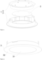
Figure 1 is a schematic diagram of an exploded structure of an easy-to-assemble detachable downlight provided by the embodiments of the present disclosure; -
Figure 2 is a schematic bottom-view structural diagram of an easy-to-assemble detachable downlight provided by the embodiments of the present disclosure; -
Figure 3 is a schematic diagram of assembling of a light source panel and a back seat in an easy-to-assemble detachable downlight provided by the embodiments of the present disclosure; -
Figure 4 is a schematic diagram of assembling of a front hood and a back seat in an easy-to-assemble detachable downlight provided by the embodiments of the present disclosure; -
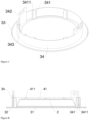
Figure 5 is a schematic diagram of a three-dimensional structure of a back seat in an easy-to-assemble detachable downlight provided by the embodiments of the present disclosure; -
Figure 6 is a schematic diagram of a sectional structure of a back seat in an easy-to-assemble detachable downlight provided by the embodiments of the present disclosure; -
Figure 7 is a schematic diagram of a three-dimensional structure of a front hood in an easy-to-assemble detachable downlight provided by the embodiments of the present disclosure; -
Figure 8 is a schematic diagram of a revolved sectional structure of an easy-to-assemble detachable downlight provided by the embodiments of the present disclosure; -
Figure 9 is a schematic top-view structural diagram of an easy-to-assemble detachable downlight provided by the embodiments of the present disclosure; and -
Figure 10 is a schematic diagram of a structural composition of an easy-to-assemble detachable downlight including a power line and an external driving module provided by the embodiments of the present disclosure. - In the drawings: 1, shell; 2, light source panel; 3, front hood; 31, light-transmitting part; 32, surface ring part; 33, panel; 34, connection plate; 341, convex block; 3411, second thread hole; 342, hanger; 343, fixture block; 4, back seat; 41, back plate; 411, first thread hole; 42, conical ring plate; 43, specially-shaped ring plate; 44, flange; 441, open pore; 442, locating gap; 443, threading gap; 444, bayonet; 51, first screw; 52, second screw; 6, power line; 61, switch; and 7, external driving module.
- In order to make the technical problems, technical solutions and beneficial effects of the present disclosure clearer, the present disclosure is further described below in detail with reference to accompanying drawings and embodiments. It should be understood that the specific embodiments described here are merely to explain the present disclosure, and not intended to limit the present disclosure.
- Referring to
Figure 1 and Figure 2 , an easy-to-assemble detachable downlight provided by the present disclosure is now described. The easy-to-assemble detachable downlight includes ashell 1 and alight source panel 2. Theshell 1 is flat and includes afront hood 3 and aback seat 4. Thefront hood 3 and theback seat 4 are of a one-piece structure. Thefront hood 3 and theback seat 4 are detachably connected and encircle an accommodating cavity. Thefront hood 3 has a light-transmittingpart 31 and asurface ring part 32. Thelight source panel 2 is located in the accommodating cavity and is detachably mounted on theback seat 4. Thelight source panel 2 is provided with a power interface used to be connected to an external power supply. Theback seat 4 conducts and dissipates heat generated by thelight source panel 2, and reflects light emitted by thelight source panel 2 to the light-transmittingpart 31. - Compared with the prior art, the easy-to-assemble detachable downlight provided by the present disclosure has the beneficial effects that by the arrangement of the one-piece
front hood 3 andback seat 4, during production of the downlight, after thelight source panel 2 is mounted to theback seat 4, and thefront hood 3 and theback seat 4 are fastened, the assembling of the product is completed with convenience and high efficiency. Compared with a downlight composed of a surface ring, a light-transmitting hood, a heat dissipation body and a light reflection cup, the easy-to-assemble detachable downlight provided by the present disclosure reduces the number of parts, simplifies the structures of the parts and greatly reduces the design and manufacturing cost. During assembling of the product, the steps of press fitting of the surface ring and the light-transmitting hood and clamping fitting of the heat dissipation body and the light reflection cup are canceled, which simplifies the assembling process and improves the assembling efficiency. Meanwhile, since the parts are detachably connected, thefront hood 3 and theback seat 4 can be conveniently separated, and theshell 1 is disassembled to replace different types oflight source panels 2 to fully meet the use need of customers. In addition, theshell 1 is flat, so that the downlight is relatively thin and can be applicable to a narrow installation space. Theback seat 4 is also flat and has a relatively large heat dissipation area. When thelight source panel 2 is mounted on theback seat 4, a distance to theback seat 4 is very small, so that the heat conduction distance is extremely small, and heat generated by the downlight in the use process can be dissipated in time, which is favorable for prolonging the service life of the downlight. - It should be noted that the
light source panel 2 usually uses the prior art. The power interface is an existing structure on thelight source panel 2. Thelight source panel 2 may use light emitting diodes (LEDs) as a light emitting element. Most of the heat generated by thelight source panel 2 is generated by the light emitting element, and light emitted by thelight source panel 2 is all emitted by the light emitting element. - There are various ways to realize detachable connection between the
light source panel 2 and theback seat 4 as well as between thefront hood 3 and theback seat 4, such as clamping after plugging or threaded connection. A detachable structure is obtained in a method which is well known to the person skilled in the art, and application of the detachable structure to the technical solution formed in the present embodiment shall be deemed to fall within the protection scope of the present disclosure. - The
front hood 3 may be formed by one-piece injection molding and is equivalent to two parts, i.e., a surface ring and a light-transmitting hood, in the prior art. During production of the downlight, there is no longer need to assemble the surface ring and the light-transmitting hood, so that the production efficiency is improved. Theback seat 4 may be formed by performing one-piece stamping on an aluminum material to achieve an extremely good heat dissipation effect. Theback seat 4 is equivalent to two parts, i.e., a heat dissipation body and a light reflection cup, in the prior art. During production of the downlight, there is no need to assemble the heat dissipation body and the light reflection cup, so that the production efficiency is improved. Theback seat 4 enhances the heat dissipation effect, and a fastener for the light reflection cup does not need to be additionally designed, so that the design and manufacturing cost is reduced. - Specifically, the
shell 1 may be circular, and at this time, thefront hood 3 and theback seat 4 are also circular. - In the present disclosure, referring to
Figure 3 and Figure 4 , thelight source panel 2 is connected with theback seat 4 through afirst screw 51, and thefront hood 3 is connected with theback seat 4 through asecond screw 52. Screw connection realizes the detachable connection between thelight source panel 2 and theback seat 4 as well as between thefront hood 3 and theback seat 4. A screw connection structure is simple and convenient to assemble and disassemble. Furthermore, screws are easy to obtain and relatively low in cost. - In the present disclosure, referring to
Figure 5 and Figure 6 , theback seat 4 includes aback plate 41, aconical ring plate 42, and a specially-shapedring plate 43. Afirst thread hole 411 for allowing thefirst screw 51 to be screwed in is formed in theback plate 41, and thelight source panel 2 is mounted on theback plate 41 through thefirst screw 51. The own axis of theconical ring plate 42 is perpendicular to theback plate 41, and one end of theconical ring plate 42 is seamlessly connected with theback plate 41; and an inner side surface of theconical ring plate 42 is a light reflection surface and faces the light-transmittingpart 31. The specially-shapedring plate 43 is connected with thefront hood 3 and fixedly connected with theconical ring plate 42 or theback plate 41. - Specifically, the
light source panel 2 is parallel to theback plate 41. After the assembling is completed, a surface of thelight source panel 2 is opposite to the light-transmittingpart 31 and can emit light to the light-transmittingpart 31. Lateral light emitted by thelight source panel 2 is reflected to the light-transmittingpart 31 by virtue of an inner side surface of theconical ring plate 42, thereby increasing the utilization rate of the light. Theconical ring plate 42 may use its surface to reflect the light, or may reflect the light by means of setting a light reflection layer on a light reflection surface. Moreover, thelight source panel 2 is completely or basically fitted to theback plate 41, so that in a working process of the downlight, the heat generated by thelight source panel 2 may be immediately conducted to theback plate 41 to be quickly dissipated to an external space to prolong the life of the downlight. - In the present disclosure, referring to
Figure 6 , the specially-shapedring plate 43 is conical and surrounds theback plate 41 and theconical ring plate 42; one end of the specially-shapedring plate 43 is connected with theconical ring plate 42; the other end of the specially-shapedring plate 43 is provided with aflange 44; and theflange 44 is provided with anopen pore 441 for allowing thesecond screw 52 to pass through. That is, the specially-shapedring plate 43 is of the same shape as theconical ring plate 42, but they are provided in different directions. FromFigure 6 , theconical ring plate 42 tilts to the inner side, and the specially-shapedring plate 43 tilts to the outer side. - A size of a whole composed of the
back plate 41 and theconical ring plate 42 in an axial direction of the downlight is less than a size of the specially-shapedring plate 43 in the axial direction of the downlight, so that theback plate 41 and theconical ring plate 42 may be completely enclosed in a conical space encircled by the specially-shapedring plate 43. With a relatively small overall thickness, the downlight can well adapt to a narrow installation space. - Specifically, as shown in
Figure 6 , an edge of the lower end of the specially-shapedring plate 43 is seamlessly connected with an edge of the lower end of theconical ring plate 42; an edge of the upper end of the specially-shapedring plate 43 is seamlessly connected with an edge of the inner side of thecircular flange 44; an edge of the upper end of theconical ring plate 42 is seamlessly connected with an edge of theback plate 41; and there are a plurality ofopen pores 441 uniformly distributed in a circumferential direction. The number of theopen pores 441 is consistent with the number of thesecond screws 52, and theopen pores 441 are in one-to-one correspondence to the second screws 52. That is, there are also a plurality ofsecond screws 52 uniformly distributed in the circumferential direction. A tight locking force can be generated to firmly mount thefront hood 3 and theback seat 4 together. - In the present disclosure, referring to
Figure 2 andFigure 7 , thefront hood 3 includes apanel 33; an edge of thepanel 33 is thesurface ring part 32, and thesurface ring part 32 is circular; and the middle part of thepanel 33 is the light-transmittingpart 31. Specifically, a step is arranged between the light-transmittingpart 31 and thesurface ring part 32. - In the present disclosure, referring to
Figure 7 , thefront hood 3 further includes a barrel-shapedconnection plate 34; one end of theconnection plate 34 is fixedly connected with thepanel 33, and the other end of theconnection plate 34 extends towards one side of thepanel 33; aconvex block 341 is arranged on theconnection plate 34; theconvex block 341 is provided with asecond thread hole 3411 that is aligned with theopen pore 441 and allows thesecond screw 52 to be screwed in. Specifically, theconnection plate 34 is perpendicular to thepanel 33 and extends to the upper side of thepanel 33. -
Figure 8 is a schematic diagram of a revolved sectional schematic diagram after thefront hood 3, theback seat 4 and thelight source panel 2 are assembled. Thefirst screw 51 and thesecond screw 52 are not shown in the figures. During assembling, thefirst screw 51 is used to fix thelight source plate 2 to the inner surface of theback plate 41 at first, and then thesecond screw 52 is used to assemble thefront hood 3 and theback seat 4. After the assembling is completed, the thickness of the downlight is basically equal to the height of theconnection plate 34, so that the entire downlight is relatively thin and has a relatively large surface area to facilitate heat dissipation. - As a specific implementation mode of the easy-to-assemble detachable downlight provided by the present disclosure, referring to
Figure 5 ,Figure 7 , andFigure 9 , theconnection plate 34 is provided with ahanger 342; thehanger 342 is used to be connected with an external structure; and thehanger 342 is also used to be aligned with a locatinggap 442 formed in theflange 44 and in clamping fit with the locatinggap 442. Specifically, the top end of thehanger 342 is of a hook-type hanging structure and may be connected to an external structure such as a ceiling. After thehanger 342 is in clamping fit with the locatinggap 442, theopen pore 441 formed in theflange 44 may be aligned with thesecond thread hole 3411 formed in theconnection plate 34 to improve the assembling efficiency. - As a specific implementation mode of the easy-to-assemble detachable downlight provided by the present disclosure, referring to
Figure 5 ,Figure 9, and Figure 10 , the easy-to-assemble detachable downlight further includes apower line 6. One end of thepower line 6 is connected with the power interface, and the other end of thepower line 6 is used to be connected with the external power supply; and theflange 44 is provided with athreading gap 443 for allowing thepower line 6 to pass through. - One end of the
power line 6 is provided with a connector adapting to the power interface on thelight source panel 2. Before assembling of thefront hood 3 and theback seat 4, thepower line 6 and thelight source panel 2 are connected through the connector, and thepower line 6 is arranged in thethreading gap 443. During assembling of thefront hood 3 and theback seat 4, thepower line 6 is located in thethreading gap 443, so that fastening between thefront hood 3 and theback seat 4 cannot be obstructed to enable thefront hood 3 and theback seat 4 to be successfully assembled. - As a specific implementation mode of the easy-to-assemble detachable downlight provided by the present disclosure, referring to
Figure 5 ,Figure 7 , andFigure 9 , two sides of thethreading gap 443 are provided withbayonets 444, and theconnection plate 34 is provided with afixture block 343 that is in clamping fit with thebayonets 444. On the basis of clamping fit between thehanger 342 and the locatinggap 442, the clamping fit between thefixture block 343 and thebayonets 444 further ensures that assembled angles of thefront hood 3 and theback seat 4 are correct, and theopen pore 441 may be just aligned with thesecond thread hole 3411 to screw in thesecond screw 52 to complete the assembling. - As a specific implementation mode of the easy-to-assemble detachable downlight provided by the present disclosure, referring to
Figure 10 , thepower line 6 is provided with aswitch 61 used to control switch on and switch off. The easy-to-assemble detachable downlight further includes anexternal driving module 7 connected between theswitch 61 and the external power supply. Theexternal driving module 7 is used to provide working current for light emitting diodes on thelight source panel 2. In the present embodiment, the downlight takes LEDs as a light source, and thus has many advantages of safety, energy conservation, long service life, and the like. Specifically, two ends of thepower line 6 are provided with plugs, so that thelight source panel 2 and theexternal driving module 7 may be conveniently connected by means of plugging. The plugs, connection structures for the plugs and thelight source panel 2, and connection structures for the plugs and theexternal driving module 7 are all the prior art. Theexternal driving module 7 is the prior art. Using theexternal driving module 7 is favorable for reducing the volume of a downlight main body. Theswitch 61 is also the prior art, which may control whether to feed the working current to the light emitting diodes, thereby controlling the light emitting diodes to be turned on or turned off. - The above descriptions are only the preferred embodiments of the present disclosure, and is not intended to limit the present disclosure.
Claims (5)
- An easy-to-assemble detachable downlight, comprising:a shell (1), which is flat and comprises a front hood (3) and a back seat (4), wherein the front hood (3) and the back seat (4) are of an integrated structure; the front hood (3) and the back seat (4) are detachably connected and encircle an accommodating cavity; the front hood (3) has a light-transmitting part (31) and a surface ring part (32); anda light source panel (2), which is located in the accommodating cavity and is detachably mounted on the back seat (4), wherein the light source panel (2) has a power interface used to be connected to an external power supply;the back seat (4) conducts and dissipates heat generated by the light source panel (2), and reflects light emitted by the light source panel (2) to the light-transmitting part (31);wherein the light source panel (2) is connected with the back seat (4) through a first screw (51), wherein the back seat (4) comprises:a back plate (41), wherein a first thread hole (411) for allowing the first screw (51) to be screwed in is formed in the back plate (41), and the light source panel (2) is mounted on the back plate (41) through the first screw (51);a conical ring plate (42), which has an own axis perpendicular to the back plate (41), wherein one end of the conical ring plate (42) is seamlessly connected with the back plate (41); an inner side surface of the conical ring plate (42) is a light reflection surface and faces the light-transmitting part (31); anda specially-shaped ring plate (43), which is connected with the front hood (3) and fixedly connected with the conical ring plate (42) or the back plate (41);wherein one end of the specially-shaped ring plate (43) is connected with the conical ring plate (42), wherein the front hood (3) comprises a panel (33); an edge of the panel (33) is the surface ring part (32), and the surface ring part (32) is circular; and a middle part of the panel (33) is the light-transmitting part (31);wherein the front hood (3) further comprises a barrel-shaped connection plate (34); one end of the connection plate (34) is fixedly connected with the panel (33), and the other end of the connection plate (34) extends towards one side of the panel (33);characterized in that:the specially-shaped ring plate (43) is conical and surrounds the back plate (41) and the conical ring plate (42);the front hood (10a) is connected with the back seat (4) through a second screw (52);the other end of the specially-shaped ring plate (43) is provided with a flange (44); and the flange (44) is provided with an open pore (441) for allowing the second screw (52) to pass through;and in that a convex block (341) is arranged on the connection plate (34); and the convex block (341) is provided with a second thread hole (3411) that is aligned with the open pore (441) and allows the second screw (52) to be screwed in.
- The easy-to-assemble detachable downlight according to claim 1, wherein the connection plate (34) is provided with a hanger (342); the hanger (342) is used to be connected with an external structure; and the hanger (342) is also used to be aligned with a locating gap (442) formed in the flange (44) and in clamping fit with the locating gap (442).
- The easy-to-assemble detachable downlight according to claim 2, wherein the easy-to-assemble detachable downlight further comprises a power line (6); one end of the power line (6) is connected with the power interface, and the other end of the power line (6) is used to be connected with the external power supply; and the flange (44) is provided with a threading gap (443) for allowing the power line (6) to pass through.
- The easy-to-assemble detachable downlight according to claim 3, wherein two sides of the threading gap (443) are provided with bayonets (444), and the connection plate (34) is provided with a fixture block that is in clamping fit with the bayonets (444).
- The easy-to-assemble detachable downlight according to claim 4, wherein the power line (6) is provided with a switch (61) used to control switch on and switch off; the easy-to-assemble detachable downlight further comprises an external driving module (7) connected between the switch (61) and the external power supply; and the external driving module (7) provides working current for light emitting diodes on the light source panel (2).
Applications Claiming Priority (1)
| Application Number | Priority Date | Filing Date | Title |
|---|---|---|---|
| CN202021572305.7U CN212961184U (en) | 2020-07-31 | 2020-07-31 | Easy-to-assemble detachable downlight |
Publications (2)
| Publication Number | Publication Date |
|---|---|
| EP3945241A1 EP3945241A1 (en) | 2022-02-02 |
| EP3945241B1 true EP3945241B1 (en) | 2024-02-21 |
Family
ID=75345338
Family Applications (1)
| Application Number | Title | Priority Date | Filing Date |
|---|---|---|---|
| EP21186161.2A Active EP3945241B1 (en) | 2020-07-31 | 2021-07-16 | Easy-to-assemble detachable downlight |
Country Status (2)
| Country | Link |
|---|---|
| EP (1) | EP3945241B1 (en) |
| CN (1) | CN212961184U (en) |
Citations (3)
| Publication number | Priority date | Publication date | Assignee | Title |
|---|---|---|---|---|
| WO2011145425A1 (en) * | 2010-05-20 | 2011-11-24 | パナソニック電工株式会社 | Lighting fixture |
| CN204285176U (en) * | 2014-12-27 | 2015-04-22 | 潍坊歌尔光电有限公司 | Concealed frame LED down |
| DE112015002678T5 (en) * | 2014-06-06 | 2017-02-23 | Opple Lighting Co., Ltd. | LED lighting device |
Family Cites Families (4)
| Publication number | Priority date | Publication date | Assignee | Title |
|---|---|---|---|---|
| US20120044695A1 (en) * | 2010-08-20 | 2012-02-23 | Hsu Li Yen | Heat dissipation structure for led lamp |
| CN202024158U (en) * | 2011-04-22 | 2011-11-02 | 东莞健达照明有限公司 | a downlight |
| CN203628395U (en) * | 2013-12-31 | 2014-06-04 | 重庆雷士照明有限公司 | LED (Light-emitting Diode) down lamp |
| CN208312147U (en) * | 2018-06-05 | 2019-01-01 | 惠州雷士光电科技有限公司 | A kind of LED downlight |
-
2020
- 2020-07-31 CN CN202021572305.7U patent/CN212961184U/en active Active
-
2021
- 2021-07-16 EP EP21186161.2A patent/EP3945241B1/en active Active
Patent Citations (3)
| Publication number | Priority date | Publication date | Assignee | Title |
|---|---|---|---|---|
| WO2011145425A1 (en) * | 2010-05-20 | 2011-11-24 | パナソニック電工株式会社 | Lighting fixture |
| DE112015002678T5 (en) * | 2014-06-06 | 2017-02-23 | Opple Lighting Co., Ltd. | LED lighting device |
| CN204285176U (en) * | 2014-12-27 | 2015-04-22 | 潍坊歌尔光电有限公司 | Concealed frame LED down |
Also Published As
| Publication number | Publication date |
|---|---|
| CN212961184U (en) | 2021-04-13 |
| EP3945241A1 (en) | 2022-02-02 |
Similar Documents
| Publication | Publication Date | Title |
|---|---|---|
| EP2151626B1 (en) | High power led lamp | |
| CN201795384U (en) | A snap-on LED spotlight | |
| CN103123061B (en) | Light emitting diode (LED) lamp | |
| CN103307502A (en) | Lamp | |
| CN108105627B (en) | LED lamp capable of adjusting illumination width and/or angle | |
| EP3945241A1 (en) | Easy-to-assemble detachable downlight | |
| CN202203807U (en) | LED down lamp and lamp body thereof | |
| CN217273745U (en) | Multi-angle lens independent assortment light-emitting effect's projecting lamp | |
| CN203907542U (en) | Bulb lamp and lamp panel base thereof | |
| CN203068233U (en) | LED bulb lamp | |
| CN204387866U (en) | A kind of light-diffused cylindrical ceiling lamp | |
| CN213656451U (en) | A distributed pressure-bearing large-depth underwater lighting lamp | |
| CN108644673B (en) | A kind of LED spotlight with simple assembly and its implementation method | |
| CN203068210U (en) | Bulb lamp | |
| CN206694973U (en) | a downlight | |
| CN223448210U (en) | Three-head solar projection lamp | |
| CN222925402U (en) | Lamp set | |
| CN222459376U (en) | Outdoor lighting lamp | |
| CN204372725U (en) | A kind of Novel ceiling Down lamp | |
| CN221858466U (en) | Down lamp and intelligent lighting system | |
| CN208487489U (en) | A kind of explosion-proof illuminating lamp | |
| CN213395038U (en) | Camping lamp with improvement type optical structure | |
| CN220707159U (en) | Anti-dazzle illumination lamp | |
| CN219735265U (en) | High-brightness LED projection lamp | |
| CN212929687U (en) | Energy-saving lamp holder convenient to disassemble and assemble |
Legal Events
| Date | Code | Title | Description |
|---|---|---|---|
| PUAI | Public reference made under article 153(3) epc to a published international application that has entered the european phase |
Free format text: ORIGINAL CODE: 0009012 |
|
| STAA | Information on the status of an ep patent application or granted ep patent |
Free format text: STATUS: THE APPLICATION HAS BEEN PUBLISHED |
|
| AK | Designated contracting states |
Kind code of ref document: A1 Designated state(s): AL AT BE BG CH CY CZ DE DK EE ES FI FR GB GR HR HU IE IS IT LI LT LU LV MC MK MT NL NO PL PT RO RS SE SI SK SM TR |
|
| STAA | Information on the status of an ep patent application or granted ep patent |
Free format text: STATUS: REQUEST FOR EXAMINATION WAS MADE |
|
| 17P | Request for examination filed |
Effective date: 20220513 |
|
| RBV | Designated contracting states (corrected) |
Designated state(s): AL AT BE BG CH CY CZ DE DK EE ES FI FR GB GR HR HU IE IS IT LI LT LU LV MC MK MT NL NO PL PT RO RS SE SI SK SM TR |
|
| GRAP | Despatch of communication of intention to grant a patent |
Free format text: ORIGINAL CODE: EPIDOSNIGR1 |
|
| STAA | Information on the status of an ep patent application or granted ep patent |
Free format text: STATUS: GRANT OF PATENT IS INTENDED |
|
| RIC1 | Information provided on ipc code assigned before grant |
Ipc: F21V 17/16 20060101ALN20230831BHEP Ipc: F21Y 115/10 20160101ALN20230831BHEP Ipc: F21V 29/507 20150101ALI20230831BHEP Ipc: F21V 29/70 20150101ALI20230831BHEP Ipc: F21V 17/12 20060101ALI20230831BHEP Ipc: F21V 15/01 20060101ALI20230831BHEP Ipc: F21S 8/02 20060101AFI20230831BHEP |
|
| RIC1 | Information provided on ipc code assigned before grant |
Ipc: F21V 17/16 20060101ALN20230901BHEP Ipc: F21Y 115/10 20160101ALN20230901BHEP Ipc: F21V 29/507 20150101ALI20230901BHEP Ipc: F21V 29/70 20150101ALI20230901BHEP Ipc: F21V 17/12 20060101ALI20230901BHEP Ipc: F21V 15/01 20060101ALI20230901BHEP Ipc: F21S 8/02 20060101AFI20230901BHEP |
|
| INTG | Intention to grant announced |
Effective date: 20230922 |
|
| GRAS | Grant fee paid |
Free format text: ORIGINAL CODE: EPIDOSNIGR3 |
|
| GRAA | (expected) grant |
Free format text: ORIGINAL CODE: 0009210 |
|
| STAA | Information on the status of an ep patent application or granted ep patent |
Free format text: STATUS: THE PATENT HAS BEEN GRANTED |
|
| AK | Designated contracting states |
Kind code of ref document: B1 Designated state(s): AL AT BE BG CH CY CZ DE DK EE ES FI FR GB GR HR HU IE IS IT LI LT LU LV MC MK MT NL NO PL PT RO RS SE SI SK SM TR |
|
| REG | Reference to a national code |
Ref country code: GB Ref legal event code: FG4D |
|
| REG | Reference to a national code |
Ref country code: CH Ref legal event code: EP |
|
| REG | Reference to a national code |
Ref country code: DE Ref legal event code: R096 Ref document number: 602021009541 Country of ref document: DE |
|
| REG | Reference to a national code |
Ref country code: IE Ref legal event code: FG4D |
|
| REG | Reference to a national code |
Ref country code: LT Ref legal event code: MG9D |
|
| REG | Reference to a national code |
Ref country code: NL Ref legal event code: MP Effective date: 20240221 |
|
| PG25 | Lapsed in a contracting state [announced via postgrant information from national office to epo] |
Ref country code: IS Free format text: LAPSE BECAUSE OF FAILURE TO SUBMIT A TRANSLATION OF THE DESCRIPTION OR TO PAY THE FEE WITHIN THE PRESCRIBED TIME-LIMIT Effective date: 20240621 |
|
| PG25 | Lapsed in a contracting state [announced via postgrant information from national office to epo] |
Ref country code: LT Free format text: LAPSE BECAUSE OF FAILURE TO SUBMIT A TRANSLATION OF THE DESCRIPTION OR TO PAY THE FEE WITHIN THE PRESCRIBED TIME-LIMIT Effective date: 20240221 |
|
| PG25 | Lapsed in a contracting state [announced via postgrant information from national office to epo] |
Ref country code: GR Free format text: LAPSE BECAUSE OF FAILURE TO SUBMIT A TRANSLATION OF THE DESCRIPTION OR TO PAY THE FEE WITHIN THE PRESCRIBED TIME-LIMIT Effective date: 20240522 |
|
| REG | Reference to a national code |
Ref country code: AT Ref legal event code: MK05 Ref document number: 1659395 Country of ref document: AT Kind code of ref document: T Effective date: 20240221 |
|
| PG25 | Lapsed in a contracting state [announced via postgrant information from national office to epo] |
Ref country code: HR Free format text: LAPSE BECAUSE OF FAILURE TO SUBMIT A TRANSLATION OF THE DESCRIPTION OR TO PAY THE FEE WITHIN THE PRESCRIBED TIME-LIMIT Effective date: 20240221 Ref country code: NL Free format text: LAPSE BECAUSE OF FAILURE TO SUBMIT A TRANSLATION OF THE DESCRIPTION OR TO PAY THE FEE WITHIN THE PRESCRIBED TIME-LIMIT Effective date: 20240221 Ref country code: RS Free format text: LAPSE BECAUSE OF FAILURE TO SUBMIT A TRANSLATION OF THE DESCRIPTION OR TO PAY THE FEE WITHIN THE PRESCRIBED TIME-LIMIT Effective date: 20240521 |
|
| PG25 | Lapsed in a contracting state [announced via postgrant information from national office to epo] |
Ref country code: ES Free format text: LAPSE BECAUSE OF FAILURE TO SUBMIT A TRANSLATION OF THE DESCRIPTION OR TO PAY THE FEE WITHIN THE PRESCRIBED TIME-LIMIT Effective date: 20240221 |
|
| PG25 | Lapsed in a contracting state [announced via postgrant information from national office to epo] |
Ref country code: AT Free format text: LAPSE BECAUSE OF FAILURE TO SUBMIT A TRANSLATION OF THE DESCRIPTION OR TO PAY THE FEE WITHIN THE PRESCRIBED TIME-LIMIT Effective date: 20240221 |
|
| PG25 | Lapsed in a contracting state [announced via postgrant information from national office to epo] |
Ref country code: RS Free format text: LAPSE BECAUSE OF FAILURE TO SUBMIT A TRANSLATION OF THE DESCRIPTION OR TO PAY THE FEE WITHIN THE PRESCRIBED TIME-LIMIT Effective date: 20240521 Ref country code: NO Free format text: LAPSE BECAUSE OF FAILURE TO SUBMIT A TRANSLATION OF THE DESCRIPTION OR TO PAY THE FEE WITHIN THE PRESCRIBED TIME-LIMIT Effective date: 20240521 Ref country code: NL Free format text: LAPSE BECAUSE OF FAILURE TO SUBMIT A TRANSLATION OF THE DESCRIPTION OR TO PAY THE FEE WITHIN THE PRESCRIBED TIME-LIMIT Effective date: 20240221 Ref country code: LT Free format text: LAPSE BECAUSE OF FAILURE TO SUBMIT A TRANSLATION OF THE DESCRIPTION OR TO PAY THE FEE WITHIN THE PRESCRIBED TIME-LIMIT Effective date: 20240221 Ref country code: IS Free format text: LAPSE BECAUSE OF FAILURE TO SUBMIT A TRANSLATION OF THE DESCRIPTION OR TO PAY THE FEE WITHIN THE PRESCRIBED TIME-LIMIT Effective date: 20240621 Ref country code: HR Free format text: LAPSE BECAUSE OF FAILURE TO SUBMIT A TRANSLATION OF THE DESCRIPTION OR TO PAY THE FEE WITHIN THE PRESCRIBED TIME-LIMIT Effective date: 20240221 Ref country code: GR Free format text: LAPSE BECAUSE OF FAILURE TO SUBMIT A TRANSLATION OF THE DESCRIPTION OR TO PAY THE FEE WITHIN THE PRESCRIBED TIME-LIMIT Effective date: 20240522 Ref country code: FI Free format text: LAPSE BECAUSE OF FAILURE TO SUBMIT A TRANSLATION OF THE DESCRIPTION OR TO PAY THE FEE WITHIN THE PRESCRIBED TIME-LIMIT Effective date: 20240221 Ref country code: ES Free format text: LAPSE BECAUSE OF FAILURE TO SUBMIT A TRANSLATION OF THE DESCRIPTION OR TO PAY THE FEE WITHIN THE PRESCRIBED TIME-LIMIT Effective date: 20240221 Ref country code: BG Free format text: LAPSE BECAUSE OF FAILURE TO SUBMIT A TRANSLATION OF THE DESCRIPTION OR TO PAY THE FEE WITHIN THE PRESCRIBED TIME-LIMIT Effective date: 20240221 Ref country code: AT Free format text: LAPSE BECAUSE OF FAILURE TO SUBMIT A TRANSLATION OF THE DESCRIPTION OR TO PAY THE FEE WITHIN THE PRESCRIBED TIME-LIMIT Effective date: 20240221 |
|
| PG25 | Lapsed in a contracting state [announced via postgrant information from national office to epo] |
Ref country code: PL Free format text: LAPSE BECAUSE OF FAILURE TO SUBMIT A TRANSLATION OF THE DESCRIPTION OR TO PAY THE FEE WITHIN THE PRESCRIBED TIME-LIMIT Effective date: 20240221 Ref country code: PT Free format text: LAPSE BECAUSE OF FAILURE TO SUBMIT A TRANSLATION OF THE DESCRIPTION OR TO PAY THE FEE WITHIN THE PRESCRIBED TIME-LIMIT Effective date: 20240621 |
|
| PG25 | Lapsed in a contracting state [announced via postgrant information from national office to epo] |
Ref country code: SE Free format text: LAPSE BECAUSE OF FAILURE TO SUBMIT A TRANSLATION OF THE DESCRIPTION OR TO PAY THE FEE WITHIN THE PRESCRIBED TIME-LIMIT Effective date: 20240221 Ref country code: PT Free format text: LAPSE BECAUSE OF FAILURE TO SUBMIT A TRANSLATION OF THE DESCRIPTION OR TO PAY THE FEE WITHIN THE PRESCRIBED TIME-LIMIT Effective date: 20240621 Ref country code: PL Free format text: LAPSE BECAUSE OF FAILURE TO SUBMIT A TRANSLATION OF THE DESCRIPTION OR TO PAY THE FEE WITHIN THE PRESCRIBED TIME-LIMIT Effective date: 20240221 Ref country code: LV Free format text: LAPSE BECAUSE OF FAILURE TO SUBMIT A TRANSLATION OF THE DESCRIPTION OR TO PAY THE FEE WITHIN THE PRESCRIBED TIME-LIMIT Effective date: 20240221 |
|
| PG25 | Lapsed in a contracting state [announced via postgrant information from national office to epo] |
Ref country code: DK Free format text: LAPSE BECAUSE OF FAILURE TO SUBMIT A TRANSLATION OF THE DESCRIPTION OR TO PAY THE FEE WITHIN THE PRESCRIBED TIME-LIMIT Effective date: 20240221 |
|
| PG25 | Lapsed in a contracting state [announced via postgrant information from national office to epo] |
Ref country code: SM Free format text: LAPSE BECAUSE OF FAILURE TO SUBMIT A TRANSLATION OF THE DESCRIPTION OR TO PAY THE FEE WITHIN THE PRESCRIBED TIME-LIMIT Effective date: 20240221 |
|
| PG25 | Lapsed in a contracting state [announced via postgrant information from national office to epo] |
Ref country code: CZ Free format text: LAPSE BECAUSE OF FAILURE TO SUBMIT A TRANSLATION OF THE DESCRIPTION OR TO PAY THE FEE WITHIN THE PRESCRIBED TIME-LIMIT Effective date: 20240221 Ref country code: EE Free format text: LAPSE BECAUSE OF FAILURE TO SUBMIT A TRANSLATION OF THE DESCRIPTION OR TO PAY THE FEE WITHIN THE PRESCRIBED TIME-LIMIT Effective date: 20240221 |
|
| PG25 | Lapsed in a contracting state [announced via postgrant information from national office to epo] |
Ref country code: SK Free format text: LAPSE BECAUSE OF FAILURE TO SUBMIT A TRANSLATION OF THE DESCRIPTION OR TO PAY THE FEE WITHIN THE PRESCRIBED TIME-LIMIT Effective date: 20240221 |
|
| PG25 | Lapsed in a contracting state [announced via postgrant information from national office to epo] |
Ref country code: SM Free format text: LAPSE BECAUSE OF FAILURE TO SUBMIT A TRANSLATION OF THE DESCRIPTION OR TO PAY THE FEE WITHIN THE PRESCRIBED TIME-LIMIT Effective date: 20240221 Ref country code: SK Free format text: LAPSE BECAUSE OF FAILURE TO SUBMIT A TRANSLATION OF THE DESCRIPTION OR TO PAY THE FEE WITHIN THE PRESCRIBED TIME-LIMIT Effective date: 20240221 Ref country code: RO Free format text: LAPSE BECAUSE OF FAILURE TO SUBMIT A TRANSLATION OF THE DESCRIPTION OR TO PAY THE FEE WITHIN THE PRESCRIBED TIME-LIMIT Effective date: 20240221 Ref country code: EE Free format text: LAPSE BECAUSE OF FAILURE TO SUBMIT A TRANSLATION OF THE DESCRIPTION OR TO PAY THE FEE WITHIN THE PRESCRIBED TIME-LIMIT Effective date: 20240221 Ref country code: DK Free format text: LAPSE BECAUSE OF FAILURE TO SUBMIT A TRANSLATION OF THE DESCRIPTION OR TO PAY THE FEE WITHIN THE PRESCRIBED TIME-LIMIT Effective date: 20240221 Ref country code: CZ Free format text: LAPSE BECAUSE OF FAILURE TO SUBMIT A TRANSLATION OF THE DESCRIPTION OR TO PAY THE FEE WITHIN THE PRESCRIBED TIME-LIMIT Effective date: 20240221 |
|
| REG | Reference to a national code |
Ref country code: DE Ref legal event code: R097 Ref document number: 602021009541 Country of ref document: DE |
|
| PG25 | Lapsed in a contracting state [announced via postgrant information from national office to epo] |
Ref country code: IT Free format text: LAPSE BECAUSE OF FAILURE TO SUBMIT A TRANSLATION OF THE DESCRIPTION OR TO PAY THE FEE WITHIN THE PRESCRIBED TIME-LIMIT Effective date: 20240221 |
|
| PLBE | No opposition filed within time limit |
Free format text: ORIGINAL CODE: 0009261 |
|
| STAA | Information on the status of an ep patent application or granted ep patent |
Free format text: STATUS: NO OPPOSITION FILED WITHIN TIME LIMIT |
|
| PG25 | Lapsed in a contracting state [announced via postgrant information from national office to epo] |
Ref country code: IT Free format text: LAPSE BECAUSE OF FAILURE TO SUBMIT A TRANSLATION OF THE DESCRIPTION OR TO PAY THE FEE WITHIN THE PRESCRIBED TIME-LIMIT Effective date: 20240221 |
|
| 26N | No opposition filed |
Effective date: 20241122 |
|
| PG25 | Lapsed in a contracting state [announced via postgrant information from national office to epo] |
Ref country code: MC Free format text: LAPSE BECAUSE OF FAILURE TO SUBMIT A TRANSLATION OF THE DESCRIPTION OR TO PAY THE FEE WITHIN THE PRESCRIBED TIME-LIMIT Effective date: 20240221 |
|
| REG | Reference to a national code |
Ref country code: CH Ref legal event code: PL |
|
| PG25 | Lapsed in a contracting state [announced via postgrant information from national office to epo] |
Ref country code: LU Free format text: LAPSE BECAUSE OF NON-PAYMENT OF DUE FEES Effective date: 20240716 |
|
| PG25 | Lapsed in a contracting state [announced via postgrant information from national office to epo] |
Ref country code: LU Free format text: LAPSE BECAUSE OF NON-PAYMENT OF DUE FEES Effective date: 20240716 |
|
| PG25 | Lapsed in a contracting state [announced via postgrant information from national office to epo] |
Ref country code: CH Free format text: LAPSE BECAUSE OF NON-PAYMENT OF DUE FEES Effective date: 20240731 Ref country code: SI Free format text: LAPSE BECAUSE OF FAILURE TO SUBMIT A TRANSLATION OF THE DESCRIPTION OR TO PAY THE FEE WITHIN THE PRESCRIBED TIME-LIMIT Effective date: 20240221 Ref country code: BE Free format text: LAPSE BECAUSE OF NON-PAYMENT OF DUE FEES Effective date: 20240731 |
|
| REG | Reference to a national code |
Ref country code: BE Ref legal event code: MM Effective date: 20240731 |
|
| PGFP | Annual fee paid to national office [announced via postgrant information from national office to epo] |
Ref country code: GB Payment date: 20250626 Year of fee payment: 5 |
|
| PGFP | Annual fee paid to national office [announced via postgrant information from national office to epo] |
Ref country code: FR Payment date: 20250626 Year of fee payment: 5 |
|
| PG25 | Lapsed in a contracting state [announced via postgrant information from national office to epo] |
Ref country code: IE Free format text: LAPSE BECAUSE OF NON-PAYMENT OF DUE FEES Effective date: 20240716 |
|
| PGFP | Annual fee paid to national office [announced via postgrant information from national office to epo] |
Ref country code: DE Payment date: 20250627 Year of fee payment: 5 |
|
| PG25 | Lapsed in a contracting state [announced via postgrant information from national office to epo] |
Ref country code: CY Free format text: LAPSE BECAUSE OF FAILURE TO SUBMIT A TRANSLATION OF THE DESCRIPTION OR TO PAY THE FEE WITHIN THE PRESCRIBED TIME-LIMIT; INVALID AB INITIO Effective date: 20210716 |
|
| PG25 | Lapsed in a contracting state [announced via postgrant information from national office to epo] |
Ref country code: HU Free format text: LAPSE BECAUSE OF FAILURE TO SUBMIT A TRANSLATION OF THE DESCRIPTION OR TO PAY THE FEE WITHIN THE PRESCRIBED TIME-LIMIT; INVALID AB INITIO Effective date: 20210716 |