EP3945039B1 - Stackable storage system with pressure sensitive lock - Google Patents
Stackable storage system with pressure sensitive lock Download PDFInfo
- Publication number
- EP3945039B1 EP3945039B1 EP20194860.1A EP20194860A EP3945039B1 EP 3945039 B1 EP3945039 B1 EP 3945039B1 EP 20194860 A EP20194860 A EP 20194860A EP 3945039 B1 EP3945039 B1 EP 3945039B1
- Authority
- EP
- European Patent Office
- Prior art keywords
- container
- locking portion
- storage container
- locking
- area
- Prior art date
- Legal status (The legal status is an assumption and is not a legal conclusion. Google has not performed a legal analysis and makes no representation as to the accuracy of the status listed.)
- Active
Links
Images


Classifications
-
- B—PERFORMING OPERATIONS; TRANSPORTING
- B65—CONVEYING; PACKING; STORING; HANDLING THIN OR FILAMENTARY MATERIAL
- B65D—CONTAINERS FOR STORAGE OR TRANSPORT OF ARTICLES OR MATERIALS, e.g. BAGS, BARRELS, BOTTLES, BOXES, CANS, CARTONS, CRATES, DRUMS, JARS, TANKS, HOPPERS, FORWARDING CONTAINERS; ACCESSORIES, CLOSURES, OR FITTINGS THEREFOR; PACKAGING ELEMENTS; PACKAGES
- B65D21/00—Nestable, stackable or joinable containers; Containers of variable capacity
- B65D21/02—Containers specially shaped, or provided with fittings or attachments, to facilitate nesting, stacking, or joining together
- B65D21/0209—Containers specially shaped, or provided with fittings or attachments, to facilitate nesting, stacking, or joining together stackable or joined together one-upon-the-other in the upright or upside-down position
- B65D21/0228—Containers joined together by screw-, bayonet-, snap-fit or the like
-
- B—PERFORMING OPERATIONS; TRANSPORTING
- B25—HAND TOOLS; PORTABLE POWER-DRIVEN TOOLS; MANIPULATORS
- B25H—WORKSHOP EQUIPMENT, e.g. FOR MARKING-OUT WORK; STORAGE MEANS FOR WORKSHOPS
- B25H3/00—Storage means or arrangements for workshops facilitating access to, or handling of, work tools or instruments
- B25H3/02—Boxes
Definitions
- the present invention relates to a storage container system according to the preamble of claim 1.
- a storage container system is known from US 2017/121056 A1 .
- a similar storage container system is known from US 2020/025229 A1 .
- a stackable storage container system with a pressure sensitive lock comprising of a first storage container configured and arranged to be selectively connected to a second storage container when the first storage container is on top of the second storage container.
- Each of the first container and the second container comprises a first locking portion on a bottom side of the container and a second locking portion on a top side of the container. Downward pressure on the first container causes the first locking portion of the first container and the second locking portion of the second container to engage with each other to connect the first container and the second container.
- the first locking portion comprises of a surface and the second locking portion comprises an inclined surface.
- Downward pressure on the first container causes the surface of the first locking portion of the first container and inclined surface of the second locking portion of the second container to slide against each other to connect the first container and the second container.
- the inclined surface of the second locking portion is biased against the respective first container and the second container by an elastic member so that when downward pressure on the first container causes the surface of the first locking portion of the first container and inclined surface of the second locking portion of the second container to slide against each other, the inclined surface of the second locking portion pivots outward and snaps back into place to connect the first container and the second container.
- the second locking portion can comprise of a pivot and a block combined to the pivot wherein the block comprises the inclined surface to slide against the surface of the first locking portion to connect the first container and the second container.
- the second locking portion can comprise of a mounting base securely combined to each container. A first pivot portion is combined to the mounting base. A second pivot portion is combined to the locking member. A pivot combines the first pivot portion of the mounting base and the second pivot portion of the locking member for pivot movement of the locking member with respect to the mounting base.
- the locking member further comprises of a depression for manual movement of the locking member.
- two blocks with one block on each side of the depression can be provided instead of one block. In each instance, the inclined surface of the block slides against a corresponding surface of the first locking portion.
- the present invention provides a latch mechanism configured to secure two containers together automatically, which includes a first locking portion 1 and a second locking portion 2, the first locking portion 1 and the second locking portion 2 can lock each other automatically.
- the first locking portion 1 is located at the bottom of the container, wherein the first locking portion 1 is formed with protrusion 11.
- the second locking portion 2 is located at the top of the container, wherein the second locking portion 2 includes a mounting base 21 provided with locking member 22 and elastic member 5.
- the locking member 22 can be engaged with the protrusion 11 to connected two containers by simply placing one container on top of the other and applying moderate downward pressure to the top container.
- the locking member 22 is pivotally arranged in the mounting base 21 by pivot 221, and has a locking position (please refer to Figs.1-3 ) and a release position (please refer to Fig.7 ).
- the locking member 22 switches between the locking position and the release position by rotating.
- the elastic member 5 is arranged between the locking member 22 and the mounting base 21, and the elastic member 5 biases the locking member 22 to keep it in the locking position. In other words, in the absence of external force, the locking member 22 is in the locking position due to the elasticity of the elastic member 5.
- the related structure of the elastic member 5 we will describe it later.
- first pivot portion 23 in the mounting base 21, and there is a second pivot portion 222 on the locking member 22.
- the pivot 221 pass through the first pivot portion 23 and the second pivot portion 222 to connect the locking member 22 and the mounting base 21, and the locking member 22 can rotate relative to the mounting base 21.
- the first pivot portion 23 is located in the middle of the mounting base 21, and the second pivot portion 222 includes two parts which are arranged at both ends of the locking member 22 separately.
- the first pivot portion 23 is located between the two parts of second pivot portion 222.
- first pivot portion 23 and the second pivot portion 222 can be arranged with other different quantities and arrangements, for example, only one of the first pivot portion and the second pivot portion are provided, and one is arranged on the left, the other one is arranged on the right.
- the first locking portion 1 includes two protrusions 11, wherein each protrusion 11 is provided with an opening 112 and a bottom wall 111.
- the locking member 22 of the second locking portion 2 is provided with two blocks 3.
- the blocks 3 are formed by extending from the inner surface of the locking member 22 toward the direction close to the container, which include an inclined surface 31 and a bottom surface 32, respectively.
- the locking member 22 is in locking position due to the elasticity of elastic member 5 without external force (please refer to Figs.2-3 ).
- two containers need to be connected and locked, just align one container with the other container and apply moderate downward pressure to the top container.
- the bottom wall 111 on the top container and the inclined surface 31 on the bottom container contact and resist each other.
- the bottom wall 111 push the inclined surface 31 to rotate away from the container. In other words, the bottom wall 111 pushes the blocks 3 and the locking member 22 to rotate toward the release position.
- the bottom wall 111 on the top container needs to overcome the elasticity force of the elastic member 5 on the bottom container to push the locking member 22 to rotate toward the release position.
- the top container sinks to a position that can be locked
- the bottom wall 111 on the top container and the inclined surface 31 on the bottom container no longer contact and resist each other, and the bottom wall 111 is located below the bottom surface 32 of the block 3 on the bottom container.
- the locking member 22 has been rotated to the release position.
- the elastic member 5 on the bottom container automatically rotates the locking member 22 on the bottom container back to the locking position.
- the two blocks 3 With the rotate of the locking member 22, the two blocks 3 also rotate and enter the two openings 112 on the top container respectively. When the locking member 22 returns to the locking position, the two blocks 3 also completely enter the two openings 112 on the top container respectively. In this way, the two containers are locked to each other. In short, during the locking process of the two containers, the locking member 22 will automatically complete the rotation from the locking position to the release position and then back to the locking position. Just placing one container on top of the other and applying moderate downward pressure to the top container, the two containers will lock each other automatically. It is worth noting that the application of downward force may also achieved under the natural weight of the top container.
- the bottom wall 111 is provided with a surface 1112.
- Surface 1112 can be at an angle to or parallel with the inclined surface 31 on the block 3. As shown, surface 1112 is an inclined mating surface parallel to the inclined surface 31 on block 3.
- the bottom wall 111 is provided with a hole 114
- the block 3 is provided with a protrusion (not shown) on the bottom surface 32.
- Figs.1-7 there are two protrusions 11 and two corresponding blocks 3. In other embodiment, one or more pairs of protrusion and block may also be provided.
- a depression 224 on the locking member 22 for user's fingers to enter.
- the user can rotate the locking member 22.
- the depression 224 is located between the two blocks 3.
- the user can operate the depression 224 on the bottom container to rotate the locking member 22 from the locking position to the released position.
- the locking member 22 rotates to the released position, the blocks 3 on the locking member 22 disengaged with the openings 112 on the protrusions 11 respectively, and the user can remove the top container.
- the locking member 22 on the bottom container will return to the locking position without the external force, so the user needs to operate the locking member 22 to keep it in the release position while removing the top container. It is not convenient and difficult to complete. It is necessary to provide a structure to keep the locking member 22 in a releasable position, so that the user can easily remove the top container.
- the positioning assembly 4 includes a main body 41 with a through-hole 411, a spring 43 arranged in the through-hole 411, and two ends 42 respectively arranged at both ends of the spring 43.
- the main body 41 received in the mounting portion 225 of the locking member 22.
- the connection of the main body 41 and the mounting portion 225 can be detachable, and the two also can be integrally formed.
- the two ends 42 are exposed to the through-hole 411 (or the main body 41). When pressed by external force, the two ends 42 can be hidden in the through-hole 411 (or the main body 41).
- the mounting portion 225 is located between the two blocks 3 and below the depression 224.
- both the two protrusions 11 on the top container have a side surface 113 close to the positioning assembly 4. Since the two protrusions 11 are symmetrical, only one side surface 113 on one protrusion 11 is described (though they need not be symmetrical).
- the side surface 113 is provided with a first area 61, a second area 62, and a wall 63 for separating the first area 61 and the second area 62.
- First area 61 and second area 62 provide a space for expansion of two ends 42 out of through-hole 411 by spring 43 and wall 63 serves to push two ends 42 into through-hole 411.
- First area 61 and second area 62 can also be formed as notches in side surface 113 that can take any geometrical shape as long as there is space for the arcuate path of travel of two ends 42 from rotation of locking member 22 and wall 63 separating first area 61 and second area 62 to hold locking member in respective positions.
- second area 62 can have a curved shape with a sloped edge 64. As positioning assembly 4 is moved, end 42 is biased outward by spring 43 travels against sloped edge 64. In the locking position, ends 42 are extended outward at the end of the curve furthest away from first area 61.
- positioning assembly 4 can be rotated with respect to two protrusions 11 between three positions, a locking position, a release position, and a holding position.
- the positioning assembly 4 rotates with the locking member 22. During this process, the two ends 42 of the positioning assembly 4 can move back and forth in the second area 62 along sloped edge 64 of the curve. Please refer to Fig.7 , the locking member 22 is in the release position, the blocks 3 are disengaged with the opening 112, and the ends 42 of the positioning assembly 4 are at apex 65 of sloped edge 64 of the curve closest to wall 63 separating first area 61 and second area 62.
- the elastic member 5 is a torsional spring. Both ends of the mounting base 21 are provided with a receiving recess 81 and a resisting side 811. Both ends of the locking member 22 are provided with a stopper 82. The elastic member 5 is disposed in the receiving recess 81, one end is against the resisting side 811, and the other end against the stopper 82. When the locking member 22 rotates from the locking position to the release position or holding position, the stopper 82 also rotates toward the resisting side 811. Furthermore, the stopper 82 is provided with a groove 821 for receiving the end of the elastic member 5.
- a set of limit structure are respectively provided at both ends of the mounting base 21, and symmetrical to each other. In other embodiment, only one set of limit structure can be provided at one end of the mounting base 21.
- two recesses 71 and two notches 72 are provided for receiving the two first locking portions 1 and the two second locking portions 2.
- first locking portion 1 and the second locking portion 2 can be detachably mounted on the container as separate components, or can be integrally formed with the container, also the positions of the first and second locking member on the container can be interchanged.
Landscapes
- Engineering & Computer Science (AREA)
- Mechanical Engineering (AREA)
- Stackable Containers (AREA)
Description
- The present invention relates to a storage container system according to the preamble of
claim 1. Such a storage container system is known fromUS 2017/121056 A1 . A similar storage container system is known fromUS 2020/025229 A1 . - In view of this it is the object of the invention to disclose an improved storage container system that is more efficient, easy to use, modular, and/or multifunctional.
- This object is achieved by a storage container system according to
claim 1. Further embodiments are subject of the dependent claims. - Disclosed is a stackable storage container system with a pressure sensitive lock. The system comprises of a first storage container configured and arranged to be selectively connected to a second storage container when the first storage container is on top of the second storage container. Each of the first container and the second container comprises a first locking portion on a bottom side of the container and a second locking portion on a top side of the container. Downward pressure on the first container causes the first locking portion of the first container and the second locking portion of the second container to engage with each other to connect the first container and the second container.
- More specifically, the first locking portion comprises of a surface and the second locking portion comprises an inclined surface. Downward pressure on the first container causes the surface of the first locking portion of the first container and inclined surface of the second locking portion of the second container to slide against each other to connect the first container and the second container. The inclined surface of the second locking portion is biased against the respective first container and the second container by an elastic member so that when downward pressure on the first container causes the surface of the first locking portion of the first container and inclined surface of the second locking portion of the second container to slide against each other, the inclined surface of the second locking portion pivots outward and snaps back into place to connect the first container and the second container.
- The second locking portion can comprise of a pivot and a block combined to the pivot wherein the block comprises the inclined surface to slide against the surface of the first locking portion to connect the first container and the second container. The second locking portion can comprise of a mounting base securely combined to each container. A first pivot portion is combined to the mounting base. A second pivot portion is combined to the locking member. A pivot combines the first pivot portion of the mounting base and the second pivot portion of the locking member for pivot movement of the locking member with respect to the mounting base.
- In some embodiments, the locking member further comprises of a depression for manual movement of the locking member. Also two blocks with one block on each side of the depression can be provided instead of one block. In each instance, the inclined surface of the block slides against a corresponding surface of the first locking portion.
- These and other features and advantages of the present invention will be better understood by reading the following detailed description, taken together with the drawings wherein:
-
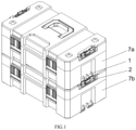
FIG. 1 shows a side perspective view of a first storage container stacked on top of a second storage container and latched together according to an embodiment of this disclosure. -
FIG. 2 shows another side perspective view of the first storage container separated from the second storage container. -
FIG. 3 shows enlarged area A ofFIG. 2 . -
FIG. 4 is an exploded view of the locking member and the mounting base shown inFIG. 3 . -
FIG. 5 is a perspective view of the second locking portion on top of the second storage container. -
FIG. 6 is a close-up view of the second locking portion in the holding position. -
FIG. 7 is a close-up view of the second locking portion in the release position. -
FIG. 8 is a side view of the first container ofFIG. 1 . -
FIG. 9 is a cross-sectional view taken from direction A-A ofFIG. 8 . -
FIG. 10 is a close-up view of area B ofFIG. 9 . - The present invention provides a latch mechanism configured to secure two containers together automatically, which includes a
first locking portion 1 and asecond locking portion 2, thefirst locking portion 1 and thesecond locking portion 2 can lock each other automatically. - Please refer to
Figs. 1-2 , thefirst locking portion 1 is located at the bottom of the container, wherein thefirst locking portion 1 is formed withprotrusion 11. And thesecond locking portion 2 is located at the top of the container, wherein thesecond locking portion 2 includes amounting base 21 provided withlocking member 22 and elastic member 5. Thelocking member 22 can be engaged with theprotrusion 11 to connected two containers by simply placing one container on top of the other and applying moderate downward pressure to the top container. - The
locking member 22 is pivotally arranged in themounting base 21 bypivot 221, and has a locking position (please refer toFigs.1-3 ) and a release position (please refer toFig.7 ). Thelocking member 22 switches between the locking position and the release position by rotating. The elastic member 5 is arranged between thelocking member 22 and themounting base 21, and the elastic member 5 biases thelocking member 22 to keep it in the locking position. In other words, in the absence of external force, thelocking member 22 is in the locking position due to the elasticity of the elastic member 5. Regarding the related structure of the elastic member 5, we will describe it later. - Specifically, please refer to
figs 4-5 , there is afirst pivot portion 23 in themounting base 21, and there is asecond pivot portion 222 on thelocking member 22. Thepivot 221 pass through thefirst pivot portion 23 and thesecond pivot portion 222 to connect thelocking member 22 and themounting base 21, and thelocking member 22 can rotate relative to themounting base 21. In the embodiment, thefirst pivot portion 23 is located in the middle of themounting base 21, and thesecond pivot portion 222 includes two parts which are arranged at both ends of thelocking member 22 separately. When thelocking member 22 and themounting base 21 are pivotally connected to each other, thefirst pivot portion 23 is located between the two parts ofsecond pivot portion 222. In other embodiments, thefirst pivot portion 23 and thesecond pivot portion 222 can be arranged with other different quantities and arrangements, for example, only one of the first pivot portion and the second pivot portion are provided, and one is arranged on the left, the other one is arranged on the right. - Please refer to
Figs.1-4 , thefirst locking portion 1 includes twoprotrusions 11, wherein eachprotrusion 11 is provided with anopening 112 and abottom wall 111. Correspondingly, thelocking member 22 of thesecond locking portion 2 is provided with twoblocks 3. Theblocks 3 are formed by extending from the inner surface of thelocking member 22 toward the direction close to the container, which include aninclined surface 31 and abottom surface 32, respectively. - As described above, the
locking member 22 is in locking position due to the elasticity of elastic member 5 without external force (please refer toFigs.2-3 ). When two containers need to be connected and locked, just align one container with the other container and apply moderate downward pressure to the top container. During the locking process, thebottom wall 111 on the top container and theinclined surface 31 on the bottom container contact and resist each other. With the gradual sinking of the top container, thebottom wall 111 push theinclined surface 31 to rotate away from the container. In other words, thebottom wall 111 pushes theblocks 3 and thelocking member 22 to rotate toward the release position. It is not difficult to understand that thebottom wall 111 on the top container needs to overcome the elasticity force of the elastic member 5 on the bottom container to push thelocking member 22 to rotate toward the release position. When the top container sinks to a position that can be locked, thebottom wall 111 on the top container and theinclined surface 31 on the bottom container no longer contact and resist each other, and thebottom wall 111 is located below thebottom surface 32 of theblock 3 on the bottom container. At this point, thelocking member 22 has been rotated to the release position. At the same time, due to the loss of the resistance of thebottom wall 111 on the top container, the elastic member 5 on the bottom container automatically rotates thelocking member 22 on the bottom container back to the locking position. With the rotate of thelocking member 22, the twoblocks 3 also rotate and enter the twoopenings 112 on the top container respectively. When thelocking member 22 returns to the locking position, the twoblocks 3 also completely enter the twoopenings 112 on the top container respectively. In this way, the two containers are locked to each other. In short, during the locking process of the two containers, thelocking member 22 will automatically complete the rotation from the locking position to the release position and then back to the locking position. Just placing one container on top of the other and applying moderate downward pressure to the top container, the two containers will lock each other automatically. It is worth noting that the application of downward force may also achieved under the natural weight of the top container. - Further, please refer to
Fig.3 , thebottom wall 111 is provided with asurface 1112.Surface 1112 can be at an angle to or parallel with theinclined surface 31 on theblock 3. As shown,surface 1112 is an inclined mating surface parallel to theinclined surface 31 onblock 3. - Further more, please refer to
Fig.3 , thebottom wall 111 is provided with ahole 114, correspondingly, theblock 3 is provided with a protrusion (not shown) on thebottom surface 32. When the lockingmember 22 rotates back to the locking position, theblock 3 enters theopening 112, also the protrusion on thebottom surface 32 engages thehole 114 on thebottom wall 111. - Please refer to
Figs.1-7 , in this embodiment, there are twoprotrusions 11 and twocorresponding blocks 3. In other embodiment, one or more pairs of protrusion and block may also be provided. - Please refer to
Figs.4-5 , there is adepression 224 on the lockingmember 22 for user's fingers to enter. Thus, the user can rotate the locking member 22.In this embodiment, thedepression 224 is located between the twoblocks 3. - When two containers need to be released from each other, the user can operate the
depression 224 on the bottom container to rotate the lockingmember 22 from the locking position to the released position. When the lockingmember 22 rotates to the released position, theblocks 3 on the lockingmember 22 disengaged with theopenings 112 on theprotrusions 11 respectively, and the user can remove the top container. However, due to the elasticity of the elastic member 5, the lockingmember 22 on the bottom container will return to the locking position without the external force, so the user needs to operate the lockingmember 22 to keep it in the release position while removing the top container. It is not convenient and difficult to complete. It is necessary to provide a structure to keep the lockingmember 22 in a releasable position, so that the user can easily remove the top container. - Please refer to
Figs.4-5 , there is shown apositioning assembly 4 on the lockingmember 22. The lockingmember 22 is provided with a mountingportion 225 for receiving thepositioning assembly 4. Specifically, thepositioning assembly 4 includes amain body 41 with a through-hole 411, aspring 43 arranged in the through-hole 411, and two ends 42 respectively arranged at both ends of thespring 43. With reference toFig.5 , shown is themain body 41 received in the mountingportion 225 of the lockingmember 22. It is worth noting that the connection of themain body 41 and the mountingportion 225 can be detachable, and the two also can be integrally formed. In the absence of external force, the two ends 42 are exposed to the through-hole 411 (or the main body 41). When pressed by external force, the two ends 42 can be hidden in the through-hole 411 (or the main body 41). In this embodiment, the mountingportion 225 is located between the twoblocks 3 and below thedepression 224. - Correspondingly, both the two
protrusions 11 on the top container have aside surface 113 close to thepositioning assembly 4. Since the twoprotrusions 11 are symmetrical, only oneside surface 113 on oneprotrusion 11 is described (though they need not be symmetrical). With reference toFigs.3 and8-10 , theside surface 113 is provided with afirst area 61, asecond area 62, and awall 63 for separating thefirst area 61 and thesecond area 62.First area 61 andsecond area 62 provide a space for expansion of two ends 42 out of through-hole 411 byspring 43 andwall 63 serves to push two ends 42 into through-hole 411. -
First area 61 andsecond area 62 can also be formed as notches inside surface 113 that can take any geometrical shape as long as there is space for the arcuate path of travel of two ends 42 from rotation of lockingmember 22 andwall 63 separatingfirst area 61 andsecond area 62 to hold locking member in respective positions. As shown inFigs. 8-10 ,second area 62 can have a curved shape with asloped edge 64. Aspositioning assembly 4 is moved, end 42 is biased outward byspring 43 travels against slopededge 64. In the locking position, ends 42 are extended outward at the end of the curve furthest away fromfirst area 61. At the opposite end at an apex 65 of the curve, ends 42 are pushed inward by slopededge 64 as positioning assembly is moved towardfirst area 61 so that the positioning assembly is in the release position. In total,positioning assembly 4 can be rotated with respect to twoprotrusions 11 between three positions, a locking position, a release position, and a holding position. - When two containers need to be locked, the
positioning assembly 4 rotates with the lockingmember 22. During this process, the two ends 42 of thepositioning assembly 4 can move back and forth in thesecond area 62 along slopededge 64 of the curve. Please refer toFig.7 , the lockingmember 22 is in the release position, theblocks 3 are disengaged with theopening 112, and theends 42 of thepositioning assembly 4 are atapex 65 of slopededge 64 of the curve closest to wall 63 separatingfirst area 61 andsecond area 62. - When two containers need to be released, the user needs to operate the
depression 224 to rotate the lockingmember 22 from the locking position to the release position, and then continue to rotate the lockingmember 22. At this time, because of thewall 63, the two ends 42 of thepositioning assembly 4 are retracted and hidden in the through-hole 411. Until thepositioning assembly 4 crosses thewall 63 and enters thefirst area 61, both ends 42 of thepositioning assembly 4 protrude and exposed to the through-hole 411. The user can no longer operate thedepression 224 now, and the lockingmember 22 rotates toward the locking position due to the elasticity of the elastic member 5. Please refer toFig.6 , the ends 42 against thewall 63, and thepositioning assembly 4 cannot cross thewall 63 to enter thesecond area 62. In other words, the lockingmember 22 cannot return to the locking position, and is held in a released position (named holding position) due to the resistance of thewall 63. - After positioning
assembly 4 crosses over thewall 63 into thefirst area 61, theend 42 protrude and exposed to the through-hole 411 again. Due to the elastic member 5, the lockingmember 22 and theend 42 can rotate back. However, thewall 63 prevents theend 42 from rotating back to thesecond area 62. Theend 42 abuts against thewall 63, so that the lockingmember 22 cannot rotate back, that is, the lockingmember 22 is kept in an releasable position, which is the holding position. When the lockingmember 22 is in the holding position (Fig.6 ), the user can tap the outer side of the lockingmember 22 to make it cross thewall 63, then two containers can be locked again. - Further, a limit structure is provided to limit the rotation angle of the locking
member 22. Please refer toFig.4 , the elastic member 5 is a torsional spring. Both ends of the mountingbase 21 are provided with a receivingrecess 81 and a resistingside 811. Both ends of the lockingmember 22 are provided with astopper 82. The elastic member 5 is disposed in the receivingrecess 81, one end is against the resistingside 811, and the other end against thestopper 82. When the lockingmember 22 rotates from the locking position to the release position or holding position, thestopper 82 also rotates toward the resistingside 811. Furthermore, thestopper 82 is provided with agroove 821 for receiving the end of the elastic member 5. - It should be noted that, in this embodiment, a set of limit structure are respectively provided at both ends of the mounting
base 21, and symmetrical to each other. In other embodiment, only one set of limit structure can be provided at one end of the mountingbase 21. - Please refer to
Fig.2 , tworecesses 71 and twonotches 72 are provided for receiving the twofirst locking portions 1 and the twosecond locking portions 2. - Furthermore, for better align of the two containers, there are four positioning
recesses 73 on the top of the container, correspondingly, the bottom of the container is provided with four positioning protrusions (not shown). - It needs to be clear that the
first locking portion 1 and thesecond locking portion 2 can be detachably mounted on the container as separate components, or can be integrally formed with the container, also the positions of the first and second locking member on the container can be interchanged. - While the principles of the invention have been described herein, it is to be understood by those skilled in the art that this description is made only by way of example and not as a limitation as to the scope of the invention. Other embodiments are contemplated within the scope of the present invention in addition to the exemplary embodiments shown and described herein. Modifications and substitutions by one of ordinary skill in the art are considered to be within the scope of the present invention, which is not to be limited except by the following claims.
Claims (13)
- A stackable storage system comprising:a first storage container (7a) configured and arranged to be selectively connected to a second storage container (7b) when the first storage container is on top of the second storage container (7b);wherein each of the first container (7a) and the second container (7b) comprises a first locking portion (1) on a bottom side of the respective first container (7a) and the second container (7b) and a second locking portion (2) on a top side of the respective first container (7a) and the second container (7b); andwherein downward pressure on the first container (7a) causes the first locking portion (1) of the first container (7a) and the second locking portion (2) of the second container (7b) to engage with each other to connect the first container (7a) and the second container (7b);wherein the first locking portion (1) comprises a protrusion (11) with an opening (112) and a surface (1112) underneath the opening (112) and the second locking portion (2) comprises of a block (3) with an inclined surface (31), wherein downward pressure on the first storage container (7a) causes the surface of the protrusion (11) of the first locking portion (1) of the first storage container (7a) and inclined surface of the block of the second locking portion (2) of the second storage container (7b) to slide against each other to connect the first storage container (7a) and the second storage container (7b);characterized in that there is a positioning assembly (4) combined to a locking member (22) of the second locking portion (2), wherein the locking member (22) comprises the block (3) with the inclined surface and the positioning assembly (4) selectively holds the locking member (22) in one of a locking position, a release position, and a holding position.
- The stackable storage system of claim 1, wherein the first locking portion (1) comprises a surface (1112) and the second locking portion (2) comprises an inclined surface (31), wherein downward pressure on the first storage container (7a) causes the surface (1112) of the first locking portion (1) of the first storage container (7a) and inclined surface (31) of the second locking portion (2) of the second storage container (7b) to slide against each other to connect the first storage container (7a) and the second storage container (7b) .
- The stackable storage system of claim 1 or 2, wherein the inclined surface (31) of the second locking portion (2) is biased against the respective first storage container (7a) and the second storage container (7b) by an elastic member (5) so that when downward pressure on the first storage container (7a) causes the surface (1112) of the first locking portion (1) of the first storage container (7a) and inclined surface (31) of the second locking portion (2) of the second storage container (7b) to slide against each other the inclined surface (31) of the second locking portion (2) pivots outward and snaps back into place to connect the first storage container (7a) and the second storage container (7b).
- The stackable storage system of claim 2 or 3, wherein the second locking portion (2) comprises a pivot (221) and a block (3) combined to the pivot (221) wherein the block (3) comprises the inclined surface (31) to slide against the surface (1112) of the first locking portion (1) to connect the first container storage (7a) and the second storage container (7b), wherein preferably the second locking portion (2) comprises of a mounting base (21) securely combined to the respective first storage container (7a) and the second storage container (7b), a first pivot portion (23) combined to the mounting base (21), a locking member (22), a second pivot portion (222) combined to the locking member (22), and the pivot (221) combining the first pivot portion (23) of the mounting base (21) and the second pivot portion (222) of the locking member (22) for pivot movement of the locking member (22) with respect to the mounting base (21).
- The stackable storage system of claim 4, wherein the locking member (22) further comprises of a depression (224) for manual movement of the locking member (22) and two blocks (3) with one block (3) on each side of the depression (224) wherein the two blocks (3) each comprise an inclined surface (31) to slide against a corresponding surface (1112) of the first locking portion (1), preferably further comprising an elastic member (5) that biases the locking member (22) against the mounting base (21) so that when downward pressure on the first container (7a) causes the surface (1112) of the first locking portion (1) of the first storage container (7a) and inclined surface (31) of the second locking portion (2) of the second storage container (7b) to slide against each other the inclined surface (31) of the second locking portion (2) pivots outward and snaps back into place to connect the first storage container (7a) and the second storage container (7b).
- The stackable storage system of claim 1, characterized in that the positioning assembly (4) further comprises of an outwardly biased end (42) and the protrusion (11) of the first locking portion (1) comprises of a first area (61) and a second area (62) separated by a wall (63), wherein in the locking position the outwardly biased end (42) is positioned in the second area (62) and the end (42) is extending outward to lock the block (3) of the locking member (22) in the opening (112) of the protrusion (11), and wherein in the release position the outwardly biased end (42) is positioned in the second area (62) and the end (42) is pushed inward by an edge of the second area (62).
- The stackable storage system of claim 6, characterized in that in the holding position the outwardly biased end (42) is positioned in the first area (61) and the end (42) is extending outward.
- The stackable storage system of claim 6 or 7, characterized in that the second area (62) has a curved shape.
- The stackable storage system of any of claims 1 to 8, characterized in that the first locking portion (1) comprises a pair of protrusions (11) each with an opening (112) and a surface (1112) underneath the opening (112), and wherein the second locking portion (2) comprises of a pair of blocks (3) each with an inclined surface (31), wherein downward pressure on the first container (7a) causes the surface of the each of the pair of protrusions (11) of the first locking portion (1) of the first storage container (7a) and inclined surface (31) of the pair of blocks (3) of the second locking portion (2) of the second storage container (7b) to slide against each other to connect the first storage container (7a) and the second storage container (7b).
- The stackable storage system of claim 9, characterized in that the second locking portion (2) comprise of a locking member (22) that comprises the pair of blocks (3) and further comprises of a depression (224) positioned between the pair of blocks (3) for manual manipulation of the locking member (22) and a positioning assembly (4) positioned between the pair of blocks (3) for selectively holding the locking member (22) in one of a locking position, a release position, and a holding position.
- The stackable storage system of claim 10, characterized in that the positioning assembly (4) comprises a spring (43) and pair of ends (42) each simultaneously outwardly biased by the spring (43).
- The stackable storage system of claim 11, characterized in that the pair of protrusions (11) each comprise an inner side surface (1112) that face towards each other and further comprise a first area (61) and a second area (62) separated by a wall (63) wherein pair of ends (42) of the positioning assembly (4) are selectively outwardly engaged in the respective first area (61) and the second area (62) and inwardly pushed in by the wall (63).
- The stackable storage system of claim 12, characterized in that in the locking position the outwardly biased ends (42) are positioned in the respective second area (62) and the pair of ends (42) are extending outward to lock the pair of blocks (3) of the locking member (22) in the opening (112) of the protrusion (11), and wherein in the release position the outwardly biased pair of ends (42) are positioned in the second area (62) and the pair of ends (42) are each pushed inward by an edge of the second area (62), wherein preferably the second area (62) has a curved shape.
Applications Claiming Priority (2)
| Application Number | Priority Date | Filing Date | Title |
|---|---|---|---|
| CN202010746598.4A CN111924270B (en) | 2020-07-29 | 2020-07-29 | Automatic interlocking structure, storage box and storage box assembly |
| US17/010,975 US11155382B1 (en) | 2020-07-29 | 2020-09-03 | Stackable storage system with pressure sensitive lock |
Publications (3)
| Publication Number | Publication Date |
|---|---|
| EP3945039A1 EP3945039A1 (en) | 2022-02-02 |
| EP3945039B1 true EP3945039B1 (en) | 2023-07-05 |
| EP3945039C0 EP3945039C0 (en) | 2023-07-05 |
Family
ID=72474092
Family Applications (1)
| Application Number | Title | Priority Date | Filing Date |
|---|---|---|---|
| EP20194860.1A Active EP3945039B1 (en) | 2020-07-29 | 2020-09-07 | Stackable storage system with pressure sensitive lock |
Country Status (2)
| Country | Link |
|---|---|
| EP (1) | EP3945039B1 (en) |
| AU (1) | AU2020230227B1 (en) |
Families Citing this family (2)
| Publication number | Priority date | Publication date | Assignee | Title |
|---|---|---|---|---|
| CN116408762B (en) * | 2023-03-31 | 2025-09-26 | 宁波明良智能家居科技有限公司 | A stacking tool box |
| US20240351183A1 (en) * | 2023-04-21 | 2024-10-24 | Kevin Boenisch | Storage System |
Family Cites Families (8)
| Publication number | Priority date | Publication date | Assignee | Title |
|---|---|---|---|---|
| DE202015005752U1 (en) * | 2015-08-18 | 2016-11-21 | Plaston Ag | Stackable case with coupling connection and fuse |
| DE102015013053B4 (en) * | 2015-10-08 | 2022-03-24 | Plaston Ag | Stackable case with connection device |
| US9701443B2 (en) * | 2015-11-02 | 2017-07-11 | Compass Corporation | Set of stackable tool boxes |
| DE202015106823U1 (en) * | 2015-12-15 | 2017-03-16 | Bs Systems Gmbh & Co. Kg | Container, transport box and transport box system |
| DE102016112855A1 (en) * | 2016-07-13 | 2018-01-18 | Bs Systems Gmbh & Co. Kg | Stackable system tray |
| DE102016112853A1 (en) * | 2016-07-13 | 2018-01-18 | Bs Systems Gmbh & Co. Kg | Stackable system tray |
| DE102017128493B3 (en) * | 2017-11-30 | 2018-08-16 | Bs Systems Gmbh & Co. Kg | Stackable system container and transport system |
| US11486427B2 (en) * | 2018-07-18 | 2022-11-01 | The Stanley Works Israel Ltd. | Stacking latch mechanism |
-
2020
- 2020-09-07 EP EP20194860.1A patent/EP3945039B1/en active Active
- 2020-09-07 AU AU2020230227A patent/AU2020230227B1/en active Active
Also Published As
| Publication number | Publication date |
|---|---|
| EP3945039C0 (en) | 2023-07-05 |
| EP3945039A1 (en) | 2022-02-02 |
| AU2020230227B1 (en) | 2021-10-21 |
Similar Documents
| Publication | Publication Date | Title |
|---|---|---|
| US11155382B1 (en) | Stackable storage system with pressure sensitive lock | |
| US12195230B2 (en) | Stackable storage system | |
| US6334346B1 (en) | Numeral lock with resettable feature | |
| EP0221749B1 (en) | Recording medium storage case | |
| US20050044717A1 (en) | Folding knife with lock mechanism | |
| EP3945039A1 (en) | Stackable storage system with pressure sensitive lock | |
| US20200295506A1 (en) | Electric device | |
| US11090820B1 (en) | Blade holder for assembling a replaceable blade | |
| US4515424A (en) | Support structure for IC package and having removable closure | |
| GB2372244A (en) | Multi-layered cosmetic case | |
| US6283523B1 (en) | Safety hook with immobilizable locking lever | |
| KR101320193B1 (en) | Device for positioning and holding an emergency key | |
| WO2019130925A1 (en) | Push-button switch | |
| CN107104366A (en) | Electrical equipment for track installation | |
| CN120265526A (en) | A system and method for securing a container | |
| US6767229B1 (en) | Protective cover and electric outlet arrangement | |
| US7328948B2 (en) | Child seat | |
| KR100215604B1 (en) | Container for storing a plurality of cheque cards | |
| US20070073464A1 (en) | Safety seat assembly | |
| WO2023230852A1 (en) | Locking connecting device and combined container | |
| CN100446994C (en) | Binder with locking mechanism | |
| EP1154169B1 (en) | Connector assembly with a lock of the bayonet type | |
| JPH08330023A (en) | Lever connector | |
| EP3297099B1 (en) | Latch for locking a connector in an electrical and/or telecommunication network | |
| US20250178221A1 (en) | Handle Holder of Blade Tool |
Legal Events
| Date | Code | Title | Description |
|---|---|---|---|
| PUAI | Public reference made under article 153(3) epc to a published international application that has entered the european phase |
Free format text: ORIGINAL CODE: 0009012 |
|
| STAA | Information on the status of an ep patent application or granted ep patent |
Free format text: STATUS: THE APPLICATION HAS BEEN PUBLISHED |
|
| AK | Designated contracting states |
Kind code of ref document: A1 Designated state(s): AL AT BE BG CH CY CZ DE DK EE ES FI FR GB GR HR HU IE IS IT LI LT LU LV MC MK MT NL NO PL PT RO RS SE SI SK SM TR |
|
| STAA | Information on the status of an ep patent application or granted ep patent |
Free format text: STATUS: REQUEST FOR EXAMINATION WAS MADE |
|
| 17P | Request for examination filed |
Effective date: 20220207 |
|
| RBV | Designated contracting states (corrected) |
Designated state(s): AL AT BE BG CH CY CZ DE DK EE ES FI FR GB GR HR HU IE IS IT LI LT LU LV MC MK MT NL NO PL PT RO RS SE SI SK SM TR |
|
| GRAP | Despatch of communication of intention to grant a patent |
Free format text: ORIGINAL CODE: EPIDOSNIGR1 |
|
| STAA | Information on the status of an ep patent application or granted ep patent |
Free format text: STATUS: GRANT OF PATENT IS INTENDED |
|
| RIC1 | Information provided on ipc code assigned before grant |
Ipc: B25H 3/02 20060101ALI20230117BHEP Ipc: B65D 21/02 20060101AFI20230117BHEP |
|
| INTG | Intention to grant announced |
Effective date: 20230203 |
|
| GRAS | Grant fee paid |
Free format text: ORIGINAL CODE: EPIDOSNIGR3 |
|
| GRAA | (expected) grant |
Free format text: ORIGINAL CODE: 0009210 |
|
| STAA | Information on the status of an ep patent application or granted ep patent |
Free format text: STATUS: THE PATENT HAS BEEN GRANTED |
|
| AK | Designated contracting states |
Kind code of ref document: B1 Designated state(s): AL AT BE BG CH CY CZ DE DK EE ES FI FR GB GR HR HU IE IS IT LI LT LU LV MC MK MT NL NO PL PT RO RS SE SI SK SM TR |
|
| REG | Reference to a national code |
Ref country code: CH Ref legal event code: EP |
|
| REG | Reference to a national code |
Ref country code: AT Ref legal event code: REF Ref document number: 1584653 Country of ref document: AT Kind code of ref document: T Effective date: 20230715 |
|
| REG | Reference to a national code |
Ref country code: DE Ref legal event code: R096 Ref document number: 602020013224 Country of ref document: DE |
|
| REG | Reference to a national code |
Ref country code: IE Ref legal event code: FG4D |
|
| U01 | Request for unitary effect filed |
Effective date: 20230807 |
|
| U07 | Unitary effect registered |
Designated state(s): AT BE BG DE DK EE FI FR IT LT LU LV MT NL PT SE SI Effective date: 20230811 |
|
| REG | Reference to a national code |
Ref country code: LT Ref legal event code: MG9D |
|
| U20 | Renewal fee for the european patent with unitary effect paid |
Year of fee payment: 4 Effective date: 20230926 |
|
| PG25 | Lapsed in a contracting state [announced via postgrant information from national office to epo] |
Ref country code: GR Free format text: LAPSE BECAUSE OF FAILURE TO SUBMIT A TRANSLATION OF THE DESCRIPTION OR TO PAY THE FEE WITHIN THE PRESCRIBED TIME-LIMIT Effective date: 20231006 |
|
| PG25 | Lapsed in a contracting state [announced via postgrant information from national office to epo] |
Ref country code: ES Free format text: LAPSE BECAUSE OF FAILURE TO SUBMIT A TRANSLATION OF THE DESCRIPTION OR TO PAY THE FEE WITHIN THE PRESCRIBED TIME-LIMIT Effective date: 20230705 |
|
| PG25 | Lapsed in a contracting state [announced via postgrant information from national office to epo] |
Ref country code: IS Free format text: LAPSE BECAUSE OF FAILURE TO SUBMIT A TRANSLATION OF THE DESCRIPTION OR TO PAY THE FEE WITHIN THE PRESCRIBED TIME-LIMIT Effective date: 20231105 |
|
| PG25 | Lapsed in a contracting state [announced via postgrant information from national office to epo] |
Ref country code: RS Free format text: LAPSE BECAUSE OF FAILURE TO SUBMIT A TRANSLATION OF THE DESCRIPTION OR TO PAY THE FEE WITHIN THE PRESCRIBED TIME-LIMIT Effective date: 20230705 Ref country code: NO Free format text: LAPSE BECAUSE OF FAILURE TO SUBMIT A TRANSLATION OF THE DESCRIPTION OR TO PAY THE FEE WITHIN THE PRESCRIBED TIME-LIMIT Effective date: 20231005 Ref country code: IS Free format text: LAPSE BECAUSE OF FAILURE TO SUBMIT A TRANSLATION OF THE DESCRIPTION OR TO PAY THE FEE WITHIN THE PRESCRIBED TIME-LIMIT Effective date: 20231105 Ref country code: HR Free format text: LAPSE BECAUSE OF FAILURE TO SUBMIT A TRANSLATION OF THE DESCRIPTION OR TO PAY THE FEE WITHIN THE PRESCRIBED TIME-LIMIT Effective date: 20230705 Ref country code: GR Free format text: LAPSE BECAUSE OF FAILURE TO SUBMIT A TRANSLATION OF THE DESCRIPTION OR TO PAY THE FEE WITHIN THE PRESCRIBED TIME-LIMIT Effective date: 20231006 Ref country code: ES Free format text: LAPSE BECAUSE OF FAILURE TO SUBMIT A TRANSLATION OF THE DESCRIPTION OR TO PAY THE FEE WITHIN THE PRESCRIBED TIME-LIMIT Effective date: 20230705 |
|
| PG25 | Lapsed in a contracting state [announced via postgrant information from national office to epo] |
Ref country code: PL Free format text: LAPSE BECAUSE OF FAILURE TO SUBMIT A TRANSLATION OF THE DESCRIPTION OR TO PAY THE FEE WITHIN THE PRESCRIBED TIME-LIMIT Effective date: 20230705 |
|
| REG | Reference to a national code |
Ref country code: DE Ref legal event code: R097 Ref document number: 602020013224 Country of ref document: DE |
|
| PG25 | Lapsed in a contracting state [announced via postgrant information from national office to epo] |
Ref country code: SM Free format text: LAPSE BECAUSE OF FAILURE TO SUBMIT A TRANSLATION OF THE DESCRIPTION OR TO PAY THE FEE WITHIN THE PRESCRIBED TIME-LIMIT Effective date: 20230705 Ref country code: RO Free format text: LAPSE BECAUSE OF FAILURE TO SUBMIT A TRANSLATION OF THE DESCRIPTION OR TO PAY THE FEE WITHIN THE PRESCRIBED TIME-LIMIT Effective date: 20230705 Ref country code: CZ Free format text: LAPSE BECAUSE OF FAILURE TO SUBMIT A TRANSLATION OF THE DESCRIPTION OR TO PAY THE FEE WITHIN THE PRESCRIBED TIME-LIMIT Effective date: 20230705 Ref country code: SK Free format text: LAPSE BECAUSE OF FAILURE TO SUBMIT A TRANSLATION OF THE DESCRIPTION OR TO PAY THE FEE WITHIN THE PRESCRIBED TIME-LIMIT Effective date: 20230705 |
|
| REG | Reference to a national code |
Ref country code: CH Ref legal event code: PL |
|
| PLBE | No opposition filed within time limit |
Free format text: ORIGINAL CODE: 0009261 |
|
| STAA | Information on the status of an ep patent application or granted ep patent |
Free format text: STATUS: NO OPPOSITION FILED WITHIN TIME LIMIT |
|
| PG25 | Lapsed in a contracting state [announced via postgrant information from national office to epo] |
Ref country code: MC Free format text: LAPSE BECAUSE OF FAILURE TO SUBMIT A TRANSLATION OF THE DESCRIPTION OR TO PAY THE FEE WITHIN THE PRESCRIBED TIME-LIMIT Effective date: 20230705 |
|
| 26N | No opposition filed |
Effective date: 20240408 |
|
| REG | Reference to a national code |
Ref country code: IE Ref legal event code: MM4A |
|
| PG25 | Lapsed in a contracting state [announced via postgrant information from national office to epo] |
Ref country code: IE Free format text: LAPSE BECAUSE OF NON-PAYMENT OF DUE FEES Effective date: 20230907 |
|
| PG25 | Lapsed in a contracting state [announced via postgrant information from national office to epo] |
Ref country code: CH Free format text: LAPSE BECAUSE OF NON-PAYMENT OF DUE FEES Effective date: 20230930 |
|
| PG25 | Lapsed in a contracting state [announced via postgrant information from national office to epo] |
Ref country code: IE Free format text: LAPSE BECAUSE OF NON-PAYMENT OF DUE FEES Effective date: 20230907 Ref country code: CH Free format text: LAPSE BECAUSE OF NON-PAYMENT OF DUE FEES Effective date: 20230930 |
|
| U20 | Renewal fee for the european patent with unitary effect paid |
Year of fee payment: 5 Effective date: 20240925 |
|
| GBPC | Gb: european patent ceased through non-payment of renewal fee |
Effective date: 20240907 |
|
| PG25 | Lapsed in a contracting state [announced via postgrant information from national office to epo] |
Ref country code: GB Free format text: LAPSE BECAUSE OF NON-PAYMENT OF DUE FEES Effective date: 20240907 |
|
| PG25 | Lapsed in a contracting state [announced via postgrant information from national office to epo] |
Ref country code: CY Free format text: LAPSE BECAUSE OF FAILURE TO SUBMIT A TRANSLATION OF THE DESCRIPTION OR TO PAY THE FEE WITHIN THE PRESCRIBED TIME-LIMIT; INVALID AB INITIO Effective date: 20200907 |
|
| PG25 | Lapsed in a contracting state [announced via postgrant information from national office to epo] |
Ref country code: HU Free format text: LAPSE BECAUSE OF FAILURE TO SUBMIT A TRANSLATION OF THE DESCRIPTION OR TO PAY THE FEE WITHIN THE PRESCRIBED TIME-LIMIT; INVALID AB INITIO Effective date: 20200907 |
|
| U20 | Renewal fee for the european patent with unitary effect paid |
Year of fee payment: 6 Effective date: 20250924 |
|
| PG25 | Lapsed in a contracting state [announced via postgrant information from national office to epo] |
Ref country code: TR Free format text: LAPSE BECAUSE OF FAILURE TO SUBMIT A TRANSLATION OF THE DESCRIPTION OR TO PAY THE FEE WITHIN THE PRESCRIBED TIME-LIMIT Effective date: 20230705 |