EP3944979A1 - Torque control method for controlling driving torque of an electric vehicle and related device - Google Patents
Torque control method for controlling driving torque of an electric vehicle and related device Download PDFInfo
- Publication number
- EP3944979A1 EP3944979A1 EP20208911.6A EP20208911A EP3944979A1 EP 3944979 A1 EP3944979 A1 EP 3944979A1 EP 20208911 A EP20208911 A EP 20208911A EP 3944979 A1 EP3944979 A1 EP 3944979A1
- Authority
- EP
- European Patent Office
- Prior art keywords
- torque
- signal
- shut
- absolute value
- judgment
- Prior art date
- Legal status (The legal status is an assumption and is not a legal conclusion. Google has not performed a legal analysis and makes no representation as to the accuracy of the status listed.)
- Granted
Links
Images


Classifications
-
- B—PERFORMING OPERATIONS; TRANSPORTING
- B60—VEHICLES IN GENERAL
- B60L—PROPULSION OF ELECTRICALLY-PROPELLED VEHICLES; SUPPLYING ELECTRIC POWER FOR AUXILIARY EQUIPMENT OF ELECTRICALLY-PROPELLED VEHICLES; ELECTRODYNAMIC BRAKE SYSTEMS FOR VEHICLES IN GENERAL; MAGNETIC SUSPENSION OR LEVITATION FOR VEHICLES; MONITORING OPERATING VARIABLES OF ELECTRICALLY-PROPELLED VEHICLES; ELECTRIC SAFETY DEVICES FOR ELECTRICALLY-PROPELLED VEHICLES
- B60L3/00—Electric devices on electrically-propelled vehicles for safety purposes; Monitoring operating variables, e.g. speed, deceleration or energy consumption
- B60L3/0023—Detecting, eliminating, remedying or compensating for drive train abnormalities, e.g. failures within the drive train
- B60L3/0084—Detecting, eliminating, remedying or compensating for drive train abnormalities, e.g. failures within the drive train relating to control modules
-
- B—PERFORMING OPERATIONS; TRANSPORTING
- B60—VEHICLES IN GENERAL
- B60L—PROPULSION OF ELECTRICALLY-PROPELLED VEHICLES; SUPPLYING ELECTRIC POWER FOR AUXILIARY EQUIPMENT OF ELECTRICALLY-PROPELLED VEHICLES; ELECTRODYNAMIC BRAKE SYSTEMS FOR VEHICLES IN GENERAL; MAGNETIC SUSPENSION OR LEVITATION FOR VEHICLES; MONITORING OPERATING VARIABLES OF ELECTRICALLY-PROPELLED VEHICLES; ELECTRIC SAFETY DEVICES FOR ELECTRICALLY-PROPELLED VEHICLES
- B60L15/00—Methods, circuits, or devices for controlling the traction-motor speed of electrically-propelled vehicles
- B60L15/20—Methods, circuits, or devices for controlling the traction-motor speed of electrically-propelled vehicles for control of the vehicle or its driving motor to achieve a desired performance, e.g. speed, torque, programmed variation of speed
-
- B—PERFORMING OPERATIONS; TRANSPORTING
- B60—VEHICLES IN GENERAL
- B60L—PROPULSION OF ELECTRICALLY-PROPELLED VEHICLES; SUPPLYING ELECTRIC POWER FOR AUXILIARY EQUIPMENT OF ELECTRICALLY-PROPELLED VEHICLES; ELECTRODYNAMIC BRAKE SYSTEMS FOR VEHICLES IN GENERAL; MAGNETIC SUSPENSION OR LEVITATION FOR VEHICLES; MONITORING OPERATING VARIABLES OF ELECTRICALLY-PROPELLED VEHICLES; ELECTRIC SAFETY DEVICES FOR ELECTRICALLY-PROPELLED VEHICLES
- B60L2240/00—Control parameters of input or output; Target parameters
- B60L2240/40—Drive Train control parameters
- B60L2240/42—Drive Train control parameters related to electric machines
- B60L2240/421—Speed
-
- B—PERFORMING OPERATIONS; TRANSPORTING
- B60—VEHICLES IN GENERAL
- B60L—PROPULSION OF ELECTRICALLY-PROPELLED VEHICLES; SUPPLYING ELECTRIC POWER FOR AUXILIARY EQUIPMENT OF ELECTRICALLY-PROPELLED VEHICLES; ELECTRODYNAMIC BRAKE SYSTEMS FOR VEHICLES IN GENERAL; MAGNETIC SUSPENSION OR LEVITATION FOR VEHICLES; MONITORING OPERATING VARIABLES OF ELECTRICALLY-PROPELLED VEHICLES; ELECTRIC SAFETY DEVICES FOR ELECTRICALLY-PROPELLED VEHICLES
- B60L2240/00—Control parameters of input or output; Target parameters
- B60L2240/40—Drive Train control parameters
- B60L2240/42—Drive Train control parameters related to electric machines
- B60L2240/423—Torque
-
- Y—GENERAL TAGGING OF NEW TECHNOLOGICAL DEVELOPMENTS; GENERAL TAGGING OF CROSS-SECTIONAL TECHNOLOGIES SPANNING OVER SEVERAL SECTIONS OF THE IPC; TECHNICAL SUBJECTS COVERED BY FORMER USPC CROSS-REFERENCE ART COLLECTIONS [XRACs] AND DIGESTS
- Y02—TECHNOLOGIES OR APPLICATIONS FOR MITIGATION OR ADAPTATION AGAINST CLIMATE CHANGE
- Y02T—CLIMATE CHANGE MITIGATION TECHNOLOGIES RELATED TO TRANSPORTATION
- Y02T10/00—Road transport of goods or passengers
- Y02T10/60—Other road transportation technologies with climate change mitigation effect
- Y02T10/64—Electric machine technologies in electromobility
-
- Y—GENERAL TAGGING OF NEW TECHNOLOGICAL DEVELOPMENTS; GENERAL TAGGING OF CROSS-SECTIONAL TECHNOLOGIES SPANNING OVER SEVERAL SECTIONS OF THE IPC; TECHNICAL SUBJECTS COVERED BY FORMER USPC CROSS-REFERENCE ART COLLECTIONS [XRACs] AND DIGESTS
- Y02—TECHNOLOGIES OR APPLICATIONS FOR MITIGATION OR ADAPTATION AGAINST CLIMATE CHANGE
- Y02T—CLIMATE CHANGE MITIGATION TECHNOLOGIES RELATED TO TRANSPORTATION
- Y02T10/00—Road transport of goods or passengers
- Y02T10/60—Other road transportation technologies with climate change mitigation effect
- Y02T10/72—Electric energy management in electromobility
Definitions
- the invention relates to the field of automobile safety technologies, and in particular to a torque control method for controlling driving torque of an electric vehicle and a related device.
- Driving torque is an important factor that affects the driving of the automobile, and whether the torque can be safely controlled or not directly affects the safety of the automobile.
- the driving torque is adjusted by a torque controller in an electric vehicle. This results in a lower fault tolerance rate and a poor safety of torque control.
- the invention provides a torque control method for controlling driving torque of an electric vehicle in which a processing device can judge whether a shut-off signal sent by a first or second torque controller is obtained respectively so that a redundant system is formed by the two torque controllers, thereby avoiding that the torque cannot be accurately controlled due to the damage of one torque controller and improving the safety and reliability of the torque control.
- Embodiments of the invention disclose the following technical solutions.
- the embodiments of the invention provide a torque control method for controlling driving torque of an electric vehicle including the steps of:
- the first shut-off signal is generated by the steps of:
- the torque deviation threshold is determined according to electric vehicle parameters corresponding to the target vehicle.
- the method further includes, before performing the first judgment, the steps of:
- the first short circuit signal is generated by the steps of:
- the motor rotation speed threshold is determined according to motor parameters of the target vehicle.
- the first shut-off signal comprises:
- the embodiments of the invention provide a torque control device for controlling driving torque of an electric vehicle comprising:
- the first shut-off signal is generated by the steps of:
- the torque deviation threshold is determined according to electric vehicle parameters corresponding to the target vehicle.
- the invention provides the torque control method in which the processing device can judge whether the first shut-off signal sent by the first torque controller or the second shut-off signal sent by the second torque controller is obtained respectively. If the processing device judges that at least one of the signals has been obtained, then outputs the first stop signal to stop outputting the torque.
- the processing device can receive the signals of the first and second torque controllers so that a redundant system is formed between the two torque controllers. If either one of the controllers is damaged, the processing device can still perform the torque control by means of the other controller, thereby improving the safety of the torque control and reducing the probability of risks in the process of driving a vehicle.
- Driving torque control is one of important factors related to safety in driving an automobile. If the torque control fails, the automobile may encounter a series of problems, such as the speed of the automobile is unable to be adjusted or the automobile is unable to be controlled sensitively, seriously threatening the personal safety of users.
- the driving torque control is performed by a torque controller in an electric vehicle.
- the torque controller breaks down, it will become impossible to control the torque of the vehicle well.
- the safety of the vehicle deteriorates.
- the invention provides a torque control method for controlling driving torque of an electric vehicle in which a processing device can judge whether a shut-off signal sent by a first or second torque controller is obtained respectively so that a redundant system is formed between the two torque controllers, thereby avoiding that the torque cannot be accurately controlled due to the damage of one torque controller and improving the safety and reliability of the torque control.
- the method can be applied by the processing device with a torque control function, such as a terminal device or a server.
- the method can be executed by the terminal device or the server separately, or can also be executed by a network scenario where the terminal device and the server communicate and cooperate with each other.
- the terminal device may be a computer or the like.
- the server can be understood as an application server or a web server. In an actual deployment, the server can be an independent server or a cluster server. While the technical solutions can be implemented in a hardware environment such as an ARM processor and an X86 processor, the technical solutions also can be implemented in a software environment such as an Android platform, Windows XP and above operation systems or a Linux operation system.
- FIG. 1 is a flowchart of a torque control method for controlling driving torque of an electric vehicle provided by an embodiment of the invention, the method includes: S101: performing a first judgment.
- a torque controller in the vehicle will send out various signals for torque control, among which, a shut-off signal to shut off a subsequent adjustment of the torque is sent out when the torque of the vehicle is abnormal, for example, when a present actual torque of the vehicle far exceeds a torque requested in the vehicle, in order to prevent a danger of driving the vehicle.
- two torque controllers e.g., two torque control chips, namely first and second torque controllers
- the two torque controllers can monitor and analyze driving conditions of the target vehicle and determine whether the present torque of the target vehicle is abnormal. Multiple ways may be used by the torque controllers to judge whether the torque is abnormal. In a possible implemented way, the torque controllers may determine the actual torque of the target vehicle by means of a three-phase current and a rotor position corresponding to the target vehicle.
- the first and second torque controllers both can send the shut-off signal to a processing device.
- the processing device may perform a first judgment to judge whether a first shut-off signal sent by the first torque controller is obtained.
- the processing device may further perform a second judgment to judge whether a second shut-off signal sent by the second torque controller is obtained.
- the processing device may output the first stop signal to stop outputting a torque.
- the invention provides the torque control method in which the processing device can judge whether the first shut-off signal sent by the first torque controller or the second shut-off signal sent by the second torque controller is obtained respectively. If the processing device judges that the at least one of the signals has been obtained, then outputs the first stop signal to stop outputting the torque.
- the processing device can receive the signals of the first and second torque controllers so that a redundant system is formed between the two torque controllers. If either one of the controllers is damaged, the processing device can still perform the torque control by means of the other controller, thereby improving the safety of the torque control and reducing the probability of risks in the process of driving the vehicle.
- the first shut-off signal may be generated by the steps of judging whether the absolute value of an actual torque value of the target vehicle is not less than the absolute value of a torque abnormality threshold by the first torque controller.
- the torque abnormality threshold is a threshold for identifying that the torque of the vehicle is in an abnormal state, and the torque abnormality threshold can be determined according to a torque request value and a torque deviation threshold.
- the torque request value refers to a torque value actually requested in the target vehicle when performing the torque control and the torque deviation threshold refers to a maximum value that the actual torque of the target vehicle can be deviated from the torque request value in a normal condition.
- the first torque controller may generate and send out the first shut-off signal.
- the second shut-off signal can be generated by the steps of: judging whether the absolute value of the actual torque value is not less than the absolute value of the torque abnormality threshold by the second torque controller; and generating and sending out the second shut-off signal by the second torque controller if the absolute value of the actual torque value is not less than the absolute value of the torque abnormality threshold.
- each vehicle can have a different allowable torque deviation value.
- the processing device may determine the torque deviation threshold according to electric vehicle parameters corresponding to the target vehicle in order to improve the accuracy of the torque control.
- the processing device may monitor an electric motor rotation speed of the target vehicle in addition to the torque value when performing the torque control in order to further improve the safety of the vehicle.
- the processing device can judge a present speed of the target vehicle when performing the torque control.
- the processing device can judge the vehicle speed in a redundant way in order to improve a fault tolerance rate of the judgment.
- the processing device can perform a third judgment to judge whether a first short circuit signal sent by the first torque controller is obtained and a fourth judgment to judge whether a second short circuit signal sent by the second torque controller is obtained.
- the first and second short circuit signals are both used to identify that the present vehicle speed is in an excessively high state so that electric vehicle power is required to be short circuited to decrease the vehicle speed to a stable state.
- the processing device can convert the first stop signal into a second stop signal to shut off the vehicle power of the target vehicle.
- the processing device can avoid directly adjusting the torque, but indirectly realize the torque control by controlling the vehicle speed.
- the torque controller can judge the vehicle speed in multiple ways. In a possible implemented way, since driving the vehicle is realized by rotating an electric motor, the speed of the target vehicle can be determined by the motor rotation speed.
- the first short circuit signal is generated by the steps of: judging whether the absolute value of the motor rotation speed of the target vehicle is not less than the absolute value of an electric motor rotation speed threshold by the first torque controller. If the absolute value of the motor rotation speed is not less than the absolute value of the motor rotation speed threshold, it means that the motor rotation speed is too high so that the first short circuit signal can be generated.
- the second torque controller can also judge whether the absolute value of the motor rotation speed is not less than the absolute value of the motor rotation speed threshold. If the absolute value of the motor rotation speed is not less than the absolute value of the motor rotation speed threshold, the second torque controller can generate the second short circuit signal.
- the processing device may determine the motor rotation speed threshold according to electric motor parameters of the target vehicle.
- the processing device can analyze torque control architecture of the vehicle, so as to output the shut-off signal in a targeted manner.
- the vehicle torque control architecture may include a logic device, a buffer device, and a drive device. These three devices are connected with each other in a linear manner and output the torque by transmitting a torque pulse. If the pulse transmission of any one of the devices is shut off, outputting the torque will be stopped.
- the processing device can control these three devices separately.
- the above-mentioned first shut-off signal may comprise any one or a combination of a first logic shut-off signal, a first buffer shut-off signal, and a first drive shut-off signal
- the second The shut-off signal may comprise any one or a combination of a second logical shut-off signal, a second buffer shut-off signal, and a second drive shut-off signal.
- the outputted first stop signal may include a logical stop signal to stop the logic device from outputting the torque pulse.
- the processing device obtains the first or second buffer shut-off signal
- the outputted first stop signal may include a buffer stop signal to stop the buffer device from outputting the torque pulse.
- the first drive shut-off signal obtains the first or second drive shut-off signal
- the outputted first stop signal may include a drive stop signal to stop the drive device from outputting the torque pulse.
- FIG. 2 is a schematic diagram of the torque control method in the actual application scenario provided by the embodiment of the invention.
- the processing device is an electric motor controller to control the torque of the vehicle.
- the motor controller has a main control chip and an auxiliary control chip, and the auxiliary control chip is configured to provide a redundant control function to the torque control.
- the motor controller can first receive a torque request and adjust the torque of the vehicle according to the torque request.
- Both of the main and auxiliary control chips can receive a rotor position signal sent by a rotor position sensor and a three-phase current signal sent by a current sensor, and can determine an actual torque of an electric motor according to the signals.
- the main and auxiliary control chips can analyze the rotor position to determine the present motor rotation speed.
- the main and auxiliary control chips can judge whether to send a signal based on this information. The judgment process is set forth as below.
- the main and auxiliary control chips determine whether the absolute value of the actual torque is not less than the absolute value of the torque abnormality threshold according to the determined actual torque and whether the absolute value of the motor rotation speed is not less than the absolute value of the motor rotation speed threshold. Taking the main control chip as an example, the judgment process of the main control chip is shown in FIG. 3 : The main control chip first determines whether the absolute value of the actual torque of the motor is not less than the absolute value of the torque abnormality threshold, and then determines whether the absolute value of the motor rotation speed is not less than the absolute value of the motor rotation speed threshold if the absolute value of the actual torque is not less than the absolute value of the torque abnormality threshold.
- the first short circuit signal is directly outputted. If the absolute value of the motor rotation speed is less than the absolute value of the motor rotation speed threshold, the first logic shut-off signal, the first buffer shut-off signal and the first drive shut-off signal are outputted.
- T a1 is the actual torque of the motor determined by the main control chip and measured in Nm
- T r is the torque request value and measured in Nm
- ⁇ T is the torque deviation threshold and measured in Nm
- n 1 is the motor rotation speed determined by the main control chip and measured in rpm
- n t is the motor rotation speed threshold and measured in Nm.
- the main control chip outputs the first short circuit signal. ⁇ T a 1 ⁇ T r + ⁇ T n 1 ⁇ n t or ⁇ T a 1 ⁇ ⁇ T r + ⁇ T n 1 ⁇ ⁇ n t
- the absolute value of the actual torque is not less than the absolute value of the torque abnormality threshold, and the absolute value of the motor rotation speed is less than the absolute value of the motor rotation speed threshold.
- the judgment result is in areas marked by 2, 3, 6 and 7 in the result distribution diagram shown in FIG. 4 , so the main control chip outputs the first logic shut-off signal, the first buffer shut-off signal and the first drive shut-off signal.
- the auxiliary control chip outputs the second short circuit signal, the second logic shut-off signal, the second buffer shut-off signal and the second drive shut-off signal.
- the judgment result of the auxiliary control chip is shown in the following formula: ⁇ T a 2 ⁇ T r + ⁇ T n 2 ⁇ n t or ⁇ T a 2 ⁇ ⁇ T r + ⁇ T n 2 ⁇ ⁇ n t
- T a2 is the actual torque of the motor determined by the auxiliary control chip and measured in Nm
- T r is the torque request value and measured in Nm
- ⁇ T is the torque deviation threshold and measured in Nm
- n 2 is the motor rotation speed determined by the auxiliary control chip and measured in rpm
- n t is the motor rotation speed threshold and measured in Nm.
- the auxiliary control chip outputs the second short circuit signal. ⁇ T a 2 ⁇ T r + ⁇ T n 2 ⁇ n t or ⁇ T a 2 ⁇ ⁇ T r + ⁇ T n 2 ⁇ ⁇ n t
- the absolute value of the actual torque is not less than the absolute value of the torque abnormality threshold, and the absolute value of the motor rotation speed is less than the absolute value of the motor rotation speed threshold.
- the judgment result is in areas marked by 2, 3, 6 and 7 in the result distribution diagram shown in FIG. 4 , so the auxiliary control chip outputs the second logic shut-off signal, the second buffer shut-off signal and the second drive shut-off signal.
- An active short circuit drive circuit in the motor controller can determine whether the first or second short circuit signal is received. If either one of the first or second short circuit signal is received, lower three bridges of a power module are all driven to be closed and upper three bridges of the power module are all driven to be opened, such that the vehicle power of the vehicle is shut off.
- a first OR gate in the motor controller can judge whether the first or second logical shut-off signal is received, and a stop signal will be sent to the complex programmable logic device to stop it from sending a PWM pulse wave if either one of the first or second logical shut-off signal is received;
- a second OR gate can judge whether the first or second buffer shut-off signal is received, and the stop signal will be sent to the buffer device to stop it from sending the PWM pulse wave if either one of the first or second buffer shut-off signal is received;
- a third OR gate can determine whether the first or second drive shut-off signal is received, and the stop signal will be sent to the drive device to stop it from sending the PWM pulse wave if either one of the first or second drive shut-off signal is received. Based on this, the motor controller can judge the first or second logical, buffer, and drive shut-off signals separately, further improving the reliability of the torque control.
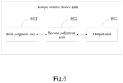
- FIG. 6 is a structural block diagram of the torque control device 600 provided by the embodiment of the invention, the device 600 including a first judgment unit 601, a second judgment unit 602, and an output unit 603:
- the first shut-off signal is generated by the steps of:
- the second shut-off signal is generated by the steps of:
- the torque deviation threshold is determined according to electric vehicle parameters corresponding to the target vehicle.
- the device 600 further includes a third judgment unit, a fourth judgment unit, and a conversion unit:
- the first short circuit signal is generated by the steps of:
- the second short circuit signal is generated by the steps of:
- the motor rotation speed threshold is determined according to motor parameters of the target vehicle.
- the first shut-off signal includes: any one or a combination of the first logic shut-off signal, the first buffer shut-off signal, and the first drive shut-off signal.
- the second shut-off signal includes: any one or a combination of the second logic shut-off signal, the second buffer shut-off signal, and the second drive shut-off signal.
- the output unit 603 is specifically configured such that:
- ROM read-only memory
- RAM random access memory
- magnetic disk magnetic disk
- optical disk magnetic tape
Landscapes
- Engineering & Computer Science (AREA)
- Power Engineering (AREA)
- Transportation (AREA)
- Mechanical Engineering (AREA)
- Life Sciences & Earth Sciences (AREA)
- Sustainable Development (AREA)
- Sustainable Energy (AREA)
- Electric Propulsion And Braking For Vehicles (AREA)
- Safety Devices In Control Systems (AREA)
Abstract
Description
- The invention relates to the field of automobile safety technologies, and in particular to a torque control method for controlling driving torque of an electric vehicle and a related device.
- With the development of automobile technologies, safety in driving an automobile has become one of important concerns for people who drive the automobile. Driving torque is an important factor that affects the driving of the automobile, and whether the torque can be safely controlled or not directly affects the safety of the automobile.
- In the related art, the driving torque is adjusted by a torque controller in an electric vehicle. This results in a lower fault tolerance rate and a poor safety of torque control.
- In order to solve the above technical problems, the invention provides a torque control method for controlling driving torque of an electric vehicle in which a processing device can judge whether a shut-off signal sent by a first or second torque controller is obtained respectively so that a redundant system is formed by the two torque controllers, thereby avoiding that the torque cannot be accurately controlled due to the damage of one torque controller and improving the safety and reliability of the torque control.
- Embodiments of the invention disclose the following technical solutions.
- In a first aspect, the embodiments of the invention provide a torque control method for controlling driving torque of an electric vehicle including the steps of:
- performing a first judgment to judge whether a first shut-off signal sent by a first torque controller is obtained;
- performing a second judgment to judge whether a second shut-off signal sent by a second torque controller is obtained; and
- outputting a first stop signal to stop outputting a torque if the judgment result of at least one of the first judgment and the second judgment is yes.
- Optionally, the first shut-off signal is generated by the steps of:
- judging whether the absolute value of an actual torque value of a target vehicle is not less than the absolute value of a torque abnormality threshold by the first torque controller, wherein the torque abnormality threshold is determined according to a torque request value and a torque deviation threshold; and
- generating and sending out the first shut-off signal by the first torque controller if the absolute value of the actual torque value is not less than the absolute value of the torque abnormality threshold; and
- the second shut-off signal is generated by the steps of:
- judging whether the absolute value of the actual torque value is not less than the absolute value of the torque abnormality threshold by the second torque controller; and
- generating and sending out the second shut-off signal by the second torque controller if the absolute value of the actual torque value is not less than the absolute value of the torque abnormality threshold.
- Optionally, the torque deviation threshold is determined according to electric vehicle parameters corresponding to the target vehicle.
- Optionally, the method further includes, before performing the first judgment, the steps of:
- performing a third judgment to judge whether a first short circuit signal sent by the first torque controller is obtained;
- performing a fourth judgment to judge whether a second short circuit signal sent by the second torque controller is obtained; and
- converting the first stop signal into a second stop signal to shut off electric vehicle power of the target vehicle if the judgment result of at least one of the third judgment and the fourth judgment is yes.
- Optionally, the first short circuit signal is generated by the steps of:
- judging whether the absolute value of an electric motor rotation speed of the target vehicle is not less than the absolute value of an electric motor rotation speed threshold by the first torque controller; and
- generating the first short circuit signal if the absolute value of the motor rotation speed is not less than the absolute value of the motor rotation speed threshold; and
- the second short circuit signal is generated by the steps of:
- judging whether the absolute value of the motor rotation speed is not less than the absolute value of the motor rotation speed threshold by the second torque controller; and
- generating the second short circuit signal if the absolute value of the motor rotation speed is not less than the absolute value of the motor rotation speed threshold.
- Optionally, the motor rotation speed threshold is determined according to motor parameters of the target vehicle.
- Optionally, the first shut-off signal comprises:
- any one or a combination of a first logic shut-off signal, a first buffer shut-off signal, and a first drive shut-off signal; and
- the second shut-off signal comprises:
any one or a combination of a second logic shut-off signal, a second buffer shut-off signal, and a second drive shut-off signal; - wherein outputting the first stop signal if the judgment result of the at least one of the first judgment and the second judgment is yes specifically includes:
the first stop signal including a logic stop signal to stop a logic device from outputting a torque pulse if the first logic shut-off signal or the second logic shut-off signal is obtained; - the first stop signal including a buffer stop signal to stop a buffer device from outputting the torque pulse if the first buffer shut-off signal or the second buffer shut-off signal is obtained;
- the first stop signal including a drive stop signal to stop a drive device from outputting the torque pulse if the first drive shut-off signal or the second drive shut-off signal is obtained.
- In a second aspect, the embodiments of the invention provide a torque control device for controlling driving torque of an electric vehicle comprising:
- a first judgment unit configured to perform a first judgment to judge whether a first shut-off signal sent by a first torque controller is obtained;
- a second judgment unit configured to perform a second judgment to judge whether a second shut-off signal sent by a second torque controller is obtained;
- an output unit configured to output a first stop signal to stop outputting a torque if the judgment result of at least one of the first judgment and the second judgment is yes.
- Optionally, the first shut-off signal is generated by the steps of:
- judging whether the absolute value of an actual torque value of a target vehicle is not less than the absolute value of a torque abnormality threshold by the first torque controller, wherein the torque abnormality threshold is determined according to a torque request value and a torque deviation threshold; and
- generating and sending out the first shut-off signal by the first torque controller if the absolute value of the actual torque value is not less than the absolute value of the torque abnormality threshold; and
- the second shut-off signal is generated by the steps of:
- judging whether the absolute value of the actual torque value is not less than the absolute value of the torque abnormality threshold by the second torque controller; and
- generating and sending out the second shut-off signal by the second torque controller if the absolute value of the actual torque value is not less than the absolute value of the torque abnormality threshold.
- Optionally, the torque deviation threshold is determined according to electric vehicle parameters corresponding to the target vehicle.
- It can be seen from the above technical solutions that the invention provides the torque control method in which the processing device can judge whether the first shut-off signal sent by the first torque controller or the second shut-off signal sent by the second torque controller is obtained respectively. If the processing device judges that at least one of the signals has been obtained, then outputs the first stop signal to stop outputting the torque. The processing device can receive the signals of the first and second torque controllers so that a redundant system is formed between the two torque controllers. If either one of the controllers is damaged, the processing device can still perform the torque control by means of the other controller, thereby improving the safety of the torque control and reducing the probability of risks in the process of driving a vehicle.
- In order to illustrate the technical solutions in embodiments of the invention or the prior art more clearly, the drawings required to be used for the embodiments or the prior art will be briefly described now. Obviously, the drawings described now only represent some embodiments of the invention. For those of ordinary skill in the art, other embodiments can be conceived based on these drawings without creative work.
-
FIG. 1 is a flowchart of a torque control method for controlling driving torque of an electric vehicle provided by an embodiment of the invention; -
FIG. 2 is a schematic diagram of a torque control method for controlling driving torque of an electric vehicle in an actual application scenario provided by an embodiment of the invention; -
FIG. 3 is a schematic diagram of a torque control method for controlling driving torque of an electric vehicle in an actual application scenario provided by an embodiment of the invention; -
FIG. 4 is a schematic diagram of a torque control method for controlling driving torque of an electric vehicle in an actual application scenario provided by an embodiment of the invention; -
FIG. 5 is a schematic diagram of a torque control method for controlling driving torque of an electric vehicle in an actual application scenario provided by an embodiment of the invention; and -
FIG. 6 is a structural block diagram of a torque control device for controlling driving torque of an electric vehicle provided by an embodiment of the invention. - The embodiments of the invention will be described now with reference to the drawings.
- Driving torque control is one of important factors related to safety in driving an automobile. If the torque control fails, the automobile may encounter a series of problems, such as the speed of the automobile is unable to be adjusted or the automobile is unable to be controlled sensitively, seriously threatening the personal safety of users.
- In the related art, the driving torque control is performed by a torque controller in an electric vehicle. There is only one torque controller in one vehicle. Thus, when the torque controller breaks down, it will become impossible to control the torque of the vehicle well. As a result, the safety of the vehicle deteriorates.
- In order to solve the above-mentioned technical problems, the invention provides a torque control method for controlling driving torque of an electric vehicle in which a processing device can judge whether a shut-off signal sent by a first or second torque controller is obtained respectively so that a redundant system is formed between the two torque controllers, thereby avoiding that the torque cannot be accurately controlled due to the damage of one torque controller and improving the safety and reliability of the torque control.
- It can be understood that the method can be applied by the processing device with a torque control function, such as a terminal device or a server. The method can be executed by the terminal device or the server separately, or can also be executed by a network scenario where the terminal device and the server communicate and cooperate with each other. The terminal device may be a computer or the like. The server can be understood as an application server or a web server. In an actual deployment, the server can be an independent server or a cluster server. While the technical solutions can be implemented in a hardware environment such as an ARM processor and an X86 processor, the technical solutions also can be implemented in a software environment such as an Android platform, Windows XP and above operation systems or a Linux operation system.
- The torque control method provided by the embodiments of the invention will be described now with reference to the drawings. Referring to
FIG. 1 which is a flowchart of a torque control method for controlling driving torque of an electric vehicle provided by an embodiment of the invention, the method includes:
S101: performing a first judgment. - In the process of driving an electric vehicle, a torque controller in the vehicle will send out various signals for torque control, among which, a shut-off signal to shut off a subsequent adjustment of the torque is sent out when the torque of the vehicle is abnormal, for example, when a present actual torque of the vehicle far exceeds a torque requested in the vehicle, in order to prevent a danger of driving the vehicle.
- In the embodiment of the invention, in order to achieve a redundant control of the torque, two torque controllers, e.g., two torque control chips, namely first and second torque controllers, may be provided in a target vehicle. The two torque controllers can monitor and analyze driving conditions of the target vehicle and determine whether the present torque of the target vehicle is abnormal. Multiple ways may be used by the torque controllers to judge whether the torque is abnormal. In a possible implemented way, the torque controllers may determine the actual torque of the target vehicle by means of a three-phase current and a rotor position corresponding to the target vehicle.
- When an abnormal torque occurs but the first and second torque controllers can operate properly, the first and second torque controllers both can send the shut-off signal to a processing device. The processing device may perform a first judgment to judge whether a first shut-off signal sent by the first torque controller is obtained.
- S102: performing a second judgment.
- In order to avoid that the torque can't be effectively controlled due to a failure of the first torque controller, the processing device may further perform a second judgment to judge whether a second shut-off signal sent by the second torque controller is obtained.
- S103: outputting a first stop signal if the judgment result of at least one of the first judgment and the second judgment is yes.
- In order to achieve the redundant control of the torque, after the processing device performs the first judgment and the second judgment and as long as one of judgment results is yes, it means that the shut-off signal sent by the first or second torque controller has been obtained. It proves that the torque of the target vehicle is abnormal. Thus, in order to prevent the abnormal torque from causing harm to the process of driving the vehicle, the processing device may output the first stop signal to stop outputting a torque.
- It can be seen from the above technical solutions that the invention provides the torque control method in which the processing device can judge whether the first shut-off signal sent by the first torque controller or the second shut-off signal sent by the second torque controller is obtained respectively. If the processing device judges that the at least one of the signals has been obtained, then outputs the first stop signal to stop outputting the torque. The processing device can receive the signals of the first and second torque controllers so that a redundant system is formed between the two torque controllers. If either one of the controllers is damaged, the processing device can still perform the torque control by means of the other controller, thereby improving the safety of the torque control and reducing the probability of risks in the process of driving the vehicle.
- It can be understood that there are multiple ways to judge whether the torque is abnormal. In a possible implemented way, the first shut-off signal may be generated by the steps of judging whether the absolute value of an actual torque value of the target vehicle is not less than the absolute value of a torque abnormality threshold by the first torque controller. The torque abnormality threshold is a threshold for identifying that the torque of the vehicle is in an abnormal state, and the torque abnormality threshold can be determined according to a torque request value and a torque deviation threshold. The torque request value refers to a torque value actually requested in the target vehicle when performing the torque control and the torque deviation threshold refers to a maximum value that the actual torque of the target vehicle can be deviated from the torque request value in a normal condition.
- If the absolute value of the actual torque value is not less than the absolute value of the torque abnormality threshold, it means that the actual torque value of the target vehicle has reached the maximum value that can be deviated in the normal condition, and it can be judged that the torque of the target vehicle is in an abnormal state. The first torque controller may generate and send out the first shut-off signal.
- Similarly, the second shut-off signal can be generated by the steps of: judging whether the absolute value of the actual torque value is not less than the absolute value of the torque abnormality threshold by the second torque controller; and generating and sending out the second shut-off signal by the second torque controller if the absolute value of the actual torque value is not less than the absolute value of the torque abnormality threshold.
- Because structures and performances, e.g., electric motor models, of different electric vehicles may be different, each vehicle can have a different allowable torque deviation value. In a possible implemented way, the processing device may determine the torque deviation threshold according to electric vehicle parameters corresponding to the target vehicle in order to improve the accuracy of the torque control.
- It is understood that the processing device may monitor an electric motor rotation speed of the target vehicle in addition to the torque value when performing the torque control in order to further improve the safety of the vehicle. When the torque control is performed, a sudden stop of outputting the torque may bring certain risks to the vehicle if the present vehicle is at a high speed. Thus, in a possible implemented way, the processing device can judge a present speed of the target vehicle when performing the torque control.
- Similarly, the processing device can judge the vehicle speed in a redundant way in order to improve a fault tolerance rate of the judgment. The processing device can perform a third judgment to judge whether a first short circuit signal sent by the first torque controller is obtained and a fourth judgment to judge whether a second short circuit signal sent by the second torque controller is obtained. The first and second short circuit signals are both used to identify that the present vehicle speed is in an excessively high state so that electric vehicle power is required to be short circuited to decrease the vehicle speed to a stable state. Thus, if the judgment result of at least one of the third judgment and the fourth judgment is yes, it means that the vehicle speed is required to be controlled and the processing device can convert the first stop signal into a second stop signal to shut off the vehicle power of the target vehicle. Thus, when the vehicle speed is too high, the processing device can avoid directly adjusting the torque, but indirectly realize the torque control by controlling the vehicle speed.
- The torque controller can judge the vehicle speed in multiple ways. In a possible implemented way, since driving the vehicle is realized by rotating an electric motor, the speed of the target vehicle can be determined by the motor rotation speed. The first short circuit signal is generated by the steps of: judging whether the absolute value of the motor rotation speed of the target vehicle is not less than the absolute value of an electric motor rotation speed threshold by the first torque controller. If the absolute value of the motor rotation speed is not less than the absolute value of the motor rotation speed threshold, it means that the motor rotation speed is too high so that the first short circuit signal can be generated. Similarly, in order to achieve the redundant control, the second torque controller can also judge whether the absolute value of the motor rotation speed is not less than the absolute value of the motor rotation speed threshold. If the absolute value of the motor rotation speed is not less than the absolute value of the motor rotation speed threshold, the second torque controller can generate the second short circuit signal.
- It is understood that because electric motor models of different electric vehicles can be different, motor rotation speed thresholds corresponding to the different vehicles can be different. In order to improve the accuracy of the torque control method, the processing device may determine the motor rotation speed threshold according to electric motor parameters of the target vehicle.
- In addition, in order to be able to control torque parameters finely, the processing device can analyze torque control architecture of the vehicle, so as to output the shut-off signal in a targeted manner. For example, the vehicle torque control architecture may include a logic device, a buffer device, and a drive device. These three devices are connected with each other in a linear manner and output the torque by transmitting a torque pulse. If the pulse transmission of any one of the devices is shut off, outputting the torque will be stopped. Thus, in order to further improve a success rate of the torque control, the processing device can control these three devices separately.
- In a possible implemented way, the above-mentioned first shut-off signal may comprise any one or a combination of a first logic shut-off signal, a first buffer shut-off signal, and a first drive shut-off signal, and the second The shut-off signal may comprise any one or a combination of a second logical shut-off signal, a second buffer shut-off signal, and a second drive shut-off signal. If the processing device obtains the first or second logical shut-off signal, the outputted first stop signal may include a logical stop signal to stop the logic device from outputting the torque pulse. If the processing device obtains the first or second buffer shut-off signal, the outputted first stop signal may include a buffer stop signal to stop the buffer device from outputting the torque pulse. If the first drive shut-off signal obtains the first or second drive shut-off signal, the outputted first stop signal may include a drive stop signal to stop the drive device from outputting the torque pulse.
- The torque control method in an actual application scenario provided by an embodiment of the invention will be described now. Refer to
FIG. 2 which is a schematic diagram of the torque control method in the actual application scenario provided by the embodiment of the invention. In the actual application scenario, the processing device is an electric motor controller to control the torque of the vehicle. - The motor controller has a main control chip and an auxiliary control chip, and the auxiliary control chip is configured to provide a redundant control function to the torque control. In the process of adjusting the torque, the motor controller can first receive a torque request and adjust the torque of the vehicle according to the torque request. Both of the main and auxiliary control chips can receive a rotor position signal sent by a rotor position sensor and a three-phase current signal sent by a current sensor, and can determine an actual torque of an electric motor according to the signals. In the meanwhile, the main and auxiliary control chips can analyze the rotor position to determine the present motor rotation speed.
- Upon determining the actual torque and the motor rotation speed, the main and auxiliary control chips can judge whether to send a signal based on this information. The judgment process is set forth as below.
- The main and auxiliary control chips determine whether the absolute value of the actual torque is not less than the absolute value of the torque abnormality threshold according to the determined actual torque and whether the absolute value of the motor rotation speed is not less than the absolute value of the motor rotation speed threshold. Taking the main control chip as an example, the judgment process of the main control chip is shown in
FIG. 3 :
The main control chip first determines whether the absolute value of the actual torque of the motor is not less than the absolute value of the torque abnormality threshold, and then determines whether the absolute value of the motor rotation speed is not less than the absolute value of the motor rotation speed threshold if the absolute value of the actual torque is not less than the absolute value of the torque abnormality threshold. If the absolute value of the motor rotation speed is not less than the absolute value of the motor rotation speed threshold, the first short circuit signal is directly outputted. If the absolute value of the motor rotation speed is less than the absolute value of the motor rotation speed threshold, the first logic shut-off signal, the first buffer shut-off signal and the first drive shut-off signal are outputted. - A specific judgment result is set forth in the following formula:

FIG. 4 . Thus, the main control chip outputs the first short circuit signal.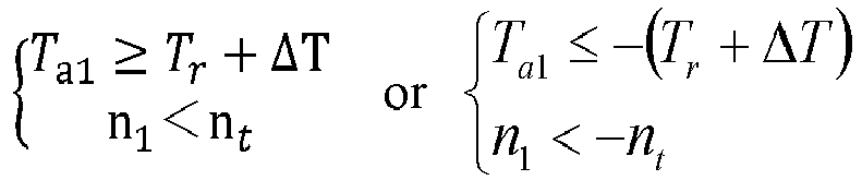
- In the above case, the absolute value of the actual torque is not less than the absolute value of the torque abnormality threshold, and the absolute value of the motor rotation speed is less than the absolute value of the motor rotation speed threshold. The judgment result is in areas marked by 2, 3, 6 and 7 in the result distribution diagram shown in
FIG. 4 , so the main control chip outputs the first logic shut-off signal, the first buffer shut-off signal and the first drive shut-off signal. - Similarly, the judgment logic of the auxiliary control chip is shown in
FIG. 5 . Different from the main control chip, the auxiliary control chip outputs the second short circuit signal, the second logic shut-off signal, the second buffer shut-off signal and the second drive shut-off signal. The judgment result of the auxiliary control chip is shown in the following formula:
FIG. 4 . Thus, the auxiliary control chip outputs the second short circuit signal.
- In the above case, the absolute value of the actual torque is not less than the absolute value of the torque abnormality threshold, and the absolute value of the motor rotation speed is less than the absolute value of the motor rotation speed threshold. The judgment result is in areas marked by 2, 3, 6 and 7 in the result distribution diagram shown in
FIG. 4 , so the auxiliary control chip outputs the second logic shut-off signal, the second buffer shut-off signal and the second drive shut-off signal. - An active short circuit drive circuit in the motor controller can determine whether the first or second short circuit signal is received. If either one of the first or second short circuit signal is received, lower three bridges of a power module are all driven to be closed and upper three bridges of the power module are all driven to be opened, such that the vehicle power of the vehicle is shut off. If neither of the first or second short circuit signal is received, a first OR gate in the motor controller can judge whether the first or second logical shut-off signal is received, and a stop signal will be sent to the complex programmable logic device to stop it from sending a PWM pulse wave if either one of the first or second logical shut-off signal is received; a second OR gate can judge whether the first or second buffer shut-off signal is received, and the stop signal will be sent to the buffer device to stop it from sending the PWM pulse wave if either one of the first or second buffer shut-off signal is received; and a third OR gate can determine whether the first or second drive shut-off signal is received, and the stop signal will be sent to the drive device to stop it from sending the PWM pulse wave if either one of the first or second drive shut-off signal is received. Based on this, the motor controller can judge the first or second logical, buffer, and drive shut-off signals separately, further improving the reliability of the torque control.
- Based on the torque control method provided by the foregoing embodiments, a torque control device for controlling driving torque of an electric vehicle is provided by an embodiment of the invention. Refer to
FIG. 6 which is a structural block diagram of thetorque control device 600 provided by the embodiment of the invention, thedevice 600 including afirst judgment unit 601, a second judgment unit 602, and an output unit 603: - the
first judgment unit 601 is configured to perform a first judgment to judge whether a first shut-off signal sent by a first torque controller is obtained; - the second judgment unit 602 is configured to perform a second judgment to judge whether a second shut-off signal sent by a second torque controller is obtained; and
- the output unit 603 is configured to output a first stop signal to stop outputting a torque if the judgment result of at least one of the first judgment and the second judgment is yes.
- In a possible implemented way, the first shut-off signal is generated by the steps of:
- judging whether the absolute value of an actual torque value of a target vehicle is not less than the absolute value of a torque abnormality threshold by the first torque controller, wherein the torque abnormality threshold is determined according to a torque request value and a torque deviation threshold; and
- generating and sending out the first shut-off signal by the first torque controller if the absolute value of the actual torque value is not less than the absolute value of the torque abnormality threshold.
- The second shut-off signal is generated by the steps of:
- judging whether the absolute value of the actual torque value is not less than the absolute value of the torque abnormality threshold by the second torque controller; and
- generating and sending out the second shut-off signal by the second torque controller if the absolute value of the actual torque value is not less than the absolute value of the torque abnormality threshold.
- In a possible implemented way, the torque deviation threshold is determined according to electric vehicle parameters corresponding to the target vehicle.
- In a possible implemented way, the
device 600 further includes a third judgment unit, a fourth judgment unit, and a conversion unit: - the third judgment unit is configured to perform a third judgment to judge whether a first short circuit signal sent by the first torque controller is obtained;
- the fourth judgment unit is configured to perform a fourth judgment to judge whether a second short circuit signal sent by the second torque controller is obtained; and
- the conversion unit is configured to convert the first stop signal into a second stop signal to shut off vehicle power of the target vehicle if the judgment result of at least one of the third judgment and the fourth judgment is yes.
- In a possible implemented way, the first short circuit signal is generated by the steps of:
- judging whether the absolute value of an electric motor rotation speed of the target vehicle is not less than the absolute value of an electric motor rotation speed threshold by the first torque controller; and
- generating the first short circuit signal if the absolute value of the motor rotation speed is not less than the absolute value of the motor rotation speed threshold.
- The second short circuit signal is generated by the steps of:
- judging whether the absolute value of the motor rotation speed is not less than the absolute value of the motor rotation speed threshold by the second torque controller;
- generating the second short circuit signal if the absolute value of the motor rotation speed is not less than the absolute value of the motor rotation speed threshold.
- In a possible implementation, the motor rotation speed threshold is determined according to motor parameters of the target vehicle.
- In a possible implemented way, the first shut-off signal includes:
any one or a combination of the first logic shut-off signal, the first buffer shut-off signal, and the first drive shut-off signal. - The second shut-off signal includes:
any one or a combination of the second logic shut-off signal, the second buffer shut-off signal, and the second drive shut-off signal. - The output unit 603 is specifically configured such that:
- if the first or second logic off signal is obtained, the first stop signal comprises a logic stop signal to stop a logic device from outputting a torque pulse;
- if the first or second buffer shut-off signal is obtained, the first stop signal comprises a buffer stop signal to stop a buffer device from outputting the torque pulse; and
- if the first or second drive shut-off signal is obtained, the first stop signal comprises a drive stop signal to stop a drive device from outputting the torque pulse.
- Those of ordinary skill in the art can understand that all or part of the steps in the above method of the embodiments can be implemented by a hardware associated with program instructions stored in a computer readable storage medium. The steps of the above method of the embodiments are performed when the instructions are executed. The foregoing storage medium can be at least one of the following media: read-only memory (ROM), RAM, a magnetic disk, an optical disk, or a medium that can store program codes.
- It should be noted that the various embodiments in the specification are described in a progressive manner, so the same or similar parts of the various embodiments can refer to each other, and each embodiment is illustrated mainly for its difference from the other embodiments. In particular, since the device and system embodiments are basically similar to the method embodiments, the related parts of the device and system embodiments are simply described and can be refer to those of the method embodiments. The above-described device and system embodiments are only illustrative. A unit described as a separate component may or may not be physically separated, and components shown as a unit may or may not form a physical unit, that is, the components may be located in one place or distributed in multiple network elements. Some or all of modules may be selected according to an actual need to achieve an objective of the technical solutions of the embodiments. Those of ordinary skill in the art can understand and implement them without creative work.
- The above is only a specific embodiment of the invention, but the protection scope of the invention is not limited to this. Any person skilled in the art can easily conceive of changes or replacements within the technical scope disclosed in the invention and the changes or replacements shall be covered within the protection scope of the invention. Thus, the protection scope of the invention should be subject to the claims.
Claims (10)
- A torque control method for controlling driving torque of an electric vehicle, characterized in that the method includes the steps of:performing a first judgment to judge whether a first shut-off signal sent by a first torque controller is obtained;performing a second judgment to judge whether a second shut-off signal sent by a second torque controller is obtained; andoutputting a first stop signal to stop outputting a torque if the judgment result of at least one of the first judgment and the second judgment is yes.
- The method of claim 1, characterized in that the first shut-off signal is generated by the steps of:judging whether the absolute value of an actual torque value of a target vehicle is not less than the absolute value of an torque abnormality threshold by the first torque controller, wherein the torque abnormality threshold is determined according to a torque request value and a torque deviation threshold; andgenerating and sending out the first shut-off signal by the first torque controller if the absolute value of the actual torque value is not less than the absolute value of the torque abnormality threshold; andthe second shut-off signal is generated by the steps of:judging whether the absolute value of the actual torque value is not less than the absolute value of the torque abnormality threshold by the second torque controller; andgenerating and sending out the second shut-off signal by the second torque controller if the absolute value of the actual torque value is not less than the absolute value of the torque abnormality threshold.
- The method of claim 2, characterized in that the torque deviation threshold is determined according to electric vehicle parameters corresponding to the target vehicle.
- The method according to claim 1, characterized in that the method further includes, before performing the first judgment, the steps of:performing a third judgment to judge whether a first short circuit signal sent by the first torque controller is obtained;performing a fourth judgment to judge whether a second short circuit signal sent by the second torque controller is obtained; andconverting the first stop signal into a second stop signal to shut off electric vehicle power of the target vehicle if the judgment result of at least one of the third judgment and the fourth judgment is yes.
- The method of claim 4, characterized in that the first short circuit signal is generated by the steps of:judging whether the absolute value of an electric motor rotation speed of the target vehicle is not less than the absolute value of an electric motor rotation speed threshold by the first torque controller; andgenerating the first short circuit signal if the absolute value of the motor rotation speed is not less than the absolute value of the motor rotation speed threshold; andthe second short circuit signal is generated by the steps of:judging whether the absolute value of the motor rotation speed is not less than the absolute value of the motor rotation speed threshold by the second torque controller; andgenerating the second short circuit signal if the absolute value of the motor rotation speed is not less than the absolute value of the motor rotation speed threshold.
- The method of claim 5, characterized in that the motor rotation speed threshold is determined according to electric motor parameters of the target vehicle.
- The method of claim 1, characterized in that the first shut-off signal comprises:any one or a combination of a first logic shut-off signal, a first buffer shut-off signal, and a first drive shut-off signal; andthe second shut-off signal comprises:
any one or a combination of a second logic shut-off signal, a second buffer shut-off signal, and a second drive shut-off signal;wherein outputting the first stop signal if the judgment result of the at least one of the first judgment and the second judgment is yes specifically includes:the first stop signal including a logic stop signal to stop a logic device from outputting a torque pulse if the first logic shut-off signal or the second logic shut-off signal is obtained;the first stop signal including a buffer stop signal to stop a buffer device from outputting the torque pulse if the first buffer shut-off signal or the second buffer shut-off signal is obtained;the first stop signal including a drive stop signal to stop a drive device from outputting the torque pulse if the first drive shut-off signal or the second drive shut-off signal is obtained. - A torque control device for controlling driving torque of an electric vehicle, characterized in that the device comprises:a first judgment unit configured to perform a first judgment to judge whether a first shut-off signal sent by a first torque controller is obtained;a second judgment unit configured to perform a second judgment to judge whether a second shut-off signal sent by a second torque controller is obtained;an output unit configured to output a first stop signal to stop outputting a torque if the judgment result of at least one of the first judgment and the second judgment is yes.
- The device of claim 8, characterized in that the first shut-off signal is generated by the steps of:judging whether the absolute value of an actual torque value of a target vehicle is not less than the absolute value of a torque abnormality threshold by the first torque controller, wherein the torque abnormality threshold is determined according to a torque request value and a torque deviation threshold; andgenerating and sending out the first shut-off signal by the first torque controller if the absolute value of the actual torque value is not less than the absolute value of the torque abnormality threshold; andthe second shut-off signal is generated by the steps of:judging whether the absolute value of the actual torque value is not less than the absolute value of the torque abnormality threshold by the second torque controller; andgenerating and sending out the second shut-off signal by the second torque controller if the absolute value of the actual torque value is not less than the absolute value of the torque abnormality threshold.
- The device of claim 9, characterized in that the torque deviation threshold is determined according to electric vehicle parameters corresponding to the target vehicle.
Applications Claiming Priority (1)
| Application Number | Priority Date | Filing Date | Title |
|---|---|---|---|
| CN202010744643.2A CN114056108B (en) | 2020-07-29 | 2020-07-29 | A torque control method and related devices |
Publications (2)
| Publication Number | Publication Date |
|---|---|
| EP3944979A1 true EP3944979A1 (en) | 2022-02-02 |
| EP3944979B1 EP3944979B1 (en) | 2025-07-16 |
Family
ID=73543115
Family Applications (1)
| Application Number | Title | Priority Date | Filing Date |
|---|---|---|---|
| EP20208911.6A Active EP3944979B1 (en) | 2020-07-29 | 2020-11-20 | Torque control method for controlling driving torque of an electric vehicle and related device |
Country Status (2)
| Country | Link |
|---|---|
| EP (1) | EP3944979B1 (en) |
| CN (1) | CN114056108B (en) |
Cited By (2)
| Publication number | Priority date | Publication date | Assignee | Title |
|---|---|---|---|---|
| CN116160868A (en) * | 2023-02-03 | 2023-05-26 | 岚图汽车科技有限公司 | Energy management control method for assisting torque runaway and related equipment |
| WO2024022132A1 (en) * | 2022-07-29 | 2024-02-01 | 武汉路特斯汽车有限公司 | Control method, apparatus and system for electric vehicle door, and vehicle |
Citations (3)
| Publication number | Priority date | Publication date | Assignee | Title |
|---|---|---|---|---|
| EP3040233A1 (en) * | 2013-08-30 | 2016-07-06 | Hitachi Automotive Systems, Ltd. | Electric vehicle control system |
| US20170066326A1 (en) * | 2014-02-18 | 2017-03-09 | Jaguar Land Rover Limited | Control system and method |
| JP2018125958A (en) * | 2017-01-31 | 2018-08-09 | 株式会社デンソー | Control device for pole switching motor |
Family Cites Families (4)
| Publication number | Priority date | Publication date | Assignee | Title |
|---|---|---|---|---|
| BR112017007612A2 (en) * | 2014-10-17 | 2018-06-19 | Nsk Ltd | electric power steering |
| DE102018114828B3 (en) * | 2018-06-20 | 2019-07-25 | Thyssenkrupp Ag | Motor vehicle steering with a redundantly designed control unit |
| JP7514599B2 (en) * | 2018-12-21 | 2024-07-11 | 株式会社ジェイテクト | Steering System |
| CN109774721B (en) * | 2019-02-28 | 2021-08-20 | 国机智骏汽车有限公司 | Speed closed-loop control system, method and electric vehicle |
-
2020
- 2020-07-29 CN CN202010744643.2A patent/CN114056108B/en not_active Expired - Fee Related
- 2020-11-20 EP EP20208911.6A patent/EP3944979B1/en active Active
Patent Citations (3)
| Publication number | Priority date | Publication date | Assignee | Title |
|---|---|---|---|---|
| EP3040233A1 (en) * | 2013-08-30 | 2016-07-06 | Hitachi Automotive Systems, Ltd. | Electric vehicle control system |
| US20170066326A1 (en) * | 2014-02-18 | 2017-03-09 | Jaguar Land Rover Limited | Control system and method |
| JP2018125958A (en) * | 2017-01-31 | 2018-08-09 | 株式会社デンソー | Control device for pole switching motor |
Cited By (2)
| Publication number | Priority date | Publication date | Assignee | Title |
|---|---|---|---|---|
| WO2024022132A1 (en) * | 2022-07-29 | 2024-02-01 | 武汉路特斯汽车有限公司 | Control method, apparatus and system for electric vehicle door, and vehicle |
| CN116160868A (en) * | 2023-02-03 | 2023-05-26 | 岚图汽车科技有限公司 | Energy management control method for assisting torque runaway and related equipment |
Also Published As
| Publication number | Publication date |
|---|---|
| CN114056108B (en) | 2024-02-13 |
| CN114056108A (en) | 2022-02-18 |
| EP3944979B1 (en) | 2025-07-16 |
Similar Documents
| Publication | Publication Date | Title |
|---|---|---|
| EP2701301B1 (en) | Motor driving system | |
| CN114851859B (en) | A system and method for safely monitoring output torque of an electric drive system | |
| KR102791256B1 (en) | Apparatus and method for controlling sudden unintended acceleration of vehicle | |
| EP3944979B1 (en) | Torque control method for controlling driving torque of an electric vehicle and related device | |
| CN108016297A (en) | Fault handling method, motor driven systems and the vehicle of motor driven systems | |
| CN113968237B (en) | An unmanned vehicle steering system, operation method and storage device | |
| CN108215935A (en) | Automobile max. speed management method, device, storage medium and electric vehicle | |
| CN114347803A (en) | New energy vehicle torque safety monitoring and processing method | |
| CN110932235A (en) | A protection method and device for a multi-motor cluster system | |
| WO2025201530A1 (en) | Autonomous driving torque verification method, autonomous driving monitoring system, vehicle and medium | |
| CN115723575A (en) | Torque control method, device, equipment and storage medium | |
| KR102098048B1 (en) | Apparatus and method for controlling vehicle based on redundant architecture | |
| CN117818357A (en) | Motor controller fault recovery method, device, equipment and storage medium | |
| CN112298223B (en) | Safe train control system | |
| CN111413860B (en) | A controller fault protection circuit, method and device | |
| CN111993902A (en) | Out-of-control treatment method and system for hydrogen fuel automobile driving motor | |
| JP3893744B2 (en) | Electric vehicle control device | |
| CN114531071B (en) | Motor control method, device, equipment, medium and vehicle | |
| CN117360233A (en) | High-voltage power-on system, method, medium, equipment and vehicle | |
| EP4656475A1 (en) | Driving system control method, driving system, apparatus, medium, and vehicle | |
| JP2024180115A (en) | Vehicle control device and vehicle control program | |
| WO2025253704A1 (en) | Protection device, drive system, protection method, program, main control device, and inverter control device | |
| WO2025253792A1 (en) | Protection device, drive system, protection method, and program | |
| KR102529984B1 (en) | Vehicle controller | |
| CN112848886B (en) | Accelerator pedal device, vehicle speed control method and hydrogen energy vehicle |
Legal Events
| Date | Code | Title | Description |
|---|---|---|---|
| PUAI | Public reference made under article 153(3) epc to a published international application that has entered the european phase |
Free format text: ORIGINAL CODE: 0009012 |
|
| STAA | Information on the status of an ep patent application or granted ep patent |
Free format text: STATUS: THE APPLICATION HAS BEEN PUBLISHED |
|
| AK | Designated contracting states |
Kind code of ref document: A1 Designated state(s): AL AT BE BG CH CY CZ DE DK EE ES FI FR GB GR HR HU IE IS IT LI LT LU LV MC MK MT NL NO PL PT RO RS SE SI SK SM TR |
|
| STAA | Information on the status of an ep patent application or granted ep patent |
Free format text: STATUS: REQUEST FOR EXAMINATION WAS MADE |
|
| 17P | Request for examination filed |
Effective date: 20220801 |
|
| RBV | Designated contracting states (corrected) |
Designated state(s): AL AT BE BG CH CY CZ DE DK EE ES FI FR GB GR HR HU IE IS IT LI LT LU LV MC MK MT NL NO PL PT RO RS SE SI SK SM TR |
|
| GRAP | Despatch of communication of intention to grant a patent |
Free format text: ORIGINAL CODE: EPIDOSNIGR1 |
|
| STAA | Information on the status of an ep patent application or granted ep patent |
Free format text: STATUS: GRANT OF PATENT IS INTENDED |
|
| INTG | Intention to grant announced |
Effective date: 20241118 |
|
| GRAJ | Information related to disapproval of communication of intention to grant by the applicant or resumption of examination proceedings by the epo deleted |
Free format text: ORIGINAL CODE: EPIDOSDIGR1 |
|
| STAA | Information on the status of an ep patent application or granted ep patent |
Free format text: STATUS: REQUEST FOR EXAMINATION WAS MADE |
|
| GRAP | Despatch of communication of intention to grant a patent |
Free format text: ORIGINAL CODE: EPIDOSNIGR1 |
|
| STAA | Information on the status of an ep patent application or granted ep patent |
Free format text: STATUS: GRANT OF PATENT IS INTENDED |
|
| INTC | Intention to grant announced (deleted) | ||
| INTG | Intention to grant announced |
Effective date: 20250217 |
|
| RIN1 | Information on inventor provided before grant (corrected) |
Inventor name: WANG, HUAN Inventor name: WU, QIANG Inventor name: XIE, MOYU Inventor name: JIANG, YANYAN Inventor name: SUN, XILIANG Inventor name: ZHANG, QIANG Inventor name: WEI, YU Inventor name: CAO, BIN Inventor name: GU, MENGJUN Inventor name: ZHU, JIANWEI Inventor name: XIE, JIAYUE Inventor name: PENG, BO |
|
| GRAS | Grant fee paid |
Free format text: ORIGINAL CODE: EPIDOSNIGR3 |
|
| GRAA | (expected) grant |
Free format text: ORIGINAL CODE: 0009210 |
|
| STAA | Information on the status of an ep patent application or granted ep patent |
Free format text: STATUS: THE PATENT HAS BEEN GRANTED |
|
| AK | Designated contracting states |
Kind code of ref document: B1 Designated state(s): AL AT BE BG CH CY CZ DE DK EE ES FI FR GB GR HR HU IE IS IT LI LT LU LV MC MK MT NL NO PL PT RO RS SE SI SK SM TR |
|
| REG | Reference to a national code |
Ref country code: GB Ref legal event code: FG4D |
|
| REG | Reference to a national code |
Ref country code: CH Ref legal event code: EP |
|
| REG | Reference to a national code |
Ref country code: DE Ref legal event code: R096 Ref document number: 602020054524 Country of ref document: DE |
|
| REG | Reference to a national code |
Ref country code: IE Ref legal event code: FG4D |
|
| REG | Reference to a national code |
Ref country code: NL Ref legal event code: MP Effective date: 20250716 |
|
| PG25 | Lapsed in a contracting state [announced via postgrant information from national office to epo] |
Ref country code: PT Free format text: LAPSE BECAUSE OF FAILURE TO SUBMIT A TRANSLATION OF THE DESCRIPTION OR TO PAY THE FEE WITHIN THE PRESCRIBED TIME-LIMIT Effective date: 20251117 |
|
| PG25 | Lapsed in a contracting state [announced via postgrant information from national office to epo] |
Ref country code: NL Free format text: LAPSE BECAUSE OF FAILURE TO SUBMIT A TRANSLATION OF THE DESCRIPTION OR TO PAY THE FEE WITHIN THE PRESCRIBED TIME-LIMIT Effective date: 20250716 |
|
| REG | Reference to a national code |
Ref country code: AT Ref legal event code: MK05 Ref document number: 1813762 Country of ref document: AT Kind code of ref document: T Effective date: 20250716 |
|
| PG25 | Lapsed in a contracting state [announced via postgrant information from national office to epo] |
Ref country code: IS Free format text: LAPSE BECAUSE OF FAILURE TO SUBMIT A TRANSLATION OF THE DESCRIPTION OR TO PAY THE FEE WITHIN THE PRESCRIBED TIME-LIMIT Effective date: 20251116 |
|
| PGFP | Annual fee paid to national office [announced via postgrant information from national office to epo] |
Ref country code: GB Payment date: 20251020 Year of fee payment: 6 |
|
| PG25 | Lapsed in a contracting state [announced via postgrant information from national office to epo] |
Ref country code: NO Free format text: LAPSE BECAUSE OF FAILURE TO SUBMIT A TRANSLATION OF THE DESCRIPTION OR TO PAY THE FEE WITHIN THE PRESCRIBED TIME-LIMIT Effective date: 20251016 |
|
| REG | Reference to a national code |
Ref country code: LT Ref legal event code: MG9D |
|
| PG25 | Lapsed in a contracting state [announced via postgrant information from national office to epo] |
Ref country code: AT Free format text: LAPSE BECAUSE OF FAILURE TO SUBMIT A TRANSLATION OF THE DESCRIPTION OR TO PAY THE FEE WITHIN THE PRESCRIBED TIME-LIMIT Effective date: 20250716 |
|
| PG25 | Lapsed in a contracting state [announced via postgrant information from national office to epo] |
Ref country code: FI Free format text: LAPSE BECAUSE OF FAILURE TO SUBMIT A TRANSLATION OF THE DESCRIPTION OR TO PAY THE FEE WITHIN THE PRESCRIBED TIME-LIMIT Effective date: 20250716 |
|
| PG25 | Lapsed in a contracting state [announced via postgrant information from national office to epo] |
Ref country code: HR Free format text: LAPSE BECAUSE OF FAILURE TO SUBMIT A TRANSLATION OF THE DESCRIPTION OR TO PAY THE FEE WITHIN THE PRESCRIBED TIME-LIMIT Effective date: 20250716 |
|
| PG25 | Lapsed in a contracting state [announced via postgrant information from national office to epo] |
Ref country code: GR Free format text: LAPSE BECAUSE OF FAILURE TO SUBMIT A TRANSLATION OF THE DESCRIPTION OR TO PAY THE FEE WITHIN THE PRESCRIBED TIME-LIMIT Effective date: 20251017 |
|
| PG25 | Lapsed in a contracting state [announced via postgrant information from national office to epo] |
Ref country code: SE Free format text: LAPSE BECAUSE OF FAILURE TO SUBMIT A TRANSLATION OF THE DESCRIPTION OR TO PAY THE FEE WITHIN THE PRESCRIBED TIME-LIMIT Effective date: 20250716 |
|
| PG25 | Lapsed in a contracting state [announced via postgrant information from national office to epo] |
Ref country code: LV Free format text: LAPSE BECAUSE OF FAILURE TO SUBMIT A TRANSLATION OF THE DESCRIPTION OR TO PAY THE FEE WITHIN THE PRESCRIBED TIME-LIMIT Effective date: 20250716 |
|
| PG25 | Lapsed in a contracting state [announced via postgrant information from national office to epo] |
Ref country code: BG Free format text: LAPSE BECAUSE OF FAILURE TO SUBMIT A TRANSLATION OF THE DESCRIPTION OR TO PAY THE FEE WITHIN THE PRESCRIBED TIME-LIMIT Effective date: 20250716 Ref country code: PL Free format text: LAPSE BECAUSE OF FAILURE TO SUBMIT A TRANSLATION OF THE DESCRIPTION OR TO PAY THE FEE WITHIN THE PRESCRIBED TIME-LIMIT Effective date: 20250716 |
|
| PG25 | Lapsed in a contracting state [announced via postgrant information from national office to epo] |
Ref country code: RS Free format text: LAPSE BECAUSE OF FAILURE TO SUBMIT A TRANSLATION OF THE DESCRIPTION OR TO PAY THE FEE WITHIN THE PRESCRIBED TIME-LIMIT Effective date: 20251016 |
|
| PG25 | Lapsed in a contracting state [announced via postgrant information from national office to epo] |
Ref country code: ES Free format text: LAPSE BECAUSE OF FAILURE TO SUBMIT A TRANSLATION OF THE DESCRIPTION OR TO PAY THE FEE WITHIN THE PRESCRIBED TIME-LIMIT Effective date: 20250716 |
|
| PG25 | Lapsed in a contracting state [announced via postgrant information from national office to epo] |
Ref country code: RO Free format text: LAPSE BECAUSE OF FAILURE TO SUBMIT A TRANSLATION OF THE DESCRIPTION OR TO PAY THE FEE WITHIN THE PRESCRIBED TIME-LIMIT Effective date: 20250716 |
|
| PG25 | Lapsed in a contracting state [announced via postgrant information from national office to epo] |
Ref country code: SM Free format text: LAPSE BECAUSE OF FAILURE TO SUBMIT A TRANSLATION OF THE DESCRIPTION OR TO PAY THE FEE WITHIN THE PRESCRIBED TIME-LIMIT Effective date: 20250716 |
|
| PG25 | Lapsed in a contracting state [announced via postgrant information from national office to epo] |
Ref country code: DK Free format text: LAPSE BECAUSE OF FAILURE TO SUBMIT A TRANSLATION OF THE DESCRIPTION OR TO PAY THE FEE WITHIN THE PRESCRIBED TIME-LIMIT Effective date: 20250716 |
|
| PG25 | Lapsed in a contracting state [announced via postgrant information from national office to epo] |
Ref country code: IT Free format text: LAPSE BECAUSE OF FAILURE TO SUBMIT A TRANSLATION OF THE DESCRIPTION OR TO PAY THE FEE WITHIN THE PRESCRIBED TIME-LIMIT Effective date: 20250716 |
|
| PG25 | Lapsed in a contracting state [announced via postgrant information from national office to epo] |
Ref country code: CZ Free format text: LAPSE BECAUSE OF FAILURE TO SUBMIT A TRANSLATION OF THE DESCRIPTION OR TO PAY THE FEE WITHIN THE PRESCRIBED TIME-LIMIT Effective date: 20250716 |
|
| PG25 | Lapsed in a contracting state [announced via postgrant information from national office to epo] |
Ref country code: EE Free format text: LAPSE BECAUSE OF FAILURE TO SUBMIT A TRANSLATION OF THE DESCRIPTION OR TO PAY THE FEE WITHIN THE PRESCRIBED TIME-LIMIT Effective date: 20250716 Ref country code: SK Free format text: LAPSE BECAUSE OF FAILURE TO SUBMIT A TRANSLATION OF THE DESCRIPTION OR TO PAY THE FEE WITHIN THE PRESCRIBED TIME-LIMIT Effective date: 20250716 |