EP3944935A1 - Adapter for a razor system - Google Patents
Adapter for a razor system Download PDFInfo
- Publication number
- EP3944935A1 EP3944935A1 EP20187986.3A EP20187986A EP3944935A1 EP 3944935 A1 EP3944935 A1 EP 3944935A1 EP 20187986 A EP20187986 A EP 20187986A EP 3944935 A1 EP3944935 A1 EP 3944935A1
- Authority
- EP
- European Patent Office
- Prior art keywords
- adapter
- razor head
- razor
- elements
- handle
- Prior art date
- Legal status (The legal status is an assumption and is not a legal conclusion. Google has not performed a legal analysis and makes no representation as to the accuracy of the status listed.)
- Granted
Links
Images

Classifications
-
- B—PERFORMING OPERATIONS; TRANSPORTING
- B26—HAND CUTTING TOOLS; CUTTING; SEVERING
- B26B—HAND-HELD CUTTING TOOLS NOT OTHERWISE PROVIDED FOR
- B26B21/00—Razors of the open or knife type; Safety razors or other shaving implements of the planing type; Hair-trimming devices involving a razor-blade; Equipment therefor
- B26B21/08—Razors of the open or knife type; Safety razors or other shaving implements of the planing type; Hair-trimming devices involving a razor-blade; Equipment therefor involving changeable blades
- B26B21/14—Safety razors with one or more blades arranged transversely to the handle
-
- B—PERFORMING OPERATIONS; TRANSPORTING
- B26—HAND CUTTING TOOLS; CUTTING; SEVERING
- B26B—HAND-HELD CUTTING TOOLS NOT OTHERWISE PROVIDED FOR
- B26B21/00—Razors of the open or knife type; Safety razors or other shaving implements of the planing type; Hair-trimming devices involving a razor-blade; Equipment therefor
- B26B21/08—Razors of the open or knife type; Safety razors or other shaving implements of the planing type; Hair-trimming devices involving a razor-blade; Equipment therefor involving changeable blades
- B26B21/14—Safety razors with one or more blades arranged transversely to the handle
- B26B21/22—Safety razors with one or more blades arranged transversely to the handle involving several blades to be used simultaneously
- B26B21/222—Safety razors with one or more blades arranged transversely to the handle involving several blades to be used simultaneously with the blades moulded into, or attached to, a changeable unit
- B26B21/225—Safety razors with one or more blades arranged transversely to the handle involving several blades to be used simultaneously with the blades moulded into, or attached to, a changeable unit the changeable unit being resiliently mounted on the handle
-
- B—PERFORMING OPERATIONS; TRANSPORTING
- B26—HAND CUTTING TOOLS; CUTTING; SEVERING
- B26B—HAND-HELD CUTTING TOOLS NOT OTHERWISE PROVIDED FOR
- B26B21/00—Razors of the open or knife type; Safety razors or other shaving implements of the planing type; Hair-trimming devices involving a razor-blade; Equipment therefor
- B26B21/40—Details or accessories
- B26B21/4012—Housing details, e.g. for cartridges
-
- B—PERFORMING OPERATIONS; TRANSPORTING
- B26—HAND CUTTING TOOLS; CUTTING; SEVERING
- B26B—HAND-HELD CUTTING TOOLS NOT OTHERWISE PROVIDED FOR
- B26B21/00—Razors of the open or knife type; Safety razors or other shaving implements of the planing type; Hair-trimming devices involving a razor-blade; Equipment therefor
- B26B21/40—Details or accessories
- B26B21/52—Handles, e.g. tiltable, flexible
- B26B21/521—Connection details, e.g. connection to razor heads
Definitions
- the present disclosure relates to the field of razors, in particular to razors for wet shaving.
- Razors for wet shaving having a handle, a razor head and an adapter for connecting the razor head to the handle are known in the art, for example from EP 2 879 845 B1 .
- the object of the present disclosure is to provide razor head and an adapter ensuring a safe connection between the razor head and a handle, wherein the manufacturing and mounting is facilitated. It is another object of the present invention to achieve improved pivoting properties of the razor head relative to the handle.
- the present disclosure relates to a razor head and an adapter as defined in claim 1.
- the dependent claims depict advantageous embodiments of the present disclosure.
- the adapter is designed to be connected to the razor head and is designed to be connected to a handle, wherein the razor head can be rotated with respect to the adapter around a razor head axis.
- a razor head biasing member is at least partially arranged within the adapter. With that, the manufacturing and mounting procedure is facilitated.
- the razor head biasing member preferably comprises a compression spring element and a pusher element for pushing the razor head into a rest position.
- the compression spring is fully contained within the adapter, whereas the pusher element is only partially contained within the adapter.
- the rest position of the razor head can be defined as being a maximum rotational position of the razor head with respect to the adapter. The portion of the pusher element which protrudes from the adapter engages a portion of the razor head, when the razor head is mounted on the adapter.
- the razor head may be rotatable around the razor head axis which is perpendicular or substantially perpendicular to the centroidal axis of the handle extending along the handle by at least up to 20 degrees, when the handle is held stationary, in particular from 0 degrees up to 40 degrees (wherein 0 degrees corresponds to the rest position of the razor head, and 40 degrees corresponds to the fully pivoted position of the razor head).
- the compression spring of the razor head biasing member may be compressed when the razor head is rotated away from the rest position, in particular when a user moves the razor head along a curved surface of the skin.
- the adapter is preferably adapted to extend from a handle end to a head end, wherein the adapter comprises an opening extending from the head end to an internal portion of the adapter, and wherein the razor head biasing member is mounted within that opening of the adapter.
- the main components of the razor head biasing member in particular the spring element, remains in a clean state during use and is less affected from shaving foam which might negatively influence the functioning of the spring element.
- the adapter may also comprise at least one aperture which extends from the handle end to an internal portion of the adapter.
- the aperture of the adapter preferably has one or more protrusions on the side of the adapter which is designed to be connected to the razor head, wherein the pusher element has one or more stop elements for engaging the one or more protrusions so that the pusher element cannot extend beyond a maximum extension out of the adapter. This feature also facilitates the mounting of the razor head biasing member within the adapter.
- the pusher element and the compression spring are made of a single piece, in particular by injection moulding. This facilitates the manufacturing of the razor head biasing member, because it can be mounted within the adapter as a single piece.
- the compression spring preferably has an undulating shape comprising one or more U-shaped structures, wherein the undulating shape preferably extends within one plane.
- the adapter may have two planar surfaces neighboring the one or more U-shaped structures on both sides in order to provide a guide structure within the adapter for a controlled compression of the compression spring.
- the razor head biasing member may have, in an unmounted and unbiased situation, a length in the range of 10 mm to 20 mm, a width in the range of 2 mm to 12 mm, and a height in the range of 0.8 mm to 3 mm.
- the razor head comprises a housing which is designed to be connected to the adapter. It should be understood that the razor head housing may comprise one or more housing parts, in particular a front housing part and a rear housing part, wherein at least one razor blade (in particular three, four or five razor blades) is contained within the housing.
- the adapter comprises one or more elements having the shape of an arc.
- the head end of the adapter preferably comprises a pair of arms, each arm having an element having the shape of an arc.
- the razor head housing or a part of the razor head housing may also have one or more first elements having the shape of an arc which are designed to engage the one or more arc elements of the adapter.
- the one or more first arc elements of the razor head may have one or more convex surfaces for engaging and/or mating one or more concave surfaces of the one or more arc elements of the adapter.
- the arc elements of the adapter and of the housing cooperate with each other to provide a well-defined rotation of the razor head relative to the adapter, which also ensures a better functionality of the razor head biasing member.
- the razor head housing or a part of the razor head housing may also have one or more second elements having the shape of an arc which are designed to engage the one or more arc elements of the adapter.
- the one or more second arc elements of the razor head may have one or more concave surfaces for engaging and/or mating one or more convex surfaces of the one or more arc elements of the adapter. With that, it is possible that the one or more arc elements of the adapter are held between the one or more first arc elements of the razor head and the one or more second arc elements of the razor head.
- the one or more concave surfaces of the one or more adapter arc elements and the one or more convex surfaces of the one or more first arc elements of the razor head may correspond to partial surfaces of a cylindrical tube having a first radius of curvature.
- the one or more convex surfaces of the one or more adapter arc elements and the one or more concave surfaces of the one or more second arc elements of the razor head may correspond to partial surfaces of a cylindrical tube having a second radius of curvature, wherein the first radius of curvature is smaller than the second radius of curvature.
- the first radius of curvature is within range of 2 to 8 mm, preferably 4 to 6 mm
- the second radius of curvature is within a range of 5 to 10 mm, preferably 6.5 to 8 mm.
- the one or more arc elements of the adapter may have one or more protrusions for engaging one or more stop elements of the razor housing.
- the one or more arc elements of the adapter may have one or more protrusions on their concave surfaces for engaging one or more stop elements which are arranged neighboring to or integrally formed at the one or more second arc elements of the razor head.
- the one or more protrusions of the one or more arc elements of the adapter preferably engage the one or more stop elements of the razor housing when the razor head is in the rest position.
- the razor head may be connected to a handle over the adapter.
- the handle may comprise a tongue or an extension which is suitable to be received within the adapter, wherein the tongue or extension of the handle is adapted to be slidingly received within the aperture of the adapter.
- the handle and the adapter may be designed to be connected by means of a snap-fit connection.
- the handle may comprise a ring element which can be actuated or rotated at least partially around the axis of the handle for releasing the connection between the handle and the adapter.
- the ring element may be biased in a rest position for keeping the adapter in a locked state with respect to the handle.
- the adapter may comprise one or more protrusions on the side of the handle, wherein the one or more protrusions are preferably arranged within a recessed portion of the adapter.
- the ring element may comprise one or more engagement elements for engaging the one or more protrusions of the adapter to keep the adapter in a locked state with respect to the handle.
- the one or more engagement elements may be disengaged from the one or more protrusions of the adapter by actuating or rotating the ring element.
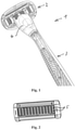
- Figure 1 shows a razor 1 including a razor head 2, a handle 3 and an adapter 4 for connecting the razor head 2 to the handle 3 according to one embodiment of the present disclosure.
- the razor head 2, the adapter 4 and the handle 3 are separate parts, wherein the razor head 2 can be connected to the adapter 4 on one side, and wherein the handle 3 can be connected to the adapter 4 on another opposite side.
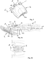
- FIG. 2 shows a front view of a razor head according to one embodiment of the present disclosure.
- the razor head housing may comprise one or more housing parts, in particular a front housing part and a rear housing part, wherein blades 5 (in the shown embodiment five razor blades) are contained within the housing.
- FIG. 3 shows an adapter 4 according to one embodiment of the present disclosure.
- the adapter 4 is designed to be connected to the razor head 2 and is designed to be connected to a handle 3.
- the razor head can be rotated with respect to the adapter around a (virtual) razor head axis 6 which is defined by the connection elements of the adapter and the razor head which will be explained below in more detail.
- a razor head biasing member 7 is arranged within the adapter, wherein a pusher element 8 of the biasing member 7 protrudes out of the adapter to engage a surface of the razor head. With that, the manufacturing and mounting procedure is facilitated.
- Figure 4a shows a cross-section through a razor head 2, an adapter 4 and part of a handle 3 according to one embodiment of the present disclosure.
- the razor head biasing member 7 preferably comprises a compression spring element 9 and a pusher element 8 for pushing the razor head 2 into a rest position.
- the rest position of the razor head 2 can be defined as being a maximum rotational position of the razor head with respect to the adapter 4.
- the pusher element 8 engages a surface or a portion of the razor head 2, when the razor head 2 is mounted on the adapter 4.
- the razor head 2 can be rotatable around the razor head axis 6 which is perpendicular or substantially perpendicular to the centroidal axis 10 of the handle 3 extending along the handle by at least up to 20 degrees, when the handle is held stationary, in particular from 0 degrees up to 40 degrees (wherein 0 degrees corresponds to the rest position of the razor head, and 40 degrees corresponds to the fully pivoted position of the razor head).
- the compression spring 9 of the razor head biasing member is compressed when the razor head 2 is rotated away from the rest position (in Figure 2 in clockwise direction), in particular when a user moves the razor head along a curved surface of the skin.
- the adapter 4 extends from a handle end 4a to a head end 4b, wherein the adapter 4 comprises an opening 11 extending from the head end 4b to an internal portion of the adapter, and wherein the razor head biasing member 7 is mounted within that opening 11 of the adapter 4.
- the main components of the razor head biasing member, in particular the spring element 7 remains in a clean state during use and is less affected from shaving foam which might negatively influence the functioning of the spring element.
- the opening 11 of the adapter preferably has one or more protrusions 14 on the side of the adapter which is designed to be connected to the razor head 2, wherein the pusher element 8 has one or more stop elements 15 for engaging the one or more protrusions 14 so that the pusher element cannot extend beyond a maximum extension out of the adapter.
- This feature also facilitates the mounting of the razor head biasing member within the adapter.
- the protrusions 14 of the adapter and the stop elements 15 may - in addition or alternatively - be arranged on two lateral sides within opening 11.
- the adapter may have surfaces 15' at one end of the opening 11 which is tilted with respect to the axis of the opening in order to facilitate mounting of the pusher element into the opening.
- one tilted surface 15' is provided for each stop element 15 so that their engagement pushed the corresponding protrusion 14 slightly outwardly when the pusher element is inserted into the opening 11.
- the adapter may also comprise at least one aperture 12 which extends from the handle end 4a to an internal portion of the adapter 4.
- the aperture 12 of the adapter preferably has at least one protrusion 13 for engaging the handle.
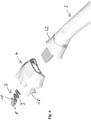
- Figure 5 shows an explosion view of a razor head 2, a razor head biasing member 7, an adapter 4 and a handle 3 in demounted state for a better understanding of the present disclosure.
- Figure 6 shows an explosion view of a razor head biasing member, an adapter and a handle in demounted state according to another embodiment of the present disclosure.
- the pusher element 8 and the compression spring 9 are made of a single piece, in particular by injection moulding using a plastic material. This facilitates the manufacturing of the razor head biasing member 7, because it can be mounted within the adapter as a single piece.
- the compression spring 9 preferably has an undulating shape comprising several connected U-shaped structures, wherein the undulating shape preferably extends within one plane.
- the adapter 4 may have two internal planar surfaces neighboring the one or more U-shaped structures on both sides in order to provide a guide structure within the adapter 4 for a controlled compression of the compression spring.
- the razor head biasing member 7 may have, in an unmounted and unbiased situation, a length in the range of 10 mm to 20 mm, a width in the range of 2 mm to 12 mm, and a height in the range of 0.8 mm to 3 mm.
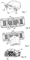
- the adapter 4 comprises one or more elements 17 having the shape of an arc.
- the head end 4b of the adapter 4 preferably comprises a pair of arms 16, each arm having an element 17 having the shape of an arc.
- the razor head housing or a part of the razor head housing may also have one or more first elements 18 having the shape of an arc which are designed to engage the one or more arc elements 17 of the adapter.
- the one or more first arc elements 18 of the razor head may have one or more convex surfaces for engaging and/or mating one or more concave surfaces of the one or more arc elements 17 of the adapter.
- the arc elements 17, 18 of the adapter and of the housing cooperate with each other to provide a well-defined rotation of the razor head relative to the adapter around virtual axis 6 (see Fig. 3 ), which also ensures a better functionality of the razor head biasing member.
- the razor head housing or a part of the razor head housing may also have one or more second elements 19 having the shape of an arc which are designed to engage the one or more arc elements 17 of the adapter.
- the one or more second arc elements 19 of the razor head may have one or more convex surfaces for engaging and/or mating one or more concave surfaces of the one or more arc elements 17 of the adapter (see Figure 9 ). With that, it is possible that the one or more arc elements 17 of the adapter are held between the one or more first arc elements 18 of the razor head and the one or more second arc elements 19 of the razor head.
- the one or more concave surfaces of the one or more adapter arc elements 17 and the one or more convex surfaces of the one or more first arc elements 18 of the razor head may correspond to partial surfaces of a cylindrical tube having a first radius of curvature.
- the one or more concave surfaces of the one or more adapter arc elements 17 and the one or more convex surfaces of the one or more second arc elements 19 of the razor head may correspond to partial surfaces of a cylindrical tube having a second radius of curvature, wherein the first radius of curvature is smaller than the second radius of curvature.
- the first radius of curvature is within range of 2 to 8 mm, preferably 3 to 5 mm
- the second radius of curvature is within a range of 5 to 10 mm, preferably 4 to 8 mm.
- the one or more arc elements 17 of the adapter may have one or more protrusions 20 for engaging one or more stop elements 21 of the razor housing.
- the one or more arc elements 17 of the adapter may have one or more protrusions 20 on their concave surfaces for engaging one or more stop elements 21 which are arranged neighboring to or integrally formed at the one or more second arc elements 19 of the razor head.
- the one or more protrusions 20 of the one or more arc elements of the adapter preferably engage the one or more stop elements 21 of the razor housing when the razor head is in the rest position.
- the razor head 2 may be connected to a handle 3 through the adapter 4.
- the handle may comprise a tongue or an extension 22 which is suitable to be received within the aperture 12 of the adapter, wherein the tongue or extension 22 of the handle is adapted to be slidingly received within the aperture of the adapter.
- the handle and the adapter may be designed to be connected by means of a snap-fit connection (see protrusion 13 in Fig. 4 ).
- a rear view of the adapter 4 showing the aperture 12 can be seen in Figure 10 .
- the handle 3 may comprise a ring element 23 which can be actuated or rotated at least partially around the axis of the handle for releasing the connection between the handle 3 and the adapter 4.
- the ring element 23 may be biased in a rest position for keeping the adapter in a locked state with respect to the handle.
- the adapter 4 may comprise one or more protrusions 13 on the side of the handle, wherein the one or more protrusions 13 are preferably arranged within a recessed portion of the adapter.
- the ring element may comprise one or more engagement elements for engaging the one or more protrusions of the adapter to keep the adapter in a locked state with respect to the handle.
- the one or more engagement elements may be disengaged from the one or more protrusions of the adapter by actuating or rotating the ring element.
Landscapes
- Life Sciences & Earth Sciences (AREA)
- Forests & Forestry (AREA)
- Engineering & Computer Science (AREA)
- Mechanical Engineering (AREA)
- Dry Shavers And Clippers (AREA)
- Cleaning And Drying Hair (AREA)
Abstract
Description
- The present disclosure relates to the field of razors, in particular to razors for wet shaving.
- Razors for wet shaving having a handle, a razor head and an adapter for connecting the razor head to the handle are known in the art, for example from
EP 2 879 845 B1 - The object of the present disclosure is to provide razor head and an adapter ensuring a safe connection between the razor head and a handle, wherein the manufacturing and mounting is facilitated. It is another object of the present invention to achieve improved pivoting properties of the razor head relative to the handle.
- The present disclosure relates to a razor head and an adapter as defined in
claim 1. The dependent claims depict advantageous embodiments of the present disclosure. - The adapter is designed to be connected to the razor head and is designed to be connected to a handle, wherein the razor head can be rotated with respect to the adapter around a razor head axis. According to the present disclosure, a razor head biasing member is at least partially arranged within the adapter. With that, the manufacturing and mounting procedure is facilitated.
- The razor head biasing member preferably comprises a compression spring element and a pusher element for pushing the razor head into a rest position. The compression spring is fully contained within the adapter, whereas the pusher element is only partially contained within the adapter. The rest position of the razor head can be defined as being a maximum rotational position of the razor head with respect to the adapter. The portion of the pusher element which protrudes from the adapter engages a portion of the razor head, when the razor head is mounted on the adapter. The razor head may be rotatable around the razor head axis which is perpendicular or substantially perpendicular to the centroidal axis of the handle extending along the handle by at least up to 20 degrees, when the handle is held stationary, in particular from 0 degrees up to 40 degrees (wherein 0 degrees corresponds to the rest position of the razor head, and 40 degrees corresponds to the fully pivoted position of the razor head). The compression spring of the razor head biasing member may be compressed when the razor head is rotated away from the rest position, in particular when a user moves the razor head along a curved surface of the skin.
- The adapter is preferably adapted to extend from a handle end to a head end, wherein the adapter comprises an opening extending from the head end to an internal portion of the adapter, and wherein the razor head biasing member is mounted within that opening of the adapter. This facilitates the mounting of the razor head biasing member to the adapter. In addition, the main components of the razor head biasing member, in particular the spring element, remains in a clean state during use and is less affected from shaving foam which might negatively influence the functioning of the spring element.
- The adapter may also comprise at least one aperture which extends from the handle end to an internal portion of the adapter. The aperture of the adapter preferably has one or more protrusions on the side of the adapter which is designed to be connected to the razor head, wherein the pusher element has one or more stop elements for engaging the one or more protrusions so that the pusher element cannot extend beyond a maximum extension out of the adapter. This feature also facilitates the mounting of the razor head biasing member within the adapter.
- According to another aspect of the present disclosure, the pusher element and the compression spring are made of a single piece, in particular by injection moulding. This facilitates the manufacturing of the razor head biasing member, because it can be mounted within the adapter as a single piece. The compression spring preferably has an undulating shape comprising one or more U-shaped structures, wherein the undulating shape preferably extends within one plane. The adapter may have two planar surfaces neighboring the one or more U-shaped structures on both sides in order to provide a guide structure within the adapter for a controlled compression of the compression spring.
- The razor head biasing member may have, in an unmounted and unbiased situation, a length in the range of 10 mm to 20 mm, a width in the range of 2 mm to 12 mm, and a height in the range of 0.8 mm to 3 mm.
- The razor head comprises a housing which is designed to be connected to the adapter. It should be understood that the razor head housing may comprise one or more housing parts, in particular a front housing part and a rear housing part, wherein at least one razor blade (in particular three, four or five razor blades) is contained within the housing.
- According to another aspect of the present disclosure, the adapter comprises one or more elements having the shape of an arc. The head end of the adapter preferably comprises a pair of arms, each arm having an element having the shape of an arc. The razor head housing or a part of the razor head housing may also have one or more first elements having the shape of an arc which are designed to engage the one or more arc elements of the adapter. In particular, the one or more first arc elements of the razor head may have one or more convex surfaces for engaging and/or mating one or more concave surfaces of the one or more arc elements of the adapter. The arc elements of the adapter and of the housing cooperate with each other to provide a well-defined rotation of the razor head relative to the adapter, which also ensures a better functionality of the razor head biasing member.
- The razor head housing or a part of the razor head housing may also have one or more second elements having the shape of an arc which are designed to engage the one or more arc elements of the adapter. The one or more second arc elements of the razor head may have one or more concave surfaces for engaging and/or mating one or more convex surfaces of the one or more arc elements of the adapter. With that, it is possible that the one or more arc elements of the adapter are held between the one or more first arc elements of the razor head and the one or more second arc elements of the razor head.
- The one or more concave surfaces of the one or more adapter arc elements and the one or more convex surfaces of the one or more first arc elements of the razor head may correspond to partial surfaces of a cylindrical tube having a first radius of curvature. And the one or more convex surfaces of the one or more adapter arc elements and the one or more concave surfaces of the one or more second arc elements of the razor head may correspond to partial surfaces of a cylindrical tube having a second radius of curvature, wherein the first radius of curvature is smaller than the second radius of curvature. In particular, the first radius of curvature is within range of 2 to 8 mm, preferably 4 to 6 mm, and wherein the second radius of curvature is within a range of 5 to 10 mm, preferably 6.5 to 8 mm.
- In addition, the one or more arc elements of the adapter may have one or more protrusions for engaging one or more stop elements of the razor housing. And the one or more arc elements of the adapter may have one or more protrusions on their concave surfaces for engaging one or more stop elements which are arranged neighboring to or integrally formed at the one or more second arc elements of the razor head. The one or more protrusions of the one or more arc elements of the adapter preferably engage the one or more stop elements of the razor housing when the razor head is in the rest position.
- According to the present disclosure, the razor head may be connected to a handle over the adapter. The handle may comprise a tongue or an extension which is suitable to be received within the adapter, wherein the tongue or extension of the handle is adapted to be slidingly received within the aperture of the adapter. In addition, the handle and the adapter may be designed to be connected by means of a snap-fit connection.
- The handle may comprise a ring element which can be actuated or rotated at least partially around the axis of the handle for releasing the connection between the handle and the adapter. The ring element may be biased in a rest position for keeping the adapter in a locked state with respect to the handle.
- The adapter may comprise one or more protrusions on the side of the handle, wherein the one or more protrusions are preferably arranged within a recessed portion of the adapter. The ring element may comprise one or more engagement elements for engaging the one or more protrusions of the adapter to keep the adapter in a locked state with respect to the handle. The one or more engagement elements may be disengaged from the one or more protrusions of the adapter by actuating or rotating the ring element.
- Additional details and features of the disclosure are described with reference to the following figures in which
- Figure 1
- shows a razor including a razor head, a handle and an adapter for connecting the razor head to the handle according to one embodiment of the present disclosure;
- Figure 2
- shows a front view of a razor head according to one embodiment of the present disclosure;
- Figure 3
- shows an adapter according to one embodiment of the present disclosure;
- Figure 4a
- shows a cross-section through a razor head, an adapter and part of a handle according to one embodiment of the present disclosure;
- Figure 4b
- shows a cross-section through an adapter according to one embodiment of the present disclosure;
- Figure 5
- shows an explosion view of a razor head, a razor head biasing member, an adapter and a handle in demounted state according to one embodiment of the present disclosure;
- Figure 6
- shows an explosion view of a razor head biasing member, an adapter and a handle in demounted state according to another embodiment of the present disclosure;
- Figure 7
- shows an adapter according to an embodiment of the present disclosure;
- Figure 8
- shows a rear view of a razor head according to an embodiment of the present disclosure;
- Figure 9
- shows a razor had connected to an adapter according to an embodiment of the present disclosure; and
- Figure 10
- shows a rear view of an adapter according to an embodiment of the present disclosure.
- Embodiments of the writing instrument according to the disclosure will be described with reference to the figures as follows.
-
Figure 1 shows arazor 1 including arazor head 2, ahandle 3 and anadapter 4 for connecting therazor head 2 to thehandle 3 according to one embodiment of the present disclosure. As can be seen inFigure 5 , therazor head 2, theadapter 4 and thehandle 3 are separate parts, wherein therazor head 2 can be connected to theadapter 4 on one side, and wherein thehandle 3 can be connected to theadapter 4 on another opposite side. -
Figure 2 shows a front view of a razor head according to one embodiment of the present disclosure. The razor head housing may comprise one or more housing parts, in particular a front housing part and a rear housing part, wherein blades 5 (in the shown embodiment five razor blades) are contained within the housing. -
Figure 3 shows anadapter 4 according to one embodiment of the present disclosure. As mentioned, theadapter 4 is designed to be connected to therazor head 2 and is designed to be connected to ahandle 3. The razor head can be rotated with respect to the adapter around a (virtual) razor head axis 6 which is defined by the connection elements of the adapter and the razor head which will be explained below in more detail. According to the present disclosure, a razorhead biasing member 7 is arranged within the adapter, wherein apusher element 8 of the biasingmember 7 protrudes out of the adapter to engage a surface of the razor head. With that, the manufacturing and mounting procedure is facilitated. -
Figure 4a shows a cross-section through arazor head 2, anadapter 4 and part of ahandle 3 according to one embodiment of the present disclosure. The razorhead biasing member 7 preferably comprises acompression spring element 9 and apusher element 8 for pushing therazor head 2 into a rest position. The rest position of therazor head 2 can be defined as being a maximum rotational position of the razor head with respect to theadapter 4. Thepusher element 8 engages a surface or a portion of therazor head 2, when therazor head 2 is mounted on theadapter 4. Therazor head 2 can be rotatable around the razor head axis 6 which is perpendicular or substantially perpendicular to thecentroidal axis 10 of thehandle 3 extending along the handle by at least up to 20 degrees, when the handle is held stationary, in particular from 0 degrees up to 40 degrees (wherein 0 degrees corresponds to the rest position of the razor head, and 40 degrees corresponds to the fully pivoted position of the razor head). Thecompression spring 9 of the razor head biasing member is compressed when therazor head 2 is rotated away from the rest position (inFigure 2 in clockwise direction), in particular when a user moves the razor head along a curved surface of the skin. - The
adapter 4 extends from a handle end 4a to a head end 4b, wherein theadapter 4 comprises anopening 11 extending from the head end 4b to an internal portion of the adapter, and wherein the razorhead biasing member 7 is mounted within thatopening 11 of theadapter 4. This facilitates the mounting of the razorhead biasing member 4 to or within theadapter 4. In addition, the main components of the razor head biasing member, in particular thespring element 7, remains in a clean state during use and is less affected from shaving foam which might negatively influence the functioning of the spring element. - The
opening 11 of the adapter preferably has one ormore protrusions 14 on the side of the adapter which is designed to be connected to therazor head 2, wherein thepusher element 8 has one ormore stop elements 15 for engaging the one ormore protrusions 14 so that the pusher element cannot extend beyond a maximum extension out of the adapter. This feature also facilitates the mounting of the razor head biasing member within the adapter. As shown inFigure 4b , theprotrusions 14 of the adapter and thestop elements 15 may - in addition or alternatively - be arranged on two lateral sides withinopening 11. The adapter may have surfaces 15' at one end of theopening 11 which is tilted with respect to the axis of the opening in order to facilitate mounting of the pusher element into the opening. Preferably, one tilted surface 15' is provided for eachstop element 15 so that their engagement pushed the correspondingprotrusion 14 slightly outwardly when the pusher element is inserted into theopening 11. - The adapter may also comprise at least one
aperture 12 which extends from the handle end 4a to an internal portion of theadapter 4. Theaperture 12 of the adapter preferably has at least one protrusion 13 for engaging the handle. -
Figure 5 shows an explosion view of arazor head 2, a razorhead biasing member 7, anadapter 4 and ahandle 3 in demounted state for a better understanding of the present disclosure. -
Figure 6 shows an explosion view of a razor head biasing member, an adapter and a handle in demounted state according to another embodiment of the present disclosure. In this embodiment, thepusher element 8 and thecompression spring 9 are made of a single piece, in particular by injection moulding using a plastic material. This facilitates the manufacturing of the razorhead biasing member 7, because it can be mounted within the adapter as a single piece. As shown, thecompression spring 9 preferably has an undulating shape comprising several connected U-shaped structures, wherein the undulating shape preferably extends within one plane. Theadapter 4 may have two internal planar surfaces neighboring the one or more U-shaped structures on both sides in order to provide a guide structure within theadapter 4 for a controlled compression of the compression spring. - The razor
head biasing member 7 may have, in an unmounted and unbiased situation, a length in the range of 10 mm to 20 mm, a width in the range of 2 mm to 12 mm, and a height in the range of 0.8 mm to 3 mm. - According to another aspect of the present disclosure as shown in
Figure 7 , theadapter 4 comprises one ormore elements 17 having the shape of an arc. The head end 4b of theadapter 4 preferably comprises a pair ofarms 16, each arm having anelement 17 having the shape of an arc. The razor head housing or a part of the razor head housing may also have one or morefirst elements 18 having the shape of an arc which are designed to engage the one ormore arc elements 17 of the adapter. In particular, the one or morefirst arc elements 18 of the razor head may have one or more convex surfaces for engaging and/or mating one or more concave surfaces of the one ormore arc elements 17 of the adapter. Thearc elements Fig. 3 ), which also ensures a better functionality of the razor head biasing member. - As shown in
Figure 8 , the razor head housing or a part of the razor head housing may also have one or moresecond elements 19 having the shape of an arc which are designed to engage the one ormore arc elements 17 of the adapter. The one or moresecond arc elements 19 of the razor head may have one or more convex surfaces for engaging and/or mating one or more concave surfaces of the one ormore arc elements 17 of the adapter (seeFigure 9 ). With that, it is possible that the one ormore arc elements 17 of the adapter are held between the one or morefirst arc elements 18 of the razor head and the one or moresecond arc elements 19 of the razor head. - The one or more concave surfaces of the one or more
adapter arc elements 17 and the one or more convex surfaces of the one or morefirst arc elements 18 of the razor head may correspond to partial surfaces of a cylindrical tube having a first radius of curvature. And the one or more concave surfaces of the one or moreadapter arc elements 17 and the one or more convex surfaces of the one or moresecond arc elements 19 of the razor head may correspond to partial surfaces of a cylindrical tube having a second radius of curvature, wherein the first radius of curvature is smaller than the second radius of curvature. In particular, the first radius of curvature is within range of 2 to 8 mm, preferably 3 to 5 mm, and wherein the second radius of curvature is within a range of 5 to 10 mm, preferably 4 to 8 mm. - In addition, the one or
more arc elements 17 of the adapter may have one ormore protrusions 20 for engaging one or more stop elements 21 of the razor housing. In particular, the one ormore arc elements 17 of the adapter may have one ormore protrusions 20 on their concave surfaces for engaging one or more stop elements 21 which are arranged neighboring to or integrally formed at the one or moresecond arc elements 19 of the razor head. The one ormore protrusions 20 of the one or more arc elements of the adapter preferably engage the one or more stop elements 21 of the razor housing when the razor head is in the rest position. - According to the present disclosure, the
razor head 2 may be connected to ahandle 3 through theadapter 4. The handle may comprise a tongue or anextension 22 which is suitable to be received within theaperture 12 of the adapter, wherein the tongue orextension 22 of the handle is adapted to be slidingly received within the aperture of the adapter. In addition, the handle and the adapter may be designed to be connected by means of a snap-fit connection (see protrusion 13 inFig. 4 ). A rear view of theadapter 4 showing theaperture 12 can be seen inFigure 10 . - The
handle 3 may comprise aring element 23 which can be actuated or rotated at least partially around the axis of the handle for releasing the connection between thehandle 3 and theadapter 4. Thering element 23 may be biased in a rest position for keeping the adapter in a locked state with respect to the handle. - As already mentioned, the
adapter 4 may comprise one or more protrusions 13 on the side of the handle, wherein the one or more protrusions 13 are preferably arranged within a recessed portion of the adapter. The ring element may comprise one or more engagement elements for engaging the one or more protrusions of the adapter to keep the adapter in a locked state with respect to the handle. The one or more engagement elements may be disengaged from the one or more protrusions of the adapter by actuating or rotating the ring element. - Although the present disclosure has been described above and is defined in the attached embodiments, it should be understood that the disclosure may alternatively be defined in accordance with the following embodiments:
- 1. A razor head (2) and an adapter (4), wherein the adapter (4) is designed to be connected to the razor head (2) and is designed to be connected to a handle (3), wherein the razor head (2) can be rotated with respect to the adapter (4), characterized by a razor head biasing member (7) which is at least partially arranged within the adapter (4).
- 2. The razor head and adapter of
embodiment 1, wherein the razor head biasing member (7) comprises a compression spring element (9) and a pusher element (8) for pushing the razor head into a rest position, wherein the compression spring (8) is fully contained within the adapter, and wherein the pusher element (9) is only partially contained within the adapter. - 3. The razor head and adapter of
embodiment - 4. The razor head and adapter of one of the preceding embodiments, wherein the razor head (2) is rotatable around a razor head axis (6) which is substantially perpendicular to the centroidal axis (10) of the handle extending along the handle by at least up to 20 degrees, when the handle is held stationary, in particular from 0 degrees up to 40 degrees.
- 5. The razor head and adapter of one of the preceding embodiments, wherein the compression spring (9) of the razor head biasing member (7) is compressed when the razor head (2) is rotated away from the rest position.
- 6. The razor head and adapter of one of the preceding embodiments, wherein the adapter (4) is adapted to extend from a handle end (4a) to a head end (4b), the adapter comprising an opening (11) extending from the head end (4b) to an internal portion of the adapter, wherein the razor head biasing member (7) is mounted within that opening (11) of the adapter.
- 7. The razor head and adapter of one of the preceding embodiments, wherein the adapter comprises an aperture (12) which extends from the handle end (4a) to an internal portion of the adapter.
- 8. The razor head and adapter of one of the preceding embodiments, wherein the pusher element (8) engages the razor head (2), when the razor head is mounted on the adapter.
- 9. The razor head and adapter of one of the preceding embodiments, wherein the opening (11) of the adapter has one or more protrusions (14) on the side of the adapter which is designed to be connected to the razor head, and wherein the pusher element (8) has one or more stop elements (15) for engaging the one or more protrusions (14) so that the pusher element (8) cannot extend beyond a maximum extension out of the adapter (4).
- 10. The razor head and adapter of one of the preceding embodiments, wherein the pusher element (8) and the compression spring (9) are made of a single piece, in particular by injection moulding.
- 11. The razor head and adapter of one of the preceding embodiments, wherein the compression spring (9) has an undulating shape comprising one or more U-shaped structures, wherein the undulating shape preferably extends within one plane.
- 12. The razor head and adapter of one of the preceding embodiments, wherein the razor head biasing member (7) has, in an unmounted and unbiased situation, a length in the range of 10 mm to 20 mm, a width in the range of 2 mm to 12 mm, and a height in the range of 0.8 mm to 3 mm.
- 13. The razor head and adapter of one of the preceding embodiments, wherein the adapter comprises one or more elements (17) having the shape of an arc.
- 14. The razor head and adapter of one of the preceding embodiments, wherein a head end (4b) of the adapter comprises a pair of arms (16), each arm having an element (17) having the shape of an arc.
- 15. The razor head and adapter of one of the preceding embodiments, wherein the razor head (2) comprises a housing which is designed to be connected to the adapter.
- 16. The razor head and adapter of one of the preceding embodiments, wherein the razor head housing comprises one or more housing parts.
- 17. The razor head and adapter of one of the preceding embodiments, wherein the razor head housing or a part of the razor head housing has one or more first elements (18) having the shape of an arc which are designed to engage the one or more arc elements (17) of the adapter.
- 18. The razor head and adapter of one of the preceding embodiments, wherein the one or more first arc elements (18) of the razor head have one or more convex surfaces for engaging and/or mating one or more concave surfaces of the one or more arc elements (17) of the adapter.
- 19. The razor head and adapter of one of the preceding embodiments, wherein the razor head housing or a part of the razor head housing has one or more second elements (19) having the shape of an arc which are designed to engage the one or more arc elements (17) of the adapter.
- 20. The razor head and adapter of one of the preceding embodiments, wherein the one or more second arc elements (19) of the razor head have one or more convex surfaces for engaging and/or mating one or more concave surfaces of the one or more arc elements (17) of the adapter.
- 21. The razor head and adapter of one of the preceding embodiments, wherein the one or more arc elements (17) of the adapter are held between the one or more first arc elements (18) of the razor head and the one or more second arc elements (19) of the razor head.
- 22. The razor head and adapter of one of the preceding embodiments, wherein the one or more concave surfaces of the one or more adapter arc elements (17) and the one or more convex surfaces of the one or more first arc elements (18) of the razor head correspond to partial surfaces of a cylindrical tube having a first radius of curvature.
- 23. The razor head and adapter of one of the preceding embodiments, wherein the one or more convex surfaces of the one or more adapter arc elements (17) and the one or more concave surfaces of the one or more second arc elements (18) of the razor head correspond to partial surfaces of a cylindrical tube having a second radius of curvature.
- 24. The razor head and adapter of one of the preceding embodiments, wherein the first radius of curvature is smaller than the second radius of curvature.
- 25. The razor head and adapter of one of the preceding embodiments, wherein the first radius of curvature is within range of 2 to 8 mm, preferably 3 to 5 mm, and wherein the second radius of curvature is within a range of 5 to 10 mm, preferably 4 to 8 mm.
- 26. The razor head and adapter of one of the preceding embodiments, wherein the one or more arc elements (17) of the adapter have one or more protrusions (20) for engaging one or more stop elements (21) of the razor housing.
- 27. The razor head and adapter of one of the preceding embodiments, wherein the one or more arc elements (17) of the adapter have one or more protrusions (20) on their concave surfaces for engaging one or more stop elements (21) which are arranged neighboring to or integrally formed at the one or more second arc elements (19) of the razor head.
- 28. The razor head and adapter of one of the preceding embodiments, wherein the one or more protrusions (20) of the one or more arc elements (17) of the adapter engage the one or more stop elements (21) of the razor housing when the razor head is in the rest position.
- 29. The razor head and adapter of one of the preceding embodiments, wherein the razor head comprises one or more razor blades (5), in particular three, four or five razor blades.
- 30. A razor (1) comprising the razor head (2) and the adapter (4) according to one of the preceding embodiments, further comprising a handle (3) which is designed to be connected to the adapter.
- 31. The razor according to embodiment 30, wherein the handle comprises a tongue or an extension (22) which is suitable to be received within the adapter (4).
- 32. The razor according to embodiment 31, wherein the tongue or extension (22) of the handle is adapted to be slidingly received within the aperture (12) of the adapter.
- 33. The razor according to one of embodiments 30 to 32, wherein the handle and the adapter are designed to be connected by means of a snap-fit connection.
- 34. The razor according to one of embodiments 30 to 33, wherein the handle comprises a ring element (23) which can be actuated or rotated at least partially around the axis of the handle for releasing the connection between the handle and the adapter.
- 35. The razor according to embodiment 34, wherein the ring element (23) is biased in a rest position for keeping the adapter in a locked state with respect to the handle.
- 36. The razor according to one of embodiments 30 to 35, wherein the adapter comprises one or more protrusions (13) on the side of the handle, wherein the one or more protrusions (13) are preferably arranged within a recessed portion of the adapter.
- 37. The razor according to one of embodiments 34 to 36, wherein the ring element (23) comprises one or more engagement elements for engaging the one or more protrusions (13) of the adapter to keep the adapter in a locked state with respect to the handle.
- 38. The razor according to one of embodiments 34 to 37, wherein the one or more engagement elements can be disengaged from the one or more protrusions of the adapter by rotating the ring element (23).
- 39. The razor according to one of embodiments 30 to 38, wherein the adapter is fixedly or removably attached to the handle.
Claims (15)
- A razor head (2) and an adapter (4), wherein the adapter (4) is designed to be connected to the razor head (2) and is designed to be connected to a handle (3), wherein the razor head (2) can be rotated with respect to the adapter (4), characterized by a razor head biasing member (7) which is at least partially arranged within the adapter (4).
- The razor head and adapter of claim 1, wherein the razor head biasing member (7) comprises a compression spring element (9) and a pusher element (8) for pushing the razor head into a rest position, wherein the compression spring (8) is fully contained within the adapter, and wherein the pusher element (9) is only partially contained within the adapter.
- The razor head and adapter of claim 1 or 2, wherein the adapter (4) is adapted to extend from a handle end (4a) to a head end (4b), the adapter comprising an opening (11) extending from the head end (4b) to an internal portion of the adapter, wherein the razor head biasing member (7) is mounted within that opening (11) of the adapter.
- The razor head and adapter of one of the preceding claims, wherein the adapter comprises an aperture (12) which extends from the handle end (4a) to an internal portion of the adapter.
- The razor head and adapter of one of the preceding claims, wherein the opening (11) of the adapter has one or more protrusions (14) on the side of the adapter which is designed to be connected to the razor head, and wherein the pusher element (8) has one or more stop elements (15) for engaging the one or more protrusions (14) so that the pusher element (8) cannot extend beyond a maximum extension out of the adapter (4).
- The razor head and adapter of one of the preceding claims, wherein the pusher element (8) and the compression spring (9) are made of a single piece.
- The razor head and adapter of one of the preceding claims, wherein the compression spring (9) has an undulating shape comprising one or more U-shaped structures, wherein the undulating shape preferably extends within one plane.
- The razor head and adapter of one of the preceding claims, wherein the adapter comprises one or more elements (17) having the shape of an arc.
- The razor head and adapter of one of the preceding claims, wherein the razor head housing or a part of the razor head housing has one or more first elements (18) having the shape of an arc which are designed to engage the one or more arc elements (17) of the adapter.
- The razor head and adapter of one of the preceding claims, wherein the razor head housing or a part of the razor head housing has one or more second elements (19) having the shape of an arc which are designed to engage the one or more arc elements (17) of the adapter.
- The razor head and adapter of one of the preceding claims, wherein the one or more arc elements (17) of the adapter have one or more protrusions (20) for engaging one or more stop elements (21) of the razor housing.
- The razor head and adapter of one of the preceding claims, wherein the one or more arc elements (17) of the adapter have one or more protrusions (20) on their concave surfaces for engaging one or more stop elements (21) which are arranged neighboring to or integrally formed at the one or more second arc elements (19) of the razor head.
- The razor head and adapter of one of the preceding claims, wherein the one or more protrusions (20) of the one or more arc elements (17) of the adapter engage the one or more stop elements (21) of the razor housing when the razor head is in the rest position.
- A razor (1) comprising the razor head (2) and the adapter (4) according to one of the preceding claims, further comprising a handle (3) which is designed to be connected to the adapter.
- The razor according to claim 14, wherein the handle comprises a ring element (23) which can be actuated or rotated at least partially around the axis of the handle for releasing the connection between the handle and the adapter.
Priority Applications (7)
| Application Number | Priority Date | Filing Date | Title |
|---|---|---|---|
| PL20187986.3T PL3944935T3 (en) | 2020-07-27 | 2020-07-27 | Adapter for a razor system |
| EP20187986.3A EP3944935B1 (en) | 2020-07-27 | 2020-07-27 | Adapter for a razor system |
| ES20187986T ES2962917T3 (en) | 2020-07-27 | 2020-07-27 | Adapter for a razor system |
| PCT/EP2021/069566 WO2022023036A1 (en) | 2020-07-27 | 2021-07-14 | Adapter for a razor system |
| CN202180045511.3A CN115734853B (en) | 2020-07-27 | 2021-07-14 | Adapter for shaver systems |
| BR112022027074A BR112022027074A2 (en) | 2020-07-27 | 2021-07-14 | ADAPTER FOR A SHAVING APPLIANCE SYSTEM |
| US18/006,399 US20230294316A1 (en) | 2020-07-27 | 2021-07-14 | Adapter for razor system |
Applications Claiming Priority (1)
| Application Number | Priority Date | Filing Date | Title |
|---|---|---|---|
| EP20187986.3A EP3944935B1 (en) | 2020-07-27 | 2020-07-27 | Adapter for a razor system |
Publications (3)
| Publication Number | Publication Date |
|---|---|
| EP3944935A1 true EP3944935A1 (en) | 2022-02-02 |
| EP3944935C0 EP3944935C0 (en) | 2023-10-25 |
| EP3944935B1 EP3944935B1 (en) | 2023-10-25 |
Family
ID=71833272
Family Applications (1)
| Application Number | Title | Priority Date | Filing Date |
|---|---|---|---|
| EP20187986.3A Active EP3944935B1 (en) | 2020-07-27 | 2020-07-27 | Adapter for a razor system |
Country Status (7)
| Country | Link |
|---|---|
| US (1) | US20230294316A1 (en) |
| EP (1) | EP3944935B1 (en) |
| CN (1) | CN115734853B (en) |
| BR (1) | BR112022027074A2 (en) |
| ES (1) | ES2962917T3 (en) |
| PL (1) | PL3944935T3 (en) |
| WO (1) | WO2022023036A1 (en) |
Cited By (4)
| Publication number | Priority date | Publication date | Assignee | Title |
|---|---|---|---|---|
| US20210031391A1 (en) * | 2019-07-31 | 2021-02-04 | Bic Violex S.A. | Mechanical assembly of a skin care device, skin care device and process for manufacturing thereof |
| EP4494823A1 (en) * | 2023-07-18 | 2025-01-22 | BIC Violex Single Member S.A. | Razor interconnecting mechanism |
| USD1092854S1 (en) * | 2023-04-07 | 2025-09-09 | Dorco Co., Ltd. | Razor handle |
| USD1092856S1 (en) * | 2023-05-18 | 2025-09-09 | Dorco Co., Ltd. | Razor handle |
Families Citing this family (1)
| Publication number | Priority date | Publication date | Assignee | Title |
|---|---|---|---|---|
| DE102021126490B3 (en) * | 2021-10-13 | 2022-12-29 | Feintechnik Gmbh Eisfeld | Handle with an ejector for a wet razor |
Citations (5)
| Publication number | Priority date | Publication date | Assignee | Title |
|---|---|---|---|---|
| US6421925B1 (en) * | 2000-06-01 | 2002-07-23 | American Society Razor Company | Single piece spring clip for razor |
| US8793880B2 (en) * | 2010-02-16 | 2014-08-05 | The Gillette Company | Shaving razor adapter attaching a shaving razor cartridge to a shaving razor handle |
| US20170087733A1 (en) * | 2015-09-29 | 2017-03-30 | The Gillette Company | Kit Comprising A Razor Cartridge And An Adapter |
| EP2879845B1 (en) | 2012-08-03 | 2018-10-31 | The Gillette Company LLC | Connection between shaving handle and head |
| US20200070375A1 (en) * | 2018-09-05 | 2020-03-05 | The Gillette Company Llc | Razor structure |
Family Cites Families (19)
| Publication number | Priority date | Publication date | Assignee | Title |
|---|---|---|---|---|
| US4413411A (en) * | 1982-02-25 | 1983-11-08 | The Gillette Company | Razor handle |
| GB2116470B (en) * | 1982-03-12 | 1985-09-25 | Gillette Co | Safety razors |
| US4488357A (en) * | 1982-09-17 | 1984-12-18 | The Gillette Company | Safety razor |
| US5016352A (en) * | 1990-03-22 | 1991-05-21 | The Gillette Company | Single button razor |
| US5299354A (en) * | 1990-10-11 | 1994-04-05 | The Gillette Company | Oscillating shaver |
| US5272788A (en) * | 1992-07-23 | 1993-12-28 | Gilstrap Cecil G | Interchangeable tools and handle |
| US5787586A (en) * | 1996-04-10 | 1998-08-04 | The Gillette Company | Shaving system and method |
| US6880253B1 (en) * | 2000-06-23 | 2005-04-19 | Bic Violex S.A. | Razor with a movable shaving head |
| EP1789238B1 (en) * | 2004-09-07 | 2008-03-19 | BIC Violex S.A. | Razor handle and shaver including such a handle |
| US20070050995A1 (en) * | 2005-09-06 | 2007-03-08 | Fred Schnak | Razors |
| EP2387489B1 (en) * | 2009-01-05 | 2014-05-14 | The Gillette Company | Docking mechanism for shaving razors and cartridges |
| MX359010B (en) * | 2012-12-21 | 2018-09-12 | Bic Violex Sa | Shaver with interchangeable cartridge, cartridge and head and handle assembly for such shaver. |
| CN104870149B (en) * | 2012-12-21 | 2017-06-30 | 比克-维尔莱克 | razor |
| DE202013002343U1 (en) * | 2013-03-12 | 2013-04-16 | Silag Handel Ag | Mechanical razor of simplified design |
| US11052558B2 (en) * | 2016-05-31 | 2021-07-06 | The Gillette Company Llc | Adapter for a handle and a cartridge of different razor systems |
| US10137584B2 (en) * | 2016-05-31 | 2018-11-27 | The Gillette Company Llc | Adapter for a handle and a cartridge of different razor systems |
| EP3571025B1 (en) * | 2017-01-17 | 2021-08-11 | BIC-Violex S.A. | A connector adapted for wet shaving cartridges pivotable about two axes |
| EP3398738B1 (en) * | 2017-05-05 | 2020-03-11 | BIC Violex S.A. | Razor handle |
| US11161263B2 (en) * | 2019-08-22 | 2021-11-02 | Harry's, Inc. | Razor cartridge connection and handle |
-
2020
- 2020-07-27 EP EP20187986.3A patent/EP3944935B1/en active Active
- 2020-07-27 PL PL20187986.3T patent/PL3944935T3/en unknown
- 2020-07-27 ES ES20187986T patent/ES2962917T3/en active Active
-
2021
- 2021-07-14 BR BR112022027074A patent/BR112022027074A2/en unknown
- 2021-07-14 CN CN202180045511.3A patent/CN115734853B/en active Active
- 2021-07-14 US US18/006,399 patent/US20230294316A1/en active Pending
- 2021-07-14 WO PCT/EP2021/069566 patent/WO2022023036A1/en not_active Ceased
Patent Citations (5)
| Publication number | Priority date | Publication date | Assignee | Title |
|---|---|---|---|---|
| US6421925B1 (en) * | 2000-06-01 | 2002-07-23 | American Society Razor Company | Single piece spring clip for razor |
| US8793880B2 (en) * | 2010-02-16 | 2014-08-05 | The Gillette Company | Shaving razor adapter attaching a shaving razor cartridge to a shaving razor handle |
| EP2879845B1 (en) | 2012-08-03 | 2018-10-31 | The Gillette Company LLC | Connection between shaving handle and head |
| US20170087733A1 (en) * | 2015-09-29 | 2017-03-30 | The Gillette Company | Kit Comprising A Razor Cartridge And An Adapter |
| US20200070375A1 (en) * | 2018-09-05 | 2020-03-05 | The Gillette Company Llc | Razor structure |
Cited By (5)
| Publication number | Priority date | Publication date | Assignee | Title |
|---|---|---|---|---|
| US20210031391A1 (en) * | 2019-07-31 | 2021-02-04 | Bic Violex S.A. | Mechanical assembly of a skin care device, skin care device and process for manufacturing thereof |
| US11787074B2 (en) * | 2019-07-31 | 2023-10-17 | BIC Violex Single Member S.A. | Mechanical assembly of a skin care device, skin care device and process for manufacturing thereof |
| USD1092854S1 (en) * | 2023-04-07 | 2025-09-09 | Dorco Co., Ltd. | Razor handle |
| USD1092856S1 (en) * | 2023-05-18 | 2025-09-09 | Dorco Co., Ltd. | Razor handle |
| EP4494823A1 (en) * | 2023-07-18 | 2025-01-22 | BIC Violex Single Member S.A. | Razor interconnecting mechanism |
Also Published As
| Publication number | Publication date |
|---|---|
| PL3944935T3 (en) | 2024-02-19 |
| US20230294316A1 (en) | 2023-09-21 |
| BR112022027074A2 (en) | 2023-02-07 |
| CN115734853A (en) | 2023-03-03 |
| EP3944935C0 (en) | 2023-10-25 |
| WO2022023036A1 (en) | 2022-02-03 |
| ES2962917T3 (en) | 2024-03-21 |
| CN115734853B (en) | 2026-04-28 |
| EP3944935B1 (en) | 2023-10-25 |
Similar Documents
| Publication | Publication Date | Title |
|---|---|---|
| EP3944935B1 (en) | Adapter for a razor system | |
| US6442850B1 (en) | Shaving razor using blade cartridge and blade cartridge therefor | |
| AU2007258720B2 (en) | Razor handle | |
| EP2459353B1 (en) | Wet shaver | |
| EP2054199B1 (en) | Shaving blade unit and shaver having such a blade unit | |
| EP1742779B1 (en) | Biasing assembly for a razor and razor using same | |
| CA2461465C (en) | Razor blade system | |
| EP2078593B1 (en) | Razor | |
| US8359751B2 (en) | Shaving blade unit comprising a movable trimming blade protector and shaver having such a blade unit | |
| EP3481606B1 (en) | Shaving component, shaving cartridge, and method of manufacture | |
| EP1641606A1 (en) | Pivotable shaving cartridge and razor including same | |
| CA2557281A1 (en) | Shaving system | |
| JP2002320783A (en) | Shaving razor with rotating blade housing and replaceable blade cartridge therefor | |
| EP3616861B1 (en) | Razor assembly | |
| EP4338903A1 (en) | Razor cartridge and razor assembly | |
| US20230373116A1 (en) | Razor cartridge | |
| CN117320858A (en) | Shaver cartridge and shaver assembly including same |
Legal Events
| Date | Code | Title | Description |
|---|---|---|---|
| PUAI | Public reference made under article 153(3) epc to a published international application that has entered the european phase |
Free format text: ORIGINAL CODE: 0009012 |
|
| STAA | Information on the status of an ep patent application or granted ep patent |
Free format text: STATUS: REQUEST FOR EXAMINATION WAS MADE |
|
| 17P | Request for examination filed |
Effective date: 20200727 |
|
| AK | Designated contracting states |
Kind code of ref document: A1 Designated state(s): AL AT BE BG CH CY CZ DE DK EE ES FI FR GB GR HR HU IE IS IT LI LT LU LV MC MK MT NL NO PL PT RO RS SE SI SK SM TR |
|
| RAP3 | Party data changed (applicant data changed or rights of an application transferred) |
Owner name: BIC VIOLEX SINGLE MEMBER S.A. |
|
| GRAP | Despatch of communication of intention to grant a patent |
Free format text: ORIGINAL CODE: EPIDOSNIGR1 |
|
| STAA | Information on the status of an ep patent application or granted ep patent |
Free format text: STATUS: GRANT OF PATENT IS INTENDED |
|
| INTG | Intention to grant announced |
Effective date: 20230519 |
|
| GRAS | Grant fee paid |
Free format text: ORIGINAL CODE: EPIDOSNIGR3 |
|
| GRAA | (expected) grant |
Free format text: ORIGINAL CODE: 0009210 |
|
| STAA | Information on the status of an ep patent application or granted ep patent |
Free format text: STATUS: THE PATENT HAS BEEN GRANTED |
|
| AK | Designated contracting states |
Kind code of ref document: B1 Designated state(s): AL AT BE BG CH CY CZ DE DK EE ES FI FR GB GR HR HU IE IS IT LI LT LU LV MC MK MT NL NO PL PT RO RS SE SI SK SM TR |
|
| REG | Reference to a national code |
Ref country code: GB Ref legal event code: FG4D |
|
| REG | Reference to a national code |
Ref country code: CH Ref legal event code: EP |
|
| REG | Reference to a national code |
Ref country code: DE Ref legal event code: R096 Ref document number: 602020019714 Country of ref document: DE |
|
| REG | Reference to a national code |
Ref country code: IE Ref legal event code: FG4D |
|
| U01 | Request for unitary effect filed |
Effective date: 20231113 |
|
| U07 | Unitary effect registered |
Designated state(s): AT BE BG DE DK EE FI FR IT LT LU LV MT NL PT SE SI Effective date: 20231117 |
|
| REG | Reference to a national code |
Ref country code: ES Ref legal event code: FG2A Ref document number: 2962917 Country of ref document: ES Kind code of ref document: T3 Effective date: 20240321 |
|
| PG25 | Lapsed in a contracting state [announced via postgrant information from national office to epo] |
Ref country code: GR Free format text: LAPSE BECAUSE OF FAILURE TO SUBMIT A TRANSLATION OF THE DESCRIPTION OR TO PAY THE FEE WITHIN THE PRESCRIBED TIME-LIMIT Effective date: 20240126 |
|
| PG25 | Lapsed in a contracting state [announced via postgrant information from national office to epo] |
Ref country code: IS Free format text: LAPSE BECAUSE OF FAILURE TO SUBMIT A TRANSLATION OF THE DESCRIPTION OR TO PAY THE FEE WITHIN THE PRESCRIBED TIME-LIMIT Effective date: 20240225 |
|
| PG25 | Lapsed in a contracting state [announced via postgrant information from national office to epo] |
Ref country code: IS Free format text: LAPSE BECAUSE OF FAILURE TO SUBMIT A TRANSLATION OF THE DESCRIPTION OR TO PAY THE FEE WITHIN THE PRESCRIBED TIME-LIMIT Effective date: 20240225 Ref country code: GR Free format text: LAPSE BECAUSE OF FAILURE TO SUBMIT A TRANSLATION OF THE DESCRIPTION OR TO PAY THE FEE WITHIN THE PRESCRIBED TIME-LIMIT Effective date: 20240126 |
|
| PG25 | Lapsed in a contracting state [announced via postgrant information from national office to epo] |
Ref country code: RS Free format text: LAPSE BECAUSE OF FAILURE TO SUBMIT A TRANSLATION OF THE DESCRIPTION OR TO PAY THE FEE WITHIN THE PRESCRIBED TIME-LIMIT Effective date: 20231025 Ref country code: NO Free format text: LAPSE BECAUSE OF FAILURE TO SUBMIT A TRANSLATION OF THE DESCRIPTION OR TO PAY THE FEE WITHIN THE PRESCRIBED TIME-LIMIT Effective date: 20240125 Ref country code: HR Free format text: LAPSE BECAUSE OF FAILURE TO SUBMIT A TRANSLATION OF THE DESCRIPTION OR TO PAY THE FEE WITHIN THE PRESCRIBED TIME-LIMIT Effective date: 20231025 |
|
| PG25 | Lapsed in a contracting state [announced via postgrant information from national office to epo] |
Ref country code: CZ Free format text: LAPSE BECAUSE OF FAILURE TO SUBMIT A TRANSLATION OF THE DESCRIPTION OR TO PAY THE FEE WITHIN THE PRESCRIBED TIME-LIMIT Effective date: 20231025 |
|
| U20 | Renewal fee for the european patent with unitary effect paid |
Year of fee payment: 5 Effective date: 20240619 |
|
| REG | Reference to a national code |
Ref country code: DE Ref legal event code: R097 Ref document number: 602020019714 Country of ref document: DE |
|
| PG25 | Lapsed in a contracting state [announced via postgrant information from national office to epo] |
Ref country code: SK Free format text: LAPSE BECAUSE OF FAILURE TO SUBMIT A TRANSLATION OF THE DESCRIPTION OR TO PAY THE FEE WITHIN THE PRESCRIBED TIME-LIMIT Effective date: 20231025 |
|
| PG25 | Lapsed in a contracting state [announced via postgrant information from national office to epo] |
Ref country code: SM Free format text: LAPSE BECAUSE OF FAILURE TO SUBMIT A TRANSLATION OF THE DESCRIPTION OR TO PAY THE FEE WITHIN THE PRESCRIBED TIME-LIMIT Effective date: 20231025 Ref country code: SK Free format text: LAPSE BECAUSE OF FAILURE TO SUBMIT A TRANSLATION OF THE DESCRIPTION OR TO PAY THE FEE WITHIN THE PRESCRIBED TIME-LIMIT Effective date: 20231025 Ref country code: RO Free format text: LAPSE BECAUSE OF FAILURE TO SUBMIT A TRANSLATION OF THE DESCRIPTION OR TO PAY THE FEE WITHIN THE PRESCRIBED TIME-LIMIT Effective date: 20231025 Ref country code: CZ Free format text: LAPSE BECAUSE OF FAILURE TO SUBMIT A TRANSLATION OF THE DESCRIPTION OR TO PAY THE FEE WITHIN THE PRESCRIBED TIME-LIMIT Effective date: 20231025 |
|
| PLBE | No opposition filed within time limit |
Free format text: ORIGINAL CODE: 0009261 |
|
| STAA | Information on the status of an ep patent application or granted ep patent |
Free format text: STATUS: NO OPPOSITION FILED WITHIN TIME LIMIT |
|
| 26N | No opposition filed |
Effective date: 20240726 |
|
| PG25 | Lapsed in a contracting state [announced via postgrant information from national office to epo] |
Ref country code: MC Free format text: LAPSE BECAUSE OF FAILURE TO SUBMIT A TRANSLATION OF THE DESCRIPTION OR TO PAY THE FEE WITHIN THE PRESCRIBED TIME-LIMIT Effective date: 20231025 |
|
| REG | Reference to a national code |
Ref country code: CH Ref legal event code: PL |
|
| PG25 | Lapsed in a contracting state [announced via postgrant information from national office to epo] |
Ref country code: CH Free format text: LAPSE BECAUSE OF NON-PAYMENT OF DUE FEES Effective date: 20240731 |
|
| PG25 | Lapsed in a contracting state [announced via postgrant information from national office to epo] |
Ref country code: IE Free format text: LAPSE BECAUSE OF NON-PAYMENT OF DUE FEES Effective date: 20240727 |
|
| U20 | Renewal fee for the european patent with unitary effect paid |
Year of fee payment: 6 Effective date: 20250729 |
|
| PGFP | Annual fee paid to national office [announced via postgrant information from national office to epo] |
Ref country code: ES Payment date: 20250819 Year of fee payment: 6 |
|
| PGFP | Annual fee paid to national office [announced via postgrant information from national office to epo] |
Ref country code: TR Payment date: 20250723 Year of fee payment: 6 Ref country code: PL Payment date: 20250709 Year of fee payment: 6 |
|
| PGFP | Annual fee paid to national office [announced via postgrant information from national office to epo] |
Ref country code: GB Payment date: 20250724 Year of fee payment: 6 |
|
| PG25 | Lapsed in a contracting state [announced via postgrant information from national office to epo] |
Ref country code: CY Free format text: LAPSE BECAUSE OF FAILURE TO SUBMIT A TRANSLATION OF THE DESCRIPTION OR TO PAY THE FEE WITHIN THE PRESCRIBED TIME-LIMIT; INVALID AB INITIO Effective date: 20200727 |
|
| PG25 | Lapsed in a contracting state [announced via postgrant information from national office to epo] |
Ref country code: HU Free format text: LAPSE BECAUSE OF FAILURE TO SUBMIT A TRANSLATION OF THE DESCRIPTION OR TO PAY THE FEE WITHIN THE PRESCRIBED TIME-LIMIT; INVALID AB INITIO Effective date: 20200727 |