EP3944833A1 - Control system for continuum robot, control method for continuum robot, and program - Google Patents
Control system for continuum robot, control method for continuum robot, and program Download PDFInfo
- Publication number
- EP3944833A1 EP3944833A1 EP21186861.7A EP21186861A EP3944833A1 EP 3944833 A1 EP3944833 A1 EP 3944833A1 EP 21186861 A EP21186861 A EP 21186861A EP 3944833 A1 EP3944833 A1 EP 3944833A1
- Authority
- EP
- European Patent Office
- Prior art keywords
- bendable portion
- wire
- length
- angle
- continuum robot
- Prior art date
- Legal status (The legal status is an assumption and is not a legal conclusion. Google has not performed a legal analysis and makes no representation as to the accuracy of the status listed.)
- Granted
Links
Images




Classifications
-
- B—PERFORMING OPERATIONS; TRANSPORTING
- B25—HAND TOOLS; PORTABLE POWER-DRIVEN TOOLS; MANIPULATORS
- B25J—MANIPULATORS; CHAMBERS PROVIDED WITH MANIPULATION DEVICES
- B25J9/00—Program-controlled manipulators
- B25J9/16—Program controls
- B25J9/1615—Program controls characterised by special kind of manipulator, e.g. planar, scara, gantry, cantilever, space, closed chain, passive/active joints and tendon driven manipulators
- B25J9/1625—Truss-manipulator for snake-like motion
-
- B—PERFORMING OPERATIONS; TRANSPORTING
- B25—HAND TOOLS; PORTABLE POWER-DRIVEN TOOLS; MANIPULATORS
- B25J—MANIPULATORS; CHAMBERS PROVIDED WITH MANIPULATION DEVICES
- B25J9/00—Program-controlled manipulators
-
- A—HUMAN NECESSITIES
- A61—MEDICAL OR VETERINARY SCIENCE; HYGIENE
- A61B—DIAGNOSIS; SURGERY; IDENTIFICATION
- A61B34/00—Computer-aided surgery; Manipulators or robots specially adapted for use in surgery
- A61B34/70—Manipulators specially adapted for use in surgery
- A61B34/71—Manipulators operated by drive cable mechanisms
-
- B—PERFORMING OPERATIONS; TRANSPORTING
- B25—HAND TOOLS; PORTABLE POWER-DRIVEN TOOLS; MANIPULATORS
- B25J—MANIPULATORS; CHAMBERS PROVIDED WITH MANIPULATION DEVICES
- B25J9/00—Program-controlled manipulators
- B25J9/0009—Constructional details, e.g. manipulator supports, bases
-
- B—PERFORMING OPERATIONS; TRANSPORTING
- B25—HAND TOOLS; PORTABLE POWER-DRIVEN TOOLS; MANIPULATORS
- B25J—MANIPULATORS; CHAMBERS PROVIDED WITH MANIPULATION DEVICES
- B25J9/00—Program-controlled manipulators
- B25J9/06—Program-controlled manipulators characterised by multi-articulated arms
- B25J9/065—Snake robots
-
- B—PERFORMING OPERATIONS; TRANSPORTING
- B25—HAND TOOLS; PORTABLE POWER-DRIVEN TOOLS; MANIPULATORS
- B25J—MANIPULATORS; CHAMBERS PROVIDED WITH MANIPULATION DEVICES
- B25J9/00—Program-controlled manipulators
- B25J9/10—Program-controlled manipulators characterised by positioning means for manipulator elements
- B25J9/104—Program-controlled manipulators characterised by positioning means for manipulator elements with cables, chains or ribbons
-
- B—PERFORMING OPERATIONS; TRANSPORTING
- B25—HAND TOOLS; PORTABLE POWER-DRIVEN TOOLS; MANIPULATORS
- B25J—MANIPULATORS; CHAMBERS PROVIDED WITH MANIPULATION DEVICES
- B25J9/00—Program-controlled manipulators
- B25J9/10—Program-controlled manipulators characterised by positioning means for manipulator elements
- B25J9/104—Program-controlled manipulators characterised by positioning means for manipulator elements with cables, chains or ribbons
- B25J9/1045—Program-controlled manipulators characterised by positioning means for manipulator elements with cables, chains or ribbons comprising tensioning means
-
- B—PERFORMING OPERATIONS; TRANSPORTING
- B25—HAND TOOLS; PORTABLE POWER-DRIVEN TOOLS; MANIPULATORS
- B25J—MANIPULATORS; CHAMBERS PROVIDED WITH MANIPULATION DEVICES
- B25J9/00—Program-controlled manipulators
- B25J9/16—Program controls
-
- A—HUMAN NECESSITIES
- A61—MEDICAL OR VETERINARY SCIENCE; HYGIENE
- A61B—DIAGNOSIS; SURGERY; IDENTIFICATION
- A61B34/00—Computer-aided surgery; Manipulators or robots specially adapted for use in surgery
- A61B34/20—Surgical navigation systems; Devices for tracking or guiding surgical instruments, e.g. for frameless stereotaxis
- A61B2034/2046—Tracking techniques
- A61B2034/2051—Electromagnetic tracking systems
-
- A—HUMAN NECESSITIES
- A61—MEDICAL OR VETERINARY SCIENCE; HYGIENE
- A61B—DIAGNOSIS; SURGERY; IDENTIFICATION
- A61B34/00—Computer-aided surgery; Manipulators or robots specially adapted for use in surgery
- A61B34/30—Surgical robots
- A61B2034/301—Surgical robots for introducing or steering flexible instruments inserted into the body, e.g. catheters or endoscopes
-
- A—HUMAN NECESSITIES
- A61—MEDICAL OR VETERINARY SCIENCE; HYGIENE
- A61B—DIAGNOSIS; SURGERY; IDENTIFICATION
- A61B90/00—Instruments, implements or accessories specially adapted for surgery or diagnosis and not covered by any of the groups A61B1/00 - A61B50/00, e.g. for luxation treatment or for protecting wound edges
- A61B90/06—Measuring instruments not otherwise provided for
- A61B2090/061—Measuring instruments not otherwise provided for for measuring dimensions, e.g. length
-
- A—HUMAN NECESSITIES
- A61—MEDICAL OR VETERINARY SCIENCE; HYGIENE
- A61B—DIAGNOSIS; SURGERY; IDENTIFICATION
- A61B90/00—Instruments, implements or accessories specially adapted for surgery or diagnosis and not covered by any of the groups A61B1/00 - A61B50/00, e.g. for luxation treatment or for protecting wound edges
- A61B90/06—Measuring instruments not otherwise provided for
- A61B2090/067—Measuring instruments not otherwise provided for for measuring angles
-
- G—PHYSICS
- G05—CONTROLLING; REGULATING
- G05B—CONTROL OR REGULATING SYSTEMS IN GENERAL; FUNCTIONAL ELEMENTS OF SUCH SYSTEMS; MONITORING OR TESTING ARRANGEMENTS FOR SUCH SYSTEMS OR ELEMENTS
- G05B2219/00—Program-control systems
- G05B2219/30—Nc systems
- G05B2219/40—Robotics, robotics mapping to robotics vision
- G05B2219/40234—Snake arm, flexi-digit robotic manipulator, a hand at each end
-
- G—PHYSICS
- G05—CONTROLLING; REGULATING
- G05B—CONTROL OR REGULATING SYSTEMS IN GENERAL; FUNCTIONAL ELEMENTS OF SUCH SYSTEMS; MONITORING OR TESTING ARRANGEMENTS FOR SUCH SYSTEMS OR ELEMENTS
- G05B2219/00—Program-control systems
- G05B2219/30—Nc systems
- G05B2219/41—Servomotor, servo controller till figures
- G05B2219/41413—Forward kinematics
Definitions
- the present disclosure relates to a control system for a continuum robot including a bendable portion configured to be bent by driving of a wire, a control method for the continuum robot, and a program for causing a computer to function as the control system.
- a minimally invasive medical treatment for reducing a burden on a patient and improving the quality of life (QOL) after treatment or examination has been attracting attention.
- Typical examples of the minimally invasive medical treatment include surgery or examination using an endoscope.
- laparoscopic surgery enables a surgical wound to be made smaller than in the case of conventional laparotomy surgery, and is thus advantageous not only in that the hospitalization period required after surgery can be shortened, but also in that the laparoscopic surgery is cosmetically superior.
- a flexible endoscope is known as an example of the endoscope used for the minimally invasive medical treatment.
- Such a flexible endoscope includes an insertion portion functioning as a bendable portion formed of a bendable member.
- the flexible endoscope can thus reach a deep portion of the body without pressuring the tissue of a tortuous organ, such as an esophagus, a large intestine, or a lung, which makes it possible to reduce the burden on the patient.
- a drive unit such as an actuator to drive the bendable portion serving as the insertion portion, and automatically controlling the attitude of the bendable portion along a path in the body. Accordingly, the search and development of a mechanism and a control method for a continuum robot that can be used as the flexible endoscope have been actively conducted.
- a drive unit such as an actuator for driving a wire
- the wire is used as a driving force transmission mechanism for bending the bendable portion, thereby decreasing the diameter of the bendable portion.
- This method enables a continuum robot to reach a deep portion of the body.
- the rigidity of the bendable portion of the continuum robot decreases as the diameter of the bendable portion is decreased. Accordingly, if the bendable portion of the continuum robot comes into contact with an inner wall of a body cavity or the like, the continuum robot (bendable portion) may be twisted about a central axis of the continuum robot.
- Japanese Patent Application Laid-Open No. 2019-122491 discusses a technique in which, even when the bendable portion of the continuum robot is twisted, the driving displacement amount of the wire is controlled based on the torsional amount of the bendable portion, so that the attitude of the bendable portion is matched with a target attitude.
- the length of the wire that passes through the bendable portion is calculated assuming that a value of the phase angle of the wire that passes through the position (proximal end) of the bendable portion closest to the base, which is obtained considering the torsional amount, is a new phase angle.
- the wire moves linearly from the proximal end of the bendable portion to a wire guide located at the position (distal end) of the bendable portion farthest from the base.
- the present disclosure is directed to providing a mechanism that can achieve an improvement in the control performance of a continuum robot even when a bendable portion of the continuum robot is twisted.
- a control system for a continuum robot as specified in claims 1 to 5.
- a control method for a continuum robot as specified in claim 6.
- a program as specified in claim 7.
- the length of a wire in a bendable portion of a continuum robot can be accurately calculated even when the bendable portion is twisted, which leads to an improvement in the control performance of the continuum robot.
- a continuum robot uses a wire as a driving force transmission mechanism for bending a bendable portion.
- a control system and a control method according to an exemplary embodiment of the present disclosure are applied to the continuum robot.
- the length of a wire in the bendable portion is calculated assuming that the wire moves in a spiral along a central axis of the continuum robot (the bendable portion), thereby improving the control performance of the continuum robot.
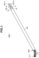
- Fig. 1 illustrates an example of an external configuration of a continuum robot 100 used in the present exemplary embodiment.
- the continuum robot 100 according to the present exemplary embodiment is hereinafter referred to as a "continuum robot 100-1".
- the continuum robot 100-1 illustrated in Fig. 1 includes a bendable portion 110 including a wire 1a, a wire 1b, and a wire 1c, a long portion 120, and actuators 130-1a to 130-1c (hereinafter also collectively referred to as actuators 130).
- the bendable portion 110 is a component configured to be bent three-dimensionally by driving of at least one of the wires 1a to 1c.
- the continuum robot 100-1 includes a single bendable portion (the bendable portion 110) configured to be bent three-dimensionally is assumed and described.
- a distal end 111 (see Fig. 2 ) of the bendable portion 110 is provided with a small sensor coil 1111 for detecting a torsional angle ⁇ 1 indicating a torsional amount about a central axis 113 (see Fig. 3 ) of the bendable portion 110.
- the long portion 120 is a component that includes the wires 1a to 1c and is configured to be bent passively by, for example, an external force.
- the bendable portion 110 ranges from a proximal end corresponding to a front end face 1201 of the long portion 120 to the distal end 111 at which the sensor coil 1111 is provided.
- the actuators 130-1a to 130-1c are drive units that drive the wires 1a to 1c. More specifically, the actuator 130-1a drives the wire 1a, the actuator 130-1b drives the wire 1b, and the actuator 130-1c drives the wire 1c.
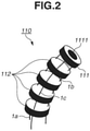
- Fig. 2 is an enlarged diagram illustrating a schematic configuration of the bendable portion 110 illustrated in Fig. 1 .
- components similar to those illustrated in Fig. 1 are denoted by the same reference numerals and the detailed descriptions thereof will be omitted.
- the wires 1a to 1c are guided by a plurality of wire guides 112 illustrated in Fig. 2 and a hole formed in the long portion 120 illustrated in Fig. 1 .
- Each of the wires 1a to 1c has one end that is connected to the distal end 111 (the wire guide provided with the sensor coil 1111) of the bendable portion 110 illustrated in Fig. 2 , and the other end that is connected to the corresponding one of the actuators 130-1a to 130-1c illustrated in Fig. 1 .
- the actuators 130-1a to 130-1c are driven in the direction of the central axis 113 of the bendable portion 110, the wires 1a to 1c are each pushed or pulled, thereby enabling the bendable portion 110 to be bent three-dimensionally.
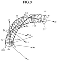
- Fig. 3 illustrates an example of a model for the bendable portion 110 illustrated in Fig. 1 . More specifically, Fig. 3 is a diagram for deriving a model in which the wires 1a to 1c move in a spiral along the central axis 113 of the bendable portion 110 of the continuum robot 100-1.
- the model illustrated in Fig. 3 is used to consider a twist of the bendable portion 110 of the continuum robot 100-1, and a continuum robot control device 200 (see Fig. 5 ) that provides a control input for matching the attitude of the bendable portion 110 with a target attitude is designed.
- each of the wires 1a to 1c in the bendable portion 110 is indicated by a thick solid line, and the central axis 113 of the bendable portion 110 is indicated by a dashed-dotted line.
- each cross section obtained by virtually dividing the bendable portion 110 into m 1 minute sections in the longitudinal direction of the bendable portion 110, i.e., the direction of the central axis 113 is indicated by a thin solid line (wherein m 1 is the number of minute sections).
- the center of the front end face 1201 of the long portion 120 corresponding to the proximal end of the bendable portion 110 illustrated in Fig. 1 is defined as an origin O 1 .
- a Zi-axis is provided in the direction of the central axis 113 in the front end face 1201
- an X 1 -axis is provided in the direction from the origin O 1 to the position of the wire 1a in the front end face 1201
- a Y 1 -axis is provided in the direction orthogonal to each of the X 1 -axis and the Zi-axis.
- a Z 2 -axis is provided in the direction of the central axis 113 at the distal end 111 of the bendable portion 110, and an angle formed between the Zi-axis and the Z 2 -axis is defined as the bending angle ⁇ 1 of the bendable portion 110.
- a Wi-axis is provided in the direction from the origin O 1 to the center of the distal end 111 within an X 1 -Y 1 plane, and an angle formed between the X 1 -axis and the Wi-axis is defined as the turning angle ⁇ 1 of the bendable portion 110.
- the wires 1a to 1c move on a plane parallel to a W 1 -Z 1 plane. Accordingly, the length of each of the wires 1a to 1c can be easily calculated even when the wires 1a to 1c are treated as a continuum.
- each of the wires 1a to 1c moves in a spiral along the central axis 113 in the longitudinal direction of the bendable portion 110. Accordingly, if the length of each of the wires 1a to 1c is calculated while the wires 1a to 1c are treated as a continuum, complicated calculations become involved, which leads to an increase in the calculation load on the continuum robot control device 200. Therefore, in the present exemplary embodiment, a discretization is performed by virtually dividing the bendable portion 110 into a plurality of minute sections in the longitudinal direction (the direction of the central axis 113) as illustrated in Fig. 3 .
- each of the wires 1a to 1c is approximated to a linear shape to calculate the length of each of the wires 1a to 1c.
- a Zij-axis is provided in the direction of the distal end 111 with a center on the front end face 1201 side as an origin Oij
- an Xij-axis is provided on a plane that is orthogonal to the Zij-axis and is flush with the Xi-axis
- a Yij-axis is provided in the direction orthogonal to each of the Xij-axis and the Zij-axis.
- a W 1,j -axis is provided on the line of intersection of an Xij-Yij plane and the W 1 -Z 1 plane.
- Fig. 4 illustrates an example of a model for the j-th minute section illustrated in the Fig. 3 .
- an intersection between the Wij-axis and a Wij+i-axis is defined as a point Tij.
- an angle formed between a vector connecting the origin O 1,j and the point T 1,j and a vector connecting an origin Oij+i and the point T 1,j is defined as the bending angle ⁇ 1,j of the j-th minute section as illustrated in Fig. 4 .
- Fig. 4 an angle formed between a vector connecting the origin O 1,j and the point T 1,j and a vector connecting an origin Oij+i and the point T 1,j is defined as the bending angle ⁇ 1,j of the j-th minute section as illustrated in Fig. 4 .
- an intersection between the wire 1a and a plane closer to the front end face 1201 in the j-th minute section is defined as a point P 1a1,j
- an angle formed between the Xij-axis and a vector connecting the origin O 1,j and the point P 1a1,j is defined as a wire torsional angle (also referred to as a "torsional angle") ⁇ 1,j
- a wire torsional angle also referred to as a "torsional angle”
- ⁇ 1,j an intersection between the wire 1a and a plane closer to the distal end 111 in the j-th minute section
- a projected point on the Xij-Yij plane at the point Piaij+i is defined as a point P' 1a1,j
- an angle formed between the Xij-axis and a vector connecting the origin O 1,j and the point P' 1a1,j is defined as a torsional angle ⁇ 1,j+1 of the (j+1)-th minute section.
- Each of the wires 1a to 1c has a linear shape in each minute section.
- a length l 1a1,j of the wire 1a that passes through the j-th minute section of the bendable portion 110 is derived. Based on Assumption 1, the length l 1a1,j of the wire 1a corresponds to the length of a line segment P 1a1,j -P 1a1,j+1 illustrated in Fig. 4 .
- a vector p 1a1,j from the origin O 1,j to the point P 1a1,j is represented by the following expression (1).
- p 1 a 1 , j r g cos ⁇ 1 , j r g sin ⁇ 1 , j 0 T
- a vector p' 1a1,j from the origin O 1,j to the point P' 1a1,j is represented by the following expression (2).
- p ⁇ 1 a 1 , j r g cos ⁇ 1 , j + 1 r g sin ⁇ 1 , j + 1 0 T
- a vector t 1,j from the origin O 1,j to the point T 1,j is represented by the following expression (3).
- t 1 , j ⁇ l 1 , j ⁇ 1 , j cos ⁇ 1 , j ⁇ l 1 , j ⁇ 1 , j sin ⁇ 1 , j 0 T
- the length ⁇ l 1,j of the j-th minute section is represented by the following expression (4).
- ⁇ l 1 , j l 1 0 m 1
- the bending angle ⁇ 1,j , a turning angle ⁇ 1,j , and the torsional angle ⁇ 1,j of the j-th minute section are respectively represented by the following expressions (5), (6), and (7) using the bending angle ⁇ 1 , the turning angle ⁇ 1 , and the torsional angle ⁇ 1 of the bendable portion 110.
- the point P 1a1,j+1 is a point obtained by rotating the point P' 1a1,j about an axis that passes through the point T 1,j and is orthogonal to a Wij-Zij plane, by the amount corresponding to the bending angle ⁇ 1,j .
- a rotation matrix for rotating the point about the Zij-axis by the amount corresponding to the turning angle ⁇ 1,j with the origin Oij+i as a center is represented by Rz( ⁇ 1,j ) and a rotation matrix for rotating the point about the Yij-axis by the amount corresponding to the bending angle ⁇ 1,j is represented by Ry( ⁇ 1,j )
- a vector p 1a1,j+1 from the origin O 1,j to the point P 1a1,j+1 is represented by the following expression (8) using the vector p' 1a1,j and the vector t 1,j .
- the matrix Rz( ⁇ 1,j ) and the matrix Ry( ⁇ 1,j ) are obtained by the following expressions (9) and (10), respectively.
- R z ⁇ 1 , j cos ⁇ 1 , j ⁇ sin ⁇ 1 , j 0 sin ⁇ 1 , j cos ⁇ 1 , j 0 0 0 1
- R y ⁇ 1 , j cos ⁇ 1 , j 0 sin ⁇ 1 , j 0 1 0 ⁇ sin ⁇ 1 , j 0 cos ⁇ 1 , j
- the length l 1a1 of the wire 1a in the bendable portion 110 (i.e., the overall length of the wire 1a that passes through the bendable portion 110) is the sum of the lengths of the wire 1a in the respective minute sections of the bendable portion 110. Accordingly, the length l 1a1 of the wire 1a in the bendable portion 110 is represented by the following expression (12).
- a vector p' 1b1,j from the origin O 1,j to a projected point P' 1b1,j and a vector p' 1c1,j from the origin O 1,j to a projected point P' 1c1,j are represented by the following expressions (15) and (16), respectively.
- p ⁇ 1 b 1 , j r g cos ⁇ 1 , j + 1 + 2 ⁇ 3 r g sin ⁇ 1 , j + 1 + 2 ⁇ 3 0 T
- p ⁇ 1 c 1 , j r g cos ⁇ 1 , j + 1 + 4 ⁇ 3 r g sin ⁇ 1 , j + 1 + 4 ⁇ 3 0 T
- a vector p 1b1,j+1 from the origin O 1,j to an intersection P 1b1,j+1 between the wire 1b and a plane closer to the distal end 111 in the j-th minute section, and a vector p 1c1,j+1 from the origin O 1,j to an intersection Picij+i between the wire 1c and a plane closer to the distal end 111 in the j-th minute section are represented by the following expressions (17) and (18), respectively.
- the length l 1b1 of the wire 1b in the bendable portion 110 and the length l 1c1 of the wire 1c in the bendable portion 110 are represented by the following expressions (19) and (20), respectively.
- Fig. 5 is a block diagram illustrating an example of a functional configuration of a continuum robot control system 10 according to the present exemplary embodiment.
- the continuum robot control system 10 according to the present exemplary embodiment is hereinafter referred to as a "continuum robot control system 10-1".
- Fig. 5 components similar to those illustrated in Figs. 1 and 3 are denoted by the same reference numerals and the detailed descriptions thereof will be omitted.
- the continuum robot control system 10-1 includes the continuum robot 100 (more specifically, the continuum robot 100-1 illustrated in Fig. 1 ), the continuum robot control device 200, and an input device 310. More specifically, the continuum robot control system 10-1 is a control system for the continuum robot 100-1 including the bendable portion 110 configured to be bent by the driving of the wires 1a to 1c, and the actuators (drive units) 130-1a to 130-1c configured to drive the wires 1a to 1c, respectively.
- the input device 310 inputs information to the continuum robot control device 200, and includes an input unit 311 and a magnetic sensor unit 312.
- the input unit 311 is a component that inputs the bending angle (target bending angle) ⁇ 1 of the bendable portion 110 and the turning angle (target turning angle) ⁇ 1 of the bendable portion 110 to the continuum robot control device 200.
- the magnetic sensor unit 312 is a component that measures the torsional angle ⁇ 1 about the central axis 113 of the bendable portion 110 based on the intensity and attitude of a magnetic field obtained by the sensor coil 1111 provided at the distal end 111 of the bendable portion 110, and inputs the measured torsional angle as the torsional angle ⁇ 1 of the bendable portion 110 to the continuum robot control device 200.
- the magnetic sensor unit 312 and the sensor coil 1111 constitute a "torsional angle acquisition unit" that acquires the torsional angle ⁇ 1 of the bendable portion 110.
- the continuum robot control device 200 controls the continuum robot 100 (more specifically, the continuum robot 100-1 illustrated in Fig. 1 ) based on the information input from the input device 310, and includes a kinematics calculation unit 211 and a position control unit 221.
- the kinematics calculation unit 211 is a component that calculates the lengths l 1a1 , l 1b1 , and l 1c1 of the wires 1a, 1b, and 1c in the bendable portion 110, respectively based on the bending angle ⁇ 1 , the turning angle ⁇ 1 , and the torsional angle ⁇ 1 of the bendable portion 110 that are input from the input device 310.
- the position control unit 221 is a component that outputs drive commands f 1a , f 1b , and f 1c to the actuators 130-1a, 130-1b, and 130-1c in the continuum robot 100-1, respectively so that the lengths of the wires 1a, 1b, and 1c in the bendable portion 110 match the lengths l 1a1 , l 1b1 , and l 1c1 , respectively.
- the position control unit 221 controls the actuators 130-1a to 130-1c to drive the wires 1a to 1c, based on the lengths l 1a1 to l 1c1 of the wires 1a to 1c in the bendable portion 110, respectively, which are obtained by the kinematics calculation unit 211.
- Fig. 6 is a block diagram illustrating an example of a functional configuration of the kinematics calculation unit 211 illustrated in Fig. 5 according to the present exemplary embodiment.
- components similar to those illustrated in Fig. 5 are denoted by the same reference numerals and the detailed descriptions thereof will be omitted.
- Fig. 6 illustrates a configuration example in which only the length l 1a1 of the wire 1a, among those of the wires 1a to 1c for bending the bendable portion 110, is calculated.
- components similar to those for the wire 1a are also included for the wires 1b and 1c.
- the kinematics calculation unit 211 includes an angle calculation unit 610, a wire length calculation unit 620, and an addition unit 630.
- the angle calculation unit 610 calculates, for each of a plurality of minute sections obtained by dividing the bendable portion 110 in the longitudinal direction as described above with reference to Fig. 3 , a bending angle ⁇ , a turning angle ⁇ , and a torsional angle ⁇ of the minute section, based on the bending angle ⁇ 1 , the turning angle ⁇ 1 , and the torsional angle ⁇ 1 of the bendable portion 110 that are input from the input device 310. More specifically, Fig.
- the angle calculation unit 610 calculates the bending angle ⁇ 1,j , the turning angle ⁇ 1,j , and the torsional angle ⁇ 1,j of each minute section by using the expressions (5) to (7).
- the wire length calculation unit 620 calculates, for each of the plurality of minute sections obtained by dividing the bendable portion 110 in the longitudinal direction, the length l 1a1 (l 1a1,j-1 , l 1a1,j , l 1a1,j+1 , and ⁇ ) of the wire 1a in the minute section, based on the bending angle ⁇ , the turning angle ⁇ , and the torsional angle ⁇ of the minute section.
- the wire length calculation unit 620 calculates the lengths l 1a1,j-1 , l 1a1,j , l 1a1,j+1 , and ⁇ of the wire 1a in the respective minute sections based on the bending angle ⁇ , the turning angle ⁇ , and the torsional angle ⁇ of each of the minute sections, which are obtained by the angle calculation unit 610.
- the wire length calculation unit 620 illustrated in Fig. 6 includes a plurality of wire length calculators 621 each corresponding to a different one of the plurality of minute sections.
- the wire length calculation unit 620 calculates the length l 1a1,j of the wire 1a in the j-th minute section by using the expressions (1) to (4) and the expressions (8) to (11).
- the addition unit 630 calculates the length l 1a1 of the wire 1a in the bendable portion 110 by adding the lengths l 1a1,j-1 , l 1a1,j , l 1a1,j+1 , and ⁇ of the wire 1a in the respective minute sections, which are obtained by the wire length calculation unit 620.
- the addition unit 630 calculates the length l 1a1 of the wire 1a in the bendable portion 110 (i.e., the length of the wire 1a that passes through the bendable portion 110) by using the expression (12).
- a simulation has been performed using the model for the continuum robot 100-1 derived in the above-described ⁇ 1-1. Modeling>, and using the continuum robot control system 10-1 presented in the above-described ⁇ 1-2. Control System>.
- the number m 1 of minute sections is 20
- the length l 10 of the bendable portion 110 is 0.03 m
- the distance r g from the central axis 113 of the bendable portion 110 to each of the wires 1a to 1c is 0.002 m.
- Fig. 7 illustrates a result of the simulation using the continuum robot control system 10-1 according to the present exemplary embodiment. More specifically, Fig. 7 illustrates a model for the bendable portion 110 assuming that the bending angle ⁇ 1 of the bendable portion 110 is 90 degrees, the turning angle ⁇ 1 of the bendable portion 110 is 0 degree, and the torsional angle ⁇ 1 of the bendable portion 110 is 180 degrees.
- the shape of a wire 710 (hereinafter referred to as the "wire 710 according to the present exemplary embodiment") derived using the model for the continuum robot control system 10-1 according to the present exemplary embodiment is indicated by a solid line.
- the shape of a wire 720 (hereinafter referred to as the "wire 720 according to Japanese Patent Application Laid-Open No. 2019-122491 ") derived using a calculation method according to Japanese Patent Application Laid-Open No. 2019-122491 is indicated by a broken line
- the shape of a wire 730 (hereinafter referred to as the "wire 730 not considering a twist”) derived without taking into consideration a twist is indicated by a dotted line.
- a point P 1a1,0 which is the position of the wire 1a at the front end face 1201 corresponding to the proximal end of the bendable portion 110, is located on the inner periphery of the bendable portion 110.
- a point P 1a1,m which is the position of the wire 1a at the distal end 111 of the bendable portion 110, is located on the outer periphery of the bendable portion 110.
- the wire 710 moves in a spiral from the point P 1a1,0 to the point P 1a1,m along the central axis 113 of the bendable portion 110.
- the position of the wire 1a at the front end face 1201 corresponding to the proximal end of the bendable portion 110 corresponds to a point P" 1a1,0 obtained by rotating the point P 1a1,0 about the Zi-axis by the torsional angle ⁇ 1 of 180 degrees.
- the wire 720 according to Japanese Patent Application Laid-Open No.
- the wire 730 not considering a twist the position of the wire 1a at the distal end 111 of the bendable portion 110 corresponds to a point P" 1a1,m obtained by rotating the point P 1a1,m about a Z 1,m+1 -axis by minus 180 degrees. Accordingly, as indicated by the dotted line in Fig. 7 , the wire 730 not considering a twist moves from the point P 1a1,0 to the point P" 1a1,m on the inner periphery of the bendable portion 110 along the central axis 113 of the bendable portion 110.
- Fig. 8 is a graph illustrating the result of the simulation using the continuum robot control system 10 according to the present exemplary embodiment. More specifically, Fig. 8 illustrates how the length l 1a1 of the wire 1a changes when the bending angle ⁇ 1 of the bendable portion 110 is 90 degrees, the turning angle ⁇ 1 of the bendable portion 110 is 0 degree, and the torsional angle ⁇ 1 of the bendable portion 110 is changed from 0 to 180 degrees.
- the length l 1a1 of the wire 710 according to the present exemplary embodiment illustrated in Fig. 7 is indicated by a solid line
- a length l 1a1_pr of the wire 720 according to Japanese Patent Application Laid-Open No. 2019-122491 illustrated in Fig. 7 is indicated by a broken line
- a length l 1a1_wo of the wire 730 not considering a twist illustrated in Fig. 7 is indicated by a dotted line.
- the length l 1a1 of the wire 710 according to the present exemplary embodiment increases as the torsional angle ⁇ 1 increases because the pitch of the spiral decreases.
- the wire 720 according to Japanese Patent Application Laid-Open No. 2019-122491 moves on the outer peripheral of the bendable portion 110 more than the wire 710 according to the present exemplary embodiment, and thus the length l 1a1_pr of the wire 720 according to Japanese Patent Application Laid-Open No. 2019-122491 is longer than the length l 1a1 of the wire 710 according to the present exemplary embodiment. Furthermore, as indicated by the dotted line in Fig.
- the wire 730 not considering a twist moves on the inner periphery of the bendable portion 110 regardless of the torsional angle ⁇ 1 ., and thus the length l 1a1_wo of the wire 730 is shorter than the length l 1a1 of the wire 710 according to the present exemplary embodiment.
- the wire length calculation unit 620 calculates the lengths l 1a1,j-1 , l 1a1,j , l 1a1,j+1 , and ⁇ of the wire 1a in the respective plurality of minute sections obtained by dividing the bendable portion 110 in the longitudinal direction, based on the bending angle ⁇ , the turning angle ⁇ , and the torsional angle ⁇ of each of the plurality of minute sections.
- the addition unit 630 calculates the length l 1a1 of the wire 1a in the bendable portion 110 by adding the lengths l 1a1,j-1 , l 1a1,j , l 1a1,j+1 , and ⁇ of the wire 1a in the respective minute sections, which are obtained by the wire length calculation unit 620.
- the length l 1a1 of the wire 1a in the bendable portion 110 can be accurately calculated. Processing similar to that for the wire 1a is performed on the other wires 1b and 1c for bending the bendable portion 110, thereby making it possible to accurately calculate the length l 1b1 of the wire 1b and the length l 1c1 of the wire 1c in the bendable portion 110 even when the bendable portion 110 is twisted. As a result, an improvement in the control performance of the continuum robot 100-1 can be achieved.
- the above-described configuration of the continuum robot control system 10-1 according to the present exemplary embodiment makes it possible to reduce an error between the target attitude of the bendable portion 110 and the actual attitude of the bendable portion 110 even when the bendable portion 110 is twisted, which leads to an improvement in the safety and operability of the bendable portion 110.
- the configuration in which the continuum robot 100-1 includes the single bendable portion 110 configured to be bent three-dimensionally has been assumed and described
- a configuration in which the continuum robot 100 includes a plurality of the bendable portions 110 two bendable portions 110-1 and 110-2 will be assumed and described.
- Fig. 9 illustrates an example of an external configuration of the continuum robot 100 used in the present exemplary embodiment.
- the continuum robot 100 according to the present exemplary embodiment is hereinafter referred to as a "continuum robot 100-2".
- Fig. 9 components similar to those illustrated in Figs. 1 and 2 are denoted by the same reference numerals.
- Fig. 9 illustrates only the two bendable portions 110-1 and 110-2 in the continuum robot 100-2 used in the present exemplary embodiment.
- the continuum robot 100-2 used in the present exemplary embodiment includes not only the two bendable portions 110-1 and 110-2 illustrated in Fig. 9 , but also components corresponding to the long portion 120 and the actuators 130 illustrated in Fig. 1 .
- the continuum robot 100-2 illustrated in Fig. 9 includes the first bendable portion 110-1 and the second bendable portion 110-2 as a plurality of bendable portions arranged in series.
- the first bendable portion 110-1 corresponds to the bendable portion 110 illustrated in Figs. 1 and 2 .
- the second bendable portion 110-2 is provided at a position farther from the actuators 130 serving as drive units than the first bendable portion 110-1. While in the present exemplary embodiment, the example where two bendable portions, i.e., the first bendable portion 110-1 and the second bendable portion 110-2 are included as the plurality of bendable portions is illustrated, a configuration including three or more bendable portions can also be used.
- the first bendable portion 110-1 is a component configured to be bent three-dimensionally by the driving of at least one of the wires 1a to 1c.
- the distal end 111 of the first bendable portion 110-1 is provided with the small sensor coil 1111 for detecting the torsional angle ⁇ 1 indicating the torsional amount about the central axis 113 of the first bendable portion 110-1.
- the wires 1a to 1c illustrated in Fig. 9 are guided by the plurality of wire guides 112 illustrated in Fig. 9 and the hole formed in the long portion 120 illustrated in Fig. 1 .
- it is assumed that the first bendable portion 110-1 ranges from the proximal end corresponding to the front end face 1201 of the long portion 120 illustrated in Fig.
- the wires 1a to 1c illustrated in Fig. 9 each have one end that is connected to the distal end 111 (the wire guide provided with the sensor coil 1111) of the first bendable portion 110-1 illustrated in Fig. 9 , and the other end that is connected to the corresponding one of the actuators 130-1a to 130-1c illustrated in Fig. 1 .
- the wires 1a to 1c are each pushed or pulled, thereby enabling the first bendable portion 110-1 to be bent three-dimensionally.
- the second bendable portion 110-2 is a component configured to be bent three-dimensionally by driving of at least one of wires 2a, 2b, and 2c.
- a distal end 121 of the second bendable portion 110-2 is provided with a small sensor coil 1211 for detecting a torsional angle ⁇ 2 indicating a torsional amount about a central axis of the second bendable portion 110-1.
- the wires 2a to 2c illustrated in Fig. 9 are guided by a plurality of wire guides 122 illustrated in Fig. 9 , the distal end 111 and the plurality of wire guides 112 of the first bendable portion 110-1, and the hole formed in the long portion 120 illustrated in Fig. 1 .
- the distal end 111 and the plurality of wire guides 112 of the first bendable portion 110-1 are provided with not only holes for guiding the wires 1a to 1c, but also holes for guiding the wires 2a to 2c.
- the second bendable portion 110-2 ranges from the proximal end corresponding to the distal end 111 of the first bendable portion 110-1 illustrated in Fig. 9 to the distal end 121 provided with the sensor coil 1211.
- the wires 2a to 2c illustrated in Fig. 9 each have one end that is connected to the distal end 121 (the wire guide provided with the sensor coil 1211) of the second bendable portion 110-2 illustrated in Fig.
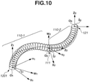
- Fig. 10 illustrates an example of a model for each of the first bendable portion 110-1 and the second bendable portion 110-2 illustrated in Fig. 9 .
- components similar to those illustrated in Figs. 3 and 9 are denoted by the same reference numerals and the detailed descriptions thereof will be omitted.
- the distal end 111 of the first bendable portion 110-1 is defined as an origin O 2
- the Z 2 -axis is provided in the normal direction to the distal end 111
- an X 2 -axis is provided in a circumferential direction
- a Y 2 -axis is provided in the direction orthogonal to each of the X 2 -axis and the Z 2 -axis.
- a W 2 -axis is provided in the direction from the origin O 2 to a central point O 3 of the distal end 121 of the second bendable portion 110-2 within an X 2 -Y 2 plane, and an angle formed between the X 2 -axis and the W 2 -axis is defined as a turning angle - ⁇ 2 of the second bendable portion 110-2.
- the symbol " ⁇ " used for the turning angle ⁇ 2 of the second bendable portion 110-2 indicates a relative coordinate system.
- the reference symbol ( ⁇ ) indicating a relative coordinate system is added to the top of each element.
- the reference symbol ( ⁇ ) is added to the side of each element, for example, like the turning angle " ⁇ 2 ", because of the format.
- the reference symbol ( ⁇ ) added to the side of each element indicates the same meaning as the reference symbol ( ⁇ ) added to the top of each element.
- the central point O 3 of the distal end 121 of the second bendable portion 110-2 is defined as an origin, and a Z 3 -axis is provided in the normal direction to the distal end 121. Furthermore, an angle formed between the Z 2 -axis and the Z 3 -axis is defined as a relative bending angle ⁇ 2 of the second bendable portion 110-2 relative to the first bendable portion 110-1.
- a length l 2a1 of a portion that passes through the first bendable portion 110-1 and a length l 2a2 of a portion that passes through the second bendable portion 110-2 are calculated using a method similar to that used in the first exemplary embodiment.
- an overall length l 2a of the wire 2a in the first bendable portion 110-1 and the second bendable portion 110-2 is calculated by adding the length l 2a1 and the length l 2a2 .
- the length l 2a1 of the wire 2a in the first bendable portion 110-1 (i.e., the length of the wire 2a that passes through the first bendable portion 110-1) is derived.
- a length l 2a1,j of the wire 2a in the j-th minute section of the first bendable portion 110-1 corresponds to the difference between a vector p 2a1,j from the origin O 1,j to the front end face 1201 corresponding to the proximal end and a vector p 2a1,j+1 from the origin O 1,j to the distal end 111.
- the length l 2a1,j is represented by the following expression (21).
- l 2 a 1 , j p 2 a 1 , j + 1 ⁇ p 2 a 1 , j
- the vector p 2a1,j is represented by the following expression (22), similarly to the expression (1).
- p 2 a 1 , j r g cos ⁇ 1 , j + ⁇ 2 r g sin ⁇ 1 , j + ⁇ 2 0 T
- the vector p 2a1,j+1 is represented by the following expression (23) using a vector p' 2a1,j from the origin O 1,j to a point P' 2a1,j obtained by projecting a point P 2a1,j+1 onto the Xij-Yij plane.
- p 2 a 1 , j + 1 R z ⁇ 1 , j R y ⁇ 1 , j R z ⁇ ⁇ 1 , j p ⁇ 2 a 1 , j ⁇ t 1 , j + t 1 , j
- the vector p' 2a1,j is represented by the following expression (24).
- p ⁇ 2 a 1 , j r g cos ⁇ 1 , j + 1 + ⁇ 2 r g sin ⁇ 1 , j + 1 + ⁇ 2 0 T
- the length l 2a1 is obtained by adding the lengths l 2a1,j in all minute sections by using the following expression (25).
- the length l 2a2 of the wire 2a in the second bendable portion 110-2 (i.e., the length of the wire 2a that passes through the second bendable portion 110-2) is derived.
- the length l 2a2,k is represented by the following expression (26), similarly to the expression (11).
- l 2 a 2 , k p 2 a 2 , k + 1 ⁇ p 2 a 2 , k
- the vector p 2a2,k is represented by the following expression (27) using a torsional angle ⁇ 2,k of the k-th minute section.
- p 2 a 2 , k r g cos ⁇ 2 , k + ⁇ 2 r g sin ⁇ 2 , k + ⁇ 2 0 T
- the vector p 2a2,k+1 is represented by the following expression (28) using a bending angle ⁇ 2,k and a vector p' 2a2,k from the origin O 2,k to a point P' 2a2,k obtained by projecting a point P 2a2,k+1 onto an X 2,k -Y 2,k plane.
- p 2 a 2 , k + 1 R z ⁇ 2 , k R y ⁇ ⁇ ⁇ 2 , k R z ⁇ ⁇ 2 , k p ⁇ 2 a 2 , k ⁇ t 2 , k + t 2 , k
- the vector p' 2a2,k is represented by the following expression (29).
- p ⁇ 2 a 2 , k r g cos ⁇ 2 , k + 1 + ⁇ 2 r g sin ⁇ 2 , k + 1 + ⁇ 2 0 T
- t 2,k , ⁇ l 2,k , ⁇ 2,k , - ⁇ 2,k and ⁇ 2,k are obtained by using the following expressions (30) to (34), respectively, in the present exemplary embodiment.
- the length l 2a2 is obtained by adding the lengths l 2a2,k in all minute sections by using the following expression (35).
- the length of a portion that passes through the first bendable portion 110-1 and the length of a portion that passes through the second bendable portion 110-2 are calculated separately and added together, so that the overall length l 2b of the wire 2b and the overall length l 2c of the wire 2c in the first bendable portion 110-1 and the second bendable portion 110-2 can be calculated.
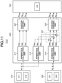
- Fig. 11 is a block diagram illustrating an example of a functional configuration of the continuum robot control system 10 according to the present exemplary embodiment.
- the continuum robot control system 10 according to the present exemplary embodiment is hereinafter referred to as a "continuum robot control system 10-2".
- Fig. 11 components similar to those illustrated in Figs. 5 and 10 are denoted by the same reference numerals and the detailed descriptions thereof will be omitted.
- the continuum robot control system 10-2 includes the continuum robot 100 (more specifically, the continuum robot 100-2 illustrated in Fig. 9 ), the continuum robot control device 200, the input device 310, and an input device 320. More specifically, the continuum robot control system 10-2 is a control system for the continuum robot 100-2 including the first bendable portion 110-1 configured to be bent by the driving of the wires 1a to 1c, the second bendable portion 110-2 configured to be bent by the driving of the wires 2a to 2c, the actuators (drive units) 130-1a to 130-1c configured to drive the wires 1a to 1c, respectively, and the actuators (drive units) 130-2a to 130-2c configured to drive the wires 2a to 2c, respectively.
- the continuum robot control system 10-2 illustrated in Fig. 11 has a configuration in which the input device 320 is added to the continuum robot control system 10-1 illustrated in Fig. 5 .
- the input unit 311 of the input device 310 is a component that inputs the bending angle (target bending angle) ⁇ 1 of the first bendable portion 110-1 and the turning angle (target turning angle) ⁇ 1 of the first bendable portion 110-1 to the continuum robot control device 200.
- the magnetic sensor unit 312 of the input device 310 is a component that measures the torsional angle ⁇ 1 about the central axis 113 of the first bendable portion 110-1 based on the intensity and attitude of a magnetic field obtained by the sensor coil 1111 provided at the distal end 111 of the first bendable portion 110-1, and inputs the measured torsional angle as the torsional angle ⁇ 1 of the first bendable portion 110-1 to the continuum robot control device 200.
- the magnetic sensor unit 312 and the sensor coil 1111 constitute the "torsional angle acquisition unit" that acquires the torsional angle ⁇ 1 of the bendable portion 110.
- the input device 320 inputs information to the continuum robot control device 200, and includes an input unit 321 and a magnetic sensor unit 322.
- the input unit 321 is a component that inputs a bending angle (target bending angle) ⁇ 2 of the second bendable portion 110-2 and a turning angle (target turning angle) ⁇ 2 of the second bendable portion 110-2 to the continuum robot control device 200.
- the magnetic sensor unit 322 is a component that measures the torsional angle ⁇ 2 about the central axis 113 of the second bendable portion 110-2 based on the intensity and attitude of a magnetic field obtained by the sensor coil 1211 provided at the distal end 121 of the second bendable portion 110-2, and inputs the measured torsional angle as the torsional angle ⁇ 2 of the second bendable portion 110-2 to the continuum robot control device 200.
- the magnetic sensor unit 322 and the sensor coil 1211 constitute the "torsional angle acquisition unit" that acquires the torsional angle ⁇ 2 of the bendable portion 110.
- the continuum robot control device 200 illustrated in Fig. 11 controls the continuum robot 100 (more specifically, the continuum robot 100-2 illustrated in Fig. 9 ) based on the information input from the input device 310 and the input device 320.
- the continuum robot control device 200 illustrated in Fig. 11 includes kinematics calculation units 211 to 213, position control units 221 to 222, and an addition unit 231.
- the kinematics calculation unit 211 and the position control unit 221 illustrated in Fig. 11 perform processing similar to that performed by the kinematics calculation unit 211 and the position control unit 221 illustrated in Fig. 5 , respectively, and thus the descriptions thereof will be omitted.
- the kinematics calculation unit 212 is a component that calculates lengths l 2a1 , l 2b1 , and l 2c1 of the wires 2a, 2b, and 2c in the first bendable portion 110-1 by using the expression (25), respectively, based on the bending angle ⁇ 1 , the turning angle ⁇ 1 , and the torsional angle ⁇ 1 of the first bendable portion 110-1 that are information input from the input device 310.
- the kinematics calculation unit 213 is a component that calculates lengths l 2a2 , l 2b2 , and l 2c2 of the wires 2a, 2b, and 2c in the second bendable portion 110-2 by using the expression (35), respectively, based on the bending angle ⁇ 2 , the turning angle ⁇ 2 , and the torsional angle ⁇ 2 of the second bendable portion 110-2 that are information input from the input device 320.
- the addition unit 231 calculates the overall lengths l 2a to l 2c of the wires 2a to 2c in the first bendable portion 110-1 and the second bendable portion 110-2, respectively by adding the lengths l 2a1 , l 2b1 , and l 2c1 of the wires 2a, 2b, and 2c in the first bendable portion 110-1 calculated by the kinematics calculation unit 212 and the lengths l 2a2 , l 2b2 , and l 2c2 of the wires 2a, 2b, and 2c in the second bendable portion 110-2 calculated by the kinematics calculation unit 213, respectively.
- the position control unit 222 is a component that outputs drive commands f 2a , f 2b , and f 2c to the actuators 130-2a, 130-2b, and 130-2c of the continuum robot 100-2, respectively so that the lengths of the wires 2a, 2b, and 2c in the second bendable portion 110-2 match the lengths ha, hb, and l 2c calculated by the addition unit 231, respectively.
- the position control unit 222 controls the actuators 130-2a to 130-2c to drive the wires 2a to 2c, respectively, based on the lengths l 2a1 , hbi, and l 2c1 of the wires 2a, 2b, and 2c in the first bendable portion 110-1 and the lengths l 2a2 , l 2b2 , and l 2c2 of the wires 2a, 2b, and 2c in the second bendable portion 110-2, which are obtained by the kinematics calculation unit 212 and the kinematics calculation unit 213.
- the length of each wire in each of the plurality of bendable portions 110 can be accurately calculated.
- an improvement in the control performance of the continuum robot 100-2 can be achieved.
- a control system for the continuum robot 100 in which the distribution of each of the bending angle ⁇ , the turning angle ⁇ , and the torsional angle ⁇ of the bendable portion 110 is not uniform is applied.
- the torsional angle ⁇ of each minute section is derived assuming that the torsional angle ⁇ indicating the torsional amount of the bendable portion 110 is uniformly distributed.
- the bending angle ⁇ of each minute section is derived assuming that the bendable portion 110 is bent with a constant curvature.
- a path in an organ such as a large intestine or a lung, is bent in a complicated manner. Accordingly, the above-described assumptions are not always satisfied in the bendable portion 110 that enters into such an organ.
- the control system first stores the bending angle ⁇ , the turning angle ⁇ , and the torsional angle ⁇ of when the distal end 111 of the bendable portion 110 of the continuum robot 100 passes through a certain point on a narrow space. Then, when the minute section of the bendable portion 110 reaches the point, the stored angles are read out and used to calculate the length of each wire in the bendable portion 110.
- Fig. 12 illustrates an example of an external configuration of the continuum robot control system 10 according to the present exemplary embodiment.
- the continuum robot control system 10 according to the present exemplary embodiment is hereinafter referred to as a "continuum robot control system 10-3".
- Fig. 12 components similar to those illustrated in Fig. 1 are denoted by the same reference numerals and the detailed descriptions thereof will be omitted.
- the continuum robot control system 10-3 illustrated in Fig. 12 includes the bendable portion 110, the long portion 120, an actuator/control system built-in box 1210, a direct-acting guide mechanism portion 1220, and a position sensor portion 1230.
- the actuator/control system built-in box 1210 is a component that incorporates, for example, the actuators 130-1a to 130-1c illustrated in Fig. 1 , and the continuum robot control device 200 and the input device 310 illustrated in Fig. 5 .
- the direct-acting guide mechanism portion 1220 is a component that guides the actuator/control system built-in box 1210, which is provided with the long portion 120 and the bendable portion 110, in a direct-acting manner. More specifically, the actuator/control system built-in box 1210 moves forward or backward in the longitudinal direction of the bendable portion 110.
- the position sensor portion 1230 detects a position z b in the forward/backward direction of the bendable portion 110 of the continuum robot 100. More specifically, the position sensor portion 1230 detects a displacement z b from an initial position of the bendable portion 110.
- the continuum robot control system 10-3 according to the present exemplary embodiment is similar to the continuum robot control system 10-1 according to the first exemplary embodiment illustrated in Fig. 5 .
- Fig. 13 is a block diagram illustrating an example of a functional configuration of the kinematics calculation unit 211 illustrated in Fig. 5 according to the present exemplary embodiment.
- components similar to those illustrated in Fig. 6 are denoted by the same reference numerals and the detailed descriptions thereof will be omitted.
- the kinematics calculation unit 211 according to the present exemplary embodiment illustrated in Fig. 13 differs from the kinematics calculation unit 211 according to the first exemplary embodiment illustrated in Fig. 5 in that the displacement z b from the initial position of the bendable portion 110 detected by the position sensor portion 1230 illustrated in Fig. 12 is additionally input to the angle calculation unit 610.
- the angle calculation unit 610 calculates, for each of a plurality of minute sections obtained by dividing the bendable portion 110 in the longitudinal direction, the bending angle ⁇ , the turning angle ⁇ , and the torsional angle ⁇ of the minute section based not only on the bending angle ⁇ 1 , the turning angle ⁇ 1 , and the torsional angle ⁇ 1 of the bendable portion 110 that are input from the input device 310, but also on the displacement z b from the initial position of the bendable portion 110 detected by the position sensor portion 1230.
- the angle calculation unit 610 acquires from the position sensor portion 1230 the displacement z b from the initial position of the bendable portion 110 and stores the acquired displacement z b , and also acquires from the input device 310 the bending angle ⁇ 1 , the turning angle ⁇ 1 , and the torsional angle ⁇ 1 of the bendable portion 110 corresponding to the displacement z b , and stores the acquired angles.
- a position z b1,j at the proximal end side of the j-th minute section of the bendable portion 110 is represented by the following expression (37).
- z b 1 , j z b ⁇ m 1 ⁇ j + 1 ⁇ l 1 , j
- the angle calculation unit 610 calculates the bending angle ⁇ 1,j , the turning angle ⁇ 1,j , and the torsional angle ⁇ 1,j of the j-th minute section of the bendable portion 110 by the following expressions (38) to (40).
- the wire length calculation unit 620 can calculate the length of the wire in each minute section based on the bending angle ⁇ , the turning angle ⁇ , and the torsional angle ⁇ of the bendable portion 110 that passes through the position z bl,j along a narrow space. Therefore, the control performance of the continuum robot 100 can be improved even when the bendable portion 110 enters into a narrow space that is bent in a complicated manner.
- the length of each wire can also be calculated by taking into consideration factors other than the external force.
- the torsional angle ⁇ 1,j is calculated by using the following expression (41) with a coefficient ⁇ 1,j corresponding to the torsional rigidity of the j-th minute section, so that the length of each wire can be calculated considering the rigidity distribution.
- ⁇ 1 , j ⁇ 1 , j ⁇ 1 m 1 j ⁇ 1
- the configuration of the continuum robot control system 10 in which the bending angle, the turning angle, and the torsional angle of the bendable portion 110 are acquired using the input unit and the magnetic sensor unit included in the input device is not limited thereto.
- a configuration in which these angles are acquired using a displacement sensor for measuring the amount of deformation of the bendable portion 110 and image information obtained by capturing an image of the shape of the bendable portion 110 may also be used.
- a configuration in which the bending angle, the turning angle, and the torsional angle of the bendable portion 110 are calculated and acquired based on the shape of a narrow space into which the bendable portion 110 enters may be used.
- the configuration where three wires for bending a single bendable portion 110 are pushed or pulled to bend the bendable portion 110 has been described
- the configuration is not limited thereto. More specifically, while in the above-described first to third exemplary embodiments, the example of the continuum robot 100 that three-dimensionally drives a single bendable portion 110 has been described, continuum robots to be bent on a plane and continuum robots with a different number of wires may also be used.
- the exemplary embodiments of the present disclosure can also be implemented by processing in which a program for implementing one or more functions according to the above-described exemplary embodiments is supplied to a system or an apparatus via a network or a storage medium, and one or more processors in a computer of the system or the apparatus read out and execute the program.
- the exemplary embodiments can also be implemented by a circuit (e.g., an application specific integrated circuit (ASIC)) for implementing one or more functions according to the above-described exemplary embodiments.
- ASIC application specific integrated circuit
- the program and a computer-readable storage medium storing the program are also included in the exemplary embodiments of the present disclosure.
- Embodiment(s) of the present disclosure can also be realized by a computer of a system or apparatus that reads out and executes computer executable instructions (e.g., one or more programs) recorded on a storage medium (which may also be referred to more fully as a 'non-transitory computer-readable storage medium') to perform the functions of one or more of the above-described embodiment(s) and/or that includes one or more circuits (e.g., application specific integrated circuit (ASIC)) for performing the functions of one or more of the above-described embodiment(s), and by a method performed by the computer of the system or apparatus by, for example, reading out and executing the computer executable instructions from the storage medium to perform the functions of one or more of the above-described embodiment(s) and/or controlling the one or more circuits to perform the functions of one or more of the above-described embodiment(s).
- computer executable instructions e.g., one or more programs
- a storage medium which may also be referred to more fully as
- the computer may comprise one or more processors (e.g., central processing unit (CPU), micro processing unit (MPU), or the like), circuitry, or combinations thereof, and may include a network of separate computers or separate processors to read out and execute the computer executable instructions.
- the computer executable instructions may be provided to the computer, for example, from a network or the storage medium.
- the storage medium may include, for example, one or more memories of a hard disk, a random-access memory (RAM), a read only memory (ROM), a storage of distributed computing systems, an optical disk (such as a compact disc (CD), digital versatile disc (DVD), or Blu-ray Disc (BD) TM ), a flash memory device, a memory card, and the like.
- a control system for a continuum robot includes a kinematics calculation unit configured to calculate a length of a wire in a bendable portion.
- the kinematics calculation unit includes a wire length calculation unit configured to calculate, for each of a plurality of minute sections obtained by dividing the bendable portion in a longitudinal direction thereof, a length of the wire in the minute section based on a bending angle, a turning angle, and a torsional angle of the minute section, and an addition unit configured to add the lengths of the wire in the plurality of minute sections obtained by the wire length calculation unit to calculate the length of the wire in the bendable portion.
Landscapes
- Engineering & Computer Science (AREA)
- Robotics (AREA)
- Mechanical Engineering (AREA)
- Health & Medical Sciences (AREA)
- General Health & Medical Sciences (AREA)
- Orthopedic Medicine & Surgery (AREA)
- Surgery (AREA)
- Life Sciences & Earth Sciences (AREA)
- Nuclear Medicine, Radiotherapy & Molecular Imaging (AREA)
- Medical Informatics (AREA)
- Molecular Biology (AREA)
- Animal Behavior & Ethology (AREA)
- Heart & Thoracic Surgery (AREA)
- Public Health (AREA)
- Veterinary Medicine (AREA)
- Biomedical Technology (AREA)
- Manipulator (AREA)
- Endoscopes (AREA)
Abstract
Description
- The present disclosure relates to a control system for a continuum robot including a bendable portion configured to be bent by driving of a wire, a control method for the continuum robot, and a program for causing a computer to function as the control system.
- In recent years, a minimally invasive medical treatment for reducing a burden on a patient and improving the quality of life (QOL) after treatment or examination has been attracting attention. Typical examples of the minimally invasive medical treatment include surgery or examination using an endoscope. For example, laparoscopic surgery enables a surgical wound to be made smaller than in the case of conventional laparotomy surgery, and is thus advantageous not only in that the hospitalization period required after surgery can be shortened, but also in that the laparoscopic surgery is cosmetically superior.
- A flexible endoscope is known as an example of the endoscope used for the minimally invasive medical treatment. Such a flexible endoscope includes an insertion portion functioning as a bendable portion formed of a bendable member. The flexible endoscope can thus reach a deep portion of the body without pressuring the tissue of a tortuous organ, such as an esophagus, a large intestine, or a lung, which makes it possible to reduce the burden on the patient. In addition, it can be expected that the burden on the patient can be further reduced, for example, by using a drive unit such as an actuator to drive the bendable portion serving as the insertion portion, and automatically controlling the attitude of the bendable portion along a path in the body. Accordingly, the search and development of a mechanism and a control method for a continuum robot that can be used as the flexible endoscope have been actively conducted.
- Many of such continuum robots adopt a method in which a drive unit such as an actuator for driving a wire is installed in a base, and the wire is used as a driving force transmission mechanism for bending the bendable portion, thereby decreasing the diameter of the bendable portion. This method enables a continuum robot to reach a deep portion of the body. However, the rigidity of the bendable portion of the continuum robot decreases as the diameter of the bendable portion is decreased. Accordingly, if the bendable portion of the continuum robot comes into contact with an inner wall of a body cavity or the like, the continuum robot (bendable portion) may be twisted about a central axis of the continuum robot. Due to the occurrence of the twist, the correspondence between the amount of driving of the wire and the attitude of the continuum robot (bendable portion) deviates from a designed value, which may lead to deterioration in the accuracy of the control performance of the continuum robot (bendable portion). In this regard, for example,
Japanese Patent Application Laid-Open No. 2019-122491 - According to the technique discussed in
Japanese Patent Application Laid-Open No. 2019-122491 Japanese Patent Application Laid-Open No. 2019-122491 Japanese Patent Application Laid-Open No. 2019-122491 - The present disclosure is directed to providing a mechanism that can achieve an improvement in the control performance of a continuum robot even when a bendable portion of the continuum robot is twisted.
- According to a first aspect of the present disclosure, there is provided a control system for a continuum robot as specified in
claims 1 to 5. According to a second aspect of the present disclosure, there is provided a control method for a continuum robot as specified in claim 6. According to a third aspect of the present disclosure, there is provided a program as specified in claim 7. - According to exemplary embodiments of the present disclosure, the length of a wire in a bendable portion of a continuum robot can be accurately calculated even when the bendable portion is twisted, which leads to an improvement in the control performance of the continuum robot.
- Further features of the present disclosure will become apparent from the following description of exemplary embodiments with reference to the attached drawings.
-
-
Fig. 1 is a diagram illustrating an example of an external configuration of a continuum robot used in a first exemplary embodiment of the present disclosure. -
Fig. 2 is an enlarged diagram illustrating a schematic configuration of a bendable portion illustrated inFig. 1 . -
Fig. 3 is a diagram illustrating an example of a model for the bendable portion illustrated inFig. 1 . -
Fig. 4 is a diagram illustrating an example of a model for a j-th minute section illustrated inFig. 3 . -
Fig. 5 is a block diagram illustrating an example of a functional configuration of a continuum robot control system according to the first exemplary embodiment. -
Fig. 6 is a block diagram illustrating an example of a functional configuration of a kinematics calculation unit illustrated inFig. 5 according to the first exemplary embodiment. -
Fig. 7 is a diagram illustrating a result of a simulation using the continuum robot control system according to the first exemplary embodiment. -
Fig. 8 is a graph illustrating the result of the simulation using the continuum robot control system according to the first exemplary embodiment. -
Fig. 9 is a diagram illustrating an example of an external configuration of a continuum robot used in a second exemplary embodiment of the present disclosure. -
Fig. 10 is a diagram illustrating an example of a model for each of a first bendable portion and a second bendable portion illustrated inFig. 9 . -
Fig. 11 is a block diagram illustrating an example of a functional configuration of a continuum robot control system according to the second exemplary embodiment. -
Fig. 12 is a diagram illustrating an example of an external configuration of a continuum robot control system according to a third exemplary embodiment of the present disclosure. -
Fig. 13 is a block diagram illustrating an example of a functional configuration of the kinematics calculation unit illustrated inFig. 5 according to the third exemplary embodiment. - Various exemplary embodiments, features, and aspects of the present disclosure will be described below with reference to the drawings. The exemplary embodiments described below illustrate examples assuming that a continuum robot uses a wire as a driving force transmission mechanism for bending a bendable portion. Furthermore, a control system and a control method according to an exemplary embodiment of the present disclosure are applied to the continuum robot. In the exemplary embodiments described below, the length of a wire in the bendable portion is calculated assuming that the wire moves in a spiral along a central axis of the continuum robot (the bendable portion), thereby improving the control performance of the continuum robot.
- A first exemplary embodiment of the present disclosure will be described.
-
Fig. 1 illustrates an example of an external configuration of acontinuum robot 100 used in the present exemplary embodiment. Thecontinuum robot 100 according to the present exemplary embodiment is hereinafter referred to as a "continuum robot 100-1". The continuum robot 100-1 illustrated inFig. 1 includes abendable portion 110 including awire 1a, awire 1b, and awire 1c, along portion 120, and actuators 130-1a to 130-1c (hereinafter also collectively referred to as actuators 130). - The
bendable portion 110 is a component configured to be bent three-dimensionally by driving of at least one of thewires 1a to 1c. In the present exemplary embodiment, a configuration in which the continuum robot 100-1 includes a single bendable portion (the bendable portion 110) configured to be bent three-dimensionally is assumed and described. A distal end 111 (seeFig. 2 ) of thebendable portion 110 is provided with asmall sensor coil 1111 for detecting a torsional angle τ1 indicating a torsional amount about a central axis 113 (seeFig. 3 ) of thebendable portion 110. - The
long portion 120 is a component that includes thewires 1a to 1c and is configured to be bent passively by, for example, an external force. In the example illustrated inFig. 1 , it is assumed that thebendable portion 110 ranges from a proximal end corresponding to afront end face 1201 of thelong portion 120 to thedistal end 111 at which thesensor coil 1111 is provided. - The actuators 130-1a to 130-1c are drive units that drive the
wires 1a to 1c. More specifically, the actuator 130-1a drives thewire 1a, the actuator 130-1b drives thewire 1b, and the actuator 130-1c drives thewire 1c. -
Fig. 2 is an enlarged diagram illustrating a schematic configuration of thebendable portion 110 illustrated inFig. 1 . InFig. 2 , components similar to those illustrated inFig. 1 are denoted by the same reference numerals and the detailed descriptions thereof will be omitted. - The
wires 1a to 1c are guided by a plurality ofwire guides 112 illustrated inFig. 2 and a hole formed in thelong portion 120 illustrated inFig. 1 . Each of thewires 1a to 1c has one end that is connected to the distal end 111 (the wire guide provided with the sensor coil 1111) of thebendable portion 110 illustrated inFig. 2 , and the other end that is connected to the corresponding one of the actuators 130-1a to 130-1c illustrated inFig. 1 . In the present exemplary embodiment, when the actuators 130-1a to 130-1c are driven in the direction of thecentral axis 113 of thebendable portion 110, thewires 1a to 1c are each pushed or pulled, thereby enabling thebendable portion 110 to be bent three-dimensionally. -
Fig. 3 illustrates an example of a model for thebendable portion 110 illustrated inFig. 1 . More specifically,Fig. 3 is a diagram for deriving a model in which thewires 1a to 1c move in a spiral along thecentral axis 113 of thebendable portion 110 of the continuum robot 100-1. In the present exemplary embodiment, the model illustrated inFig. 3 is used to consider a twist of thebendable portion 110 of the continuum robot 100-1, and a continuum robot control device 200 (seeFig. 5 ) that provides a control input for matching the attitude of thebendable portion 110 with a target attitude is designed. - The following is definitions of symbols used in the present exemplary embodiment.
- θ1: Absolute bending angle of the first
bendable portion 110 - ζ1: Absolute turning angle of the first
bendable portion 110 - τ1: Absolute torsional angle of the first
bendable portion 110 - l1a1: Length of the
wire 1a in the firstbendable portion 110 - l1b1: Length of the
wire 1b in the firstbendable portion 110 - l1c1: Length of the
wire 1c in the firstbendable portion 110 - rg: Distance from the
central axis 113 of thebendable portion 110 to each of thewires 1a to 1c - l10: Length of each of the
wires 1a to 1c in the firstbendable portion 110 having a bending angle of 0 degree - Δθ1,j: Bending angle of the j-th minute section of the first
bendable portion 110 - Δl1,j: Length of the j-th minute section of the first
bendable portion 110 - In
Fig. 3 , each of thewires 1a to 1c in thebendable portion 110 is indicated by a thick solid line, and thecentral axis 113 of thebendable portion 110 is indicated by a dashed-dotted line. Also inFig. 3 , each cross section obtained by virtually dividing thebendable portion 110 into m1 minute sections in the longitudinal direction of thebendable portion 110, i.e., the direction of thecentral axis 113 is indicated by a thin solid line (wherein m1 is the number of minute sections). - In the model for the
bendable portion 110 illustrated inFig. 3 , the center of thefront end face 1201 of thelong portion 120 corresponding to the proximal end of thebendable portion 110 illustrated inFig. 1 is defined as an origin O1. In the model for thebendable portion 110 illustrated inFig. 3 , a Zi-axis is provided in the direction of thecentral axis 113 in thefront end face 1201, an X1-axis is provided in the direction from the origin O1 to the position of thewire 1a in thefront end face 1201, and a Y1-axis is provided in the direction orthogonal to each of the X1-axis and the Zi-axis. In addition, in the model for thebendable portion 110 illustrated inFig. 3 , a Z2-axis is provided in the direction of thecentral axis 113 at thedistal end 111 of thebendable portion 110, and an angle formed between the Zi-axis and the Z2-axis is defined as the bending angle θ1 of thebendable portion 110. Furthermore, in the model for thebendable portion 110 illustrated inFig. 3 , a Wi-axis is provided in the direction from the origin O1 to the center of thedistal end 111 within an X1-Y1 plane, and an angle formed between the X1-axis and the Wi-axis is defined as the turning angle ζ1 of thebendable portion 110. - When the
bendable portion 110 of the continuum robot 100-1 is not twisted, thewires 1a to 1c move on a plane parallel to a W1-Z1 plane. Accordingly, the length of each of thewires 1a to 1c can be easily calculated even when thewires 1a to 1c are treated as a continuum. - On the other hand, when the
bendable portion 110 of the continuum robot 100-1 is twisted, as illustrated inFig. 3 , each of thewires 1a to 1c moves in a spiral along thecentral axis 113 in the longitudinal direction of thebendable portion 110. Accordingly, if the length of each of thewires 1a to 1c is calculated while thewires 1a to 1c are treated as a continuum, complicated calculations become involved, which leads to an increase in the calculation load on the continuumrobot control device 200. Therefore, in the present exemplary embodiment, a discretization is performed by virtually dividing thebendable portion 110 into a plurality of minute sections in the longitudinal direction (the direction of the central axis 113) as illustrated inFig. 3 . In each minute section obtained by the division, each of thewires 1a to 1c is approximated to a linear shape to calculate the length of each of thewires 1a to 1c.Fig. 3 illustrates a coordinate system for the j-th (j = 1, 2, ···, m1) minute section counted from thefront end face 1201. In the coordinate system for the j-th minute section, a Zij-axis is provided in the direction of thedistal end 111 with a center on thefront end face 1201 side as an origin Oij, an Xij-axis is provided on a plane that is orthogonal to the Zij-axis and is flush with the Xi-axis, and a Yij-axis is provided in the direction orthogonal to each of the Xij-axis and the Zij-axis. Furthermore, a W1,j-axis is provided on the line of intersection of an Xij-Yij plane and the W1-Z1 plane. -
Fig. 4 illustrates an example of a model for the j-th minute section illustrated in theFig. 3 . - As illustrated in
Fig. 4 , an intersection between the Wij-axis and a Wij+i-axis is defined as a point Tij. In this case, an angle formed between a vector connecting the origin O1,j and the point T1,j and a vector connecting an origin Oij+i and the point T1,j is defined as the bending angle Δθ1,j of the j-th minute section as illustrated inFig. 4 . In addition, inFig. 4 , an intersection between thewire 1a and a plane closer to thefront end face 1201 in the j-th minute section is defined as a point P1a1,j, and an angle formed between the Xij-axis and a vector connecting the origin O1,j and the point P1a1,j is defined as a wire torsional angle (also referred to as a "torsional angle") τ1,j. Furthermore, inFig. 4 , an intersection between thewire 1a and a plane closer to thedistal end 111 in the j-th minute section is defined as a point Piaij+i, and a projected point on the Xij-Yij plane at the point Piaij+i is defined as a point P'1a1,j. In this case, an angle formed between the Xij-axis and a vector connecting the origin O1,j and the point P'1a1,j is defined as a torsional angle τ1,j+1 of the (j+1)-th minute section. - In the present exemplary embodiment, the following assumptions are made to derive the model for the
bendable portion 110 of the continuum robot 100-1. - Assumption 1: Each of the
wires 1a to 1c has a linear shape in each minute section. - Assumption 2: The
bendable portion 110 is deformed with a constant curvature. - Assumption 3: The torsional angle continuously changes at a constant rate regardless of a frictional force acting between the wire guides 112 and each of the
wires 1a to 1c, and without being influenced by the wire guides 112. - Assumption 4: The expansion and contraction of the
wires 1a to 1c is not taken into consideration. - First, a length l1a1,j of the
wire 1a that passes through the j-th minute section of thebendable portion 110 is derived. Based onAssumption 1, the length l1a1,j of thewire 1a corresponds to the length of a line segment P1a1,j-P1a1,j+1 illustrated inFig. 4 . A vector p1a1,j from the origin O1,j to the point P1a1,j is represented by the following expression (1).
- A vector p'1a1,j from the origin O1,j to the point P'1a1,j is represented by the following expression (2).

- A vector t1,j from the origin O1,j to the point T1,j is represented by the following expression (3).

- If the
bendable portion 110 is divided into minute sections each having the same length, the length Δl1,j of the j-th minute section is represented by the following expression (4).
- In this case, based on
Assumption 2 and Assumption 3, the bending angle Δθ1,j, a turning angle ζ1,j, and the torsional angle τ1,j of the j-th minute section are respectively represented by the following expressions (5), (6), and (7) using the bending angle θ1, the turning angle ζ1, and the torsional angle τ1 of thebendable portion 110.


- The point P1a1,j+1 is a point obtained by rotating the point P'1a1,j about an axis that passes through the point T1,j and is orthogonal to a Wij-Zij plane, by the amount corresponding to the bending angle Δθ1,j. Accordingly, assuming that a rotation matrix for rotating the point about the Zij-axis by the amount corresponding to the turning angle ζ1,j with the origin Oij+i as a center is represented by Rz(ζ1,j) and a rotation matrix for rotating the point about the Yij-axis by the amount corresponding to the bending angle Δθ1,j is represented by Ry(Δθ1,j), a vector p1a1,j+1 from the origin O1,j to the point P1a1,j+1 is represented by the following expression (8) using the vector p'1a1,j and the vector t1,j.

- In this case, the matrix Rz(ζ1,j) and the matrix Ry(Δθ1,j) are obtained by the following expressions (9) and (10), respectively.


- As described above, the length l1a1,j of the
wire 1a that passes through the j-th minute section corresponds to the length of the line segment P1a1,j-P1a1,j+1. Accordingly, the length l1a1,j of thewire 1a is represented by the following expression (11).
- Based on Assumption 4, the length l1a1 of the
wire 1a in the bendable portion 110 (i.e., the overall length of thewire 1a that passes through the bendable portion 110) is the sum of the lengths of thewire 1a in the respective minute sections of thebendable portion 110. Accordingly, the length l1a1 of thewire 1a in thebendable portion 110 is represented by the following expression (12).
- Next, the
wires wire 1a described above. Assuming that an intersection between thewire 1b and a plane closer to thefront end face 1201 in the j-th minute section is defined as a point P1b1,j and an intersection between thewire 1c and a plane closer to thefront end face 1201 in the j-th minute section is defined as a point P1c1,j, a vector p1b1,j from the origin O1,j to the point P1b1,j is represented by the following expression (13) and a vector p1c1,j from the origin O1,j to the point P1c1,j is represented by the following expression (14).

- A vector p'1b1,j from the origin O1,j to a projected point P'1b1,j and a vector p'1c1,j from the origin O1,j to a projected point P'1c1,j are represented by the following expressions (15) and (16), respectively.


- A vector p1b1,j+1 from the origin O1,j to an intersection P1b1,j+1 between the
wire 1b and a plane closer to thedistal end 111 in the j-th minute section, and a vector p1c1,j+1 from the origin O1,j to an intersection Picij+i between thewire 1c and a plane closer to thedistal end 111 in the j-th minute section are represented by the following expressions (17) and (18), respectively.

- Accordingly, the length l1b1 of the
wire 1b in thebendable portion 110 and the length l1c1 of thewire 1c in thebendable portion 110 are represented by the following expressions (19) and (20), respectively.

-
Fig. 5 is a block diagram illustrating an example of a functional configuration of a continuumrobot control system 10 according to the present exemplary embodiment. The continuumrobot control system 10 according to the present exemplary embodiment is hereinafter referred to as a "continuum robot control system 10-1". InFig. 5 , components similar to those illustrated inFigs. 1 and3 are denoted by the same reference numerals and the detailed descriptions thereof will be omitted. - As illustrated in
Fig. 5 , the continuum robot control system 10-1 includes the continuum robot 100 (more specifically, the continuum robot 100-1 illustrated inFig. 1 ), the continuumrobot control device 200, and aninput device 310. More specifically, the continuum robot control system 10-1 is a control system for the continuum robot 100-1 including thebendable portion 110 configured to be bent by the driving of thewires 1a to 1c, and the actuators (drive units) 130-1a to 130-1c configured to drive thewires 1a to 1c, respectively. - The
input device 310 inputs information to the continuumrobot control device 200, and includes aninput unit 311 and amagnetic sensor unit 312. Theinput unit 311 is a component that inputs the bending angle (target bending angle) θ1 of thebendable portion 110 and the turning angle (target turning angle) ζ1 of thebendable portion 110 to the continuumrobot control device 200. Themagnetic sensor unit 312 is a component that measures the torsional angle τ1 about thecentral axis 113 of thebendable portion 110 based on the intensity and attitude of a magnetic field obtained by thesensor coil 1111 provided at thedistal end 111 of thebendable portion 110, and inputs the measured torsional angle as the torsional angle τ1 of thebendable portion 110 to the continuumrobot control device 200. In the present exemplary embodiment, themagnetic sensor unit 312 and thesensor coil 1111 constitute a "torsional angle acquisition unit" that acquires the torsional angle τ1 of thebendable portion 110. - The continuum
robot control device 200 controls the continuum robot 100 (more specifically, the continuum robot 100-1 illustrated inFig. 1 ) based on the information input from theinput device 310, and includes akinematics calculation unit 211 and aposition control unit 221. Thekinematics calculation unit 211 is a component that calculates the lengths l1a1, l1b1, and l1c1 of thewires bendable portion 110, respectively based on the bending angle θ1, the turning angle ζ1, and the torsional angle τ1 of thebendable portion 110 that are input from theinput device 310. Theposition control unit 221 is a component that outputs drive commands f1a, f1b, and f1c to the actuators 130-1a, 130-1b, and 130-1c in the continuum robot 100-1, respectively so that the lengths of thewires bendable portion 110 match the lengths l1a1, l1b1, and l1c1, respectively. In other words, theposition control unit 221 controls the actuators 130-1a to 130-1c to drive thewires 1a to 1c, based on the lengths l1a1 to l1c1 of thewires 1a to 1c in thebendable portion 110, respectively, which are obtained by thekinematics calculation unit 211. -
Fig. 6 is a block diagram illustrating an example of a functional configuration of thekinematics calculation unit 211 illustrated inFig. 5 according to the present exemplary embodiment. InFig. 6 , components similar to those illustrated inFig. 5 are denoted by the same reference numerals and the detailed descriptions thereof will be omitted.Fig. 6 illustrates a configuration example in which only the length l1a1 of thewire 1a, among those of thewires 1a to 1c for bending thebendable portion 110, is calculated. However, in thekinematics calculation unit 211, components similar to those for thewire 1a are also included for thewires - As illustrated in
Fig. 6 , thekinematics calculation unit 211 includes anangle calculation unit 610, a wirelength calculation unit 620, and anaddition unit 630. - The
angle calculation unit 610 calculates, for each of a plurality of minute sections obtained by dividing thebendable portion 110 in the longitudinal direction as described above with reference toFig. 3 , a bending angle Δθ, a turning angle ζ, and a torsional angle τ of the minute section, based on the bending angle θ1, the turning angle ζ1, and the torsional angle τ1 of thebendable portion 110 that are input from theinput device 310. More specifically,Fig. 6 illustrates the bending angle Δθ, the turning angle ζ, and the torsional angle τ (including the torsional angle at one end and the torsional angle at the other end) of each of the (j-1)-th minute section, the j-th minute section, and the (j+1)-th minute section, which are calculated by theangle calculation unit 610. In the present exemplary embodiment, theangle calculation unit 610 calculates the bending angle Δθ1,j, the turning angle ζ1,j, and the torsional angle τ1,j of each minute section by using the expressions (5) to (7). - The wire
length calculation unit 620 calculates, for each of the plurality of minute sections obtained by dividing thebendable portion 110 in the longitudinal direction, the length l1a1 (l1a1,j-1, l1a1,j, l1a1,j+1, and ···) of thewire 1a in the minute section, based on the bending angle Δθ, the turning angle ζ, and the torsional angle τ of the minute section. More specifically, the wirelength calculation unit 620 calculates the lengths l1a1,j-1, l1a1,j, l1a1,j+1, and ··· of thewire 1a in the respective minute sections based on the bending angle Δθ, the turning angle ζ, and the torsional angle τ of each of the minute sections, which are obtained by theangle calculation unit 610. In this case, the wirelength calculation unit 620 illustrated inFig. 6 includes a plurality ofwire length calculators 621 each corresponding to a different one of the plurality of minute sections. In the present exemplary embodiment, the wirelength calculation unit 620 calculates the length l1a1,j of thewire 1a in the j-th minute section by using the expressions (1) to (4) and the expressions (8) to (11). - The
addition unit 630 calculates the length l1a1 of thewire 1a in thebendable portion 110 by adding the lengths l1a1,j-1, l1a1,j, l1a1,j+1, and ··· of thewire 1a in the respective minute sections, which are obtained by the wirelength calculation unit 620. In the present exemplary embodiment, theaddition unit 630 calculates the length l1a1 of thewire 1a in the bendable portion 110 (i.e., the length of thewire 1a that passes through the bendable portion 110) by using the expression (12). - A simulation has been performed using the model for the continuum robot 100-1 derived in the above-described <1-1. Modeling>, and using the continuum robot control system 10-1 presented in the above-described <1-2. Control System>. In the present exemplary embodiment, it is assumed that the number m1 of minute sections is 20, the length l10 of the
bendable portion 110 is 0.03 m, and the distance rg from thecentral axis 113 of thebendable portion 110 to each of thewires 1a to 1c is 0.002 m. - First, the reason that the length of each of the
wires 1a to 1c in thebendable portion 110 can be accurately calculated by application of the continuum robot control system 10-1 according to the present exemplary embodiment even when thebendable portion 110 of the continuum robot 100-1 is twisted will be described. -
Fig. 7 illustrates a result of the simulation using the continuum robot control system 10-1 according to the present exemplary embodiment. More specifically,Fig. 7 illustrates a model for thebendable portion 110 assuming that the bending angle θ1 of thebendable portion 110 is 90 degrees, the turning angle ζ1 of thebendable portion 110 is 0 degree, and the torsional angle τ1 of thebendable portion 110 is 180 degrees. - In
Fig. 7 , the shape of a wire 710 (hereinafter referred to as the "wire 710 according to the present exemplary embodiment") derived using the model for the continuum robot control system 10-1 according to the present exemplary embodiment is indicated by a solid line. As a comparative example, the shape of a wire 720 (hereinafter referred to as the "wire 720 according toJapanese Patent Application Laid-Open No. 2019-122491 Japanese Patent Application Laid-Open No. 2019-122491 wire 730 not considering a twist") derived without taking into consideration a twist is indicated by a dotted line. - As illustrated in
Fig. 7 , when the turning angle ζ1 of thebendable portion 110 is 0 degree and the torsional angle τ1 of thebendable portion 110 is 180 degrees, a point P1a1,0, which is the position of thewire 1a at thefront end face 1201 corresponding to the proximal end of thebendable portion 110, is located on the inner periphery of thebendable portion 110. In addition, a point P1a1,m, which is the position of thewire 1a at thedistal end 111 of thebendable portion 110, is located on the outer periphery of thebendable portion 110. As indicated by the solid line inFig. 7 , thewire 710 according to the present exemplary embodiment moves in a spiral from the point P1a1,0 to the point P1a1,m along thecentral axis 113 of thebendable portion 110. On the other hand, in the case of thewire 720 according toJapanese Patent Application Laid-Open No. 2019-122491 wire 1a at thefront end face 1201 corresponding to the proximal end of thebendable portion 110 corresponds to a point P"1a1,0 obtained by rotating the point P1a1,0 about the Zi-axis by the torsional angle τ1 of 180 degrees. Accordingly, as indicated by the broken line inFig. 7 , thewire 720 according toJapanese Patent Application Laid-Open No. 2019-122491 bendable portion 110 along thecentral axis 113 of thebendable portion 110. In the case of thewire 730 not considering a twist, the position of thewire 1a at thedistal end 111 of thebendable portion 110 corresponds to a point P"1a1,m obtained by rotating the point P1a1,m about a Z1,m+1-axis by minus 180 degrees. Accordingly, as indicated by the dotted line inFig. 7 , thewire 730 not considering a twist moves from the point P1a1,0 to the point P"1a1,m on the inner periphery of thebendable portion 110 along thecentral axis 113 of thebendable portion 110. -
Fig. 8 is a graph illustrating the result of the simulation using the continuumrobot control system 10 according to the present exemplary embodiment. More specifically,Fig. 8 illustrates how the length l1a1 of thewire 1a changes when the bending angle θ1 of thebendable portion 110 is 90 degrees, the turning angle ζ1 of thebendable portion 110 is 0 degree, and the torsional angle τ1 of thebendable portion 110 is changed from 0 to 180 degrees. - As illustrated in
Fig. 8 , the length l1a1 of thewire 710 according to the present exemplary embodiment illustrated inFig. 7 is indicated by a solid line, a length l1a1_pr of thewire 720 according toJapanese Patent Application Laid-Open No. 2019-122491 Fig. 7 is indicated by a broken line, and a length l1a1_wo of thewire 730 not considering a twist illustrated inFig. 7 is indicated by a dotted line. As indicated by the solid line inFig. 8 , the length l1a1 of thewire 710 according to the present exemplary embodiment increases as the torsional angle τ1 increases because the pitch of the spiral decreases. As indicated by the broken line inFig. 8 , when the torsional angle τ1 is in a range from 0 to 180 degrees, thewire 720 according toJapanese Patent Application Laid-Open No. 2019-122491 bendable portion 110 more than thewire 710 according to the present exemplary embodiment, and thus the length l1a1_pr of thewire 720 according toJapanese Patent Application Laid-Open No. 2019-122491 wire 710 according to the present exemplary embodiment. Furthermore, as indicated by the dotted line inFig. 8 , thewire 730 not considering a twist moves on the inner periphery of thebendable portion 110 regardless of the torsional angle τ1., and thus the length l1a1_wo of thewire 730 is shorter than the length l1a1 of thewire 710 according to the present exemplary embodiment. - In the continuum robot control system 10-1 according to the present exemplary embodiment, the wire
length calculation unit 620 calculates the lengths l1a1,j-1, l1a1,j, l1a1,j+1, and ··· of thewire 1a in the respective plurality of minute sections obtained by dividing thebendable portion 110 in the longitudinal direction, based on the bending angle Δθ, the turning angle ζ, and the torsional angle τ of each of the plurality of minute sections. Then, theaddition unit 630 calculates the length l1a1 of thewire 1a in thebendable portion 110 by adding the lengths l1a1,j-1, l1a1,j, l1a1,j+1, and ··· of thewire 1a in the respective minute sections, which are obtained by the wirelength calculation unit 620. - With the above-described configuration, even when the
bendable portion 110 of the continuum robot 100-1 is twisted, the length l1a1 of thewire 1a in thebendable portion 110 can be accurately calculated. Processing similar to that for thewire 1a is performed on theother wires bendable portion 110, thereby making it possible to accurately calculate the length l1b1 of thewire 1b and the length l1c1 of thewire 1c in thebendable portion 110 even when thebendable portion 110 is twisted. As a result, an improvement in the control performance of the continuum robot 100-1 can be achieved. Furthermore, the above-described configuration of the continuum robot control system 10-1 according to the present exemplary embodiment makes it possible to reduce an error between the target attitude of thebendable portion 110 and the actual attitude of thebendable portion 110 even when thebendable portion 110 is twisted, which leads to an improvement in the safety and operability of thebendable portion 110. - Next, a second exemplary embodiment of the present disclosure will be described. In the present exemplary embodiment, descriptions of components in common with those according to the first exemplary embodiment will be omitted, and only differences from the first exemplary embodiment will be described.
- While in the first exemplary embodiment, the configuration in which the continuum robot 100-1 includes the single
bendable portion 110 configured to be bent three-dimensionally has been assumed and described, in the present exemplary embodiment, a configuration in which thecontinuum robot 100 includes a plurality of the bendable portions 110 (two bendable portions 110-1 and 110-2) will be assumed and described. -
Fig. 9 illustrates an example of an external configuration of thecontinuum robot 100 used in the present exemplary embodiment. Thecontinuum robot 100 according to the present exemplary embodiment is hereinafter referred to as a "continuum robot 100-2". InFig. 9 , components similar to those illustrated inFigs. 1 and2 are denoted by the same reference numerals.Fig. 9 illustrates only the two bendable portions 110-1 and 110-2 in the continuum robot 100-2 used in the present exemplary embodiment. In other words, the continuum robot 100-2 used in the present exemplary embodiment includes not only the two bendable portions 110-1 and 110-2 illustrated inFig. 9 , but also components corresponding to thelong portion 120 and theactuators 130 illustrated inFig. 1 . - More specifically, the continuum robot 100-2 illustrated in
Fig. 9 includes the first bendable portion 110-1 and the second bendable portion 110-2 as a plurality of bendable portions arranged in series. The first bendable portion 110-1 corresponds to thebendable portion 110 illustrated inFigs. 1 and2 . The second bendable portion 110-2 is provided at a position farther from theactuators 130 serving as drive units than the first bendable portion 110-1. While in the present exemplary embodiment, the example where two bendable portions, i.e., the first bendable portion 110-1 and the second bendable portion 110-2 are included as the plurality of bendable portions is illustrated, a configuration including three or more bendable portions can also be used. - The first bendable portion 110-1 is a component configured to be bent three-dimensionally by the driving of at least one of the
wires 1a to 1c. Thedistal end 111 of the first bendable portion 110-1 is provided with thesmall sensor coil 1111 for detecting the torsional angle τ1 indicating the torsional amount about thecentral axis 113 of the first bendable portion 110-1. Thewires 1a to 1c illustrated inFig. 9 are guided by the plurality of wire guides 112 illustrated inFig. 9 and the hole formed in thelong portion 120 illustrated inFig. 1 . In the present exemplary embodiment, it is assumed that the first bendable portion 110-1 ranges from the proximal end corresponding to thefront end face 1201 of thelong portion 120 illustrated inFig. 1 to thedistal end 111 at which thesensor coil 1111 is provided. Thewires 1a to 1c illustrated inFig. 9 each have one end that is connected to the distal end 111 (the wire guide provided with the sensor coil 1111) of the first bendable portion 110-1 illustrated inFig. 9 , and the other end that is connected to the corresponding one of the actuators 130-1a to 130-1c illustrated inFig. 1 . In the present exemplary embodiment, when the actuators 130-1a to 130-1c are driven in the central axis direction of the first bendable portion 110-1, thewires 1a to 1c are each pushed or pulled, thereby enabling the first bendable portion 110-1 to be bent three-dimensionally. - The second bendable portion 110-2 is a component configured to be bent three-dimensionally by driving of at least one of
wires distal end 121 of the second bendable portion 110-2 is provided with asmall sensor coil 1211 for detecting a torsional angle τ2 indicating a torsional amount about a central axis of the second bendable portion 110-1. Thewires 2a to 2c illustrated inFig. 9 are guided by a plurality of wire guides 122 illustrated inFig. 9 , thedistal end 111 and the plurality of wire guides 112 of the first bendable portion 110-1, and the hole formed in thelong portion 120 illustrated inFig. 1 . In other words, in the present exemplary embodiment, thedistal end 111 and the plurality of wire guides 112 of the first bendable portion 110-1 are provided with not only holes for guiding thewires 1a to 1c, but also holes for guiding thewires 2a to 2c. In the present exemplary embodiment, it is assumed that the second bendable portion 110-2 ranges from the proximal end corresponding to thedistal end 111 of the first bendable portion 110-1 illustrated inFig. 9 to thedistal end 121 provided with thesensor coil 1211. Thewires 2a to 2c illustrated inFig. 9 each have one end that is connected to the distal end 121 (the wire guide provided with the sensor coil 1211) of the second bendable portion 110-2 illustrated inFig. 9 , and the other end that is connected to the corresponding one of actuator 130-2a to 130-2c (not illustrated) that correspond to the actuators 130-1a to 130-1c illustrated inFig. 1 , respectively. In the present exemplary embodiment, when the actuators 130-2a to 130-2c (not illustrated) are driven in the central axis direction of the second bendable portion 110-2, thewires 2a to 2c are each pushed or pulled, thereby enabling the second bendable portion 110-2 to be bent three-dimensionally. -
Fig. 10 illustrates an example of a model for each of the first bendable portion 110-1 and the second bendable portion 110-2 illustrated inFig. 9 . InFig. 10 , components similar to those illustrated inFigs. 3 and9 are denoted by the same reference numerals and the detailed descriptions thereof will be omitted. - As illustrated in
Fig. 10 , thedistal end 111 of the first bendable portion 110-1 is defined as an origin O2, the Z2-axis is provided in the normal direction to thedistal end 111, an X2-axis is provided in a circumferential direction, and a Y2-axis is provided in the direction orthogonal to each of the X2-axis and the Z2-axis. Furthermore, a W2-axis is provided in the direction from the origin O2 to a central point O3 of thedistal end 121 of the second bendable portion 110-2 within an X2-Y2 plane, and an angle formed between the X2-axis and the W2-axis is defined as a turning angle -ζ2 of the second bendable portion 110-2. In this example, the symbol "∼" used for the turning angle ∼ζ2 of the second bendable portion 110-2 indicates a relative coordinate system. In the following mathematical expressions, the reference symbol (∼) indicating a relative coordinate system is added to the top of each element. However, in the following description, the reference symbol (∼) is added to the side of each element, for example, like the turning angle "∼ζ2", because of the format. The reference symbol (∼) added to the side of each element indicates the same meaning as the reference symbol (∼) added to the top of each element. - In
Fig. 10 , the central point O3 of thedistal end 121 of the second bendable portion 110-2 is defined as an origin, and a Z3-axis is provided in the normal direction to thedistal end 121. Furthermore, an angle formed between the Z2-axis and the Z3-axis is defined as a relative bending angle ∼θ2 of the second bendable portion 110-2 relative to the first bendable portion 110-1. - According to the present exemplary embodiment, in the
wire 2a, a length l2a1 of a portion that passes through the first bendable portion 110-1 and a length l2a2 of a portion that passes through the second bendable portion 110-2 are calculated using a method similar to that used in the first exemplary embodiment. In the present exemplary embodiment, an overall length l2a of thewire 2a in the first bendable portion 110-1 and the second bendable portion 110-2 is calculated by adding the length l2a1 and the length l2a2. - First, the length l2a1 of the
wire 2a in the first bendable portion 110-1 (i.e., the length of thewire 2a that passes through the first bendable portion 110-1) is derived. A length l2a1,j of thewire 2a in the j-th minute section of the first bendable portion 110-1 corresponds to the difference between a vector p2a1,j from the origin O1,j to thefront end face 1201 corresponding to the proximal end and a vector p2a1,j+1 from the origin O1,j to thedistal end 111. Accordingly, similarly to the expression (11) according to the first exemplary embodiment, the length l2a1,j is represented by the following expression (21).
- Assuming that the phase of the
wire 2a with respect to thewire 1a is represented by ξ2, the vector p2a1,j is represented by the following expression (22), similarly to the expression (1).
- Similarly to the expression (8), the vector p2a1,j+1 is represented by the following expression (23) using a vector p'2a1,j from the origin O1,j to a point P'2a1,j obtained by projecting a point P2a1,j+1 onto the Xij-Yij plane.

- Similarly to the expression (2), the vector p'2a1,j is represented by the following expression (24).

- The length l2a1 is obtained by adding the lengths l2a1,j in all minute sections by using the following expression (25).

- Next, the length l2a2 of the
wire 2a in the second bendable portion 110-2 (i.e., the length of thewire 2a that passes through the second bendable portion 110-2) is derived. A length l2a2,k of thewire 2a in the k-th (k = 1, 2, ..., m2) minute section of the second bendable portion 110-2 corresponds to the difference between a vector p2a2,k from an origin O2,k of the minute section to the proximal end (thedistal end 111 of the first bendable portion 110-1) and a vector p2a2,k+1 from the origin O2,k to thedistal end 121. Accordingly, the length l2a2,k is represented by the following expression (26), similarly to the expression (11).
- Similarly to the expression (1), the vector p2a2,k is represented by the following expression (27) using a torsional angle τ2,k of the k-th minute section.

- Similarly to the expression (8), the vector p2a2,k+1 is represented by the following expression (28) using a bending angle ∼θ2,k and a vector p'2a2,k from the origin O2,k to a point P'2a2,k obtained by projecting a point P2a2,k+1 onto an X2,k-Y2,k plane.

- Similarly to the expression (2), the vector p'2a2,k is represented by the following expression (29).

- Similarly to the expressions (3) to (7) according to the first exemplary embodiment, t2,k, Δl2,k, Δ∼θ2,k, -ζ2,k and τ2,k are obtained by using the following expressions (30) to (34), respectively, in the present exemplary embodiment.


- The length l2a2 is obtained by adding the lengths l2a2,k in all minute sections by using the following expression (35).

- The overall length l2a of the
wire 2a in the first bendable portion 110-1 and the second bendable portion 110-2 is calculated by using the following expression (36).
- Similarly to the case of the
wire 2a, also for each of theother wires wire 2b and the overall length l2c of thewire 2c in the first bendable portion 110-1 and the second bendable portion 110-2 can be calculated. -
Fig. 11 is a block diagram illustrating an example of a functional configuration of the continuumrobot control system 10 according to the present exemplary embodiment. The continuumrobot control system 10 according to the present exemplary embodiment is hereinafter referred to as a "continuum robot control system 10-2". InFig. 11 , components similar to those illustrated inFigs. 5 and10 are denoted by the same reference numerals and the detailed descriptions thereof will be omitted. - As illustrated in
Fig. 11 , the continuum robot control system 10-2 includes the continuum robot 100 (more specifically, the continuum robot 100-2 illustrated inFig. 9 ), the continuumrobot control device 200, theinput device 310, and aninput device 320. More specifically, the continuum robot control system 10-2 is a control system for the continuum robot 100-2 including the first bendable portion 110-1 configured to be bent by the driving of thewires 1a to 1c, the second bendable portion 110-2 configured to be bent by the driving of thewires 2a to 2c, the actuators (drive units) 130-1a to 130-1c configured to drive thewires 1a to 1c, respectively, and the actuators (drive units) 130-2a to 130-2c configured to drive thewires 2a to 2c, respectively. - The continuum robot control system 10-2 illustrated in
Fig. 11 has a configuration in which theinput device 320 is added to the continuum robot control system 10-1 illustrated inFig. 5 . - The
input unit 311 of theinput device 310 is a component that inputs the bending angle (target bending angle) θ1 of the first bendable portion 110-1 and the turning angle (target turning angle) ζ1 of the first bendable portion 110-1 to the continuumrobot control device 200. Themagnetic sensor unit 312 of theinput device 310 is a component that measures the torsional angle τ1 about thecentral axis 113 of the first bendable portion 110-1 based on the intensity and attitude of a magnetic field obtained by thesensor coil 1111 provided at thedistal end 111 of the first bendable portion 110-1, and inputs the measured torsional angle as the torsional angle τ1 of the first bendable portion 110-1 to the continuumrobot control device 200. In the present exemplary embodiment, themagnetic sensor unit 312 and thesensor coil 1111 constitute the "torsional angle acquisition unit" that acquires the torsional angle τ1 of thebendable portion 110. - The
input device 320 inputs information to the continuumrobot control device 200, and includes aninput unit 321 and amagnetic sensor unit 322. Theinput unit 321 is a component that inputs a bending angle (target bending angle) θ2 of the second bendable portion 110-2 and a turning angle (target turning angle) ζ2 of the second bendable portion 110-2 to the continuumrobot control device 200. Themagnetic sensor unit 322 is a component that measures the torsional angle τ2 about thecentral axis 113 of the second bendable portion 110-2 based on the intensity and attitude of a magnetic field obtained by thesensor coil 1211 provided at thedistal end 121 of the second bendable portion 110-2, and inputs the measured torsional angle as the torsional angle τ2 of the second bendable portion 110-2 to the continuumrobot control device 200. In the present exemplary embodiment, themagnetic sensor unit 322 and thesensor coil 1211 constitute the "torsional angle acquisition unit" that acquires the torsional angle τ2 of thebendable portion 110. - The continuum
robot control device 200 illustrated inFig. 11 controls the continuum robot 100 (more specifically, the continuum robot 100-2 illustrated inFig. 9 ) based on the information input from theinput device 310 and theinput device 320. The continuumrobot control device 200 illustrated inFig. 11 includeskinematics calculation units 211 to 213,position control units 221 to 222, and anaddition unit 231. Thekinematics calculation unit 211 and theposition control unit 221 illustrated inFig. 11 perform processing similar to that performed by thekinematics calculation unit 211 and theposition control unit 221 illustrated inFig. 5 , respectively, and thus the descriptions thereof will be omitted. - The
kinematics calculation unit 212 is a component that calculates lengths l2a1, l2b1, and l2c1 of thewires input device 310. Thekinematics calculation unit 213 is a component that calculates lengths l2a2, l2b2, and l2c2 of thewires input device 320. - The
addition unit 231 calculates the overall lengths l2a to l2c of thewires 2a to 2c in the first bendable portion 110-1 and the second bendable portion 110-2, respectively by adding the lengths l2a1, l2b1, and l2c1 of thewires kinematics calculation unit 212 and the lengths l2a2, l2b2, and l2c2 of thewires kinematics calculation unit 213, respectively. - The
position control unit 222 is a component that outputs drive commands f2a, f2b, and f2c to the actuators 130-2a, 130-2b, and 130-2c of the continuum robot 100-2, respectively so that the lengths of thewires addition unit 231, respectively. In other words, theposition control unit 222 controls the actuators 130-2a to 130-2c to drive thewires 2a to 2c, respectively, based on the lengths l2a1, hbi, and l2c1 of thewires wires kinematics calculation unit 212 and thekinematics calculation unit 213. - While in the present exemplary embodiment, the example where the continuum robot 100-2 includes the two bendable portions 110-1 and 110-2 has been assumed and described, in general, a continuum robot including "n" (three or more) bendable portions may also be used similarly. More specifically, the overall length of each wire for bending the i-th (i = 1, 2, ..., n) bendable portion is derived using "i" kinematics calculation units configured to calculate the respective lengths of the wire in the first to the i-th bendable portions, and using an addition unit configured to add the lengths output therefrom.
- According to the present exemplary embodiment, even when the plurality of
bendable portions 110 of the continuum robot 100-2 is twisted, the length of each wire in each of the plurality ofbendable portions 110 can be accurately calculated. Thus, an improvement in the control performance of the continuum robot 100-2 can be achieved. Furthermore, even when the plurality ofbendable portions 110 of the continuum robot 100-2 is twisted, it is possible to reduce an error between the target attitude and the actual attitude of each of the plurality ofbendable portions 110, which leads to an improvement in the safety and operability of thebendable portions 110. - Next, a third exemplary embodiment of the present disclosure will be described. In the present exemplary embodiment, descriptions of components in common with those according to the first and second exemplary embodiments described above will be omitted, and only differences from the first and second exemplary embodiments will be described.
- In the present exemplary embodiment, a control system for the
continuum robot 100 in which the distribution of each of the bending angle θ, the turning angle ζ, and the torsional angle τ of thebendable portion 110 is not uniform is applied. - In the first and second exemplary embodiments, as indicated by the expressions (7) and (34), the torsional angle τ of each minute section is derived assuming that the torsional angle τ indicating the torsional amount of the
bendable portion 110 is uniformly distributed. Similarly, in the first and second exemplary embodiments, as indicated by the expressions (5) and (32), the bending angle Δθ of each minute section is derived assuming that thebendable portion 110 is bent with a constant curvature. However, a path in an organ, such as a large intestine or a lung, is bent in a complicated manner. Accordingly, the above-described assumptions are not always satisfied in thebendable portion 110 that enters into such an organ. In this case, the bending angle θ, the turning angle ζ, and the torsional angle τ of each minute section are obtained so as to correspond to the shape of the path into which thebendable portion 110 enters, and the length of each wire in thebendable portion 110 is calculated based on the obtained angles, so that the control performance of thecontinuum robot 100 can be improved. Thus, the control system according to the present exemplary embodiment first stores the bending angle θ, the turning angle ζ, and the torsional angle τ of when thedistal end 111 of thebendable portion 110 of thecontinuum robot 100 passes through a certain point on a narrow space. Then, when the minute section of thebendable portion 110 reaches the point, the stored angles are read out and used to calculate the length of each wire in thebendable portion 110. - In the following description, only differences from the first exemplary embodiment will be described.
-
Fig. 12 illustrates an example of an external configuration of the continuumrobot control system 10 according to the present exemplary embodiment. The continuumrobot control system 10 according to the present exemplary embodiment is hereinafter referred to as a "continuum robot control system 10-3". InFig. 12 , components similar to those illustrated inFig. 1 are denoted by the same reference numerals and the detailed descriptions thereof will be omitted. - The continuum robot control system 10-3 illustrated in
Fig. 12 includes thebendable portion 110, thelong portion 120, an actuator/control system built-inbox 1210, a direct-actingguide mechanism portion 1220, and aposition sensor portion 1230. - The actuator/control system built-in
box 1210 is a component that incorporates, for example, the actuators 130-1a to 130-1c illustrated inFig. 1 , and the continuumrobot control device 200 and theinput device 310 illustrated inFig. 5 . - The direct-acting
guide mechanism portion 1220 is a component that guides the actuator/control system built-inbox 1210, which is provided with thelong portion 120 and thebendable portion 110, in a direct-acting manner. More specifically, the actuator/control system built-inbox 1210 moves forward or backward in the longitudinal direction of thebendable portion 110. - The
position sensor portion 1230 detects a position zb in the forward/backward direction of thebendable portion 110 of thecontinuum robot 100. More specifically, theposition sensor portion 1230 detects a displacement zb from an initial position of thebendable portion 110. - The continuum robot control system 10-3 according to the present exemplary embodiment is similar to the continuum robot control system 10-1 according to the first exemplary embodiment illustrated in
Fig. 5 . -
Fig. 13 is a block diagram illustrating an example of a functional configuration of thekinematics calculation unit 211 illustrated inFig. 5 according to the present exemplary embodiment. InFig. 13 , components similar to those illustrated inFig. 6 are denoted by the same reference numerals and the detailed descriptions thereof will be omitted. - The
kinematics calculation unit 211 according to the present exemplary embodiment illustrated inFig. 13 differs from thekinematics calculation unit 211 according to the first exemplary embodiment illustrated inFig. 5 in that the displacement zb from the initial position of thebendable portion 110 detected by theposition sensor portion 1230 illustrated inFig. 12 is additionally input to theangle calculation unit 610. More specifically, in the present exemplary embodiment, theangle calculation unit 610 calculates, for each of a plurality of minute sections obtained by dividing thebendable portion 110 in the longitudinal direction, the bending angle Δθ, the turning angle ζ, and the torsional angle τ of the minute section based not only on the bending angle θ1, the turning angle ζ1, and the torsional angle τ1 of thebendable portion 110 that are input from theinput device 310, but also on the displacement zb from the initial position of thebendable portion 110 detected by theposition sensor portion 1230. - When the actuator/control system built-in
box 1210 provided with thelong portion 120 and thebendable portion 110 moves forward or backward on the direct-actingguide mechanism portion 1220, theangle calculation unit 610 acquires from theposition sensor portion 1230 the displacement zb from the initial position of thebendable portion 110 and stores the acquired displacement zb, and also acquires from theinput device 310 the bending angle θ1, the turning angle ζ1, and the torsional angle τ1 of thebendable portion 110 corresponding to the displacement zb, and stores the acquired angles. - When the actuator/control system built-in
box 1210 moves to a certain position from the initial position of the direct-actingguide mechanism portion 1220 and the displacement zb is detected, a position zb1,j at the proximal end side of the j-th minute section of thebendable portion 110 is represented by the following expression (37).
- Accordingly, the
angle calculation unit 610 calculates the bending angle Δθ1,j, the turning angle ζ1,j, and the torsional angle τ1,j of the j-th minute section of thebendable portion 110 by the following expressions (38) to (40).


- With this configuration, the wire
length calculation unit 620 can calculate the length of the wire in each minute section based on the bending angle Δθ, the turning angle ζ, and the torsional angle τ of thebendable portion 110 that passes through the position zbl,j along a narrow space. Therefore, the control performance of thecontinuum robot 100 can be improved even when thebendable portion 110 enters into a narrow space that is bent in a complicated manner. - While in the present exemplary embodiment, the example where an external force from a narrow space is taken into consideration as a factor for non-uniform distribution of the torsional angle τ has been described, the length of each wire can also be calculated by taking into consideration factors other than the external force. For example, for the
continuum robot 100 in which the torsional rigidity of thebendable portion 110 is non-uniformly distributed, the torsional angle τ1,j is calculated by using the following expression (41) with a coefficient α1,j corresponding to the torsional rigidity of the j-th minute section, so that the length of each wire can be calculated considering the rigidity distribution.
- This can also be applied to the bending angle θ and the turning angle ζ.
- While in the above-described first to third exemplary embodiments, the configuration of the continuum
robot control system 10 in which the bending angle, the turning angle, and the torsional angle of thebendable portion 110 are acquired using the input unit and the magnetic sensor unit included in the input device. However, the configuration is not limited thereto. For example, a configuration in which these angles are acquired using a displacement sensor for measuring the amount of deformation of thebendable portion 110 and image information obtained by capturing an image of the shape of thebendable portion 110 may also be used. Alternatively, a configuration in which the bending angle, the turning angle, and the torsional angle of thebendable portion 110 are calculated and acquired based on the shape of a narrow space into which thebendable portion 110 enters may be used. - While in the above-described first to third exemplary embodiments, the configuration where three wires for bending a single
bendable portion 110 are pushed or pulled to bend thebendable portion 110 has been described, the configuration is not limited thereto. More specifically, while in the above-described first to third exemplary embodiments, the example of thecontinuum robot 100 that three-dimensionally drives a singlebendable portion 110 has been described, continuum robots to be bent on a plane and continuum robots with a different number of wires may also be used. - The exemplary embodiments of the present disclosure can also be implemented by processing in which a program for implementing one or more functions according to the above-described exemplary embodiments is supplied to a system or an apparatus via a network or a storage medium, and one or more processors in a computer of the system or the apparatus read out and execute the program. The exemplary embodiments can also be implemented by a circuit (e.g., an application specific integrated circuit (ASIC)) for implementing one or more functions according to the above-described exemplary embodiments.
- The program and a computer-readable storage medium storing the program are also included in the exemplary embodiments of the present disclosure.
- All the above-described exemplary embodiments of the present disclosure merely illustrate examples embodying the present disclosure, and the technical scope of the present disclosure should not be interpreted limitedly by the exemplary embodiments. The present disclosure can be implemented in various forms without departing from the technical idea and main features of the present disclosure.
- Embodiment(s) of the present disclosure can also be realized by a computer of a system or apparatus that reads out and executes computer executable instructions (e.g., one or more programs) recorded on a storage medium (which may also be referred to more fully as a 'non-transitory computer-readable storage medium') to perform the functions of one or more of the above-described embodiment(s) and/or that includes one or more circuits (e.g., application specific integrated circuit (ASIC)) for performing the functions of one or more of the above-described embodiment(s), and by a method performed by the computer of the system or apparatus by, for example, reading out and executing the computer executable instructions from the storage medium to perform the functions of one or more of the above-described embodiment(s) and/or controlling the one or more circuits to perform the functions of one or more of the above-described embodiment(s). The computer may comprise one or more processors (e.g., central processing unit (CPU), micro processing unit (MPU), or the like), circuitry, or combinations thereof, and may include a network of separate computers or separate processors to read out and execute the computer executable instructions. The computer executable instructions may be provided to the computer, for example, from a network or the storage medium. The storage medium may include, for example, one or more memories of a hard disk, a random-access memory (RAM), a read only memory (ROM), a storage of distributed computing systems, an optical disk (such as a compact disc (CD), digital versatile disc (DVD), or Blu-ray Disc (BD)™), a flash memory device, a memory card, and the like.
- While the present disclosure has been described with reference to exemplary embodiments, it is to be understood that the disclosure is not limited to the disclosed exemplary embodiments. The scope of the following claims is to be accorded the broadest interpretation so as to encompass all such modifications and equivalent structures and functions.
- A control system for a continuum robot includes a kinematics calculation unit configured to calculate a length of a wire in a bendable portion. The kinematics calculation unit includes a wire length calculation unit configured to calculate, for each of a plurality of minute sections obtained by dividing the bendable portion in a longitudinal direction thereof, a length of the wire in the minute section based on a bending angle, a turning angle, and a torsional angle of the minute section, and an addition unit configured to add the lengths of the wire in the plurality of minute sections obtained by the wire length calculation unit to calculate the length of the wire in the bendable portion.
Claims (7)
- A control system for a continuum robot including a bendable portion configured to be bent by driving of a wire, and drive means for driving the wire, the control system comprising:torsional angle acquisition means for acquiring a torsional angle of the bendable portion; andkinematics calculation means for calculating a length of the wire in the bendable portion based on the torsional angle acquired by the torsional angle acquisition means,wherein the kinematics calculation means includes:wire length calculation means for calculating, for each of a plurality of minute sections obtained by dividing the bendable portion in a longitudinal direction thereof, a length of the wire in the minute section based on a bending angle, a turning angle, and a torsional angle of the minute section; andaddition means for adding the lengths of the wire in the plurality of minute sections obtained by the wire length calculation means to calculate the length of the wire in the bendable portion.
- The control system for the continuum robot according to claim 1, further comprising angle calculation means for calculating, for each of the plurality of minute sections, the bending angle, the turning angle, and the torsional angle of the minute section, based on a bending angle and a turning angle of the bendable portion and the torsional angle acquired by the torsional angle acquisition means,
wherein the wire length calculation means calculates the length of the wire in each of the plurality of minute sections, based on the bending angle, the turning angle, and the torsional angle of the minute section that are obtained by the angle calculation means. - The control system for the continuum robot according to claim 2, wherein the angle calculation means calculates, for each of the plurality of minute sections, the bending angle, the turning angle, and the torsional angle of the minute section, based on the bending angle and the turning angle of the bendable portion, the torsional angle acquired by the torsional angle acquisition means, and a displacement from an initial position of the bendable portion.
- The control system for the continuum robot according to any one of claims 1 to 3, further comprising control means for controlling the drive means to drive the wire, based on the length of the wire in the bendable portion obtained by the kinematics calculation means.
- The control system for the continuum robot according to any one of claims 1 to 4,wherein the continuum robot includes a plurality of the bendable portions arranged in series, the plurality of bendable portions including a first bendable portion and a second bendable portion provided at a position farther from the drive means than the first bendable portion,wherein the torsional angle acquisition means acquires the torsional angle of the first bendable portion and the torsional angle of the second bendable portion,wherein the kinematics calculation means calculates a length of a first wire and a length of a second wire in the first bendable portion based on the torsional angle of the first bendable portion acquired by the torsional angle acquisition means, and calculates a length of the second wire in the second bendable portion based on the torsional angle of the second bendable portion acquired by the torsional angle acquisition means, the first wire being the wire for bending the first bendable portion, the second wire being the wire for bending the second bendable portion, andwherein the control system for the continuum robot further comprises second addition means different from the addition means, the second addition means being for calculating a length of the second wire in the first bendable portion and the second bendable portion by adding the length of the second wire in the first bendable portion and the length of the second wire in the second bendable portion that are obtained by the kinematics calculation means.
- A control method for a continuum robot including a bendable portion configured to be bent by driving of a wire, and drive means for driving the wire, the control method comprising:acquiring a torsional angle of the bendable portion; andperforming a kinematics calculation to calculate a length of the wire in the bendable portion based on the acquired torsional angle,wherein the kinematics calculation includes:performing a wire length calculation to calculate, for each of a plurality of minute sections obtained by dividing the bendable portion in a longitudinal direction thereof, a length of the wire in the minute section based on a bending angle, a turning angle, and a torsional angle of the minute section; andadding the lengths of the wire in the plurality of minute sections obtained in the wire length calculation to calculate the length of the wire in the bendable portion.
- A program for causing a computer to execute a control method for a continuum robot including a bendable portion configured to be bent by driving of a wire, and drive means for driving the wire, the control method comprisingacquiring a torsional angle of the bendable portion; andperforming a kinematics calculation to calculate a length of the wire in the bendable portion based on the acquired torsional angle,wherein the kinematics calculation includes:performing a wire length calculation to calculate, for each of a plurality of minute sections obtained by dividing the bendable portion in a longitudinal direction thereof, a length of the wire in the minute section based on a bending angle, a turning angle, and a torsional angle of the minute section; andadding the lengths of the wire in the plurality of minute sections obtained in the wire length calculation to calculate the length of the wire in the bendable portion.
Applications Claiming Priority (1)
| Application Number | Priority Date | Filing Date | Title |
|---|---|---|---|
| JP2020128130A JP7458929B2 (en) | 2020-07-29 | 2020-07-29 | Continuum robot control system, its operating method, and program |
Publications (2)
| Publication Number | Publication Date |
|---|---|
| EP3944833A1 true EP3944833A1 (en) | 2022-02-02 |
| EP3944833B1 EP3944833B1 (en) | 2026-04-08 |
Family
ID=77021097
Family Applications (1)
| Application Number | Title | Priority Date | Filing Date |
|---|---|---|---|
| EP21186861.7A Active EP3944833B1 (en) | 2020-07-29 | 2021-07-21 | Control system for continuum robot, control method for continuum robot, and program |
Country Status (4)
| Country | Link |
|---|---|
| US (1) | US11839976B2 (en) |
| EP (1) | EP3944833B1 (en) |
| JP (1) | JP7458929B2 (en) |
| CN (1) | CN114055430B (en) |
Cited By (1)
| Publication number | Priority date | Publication date | Assignee | Title |
|---|---|---|---|---|
| CN115844544A (en) * | 2023-02-16 | 2023-03-28 | 极限人工智能有限公司 | Interventional robot catheter bending control method, system, device and storage medium |
Families Citing this family (4)
| Publication number | Priority date | Publication date | Assignee | Title |
|---|---|---|---|---|
| JP2023117757A (en) * | 2022-02-14 | 2023-08-24 | キヤノン株式会社 | Continuous robot control system and continuous robot control method |
| JP2023117519A (en) * | 2022-02-14 | 2023-08-24 | キヤノン株式会社 | continuum robot |
| CN118490365B (en) * | 2024-05-17 | 2025-03-18 | 北京航空航天大学 | A remote-operated tracheal intubation robot system |
| CN119655694B (en) * | 2025-02-24 | 2025-05-02 | 青蓝集创医疗设备(成都)有限公司 | Externally-driven electric-assisted endoscope operation part structure and endoscope |
Citations (4)
| Publication number | Priority date | Publication date | Assignee | Title |
|---|---|---|---|---|
| EP1267701B1 (en) * | 2000-04-03 | 2007-10-17 | Neoguide Systems, Inc. | Steerable endoscope and improved method of insertion |
| JP5259340B2 (en) * | 2008-10-28 | 2013-08-07 | オリンパスメディカルシステムズ株式会社 | Medical equipment |
| US20180140168A1 (en) * | 2015-07-23 | 2018-05-24 | Olympus Corporation | Manipulator, medical system, and medical system control method |
| JP2019122491A (en) | 2018-01-12 | 2019-07-25 | キヤノン株式会社 | Control device of continuum robot, control method thereof, and program |
Family Cites Families (4)
| Publication number | Priority date | Publication date | Assignee | Title |
|---|---|---|---|---|
| EP0968400B1 (en) | 1997-03-17 | 2007-05-09 | Canadian Space Agency | Topological and motion measuring tool |
| JP4096325B2 (en) | 1998-12-14 | 2008-06-04 | 正喜 江刺 | Active capillary and method for manufacturing the same |
| WO2005041211A2 (en) * | 2003-10-27 | 2005-05-06 | Technion Research & Development Foundation Ltd. | Twisting wire actuator |
| US8918212B2 (en) * | 2009-06-24 | 2014-12-23 | Intuitive Surgical Operations, Inc. | Arm with a combined shape and force sensor |
-
2020
- 2020-07-29 JP JP2020128130A patent/JP7458929B2/en active Active
-
2021
- 2021-07-16 US US17/378,284 patent/US11839976B2/en active Active
- 2021-07-21 EP EP21186861.7A patent/EP3944833B1/en active Active
- 2021-07-28 CN CN202110856714.2A patent/CN114055430B/en active Active
Patent Citations (4)
| Publication number | Priority date | Publication date | Assignee | Title |
|---|---|---|---|---|
| EP1267701B1 (en) * | 2000-04-03 | 2007-10-17 | Neoguide Systems, Inc. | Steerable endoscope and improved method of insertion |
| JP5259340B2 (en) * | 2008-10-28 | 2013-08-07 | オリンパスメディカルシステムズ株式会社 | Medical equipment |
| US20180140168A1 (en) * | 2015-07-23 | 2018-05-24 | Olympus Corporation | Manipulator, medical system, and medical system control method |
| JP2019122491A (en) | 2018-01-12 | 2019-07-25 | キヤノン株式会社 | Control device of continuum robot, control method thereof, and program |
Cited By (2)
| Publication number | Priority date | Publication date | Assignee | Title |
|---|---|---|---|---|
| CN115844544A (en) * | 2023-02-16 | 2023-03-28 | 极限人工智能有限公司 | Interventional robot catheter bending control method, system, device and storage medium |
| CN115844544B (en) * | 2023-02-16 | 2023-08-04 | 极限人工智能有限公司 | Intervention robot catheter bending control method, system, device and storage medium |
Also Published As
| Publication number | Publication date |
|---|---|
| JP2022025355A (en) | 2022-02-10 |
| US11839976B2 (en) | 2023-12-12 |
| US20220032456A1 (en) | 2022-02-03 |
| JP7458929B2 (en) | 2024-04-01 |
| CN114055430B (en) | 2024-04-09 |
| EP3944833B1 (en) | 2026-04-08 |
| CN114055430A (en) | 2022-02-18 |
Similar Documents
| Publication | Publication Date | Title |
|---|---|---|
| EP3944833B1 (en) | Control system for continuum robot, control method for continuum robot, and program | |
| US11531726B2 (en) | Puncture planning apparatus and puncture system | |
| Gao et al. | Laser-profiled continuum robot with integrated tension sensing for simultaneous shape and tip force estimation | |
| US10849699B2 (en) | Control apparatus for a continuum robot system | |
| US11839973B2 (en) | Continuum robot control system and continuum robot control method | |
| US12156634B2 (en) | Continuum robot control device, continuum robot control method, and program | |
| US10639007B2 (en) | Automatic tracking and registration of ultrasound probe using optical shape sensing without tip fixation | |
| US20260022931A1 (en) | Calculation of redundant bend in multi-core fiber for safety | |
| US10687909B2 (en) | Robotic control of imaging devices with optical shape sensing | |
| US11465289B2 (en) | Apparatus and method for controlling continuum robot, and computer-readable storage medium | |
| JP2017537698A5 (en) | ||
| US20250064297A1 (en) | Continuum robot control device, continuum robot control method, and program | |
| Bui et al. | A novel curvature-controllable steerable needle for percutaneous intervention | |
| US20150366439A1 (en) | Method of operating an endoscope by changing magnetic field and controlling feeding and rotation of the endoscope synchronously | |
| CN115916317B (en) | Systems and methods for controlling the multi-degree-of-freedom bending and bending length of guide wires in coaxial alignment robots. | |
| JP7510508B2 (en) | Method and system for catheter target locking - Patents.com | |
| Jayender et al. | Autonomous robot-assisted active catheter insertion using image guidance | |
| JP6165353B2 (en) | Insertion device | |
| US20250160611A1 (en) | Method, computer program, and apparatus for controlling endoscopic scope | |
| CN117179894A (en) | Devices, systems and storage media for assisting selection and positioning of interventional surgical stents |
Legal Events
| Date | Code | Title | Description |
|---|---|---|---|
| PUAI | Public reference made under article 153(3) epc to a published international application that has entered the european phase |
Free format text: ORIGINAL CODE: 0009012 |
|
| STAA | Information on the status of an ep patent application or granted ep patent |
Free format text: STATUS: THE APPLICATION HAS BEEN PUBLISHED |
|
| AK | Designated contracting states |
Kind code of ref document: A1 Designated state(s): AL AT BE BG CH CY CZ DE DK EE ES FI FR GB GR HR HU IE IS IT LI LT LU LV MC MK MT NL NO PL PT RO RS SE SI SK SM TR |
|
| STAA | Information on the status of an ep patent application or granted ep patent |
Free format text: STATUS: REQUEST FOR EXAMINATION WAS MADE |
|
| 17P | Request for examination filed |
Effective date: 20220802 |
|
| RBV | Designated contracting states (corrected) |
Designated state(s): AL AT BE BG CH CY CZ DE DK EE ES FI FR GB GR HR HU IE IS IT LI LT LU LV MC MK MT NL NO PL PT RO RS SE SI SK SM TR |
|
| STAA | Information on the status of an ep patent application or granted ep patent |
Free format text: STATUS: EXAMINATION IS IN PROGRESS |
|
| 17Q | First examination report despatched |
Effective date: 20221219 |
|
| GRAP | Despatch of communication of intention to grant a patent |
Free format text: ORIGINAL CODE: EPIDOSNIGR1 |
|
| STAA | Information on the status of an ep patent application or granted ep patent |
Free format text: STATUS: GRANT OF PATENT IS INTENDED |
|
| RIC1 | Information provided on ipc code assigned before grant |
Ipc: A61B 34/00 20160101AFI20251029BHEP Ipc: A61B 34/30 20160101ALI20251029BHEP Ipc: B25J 9/06 20060101ALI20251029BHEP Ipc: B25J 9/10 20060101ALI20251029BHEP Ipc: B25J 9/16 20060101ALI20251029BHEP Ipc: A61B 34/20 20160101ALI20251029BHEP |
|
| INTG | Intention to grant announced |
Effective date: 20251110 |
|
| GRAS | Grant fee paid |
Free format text: ORIGINAL CODE: EPIDOSNIGR3 |
|
| GRAA | (expected) grant |
Free format text: ORIGINAL CODE: 0009210 |
|
| STAA | Information on the status of an ep patent application or granted ep patent |
Free format text: STATUS: THE PATENT HAS BEEN GRANTED |
|
| AK | Designated contracting states |
Kind code of ref document: B1 Designated state(s): AL AT BE BG CH CY CZ DE DK EE ES FI FR GB GR HR HU IE IS IT LI LT LU LV MC MK MT NL NO PL PT RO RS SE SI SK SM TR |
|
| REG | Reference to a national code |
Ref country code: CH Ref legal event code: F10 Free format text: ST27 STATUS EVENT CODE: U-0-0-F10-F00 (AS PROVIDED BY THE NATIONAL OFFICE) Effective date: 20260408 Ref country code: GB Ref legal event code: FG4D |
|
| REG | Reference to a national code |
Ref country code: DE Ref legal event code: R096 Ref document number: 602021051511 Country of ref document: DE |