EP3944723A1 - Metallized carbon nanotube elements for electrothermal ice protection - Google Patents
Metallized carbon nanotube elements for electrothermal ice protection Download PDFInfo
- Publication number
- EP3944723A1 EP3944723A1 EP21186458.2A EP21186458A EP3944723A1 EP 3944723 A1 EP3944723 A1 EP 3944723A1 EP 21186458 A EP21186458 A EP 21186458A EP 3944723 A1 EP3944723 A1 EP 3944723A1
- Authority
- EP
- European Patent Office
- Prior art keywords
- cnt
- ice protection
- metallized
- protection system
- yarn
- Prior art date
- Legal status (The legal status is an assumption and is not a legal conclusion. Google has not performed a legal analysis and makes no representation as to the accuracy of the status listed.)
- Granted
Links
Images



Classifications
-
- H—ELECTRICITY
- H05—ELECTRIC TECHNIQUES NOT OTHERWISE PROVIDED FOR
- H05B—ELECTRIC HEATING; ELECTRIC LIGHT SOURCES NOT OTHERWISE PROVIDED FOR; CIRCUIT ARRANGEMENTS FOR ELECTRIC LIGHT SOURCES, IN GENERAL
- H05B3/00—Ohmic-resistance heating
- H05B3/10—Heating elements characterised by the composition or nature of the materials or by the arrangement of the conductor
- H05B3/12—Heating elements characterised by the composition or nature of the materials or by the arrangement of the conductor characterised by the composition or nature of the conductive material
- H05B3/14—Heating elements characterised by the composition or nature of the materials or by the arrangement of the conductor characterised by the composition or nature of the conductive material the material being non-metallic
- H05B3/145—Carbon only, e.g. carbon black, graphite
-
- B—PERFORMING OPERATIONS; TRANSPORTING
- B64—AIRCRAFT; AVIATION; COSMONAUTICS
- B64C—AEROPLANES; HELICOPTERS
- B64C27/00—Rotorcraft; Rotors peculiar thereto
- B64C27/32—Rotors
- B64C27/46—Blades
-
- B—PERFORMING OPERATIONS; TRANSPORTING
- B64—AIRCRAFT; AVIATION; COSMONAUTICS
- B64D—EQUIPMENT FOR FITTING IN OR TO AIRCRAFT; FLIGHT SUITS; PARACHUTES; ARRANGEMENT OR MOUNTING OF POWER PLANTS OR PROPULSION TRANSMISSIONS IN AIRCRAFT
- B64D15/00—De-icing or preventing icing on exterior surfaces of aircraft
- B64D15/12—De-icing or preventing icing on exterior surfaces of aircraft by electric heating
-
- F—MECHANICAL ENGINEERING; LIGHTING; HEATING; WEAPONS; BLASTING
- F03—MACHINES OR ENGINES FOR LIQUIDS; WIND, SPRING, OR WEIGHT MOTORS; PRODUCING MECHANICAL POWER OR A REACTIVE PROPULSIVE THRUST, NOT OTHERWISE PROVIDED FOR
- F03D—WIND MOTORS
- F03D80/00—Details, components or accessories not provided for in groups F03D1/00 - F03D17/00
- F03D80/40—Ice detection; De-icing means
-
- H—ELECTRICITY
- H05—ELECTRIC TECHNIQUES NOT OTHERWISE PROVIDED FOR
- H05B—ELECTRIC HEATING; ELECTRIC LIGHT SOURCES NOT OTHERWISE PROVIDED FOR; CIRCUIT ARRANGEMENTS FOR ELECTRIC LIGHT SOURCES, IN GENERAL
- H05B3/00—Ohmic-resistance heating
- H05B3/20—Heating elements having extended surface area substantially in a two-dimensional [2D] plane, e.g. plate-heater
- H05B3/34—Heating elements having extended surface area substantially in a two-dimensional [2D] plane, e.g. plate-heater flexible, e.g. heating nets or webs
-
- H—ELECTRICITY
- H05—ELECTRIC TECHNIQUES NOT OTHERWISE PROVIDED FOR
- H05B—ELECTRIC HEATING; ELECTRIC LIGHT SOURCES NOT OTHERWISE PROVIDED FOR; CIRCUIT ARRANGEMENTS FOR ELECTRIC LIGHT SOURCES, IN GENERAL
- H05B3/00—Ohmic-resistance heating
- H05B3/20—Heating elements having extended surface area substantially in a two-dimensional [2D] plane, e.g. plate-heater
- H05B3/34—Heating elements having extended surface area substantially in a two-dimensional [2D] plane, e.g. plate-heater flexible, e.g. heating nets or webs
- H05B3/342—Heating elements having extended surface area substantially in a two-dimensional [2D] plane, e.g. plate-heater flexible, e.g. heating nets or webs heaters used in textiles
- H05B3/347—Heating elements having extended surface area substantially in a two-dimensional [2D] plane, e.g. plate-heater flexible, e.g. heating nets or webs heaters used in textiles woven fabrics
-
- H—ELECTRICITY
- H05—ELECTRIC TECHNIQUES NOT OTHERWISE PROVIDED FOR
- H05B—ELECTRIC HEATING; ELECTRIC LIGHT SOURCES NOT OTHERWISE PROVIDED FOR; CIRCUIT ARRANGEMENTS FOR ELECTRIC LIGHT SOURCES, IN GENERAL
- H05B2214/00—Aspects relating to resistive heating, induction heating and heating using microwaves, covered by groups H05B3/00, H05B6/00
- H05B2214/02—Heaters specially designed for de-icing or protection against icing
-
- H—ELECTRICITY
- H05—ELECTRIC TECHNIQUES NOT OTHERWISE PROVIDED FOR
- H05B—ELECTRIC HEATING; ELECTRIC LIGHT SOURCES NOT OTHERWISE PROVIDED FOR; CIRCUIT ARRANGEMENTS FOR ELECTRIC LIGHT SOURCES, IN GENERAL
- H05B2214/00—Aspects relating to resistive heating, induction heating and heating using microwaves, covered by groups H05B3/00, H05B6/00
- H05B2214/04—Heating means manufactured by using nanotechnology
-
- Y—GENERAL TAGGING OF NEW TECHNOLOGICAL DEVELOPMENTS; GENERAL TAGGING OF CROSS-SECTIONAL TECHNOLOGIES SPANNING OVER SEVERAL SECTIONS OF THE IPC; TECHNICAL SUBJECTS COVERED BY FORMER USPC CROSS-REFERENCE ART COLLECTIONS [XRACs] AND DIGESTS
- Y02—TECHNOLOGIES OR APPLICATIONS FOR MITIGATION OR ADAPTATION AGAINST CLIMATE CHANGE
- Y02E—REDUCTION OF GREENHOUSE GAS [GHG] EMISSIONS, RELATED TO ENERGY GENERATION, TRANSMISSION OR DISTRIBUTION
- Y02E10/00—Energy generation through renewable energy sources
- Y02E10/70—Wind energy
- Y02E10/72—Wind turbines with rotation axis in wind direction
Definitions
- the present disclosure relates to ice protection systems for various airfoils, and more particularly, to metallized carbon nanotube (CNT) elements for use in electrothermal ice protection systems.
- CNT carbon nanotube
- Ice accretion may occur on various airfoils, such as wings, propellers, proprotors, helicopter rotors, wind turbine, or the like, due to cold temperatures at high altitudes.
- Traditional electrothermal heaters may consume large power and/or energy and have higher weight resulting in greater cost of an ice protection system.
- the ice protection system may comprise an electrothermal heater configured to receive a current from a power source, the electrothermal heater comprising a first plurality of metallized carbon nanotube (CNT) elements in disposed in a first direction and a second plurality of metallized carbon nanotube (CNT) elements in a second direction.
- CNT metallized carbon nanotube
- the ice protection system may further comprise a blade, wherein the blade is a rotary blade for an aircraft, and wherein the electrothermal heater comprises an electric sheet resistivity between 0.01 and 0.5 ohms/square.
- the metallized CNT element may comprise a metallized CNT fabric.
- the metallized CNT element may comprise a plurality of metallized CNT yarn.
- the plurality of metallized CNT yarn may form a woven pattern.
- the metallized CNT element may comprise a metallic mesh and a CNT yarn.
- the CNT yarn may be woven through the metallic mesh.
- the blade assembly may comprise: an airfoil including a leading edge, a trailing edge, a pressure side and a suction side, the pressure side extending from the leading edge to the trailing edge, the suction side extending from the leading edge to the trailing edge; and an ice protection system disposed on at least one of the leading edge, the pressure side, and the suction side, the ice protection system comprising an electrothermal heater coupled to the airfoil, the electrothermal heater comprising a carbon nanotube (CNT) fabric and a metal coating at least partially infiltrating pores of the CNT fabric.
- CNT carbon nanotube
- the ice protection system may be disposed on the leading edge.
- the CNT fabric may undergo a metallization process comprising at least one of electroplating, electroless plating, physical vapor deposition, chemical vapor deposition, and chemical deposition.
- the electrothermal heater may comprise an electric sheet resistivity between 0.01 and 0.5 ohms/square.
- the airfoil may be coupled to a main rotor.
- the metal coating may comprise at least one of copper, silver, nickel, aluminum, tin, and gold.
- the blade assembly may comprise: an airfoil including a leading edge, a trailing edge, a pressure side and a suction side, the pressure side extending from the leading edge to the trailing edge, the suction side extending from the leading edge to the trailing edge; and an ice protection system disposed on at least one of the leading edge, the pressure side, and the suction side, the ice protection system comprising an electrothermal heater coupled to the airfoil, the electrothermal heater comprising a carbon nanotube (CNT) yarn and a metallic coating disposed around an outer surface of the CNT yarn.
- CNT carbon nanotube
- the metal coating may comprise at least one of copper, silver, nickel, aluminum, tin, and gold.
- the CNT yarn may undergo a metallization process comprising at least one of electroplating, electroless plating, physical vapor deposition, chemical vapor deposition, and chemical deposition.
- the electrothermal heater may comprise an electric sheet resistivity between 0.01 and 0.5 ohms/square.
- the ice protection system may be disposed on the leading edge.
- the airfoil may be coupled to a main rotor.
- the blade assembly may further comprise a plurality of the CNT yarn, wherein the plurality of the CNT yarn forms a woven pattern.
- any of the method or process descriptions may be executed in any order and are not necessarily limited to the order presented.
- any reference to singular includes plural embodiments, and any reference to more than one component or step may include a singular embodiment or step.
- any reference to tacked, attached, fixed, coupled, connected or the like may include permanent, removable, temporary, partial, full and/or any other possible attachment option.
- any reference to without contact (or similar phrases) may also include reduced contact or minimal contact.
- a heating element for use in ice protection systems may comprise a carbon nanotube (CNT) element and a metallic element.
- CNT carbon nanotube
- the CNT element may be metallized to form the heating element.
- the CNT element may be woven through a wire mesh to form the heating element.
- the heating element may be lighter than typical metallic heating elements and contain higher conductivity relative to typical CNT heating elements.
- an aircraft 10 is provided with a left side wing 12 and a right side wing 14 designed to provide lift to the aircraft and enable it to fly.
- the aircraft 10 may also be provided with any of a left side horizontal stabilizer, right side horizontal stabilizer, vertical stabilizer(s), and/or canards.
- Each wing 12, 14 may have a leading edge 22, 24 extending from the fuselage 20 to a wing tip 32, 34.
- the leading edge 22, 24 may direct the flow of air around each wing 12, 14 during operation.
- the flow traveling under the wing may provide pressure in the vertical direction of the wing and generate lift for the aircraft.
- leading edges 22, 24 may experience ice accretion at high altitudes due to cold temperatures.
- Aircraft leading edges 22, 24 may be structurally supported by various ribs spaced across the span of the leading edge 22, 24.
- leading edges 22, 24 may be heated by a thermoelectric element extending along the span of the leading edge 22, 24.
- wiring may extend along the span and provide electrical connections to a thermoelectric element and/or electrical components needing power along the wing 12, 14, such as wing tip lights. The wiring may be supported by the plurality of structural ribs providing support to the leading edges 22, 24.
- the wings 12, 14 may be exposed to cold temperatures (e.g., below 0 °C) and/or benefit from an ice protection system.
- wings 12, 14 as disclosed herein are synonymous with blades.
- the aircraft 50 includes an airframe 60 mechanically coupled to a main rotor 70.
- Main rotor 70 may include a plurality of rotary blades.
- the plurality of rotor blades may include a rotary blade 72.
- the main rotor 70 may be exposed to cold temperatures (e.g., below 0 °C) and/or benefit from an ice protection system.
- a fixed-wing aircraft 10 or rotary-wing aircraft 50 can have one or more engines 80.
- the engine(s) may have an air inlet with a plurality of blades 82, each blade having a leading edge. If the engine is a gas turbine engine, it may have a plurality of inlet guide vanes 84 with leading edges.
- the engine inlets may be exposed to cold temperatures (e.g., below 0 °C) and/or benefit from an ice protection system.
- a fixed-wing aircraft 10 or rotary wing aircraft 50 can have one or more propellers 90 with leading edges 92.
- the propellers 90 may be exposed to cold temperatures (e.g., below 0 °C) and/or benefit from an ice protection system.
- propellers 90 include blades, as disclosed herein.
- the ice protection system 100 may include a blade 110 extending from an inboard end 112 to an outboard end 114 (e.g., a tip, or the like).
- the blade 110 includes a leading edge 116 and a trailing edge 118.
- the ice protection system may further comprise a first heating element 121 (e.g., heater A) and a second heating element 131 (e.g., heater B).
- the first heating element 121 may be disposed proximate leading edge 116 internal to blade 110 proximate the inboard end 112.
- the second heating element 131 may be disposed internal to blade 110 and adjacent to the first heating element 121 distal to inboard end 112.
- ice protection system 100 may further comprise a third heating element 141 (e.g., heater C).
- the third heating element 141 may be disposed proximate outboard end 114 and/or distal to inboard end 112.
- the second heating element 131 may be disposed between first heating element 121 and third heating element 141.
- the first heating element 121, the second heating element 131, and the third heating element 141 may be configured for spanwise shedding of ice disposed on leading edge 116 of blade 110.
- First heating element 121, second heating element 131, and third heating element 141 may be configured to heat leading edge 116 independent of each other.
- first heating element 121 and second heating element 131 may be active while third heating element 141 is inactive.
- any number of heating elements may be active or inactive at a given time based on energy available to the ice protection system 100 or the like.
- an ice protection system 100 may include a single heating element or sequential heating elements, the heating element(s) may travel along the span of the airfoil, along the chord or wrap of the airfoil, in zig-zag pattern, in a serpentine pattern, or any other desirable pattern.
- each heating element e.g., first heating element 121, second heating element 131, and/or third heating element 141
- each heating element may be any electrothermal heater as described further herein.
- FIG. 2B cross sections of leading edge 116 at each heater assembly location from FIG. 2A is illustrated, in accordance with various embodiments.
- a first portion 120 of blade 110 may comprise first heating element 121, a first laminate layer 122, a second laminate layer 123, a third laminate layer 124, a second heater feed conductive element 126, and a second heater return conductive element 127.
- the first heating element 121 may be disposed between the first laminate layer 122 and the second laminate layer 123.
- the second heater feed conductive element 126 and the second heater return conductive element 127 may be disposed between the second laminate layer 123 and the third laminate layer 124.
- first heating element 121 is separated from the exterior surface 119 by one laminate layer 122.
- first heating element 121 may be separated from the exterior surface 119 by any suitable number of laminate layers 122.
- second heater feed conductive element 126 and second heater return conductive element 127 may be disposed between any suitable number of laminate layers.
- second heater feed conductive element 126 and second heater return conductive element 127 may extend from inboard end 112 to a connection point of second heating element 131.
- first portion 120 of blade 110 may further comprise a fourth laminate layer 125, a third heater feed conductive element 128, and a third heater return conductive element 129.
- the third heater feed conductive element 128 and the third heater return conductive element 129 may be disposed between the third laminate layer 124 and the fourth laminate layer 125.
- Section B-B of a second portion 130 of blade 110 may comprise second heating element 131, first laminate layer 122 and second laminate layer 123.
- the second heating element 131 may be disposed between the first laminate layer 122 and the second laminate layer 123.
- the second heater feed conductive element 126 and the second heater return conductive element 127 may be discrete elements from the second heating element 131.
- the second heating element 131 may be coupled to the second heater feed conductive element 126 and the second heater return conductive element 127 by any method known in the art, such as soldering or the like.
- second portion 130 of blade 110 may further comprise third laminate layer 124, third heater feed conductive element 128, and third heater return conductive element 129.
- the third heater feed conductive element 128 and the third heater return conductive element 129 may be disposed between the second laminate layer 123 and the third laminate layer 124.
- third heater feed conductive element 128 and third heater return conductive element 129 may extend from inboard end 112 to a connection point of third heating element 141.
- Section C-C of a third portion 140 of blade 110 may comprise third heating element 141, first laminate layer 122 and second laminate layer 123.
- the third heating element 141 may be disposed between the first laminate layer 122 and the second laminate layer 123.
- heating elements 121, 131, 141 may be manufactured of a metallized carbon nanotube (CNT) element as described further herein.
- the metallized CNT element may comprise metallized CNT yarn, metallized CNT fabric, or a combination of the two.
- each heater feed conductive element 126, 128 and each heater return conductive element 127, 129 may be in electrical communication with a power source 150.
- the power source 150 may be configured to provide power to the heaters 121, 131, 141.
- heating elements 121, 131, 141 from FIGs. 2A and 2B may be in accordance with heating element 220.
- the heating element 220 comprises a carbon nanotube (CNT) fabric 210.
- the CNT fabric 210 may be non-woven CNT fabric.
- the CNT fabric 210 comprises a plurality of carbon nanotubes 212.
- the CNT fabric 210 may be manufactured by synthesizing the plurality of carbon nanotubes 212 for an extended period of time within a reactor to form long carbon nanotubes that are entangled in an aerogel web, synthesizing the plurality of carbon nanotubes 212 on a substrate for alignment, or the like.
- the CNT fabric 210 may undergo a metallization process to form the heating element 220.
- a "metallization process" as described herein may include electroplating, electroless plating, physical vapor deposition, chemical vapor deposition, and chemical deposition.
- each carbon nanotube in the plurality of carbon nanotubes 212 of the heating element 220 include a metal coating 222 disposed on an outer surface of the respective carbon nanotube.
- the metal coating 222 may infiltrate pores of the CNT fabric 210 to form the heating element 220.
- the metal coating 222 may comprise copper, silver, nickel, aluminum, tin, gold, or a combination thereof.
- the heating element 220 may comprise higher conductivity relative to typical heating elements in ice protection systems.
- the heating element 220 may comprise an electric sheet resistivity between 0.01 and 0.5 ohms/square.
- a large conductivity range may result in greater availability for a wide variety of ice protection applications, such as rotary blade applications, fixed wing applications, or the like.
- the metallized CNT yarn 320 comprises a carbon nanotube (CNT) yarn 310.
- the CNT yarn 310 may undergo a metallization process to form the metallized CNT yarn 320.
- the metallization process may be in accordance with the metallization process for heating element 220 from FIG. 3 .
- the metallized CNT yarn 320 may comprise the CNT yarn 310 and a metal coating 322 disposed on around an outer surface of the CNT yarn 310 (as shown in detail B).
- the metal coating 222 may comprise copper, silver, nickel, aluminum, tin, gold, or a combination thereof.
- the metallization process may be performed prior to weaving the CNT yarn 310 or after weaving the CNT yarn 310 into a heating element.
- a process of manufacturing a heating element 420 for use in an ice protection system e.g., ice protection system 100 from FIGs. 2A and 2B
- heating elements 121, 131, 141 from FIGs. 2A and 2B may be in accordance with heating element 420.
- the heating element 420 comprises a plurality of metallized CNT yarn 320 from FIG. 3 .
- the CNT yarn 310 may be woven prior to metallization (e.g., FIG. 6 ) or after metallization (e.g., FIG. 5 ).
- the heating element 420 comprises the plurality of metallized CNT yarn 320 from FIG. 4 in a woven pattern, or the like.
- the heating element 420 may comprise higher conductivity relative to typical heating elements in ice protection systems.
- the heating element 420 may comprise an electric sheet resistivity between 0.01 and 0.5 ohms/square.
- a large conductivity range may result in greater availability for a wide variety of ice protection applications, such as rotary blade applications, fixed wing applications, or the like.
- heating elements 121, 131, 141 from FIGs. 2A and 2B may be in accordance with heating element 720.
- the heating element 720 comprises a CNT yarn 310 and a metal mesh 722.
- the metal mesh 722 may comprise copper, silver, nickel, aluminum, tin, gold, or a combination thereof.
- the CNT yarn 310 may be woven through the metal mesh 722 via a textile weaving process and the process may be repeated until the heating element 720 is formed.
- the heating element 720 may comprise a plurality of the CNT yarn 310 woven through a metal mesh 722 via a textile weaving process or the like.
- the heating element 720 may comprise higher conductivity relative to typical heating elements in ice protection systems.
- the heating element 720 may comprise an electric sheet resistivity between 0.01 and 0.5 ohms/square, or between 0.1 and 0.5 ohms/square.
- a large conductivity range may result in greater availability for a wide variety of ice protection applications, such as rotary blade applications, fixed wing applications, or the like.
- Wind turbine 800 comprises a tower 810, a rotor 820, and a blade 830.
- wind turbine 800 includes a plurality of blade 830.
- wind turbine 800 may include ice protection system 100.
- wind turbine 800 may include an electrothermal heater that includes a heating element as disclosed herein (e.g., heating element 220, heating element 420, and/or heating element 720).
- references to "various embodiments”, “one embodiment”, “an embodiment”, “an example embodiment”, etc. indicate that the embodiment described may include a particular feature, structure, or characteristic, but every embodiment may not necessarily include the particular feature, structure, or characteristic. Moreover, such phrases are not necessarily referring to the same embodiment. Further, when a particular feature, structure, or characteristic is described in connection with an embodiment, it is submitted that it is within the knowledge of one skilled in the art to affect such feature, structure, or characteristic in connection with other embodiments whether or not explicitly described. After reading the description, it will be apparent to one skilled in the relevant art(s) how to implement the disclosure in alternative embodiments.
Landscapes
- Engineering & Computer Science (AREA)
- Aviation & Aerospace Engineering (AREA)
- Textile Engineering (AREA)
- Mechanical Engineering (AREA)
- Life Sciences & Earth Sciences (AREA)
- Sustainable Development (AREA)
- Sustainable Energy (AREA)
- Chemical & Material Sciences (AREA)
- Combustion & Propulsion (AREA)
- General Engineering & Computer Science (AREA)
- Resistance Heating (AREA)
Abstract
Description
- The present disclosure relates to ice protection systems for various airfoils, and more particularly, to metallized carbon nanotube (CNT) elements for use in electrothermal ice protection systems.
- Ice accretion may occur on various airfoils, such as wings, propellers, proprotors, helicopter rotors, wind turbine, or the like, due to cold temperatures at high altitudes. Traditional electrothermal heaters may consume large power and/or energy and have higher weight resulting in greater cost of an ice protection system.
- An ice protection system is disclosed herein. The ice protection system may comprise an electrothermal heater configured to receive a current from a power source, the electrothermal heater comprising a first plurality of metallized carbon nanotube (CNT) elements in disposed in a first direction and a second plurality of metallized carbon nanotube (CNT) elements in a second direction.
- In various embodiments, the ice protection system may further comprise a blade, wherein the blade is a rotary blade for an aircraft, and wherein the electrothermal heater comprises an electric sheet resistivity between 0.01 and 0.5 ohms/square. The metallized CNT element may comprise a metallized CNT fabric. The metallized CNT element may comprise a plurality of metallized CNT yarn. The plurality of metallized CNT yarn may form a woven pattern. The metallized CNT element may comprise a metallic mesh and a CNT yarn. The CNT yarn may be woven through the metallic mesh.
- A blade assembly is disclosed herein. The blade assembly may comprise: an airfoil including a leading edge, a trailing edge, a pressure side and a suction side, the pressure side extending from the leading edge to the trailing edge, the suction side extending from the leading edge to the trailing edge; and an ice protection system disposed on at least one of the leading edge, the pressure side, and the suction side, the ice protection system comprising an electrothermal heater coupled to the airfoil, the electrothermal heater comprising a carbon nanotube (CNT) fabric and a metal coating at least partially infiltrating pores of the CNT fabric.
- In various embodiments, the ice protection system may be disposed on the leading edge. The CNT fabric may undergo a metallization process comprising at least one of electroplating, electroless plating, physical vapor deposition, chemical vapor deposition, and chemical deposition. The electrothermal heater may comprise an electric sheet resistivity between 0.01 and 0.5 ohms/square. The airfoil may be coupled to a main rotor. The metal coating may comprise at least one of copper, silver, nickel, aluminum, tin, and gold.
- A blade assembly is disclosed herein. The blade assembly may comprise: an airfoil including a leading edge, a trailing edge, a pressure side and a suction side, the pressure side extending from the leading edge to the trailing edge, the suction side extending from the leading edge to the trailing edge; and an ice protection system disposed on at least one of the leading edge, the pressure side, and the suction side, the ice protection system comprising an electrothermal heater coupled to the airfoil, the electrothermal heater comprising a carbon nanotube (CNT) yarn and a metallic coating disposed around an outer surface of the CNT yarn.
- In various embodiments, the metal coating may comprise at least one of copper, silver, nickel, aluminum, tin, and gold. The CNT yarn may undergo a metallization process comprising at least one of electroplating, electroless plating, physical vapor deposition, chemical vapor deposition, and chemical deposition. The electrothermal heater may comprise an electric sheet resistivity between 0.01 and 0.5 ohms/square. The ice protection system may be disposed on the leading edge. The airfoil may be coupled to a main rotor. The blade assembly may further comprise a plurality of the CNT yarn, wherein the plurality of the CNT yarn forms a woven pattern.
- The foregoing features and elements may be combined in various combinations without exclusivity, unless expressly indicated otherwise. These features and elements as well as the operation thereof will become more apparent in light of the following description and the accompanying drawings. It should be understood, however, the following description and drawings are intended to be exemplary in nature and non-limiting
- The subject matter of the present disclosure is particularly pointed out and distinctly claimed in the concluding portion of the specification. A more complete understanding of the present disclosure, however, may best be obtained by referring to the detailed description and claims when considered in connection with the following illustrative figures. In the following figures, like reference numbers refer to similar elements and steps throughout the figures.
-
FIG. 1A illustrates a plain view showing an aircraft, in accordance with various embodiments; -
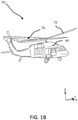
FIG. 1B illustrates a perspective view of a rotary aircraft, in accordance with various embodiments; -
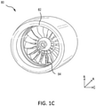
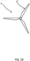
FIG. 1C illustrates a perspective view of an engine for an aircraft, in accordance with various embodiments; - FIG. ID illustrates a front view of a propeller for an aircraft, in accordance with various embodiments;
-
FIG. 2A illustrates an ice protection system for a blade of an aircraft, in accordance with various embodiments; -
FIG. 2B illustrates various cross-sections of the blade fromFIG. 2A , in accordance with various embodiments; -
FIG. 3 illustrates a heating element for use in an ice protection system, in accordance with various embodiments; -
FIG. 4 illustrates a metallized carbon nanotube (CNT) yarn for use in a heating element of an ice protection system, in accordance with various embodiments; -
FIG. 5 illustrates a heating element for use in an ice protection system, in accordance with various embodiments; -
FIG. 6 illustrates a heating element for use in an ice protection system, in accordance with various embodiments; -
FIG. 7 illustrates a heating element for use in an ice protection system, in accordance with various embodiments; -
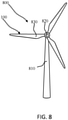
FIG. 8 illustrates a wind turbine including an ice protection system, in accordance with various embodiments. - Elements and steps in the figures are illustrated for simplicity and clarity and have not necessarily been rendered according to any particular sequence. For example, steps that may be performed concurrently or in different order are illustrated in the figures to help to improve understanding of embodiments of the present disclosure.
- The detailed description of exemplary embodiments herein makes reference to the accompanying drawings, which show exemplary embodiments by way of illustration. While these exemplary embodiments are described in sufficient detail to enable those skilled in the art to practice the disclosures, it should be understood that other embodiments may be realized and that logical changes and adaptations in design and construction may be made in accordance with this disclosure and the teachings herein. Thus, the detailed description herein is presented for purposes of illustration only and not of limitation.
- The scope of the disclosure is defined by the appended claims. For example, the steps recited in any of the method or process descriptions may be executed in any order and are not necessarily limited to the order presented. Furthermore, any reference to singular includes plural embodiments, and any reference to more than one component or step may include a singular embodiment or step. Also, any reference to tacked, attached, fixed, coupled, connected or the like may include permanent, removable, temporary, partial, full and/or any other possible attachment option. Additionally, any reference to without contact (or similar phrases) may also include reduced contact or minimal contact.
- In various embodiments, a heating element for use in ice protection systems are disclosed herein. The heating element may comprise a carbon nanotube (CNT) element and a metallic element. In various embodiments, the CNT element may be metallized to form the heating element. In various embodiments, the CNT element may be woven through a wire mesh to form the heating element. In various embodiments, the heating element may be lighter than typical metallic heating elements and contain higher conductivity relative to typical CNT heating elements.
- With reference to
FIG. 1A , anaircraft 10 is provided with aleft side wing 12 and aright side wing 14 designed to provide lift to the aircraft and enable it to fly. Theaircraft 10 may also be provided with any of a left side horizontal stabilizer, right side horizontal stabilizer, vertical stabilizer(s), and/or canards. Eachwing leading edge fuselage 20 to awing tip edge wing edges Aircraft leading edges edge edges edge wing leading edges aircraft 20, thewings wings - Referring now to
FIG. 1B , anaircraft 50, in accordance with various embodiments, is illustrated. Theaircraft 50 includes anairframe 60 mechanically coupled to amain rotor 70.Main rotor 70 may include a plurality of rotary blades. The plurality of rotor blades may include arotary blade 72. During operation of theaircraft 50, themain rotor 70 may be exposed to cold temperatures (e.g., below 0 °C) and/or benefit from an ice protection system. - Referring now to
FIG. 1C , a fixed-wing aircraft 10 or rotary-wing aircraft 50 can have one ormore engines 80. The engine(s) may have an air inlet with a plurality ofblades 82, each blade having a leading edge. If the engine is a gas turbine engine, it may have a plurality ofinlet guide vanes 84 with leading edges. During operation of theaircraft 10 oraircraft 80, the engine inlets may be exposed to cold temperatures (e.g., below 0 °C) and/or benefit from an ice protection system. - Referring now to
FIG 1D , a fixed-wing aircraft 10 orrotary wing aircraft 50 can have one ormore propellers 90 with leadingedges 92. During operation of theaircraft 10 oraircraft 50, thepropellers 90 may be exposed to cold temperatures (e.g., below 0 °C) and/or benefit from an ice protection system. In various embodiments,propellers 90 include blades, as disclosed herein. - Referring now to
FIG. 2A , anice protection system 100 for a blade of an aircraft (e.g.,aircraft 10 fromFIG. 1A and/oraircraft 50 fromFIG. 1B ) is illustrated, in accordance with various embodiments. Theice protection system 100 may include ablade 110 extending from aninboard end 112 to an outboard end 114 (e.g., a tip, or the like). Theblade 110 includes aleading edge 116 and a trailingedge 118. The ice protection system may further comprise a first heating element 121 (e.g., heater A) and a second heating element 131 (e.g., heater B). Thefirst heating element 121 may be disposed proximateleading edge 116 internal toblade 110 proximate theinboard end 112. Thesecond heating element 131 may be disposed internal toblade 110 and adjacent to thefirst heating element 121 distal toinboard end 112. - In various embodiments,
ice protection system 100 may further comprise a third heating element 141 (e.g., heater C). Thethird heating element 141 may be disposed proximateoutboard end 114 and/or distal toinboard end 112. In various embodiments, thesecond heating element 131 may be disposed betweenfirst heating element 121 andthird heating element 141. Thefirst heating element 121, thesecond heating element 131, and thethird heating element 141 may be configured for spanwise shedding of ice disposed on leadingedge 116 ofblade 110.First heating element 121,second heating element 131, andthird heating element 141 may be configured to heat leadingedge 116 independent of each other. In various embodiments,first heating element 121 andsecond heating element 131 may be active whilethird heating element 141 is inactive. In various embodiments, any number of heating elements may be active or inactive at a given time based on energy available to theice protection system 100 or the like. - Although described herein as including distinct heating elements disposed spanwise along the
leading edge 116 ofblade 110, the disclosure is not limited in this regard. For example, anice protection system 100 may include a single heating element or sequential heating elements, the heating element(s) may travel along the span of the airfoil, along the chord or wrap of the airfoil, in zig-zag pattern, in a serpentine pattern, or any other desirable pattern. - In various embodiments, each heating element (e.g.,
first heating element 121,second heating element 131, and/or third heating element 141) may be any electrothermal heater as described further herein. - Referring now to
FIG. 2B , cross sections of leadingedge 116 at each heater assembly location fromFIG. 2A is illustrated, in accordance with various embodiments. Referring to Section A-A of afirst portion 120 ofblade 110 may comprisefirst heating element 121, afirst laminate layer 122, asecond laminate layer 123, athird laminate layer 124, a second heater feedconductive element 126, and a second heater returnconductive element 127. Thefirst heating element 121 may be disposed between thefirst laminate layer 122 and thesecond laminate layer 123. The second heater feedconductive element 126 and the second heater returnconductive element 127 may be disposed between thesecond laminate layer 123 and thethird laminate layer 124. As illustrated, thefirst heating element 121 is separated from theexterior surface 119 by onelaminate layer 122. However, those skilled in the art will recognize that thefirst heating element 121 may be separated from theexterior surface 119 by any suitable number of laminate layers 122. Similarly, second heater feedconductive element 126 and second heater returnconductive element 127 may be disposed between any suitable number of laminate layers. In various embodiments, with combined reference toFIGs. 2A and 2B , second heater feedconductive element 126 and second heater returnconductive element 127 may extend frominboard end 112 to a connection point ofsecond heating element 131. - In various embodiments,
first portion 120 ofblade 110 may further comprise afourth laminate layer 125, a third heater feedconductive element 128, and a third heater return conductive element 129. The third heater feedconductive element 128 and the third heater return conductive element 129 may be disposed between thethird laminate layer 124 and thefourth laminate layer 125. - Referring to Section B-B of a
second portion 130 ofblade 110 may comprisesecond heating element 131,first laminate layer 122 andsecond laminate layer 123. Thesecond heating element 131 may be disposed between thefirst laminate layer 122 and thesecond laminate layer 123. - In various embodiments, the second heater feed
conductive element 126 and the second heater returnconductive element 127 may be discrete elements from thesecond heating element 131. In various embodiments, thesecond heating element 131 may be coupled to the second heater feedconductive element 126 and the second heater returnconductive element 127 by any method known in the art, such as soldering or the like. - In various embodiments,
second portion 130 ofblade 110 may further comprisethird laminate layer 124, third heater feedconductive element 128, and third heater return conductive element 129. The third heater feedconductive element 128 and the third heater return conductive element 129 may be disposed between thesecond laminate layer 123 and thethird laminate layer 124. In various embodiments, with combined reference toFIGs. 2A and 2B , third heater feedconductive element 128 and third heater return conductive element 129 may extend frominboard end 112 to a connection point ofthird heating element 141. - Referring to Section C-C of a
third portion 140 ofblade 110 may comprisethird heating element 141,first laminate layer 122 andsecond laminate layer 123. Thethird heating element 141 may be disposed between thefirst laminate layer 122 and thesecond laminate layer 123. - In various embodiments,
heating elements - In various embodiments, each heater feed
conductive element conductive element 127, 129 may be in electrical communication with apower source 150. Thepower source 150 may be configured to provide power to theheaters - Referring now to
FIG. 3 , a process of manufacturing aheating element 220 for use in an ice protection system (e.g.,ice protection system 100 fromFIGs. 2A and 2B ), is illustrated in accordance with various embodiments. In various embodiments,heating elements FIGs. 2A and 2B may be in accordance withheating element 220. In various embodiments, theheating element 220 comprises a carbon nanotube (CNT)fabric 210. In various embodiments, theCNT fabric 210 may be non-woven CNT fabric. In various embodiments, theCNT fabric 210 comprises a plurality ofcarbon nanotubes 212. In various embodiments, theCNT fabric 210 may be manufactured by synthesizing the plurality ofcarbon nanotubes 212 for an extended period of time within a reactor to form long carbon nanotubes that are entangled in an aerogel web, synthesizing the plurality ofcarbon nanotubes 212 on a substrate for alignment, or the like. - In various embodiments, the
CNT fabric 210 may undergo a metallization process to form theheating element 220. For example, a "metallization process" as described herein, may include electroplating, electroless plating, physical vapor deposition, chemical vapor deposition, and chemical deposition. In various embodiments, each carbon nanotube in the plurality ofcarbon nanotubes 212 of theheating element 220 include ametal coating 222 disposed on an outer surface of the respective carbon nanotube. In various embodiments, themetal coating 222 may infiltrate pores of theCNT fabric 210 to form theheating element 220. Themetal coating 222 may comprise copper, silver, nickel, aluminum, tin, gold, or a combination thereof. - In various embodiments, the
heating element 220 may comprise higher conductivity relative to typical heating elements in ice protection systems. For example, theheating element 220 may comprise an electric sheet resistivity between 0.01 and 0.5 ohms/square. In this regard, a large conductivity range may result in greater availability for a wide variety of ice protection applications, such as rotary blade applications, fixed wing applications, or the like. - Referring now to
FIG. 4 , a process of manufacturing ametallized CNT yarn 320 for use in a heating element of an ice protection system (e.g.,ice protection system 100 fromFIGs. 2A and 2B ), is illustrated in accordance with various embodiments. In various embodiments, the metallizedCNT yarn 320 comprises a carbon nanotube (CNT)yarn 310. In various embodiments, theCNT yarn 310 may undergo a metallization process to form the metallizedCNT yarn 320. The metallization process may be in accordance with the metallization process forheating element 220 fromFIG. 3 . The metallizedCNT yarn 320 may comprise theCNT yarn 310 and ametal coating 322 disposed on around an outer surface of the CNT yarn 310 (as shown in detail B). Themetal coating 222 may comprise copper, silver, nickel, aluminum, tin, gold, or a combination thereof. - In various embodiments, the metallization process may be performed prior to weaving the
CNT yarn 310 or after weaving theCNT yarn 310 into a heating element. For example, with reference now toFIGs. 5 and 6 , a process of manufacturing aheating element 420 for use in an ice protection system (e.g.,ice protection system 100 fromFIGs. 2A and 2B ), is illustrated in accordance with various embodiments. In various embodiments,heating elements FIGs. 2A and 2B may be in accordance withheating element 420. In various embodiments, theheating element 420 comprises a plurality of metallizedCNT yarn 320 fromFIG. 3 . In various embodiments, theCNT yarn 310 may be woven prior to metallization (e.g.,FIG. 6 ) or after metallization (e.g.,FIG. 5 ). In various embodiments, theheating element 420 comprises the plurality of metallizedCNT yarn 320 fromFIG. 4 in a woven pattern, or the like. - In various embodiments, the
heating element 420 may comprise higher conductivity relative to typical heating elements in ice protection systems. For example, theheating element 420 may comprise an electric sheet resistivity between 0.01 and 0.5 ohms/square. In this regard, a large conductivity range may result in greater availability for a wide variety of ice protection applications, such as rotary blade applications, fixed wing applications, or the like. - Referring now to
FIG. 7 , a process of manufacturing aheating element 720 for use in an ice protection system (e.g.,ice protection system 100 fromFIGs. 2A and 2B ), is illustrated in accordance with various embodiments. In various embodiments,heating elements FIGs. 2A and 2B may be in accordance withheating element 720. In various embodiments, theheating element 720 comprises aCNT yarn 310 and ametal mesh 722. Themetal mesh 722 may comprise copper, silver, nickel, aluminum, tin, gold, or a combination thereof. In various embodiments, theCNT yarn 310 may be woven through themetal mesh 722 via a textile weaving process and the process may be repeated until theheating element 720 is formed. In this regard, theheating element 720 may comprise a plurality of theCNT yarn 310 woven through ametal mesh 722 via a textile weaving process or the like. - In various embodiments, the
heating element 720 may comprise higher conductivity relative to typical heating elements in ice protection systems. For example, theheating element 720 may comprise an electric sheet resistivity between 0.01 and 0.5 ohms/square, or between 0.1 and 0.5 ohms/square. In this regard, a large conductivity range may result in greater availability for a wide variety of ice protection applications, such as rotary blade applications, fixed wing applications, or the like. - Referring now to
FIG. 8 , awind turbine 800, in accordance with various embodiments, is illustrated.Wind turbine 800 comprises atower 810, arotor 820, and ablade 830. In various embodiments,wind turbine 800 includes a plurality ofblade 830. In various embodiments,wind turbine 800 may includeice protection system 100. In various embodiments,wind turbine 800 may include an electrothermal heater that includes a heating element as disclosed herein (e.g.,heating element 220,heating element 420, and/or heating element 720). - Benefits, other advantages, and solutions to problems have been described herein with regard to specific embodiments. Furthermore, the connecting lines shown in the various figures contained herein are intended to represent exemplary functional relationships and/or physical couplings between the various elements. It should be noted that many alternative or additional functional relationships or physical connections may be present in a practical system. However, the benefits, advantages, solutions to problems, and any elements that may cause any benefit, advantage, or solution to occur or become more pronounced are not to be construed as critical, required, or essential features or elements of the disclosures. The scope of the disclosures is accordingly to be limited by nothing other than the appended claims, in which reference to an element in the singular is not intended to mean "one and only one" unless explicitly so stated, but rather "one or more." Moreover, where a phrase similar to "at least one of A, B, or C" is used in the claims, it is intended that the phrase be interpreted to mean that A alone may be present in an embodiment, B alone may be present in an embodiment, C alone may be present in an embodiment, or that any combination of the elements A, B and C may be present in a single embodiment; for example, A and B, A and C, B and C, or A and B and C.
- Systems, methods and apparatus are provided herein. In the detailed description herein, references to "various embodiments", "one embodiment", "an embodiment", "an example embodiment", etc., indicate that the embodiment described may include a particular feature, structure, or characteristic, but every embodiment may not necessarily include the particular feature, structure, or characteristic. Moreover, such phrases are not necessarily referring to the same embodiment. Further, when a particular feature, structure, or characteristic is described in connection with an embodiment, it is submitted that it is within the knowledge of one skilled in the art to affect such feature, structure, or characteristic in connection with other embodiments whether or not explicitly described. After reading the description, it will be apparent to one skilled in the relevant art(s) how to implement the disclosure in alternative embodiments.
Claims (11)
- An ice protection system comprising:an electrothermal heater configured to receive a current from a power source, the electrothermal heater comprising a first plurality of metallized carbon nanotube, CNT, elements (212) disposed in a first direction and a second plurality of metallized carbon nanotube, CNT, elements in a second direction.
- The ice protection system of claim 1, further comprising a blade (110), wherein the blade is a rotary blade for an aircraft, and wherein the electrothermal heater comprising an electric sheet resistivity between 0.01 and 0.5 ohms/square.
- The ice protection system of claim 1 or 2, wherein the first plurality of metallized CNT elements and the second plurality of metallized CNT elements form a metallized CNT fabric (210), or wherein the first plurality of metallized CNT elements and the second plurality of metallized CNT elements comprise a plurality of metallized CNT yarn (310), and optionally wherein the plurality of metallized CNT yarn form a woven pattern.
- The ice protection system of any preceding claim, wherein the electrothermal heater comprises a metallic mesh (722) and a CNT yarn (310), and optionally wherein the CNT yarn is woven through the metallic mesh.
- A blade assembly, comprising:an airfoil including a leading edge (116), a trailing edge (118), a pressure side and a suction side, the pressure side extending from the leading edge to the trailing edge, the suction side extending from the leading edge to the trailing edge; andan ice protection system (100) disposed on at least one of the leading edge, the pressure side, and the suction side, the ice protection system comprising an electrothermal heater coupled to the airfoil, the electrothermal heater comprising a carbon nanotube, CNT, fabric (210) or a CNT yarn (310) and a metal coating (222) at least partially infiltrating pores of the CNT fabric or yarn.
- The blade assembly of claim 5, wherein the ice protection system is disposed on the leading edge.
- The blade assembly of claim 5 or 6, wherein the CNT fabric or yarn undergoes a metallization process comprising at least one of electroplating, electroless plating, physical vapor deposition, chemical vapor deposition, and chemical deposition.
- The blade assembly of any of claims 5 to 7, wherein the electrothermal heater comprises an electric sheet resistivity between 0.01 and 0.5 ohms/square.
- The blade assembly of any of claims 5 to 8, wherein the airfoil is coupled to a main rotor (70).
- The blade assembly of any of claims 5 to 9, wherein the metal coating (222) comprises at least one of copper, silver, nickel, aluminum, tin, and gold.
- The blade assembly of any of claims 5 to 10, the electrothermal heater comprising a carbon nanotube, CNT, yarn (310) and further comprising a plurality of the CNT yarn, wherein the plurality of the CNT yarn forms a woven pattern.
Applications Claiming Priority (1)
| Application Number | Priority Date | Filing Date | Title |
|---|---|---|---|
| US16/933,833 US12356510B2 (en) | 2020-07-20 | 2020-07-20 | Metallized carbon nanotube elements for electrothermal ice protection |
Publications (2)
| Publication Number | Publication Date |
|---|---|
| EP3944723A1 true EP3944723A1 (en) | 2022-01-26 |
| EP3944723B1 EP3944723B1 (en) | 2025-11-19 |
Family
ID=76971764
Family Applications (1)
| Application Number | Title | Priority Date | Filing Date |
|---|---|---|---|
| EP21186458.2A Active EP3944723B1 (en) | 2020-07-20 | 2021-07-19 | Metallized carbon nanotube elements for electrothermal ice protection |
Country Status (2)
| Country | Link |
|---|---|
| US (1) | US12356510B2 (en) |
| EP (1) | EP3944723B1 (en) |
Citations (5)
| Publication number | Priority date | Publication date | Assignee | Title |
|---|---|---|---|---|
| US20130028744A1 (en) * | 2010-01-14 | 2013-01-31 | Pontus Nordin | Aerodynamic surface with improved properties |
| US20130043342A1 (en) * | 2010-01-14 | 2013-02-21 | Saab Ab | Multifunctional de-icing/anti-icing system |
| US20160366724A1 (en) * | 2010-01-26 | 2016-12-15 | Metis Design Corporation | Multifunctional cnt-engineered structures |
| EP3342702A1 (en) * | 2016-12-29 | 2018-07-04 | Goodrich Corporation | Erosion strip integrated with carbon allotrope-based deicing/ anti-icing elements |
| US20190357312A1 (en) * | 2018-05-16 | 2019-11-21 | Airbus Operations Gmbh | Structural component for an aircraft |
Family Cites Families (16)
| Publication number | Priority date | Publication date | Assignee | Title |
|---|---|---|---|---|
| US8080487B2 (en) * | 2004-09-20 | 2011-12-20 | Lockheed Martin Corporation | Ballistic fabrics with improved antiballistic properties |
| US20080166563A1 (en) | 2007-01-04 | 2008-07-10 | Goodrich Corporation | Electrothermal heater made from thermally conducting electrically insulating polymer material |
| AU2009244152A1 (en) | 2008-05-07 | 2009-11-12 | Nanocomp Technologies, Inc. | Nanostructure-based heating devices and method of use |
| SE1100140A1 (en) | 2011-03-01 | 2012-09-02 | Joachim Karthaeuser | Methods for producing metallized carbon nanoparticles |
| CA2873679A1 (en) | 2012-05-16 | 2013-11-21 | Jka Kemi Ab | Deicing of a surface of structures in general such as wind turbine blades, aircraft wings using induction or radiation |
| US11542018B2 (en) | 2015-01-06 | 2023-01-03 | Battelle Memorial Institute | Uniform heat distribution in resistive heaters for anti-icing and de-icing |
| US20190185632A1 (en) * | 2016-08-04 | 2019-06-20 | General Nano Llc | Carbon nanotube film structure and method for making |
| US10464680B2 (en) | 2016-08-30 | 2019-11-05 | The Boeing Company | Electrically conductive materials for heating and deicing airfoils |
| US10470250B2 (en) * | 2016-12-08 | 2019-11-05 | Goodrich Corporation | Carbon allotrope heater material with resistivity ranges suited for aircraft ice protection |
| US10425993B2 (en) * | 2016-12-08 | 2019-09-24 | Goodrich Corporation | Carbon nanotube yarn heater |
| US10115492B2 (en) | 2017-02-24 | 2018-10-30 | Delphi Technologies, Inc. | Electrically conductive carbon nanotube wire having a metallic coating and methods of forming same |
| US10807326B2 (en) | 2017-05-26 | 2020-10-20 | Goodrich Corporation | Method of making complex carbon nanotube sheets |
| US10854351B1 (en) * | 2017-08-31 | 2020-12-01 | United States Of America As Represented By The Secretary Of The Air Force | Highly conductive strain resilient material and method for making the material |
| US10998112B2 (en) | 2018-05-01 | 2021-05-04 | Minnesota Wire, Inc. | Carbon nanotube based cabling |
| US11424048B2 (en) * | 2018-06-28 | 2022-08-23 | Carlisle Interconnect Technologies, Inc. | Coaxial cable utilizing plated carbon nanotube elements and method of manufacturing same |
| DE102018218826A1 (en) * | 2018-11-05 | 2020-05-07 | Robert Bosch Gmbh | Heat exchanger |
-
2020
- 2020-07-20 US US16/933,833 patent/US12356510B2/en active Active
-
2021
- 2021-07-19 EP EP21186458.2A patent/EP3944723B1/en active Active
Patent Citations (5)
| Publication number | Priority date | Publication date | Assignee | Title |
|---|---|---|---|---|
| US20130028744A1 (en) * | 2010-01-14 | 2013-01-31 | Pontus Nordin | Aerodynamic surface with improved properties |
| US20130043342A1 (en) * | 2010-01-14 | 2013-02-21 | Saab Ab | Multifunctional de-icing/anti-icing system |
| US20160366724A1 (en) * | 2010-01-26 | 2016-12-15 | Metis Design Corporation | Multifunctional cnt-engineered structures |
| EP3342702A1 (en) * | 2016-12-29 | 2018-07-04 | Goodrich Corporation | Erosion strip integrated with carbon allotrope-based deicing/ anti-icing elements |
| US20190357312A1 (en) * | 2018-05-16 | 2019-11-21 | Airbus Operations Gmbh | Structural component for an aircraft |
Also Published As
| Publication number | Publication date |
|---|---|
| EP3944723B1 (en) | 2025-11-19 |
| US12356510B2 (en) | 2025-07-08 |
| US20220022286A1 (en) | 2022-01-20 |
Similar Documents
| Publication | Publication Date | Title |
|---|---|---|
| CA2746418C (en) | Anti-icing system and method for preventing ice accumulation | |
| US20180086470A1 (en) | Heating design for rotorcraft blade de-icing and anti-icing | |
| EP2715128B1 (en) | Wind turbine blade and related method of manufacture | |
| EP4069968B1 (en) | Equipotential bonding of wind turbine rotor blade | |
| US9771158B2 (en) | Ice protection of aerodynamic surfaces | |
| JP5933919B2 (en) | Turbomachine nacelle, anti-icing system and method thereof | |
| KR20080033155A (en) | Deformable conductive / resistive hybrid hybrid heaters for thermal ice machines | |
| EP3450320B1 (en) | Tailored rotor-blade ice-protection system | |
| EP3835210A1 (en) | Ice protection system for rotary blades | |
| EP2868575B1 (en) | Rotor blade with electrical interconnects | |
| CN110723294A (en) | Aircraft anti-icing system and method of making same | |
| EP2795118B1 (en) | A wind turbine blade | |
| EP3407678A1 (en) | Method of making complex carbon nanotube sheets | |
| EP3944723B1 (en) | Metallized carbon nanotube elements for electrothermal ice protection | |
| US20230112358A1 (en) | Robust power transmission | |
| US10696413B2 (en) | Blade heater mat insulation | |
| EP4379206A1 (en) | Improved electrical conductivity of wind turbine blade parts | |
| US11427336B2 (en) | High strain tolerant chord-wise ice protection layout | |
| KR20260064047A (en) | Layered assembly for preventing icing, aircraft wing, wind turbine blade, and aircraft including the same |
Legal Events
| Date | Code | Title | Description |
|---|---|---|---|
| PUAI | Public reference made under article 153(3) epc to a published international application that has entered the european phase |
Free format text: ORIGINAL CODE: 0009012 |
|
| STAA | Information on the status of an ep patent application or granted ep patent |
Free format text: STATUS: THE APPLICATION HAS BEEN PUBLISHED |
|
| AK | Designated contracting states |
Kind code of ref document: A1 Designated state(s): AL AT BE BG CH CY CZ DE DK EE ES FI FR GB GR HR HU IE IS IT LI LT LU LV MC MK MT NL NO PL PT RO RS SE SI SK SM TR |
|
| STAA | Information on the status of an ep patent application or granted ep patent |
Free format text: STATUS: REQUEST FOR EXAMINATION WAS MADE |
|
| 17P | Request for examination filed |
Effective date: 20220726 |
|
| RBV | Designated contracting states (corrected) |
Designated state(s): AL AT BE BG CH CY CZ DE DK EE ES FI FR GB GR HR HU IE IS IT LI LT LU LV MC MK MT NL NO PL PT RO RS SE SI SK SM TR |
|
| P01 | Opt-out of the competence of the unified patent court (upc) registered |
Effective date: 20230922 |
|
| GRAP | Despatch of communication of intention to grant a patent |
Free format text: ORIGINAL CODE: EPIDOSNIGR1 |
|
| STAA | Information on the status of an ep patent application or granted ep patent |
Free format text: STATUS: GRANT OF PATENT IS INTENDED |
|
| INTG | Intention to grant announced |
Effective date: 20250612 |
|
| GRAS | Grant fee paid |
Free format text: ORIGINAL CODE: EPIDOSNIGR3 |
|
| GRAA | (expected) grant |
Free format text: ORIGINAL CODE: 0009210 |
|
| STAA | Information on the status of an ep patent application or granted ep patent |
Free format text: STATUS: THE PATENT HAS BEEN GRANTED |
|
| RIN1 | Information on inventor provided before grant (corrected) |
Inventor name: HU, JIN Inventor name: SLANE, CASEY Inventor name: WAINA, DANIEL Inventor name: CHING, NATHANIEL Inventor name: HEIN, BRANDON |
|
| AK | Designated contracting states |
Kind code of ref document: B1 Designated state(s): AL AT BE BG CH CY CZ DE DK EE ES FI FR GB GR HR HU IE IS IT LI LT LU LV MC MK MT NL NO PL PT RO RS SE SI SK SM TR |
|
| REG | Reference to a national code |
Ref country code: CH Ref legal event code: F10 Free format text: ST27 STATUS EVENT CODE: U-0-0-F10-F00 (AS PROVIDED BY THE NATIONAL OFFICE) Effective date: 20251119 Ref country code: GB Ref legal event code: FG4D |
|
| REG | Reference to a national code |
Ref country code: DE Ref legal event code: R096 Ref document number: 602021042528 Country of ref document: DE |
|
| REG | Reference to a national code |
Ref country code: IE Ref legal event code: FG4D |
|
| REG | Reference to a national code |
Ref country code: NL Ref legal event code: MP Effective date: 20251119 |
|
| PG25 | Lapsed in a contracting state [announced via postgrant information from national office to epo] |
Ref country code: ES Free format text: LAPSE BECAUSE OF FAILURE TO SUBMIT A TRANSLATION OF THE DESCRIPTION OR TO PAY THE FEE WITHIN THE PRESCRIBED TIME-LIMIT Effective date: 20251119 |
|
| REG | Reference to a national code |
Ref country code: LT Ref legal event code: MG9D |
|
| PG25 | Lapsed in a contracting state [announced via postgrant information from national office to epo] |
Ref country code: NO Free format text: LAPSE BECAUSE OF FAILURE TO SUBMIT A TRANSLATION OF THE DESCRIPTION OR TO PAY THE FEE WITHIN THE PRESCRIBED TIME-LIMIT Effective date: 20260219 |
|
| PG25 | Lapsed in a contracting state [announced via postgrant information from national office to epo] |
Ref country code: AT Free format text: LAPSE BECAUSE OF FAILURE TO SUBMIT A TRANSLATION OF THE DESCRIPTION OR TO PAY THE FEE WITHIN THE PRESCRIBED TIME-LIMIT Effective date: 20251119 Ref country code: HR Free format text: LAPSE BECAUSE OF FAILURE TO SUBMIT A TRANSLATION OF THE DESCRIPTION OR TO PAY THE FEE WITHIN THE PRESCRIBED TIME-LIMIT Effective date: 20251119 Ref country code: FI Free format text: LAPSE BECAUSE OF FAILURE TO SUBMIT A TRANSLATION OF THE DESCRIPTION OR TO PAY THE FEE WITHIN THE PRESCRIBED TIME-LIMIT Effective date: 20251119 |
|
| REG | Reference to a national code |
Ref country code: AT Ref legal event code: MK05 Ref document number: 1860032 Country of ref document: AT Kind code of ref document: T Effective date: 20251119 |
|
| PG25 | Lapsed in a contracting state [announced via postgrant information from national office to epo] |
Ref country code: NL Free format text: LAPSE BECAUSE OF FAILURE TO SUBMIT A TRANSLATION OF THE DESCRIPTION OR TO PAY THE FEE WITHIN THE PRESCRIBED TIME-LIMIT Effective date: 20251119 |
|
| PG25 | Lapsed in a contracting state [announced via postgrant information from national office to epo] |
Ref country code: RS Free format text: LAPSE BECAUSE OF FAILURE TO SUBMIT A TRANSLATION OF THE DESCRIPTION OR TO PAY THE FEE WITHIN THE PRESCRIBED TIME-LIMIT Effective date: 20260219 |
|
| PG25 | Lapsed in a contracting state [announced via postgrant information from national office to epo] |
Ref country code: IS Free format text: LAPSE BECAUSE OF FAILURE TO SUBMIT A TRANSLATION OF THE DESCRIPTION OR TO PAY THE FEE WITHIN THE PRESCRIBED TIME-LIMIT Effective date: 20260319 |
|
| PG25 | Lapsed in a contracting state [announced via postgrant information from national office to epo] |
Ref country code: PT Free format text: LAPSE BECAUSE OF FAILURE TO SUBMIT A TRANSLATION OF THE DESCRIPTION OR TO PAY THE FEE WITHIN THE PRESCRIBED TIME-LIMIT Effective date: 20260319 |
|
| PG25 | Lapsed in a contracting state [announced via postgrant information from national office to epo] |
Ref country code: PL Free format text: LAPSE BECAUSE OF FAILURE TO SUBMIT A TRANSLATION OF THE DESCRIPTION OR TO PAY THE FEE WITHIN THE PRESCRIBED TIME-LIMIT Effective date: 20251119 |
|
| PG25 | Lapsed in a contracting state [announced via postgrant information from national office to epo] |
Ref country code: LV Free format text: LAPSE BECAUSE OF FAILURE TO SUBMIT A TRANSLATION OF THE DESCRIPTION OR TO PAY THE FEE WITHIN THE PRESCRIBED TIME-LIMIT Effective date: 20251119 |
|
| PG25 | Lapsed in a contracting state [announced via postgrant information from national office to epo] |
Ref country code: BG Free format text: LAPSE BECAUSE OF FAILURE TO SUBMIT A TRANSLATION OF THE DESCRIPTION OR TO PAY THE FEE WITHIN THE PRESCRIBED TIME-LIMIT Effective date: 20251119 |